EP3079621B1 - Catheter and handle assembly and systems - Google Patents
Catheter and handle assembly and systems Download PDFInfo
- Publication number
- EP3079621B1 EP3079621B1 EP14868857.5A EP14868857A EP3079621B1 EP 3079621 B1 EP3079621 B1 EP 3079621B1 EP 14868857 A EP14868857 A EP 14868857A EP 3079621 B1 EP3079621 B1 EP 3079621B1
- Authority
- EP
- European Patent Office
- Prior art keywords
- assembly
- handle
- ablation
- catheter
- delivery device
- Prior art date
- Legal status (The legal status is an assumption and is not a legal conclusion. Google has not performed a legal analysis and makes no representation as to the accuracy of the status listed.)
- Active
Links
- 238000002679 ablation Methods 0.000 claims description 159
- 238000011282 treatment Methods 0.000 claims description 56
- 239000002826 coolant Substances 0.000 claims description 53
- 230000008878 coupling Effects 0.000 claims description 49
- 238000010168 coupling process Methods 0.000 claims description 49
- 238000005859 coupling reaction Methods 0.000 claims description 49
- 230000007246 mechanism Effects 0.000 claims description 19
- 239000012530 fluid Substances 0.000 claims description 17
- 230000003287 optical effect Effects 0.000 claims description 16
- 230000002685 pulmonary effect Effects 0.000 claims description 10
- 238000013519 translation Methods 0.000 claims description 7
- 238000012800 visualization Methods 0.000 claims description 6
- 210000003437 trachea Anatomy 0.000 claims 1
- 210000001519 tissue Anatomy 0.000 description 27
- 238000000034 method Methods 0.000 description 26
- 210000004072 lung Anatomy 0.000 description 16
- 208000019693 Lung disease Diseases 0.000 description 15
- 230000000712 assembly Effects 0.000 description 15
- 238000000429 assembly Methods 0.000 description 15
- 238000001816 cooling Methods 0.000 description 15
- 230000006378 damage Effects 0.000 description 10
- 230000003902 lesion Effects 0.000 description 9
- 230000000007 visual effect Effects 0.000 description 9
- 208000006673 asthma Diseases 0.000 description 8
- 210000000621 bronchi Anatomy 0.000 description 8
- 208000000059 Dyspnea Diseases 0.000 description 7
- 206010013975 Dyspnoeas Diseases 0.000 description 7
- 230000002638 denervation Effects 0.000 description 7
- 208000006545 Chronic Obstructive Pulmonary Disease Diseases 0.000 description 6
- 238000012790 confirmation Methods 0.000 description 6
- 238000003466 welding Methods 0.000 description 6
- 238000004026 adhesive bonding Methods 0.000 description 5
- 230000008602 contraction Effects 0.000 description 5
- 210000004907 gland Anatomy 0.000 description 5
- 230000000670 limiting effect Effects 0.000 description 5
- 230000036961 partial effect Effects 0.000 description 5
- 238000007789 sealing Methods 0.000 description 5
- 206010061218 Inflammation Diseases 0.000 description 4
- 210000005091 airway smooth muscle Anatomy 0.000 description 4
- 230000000694 effects Effects 0.000 description 4
- 239000000835 fiber Substances 0.000 description 4
- 230000006870 function Effects 0.000 description 4
- 230000004054 inflammatory process Effects 0.000 description 4
- 238000012544 monitoring process Methods 0.000 description 4
- 210000005036 nerve Anatomy 0.000 description 4
- 208000024891 symptom Diseases 0.000 description 4
- 238000002604 ultrasonography Methods 0.000 description 4
- 230000004075 alteration Effects 0.000 description 3
- 238000009954 braiding Methods 0.000 description 3
- 210000003169 central nervous system Anatomy 0.000 description 3
- 239000003795 chemical substances by application Substances 0.000 description 3
- 201000010099 disease Diseases 0.000 description 3
- 208000037265 diseases, disorders, signs and symptoms Diseases 0.000 description 3
- 229940088597 hormone Drugs 0.000 description 3
- 239000005556 hormone Substances 0.000 description 3
- 239000002085 irritant Substances 0.000 description 3
- 231100000021 irritant Toxicity 0.000 description 3
- 230000003843 mucus production Effects 0.000 description 3
- 210000000653 nervous system Anatomy 0.000 description 3
- 230000000241 respiratory effect Effects 0.000 description 3
- 230000004044 response Effects 0.000 description 3
- 239000000126 substance Substances 0.000 description 3
- 230000009885 systemic effect Effects 0.000 description 3
- 238000002560 therapeutic procedure Methods 0.000 description 3
- 208000000884 Airway Obstruction Diseases 0.000 description 2
- 206010006458 Bronchitis chronic Diseases 0.000 description 2
- 206010008469 Chest discomfort Diseases 0.000 description 2
- 206010011224 Cough Diseases 0.000 description 2
- 102000004127 Cytokines Human genes 0.000 description 2
- 108090000695 Cytokines Proteins 0.000 description 2
- 206010014561 Emphysema Diseases 0.000 description 2
- 206010020880 Hypertrophy Diseases 0.000 description 2
- 206010030113 Oedema Diseases 0.000 description 2
- 208000037656 Respiratory Sounds Diseases 0.000 description 2
- 206010047924 Wheezing Diseases 0.000 description 2
- 230000001154 acute effect Effects 0.000 description 2
- QVGXLLKOCUKJST-UHFFFAOYSA-N atomic oxygen Chemical group [O] QVGXLLKOCUKJST-UHFFFAOYSA-N 0.000 description 2
- 238000009530 blood pressure measurement Methods 0.000 description 2
- 206010006451 bronchitis Diseases 0.000 description 2
- 208000007451 chronic bronchitis Diseases 0.000 description 2
- 230000001684 chronic effect Effects 0.000 description 2
- 238000004891 communication Methods 0.000 description 2
- 230000001276 controlling effect Effects 0.000 description 2
- 230000001351 cycling effect Effects 0.000 description 2
- 230000010339 dilation Effects 0.000 description 2
- 229940079593 drug Drugs 0.000 description 2
- 239000003814 drug Substances 0.000 description 2
- 239000007789 gas Substances 0.000 description 2
- JYGXADMDTFJGBT-VWUMJDOOSA-N hydrocortisone Chemical compound O=C1CC[C@]2(C)[C@H]3[C@@H](O)C[C@](C)([C@@](CC4)(O)C(=O)CO)[C@@H]4[C@@H]3CCC2=C1 JYGXADMDTFJGBT-VWUMJDOOSA-N 0.000 description 2
- 230000002757 inflammatory effect Effects 0.000 description 2
- 239000007924 injection Substances 0.000 description 2
- 238000002347 injection Methods 0.000 description 2
- 230000003993 interaction Effects 0.000 description 2
- 239000003550 marker Substances 0.000 description 2
- 238000005259 measurement Methods 0.000 description 2
- 210000003097 mucus Anatomy 0.000 description 2
- 239000002581 neurotoxin Substances 0.000 description 2
- 231100000618 neurotoxin Toxicity 0.000 description 2
- 229910052760 oxygen Inorganic materials 0.000 description 2
- 239000001301 oxygen Substances 0.000 description 2
- 230000002829 reductive effect Effects 0.000 description 2
- 230000001105 regulatory effect Effects 0.000 description 2
- 208000013220 shortness of breath Diseases 0.000 description 2
- 239000000779 smoke Substances 0.000 description 2
- 230000029547 smooth muscle hypertrophy Effects 0.000 description 2
- 210000000329 smooth muscle myocyte Anatomy 0.000 description 2
- 230000003068 static effect Effects 0.000 description 2
- 239000013589 supplement Substances 0.000 description 2
- 238000011477 surgical intervention Methods 0.000 description 2
- ZFXYFBGIUFBOJW-UHFFFAOYSA-N theophylline Chemical compound O=C1N(C)C(=O)N(C)C2=C1NC=N2 ZFXYFBGIUFBOJW-UHFFFAOYSA-N 0.000 description 2
- 230000008719 thickening Effects 0.000 description 2
- UCTWMZQNUQWSLP-VIFPVBQESA-N (R)-adrenaline Chemical compound CNC[C@H](O)C1=CC=C(O)C(O)=C1 UCTWMZQNUQWSLP-VIFPVBQESA-N 0.000 description 1
- 229930182837 (R)-adrenaline Natural products 0.000 description 1
- 101710138657 Neurotoxin Proteins 0.000 description 1
- 241000208125 Nicotiana Species 0.000 description 1
- 235000002637 Nicotiana tabacum Nutrition 0.000 description 1
- 208000031481 Pathologic Constriction Diseases 0.000 description 1
- 208000027418 Wounds and injury Diseases 0.000 description 1
- 230000005856 abnormality Effects 0.000 description 1
- 238000009825 accumulation Methods 0.000 description 1
- 239000000654 additive Substances 0.000 description 1
- 230000000996 additive effect Effects 0.000 description 1
- 239000000853 adhesive Substances 0.000 description 1
- 230000001070 adhesive effect Effects 0.000 description 1
- 239000003570 air Substances 0.000 description 1
- 208000037883 airway inflammation Diseases 0.000 description 1
- 239000013566 allergen Substances 0.000 description 1
- 210000003484 anatomy Anatomy 0.000 description 1
- 239000003242 anti bacterial agent Substances 0.000 description 1
- 229940088710 antibiotic agent Drugs 0.000 description 1
- 210000004556 brain Anatomy 0.000 description 1
- 229940124630 bronchodilator Drugs 0.000 description 1
- 239000000168 bronchodilator agent Substances 0.000 description 1
- 229940082638 cardiac stimulant phosphodiesterase inhibitors Drugs 0.000 description 1
- 230000006835 compression Effects 0.000 description 1
- 238000007906 compression Methods 0.000 description 1
- 230000003247 decreasing effect Effects 0.000 description 1
- 230000001419 dependent effect Effects 0.000 description 1
- 238000013461 design Methods 0.000 description 1
- 238000010586 diagram Methods 0.000 description 1
- 238000012377 drug delivery Methods 0.000 description 1
- 230000004064 dysfunction Effects 0.000 description 1
- 229960005139 epinephrine Drugs 0.000 description 1
- 210000003238 esophagus Anatomy 0.000 description 1
- 238000002594 fluoroscopy Methods 0.000 description 1
- 238000010438 heat treatment Methods 0.000 description 1
- 229960000890 hydrocortisone Drugs 0.000 description 1
- 230000001771 impaired effect Effects 0.000 description 1
- 238000007373 indentation Methods 0.000 description 1
- 210000004969 inflammatory cell Anatomy 0.000 description 1
- 208000014674 injury Diseases 0.000 description 1
- 238000003780 insertion Methods 0.000 description 1
- 230000037431 insertion Effects 0.000 description 1
- 238000005304 joining Methods 0.000 description 1
- 239000007788 liquid Substances 0.000 description 1
- 230000004199 lung function Effects 0.000 description 1
- 238000002483 medication Methods 0.000 description 1
- 230000000420 mucociliary effect Effects 0.000 description 1
- 210000000944 nerve tissue Anatomy 0.000 description 1
- 210000002569 neuron Anatomy 0.000 description 1
- 230000007935 neutral effect Effects 0.000 description 1
- 239000013307 optical fiber Substances 0.000 description 1
- 238000002640 oxygen therapy Methods 0.000 description 1
- RVTZCBVAJQQJTK-UHFFFAOYSA-N oxygen(2-);zirconium(4+) Chemical compound [O-2].[O-2].[Zr+4] RVTZCBVAJQQJTK-UHFFFAOYSA-N 0.000 description 1
- 230000001575 pathological effect Effects 0.000 description 1
- 230000002572 peristaltic effect Effects 0.000 description 1
- 238000011458 pharmacological treatment Methods 0.000 description 1
- 239000002571 phosphodiesterase inhibitor Substances 0.000 description 1
- 229920001296 polysiloxane Polymers 0.000 description 1
- 238000002360 preparation method Methods 0.000 description 1
- 238000007639 printing Methods 0.000 description 1
- 238000004886 process control Methods 0.000 description 1
- 230000009325 pulmonary function Effects 0.000 description 1
- 238000007674 radiofrequency ablation Methods 0.000 description 1
- 238000002601 radiography Methods 0.000 description 1
- 238000011084 recovery Methods 0.000 description 1
- 230000000306 recurrent effect Effects 0.000 description 1
- 230000009467 reduction Effects 0.000 description 1
- 230000011514 reflex Effects 0.000 description 1
- 230000029058 respiratory gaseous exchange Effects 0.000 description 1
- 210000002345 respiratory system Anatomy 0.000 description 1
- 230000000284 resting effect Effects 0.000 description 1
- 230000000717 retained effect Effects 0.000 description 1
- 230000002441 reversible effect Effects 0.000 description 1
- 239000003229 sclerosing agent Substances 0.000 description 1
- 238000012216 screening Methods 0.000 description 1
- 238000004513 sizing Methods 0.000 description 1
- 210000002460 smooth muscle Anatomy 0.000 description 1
- 238000005476 soldering Methods 0.000 description 1
- 230000036262 stenosis Effects 0.000 description 1
- 208000037804 stenosis Diseases 0.000 description 1
- 150000003431 steroids Chemical class 0.000 description 1
- 230000000638 stimulation Effects 0.000 description 1
- 229960000278 theophylline Drugs 0.000 description 1
- 230000000451 tissue damage Effects 0.000 description 1
- 231100000827 tissue damage Toxicity 0.000 description 1
- 238000012549 training Methods 0.000 description 1
- 210000001186 vagus nerve Anatomy 0.000 description 1
- 230000001755 vocal effect Effects 0.000 description 1
Images


Classifications
-
- A—HUMAN NECESSITIES
- A61—MEDICAL OR VETERINARY SCIENCE; HYGIENE
- A61B—DIAGNOSIS; SURGERY; IDENTIFICATION
- A61B18/00—Surgical instruments, devices or methods for transferring non-mechanical forms of energy to or from the body
- A61B18/04—Surgical instruments, devices or methods for transferring non-mechanical forms of energy to or from the body by heating
- A61B18/12—Surgical instruments, devices or methods for transferring non-mechanical forms of energy to or from the body by heating by passing a current through the tissue to be heated, e.g. high-frequency current
- A61B18/14—Probes or electrodes therefor
- A61B18/1492—Probes or electrodes therefor having a flexible, catheter-like structure, e.g. for heart ablation
-
- A—HUMAN NECESSITIES
- A61—MEDICAL OR VETERINARY SCIENCE; HYGIENE
- A61B—DIAGNOSIS; SURGERY; IDENTIFICATION
- A61B1/00—Instruments for performing medical examinations of the interior of cavities or tubes of the body by visual or photographical inspection, e.g. endoscopes; Illuminating arrangements therefor
- A61B1/00002—Operational features of endoscopes
- A61B1/00025—Operational features of endoscopes characterised by power management
- A61B1/00027—Operational features of endoscopes characterised by power management characterised by power supply
- A61B1/00032—Operational features of endoscopes characterised by power management characterised by power supply internally powered
-
- A—HUMAN NECESSITIES
- A61—MEDICAL OR VETERINARY SCIENCE; HYGIENE
- A61B—DIAGNOSIS; SURGERY; IDENTIFICATION
- A61B1/00—Instruments for performing medical examinations of the interior of cavities or tubes of the body by visual or photographical inspection, e.g. endoscopes; Illuminating arrangements therefor
- A61B1/00064—Constructional details of the endoscope body
- A61B1/0011—Manufacturing of endoscope parts
-
- A—HUMAN NECESSITIES
- A61—MEDICAL OR VETERINARY SCIENCE; HYGIENE
- A61B—DIAGNOSIS; SURGERY; IDENTIFICATION
- A61B1/00—Instruments for performing medical examinations of the interior of cavities or tubes of the body by visual or photographical inspection, e.g. endoscopes; Illuminating arrangements therefor
- A61B1/00112—Connection or coupling means
- A61B1/00114—Electrical cables in or with an endoscope
-
- A—HUMAN NECESSITIES
- A61—MEDICAL OR VETERINARY SCIENCE; HYGIENE
- A61B—DIAGNOSIS; SURGERY; IDENTIFICATION
- A61B1/00—Instruments for performing medical examinations of the interior of cavities or tubes of the body by visual or photographical inspection, e.g. endoscopes; Illuminating arrangements therefor
- A61B1/00112—Connection or coupling means
- A61B1/00121—Connectors, fasteners and adapters, e.g. on the endoscope handle
- A61B1/00128—Connectors, fasteners and adapters, e.g. on the endoscope handle mechanical, e.g. for tubes or pipes
-
- A—HUMAN NECESSITIES
- A61—MEDICAL OR VETERINARY SCIENCE; HYGIENE
- A61B—DIAGNOSIS; SURGERY; IDENTIFICATION
- A61B1/00—Instruments for performing medical examinations of the interior of cavities or tubes of the body by visual or photographical inspection, e.g. endoscopes; Illuminating arrangements therefor
- A61B1/00131—Accessories for endoscopes
- A61B1/00133—Drive units for endoscopic tools inserted through or with the endoscope
-
- A—HUMAN NECESSITIES
- A61—MEDICAL OR VETERINARY SCIENCE; HYGIENE
- A61B—DIAGNOSIS; SURGERY; IDENTIFICATION
- A61B1/00—Instruments for performing medical examinations of the interior of cavities or tubes of the body by visual or photographical inspection, e.g. endoscopes; Illuminating arrangements therefor
- A61B1/012—Instruments for performing medical examinations of the interior of cavities or tubes of the body by visual or photographical inspection, e.g. endoscopes; Illuminating arrangements therefor characterised by internal passages or accessories therefor
- A61B1/018—Instruments for performing medical examinations of the interior of cavities or tubes of the body by visual or photographical inspection, e.g. endoscopes; Illuminating arrangements therefor characterised by internal passages or accessories therefor for receiving instruments
-
- A—HUMAN NECESSITIES
- A61—MEDICAL OR VETERINARY SCIENCE; HYGIENE
- A61B—DIAGNOSIS; SURGERY; IDENTIFICATION
- A61B1/00—Instruments for performing medical examinations of the interior of cavities or tubes of the body by visual or photographical inspection, e.g. endoscopes; Illuminating arrangements therefor
- A61B1/267—Instruments for performing medical examinations of the interior of cavities or tubes of the body by visual or photographical inspection, e.g. endoscopes; Illuminating arrangements therefor for the respiratory tract, e.g. laryngoscopes, bronchoscopes
- A61B1/2676—Bronchoscopes
-
- A—HUMAN NECESSITIES
- A61—MEDICAL OR VETERINARY SCIENCE; HYGIENE
- A61B—DIAGNOSIS; SURGERY; IDENTIFICATION
- A61B17/00—Surgical instruments, devices or methods, e.g. tourniquets
- A61B17/24—Surgical instruments, devices or methods, e.g. tourniquets for use in the oral cavity, larynx, bronchial passages or nose; Tongue scrapers
-
- A—HUMAN NECESSITIES
- A61—MEDICAL OR VETERINARY SCIENCE; HYGIENE
- A61B—DIAGNOSIS; SURGERY; IDENTIFICATION
- A61B18/00—Surgical instruments, devices or methods for transferring non-mechanical forms of energy to or from the body
- A61B18/18—Surgical instruments, devices or methods for transferring non-mechanical forms of energy to or from the body by applying electromagnetic radiation, e.g. microwaves
- A61B18/1815—Surgical instruments, devices or methods for transferring non-mechanical forms of energy to or from the body by applying electromagnetic radiation, e.g. microwaves using microwaves
-
- A—HUMAN NECESSITIES
- A61—MEDICAL OR VETERINARY SCIENCE; HYGIENE
- A61B—DIAGNOSIS; SURGERY; IDENTIFICATION
- A61B17/00—Surgical instruments, devices or methods, e.g. tourniquets
- A61B17/24—Surgical instruments, devices or methods, e.g. tourniquets for use in the oral cavity, larynx, bronchial passages or nose; Tongue scrapers
- A61B2017/242—Surgical instruments, devices or methods, e.g. tourniquets for use in the oral cavity, larynx, bronchial passages or nose; Tongue scrapers for bronchial passages
-
- A—HUMAN NECESSITIES
- A61—MEDICAL OR VETERINARY SCIENCE; HYGIENE
- A61B—DIAGNOSIS; SURGERY; IDENTIFICATION
- A61B18/00—Surgical instruments, devices or methods for transferring non-mechanical forms of energy to or from the body
- A61B2018/00005—Cooling or heating of the probe or tissue immediately surrounding the probe
- A61B2018/00011—Cooling or heating of the probe or tissue immediately surrounding the probe with fluids
- A61B2018/00023—Cooling or heating of the probe or tissue immediately surrounding the probe with fluids closed, i.e. without wound contact by the fluid
-
- A—HUMAN NECESSITIES
- A61—MEDICAL OR VETERINARY SCIENCE; HYGIENE
- A61B—DIAGNOSIS; SURGERY; IDENTIFICATION
- A61B18/00—Surgical instruments, devices or methods for transferring non-mechanical forms of energy to or from the body
- A61B2018/00053—Mechanical features of the instrument of device
- A61B2018/00214—Expandable means emitting energy, e.g. by elements carried thereon
- A61B2018/0022—Balloons
-
- A—HUMAN NECESSITIES
- A61—MEDICAL OR VETERINARY SCIENCE; HYGIENE
- A61B—DIAGNOSIS; SURGERY; IDENTIFICATION
- A61B18/00—Surgical instruments, devices or methods for transferring non-mechanical forms of energy to or from the body
- A61B2018/00053—Mechanical features of the instrument of device
- A61B2018/00214—Expandable means emitting energy, e.g. by elements carried thereon
- A61B2018/00267—Expandable means emitting energy, e.g. by elements carried thereon having a basket shaped structure
-
- A—HUMAN NECESSITIES
- A61—MEDICAL OR VETERINARY SCIENCE; HYGIENE
- A61B—DIAGNOSIS; SURGERY; IDENTIFICATION
- A61B18/00—Surgical instruments, devices or methods for transferring non-mechanical forms of energy to or from the body
- A61B2018/00315—Surgical instruments, devices or methods for transferring non-mechanical forms of energy to or from the body for treatment of particular body parts
- A61B2018/00434—Neural system
-
- A—HUMAN NECESSITIES
- A61—MEDICAL OR VETERINARY SCIENCE; HYGIENE
- A61B—DIAGNOSIS; SURGERY; IDENTIFICATION
- A61B18/00—Surgical instruments, devices or methods for transferring non-mechanical forms of energy to or from the body
- A61B2018/00315—Surgical instruments, devices or methods for transferring non-mechanical forms of energy to or from the body for treatment of particular body parts
- A61B2018/00541—Lung or bronchi
-
- A—HUMAN NECESSITIES
- A61—MEDICAL OR VETERINARY SCIENCE; HYGIENE
- A61B—DIAGNOSIS; SURGERY; IDENTIFICATION
- A61B18/00—Surgical instruments, devices or methods for transferring non-mechanical forms of energy to or from the body
- A61B2018/00571—Surgical instruments, devices or methods for transferring non-mechanical forms of energy to or from the body for achieving a particular surgical effect
- A61B2018/00577—Ablation
-
- A—HUMAN NECESSITIES
- A61—MEDICAL OR VETERINARY SCIENCE; HYGIENE
- A61B—DIAGNOSIS; SURGERY; IDENTIFICATION
- A61B18/00—Surgical instruments, devices or methods for transferring non-mechanical forms of energy to or from the body
- A61B2018/00636—Sensing and controlling the application of energy
- A61B2018/00773—Sensed parameters
- A61B2018/00791—Temperature
- A61B2018/00821—Temperature measured by a thermocouple
-
- A—HUMAN NECESSITIES
- A61—MEDICAL OR VETERINARY SCIENCE; HYGIENE
- A61B—DIAGNOSIS; SURGERY; IDENTIFICATION
- A61B18/00—Surgical instruments, devices or methods for transferring non-mechanical forms of energy to or from the body
- A61B2018/0091—Handpieces of the surgical instrument or device
-
- A—HUMAN NECESSITIES
- A61—MEDICAL OR VETERINARY SCIENCE; HYGIENE
- A61B—DIAGNOSIS; SURGERY; IDENTIFICATION
- A61B18/00—Surgical instruments, devices or methods for transferring non-mechanical forms of energy to or from the body
- A61B2018/00982—Surgical instruments, devices or methods for transferring non-mechanical forms of energy to or from the body combined with or comprising means for visual or photographic inspections inside the body, e.g. endoscopes
-
- A—HUMAN NECESSITIES
- A61—MEDICAL OR VETERINARY SCIENCE; HYGIENE
- A61B—DIAGNOSIS; SURGERY; IDENTIFICATION
- A61B18/00—Surgical instruments, devices or methods for transferring non-mechanical forms of energy to or from the body
- A61B2018/00988—Means for storing information, e.g. calibration constants, or for preventing excessive use, e.g. usage, service life counter
-
- A—HUMAN NECESSITIES
- A61—MEDICAL OR VETERINARY SCIENCE; HYGIENE
- A61B—DIAGNOSIS; SURGERY; IDENTIFICATION
- A61B90/00—Instruments, implements or accessories specially adapted for surgery or diagnosis and not covered by any of the groups A61B1/00 - A61B50/00, e.g. for luxation treatment or for protecting wound edges
- A61B90/06—Measuring instruments not otherwise provided for
- A61B2090/064—Measuring instruments not otherwise provided for for measuring force, pressure or mechanical tension
- A61B2090/065—Measuring instruments not otherwise provided for for measuring force, pressure or mechanical tension for measuring contact or contact pressure
-
- A—HUMAN NECESSITIES
- A61—MEDICAL OR VETERINARY SCIENCE; HYGIENE
- A61B—DIAGNOSIS; SURGERY; IDENTIFICATION
- A61B90/00—Instruments, implements or accessories specially adapted for surgery or diagnosis and not covered by any of the groups A61B1/00 - A61B50/00, e.g. for luxation treatment or for protecting wound edges
- A61B90/06—Measuring instruments not otherwise provided for
- A61B2090/067—Measuring instruments not otherwise provided for for measuring angles
-
- A—HUMAN NECESSITIES
- A61—MEDICAL OR VETERINARY SCIENCE; HYGIENE
- A61B—DIAGNOSIS; SURGERY; IDENTIFICATION
- A61B90/00—Instruments, implements or accessories specially adapted for surgery or diagnosis and not covered by any of the groups A61B1/00 - A61B50/00, e.g. for luxation treatment or for protecting wound edges
- A61B90/39—Markers, e.g. radio-opaque or breast lesions markers
- A61B2090/3966—Radiopaque markers visible in an X-ray image
Definitions
- the present invention relates generally to systems and apparatuses for treating tissue, and more particularly, the invention relates to a catheter and handle system including a catheter positioning handle assembly that facilitates both circumferential and axial positioning of a distal end of the catheter positioned in an airway, conduit, or vessel.
- Pulmonary diseases are some of the most common medical conditions, affecting tens of millions of people in the U.S. alone. Pulmonary diseases result from problems in the respiratory tract that interfere with proper respiration. Many of these diseases require medical attention or intervention in order to restore proper lung function and improve a patient's overall quality of life.
- Some of the more common pulmonary diseases include asthma and chronic obstructive pulmonary disease or COPD. Symptoms of pulmonary disease like COPD and asthma vary but often include a persistent cough, shortness of breath, wheezing, chest tightness, and breathlessness. Generally, these symptoms are exacerbated when performing somewhat strenuous activities, such as running, jogging, brisk walking, etc. However, these symptoms may be noticed when performing non-strenuous activities, if the disease is allowed to progress unchecked. Over time, especially if medical attention is not sought, a person's daily activities will be significantly impaired, thus reducing overall quality of life.
- pulmonary diseases whether acute or chronic, often involve pathologic conditions associated with airway inflammation.
- infiltrated inflammatory cells cause damage to bronchial or lung tissue, which eventually results in the respiratory dysfunction characteristic of pulmonary diseases, such as reduction in respiratory flow rate or oxygen exchange capacity.
- this inflammation can lead to blockage of the airway lumen, thickening of the airway wall, and alteration of structures within or around the airway wall.
- Airway obstruction can significantly decrease the amount of gas exchanged in the lungs resulting in breathlessness. Blockage of an airway lumen can be caused by excessive intraluminal mucus, edema fluid, or both.
- Thickening of the airway wall may be attributable to excessive contraction of the airway smooth muscle, airway smooth muscle hypertrophy, mucous glands hypertrophy, inflammation, edema, or combinations of these. Alteration of structures around the airway, such as destruction of the lung tissue itself, can lead to a loss of circumferential traction on the airway wall and subsequent narrowing of the airway.
- pulmonary diseases like COPD and asthma are the result of a complex interplay of local inflammatory cytokines, inhaled irritants (e.g., cold air, smoke, allergens, or other chemicals), systemic hormones (e.g., cortisol and epinephrine), local nervous system input (i.e., nerve cells contained completely within the airway wall that can produce local reflex stimulation of smooth muscle cells and mucous glands), and the central nervous system input (i.e., nervous system signals from the brain to smooth muscle cells and mucous glands carried through the vagus nerve).
- inhaled irritants e.g., cold air, smoke, allergens, or other chemicals
- systemic hormones e.g., cortisol and epinephrine
- local nervous system input i.e., nerve cells contained completely within the airway wall that can produce local reflex stimulation of smooth muscle cells and mucous glands
- the central nervous system input i.e., nervous system signals from the brain
- Asthma can further include acute episodes or attacks of additional airway narrowing via contraction of hyper-responsive airway smooth muscle that significantly increases airflow resistance. Asthma symptoms include recurrent episodes of breathlessness (e.g., shortness of breath or dyspnea), wheezing, chest tightness, and coughing. Additionally, COPD, often referred to as emphysema, is characterized by the alteration of lung tissue surrounding or adjacent to the airways in the lungs. Emphysema can involve destruction of lung tissue (e.g., alveolar sacs) that leads to reduced gas exchange and reduced circumferential traction applied to the airway wall by the surrounding lung tissue.
- lung tissue e.g., alveolar sacs
- chronic bronchitis another type of COPD, is characterized by contraction of the airway smooth muscle, smooth muscle hypertrophy, excessive mucus production, mucous gland hypertrophy, and inflammation of airway walls. Like asthma, these abnormalities are the result of a complex interplay of local inflammatory cytokines, inhaled irritants, systemic hormones, local nervous system, and the central nervous system. Unlike asthma where respiratory obstruction may be largely reversible, the airway obstruction in chronic bronchitis is primarily chronic and permanent.
- Treatment for pulmonary diseases includes reducing exposure to harmful agents, administering medications (e.g., bronchodilators, steroids, phosphodiesterase inhibitors, theophylline, antibiotics, etc.), administering lung therapy (e.g., oxygen therapy, pulmonary rehabilitation), and surgical intervention, such as bronchial thermoplasty.
- administering medications e.g., bronchodilators, steroids, phosphodiesterase inhibitors, theophylline, antibiotics, etc.
- lung therapy e.g., oxygen therapy, pulmonary rehabilitation
- surgical intervention can result in the destruction of smooth muscle tone and nerve function, such that the patient is unable to respond favorably to inhaled irritants, systemic hormones, and both local and central nervous system input.
- targeted lung denervation An alternative method for treating pulmonary disease is referred to as targeted lung denervation.
- This method utilizes ablation, such as RF ablation, via an ablation assembly to selectively treat target regions inside of the airway wall (e.g., anatomical features in the stromas) while protecting the superficial tissues, such as the surface of the airway wall.
- target regions inside of the airway wall e.g., anatomical features in the stromas
- the mucous glands can be damaged to reduce mucus production a sufficient amount to prevent the accumulation of mucus that causes increased air flow resistance while preserving enough mucus production to maintain effective mucociliary transport, if needed or desired.
- Nerve branches/fibers passing through the airway wall or other anatomical features in the airway wall can also be destroyed.
- an ablation assembly generally comprising one or more collapsible electrodes or energy emitters, coupled to an expandable member, such as a balloon, into the airway of a patient via a delivery device.
- the delivery device can be a guide tube, a delivery sheath, a bronchoscope, or an endoscope and can include one or more viewing devices, such as optical viewing devices (e.g., cameras), optical trains (e.g., a set of lens), optical fibers, CCD chips, and the like.
- Energy such as RF energy
- RF energy is supplied to the energy emitter to ablate the targeted tissue, causing a lesion to form, therefore temporarily or permanently damaging the targeted tissue, therefore affecting, e.g. attenuating nerve signals to or from, portions of the lungs associated with the targeted tissue.
- a coolant is supplied through the catheter and is directed to the one or more electrodes and into the expandable member or balloon. This allows for cooling of the superficial tissue in contact with the electrode, as well as the adjacent tissues.
- the size, shape, and depth of the lesions are determined by the flow rate and temperature of the coolant, and the energy supplied to the energy emitter(s).
- Devices, systems, and methods of such procedures can be found, for example, in one or more of U.S. Patent Nos.
- a circumferential lesion may be formed by ablating tissue while slowly rotating the ablation assembly or by positioning the ablation assembly in a series of rotational positions at each of which energy is delivered for a desired time period. The adjacent lesions then become contiguous and form a circumferential band all the way around the airway wall. Additionally or alternatively, the catheter may be repositioned axially to treat other locations within the airway distally or proximally of the first treatment site.
- a bronchoscope may be introduced into the target airway and the treatment catheter then delivered either alongside the bronchoscope or, more preferably, through the working channel of the bronchoscope.
- placement through the working channel can create challenges in manipulating the catheter due to the small size of the working channel, friction between the catheter and the walls of the working channel, and, in the case of flexible bronchoscopes, the curvature or tortuosity of the working channel.
- Disorientation of the electrode in the treatment site and/or unintended movement of the catheter relative to the bronchoscope during treatment may result in treatment inaccuracies, causing axial or circumferential misalignment of lesions, undesirable gaps between lesions, or excessive overlap between lesions.
- pulmonary treatment catheters such as targeted lung denervation catheters
- electrode orientation when positioned in a pulmonary airway through a delivery device such as the working channel of bronchoscope.
- EP2022431 discloses a catheter and handle assembly of the prior art.
- Embodiments of the invention are directed to a pulmonary treatment catheter and handle system including a catheter assembly, a handle assembly, and a scope coupling assembly for coupling the handle assembly and catheter assembly to a delivery device, such as a bronchoscope.
- a delivery device such as a bronchoscope.
- kit including the catheter assembly and handle assembly for coupling together and to a delivery device, such as a bronchoscope, via the scope coupling assembly, and instructions for methods of using such.
- the catheter assembly is further fluidly and electrically coupled to a system console, including a coolant supply and return reservoir, and an energy supply such as a RF generator, via the handle assembly.
- the catheter assembly, handle assembly, and scope coupling assembly cooperate together to facilitate both circumferential and axial positioning of a catheter electrode in a treatment site, such as an airway, conduit, or vessel for treatment of the tissue, while maintaining known rotational and axial orientation of portions of the catheter assembly, such as an ablation assembly including an energy emitter or electrode, within the treatment site.
- the system can further facilitate optical coupling of the ablation assembly of the catheter assembly with a viewing device, such as a fiber optic camera at a working end of a bronchoscope, while maintaining independent movement of the viewing device with respect to the ablation assembly to achieve maximum viewing flexibility of the treatment site and ablation assembly. This allows for full viewing access of the electrode of the ablation assembly within the treatment site regardless of its or orientation or positioning within the treatment site.
- the catheter assembly comprises a targeted lung denervation RF, microwave, or ultrasound catheter, and generally includes an elongate shaft, and an ablation assembly coupled to a distal portion of the shaft, the ablation assembly including an expandable member, such as a balloon or basket, and one or more electrodes or energy emitters coupled to the expandable member.
- the catheter assembly also includes a cooling circuit including a coolant inflow and outflow lumen within the elongate shaft, and a coolant inlet path and return path (e.g.
- cooling conduit(s)) to circulate coolant to the expandable member and to the energy emitter, one or more power wires for supplying power to the energy emitter, optional thermocouple(s) and associated wires for measuring and sensing temperature at locations proximal to the electrode, optional cooling circuit pressure sensors and associated wired for measuring and sensing pressure within the cooling circuit, and/or optional pressure relief valves.
- the handle assembly is coupled to a proximal portion of the shaft.
- the handle assembly can include a housing fixedly coupled to the proximal end of the shaft, and a spindle tube or handle frame coupled to the housing such that the spindle tube is rotatably and axially shiftable with respect to the housing and the catheter assembly.
- the handle assembly can further include an umbilical cable with strain relief for coupling the handle assembly, and ultimately the catheter assembly, to a system console including a heat exchanger, coolant pump, energy generator (such as an RF, microwave, or ultrasound generator), and a system controller.
- the umbilical cable can aid in coupling, for example, inlet and return fluid tubes (coolant) from the system console for fluidly coupling the catheter assembly to the heat exchanger and pump of the console, an electrical cable/connector to electrically connect the electrode of the catheter assembly to an energy source, thermocouple wires to monitor temperature of the surface tissue of the treatment site, the electrode, or both, and/or pressure sensors to monitor the high pressure coolant inlet flow and the low pressure return flow.
- inlet and return fluid tubes coolant
- the scope coupling assembly removably couples the handle assembly and catheter assembly to a working channel of a delivery device, such as a bronchoscope, in a unique or single orientation, such that the initial rotational and axial orientation of the catheter assembly with respect to the working end or tip of the bronchoscope is known.
- the coupling assembly is fixedly coupled to the spindle tube, such that the handle housing and catheter assembly are rotatably and axially shiftable with respect to the working channel.
- the handle assembly is configured to maneuver the distal portion of the catheter shaft having the ablation assembly thereon with respect to the delivery device and airway wall, in axial and circumferential directions during or in preparation for the administration of treatment for a pulmonary disease.
- the delivery device is a bronchoscope that comprises a working channel or port through which the elongate shaft and ablation assembly of the catheter can be inserted, and the handle assembly can be secured to the bronchoscope in a manner that functionally engages the handle assembly movements with the bronchoscope and the ablation assembly of the catheter assembly.
- the handle assembly can be fixed to the bronchoscope such that the shaft of the catheter assembly, and therefore the ablation assembly, rotates and axially translates with corresponding rotational and axial translation of the bronchoscope for coarse adjustment of the ablation assembly within the airway.
- the handle assembly may also include one or more steering or manipulation mechanisms that are functionally coupled with the shaft and/or ablation assembly to translate the shaft and/or ablation assembly rotationally and/or axially with respect to the scope for either coarse or fine circumferential and/or axial adjustment while other portions of the handle assembly remain engaged with and stationary relative to the bronchoscope.
- a length of the elongate shaft of the catheter assembly and the manipulation mechanism of the handle assembly are configured to allow for a travel length of the ablation assembly to be equal to or greater than a longitudinal length of the ablation assembly such that an axial stroke of the handle assembly (fully retracted to fully extended) allows the ablation assembly to shift between being fully extended out of the working end or tip (with or without a gap outside of the working end) of the bronchoscope to fully retracted within the working end of the bronchoscope (with or without a gap inside of the working end).
- a user can maneuver the bronchoscope, and the elongate shaft and ablation assembly thereon, into a position advantageous for conducting treatment for a pulmonary disease (e.g., a targeted lung denervation procedure).
- the handle assembly can comprise controls for independently adjusting the distal portion of the elongate shaft of the catheter and/or the ablation assembly from the bronchoscope.
- the handle assembly can comprise independent control mechanisms for axial translation of the catheter assembly and rotational movement of the catheter assembly with respect to the working channel of the bronchoscope.
- the handle is permanently or temporarily coupled to the catheter assembly, and the distal portion of the catheter shaft and ablation assembly are inserted into the working channel or port of a delivery device, such as a bronchoscope.
- the handle assembly is then coupled to the bronchoscope via the coupling assembly in a unique orientation.
- the distal portion of the delivery device can comprise a visualization device, a camera, and/or an aspiration lumen or vacuum.
- the distal end of the catheter shaft and ablation assembly can be positioned using the axial and circumferential controls of the handle assembly, such that a specific portion of airway tissue can be targeted for treatment (e.g., radio frequency energy emission from an electrode).
- the working end of bronchoscope can be maneuvered independently of the catheter shaft and ablation assembly.
- the handle assembly can be used to more accurately position an electrode of the ablation assembly based on visual cues from the camera of the delivery device, without moving the delivery device and camera.
- the distal end of the catheter assembly includes a longitudinal indicator band or stripe.
- the indicator band aligns with the center point of the camera of the bronchoscope.
- This band provides a visual confirmation of the ablation assembly orientation within the treatment site, and regardless of the rotational orientation of the bronchoscope within the treatment site, the location of the ablation assembly with respect to the working end of the bronchoscope is known. Furthermore, the band provides a visual confirmation of the axial location of the ablation assembly with respect to the working end of the bronchoscope to provide optimal optical coupling of the bronchoscope camera and the ablation assembly.
- the system allows for one-handed operation of both the catheter assembly and the bronchoscope when rotated and/or translated axially together for coarse adjustment, as well as for the independent rotationally and axial fine adjustment of the ablation assembly with respect to the bronchoscope.
- a catheter and handle system 100 can comprise an ablation catheter assembly 101 having an elongate shaft 102 and an ablation assembly 106 coupled to a first or distal end of shaft 102, a positioning handle assembly 104 coupled to a second or proximal end of shaft 102, and a scope coupling assembly 103 for coupling catheter assembly 101 and handle assembly 104 to a working channel of a delivery device, such as a bronchoscope.
- Catheter assembly 101 is further fluidly and electrically coupled to a system console (not shown), including a coolant supply and return reservoir, and an energy supply such as a RF generator, via handle assembly 104.
- Handle assembly 104 is configured to maneuver the distal portion or end of shaft 102 and therefore ablation assembly 106 in axial and circumferential directions during the administration of treatment.
- ablation assembly 106 can comprise one or more energy emitters 510, such as an electrode, and an expandable member 520, such as a balloon or basket.
- ablation assembly 106 can comprise a coolant fluid path or cooling circuit 600 to cool electrode 510 and a surface of expandable member 520 to protect surface tissue in contact with electrode 510 and adjacent to electrode 510. As depicted in Fig.
- cooling circuit 600 includes coolant supplied from a reservoir 601 of a system console, through an optional heat exchanger 603 of the system console, through handle 104, through an inflow lumen in shaft 102, through conduit 540 to which electrode 510 is coupled, through expandable member 520, through an outflow lumen in shaft 102, through handle 104, and back to the system console.
- a system console can be found in U.S. Patent Application Publication No. 2013/0289556 , entitled “Delivery Devices with Coolable Energy Emitting Assemblies" and U.S. Patent No. 8,489,192 entitled “System and Method for Bronchial Dilation.” Cycling of the fluid is accomplished, for example, by a peristaltic pump 605. In an alternative embodiment, the flow is reversed such that the coolant flows through the expandable member before the electrode.
- ablation assembly 106 can optionally comprise a throttle valve 530 for regulating the flow between conduit 540 and expandable member 520.
- Ablation assembly 106 can also optionally comprise a support wire 1214, such as a Nitonol wire, extends along at least a length of catheter shaft 102 and between an interior of a proximal end 520a and distal end 520b of expandable member 520 to provide added axial, torsional, and buckling support for expandable member 520 and catheter shaft 102.
- a support wire 1214 such as a Nitonol wire
- a first portion or end of 1214a of support wire 1214 is coupled to the distal end 102a of catheter shaft 102, while a second end 1214b is coupled to the distal end 520b of expandable member 520 at a junction between throttle value 530 and expandable member 520.
- handle assembly 104 can comprise an umbilical cable 120 coupled to an end of handle assembly 104 via strain relief 121 for fluidly and/or electrically coupling catheter assembly 101 to accompanying devices or accessories, such as a power source, energy source, fluid or coolant supply, heat exchanger, and controller, preferably combined in a system console.
- accompanying devices or accessories such as a power source, energy source, fluid or coolant supply, heat exchanger, and controller, preferably combined in a system console.
- Umbilical cable 120 can include, for example, connections for inlet and return fluid tubes or lumens 105 for fluidly coupling shaft 102 to a fluid or coolant supply, from the console which optionally includes a heat exchanger for cooling and/or heating input fluid, and one or more electrical cable/connector 107 to electrically connect the shaft and/or ablation assembly to a power source, thermocouples for temperature monitoring, and/or pressure sensors for coolant circuit pressures.
- handle assembly 104 can comprise an internal battery source for operating handle assembly 104 and any accompanying devices or accessories.
- catheter assembly 101 and handle assembly 104 are capable of coupling to a delivery device 200, such as, for example, a guide tube, a delivery sheath, a bronchoscope, or an endoscope.
- Delivery device 200 can include one or more viewing devices, such as optical viewing devices (e.g., cameras), optical trains (e.g., a set of lens), and the like.
- delivery device 200 comprises a flexible bronchoscope.
- Ablation assembly (not shown) and elongate shaft 102 are inserted into a working channel port 202 of device 200.
- Handle assembly 104 is then secured to device 200 via a scope coupling assembly 103.
- Scope coupling assembly 103 can be integral with or coupled to handle assembly 104, or can be its own stand-alone adapter coupling to both handle assembly 104 and port 202. Scope coupling assembly 103 securely fits to port 202, such as by frictional or abutting fit, locking lever, threaded engagement of corresponding threads, bayonet or snap fit, spring loaded fit, or any of a variety of mechanisms known to those skilled in the art. Scope coupling assembly 103 further can include a locking mechanism 208 such as a lever or slide lock to prevent unintended disengagement of handle assembly 104 from port 202. Once secured, scope coupling assembly 103 is fixed axially and rotationally with respect to device 200. If not previously assembled, handle assembly 104 is then secured to scope coupling assembly 103, as will be described in more detail below.
- handle assembly 104 generally comprises a handle housing or cover 1002 thereby defining an interior space of handle assembly 104 having a longitudinal axis A, and a handle frame, such as a spindle tube 1024.
- housing 1002 comprises a first handle housing 1002a and second handle housing 1002b coupled to first handle housing 1002a via one or more a mortise and tenon joints, corresponding male and female interlocking parts, screws, adhesive, welding, or any of a variety of mechanisms for joining the housings.
- the housing is monolithic, or alternatively, formed of more than two pieces.
- catheter shaft 102 includes a central coolant inlet lumen 102a for supplying fresh or recycled coolant from a coolant supply of the system console to the ablation assembly coupled to a distal end of catheter 102 (e.g. shown in Fig. 6 ).
- a coolant return lumen 102b surrounds coolant inlet lumen 102a such that the coolant return lumen 102b and coolant inlet lumen 102a are coaxial.
- other arrangements that are not coaxial such as side-by-side, can also be contemplated.
- an umbilical cable assembly 1006 of handle assembly 104 at a proximal end couples coolant inlet lumen 102a and coolant return lumen 102b of shaft 102 to a coolant supply source and return reservoir.
- umbilical cable assembly 1006 can couple any of a variety of tubes and/or electrical wires or cables to catheter tube 1004 and/or handle assembly 104 for fluidly and/or electrically coupling catheter shaft 102 and ultimately ablation assembly 106 to accompanying devices or accessories, such as a power source, energy source, fluid or coolant supply, heat exchanger, and controller, preferably combined in a system console.
- umbilical cable assembly 1006 comprises flexible umbilical cable 120 terminating in a rubber strain relief 121.
- catheter tube 1004 and the proximal end of shaft 102 are operably coupled to umbilical cable assembly 1006 via a manifold 1008.
- Manifold 1008 distributes or redirects the inflow, outflow, and/or electrical flows between shaft 102 and the system console (not shown).
- manifold 1008 comprises a first inlet port 1008a and a second inlet port 1008b.
- First inlet port 1008a and second inlet port 1008b are in fluid communication with each other via conduits 1009a and 1009b and gate 1111.
- a proximal end of coolant supply tube 1006a of umbilical cable assembly 1006 extends within and is bonded to an interior surface of first port 1008a of manifold 1008 by adhesive bonding, heat sealing, ultrasonic welding, or any of a variety of attachment mechanisms.
- a distal end (not shown) of coolant supply tube 1006a is coupled to a coolant supply, optional heat exchange, and pump of the system console.
- Inlet lumen 102a and outlet lumen 102b of shaft 102 extends within second port 1008b of manifold 1008, and outlet lumen 102b is bonded to an interior surface of port 1008b by adhesive bonding, heat sealing, ultrasonic welding, or any of a variety of attachment mechanisms.
- Inlet lumen 102a extends beyond outlet lumen 102b of shaft 102 through conduits 1009a and 1009b, and into coolant supply tube 1006a.
- a diameter of conduit 1009b is similar to a diameter of inlet lumen 102a, such that inlet lumen 102a can be bonded to an interior surface of conduit 1009b by adhesive bonding, heat sealing, ultrasonic welding, or any of a variety of attachment mechanisms.
- Manifold 1008 further comprises a third port 1008c.
- a proximal end of coolant return tube 1006b of umbilical cable assembly 1006 extends within port 1008c and is bonded to an interior surface of third port 1008c by adhesive bonding, heat sealing, ultrasonic welding, or any of a variety of attachment mechanisms.
- Third port 1008c is in fluid communication with second port 1008b, and therefore outlet lumen 102b secured thereto, via conduits 1009c and 1009a, separated by gate 1111.
- a distal end (not shown) of coolant return tube 1006b is coupled to a reservoir of the system console for recycle and/or disposal of coolant.
- coolant is supplied from the coolant supply of the system counsel through coolant supply tube 1006a of umbilical cable assembly 1006. Coolant then flows from coolant supply tube 1006a into inflow lumen 102a of catheter shaft 102. Coolant flows along the length of shaft 102 into ablation assembly 106, as described below. The coolant circulates through ablation assembly 106 and into outlet lumen 102b, along the length of shaft 102 into manifold conduit 1009a, reservoir, 1111, and conduit 1009c. Coolant flows out of manifold 1008 via coolant return tube 1006b and back to the system console for recycle and/or disposal.
- catheter tube 1004 is bonded to an exterior surface of second port 1008a of manifold 1008, thereby covering second port 1008a and the portion of shaft 102 extending within and along handle assembly 100.
- Catheter tube 1004 is secured to manifold 1008 by adhesive bonding, heat sealing, ultrasonic welding, or any of a variety of attachment mechanisms.
- manifold 1008 can further comprise a recessed seat 1113 formed in a surface thereof for receiving and securing one or more printed circuit boards thereto, such as by soldering or additive printing directly thereon, and one or more liquid pressure sensors and gauges, flow sensors and gauges, and/or thermocouples for detecting and optionally displaying pressures, coolant inlet and outlet flow rates, and/or temperatures at various locations in the catheter assembly 101 and/or ablation assembly 106. Leads from the pressure sensor, flow sensors, and/or thermocouples are then fed through an aperture 1115 formed in seat 1113 of manifold 1008 which fluidly couples seat 1113 with gate 1111. The leads extend through shaft 102 to ultimately reach ablation assembly 106. In an embodiment, and referring back to Fig. 8 , a first lead 1010a and a second lead 1010b are fed through outlet lumen 102b of shaft 102 to ablation assembly 106.
- Manifold 1008 is fixedly coupled to an interior of first and/or second handle cover 1002a,b such that manifold 1008 and therefore catheter tube 1004 are fixed axially and rotationally to covering 1002.
- Manifold 1008 can be fixed to handle cover 1002a and/or 1002b by insertion of a peg formed on the interior of housing 1002a or b into a corresponding sleeve 1117 formed on manifold 1008 as seen in Fig. 12 , for example.
- any of a variety of attachment mechanisms can be contemplated.
- Thermocouples can be placed anywhere within the catheter assembly 101 including at the energy emitter or electrode site of the ablation assembly 106, within the cooling member of the ablation assembly to measure the temperature of the coolant in the cooling member, and/or within the inflow and/or outflow lumens 102a, 102b in the elongate shaft 102 to measure the temperatures of the inflow and/or outflow coolant flows. Coolant temperature and/or coolant flow are then either manually or automatically regulated at the system console to ensure that the ablation site is sufficiently heated to cause permanent damage to target tissue, while ensuring that surface tissue in contact with the electrode and cooling member is sufficiently cooled to inhibit or prevent permanent damage to the surface tissue.
- Pressure and/or flow rate can be measured within the inflow and/or outflow lumens, and/or within the cooling member and/or ablation assembly to measure theoretical and/or direct pressure of the ablation assembly.
- Pressure within the inflow lumen can be high compared to pressure within the outflow lumen due to a throttle positioned within the ablation assembly.
- a pressure of the expandable member, e.g. balloon, of the ablation assembly is held at a pressure less than a predetermined pressure to guard against over-dilating or over-sizing the balloon within the airway, which can cause unwanted damage to the airway.
- a pressure sensor such as one positioned on the handle, will detect the buildup of pressure in the corresponding line and will automatically trigger the coolant pump to shut off so as not to rupture the expandable cooling member or over-dilate the balloon, and/or the energy source for the electrode to shut off so that the treatment site does not overheat.
- pressure relief valves may be incorporated within the system to alleviate a buildup of pressure at a predetermined or user-controlled pressure limit. Specific pressure measurement assemblies are described in more detail below.
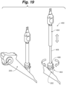
- a pressure sensor 1200 is positioned on or near the handle assembly 1202 and is configured to measure the pressure of the outlet lumen 1204 of catheter shaft 1203. This embodiment is based on a pressure measurement downstream (i.e. the outlet lumen 1204) of the ablation assembly 1206, thereby requiring a theoretical pressure offset to estimate the pressure in the expandable member 1208 of the ablation assembly 1206. In this embodiment, it is estimated that a pressure in the expandable member 1208 is greater than a pressure at gauge 1200 due to the resistance of flow in the catheter shaft 1203 relative to the expandable member 1208.
- a direct measurement of the pressure in the balloon or ablation assembly 1206 is desired so as to eliminate or reduce undetected obstructions or occlusions between pressure sensor 1200 and the expandable member 1208, which can cause possible over-inflation or rupturing of the expandable member 1208.
- a pressure sensor 1200 is positioned on or near the handle assembly 1202.
- a polymeric and/or metallic tube 1210 is positioned along outflow lumen 1204 of catheter shaft 1203.
- a first end 1210a of tube 1210 is operably coupled to the pressure sensor 1200 while a second end 1210b terminates within ablation assembly 1206.
- Tube 1210 acts as a static column to measure the pressure directly in ablation assembly 1206; i.e. the pressure through catheter shaft 1203 within tube 1210 is constant such that the pressure measured at pressure sensor 1200 is equal to the pressure in ablation assembly 1206.
- tube 1210 can be flexible or rigid.
- a support wire 1214 such as a Nitinol wire, extends between an interior of a proximal and distal end of expandable member 1208 to provide added axial, torsional, and buckling support for expandable member 1208. More particularly, a first end 1214a of support wire 1214 is coupled to the distal end 1203a of catheter shaft 1203, while a second end 1214b is coupled to the distal end of expandable member 1208 at a junction between throttle valve 1209 and expandable member 1208.
- tube 1210 can supplement support wire 1214.
- a pressure tube 1220 replaces the support wire of the previous embodiments.
- tube 1220 is coupled at first end 1220a to pressure sensor 1200 positioned on or near the handle assembly 1202.
- a distal portion 1222 of tube 1220 extends between a proximal and distal end of expandable member 1208. More specifically, a proximal end 1222a of distal portion 1222 is coupled to the distal end 1203a of catheter shaft 1203, while a distal end 1222b of distal portion 1222 is coupled to the distal end of expandable member 1208 at a junction between throttle valve 1209 and expandable member 1208.
- Distal portion 1222 of tube 1220 includes one or more apertures 1224 positioned perpendicular to a longitudinal axis of tube 1220.
- tube 1210 acts as a static column to measure the pressure directly in ablation assembly 1206; i.e. the pressure through catheter shaft 1203 within tube 1210 is constant such that the pressure measured at pressure sensor 1200 is equal to the pressure in ablation assembly 1206.
- tube 1220 provides axial, torsional, and buckling support for the length of catheter shaft 1203 and expandable member 1208, allowing for thinner and more flexible fluid containment tubes (e.g. inflow and outflow lumens.
- Process control loops including the real-time measurements of pressure, flow, and/or temperature within the system coupled with system response to automatically shut off provides a safety mechanism to guard against undesired tissue or airway injury.
- handle assembly 104 is releasably yet fixedly coupled to the working channel of a bronchoscope via a bronchoscope positioning assembly 1012.
- positioning assembly 1012 comprises a scope coupler 1014 shaped so that it is mountable to the working channel in only a single rotational orientation.
- Scope coupler 1014 is coupled to the bronchoscope (or bronchoscope adapter assembly described below) via spring loaded jaw lever 1016, a jaw return spring (compression spring) 1018, sliding jaw 1020, stationary jaw 1022, and a silicone seal 1023 optionally bonded to either the stationary jaw 1022 or the coupler 1014.
- Force applied to lever 1016 extends spring 1018, thereby sliding jaw 1020 and jaw 1022 away from locking abutment with a recessed portion of the working channel to release scope coupler 1014 therefrom.
- Spindle tube 1024 is fixedly coupled in both rotational and axial directions to scope coupler 1014 at a first end 1024a. More particularly, a flange or skirt 1026 of spindle tube 1024 abuts a flat surface 1028 of scope coupler 1014. A protrusion 1030 of scope coupler 1014 extends into an opening 1032 of spindle tube 1024, in a mortise and tenon fashion. A tab 1034 clicks into a portion of protrusion 1030 to lock scope coupler 1014 to spindle tube 1024.
- a spindle cover 1036 is coupled to handle cover 1002, such that spindle tube 1024 is axially slidable along its length through spindle cover 1036.
- Spindle tube 1024 is axially extendable into and out of handle housing 1002 for fine axial adjustment via axial translation of handle housing 1002, and therefore manifold 1008 and catheter shaft 102, along longitudinal axis A with respect to spindle tube 1024. More particularly, spindle tube 1024 has an inner diameter larger than an outer diameter of catheter tube 1004 and therefore shaft 102, such that catheter tube 1004 and shaft 102 telescope axially within and out of spindle tube 1024 to achieve axial adjustment of ablation assembly 106. A length of travel of shaft 102 with respect to spindle tube 1024 is chosen based on a desired length of travel of ablation assembly 106 with respect to the working end or tip of the bronchoscope.
- manifold 1008 being fixed to housing 1002, also extends away, pulling shaft 102 with it, thereby retracting the ablation assembly 106 coupled to a distal portion of the shaft 102 toward and optionally entirely or partly into the bronchoscope, and vice versa upon axial translation toward scope coupler 1014.
- Handle housing 1002 and catheter tube 1004, and therefore shaft 102, are prevented from being completely pulled away from spindle tube 1024. More particularly, a second end 1024b of spindle tube 1024 is axially retained within housing 1002 via a spindle retainer assembly 1040.
- Spindle retainer assembly 1040 includes a spindle end cap 1042 affixed to an end of spindle tube 1024, and a handle stop 1044 coupled to spindle end cap 1042 via a U-shaped pin.
- radial protrusions of handle stop 1044 abut radially extending features protruding from an interior surface of handle housing 1002, thereby prohibiting further axial extension.
- handle housing 1002 features on an interior surface of handle housing 1002 along the longitudinal length of housing 1002 about radially extending protrusions on an exterior surface of handle stop 1044 to inhibit handle stop 1044 from rotating within housing 1002, while spindle end cap 1042 rotates with spindle tube 1024.
- Handle stop 1044 further includes a notch for releasably engaging manifold 1008 when adjacent to each other in a fully retracted or closed configuration to lock spindle tube 1024 in axial translation with respect to manifold 1008 and housing 1002 if desired.
- a desired length of axial travel of ablation assembly 106 with respect to the working end or tip of the bronchoscope is configured or determined by a total length of shaft 102 of catheter assembly 101, and the relationship of catheter tube 1004 with respect to spindle tube 1024 of the handle assembly 104.
- the desired length of travel of ablation assembly 106 with respect to the working end or tip of the bronchoscope is equal to or greater than a longitudinal length of ablation assembly 106.
- a longitudinal length of ablation assembly 106 includes a length of an expandable member (e.g. balloon) in addition to the conduit/electrode as seen in Fig. 7 ; in an alternative embodiment, the longitudinal length of ablation assembly 106 includes the length of the expandable member only.
- a longitudinal length of ablation assembly 106 is referred to generally, and can incorporate either length.
- a working length of a commercially available bronchoscope measured from the proximal opening of the working channel (to which the handle assembly is couplable) to the distal working end or tip ( see Fig. 16 ) is from about 40 to about 80 cm, more particularly from about 50 to about 65 cm, and more particularly from about 55 to about 60 cm.
- a portion of shaft 102 extending within housing 1002 of handle assembly 101 can be about 15 to about 20 cm in length.
- a total length of shaft 102 of catheter assembly 101 is about 55 to about 100 cm, more particularly about 65 to about 85 cm, and more particularly about 70 to about 80 cm. This ensures that shaft 102 can extend through and out of handle housing 1002, and though and out of the bronchoscope when handle assembly 104 is coupled to the bronchoscope.
- shaft 102 includes additional length such that a distal portion of shaft 102 having ablation assembly 106 coupled thereto is extendable beyond the working end or tip of the bronchoscope such that about 0.1 cm to about 4 cm of shaft 102 is exposed distally of the bronchoscope.
- an ablation assembly 106 comprises a balloon or basket having a longitudinal length from about 1 to about 8 cm, more particularly from about 3 to about 5 cm, and more particularly from about 4 cm.
- handle housing 1002 can travel axially a distance selected so that catheter tube 1004, and therefore a portion of shaft 102, telescopes within or axially translates with respect to spindle tube 1024 of the handle assembly 104 a length of equal to or greater than a longitudinal length of ablation assembly 106.
- ablation assembly 106 allows ablation assembly 106 to shift between being fully extended out of the working end or tip (with or without a gap outside of the working end depending on the total length of shaft 102) of the bronchoscope to fully retracted within the working end of the bronchoscope (with or without a gap inside of the working end depending on the total length of shaft 102).
- a total length of shaft 102 may be selected such that, when handle assembly 104 is coupled to the bronchoscope and is fully closed or collapsed (e.g. catheter tube 1004 is at maximum nesting position within spindle 1024, herein referred to as "fully closed handle configuration"), a proximal shoulder of the balloon of ablation assembly 106 extends from about 0.1 to about 4.0 cm, and more particularly about 2 cm, beyond the working end of the bronchoscope.
- handle assembly 104 is in a "fully extended handle configuration" in which housing 1002 is at a maximum axial distance from scope coupling assembly 103, ablation assembly 106 entirely retracts within the working end to allow for unobstructed visualization of the airway.
- the length of travel is greater than the length of the balloon, such as, for example, the length of travel is from about 1 cm + 0.1-4.0 cm to about 8.0 cm + 0.1-4.0 cm.
- Optical coupling between the viewing device of the bronchoscope and the balloon occurs at a partial axial extension of handle assembly 106 (i.e. "partially extended handle configuration") in which the proximal shoulder of the balloon abuts the working end of the bronchoscope.
- a proximal shoulder of the balloon of ablation assembly 106 abuts the working end of the bronchoscope, and is optically coupled to a viewing device positioned on the working end of the bronchoscope.
- Catheter tube 1004, and therefore a shaft 102 axially translates with respect to spindle tube 1024 at least a distance equal to length of the balloon such that upon full axial extension of handle assembly 104 to the fully extended handle configuration, the entire balloon is retracted into the working end of the bronchoscope.
- the proximal shoulder of the balloon of ablation assembly 106 abuts the working end of the bronchoscope, and is optically coupled to a viewing device positioned on the working end of the bronchoscope.
- ablation assembly 106 is not retractable within the bronchoscope.
- the length of travel of handle housing 1002, and hence ablation assembly 106 is from about 1 to about 20% of the total length of shaft 102, and more particularly from about 1 to about 10% of total length of shaft 102.
- the length of travel of handle housing 1002 relative to spindle tube 1024, and hence ablation assembly 106 is at least the length of ablation assembly 106, preferably being at least about 105% of the length of ablation assembly 106, and more preferably at least about 110% of the length of ablation assembly 106.
- spindle tube 1026, catheter tube 1004, or other components of handle assembly 104 can comprise indicator notches or tabs markings, sensors, lighted indicators, or other suitable devices at predetermined position(s) to provide a visual and/or tactile response when the balloon of ablation assembly 106 is physically abutting the working end of the bronchoscope to indicate optical coupling of the viewing device and the ablation assembly, when the ablation assembly has been fully retracted into the bronchoscope, and/or at any of a variety of other desired locations.
- Handle housing 1002, and therefore manifold 1008, catheter tube 1004, and catheter shaft 102, are also rotatable with respect to spindle tube 1024 by rotation of handle housing 1002 with respect to the bronchoscope and scope coupler 1014 for fine circumferential adjustment of the ablation assembly within a treatment area.
- One or more bearings 1038a, b are frictionally affixed to an interior surface of handle housing 1004 to aid smooth rotation of handle housing 1002 about spindle tube 1024.
- handle stop 1044 rotates with housing 1002 about spindle tube 1024 and spindle end cap 1042
- handle stop 1044 and/or spindle tube 1024 can include indentations that provide a tactile indication or "clicks" corresponding to an amount of rotation.
- a click can correspond to 1 or more degrees of rotation from a neutral position.
- a fiber optic camera portion of the bronchoscope is fixed in relation to the bronchoscope, such that as the bronchoscope and catheter assembly rotates, the image portrayed remains right side up. This can cause disorientation as to the actual orientation of the ablation assembly within a treatment site, such as an airway.
- a distal end 2000 of shaft 102 can comprise one or more markers 2002 for indicating an orientation of ablation assembly 106 within a treatment site.
- marker 2002 comprises a longitudinal stripe or band, such as a black pad printed band, that longitudinally extends along at least a portion of an exterior of distal end 2000.
- elongate shaft 102 of the catheter assembly 101 is fed through the working channel 201 and through the scope 200, and extends out of the working channel 201 at a working end 200a of scope 200 as depicted in Fig. 16 . Because the handle assembly can only be coupled to working channel 201 in one, unique orientation, elongate shaft 102 extends through and out of working channel 201 in a known or initial orientation. In this embodiment, elongate shaft 102 is coupled to the handle assembly such that marker 2002 extends through the bronchoscope such that it is aligned with the center of camera 2004.
- radioopaque markers can be printed or otherwise deposited on the ablation assembly, such as near or on an electrode, such that the orientation of the ablation assembly can be viewed by radiography, fluoroscopy, ultrasound, or other quick confirmation scan.
- Band 2002 can also aid in the axial orientation of the ablation assembly with respect to the working end of the bronchoscope. For example, once the ablation assembly is expanded in the airway, it can be retracted closer to the bronchoscope until the band is no longer visible by the camera. This indicates an optimal distance between the balloon or expandable member and the camera such that optical coupling of the ablation assembly is accomplished. This allows the electrode of the ablation assembly to be viewed from the working end of the bronchoscope. The camera can then be moved independently of the ablation assembly.
- Braiding 2006 can be incorporated along at least a portion of distal end 2000 of shaft 102. Braiding 2006 gives torsional stability to distal end 2000 so that steering of housing 1002 and manifold 1008 of handle assembly 104 is translated the entire length of shaft 102 so that ablation assembly 106 rotates and axially translates directly in response to handle and/or bronchoscope movements. Braiding 2006 also prevents or inhibits kinking of shaft 102. A small gap of unbraided section 2008 can be included on the end of distal end 2000 so as not to interfere with optical coupling, as described above.
- a user can maneuver catheter assembly 101 with ablation assembly 106 in the cavity or conduit, such as the airway, in which treatment is taking place.
- Coarse adjustment of ablation assembly 106 is accomplished via axial and rotational movement of the device 200 such that handle assembly 104, and therefore manifold 1008 and catheter tube 1006, moves with scope coupling assembly 103 and device 200 causing ablation assembly 106 to translate axially and/or rotate.
- Fine adjustment of ablation assembly 106 is accomplished via axial and rotational movement (220 and 230) of handle housing 1002 with respect to device 200 and scope coupling assembly 103 as depicted in Figures 5A-5C .
- moving housing 1002 to a retracted axial position relative to delivery device 200 Fig. 5B
- catheter tube 1004 is nested within spindle tube 1024
- This can allow, for example, the user to target a greater range of tissue for treatment.
- Extension of handle housing 1002 in which catheter tube 1004 is retracted from spindle tube 1024, causes the distal end of shaft 102 and therefore ablation assembly 106 to retract back toward the distal portion of device 200, and in some instances, within the working end of device 200.
- handle housing 1002 functions as a control or steering mechanism for adjusting the circumferential or rotational position of shaft 102 and/or ablation assembly 106.
- handle housing 1002 and therefore manifold 1008 and catheter tube 1006 can be configured to rotate in predetermined degree increments or continuously with respect to the scope coupler 1014 and device 200. Any of a variety of rotational graduations can be visually and/or tactically (e.g. clicking) incorporated on handle 104, e.g. 1, 5, 10, 20, 30, 45, 90, 120, or 180 degree increments.
- handle assembly 304 includes a control mechanism for circumferential/rotational maneuverability including a body portion 310 configured to rotate about a spindle tube 305 fixed to scope coupler 303, such that when the body portion 310 is rotated circumferentially in one direction, the catheter shaft and ablation assembly rotate circumferentially in the same direction, while device 200, working channel port 202, and scope coupler 303 are fixed.
- body portion 310 is also configured to move axially with respect to spindle tube 305 and scope coupler 303, such that when body portion 310 is moved axially in one direction, the catheter shaft and ablation assembly move axially in the same direction with respect to device 200 and scope coupler 303.
- handle assembly 402 includes a first body portion 404 for axial maneuverability and a second body portion 406 for rotational maneuverability.
- Handle assembly 402 is coupled to working channel port 202 of scope 200 via scope adapter 403.
- Adapter 403 is both axially and rotationally fixed with respect to port 202.
- a spindle tube 405 is axially fixed to adapter 403.
- Handle assembly 402 can comprise a first body portion 404 configured to translate axially along spindle tube, which translates to axial maneuverability of an ablation assembly fixed to a distal end of the catheter shaft.
- Second body portion 406, spindle tube 405, and first body portion 404 are configured to rotate about scope adapter 403, which translates to rotationally maneuverability of the ablation assembly.
- the controls for axial and circumferential maneuverability can comprise one or more motors, hydraulic or pneumatic cylinders, or other powered manipulators with associated buttons, switches, sensors, etc. configured to maneuver the distal portion of the endoscopic device without the need to manually manipulate a mechanism on the handle.
- the control mechanisms for precise or fine axial and/or rotational adjustment are automated, such as by servomotors.
- Catheter positioning handle assemblies and systems allow for fine adjustment and maneuverability of the catheter shaft and ablation assembly independent of the bronchoscope or other delivery device and accessories coupled to the delivery device, such as cameras and/or lighting sources.
- the handle can be used to more accurately position the ablation assembly under visualization with a camera or other optical element associated with the bronchoscope through which the catheter is positioned.
- the handle will facilitate maneuvering the catheter such that the ablation assembly is visible with the optical element during treatment.
- the handle will facilitate optically coupling of an expandable member of the catheter assembly with an optical element of the bronchoscope, and a secondary source for visual cues for positioning can be in the form of radiopaque marks or radiopaque indicators on the ablation assembly to indicate fixing the catheter in position of the energy emitter relative to the bronchoscope to maintain such optical coupling during treatment.
- a bronchoscope in use, during treatment for a pulmonary disease (e.g., a targeted lung denervation procedure) can be positioned in the airway according to a typical bronchoscopic procedure.
- the user can chose the right or left main bronchi.
- a catheter assembly including a balloon with one or more electrodes coupled thereto can be folded, deflated, or wrapped on the distal end of the shaft of the catheter.
- the shaft and ablation assembly are inserted into a working channel of the bronchoscope and the handle assembly and scope adapter are connected such that the handle assembly is secured to the bronchoscope.
- the catheter shaft will then be aligned via the band on the distal end of the catheter shaft such that the user will have knowledge of electrode positioning and orientation relative to the airway by this initial positioning.
- markings on shaft can be visible from the bronchoscope, which can aid the user during positioning of electrode.
- radiopaque markers can be incorporated for additional confirmation of position.
- the user can position the catheter shaft and ablation assembly within the airway (e.g., right or left bronchi). Coarse adjustments are made by axial and rotational translation of the bronchoscope itself, as the handle moves with the scope. Fine adjustments are made in the airway for treatment (e.g., lung denervating using radio frequency therapy) using the axial and circumferential controls of the handle that adjust the shaft and ablation assembly relative to the scope (i.e. without moving the scope) to position electrode in a position advantageous for treatment.
- the user can inflate the balloon, which in turn causes the electrode(s) to contact the airway wall.
- the positioning of the electrode and the balloon in the airway can be informed using a camera coupled to the bronchoscope, such as a lens with fiber optics and/or charge-coupled device (CCD) chip, which provides visual cues as to the position of electrode and balloon, relative to the anatomy of the airway and the other devices.
- Visualization of the electrode and balloon can be performed by moving the camera independently of the electrode and balloon.
- the user can hold the handle of catheter assembly fixed, and then axially move the camera towards the electrode and the balloon without disturbing their position.
- the electrode and balloon of the catheter assembly maintain a fixed position in the airway, thus allowing a user to freely move the camera axially and circumferentially for various visual views.
- the user can perform treatment by powering the one or more electrodes, while simultaneously cycling coolant through the cooling circuit, as described above.
- the treatment is repeated.
- the user deflates the balloon at least partially or fully, such as by stopping or slowing the coolant flow to depressurize balloon and the optional conduit having the electrode thereon.
- the user can then reposition electrode to a different quadrant rotationally and/or axially displaced from the first quadrant of the tissue by rotating and/or moving the bronchoscope (coarse adjustment) and then the control mechanism on the handle (fine adjustment), which in turn moves the electrode.
- the electrode can be adjusted more finely in one or both axial and circumferential directions before ablation using the handle without moving the position of the bronchoscope.
- the initial position of the electrode when inserted through the bronchoscope is ventral.
- the handle assembly and bronchoscope are then rotated 90 degrees counterclockwise so that the electrode is now positioned in the left lateral quadrant.
- Fine axial and/or rotational adjustments can be made to the electrode as necessary, and as described above. Confirmation from the camera that the black band is still centered with the camera is made, as well as other optional confirmations.
- the ablation assembly is pressurized as described above, and energy is supplied to the electrode to ablate the target tissue.
- the balloon is at least partly depressurized, and the bronchoscope and handle assembly are together rotated 90 degrees clockwise such that the electrode is now positioned in the ventral quadrant.
- the treatment is repeated as described.
- the bronchoscope and handle assembly are then rotated 90 degrees clockwise to the right lateral, and treatment is repeated.
- the bronchoscope and handle assembly are rotated 90 degrees clockwise to the dorsal quadrant and treatment is repeated.
- the catheter assembly can then be retracted into the bronchoscope, and the bronchoscope can be positioned within the right main bronchus, and the therapy repeated, as needed.
- This clockwise rotation of treatment allows a practitioner to easily, and single handedly rotate the bronchoscope and ablation assembly about the circumference of the airway.
- treatment conditions can require the use of vacuum operation of the bronchoscope, such as to clean an area or the bronchoscope tip.
- the entire distal portion of the catheter shaft and ablation assembly can be withdrawn into the working channel of the bronchoscope by pulling the handle so that it is in its fully extended position (See, e.g., Fig. 5A ).
- a vacuum device or aspiration lumen can then be extended through the working channel of the bronchoscope into a position to vacuum debris without compromising the position of the bronchoscope.
- the user can withdraw the entire shaft and ablation assembly of the catheter into the working channel of the bronchoscope by pulling handle 100 to its fully extended position (See, e.g., Fig. 5A ), without detachment of the handle from the bronchoscope.
- This allows the catheter to be out of the view of the bronchoscope camera field of view to facilitate, for example, an assessment of the effectiveness of the treatment.
- the user can then orient the bronchoscope to the other bronchi for treatment, and the catheter shaft and ablation assembly can be advanced from the bronchoscope working channel into the other bronchi.
- Adapter assembly 1700 is configured to facilitate coupling of the handle assembly of the catheter assembly as previously described to a working channel port 202 of device 200, the working channel being differently sized or smaller than a port for accommodating coupler assembly 103.
- Adapter assembly 1700 generally includes a shroud 1702 and a coupler 1720.
- Shroud (or shell) 1702 comprises a housing portion 1704, a through bore 1706, and an optional alignment tab 1708.
- Coupler 1720 comprises a flange 1722, a neck portion 1724, a collar portion 1726, a through bore 1727, an alignment slot 1728, one or more optional partial relief slots 1729, and a ledge 1730 on an inner surface of coupler 1720.
- Flange 1722 may include a tapered face, as depicted in Figs. 20A-20F , so as to allow handle 104 to be more easily connected to adapter assembly 1700.
- flange 1722 has an inner diameter D1, and an outer diameter D2.
- neck portion 1724 has an inner diameter D3 larger than inner diameter D1 of flange 1722 such that at the junction between neck portion 1724 and flange 1722, an abutment ledge 1723 is formed.
- Abutment ledge 1723 can cooperate with a retaining flange F 1 in abutting relationship on an end of port 202.
- Collar portion 1726 has a variable inner diameter D4 larger than inner diameter D3 of such that at the junction between neck portion 1724 and collar portion 1726, an abutment ledge 1730 is formed.
- Abutment ledge 1730 can cooperate with a retaining flange F2 in abutting relationship on an end of port 202, as shown in Fig. 20C .
- collar 1726 may include one or more through and/or partial (1728, 1729) relief slots to facilitate expansion and/or contraction which may occur during engagement and/or disengagement of adapter assembly 1700 with port 202.
- coupler 1720 is installed around the outer perimeter or diameter of port 202, effectively creating a larger interface for coupling assembly 103 of handle 104.
- Slot 1728 of coupler 1720 is configured to communicate with tab 1708 of shroud 1702.
- shroud 1702 is first positioned such that bore 1706 is arranged proximate neck portion 1724 of coupler 1720 and such that collar portion 1726 is not constrained, e.g. D4 is at a resting diameter, as depicted in Fig. 20E .
- Adapter assembly 1700 may then be advanced onto port 202, with collar portion 1726 free to expand (and therefore D4 free to expand) to allow ledge 1730 to be passed over first retaining flange F1 on port 202 and into abutment with second retaining flange F2.
- Shroud 1702 may then be moved to a locked position wherein bore 1706 of shroud 1702 is aligned with collar portion 1726 of coupler 1720, as depicted in Fig. 20F , thereby squeezing collar portion 1726 to minimize D4 so that it fits securely around port 202.
- Adapter assembly 1700 is then engaged with port 202 and a handle assembly 104 of a catheter assembly 101 may be connected via adapter assembly 103 to flange 1722 of coupler 1720.
- slot 1728 may comprise a tapered profile, being wider toward collar portion 1726 and narrower toward flange portion 1722.
- a tapered arrangement of slot 1728 facilitates easier engagement and/or disengagement of adapter assembly 1700 with port 202, in that as shroud 1702 is advanced from collar portion 1726 toward flange 1722 of coupler 1720 to disengage adapter assembly 1700 from port 202, tab 1708 of shroud 1702 advances in the narrowing slot 1728 causing the collar portion 1726 to spread open such that ridge 1730 clears the retaining flange on port 202, allowing adapter assembly 1700 to be removed from port 202.
- adapter assembly 1700 may be selected as desired in order to couple with a variety of delivery devices 200.
- the shroud does not include an alignment tab (not shown), allowing an alternative coupler 1800, depicted in Fig. 20D , configured with no through slots and instead with multiple partial relief slots 1802 that facilitate expansion and/or contraction which may occur during engagement and/or disengagement of adapter assembly 1700 with port 202.
- a kit 150 can include a catheter assembly 101 and handle assembly 104 as described above, and a set of instructions 152 for using the contents of 150, such as depicted in Fig. 21 .
- Kit 150 may also include coupling assembly 103 and/or adapter assembly 1700, or adapter assembly 103 and/or adapter assembly 1700 may be provided independently of kit 150.
- Kit 150 may be comprised of one or more hermetically sealed and sterilized packages.
- the contents of kit 150 may be provided already assembled as necessary, or the contents may be provided individually and instructions 152 include the steps of coupling together the contents as described herein.
- the kit 150 and/or the individual contents of kit 150 may be provided by causing the kit and/or contents to be manufactured and made available to a user.
- Instructions 152 can be any of a variety of tangible or intangible media including, but not limited to a written manual, a CD or CD-ROM, CD, CD-ROM, DVD, BluRay, digitally downloadable or viewable on onto a personal device, such as a computer, tablet, smart device, and/or via verbal instruction by a provider of the kit 150.
- instructions 152 for using the assemblies in accordance with the various embodiments described herein are provided, for example, by a manufacturer or supplier of the assemblies, separately from providing the assemblies, such as by way of information that is accessible using the Internet or by way of seminars, lectures, training sessions or the like.
- Embodiments of the present invention thus allow a user to maneuver the catheter shaft and ablation assembly independently from the bronchoscope, and easily and conveniently into a position that facilitates efficient and effective treatment, ultimately improving patient outcomes and decreasing recovery times.
- the handle assembly coupled to the bronchoscope becomes a pointer or indicator of the ablation assembly within the treatment site to supplement visual cues provided by the bronchoscope viewing device or camera.
- the handle assembly coupled to the bronchoscope allows for easy and efficient visual or optical coupling of the bronchoscope viewing device to the ablation assembly.
- the handle and catheter systems can be used to maneuver ablation assemblies comprising expandable members and one or more energy emitters or electrodes as described above, and/or can be designed or configured for axially, rotational, and/or other manipulation of any of a variety of treatment assemblies including needle and/or needleless injection or drug delivery systems such as, for example, for the injection or delivery of neurotoxins, sclerosing agents, any of a variety of agents for the treatment of pulmonary disorders.
- the handle and catheter system can be configured to axially (advancing and retracting) and/or rotationally manipulate one or more needles or ports within and around the airway.
- Various non-limiting examples of assemblies are described in one or more of the patents and applications listed below
Landscapes
- Health & Medical Sciences (AREA)
- Life Sciences & Earth Sciences (AREA)
- Surgery (AREA)
- Engineering & Computer Science (AREA)
- Veterinary Medicine (AREA)
- Public Health (AREA)
- Physics & Mathematics (AREA)
- General Health & Medical Sciences (AREA)
- Nuclear Medicine, Radiotherapy & Molecular Imaging (AREA)
- Animal Behavior & Ethology (AREA)
- Biomedical Technology (AREA)
- Heart & Thoracic Surgery (AREA)
- Medical Informatics (AREA)
- Molecular Biology (AREA)
- Pathology (AREA)
- Radiology & Medical Imaging (AREA)
- Optics & Photonics (AREA)
- Biophysics (AREA)
- Otolaryngology (AREA)
- Pulmonology (AREA)
- Mechanical Engineering (AREA)
- Physiology (AREA)
- Cardiology (AREA)
- Plasma & Fusion (AREA)
- Manufacturing & Machinery (AREA)
- Surgical Instruments (AREA)
- Radiation-Therapy Devices (AREA)
Description
- The present invention relates generally to systems and apparatuses for treating tissue, and more particularly, the invention relates to a catheter and handle system including a catheter positioning handle assembly that facilitates both circumferential and axial positioning of a distal end of the catheter positioned in an airway, conduit, or vessel.
- Pulmonary diseases are some of the most common medical conditions, affecting tens of millions of people in the U.S. alone. Pulmonary diseases result from problems in the respiratory tract that interfere with proper respiration. Many of these diseases require medical attention or intervention in order to restore proper lung function and improve a patient's overall quality of life. Some of the more common pulmonary diseases include asthma and chronic obstructive pulmonary disease or COPD. Symptoms of pulmonary disease like COPD and asthma vary but often include a persistent cough, shortness of breath, wheezing, chest tightness, and breathlessness. Generally, these symptoms are exacerbated when performing somewhat strenuous activities, such as running, jogging, brisk walking, etc. However, these symptoms may be noticed when performing non-strenuous activities, if the disease is allowed to progress unchecked. Over time, especially if medical attention is not sought, a person's daily activities will be significantly impaired, thus reducing overall quality of life.
- Many pulmonary diseases, whether acute or chronic, often involve pathologic conditions associated with airway inflammation. When such inflammation has developed at the airway, infiltrated inflammatory cells cause damage to bronchial or lung tissue, which eventually results in the respiratory dysfunction characteristic of pulmonary diseases, such as reduction in respiratory flow rate or oxygen exchange capacity. Over time, this inflammation can lead to blockage of the airway lumen, thickening of the airway wall, and alteration of structures within or around the airway wall. Airway obstruction can significantly decrease the amount of gas exchanged in the lungs resulting in breathlessness. Blockage of an airway lumen can be caused by excessive intraluminal mucus, edema fluid, or both. Thickening of the airway wall may be attributable to excessive contraction of the airway smooth muscle, airway smooth muscle hypertrophy, mucous glands hypertrophy, inflammation, edema, or combinations of these. Alteration of structures around the airway, such as destruction of the lung tissue itself, can lead to a loss of circumferential traction on the airway wall and subsequent narrowing of the airway. Generally, pulmonary diseases like COPD and asthma are the result of a complex interplay of local inflammatory cytokines, inhaled irritants (e.g., cold air, smoke, allergens, or other chemicals), systemic hormones (e.g., cortisol and epinephrine), local nervous system input (i.e., nerve cells contained completely within the airway wall that can produce local reflex stimulation of smooth muscle cells and mucous glands), and the central nervous system input (i.e., nervous system signals from the brain to smooth muscle cells and mucous glands carried through the vagus nerve).
- Asthma can further include acute episodes or attacks of additional airway narrowing via contraction of hyper-responsive airway smooth muscle that significantly increases airflow resistance. Asthma symptoms include recurrent episodes of breathlessness (e.g., shortness of breath or dyspnea), wheezing, chest tightness, and coughing. Additionally, COPD, often referred to as emphysema, is characterized by the alteration of lung tissue surrounding or adjacent to the airways in the lungs. Emphysema can involve destruction of lung tissue (e.g., alveolar sacs) that leads to reduced gas exchange and reduced circumferential traction applied to the airway wall by the surrounding lung tissue. The destruction of alveoli tissue restricts the in-flow of oxygen rich air and the proper function of healthier tissue, resulting in significant breathlessness. Exposure to chemicals or other substances (e.g., tobacco smoke) may significantly accelerate the rate of tissue damage or destruction. Additionally, chronic bronchitis, another type of COPD, is characterized by contraction of the airway smooth muscle, smooth muscle hypertrophy, excessive mucus production, mucous gland hypertrophy, and inflammation of airway walls. Like asthma, these abnormalities are the result of a complex interplay of local inflammatory cytokines, inhaled irritants, systemic hormones, local nervous system, and the central nervous system. Unlike asthma where respiratory obstruction may be largely reversible, the airway obstruction in chronic bronchitis is primarily chronic and permanent.
- Treatment for pulmonary diseases includes reducing exposure to harmful agents, administering medications (e.g., bronchodilators, steroids, phosphodiesterase inhibitors, theophylline, antibiotics, etc.), administering lung therapy (e.g., oxygen therapy, pulmonary rehabilitation), and surgical intervention, such as bronchial thermoplasty. Unfortunately, pharmacological treatment requires patient compliance, often causes harmful side effects, and does not necessarily treat the underlying cause of the disease. Similarly, surgical intervention can result in the destruction of smooth muscle tone and nerve function, such that the patient is unable to respond favorably to inhaled irritants, systemic hormones, and both local and central nervous system input.
- An alternative method for treating pulmonary disease is referred to as targeted lung denervation. This method utilizes ablation, such as RF ablation, via an ablation assembly to selectively treat target regions inside of the airway wall (e.g., anatomical features in the stromas) while protecting the superficial tissues, such as the surface of the airway wall. For example, the mucous glands can be damaged to reduce mucus production a sufficient amount to prevent the accumulation of mucus that causes increased air flow resistance while preserving enough mucus production to maintain effective mucociliary transport, if needed or desired. Nerve branches/fibers passing through the airway wall or other anatomical features in the airway wall can also be destroyed.
- Specially designed catheters allow for the introduction of an ablation assembly, generally comprising one or more collapsible electrodes or energy emitters, coupled to an expandable member, such as a balloon, into the airway of a patient via a delivery device. The delivery device can be a guide tube, a delivery sheath, a bronchoscope, or an endoscope and can include one or more viewing devices, such as optical viewing devices (e.g., cameras), optical trains (e.g., a set of lens), optical fibers, CCD chips, and the like. Once positioned in the desired region of the airway, such as the left and/or right main bronchi, the expandable member is expanded to position the one or more electrodes in contact with the airway wall.
- Energy, such as RF energy, is supplied to the energy emitter to ablate the targeted tissue, causing a lesion to form, therefore temporarily or permanently damaging the targeted tissue, therefore affecting, e.g. attenuating nerve signals to or from, portions of the lungs associated with the targeted tissue. Simultaneously, a coolant is supplied through the catheter and is directed to the one or more electrodes and into the expandable member or balloon. This allows for cooling of the superficial tissue in contact with the electrode, as well as the adjacent tissues. The size, shape, and depth of the lesions are determined by the flow rate and temperature of the coolant, and the energy supplied to the energy emitter(s). Devices, systems, and methods of such procedures can be found, for example, in one or more of
U.S. Patent Nos. 8,088,127 entitled "Systems, Assemblies, and Methods for Treating a Bronchial Tree," andU.S. Patent Application Publication No. 2011/0152855 entitled "Delivery Devices with Coolable Energy Emitting Assemblies." - In order to ensure that most or all of the target nerves extending along the airway are treated, it is generally desirable to form a circumferential lesion around all or most of the circumference of the airway wall. Due to design constraints or preferences, the electrode or energy emitter may not extend around the entirety of the circumference of the airway wall. Therefore, a circumferential lesion may be formed by ablating tissue while slowly rotating the ablation assembly or by positioning the ablation assembly in a series of rotational positions at each of which energy is delivered for a desired time period. The adjacent lesions then become contiguous and form a circumferential band all the way around the airway wall. Additionally or alternatively, the catheter may be repositioned axially to treat other locations within the airway distally or proximally of the first treatment site.
- Typically targeted lung denervation will be performed under bronchoscopic visualization. A bronchoscope may be introduced into the target airway and the treatment catheter then delivered either alongside the bronchoscope or, more preferably, through the working channel of the bronchoscope. However, placement through the working channel can create challenges in manipulating the catheter due to the small size of the working channel, friction between the catheter and the walls of the working channel, and, in the case of flexible bronchoscopes, the curvature or tortuosity of the working channel. Furthermore, it is easy to lose the relative position of the electrode from the camera if both can rotate independently because the camera will always project right side up in the airway, regardless of the position of the bronchoscope.
- Disorientation of the electrode in the treatment site and/or unintended movement of the catheter relative to the bronchoscope during treatment may result in treatment inaccuracies, causing axial or circumferential misalignment of lesions, undesirable gaps between lesions, or excessive overlap between lesions.
- To address these and other challenges, there remains a need for a system, device, or apparatus for precise positioning and manipulation of pulmonary treatment catheters, such as targeted lung denervation catheters, while easily maintaining electrode orientation when positioned in a pulmonary airway through a delivery device such as the working channel of bronchoscope.
-
EP2022431 discloses a catheter and handle assembly of the prior art. - The invention is defined in appended independent claim 1, further embodiments are described in the dependent claims.
- Embodiments of the invention are directed to a pulmonary treatment catheter and handle system including a catheter assembly, a handle assembly, and a scope coupling assembly for coupling the handle assembly and catheter assembly to a delivery device, such as a bronchoscope. Embodiments are further directed to kit including the catheter assembly and handle assembly for coupling together and to a delivery device, such as a bronchoscope, via the scope coupling assembly, and instructions for methods of using such. The catheter assembly is further fluidly and electrically coupled to a system console, including a coolant supply and return reservoir, and an energy supply such as a RF generator, via the handle assembly.
- The catheter assembly, handle assembly, and scope coupling assembly cooperate together to facilitate both circumferential and axial positioning of a catheter electrode in a treatment site, such as an airway, conduit, or vessel for treatment of the tissue, while maintaining known rotational and axial orientation of portions of the catheter assembly, such as an ablation assembly including an energy emitter or electrode, within the treatment site. The system can further facilitate optical coupling of the ablation assembly of the catheter assembly with a viewing device, such as a fiber optic camera at a working end of a bronchoscope, while maintaining independent movement of the viewing device with respect to the ablation assembly to achieve maximum viewing flexibility of the treatment site and ablation assembly. This allows for full viewing access of the electrode of the ablation assembly within the treatment site regardless of its or orientation or positioning within the treatment site.
- In embodiments, the catheter assembly comprises a targeted lung denervation RF, microwave, or ultrasound catheter, and generally includes an elongate shaft, and an ablation assembly coupled to a distal portion of the shaft, the ablation assembly including an expandable member, such as a balloon or basket, and one or more electrodes or energy emitters coupled to the expandable member. The catheter assembly also includes a cooling circuit including a coolant inflow and outflow lumen within the elongate shaft, and a coolant inlet path and return path (e.g. cooling conduit(s)) to circulate coolant to the expandable member and to the energy emitter, one or more power wires for supplying power to the energy emitter, optional thermocouple(s) and associated wires for measuring and sensing temperature at locations proximal to the electrode, optional cooling circuit pressure sensors and associated wired for measuring and sensing pressure within the cooling circuit, and/or optional pressure relief valves.
- In embodiments, the handle assembly is coupled to a proximal portion of the shaft. The handle assembly can include a housing fixedly coupled to the proximal end of the shaft, and a spindle tube or handle frame coupled to the housing such that the spindle tube is rotatably and axially shiftable with respect to the housing and the catheter assembly. The handle assembly can further include an umbilical cable with strain relief for coupling the handle assembly, and ultimately the catheter assembly, to a system console including a heat exchanger, coolant pump, energy generator (such as an RF, microwave, or ultrasound generator), and a system controller. The umbilical cable can aid in coupling, for example, inlet and return fluid tubes (coolant) from the system console for fluidly coupling the catheter assembly to the heat exchanger and pump of the console, an electrical cable/connector to electrically connect the electrode of the catheter assembly to an energy source, thermocouple wires to monitor temperature of the surface tissue of the treatment site, the electrode, or both, and/or pressure sensors to monitor the high pressure coolant inlet flow and the low pressure return flow.
- In embodiments, the scope coupling assembly removably couples the handle assembly and catheter assembly to a working channel of a delivery device, such as a bronchoscope, in a unique or single orientation, such that the initial rotational and axial orientation of the catheter assembly with respect to the working end or tip of the bronchoscope is known. The coupling assembly is fixedly coupled to the spindle tube, such that the handle housing and catheter assembly are rotatably and axially shiftable with respect to the working channel.
- In some embodiments, the handle assembly is configured to maneuver the distal portion of the catheter shaft having the ablation assembly thereon with respect to the delivery device and airway wall, in axial and circumferential directions during or in preparation for the administration of treatment for a pulmonary disease. In some aspects, the delivery device is a bronchoscope that comprises a working channel or port through which the elongate shaft and ablation assembly of the catheter can be inserted, and the handle assembly can be secured to the bronchoscope in a manner that functionally engages the handle assembly movements with the bronchoscope and the ablation assembly of the catheter assembly. For example, the handle assembly can be fixed to the bronchoscope such that the shaft of the catheter assembly, and therefore the ablation assembly, rotates and axially translates with corresponding rotational and axial translation of the bronchoscope for coarse adjustment of the ablation assembly within the airway. The handle assembly may also include one or more steering or manipulation mechanisms that are functionally coupled with the shaft and/or ablation assembly to translate the shaft and/or ablation assembly rotationally and/or axially with respect to the scope for either coarse or fine circumferential and/or axial adjustment while other portions of the handle assembly remain engaged with and stationary relative to the bronchoscope.
- In a particular embodiment, a length of the elongate shaft of the catheter assembly and the manipulation mechanism of the handle assembly are configured to allow for a travel length of the ablation assembly to be equal to or greater than a longitudinal length of the ablation assembly such that an axial stroke of the handle assembly (fully retracted to fully extended) allows the ablation assembly to shift between being fully extended out of the working end or tip (with or without a gap outside of the working end) of the bronchoscope to fully retracted within the working end of the bronchoscope (with or without a gap inside of the working end).
- In some embodiments, once engaged with the bronchoscope, a user can maneuver the bronchoscope, and the elongate shaft and ablation assembly thereon, into a position advantageous for conducting treatment for a pulmonary disease (e.g., a targeted lung denervation procedure). In some embodiments, the handle assembly can comprise controls for independently adjusting the distal portion of the elongate shaft of the catheter and/or the ablation assembly from the bronchoscope. In yet another embodiment, the handle assembly can comprise independent control mechanisms for axial translation of the catheter assembly and rotational movement of the catheter assembly with respect to the working channel of the bronchoscope.
- In use, the handle is permanently or temporarily coupled to the catheter assembly, and the distal portion of the catheter shaft and ablation assembly are inserted into the working channel or port of a delivery device, such as a bronchoscope. The handle assembly is then coupled to the bronchoscope via the coupling assembly in a unique orientation. In some embodiments, the distal portion of the delivery device can comprise a visualization device, a camera, and/or an aspiration lumen or vacuum. In some embodiments, the distal end of the catheter shaft and ablation assembly can be positioned using the axial and circumferential controls of the handle assembly, such that a specific portion of airway tissue can be targeted for treatment (e.g., radio frequency energy emission from an electrode). In embodiments, the working end of bronchoscope can be maneuvered independently of the catheter shaft and ablation assembly. For example, the handle assembly can be used to more accurately position an electrode of the ablation assembly based on visual cues from the camera of the delivery device, without moving the delivery device and camera.
- In embodiments, the distal end of the catheter assembly includes a longitudinal indicator band or stripe. When the catheter assembly and handle assembly are coupled to the working channel of the bronchoscope, the indicator band aligns with the center point of the camera of the bronchoscope. This band provides a visual confirmation of the ablation assembly orientation within the treatment site, and regardless of the rotational orientation of the bronchoscope within the treatment site, the location of the ablation assembly with respect to the working end of the bronchoscope is known. Furthermore, the band provides a visual confirmation of the axial location of the ablation assembly with respect to the working end of the bronchoscope to provide optimal optical coupling of the bronchoscope camera and the ablation assembly.
- The system according to embodiments allows for one-handed operation of both the catheter assembly and the bronchoscope when rotated and/or translated axially together for coarse adjustment, as well as for the independent rotationally and axial fine adjustment of the ablation assembly with respect to the bronchoscope.
- The above summary of the various representative embodiments of the invention is not intended to describe each illustrated embodiment or every implementation of the invention. Rather, the embodiments are chosen and described so that others skilled in the art can appreciate and understand the principles and practices of the invention. The figures in the detailed description that follow more particularly exemplify these embodiments.
- The invention can be more completely understood in consideration of the following detailed description of various embodiments of the invention in connection with the accompanying drawings, in which:
-
Fig. 1 is an illustration of a pulmonary treatment catheter and handle system including a catheter assembly having an elongate shaft and an ablation assembly coupled to one end of the shaft, and a handle assembly coupled to the other end of the shaft, according to an embodiment. -
Fig. 2 is a top view of a pulmonary treatment catheter and handle system including a catheter assembly having an elongate shaft and an ablation assembly coupled to one end of the shaft, and a handle assembly coupled to the other end of the shaft, according to an embodiment. -
Fig. 3 is an illustration of an ablation assembly coupled to the distal portion of the elongate shaft of the catheter according to an embodiment. -
Fig. 4 is a diagram illustrating the direction of fluid flow in a cooling circuit according an embodiment. -
Fig. 5 is an illustration of three positions of a catheter and handle assembly coupled to a delivery device according to an embodiment. -
Fig. 6 is an exploded view of a handle assembly and coupling assembly according to an embodiment. -
Fig. 7 is a partial cutaway view of the handle assembly ofFig. 4 in a retracted or closed configuration. -
Fig. 8 is a cross-sectional view of an elongate shaft of a catheter according to an embodiment. -
Fig. 9 is a cross-sectional side view of a manifold coupled to a catheter shaft, catheter tube, and an umbilical cable according to an embodiment. -
Fig. 10 is a perspective and partially exploded view of manifold and catheter shaft according to an embodiment of the invention. -
Fig. 11 is a cross-sectional side view of a manifold coupled to a catheter shaft and an umbilical cable according to an embodiment. -
Fig. 12 is a perspective view of a manifold according to an embodiment. -
Fig. 13 is a cross-sectional side elevational view of a catheter and handle system with a pressure monitoring assembly according to an embodiment. -
Fig. 14 is a cross-sectional side elevational view of a catheter and handle system with a pressure monitoring assembly according to an alternative embodiment. -
Fig. 15 is a cross-sectional side elevational view of a catheter and handle system with a pressure monitoring assembly according to another alternative embodiment. -
Fig. 16 is an end view of a working end of a bronchoscope with catheter extending through a working channel according to an embodiment. -
Fig. 17A-C is an elevlational, cross-sectional, and exploded illustration of a distal end of an elongate shaft of a catheter assembly having an orientation indicator thereon. -
Fig. 18 is an illustration of the axial and circumferential controls of a handle assembly according to an alternative embodiment. -
Fig. 19 is an illustration of the handle assembly wherein the axial and circumferential controls are decoupled according to an alternative embodiment. -
Fig. 20A is a perspective view of a scope adapter assembly including a shroud and a coupler according to an embodiment. -
Fig. 20B is an exploded view of the adapter assembly ofFig. 20A . -
Fig. 20C is a cutaway view of the adapter assembly ofFig. 20A , installed on a delivery device. -
Fig. 20D is a perspective view of an alternative coupler, according to another embodiment. -
Fig. 20E is a perspective view of an adapter assembly and delivery device in a first position, according to an embodiment. -
Fig. 20F is a perspective view of the adapter assembly ofFig. 20E attached to the delivery device. -
Fig. 21 is a schematic representation of a kit according to an embodiment. - As illustrated in
Figs. 1 and2 , a catheter and handlesystem 100 according to an embodiment of the present invention can comprise anablation catheter assembly 101 having anelongate shaft 102 and anablation assembly 106 coupled to a first or distal end ofshaft 102, apositioning handle assembly 104 coupled to a second or proximal end ofshaft 102, and ascope coupling assembly 103 forcoupling catheter assembly 101 and handleassembly 104 to a working channel of a delivery device, such as a bronchoscope.Catheter assembly 101 is further fluidly and electrically coupled to a system console (not shown), including a coolant supply and return reservoir, and an energy supply such as a RF generator, viahandle assembly 104.Handle assembly 104 is configured to maneuver the distal portion or end ofshaft 102 and thereforeablation assembly 106 in axial and circumferential directions during the administration of treatment. - As shown in
Fig. 3 , in one non-limiting embodiment of the invention,ablation assembly 106 can comprise one ormore energy emitters 510, such as an electrode, and anexpandable member 520, such as a balloon or basket. In some embodiments,ablation assembly 106 can comprise a coolant fluid path or coolingcircuit 600 tocool electrode 510 and a surface ofexpandable member 520 to protect surface tissue in contact withelectrode 510 and adjacent toelectrode 510. As depicted inFig. 4 , coolingcircuit 600 includes coolant supplied from areservoir 601 of a system console, through anoptional heat exchanger 603 of the system console, throughhandle 104, through an inflow lumen inshaft 102, throughconduit 540 to whichelectrode 510 is coupled, throughexpandable member 520, through an outflow lumen inshaft 102, throughhandle 104, and back to the system console. Non-limiting examples of a system console can be found inU.S. Patent Application Publication No. 2013/0289556 , entitled "Delivery Devices with Coolable Energy Emitting Assemblies" andU.S. Patent No. 8,489,192 entitled "System and Method for Bronchial Dilation." Cycling of the fluid is accomplished, for example, by aperistaltic pump 605. In an alternative embodiment, the flow is reversed such that the coolant flows through the expandable member before the electrode. - Referring back to
Fig. 3 ,ablation assembly 106 can optionally comprise athrottle valve 530 for regulating the flow betweenconduit 540 andexpandable member 520.Ablation assembly 106 can also optionally comprise asupport wire 1214, such as a Nitonol wire, extends along at least a length ofcatheter shaft 102 and between an interior of a proximal end 520a and distal end 520b ofexpandable member 520 to provide added axial, torsional, and buckling support forexpandable member 520 andcatheter shaft 102. More particularly, a first portion or end of 1214a ofsupport wire 1214 is coupled to thedistal end 102a ofcatheter shaft 102, while asecond end 1214b is coupled to the distal end 520b ofexpandable member 520 at a junction betweenthrottle value 530 andexpandable member 520. - Further details of the ablation assembly are described in
U.S. Patent Nos. 8,088,127 entitled "Systems, Assemblies, and Methods for Treating a Bronchial Tree," andU.S. Patent Application Publication No. 2011/0152855 entitled "Delivery Devices with Coolable Energy Emitting Assemblies." - In some embodiments, and referring back to
Figs. 1 and2 , handleassembly 104 can comprise anumbilical cable 120 coupled to an end ofhandle assembly 104 viastrain relief 121 for fluidly and/or electricallycoupling catheter assembly 101 to accompanying devices or accessories, such as a power source, energy source, fluid or coolant supply, heat exchanger, and controller, preferably combined in a system console.Umbilical cable 120 can include, for example, connections for inlet and return fluid tubes or lumens 105 forfluidly coupling shaft 102 to a fluid or coolant supply, from the console which optionally includes a heat exchanger for cooling and/or heating input fluid, and one or more electrical cable/connector 107 to electrically connect the shaft and/or ablation assembly to a power source, thermocouples for temperature monitoring, and/or pressure sensors for coolant circuit pressures. In other embodiments, handleassembly 104 can comprise an internal battery source for operatinghandle assembly 104 and any accompanying devices or accessories. - Referring to
Fig. 5 ,catheter assembly 101 and handleassembly 104 are capable of coupling to adelivery device 200, such as, for example, a guide tube, a delivery sheath, a bronchoscope, or an endoscope.Delivery device 200 can include one or more viewing devices, such as optical viewing devices (e.g., cameras), optical trains (e.g., a set of lens), and the like. In one particular embodiment,delivery device 200 comprises a flexible bronchoscope. Ablation assembly (not shown) andelongate shaft 102 are inserted into a workingchannel port 202 ofdevice 200.Handle assembly 104 is then secured todevice 200 via ascope coupling assembly 103.Scope coupling assembly 103 can be integral with or coupled to handleassembly 104, or can be its own stand-alone adapter coupling to bothhandle assembly 104 andport 202.Scope coupling assembly 103 securely fits to port 202, such as by frictional or abutting fit, locking lever, threaded engagement of corresponding threads, bayonet or snap fit, spring loaded fit, or any of a variety of mechanisms known to those skilled in the art.Scope coupling assembly 103 further can include alocking mechanism 208 such as a lever or slide lock to prevent unintended disengagement ofhandle assembly 104 fromport 202. Once secured,scope coupling assembly 103 is fixed axially and rotationally with respect todevice 200. If not previously assembled, handleassembly 104 is then secured toscope coupling assembly 103, as will be described in more detail below. - In a particular embodiment of
handle assembly 104 and referring toFigs. 6 and7 , handleassembly 104 generally comprises a handle housing orcover 1002 thereby defining an interior space ofhandle assembly 104 having a longitudinal axis A, and a handle frame, such as aspindle tube 1024. In an embodiment,housing 1002 comprises afirst handle housing 1002a andsecond handle housing 1002b coupled tofirst handle housing 1002a via one or more a mortise and tenon joints, corresponding male and female interlocking parts, screws, adhesive, welding, or any of a variety of mechanisms for joining the housings. In other embodiments not shown, the housing is monolithic, or alternatively, formed of more than two pieces. - A portion of
elongate shaft 102 of thecatheter assembly 101, extends along longitudinal axis A withinhandle housing 1002. Acatheter tube 1004 sheaths and protectsshaft 102 withinhousing 1002. In an embodiment, and referring toFig. 8 ,catheter shaft 102 includes a centralcoolant inlet lumen 102a for supplying fresh or recycled coolant from a coolant supply of the system console to the ablation assembly coupled to a distal end of catheter 102 (e.g. shown inFig. 6 ). Acoolant return lumen 102b surroundscoolant inlet lumen 102a such that thecoolant return lumen 102b andcoolant inlet lumen 102a are coaxial. However, other arrangements that are not coaxial, such as side-by-side, can also be contemplated. - Referring to
Fig. 6 , anumbilical cable assembly 1006 ofhandle assembly 104 at a proximal end couplescoolant inlet lumen 102a andcoolant return lumen 102b ofshaft 102 to a coolant supply source and return reservoir. As explained previously with respect toFigs. 1 and2 ,umbilical cable assembly 1006 can couple any of a variety of tubes and/or electrical wires or cables tocatheter tube 1004 and/or handleassembly 104 for fluidly and/or electricallycoupling catheter shaft 102 and ultimatelyablation assembly 106 to accompanying devices or accessories, such as a power source, energy source, fluid or coolant supply, heat exchanger, and controller, preferably combined in a system console. Preferably,umbilical cable assembly 1006 comprises flexibleumbilical cable 120 terminating in arubber strain relief 121. - Referring to
Figs. 9-12 ,catheter tube 1004 and the proximal end ofshaft 102 are operably coupled toumbilical cable assembly 1006 via amanifold 1008.Manifold 1008 distributes or redirects the inflow, outflow, and/or electrical flows betweenshaft 102 and the system console (not shown). - In an embodiment, and referring to
Figs. 11 and 12 ,manifold 1008 comprises afirst inlet port 1008a and asecond inlet port 1008b.First inlet port 1008a andsecond inlet port 1008b are in fluid communication with each other viaconduits gate 1111. A proximal end ofcoolant supply tube 1006a ofumbilical cable assembly 1006 extends within and is bonded to an interior surface offirst port 1008a of manifold 1008 by adhesive bonding, heat sealing, ultrasonic welding, or any of a variety of attachment mechanisms. A distal end (not shown) ofcoolant supply tube 1006a is coupled to a coolant supply, optional heat exchange, and pump of the system console. -
Inlet lumen 102a andoutlet lumen 102b ofshaft 102 extends withinsecond port 1008b of manifold 1008, andoutlet lumen 102b is bonded to an interior surface ofport 1008b by adhesive bonding, heat sealing, ultrasonic welding, or any of a variety of attachment mechanisms.Inlet lumen 102a extends beyondoutlet lumen 102b ofshaft 102 throughconduits coolant supply tube 1006a. Optionally, a diameter ofconduit 1009b is similar to a diameter ofinlet lumen 102a, such thatinlet lumen 102a can be bonded to an interior surface ofconduit 1009b by adhesive bonding, heat sealing, ultrasonic welding, or any of a variety of attachment mechanisms. -
Manifold 1008 further comprises athird port 1008c. A proximal end ofcoolant return tube 1006b ofumbilical cable assembly 1006 extends withinport 1008c and is bonded to an interior surface ofthird port 1008c by adhesive bonding, heat sealing, ultrasonic welding, or any of a variety of attachment mechanisms.Third port 1008c is in fluid communication withsecond port 1008b, and thereforeoutlet lumen 102b secured thereto, viaconduits gate 1111. A distal end (not shown) ofcoolant return tube 1006b is coupled to a reservoir of the system console for recycle and/or disposal of coolant. - In use, coolant is supplied from the coolant supply of the system counsel through
coolant supply tube 1006a ofumbilical cable assembly 1006. Coolant then flows fromcoolant supply tube 1006a intoinflow lumen 102a ofcatheter shaft 102. Coolant flows along the length ofshaft 102 intoablation assembly 106, as described below. The coolant circulates throughablation assembly 106 and intooutlet lumen 102b, along the length ofshaft 102 intomanifold conduit 1009a, reservoir, 1111, andconduit 1009c. Coolant flows out of manifold 1008 viacoolant return tube 1006b and back to the system console for recycle and/or disposal. - Referring back to
Figs. 9 and 10 ,catheter tube 1004 is bonded to an exterior surface ofsecond port 1008a of manifold 1008, thereby coveringsecond port 1008a and the portion ofshaft 102 extending within and alonghandle assembly 100.Catheter tube 1004 is secured to manifold 1008 by adhesive bonding, heat sealing, ultrasonic welding, or any of a variety of attachment mechanisms. - Referring to
Figs. 9 ,11, and 12 , manifold 1008 can further comprise a recessedseat 1113 formed in a surface thereof for receiving and securing one or more printed circuit boards thereto, such as by soldering or additive printing directly thereon, and one or more liquid pressure sensors and gauges, flow sensors and gauges, and/or thermocouples for detecting and optionally displaying pressures, coolant inlet and outlet flow rates, and/or temperatures at various locations in thecatheter assembly 101 and/orablation assembly 106. Leads from the pressure sensor, flow sensors, and/or thermocouples are then fed through anaperture 1115 formed inseat 1113 of manifold 1008 which fluidly couplesseat 1113 withgate 1111. The leads extend throughshaft 102 to ultimately reachablation assembly 106. In an embodiment, and referring back toFig. 8 , afirst lead 1010a and asecond lead 1010b are fed throughoutlet lumen 102b ofshaft 102 toablation assembly 106. -
Manifold 1008 is fixedly coupled to an interior of first and/orsecond handle cover 1002a,b such that manifold 1008 and thereforecatheter tube 1004 are fixed axially and rotationally to covering 1002.Manifold 1008 can be fixed to handlecover 1002a and/or 1002b by insertion of a peg formed on the interior ofhousing 1002a or b into acorresponding sleeve 1117 formed on manifold 1008 as seen inFig. 12 , for example. However, any of a variety of attachment mechanisms can be contemplated. - Thermocouples can be placed anywhere within the
catheter assembly 101 including at the energy emitter or electrode site of theablation assembly 106, within the cooling member of the ablation assembly to measure the temperature of the coolant in the cooling member, and/or within the inflow and/oroutflow lumens elongate shaft 102 to measure the temperatures of the inflow and/or outflow coolant flows. Coolant temperature and/or coolant flow are then either manually or automatically regulated at the system console to ensure that the ablation site is sufficiently heated to cause permanent damage to target tissue, while ensuring that surface tissue in contact with the electrode and cooling member is sufficiently cooled to inhibit or prevent permanent damage to the surface tissue. - Pressure and/or flow rate can be measured within the inflow and/or outflow lumens, and/or within the cooling member and/or ablation assembly to measure theoretical and/or direct pressure of the ablation assembly. Pressure within the inflow lumen can be high compared to pressure within the outflow lumen due to a throttle positioned within the ablation assembly. In a particular embodiment, a pressure of the expandable member, e.g. balloon, of the ablation assembly is held at a pressure less than a predetermined pressure to guard against over-dilating or over-sizing the balloon within the airway, which can cause unwanted damage to the airway. In the event that the inflow lumen, throttle, or outlet lumen gets clogged, a pressure sensor, such as one positioned on the handle, will detect the buildup of pressure in the corresponding line and will automatically trigger the coolant pump to shut off so as not to rupture the expandable cooling member or over-dilate the balloon, and/or the energy source for the electrode to shut off so that the treatment site does not overheat. In an alternative embodiment, pressure relief valves may be incorporated within the system to alleviate a buildup of pressure at a predetermined or user-controlled pressure limit. Specific pressure measurement assemblies are described in more detail below.
- In one embodiment, and referring to
Fig. 13 , apressure sensor 1200 is positioned on or near thehandle assembly 1202 and is configured to measure the pressure of theoutlet lumen 1204 ofcatheter shaft 1203. This embodiment is based on a pressure measurement downstream (i.e. the outlet lumen 1204) of theablation assembly 1206, thereby requiring a theoretical pressure offset to estimate the pressure in theexpandable member 1208 of theablation assembly 1206. In this embodiment, it is estimated that a pressure in theexpandable member 1208 is greater than a pressure atgauge 1200 due to the resistance of flow in thecatheter shaft 1203 relative to theexpandable member 1208. - In yet another embodiment of the invention, a direct measurement of the pressure in the balloon or
ablation assembly 1206 is desired so as to eliminate or reduce undetected obstructions or occlusions betweenpressure sensor 1200 and theexpandable member 1208, which can cause possible over-inflation or rupturing of theexpandable member 1208. Referring toFig. 14 , apressure sensor 1200 is positioned on or near thehandle assembly 1202. A polymeric and/ormetallic tube 1210 is positioned alongoutflow lumen 1204 ofcatheter shaft 1203. Afirst end 1210a oftube 1210 is operably coupled to thepressure sensor 1200 while a second end 1210b terminates withinablation assembly 1206.Tube 1210 acts as a static column to measure the pressure directly inablation assembly 1206; i.e. the pressure throughcatheter shaft 1203 withintube 1210 is constant such that the pressure measured atpressure sensor 1200 is equal to the pressure inablation assembly 1206. - In this embodiment,
tube 1210 can be flexible or rigid. As seen in the figure, asupport wire 1214, such as a Nitinol wire, extends between an interior of a proximal and distal end ofexpandable member 1208 to provide added axial, torsional, and buckling support forexpandable member 1208. More particularly, afirst end 1214a ofsupport wire 1214 is coupled to thedistal end 1203a ofcatheter shaft 1203, while asecond end 1214b is coupled to the distal end ofexpandable member 1208 at a junction betweenthrottle valve 1209 andexpandable member 1208. In this embodiment,tube 1210 can supplementsupport wire 1214. - In yet another embodiment, and referring to
Fig. 15 , apressure tube 1220 replaces the support wire of the previous embodiments. In this embodiment,tube 1220 is coupled atfirst end 1220a to pressuresensor 1200 positioned on or near thehandle assembly 1202. Adistal portion 1222 oftube 1220 extends between a proximal and distal end ofexpandable member 1208. More specifically, aproximal end 1222a ofdistal portion 1222 is coupled to thedistal end 1203a ofcatheter shaft 1203, while adistal end 1222b ofdistal portion 1222 is coupled to the distal end ofexpandable member 1208 at a junction betweenthrottle valve 1209 andexpandable member 1208.Distal portion 1222 oftube 1220 includes one ormore apertures 1224 positioned perpendicular to a longitudinal axis oftube 1220. Similar to the previous embodiment,tube 1210 acts as a static column to measure the pressure directly inablation assembly 1206; i.e. the pressure throughcatheter shaft 1203 withintube 1210 is constant such that the pressure measured atpressure sensor 1200 is equal to the pressure inablation assembly 1206. Furthermore,tube 1220 provides axial, torsional, and buckling support for the length ofcatheter shaft 1203 andexpandable member 1208, allowing for thinner and more flexible fluid containment tubes (e.g. inflow and outflow lumens. - Process control loops including the real-time measurements of pressure, flow, and/or temperature within the system coupled with system response to automatically shut off provides a safety mechanism to guard against undesired tissue or airway injury.
- Referring back to
Figs. 6 and7 , handleassembly 104 is releasably yet fixedly coupled to the working channel of a bronchoscope via abronchoscope positioning assembly 1012. In an embodiment,positioning assembly 1012 comprises ascope coupler 1014 shaped so that it is mountable to the working channel in only a single rotational orientation.Scope coupler 1014 is coupled to the bronchoscope (or bronchoscope adapter assembly described below) via spring loadedjaw lever 1016, a jaw return spring (compression spring) 1018, slidingjaw 1020,stationary jaw 1022, and asilicone seal 1023 optionally bonded to either thestationary jaw 1022 or thecoupler 1014. Force applied to lever 1016 extendsspring 1018, thereby slidingjaw 1020 andjaw 1022 away from locking abutment with a recessed portion of the working channel to releasescope coupler 1014 therefrom. -
Spindle tube 1024 is fixedly coupled in both rotational and axial directions toscope coupler 1014 at afirst end 1024a. More particularly, a flange orskirt 1026 ofspindle tube 1024 abuts aflat surface 1028 ofscope coupler 1014. Aprotrusion 1030 ofscope coupler 1014 extends into anopening 1032 ofspindle tube 1024, in a mortise and tenon fashion. Atab 1034 clicks into a portion ofprotrusion 1030 to lockscope coupler 1014 tospindle tube 1024. Aspindle cover 1036 is coupled to handlecover 1002, such thatspindle tube 1024 is axially slidable along its length throughspindle cover 1036. -
Spindle tube 1024 is axially extendable into and out ofhandle housing 1002 for fine axial adjustment via axial translation ofhandle housing 1002, and therefore manifold 1008 andcatheter shaft 102, along longitudinal axis A with respect tospindle tube 1024. More particularly,spindle tube 1024 has an inner diameter larger than an outer diameter ofcatheter tube 1004 and thereforeshaft 102, such thatcatheter tube 1004 andshaft 102 telescope axially within and out ofspindle tube 1024 to achieve axial adjustment ofablation assembly 106. A length of travel ofshaft 102 with respect tospindle tube 1024 is chosen based on a desired length of travel ofablation assembly 106 with respect to the working end or tip of the bronchoscope. In an embodiment, ashandle housing 1002 extends axially away fromscope coupler 1014, manifold 1008, being fixed tohousing 1002, also extends away, pullingshaft 102 with it, thereby retracting theablation assembly 106 coupled to a distal portion of theshaft 102 toward and optionally entirely or partly into the bronchoscope, and vice versa upon axial translation towardscope coupler 1014. -
Handle housing 1002 andcatheter tube 1004, and thereforeshaft 102, are prevented from being completely pulled away fromspindle tube 1024. More particularly, asecond end 1024b ofspindle tube 1024 is axially retained withinhousing 1002 via aspindle retainer assembly 1040.Spindle retainer assembly 1040 includes aspindle end cap 1042 affixed to an end ofspindle tube 1024, and ahandle stop 1044 coupled tospindle end cap 1042 via a U-shaped pin. Ashandle housing 1002 is axially extended fromscope coupler 1014, in its full extension, radial protrusions ofhandle stop 1044 abut radially extending features protruding from an interior surface ofhandle housing 1002, thereby prohibiting further axial extension. Similarly, features on an interior surface ofhandle housing 1002 along the longitudinal length ofhousing 1002 about radially extending protrusions on an exterior surface ofhandle stop 1044 to inhibithandle stop 1044 from rotating withinhousing 1002, whilespindle end cap 1042 rotates withspindle tube 1024. -
Handle stop 1044 further includes a notch for releasably engaging manifold 1008 when adjacent to each other in a fully retracted or closed configuration to lockspindle tube 1024 in axial translation with respect to manifold 1008 andhousing 1002 if desired. - A desired length of axial travel of
ablation assembly 106 with respect to the working end or tip of the bronchoscope is configured or determined by a total length ofshaft 102 ofcatheter assembly 101, and the relationship ofcatheter tube 1004 with respect tospindle tube 1024 of thehandle assembly 104. In one embodiment, the desired length of travel ofablation assembly 106 with respect to the working end or tip of the bronchoscope is equal to or greater than a longitudinal length ofablation assembly 106. In an embodiment, a longitudinal length ofablation assembly 106 includes a length of an expandable member (e.g. balloon) in addition to the conduit/electrode as seen inFig. 7 ; in an alternative embodiment, the longitudinal length ofablation assembly 106 includes the length of the expandable member only. For sake of simplicity, a longitudinal length ofablation assembly 106 is referred to generally, and can incorporate either length. - To demonstrate the relationship, in a non-limiting embodiment, a working length of a commercially available bronchoscope, measured from the proximal opening of the working channel (to which the handle assembly is couplable) to the distal working end or tip (see
Fig. 16 ) is from about 40 to about 80 cm, more particularly from about 50 to about 65 cm, and more particularly from about 55 to about 60 cm. A portion ofshaft 102 extending withinhousing 1002 ofhandle assembly 101 can be about 15 to about 20 cm in length. A total length ofshaft 102 ofcatheter assembly 101, including the portion withinhousing 1002 and the length extending through the bronchoscope (but not including the length of ablation assembly 106), is about 55 to about 100 cm, more particularly about 65 to about 85 cm, and more particularly about 70 to about 80 cm. This ensures thatshaft 102 can extend through and out ofhandle housing 1002, and though and out of the bronchoscope whenhandle assembly 104 is coupled to the bronchoscope. In a particular embodiment,shaft 102 includes additional length such that a distal portion ofshaft 102 havingablation assembly 106 coupled thereto is extendable beyond the working end or tip of the bronchoscope such that about 0.1 cm to about 4 cm ofshaft 102 is exposed distally of the bronchoscope. - Further, in this embodiment, an
ablation assembly 106 comprises a balloon or basket having a longitudinal length from about 1 to about 8 cm, more particularly from about 3 to about 5 cm, and more particularly from about 4 cm. Withspindle tube 1024 fixed toscope coupler 1014, handlehousing 1002 can travel axially a distance selected so thatcatheter tube 1004, and therefore a portion ofshaft 102, telescopes within or axially translates with respect tospindle tube 1024 of the handle assembly 104 a length of equal to or greater than a longitudinal length ofablation assembly 106. This allowsablation assembly 106 to shift between being fully extended out of the working end or tip (with or without a gap outside of the working end depending on the total length of shaft 102) of the bronchoscope to fully retracted within the working end of the bronchoscope (with or without a gap inside of the working end depending on the total length of shaft 102). - For example, a total length of
shaft 102 may be selected such that, whenhandle assembly 104 is coupled to the bronchoscope and is fully closed or collapsed (e.g. catheter tube 1004 is at maximum nesting position withinspindle 1024, herein referred to as "fully closed handle configuration"), a proximal shoulder of the balloon ofablation assembly 106 extends from about 0.1 to about 4.0 cm, and more particularly about 2 cm, beyond the working end of the bronchoscope. Whenhandle assembly 104 is in a "fully extended handle configuration" in whichhousing 1002 is at a maximum axial distance fromscope coupling assembly 103,ablation assembly 106 entirely retracts within the working end to allow for unobstructed visualization of the airway. In this embodiment, the length of travel is greater than the length of the balloon, such as, for example, the length of travel is from about 1 cm + 0.1-4.0 cm to about 8.0 cm + 0.1-4.0 cm. Optical coupling between the viewing device of the bronchoscope and the balloon occurs at a partial axial extension of handle assembly 106 (i.e. "partially extended handle configuration") in which the proximal shoulder of the balloon abuts the working end of the bronchoscope. - In an alternative embodiment, when
handle assembly 104 is in the fully closed handle configuration, a proximal shoulder of the balloon ofablation assembly 106 abuts the working end of the bronchoscope, and is optically coupled to a viewing device positioned on the working end of the bronchoscope.Catheter tube 1004, and therefore ashaft 102, axially translates with respect tospindle tube 1024 at least a distance equal to length of the balloon such that upon full axial extension ofhandle assembly 104 to the fully extended handle configuration, the entire balloon is retracted into the working end of the bronchoscope. - In another alternative embodiment, when
handle assembly 104 is in the fully extended handle configuration, the proximal shoulder of the balloon ofablation assembly 106 abuts the working end of the bronchoscope, and is optically coupled to a viewing device positioned on the working end of the bronchoscope. In this embodiment,ablation assembly 106 is not retractable within the bronchoscope. - In a particularly aspect, the length of travel of
handle housing 1002, and henceablation assembly 106, is from about 1 to about 20% of the total length ofshaft 102, and more particularly from about 1 to about 10% of total length ofshaft 102. In preferred embodiments, the length of travel ofhandle housing 1002 relative tospindle tube 1024, and henceablation assembly 106, is at least the length ofablation assembly 106, preferably being at least about 105% of the length ofablation assembly 106, and more preferably at least about 110% of the length ofablation assembly 106. - In a particularly aspect,
spindle tube 1026,catheter tube 1004, or other components ofhandle assembly 104 can comprise indicator notches or tabs markings, sensors, lighted indicators, or other suitable devices at predetermined position(s) to provide a visual and/or tactile response when the balloon ofablation assembly 106 is physically abutting the working end of the bronchoscope to indicate optical coupling of the viewing device and the ablation assembly, when the ablation assembly has been fully retracted into the bronchoscope, and/or at any of a variety of other desired locations. -
Handle housing 1002, and therefore manifold 1008,catheter tube 1004, andcatheter shaft 102, are also rotatable with respect tospindle tube 1024 by rotation ofhandle housing 1002 with respect to the bronchoscope andscope coupler 1014 for fine circumferential adjustment of the ablation assembly within a treatment area. One ormore bearings 1038a, b are frictionally affixed to an interior surface ofhandle housing 1004 to aid smooth rotation ofhandle housing 1002 aboutspindle tube 1024. Optionally, becausehandle stop 1044 rotates withhousing 1002 aboutspindle tube 1024 andspindle end cap 1042, handlestop 1044 and/orspindle tube 1024 can include indentations that provide a tactile indication or "clicks" corresponding to an amount of rotation. For example, a click can correspond to 1 or more degrees of rotation from a neutral position. - As described in the Background section, a fiber optic camera portion of the bronchoscope is fixed in relation to the bronchoscope, such that as the bronchoscope and catheter assembly rotates, the image portrayed remains right side up. This can cause disorientation as to the actual orientation of the ablation assembly within a treatment site, such as an airway. Referring now to
Figs. 16 and17A-C , in an embodiment, adistal end 2000 ofshaft 102 can comprise one ormore markers 2002 for indicating an orientation ofablation assembly 106 within a treatment site. In an embodiment,marker 2002 comprises a longitudinal stripe or band, such as a black pad printed band, that longitudinally extends along at least a portion of an exterior ofdistal end 2000. When thescope coupling assembly 103 and handleassembly 104 are coupled to the bronchoscope,elongate shaft 102 of thecatheter assembly 101 is fed through the workingchannel 201 and through thescope 200, and extends out of the workingchannel 201 at a workingend 200a ofscope 200 as depicted inFig. 16 . Because the handle assembly can only be coupled to workingchannel 201 in one, unique orientation,elongate shaft 102 extends through and out of workingchannel 201 in a known or initial orientation. In this embodiment,elongate shaft 102 is coupled to the handle assembly such thatmarker 2002 extends through the bronchoscope such that it is aligned with the center ofcamera 2004. - Optionally, radioopaque markers (not shown) can be printed or otherwise deposited on the ablation assembly, such as near or on an electrode, such that the orientation of the ablation assembly can be viewed by radiography, fluoroscopy, ultrasound, or other quick confirmation scan.
-
Band 2002 can also aid in the axial orientation of the ablation assembly with respect to the working end of the bronchoscope. For example, once the ablation assembly is expanded in the airway, it can be retracted closer to the bronchoscope until the band is no longer visible by the camera. This indicates an optimal distance between the balloon or expandable member and the camera such that optical coupling of the ablation assembly is accomplished. This allows the electrode of the ablation assembly to be viewed from the working end of the bronchoscope. The camera can then be moved independently of the ablation assembly. -
Braiding 2006 can be incorporated along at least a portion ofdistal end 2000 ofshaft 102.Braiding 2006 gives torsional stability todistal end 2000 so that steering ofhousing 1002 andmanifold 1008 ofhandle assembly 104 is translated the entire length ofshaft 102 so thatablation assembly 106 rotates and axially translates directly in response to handle and/or bronchoscope movements.Braiding 2006 also prevents or inhibits kinking ofshaft 102. A small gap of unbraided section 2008 can be included on the end ofdistal end 2000 so as not to interfere with optical coupling, as described above. - Referring back to
Figs. 5A-5C , once engaged withdevice 200, a user can maneuvercatheter assembly 101 withablation assembly 106 in the cavity or conduit, such as the airway, in which treatment is taking place. Coarse adjustment ofablation assembly 106 is accomplished via axial and rotational movement of thedevice 200 such that handleassembly 104, and therefore manifold 1008 andcatheter tube 1006, moves withscope coupling assembly 103 anddevice 200 causingablation assembly 106 to translate axially and/or rotate. - Fine adjustment of
ablation assembly 106 is accomplished via axial and rotational movement (220 and 230) ofhandle housing 1002 with respect todevice 200 andscope coupling assembly 103 as depicted inFigures 5A-5C . For example, movinghousing 1002 to a retracted axial position relative to delivery device 200 (Fig. 5B ), such thatcatheter tube 1004 is nested withinspindle tube 1024, provides maximum extension of the distal end ofshaft 102 withablation assembly 106 relative to the distal portion ofdevice 200 and into the cavity, conduit, or vessel in which the treatment is taking place. This can allow, for example, the user to target a greater range of tissue for treatment. Extension of handle housing 1002 (Fig. 5A ), in whichcatheter tube 1004 is retracted fromspindle tube 1024, causes the distal end ofshaft 102 and thereforeablation assembly 106 to retract back toward the distal portion ofdevice 200, and in some instances, within the working end ofdevice 200. - In some embodiments, and referring to
Figure 5C , handlehousing 1002 functions as a control or steering mechanism for adjusting the circumferential or rotational position ofshaft 102 and/orablation assembly 106. For example, handlehousing 1002, and therefore manifold 1008 andcatheter tube 1006, can be configured to rotate in predetermined degree increments or continuously with respect to thescope coupler 1014 anddevice 200. Any of a variety of rotational graduations can be visually and/or tactically (e.g. clicking) incorporated onhandle 104, e.g. 1, 5, 10, 20, 30, 45, 90, 120, or 180 degree increments. - In an alternative embodiment, depicted in
Fig. 18 ,handle assembly 304 includes a control mechanism for circumferential/rotational maneuverability including abody portion 310 configured to rotate about aspindle tube 305 fixed toscope coupler 303, such that when thebody portion 310 is rotated circumferentially in one direction, the catheter shaft and ablation assembly rotate circumferentially in the same direction, whiledevice 200, workingchannel port 202, andscope coupler 303 are fixed. In other embodiments,body portion 310 is also configured to move axially with respect tospindle tube 305 andscope coupler 303, such that whenbody portion 310 is moved axially in one direction, the catheter shaft and ablation assembly move axially in the same direction with respect todevice 200 andscope coupler 303. - In alternative embodiments, as depicted in
Fig. 19 ,handle assembly 402 includes afirst body portion 404 for axial maneuverability and asecond body portion 406 for rotational maneuverability.Handle assembly 402 is coupled to workingchannel port 202 ofscope 200 viascope adapter 403.Adapter 403 is both axially and rotationally fixed with respect toport 202. Aspindle tube 405 is axially fixed toadapter 403.Handle assembly 402 can comprise afirst body portion 404 configured to translate axially along spindle tube, which translates to axial maneuverability of an ablation assembly fixed to a distal end of the catheter shaft.Second body portion 406,spindle tube 405, andfirst body portion 404 are configured to rotate aboutscope adapter 403, which translates to rotationally maneuverability of the ablation assembly. - In still other embodiments (not shown), the controls for axial and circumferential maneuverability can comprise one or more motors, hydraulic or pneumatic cylinders, or other powered manipulators with associated buttons, switches, sensors, etc. configured to maneuver the distal portion of the endoscopic device without the need to manually manipulate a mechanism on the handle. In still other embodiments (not shown), the control mechanisms for precise or fine axial and/or rotational adjustment are automated, such as by servomotors.
- Catheter positioning handle assemblies and systems allow for fine adjustment and maneuverability of the catheter shaft and ablation assembly independent of the bronchoscope or other delivery device and accessories coupled to the delivery device, such as cameras and/or lighting sources. For example, the handle can be used to more accurately position the ablation assembly under visualization with a camera or other optical element associated with the bronchoscope through which the catheter is positioned. Preferably the handle will facilitate maneuvering the catheter such that the ablation assembly is visible with the optical element during treatment. In preferred embodiments, the handle will facilitate optically coupling of an expandable member of the catheter assembly with an optical element of the bronchoscope, and a secondary source for visual cues for positioning can be in the form of radiopaque marks or radiopaque indicators on the ablation assembly to indicate fixing the catheter in position of the energy emitter relative to the bronchoscope to maintain such optical coupling during treatment.
- According to a non-limiting embodiment, in use, during treatment for a pulmonary disease (e.g., a targeted lung denervation procedure) a bronchoscope can be positioned in the airway according to a typical bronchoscopic procedure. The user can chose the right or left main bronchi. A catheter assembly including a balloon with one or more electrodes coupled thereto can be folded, deflated, or wrapped on the distal end of the shaft of the catheter. The shaft and ablation assembly are inserted into a working channel of the bronchoscope and the handle assembly and scope adapter are connected such that the handle assembly is secured to the bronchoscope. The catheter shaft will then be aligned via the band on the distal end of the catheter shaft such that the user will have knowledge of electrode positioning and orientation relative to the airway by this initial positioning. In some embodiments, markings on shaft can be visible from the bronchoscope, which can aid the user during positioning of electrode. Optionally, radiopaque markers can be incorporated for additional confirmation of position.
- The user can position the catheter shaft and ablation assembly within the airway (e.g., right or left bronchi). Coarse adjustments are made by axial and rotational translation of the bronchoscope itself, as the handle moves with the scope. Fine adjustments are made in the airway for treatment (e.g., lung denervating using radio frequency therapy) using the axial and circumferential controls of the handle that adjust the shaft and ablation assembly relative to the scope (i.e. without moving the scope) to position electrode in a position advantageous for treatment. Once positioned, such as between cartilaginous rings of the airway, the user can inflate the balloon, which in turn causes the electrode(s) to contact the airway wall.
- The positioning of the electrode and the balloon in the airway can be informed using a camera coupled to the bronchoscope, such as a lens with fiber optics and/or charge-coupled device (CCD) chip, which provides visual cues as to the position of electrode and balloon, relative to the anatomy of the airway and the other devices. Visualization of the electrode and balloon can be performed by moving the camera independently of the electrode and balloon. For example, the user can hold the handle of catheter assembly fixed, and then axially move the camera towards the electrode and the balloon without disturbing their position. With the ability to hold the handle in a stationary position, the electrode and balloon of the catheter assembly maintain a fixed position in the airway, thus allowing a user to freely move the camera axially and circumferentially for various visual views. Once the desired position is achieved, the user can perform treatment by powering the one or more electrodes, while simultaneously cycling coolant through the cooling circuit, as described above.
- In some embodiments, such that when a circumferential lesion is desired, and the electrode size is less than the circumference of the airway, the treatment is repeated. For example, after the initial application of energy, the user deflates the balloon at least partially or fully, such as by stopping or slowing the coolant flow to depressurize balloon and the optional conduit having the electrode thereon. The user can then reposition electrode to a different quadrant rotationally and/or axially displaced from the first quadrant of the tissue by rotating and/or moving the bronchoscope (coarse adjustment) and then the control mechanism on the handle (fine adjustment), which in turn moves the electrode. In some embodiments, the electrode can be adjusted more finely in one or both axial and circumferential directions before ablation using the handle without moving the position of the bronchoscope.
- In one particular embodiment, in which the electrode is a quarter of the circumference of the main bronchus, the initial position of the electrode when inserted through the bronchoscope is ventral. When positioned in the left main bronchus, for example, the handle assembly and bronchoscope are then rotated 90 degrees counterclockwise so that the electrode is now positioned in the left lateral quadrant. Fine axial and/or rotational adjustments can be made to the electrode as necessary, and as described above. Confirmation from the camera that the black band is still centered with the camera is made, as well as other optional confirmations. The ablation assembly is pressurized as described above, and energy is supplied to the electrode to ablate the target tissue. Upon completion of treatment, the balloon is at least partly depressurized, and the bronchoscope and handle assembly are together rotated 90 degrees clockwise such that the electrode is now positioned in the ventral quadrant. The treatment is repeated as described. The bronchoscope and handle assembly are then rotated 90 degrees clockwise to the right lateral, and treatment is repeated. Finally, the bronchoscope and handle assembly are rotated 90 degrees clockwise to the dorsal quadrant and treatment is repeated. The catheter assembly can then be retracted into the bronchoscope, and the bronchoscope can be positioned within the right main bronchus, and the therapy repeated, as needed. This clockwise rotation of treatment allows a practitioner to easily, and single handedly rotate the bronchoscope and ablation assembly about the circumference of the airway.
- In some embodiments, treatment conditions can require the use of vacuum operation of the bronchoscope, such as to clean an area or the bronchoscope tip. In such embodiments, the entire distal portion of the catheter shaft and ablation assembly can be withdrawn into the working channel of the bronchoscope by pulling the handle so that it is in its fully extended position (See, e.g.,
Fig. 5A ). A vacuum device or aspiration lumen can then be extended through the working channel of the bronchoscope into a position to vacuum debris without compromising the position of the bronchoscope. - Upon completion of treatment, the user can withdraw the entire shaft and ablation assembly of the catheter into the working channel of the bronchoscope by pulling
handle 100 to its fully extended position (See, e.g.,Fig. 5A ), without detachment of the handle from the bronchoscope. This allows the catheter to be out of the view of the bronchoscope camera field of view to facilitate, for example, an assessment of the effectiveness of the treatment. The user can then orient the bronchoscope to the other bronchi for treatment, and the catheter shaft and ablation assembly can be advanced from the bronchoscope working channel into the other bronchi. - Referring now to
Figs. 20A-20F , an embodiment of a bronchoscope adapter assembly is depicted.Adapter assembly 1700 is configured to facilitate coupling of the handle assembly of the catheter assembly as previously described to a workingchannel port 202 ofdevice 200, the working channel being differently sized or smaller than a port for accommodatingcoupler assembly 103.Adapter assembly 1700 generally includes ashroud 1702 and acoupler 1720. Shroud (or shell) 1702 comprises ahousing portion 1704, a throughbore 1706, and anoptional alignment tab 1708.Coupler 1720 comprises aflange 1722, aneck portion 1724, acollar portion 1726, a throughbore 1727, analignment slot 1728, one or more optionalpartial relief slots 1729, and aledge 1730 on an inner surface ofcoupler 1720.Flange 1722 may include a tapered face, as depicted inFigs. 20A-20F , so as to allowhandle 104 to be more easily connected toadapter assembly 1700. - As shown in
Fig. 20D ,flange 1722 has an inner diameter D1, and an outer diameter D2. As shown inFig. 20C ,neck portion 1724 has an inner diameter D3 larger than inner diameter D1 offlange 1722 such that at the junction betweenneck portion 1724 andflange 1722, anabutment ledge 1723 is formed.Abutment ledge 1723 can cooperate with a retaining flange F 1 in abutting relationship on an end ofport 202. -
Collar portion 1726 has a variable inner diameter D4 larger than inner diameter D3 of such that at the junction betweenneck portion 1724 andcollar portion 1726, anabutment ledge 1730 is formed.Abutment ledge 1730 can cooperate with a retaining flange F2 in abutting relationship on an end ofport 202, as shown inFig. 20C . - As shown in
Fig. 20B ,collar 1726 may include one or more through and/or partial (1728, 1729) relief slots to facilitate expansion and/or contraction which may occur during engagement and/or disengagement ofadapter assembly 1700 withport 202. - As depicted in
Figs. 20C and20F ,coupler 1720 is installed around the outer perimeter or diameter ofport 202, effectively creating a larger interface forcoupling assembly 103 ofhandle 104.Slot 1728 ofcoupler 1720 is configured to communicate withtab 1708 ofshroud 1702. To installadapter assembly 1700 on aport 202 of adevice 200,shroud 1702 is first positioned such that bore 1706 is arrangedproximate neck portion 1724 ofcoupler 1720 and such thatcollar portion 1726 is not constrained, e.g. D4 is at a resting diameter, as depicted inFig. 20E .Adapter assembly 1700 may then be advanced ontoport 202, withcollar portion 1726 free to expand (and therefore D4 free to expand) to allowledge 1730 to be passed over first retaining flange F1 onport 202 and into abutment with second retaining flange F2.Shroud 1702 may then be moved to a locked position whereinbore 1706 ofshroud 1702 is aligned withcollar portion 1726 ofcoupler 1720, as depicted inFig. 20F , thereby squeezingcollar portion 1726 to minimize D4 so that it fits securely aroundport 202.Adapter assembly 1700 is then engaged withport 202 and ahandle assembly 104 of acatheter assembly 101 may be connected viaadapter assembly 103 toflange 1722 ofcoupler 1720. - Optionally,
slot 1728 may comprise a tapered profile, being wider towardcollar portion 1726 and narrower towardflange portion 1722. Such a tapered arrangement ofslot 1728 facilitates easier engagement and/or disengagement ofadapter assembly 1700 withport 202, in that asshroud 1702 is advanced fromcollar portion 1726 towardflange 1722 ofcoupler 1720 to disengageadapter assembly 1700 fromport 202,tab 1708 ofshroud 1702 advances in thenarrowing slot 1728 causing thecollar portion 1726 to spread open such thatridge 1730 clears the retaining flange onport 202, allowingadapter assembly 1700 to be removed fromport 202. - The dimensions of
adapter assembly 1700 may be selected as desired in order to couple with a variety ofdelivery devices 200. - In an alternative embodiment, the shroud does not include an alignment tab (not shown), allowing an alternative coupler 1800, depicted in
Fig. 20D , configured with no through slots and instead with multiplepartial relief slots 1802 that facilitate expansion and/or contraction which may occur during engagement and/or disengagement ofadapter assembly 1700 withport 202. - In embodiments, a
kit 150 can include acatheter assembly 101 and handleassembly 104 as described above, and a set ofinstructions 152 for using the contents of 150, such as depicted inFig. 21 .Kit 150 may also includecoupling assembly 103 and/oradapter assembly 1700, oradapter assembly 103 and/oradapter assembly 1700 may be provided independently ofkit 150.Kit 150 may be comprised of one or more hermetically sealed and sterilized packages. The contents ofkit 150 may be provided already assembled as necessary, or the contents may be provided individually andinstructions 152 include the steps of coupling together the contents as described herein. Thekit 150 and/or the individual contents ofkit 150 may be provided by causing the kit and/or contents to be manufactured and made available to a user. -
Instructions 152 can be any of a variety of tangible or intangible media including, but not limited to a written manual, a CD or CD-ROM, CD, CD-ROM, DVD, BluRay, digitally downloadable or viewable on onto a personal device, such as a computer, tablet, smart device, and/or via verbal instruction by a provider of thekit 150. In another embodiment,instructions 152 for using the assemblies in accordance with the various embodiments described herein are provided, for example, by a manufacturer or supplier of the assemblies, separately from providing the assemblies, such as by way of information that is accessible using the Internet or by way of seminars, lectures, training sessions or the like. - Embodiments of the present invention thus allow a user to maneuver the catheter shaft and ablation assembly independently from the bronchoscope, and easily and conveniently into a position that facilitates efficient and effective treatment, ultimately improving patient outcomes and decreasing recovery times. Further, the handle assembly coupled to the bronchoscope becomes a pointer or indicator of the ablation assembly within the treatment site to supplement visual cues provided by the bronchoscope viewing device or camera. Finally, the handle assembly coupled to the bronchoscope allows for easy and efficient visual or optical coupling of the bronchoscope viewing device to the ablation assembly.
- The handle and catheter systems according to embodiments can be used to maneuver ablation assemblies comprising expandable members and one or more energy emitters or electrodes as described above, and/or can be designed or configured for axially, rotational, and/or other manipulation of any of a variety of treatment assemblies including needle and/or needleless injection or drug delivery systems such as, for example, for the injection or delivery of neurotoxins, sclerosing agents, any of a variety of agents for the treatment of pulmonary disorders. For example, the handle and catheter system can be configured to axially (advancing and retracting) and/or rotationally manipulate one or more needles or ports within and around the airway. Various non-limiting examples of assemblies are described in one or more of the patents and applications listed below
-
U.S. Patent No. 8,088,127 entitled "Systems, Assemblies, and Method for Treating a Bronchial Tree;" -
U.S. Patent Application Publication No. 2011/0152955 entitled "Delivery Devices with Coolable Energy Emitting Assemblies;" -
U.S. Patent Application Publication No. 2012/0310233 entitled "Systems, Apparatus, and Methods for Treating Tissue and Controlling Stenosis;" -
U.S. Patent Application Publication No. 2011/0118725 entitled Non-invasive and Minimally Invasive Denervation Methods and Systems for Performing the Same;" -
U.S. Patent Application Publication No. 2012/0302909 entitled "Methods and Systems for Screening Subjects;" -
U.S. Patent Application Publication No. 2011/0301587 entitled "System and Method for Pulmonary Treatment;" -
U.S. Patent No. 8,172,827 entitled "Apparatus for Treating Asthma Using a Neurotoxin;" - U.S. Patent Application Publication No. entitled "Method and Apparatus for Controlling Narrowing of at Least One Airway;"
-
U.S. Patent No. 8,483,831 entitled "System and Method for Bronchial Dilation;" -
PCT Application Publication No. WO 2013/052501 entitled "Apparatuses and Methods for Injuring Nerve Tissue;" -
U.S. Patent Application Publication No. 2013/0310822 entitled "Compact Delivery Pulmonary Treatment System and Method for Improving Pulmonary Function;" -
U.S. Provisional Patent Application No. 61/746,460 -
U.S. Provisional Patent Application No. 61/779,371 -
U.S. Provisional Patent Application No. 61/876,925 -
U.S. Provisional Patent Application No. 61/847,477 -
U.S. Provisional Patent Application Nos. 61/799,742 61/870,373 - It should also be appreciated that the exemplary embodiment or exemplary embodiments are only examples, and are not intended to limit the scope, applicability, or configuration of the subject matter hereof in any way. Rather, the foregoing detailed description will provide those skilled in the art with an enabling disclosure for implementing the exemplary embodiment or exemplary embodiments. It should be understood that various changes can be made in the function and arrangement of elements without departing from the scope of the subject matter hereof as set forth in the appended claims.
- The embodiments above are intended to be illustrative and not limiting. Additional embodiments are within the claims. Although the present subject matter has been described with reference to particular embodiments, workers skilled in the art will recognize that changes may be made in form and detail without departing from the scope of the subject matter hereof.
Claims (14)
- A catheter and handle assembly (100) adapted to be coupled to a delivery device (200), the delivery device (200) having a proximal working port (202), a distal working end, and a working channel (201) extending between the working port and the working end thereby defining a working length, the assembly comprising:a catheter assembly including --an elongate shaft (102);an ablation assembly (106) coupled to a first end of the elongate shaft (102), the ablation assembly (106) having an energy emitter (510) thereon;a handle assembly (104) coupled to a second end of the elongate shaft (102), the handle assembly (104) including - a handle frame (1024) and a control (1002), the control (1002) being movable relative to the handle frame (1024), wherein the handle assembly (104) is coupled to the elongate shaft (102) such that moving the control (1002) moves the ablation assembly (106) in an axial and a circumferential direction relative to the handle frame (1024); anda coupling assembly configured to couple to the handle assembly to the working port of the delivery device, the coupling assembly configured to remain being fixed relative to the delivery device and the handle frame,wherein a first portion of the elongate shaft (102) is configured to extend within and through the working channel (201) of the delivery device (200) when the catheter and handle assembly (104) is operably coupled to the delivery device (200), andthe control (1002) comprises a body configured to rotate circumferentially around a longitudinal axis of the handle frame (1024) when the catheter and handle assembly (104) is coupled to the delivery device (200) to rotate the ablation assembly (106) with respect to the delivery device (200), and configured to move axially along the longitudinal axis of the handle frame (1024) to move the ablation assembly (106) axially with respect to the delivery device (200) between a first axial position and an axial second position, wherein the handle frame is configured to be axially extendable into and out of the control via axial translation of the control.
- The assembly (100) of any of the preceding claims, wherein the coupling assembly (103) comprises a coupler (1014) and a locking mechanism (208, 1016) for securing the handle assembly (104) to the port of the delivery device (200).
- The assembly (100) of claim 1, wherein the control is configured for axial and circumferential manipulation of the ablation assembly (106) relative to the delivery device (200), and/or wherein moving the control moves both the elongated shaft (106) and the ablation assembly (106) relative to the delivery device (200).
- The assembly (100) of any of the preceding claims, wherein, when the body is rotated circumferentially in one direction, the ablation assembly (106) rotates circumferentially in the same direction and/or when the body is moved axially in one direction, the shaft (102) and ablation assembly (106) move axially in the same direction.
- The assembly (100) of any of the preceding claims, wherein the first axial position is a closed or retracted state, and the second axial position is an extended state relative to the handle frame (1024), the control being coupled to the elongate shaft (106) such that shifting the control (1002) moves the ablation assembly (106) in the axial direction relative to the handle frame (1024), andwherein the elongate shaft (102) of the catheter assembly has a nominal catheter length equal to or greater than the working length of the delivery device when the control is in one of the retracted state and the extended state,wherein the control is shiftable to an at least partly extended state such that at least a portion of the ablation assembly (106) is retracted within the working channel, and/or an entirety of the ablation assembly (106) is retracted within the working channel when the control is in the extended state.
- The assembly (100) of claim 5, wherein the nominal catheter length enables optical coupling of the ablation assembly (106) with a viewing device coupled to or integrated with the working end of the delivery device (200), wherein the ablation assembly (106) extends from the working end of the delivery device (200) a distance from about 0.1 to about 4.0 cm when the control is in the retracted state, and/or wherein a total travel length of the ablation assembly (106) when the control shifts between the retracted state and the extended state is equal to or greater than a longitudinal length of the ablation assembly (106).
- The assembly (100) of claim 6, wherein the total travel length of the ablation assembly (106) is from about 1% to about 20% of the nominal catheter length, or from about 1% to about 10% of the nominal catheter length.
- The assembly (100) of any of the preceding claims, wherein the handle further comprises a connector for connection to a power cord, internal batteries as a power source, and/or a fluid junction for connection to a fluid source.
- The assembly (100) of any of the preceding claims, wherein the first end of the elongate shaft (102) includes a fluoroscopically visible indicator device, wherein the indicator device indicates alignment of the ablation assembly (106) relative to the delivery device (200), and/or the ablation assembly (106) comprises radiopaque markers for indicating a position of the ablation assembly (106) relative to the delivery device (200) under fluoroscopic visualization.
- The assembly (100) of claim 9, wherein the indicator device comprises an elongate stripe along an external surface of the first end of the elongate shaft, the stripe being substantially parallel to the elongate shaft.
- The assembly (100) of any preceding claim, the assembly for coupling to a delivery device, wherein the delivery device (200) comprises a bronchoscope.
- The assembly (100) of any preceding claim, wherein the ablation assembly (106) further comprises an expandable member (520) movable between a first retracted state and a second expanded state, the energy emitter (510) being positioned on or in a portion of the expandable member (520).
- The assembly (100) of claim 12, wherein the ablation assembly (106) comprises a coolant fluid path for circulating coolant therethrough to cool the energy emitter (510) and/or a surface of the expandable member (520), and/or wherein the catheter and handle assembly (100) is configured to deliver, via the delivery device (200), and position the ablation assembly (106) through a trachea and into an airway of a patient for treatment of an airway condition.
- The assembly (100) of any of the preceding claims, further comprising a set of instructions for using the assembly, the instructions comprising:positioning the ablation assembly in an airway through a channel of a delivery device; fixing the coupling assembly to the delivery device; andmoving the control while the coupling assembly remains fixed to the delivery device so as to move the ablation assembly axially and circumferentially into a position in the airway to administer pulmonary treatment to a patient.
Priority Applications (1)
| Application Number | Priority Date | Filing Date | Title |
|---|---|---|---|
| EP23207081.3A EP4324380A3 (en) | 2013-12-12 | 2014-12-12 | Catheter and handle assembly and systems |
Applications Claiming Priority (2)
| Application Number | Priority Date | Filing Date | Title |
|---|---|---|---|
| US201361915282P | 2013-12-12 | 2013-12-12 | |
| PCT/US2014/069971 WO2015089377A1 (en) | 2013-12-12 | 2014-12-12 | Catheter and handle assembly, systems, and methods |
Related Child Applications (1)
| Application Number | Title | Priority Date | Filing Date |
|---|---|---|---|
| EP23207081.3A Division EP4324380A3 (en) | 2013-12-12 | 2014-12-12 | Catheter and handle assembly and systems |
Publications (3)
| Publication Number | Publication Date |
|---|---|
| EP3079621A1 EP3079621A1 (en) | 2016-10-19 |
| EP3079621A4 EP3079621A4 (en) | 2017-08-23 |
| EP3079621B1 true EP3079621B1 (en) | 2023-11-01 |
Family
ID=53371863
Family Applications (2)
| Application Number | Title | Priority Date | Filing Date |
|---|---|---|---|
| EP23207081.3A Pending EP4324380A3 (en) | 2013-12-12 | 2014-12-12 | Catheter and handle assembly and systems |
| EP14868857.5A Active EP3079621B1 (en) | 2013-12-12 | 2014-12-12 | Catheter and handle assembly and systems |
Family Applications Before (1)
| Application Number | Title | Priority Date | Filing Date |
|---|---|---|---|
| EP23207081.3A Pending EP4324380A3 (en) | 2013-12-12 | 2014-12-12 | Catheter and handle assembly and systems |
Country Status (5)
| Country | Link |
|---|---|
| US (1) | US20160310210A1 (en) |
| EP (2) | EP4324380A3 (en) |
| JP (1) | JP6728046B2 (en) |
| CN (2) | CN105828736B (en) |
| WO (1) | WO2015089377A1 (en) |
Families Citing this family (29)
| Publication number | Priority date | Publication date | Assignee | Title |
|---|---|---|---|---|
| US20040226556A1 (en) | 2003-05-13 | 2004-11-18 | Deem Mark E. | Apparatus for treating asthma using neurotoxin |
| WO2007014003A2 (en) | 2005-07-22 | 2007-02-01 | The Foundry Inc. | Systems and methods for delivery of a therapeutic agent |
| US8483831B1 (en) | 2008-02-15 | 2013-07-09 | Holaira, Inc. | System and method for bronchial dilation |
| AU2009244058B2 (en) | 2008-05-09 | 2015-07-02 | Nuvaira, Inc | Systems, assemblies, and methods for treating a bronchial tree |
| US20100114081A1 (en) | 2008-11-05 | 2010-05-06 | Spectranetics | Biasing laser catheter: monorail design |
| US8702773B2 (en) | 2008-12-17 | 2014-04-22 | The Spectranetics Corporation | Eccentric balloon laser catheter |
| AU2010319477A1 (en) | 2009-11-11 | 2012-05-24 | Holaira, Inc. | Systems, apparatuses, and methods for treating tissue and controlling stenosis |
| US8911439B2 (en) | 2009-11-11 | 2014-12-16 | Holaira, Inc. | Non-invasive and minimally invasive denervation methods and systems for performing the same |
| US10201386B2 (en) | 2011-10-05 | 2019-02-12 | Nuvaira, Inc. | Apparatus for injuring nerve tissue |
| US10492863B2 (en) | 2014-10-29 | 2019-12-03 | The Spectranetics Corporation | Laser energy delivery devices including laser transmission detection systems and methods |
| WO2016069754A1 (en) | 2014-10-29 | 2016-05-06 | The Spectranetics Corporation | Laser energy delivery devices including laser transmission detection systems and methods |
| WO2017200901A1 (en) * | 2016-05-18 | 2017-11-23 | Montefiore Medical Center | Devices and methods for respiratory airways bleeding management and temporary occlusion of airways |
| CN116172692A (en) | 2016-06-09 | 2023-05-30 | 努瓦拉公司 | Systems and methods for improved delivery of expandable catheter assemblies into body lumens |
| US11369434B2 (en) * | 2016-06-22 | 2022-06-28 | Covidien Lp | Systems and methods for determining the status of a fluid-cooled microwave ablation system |
| WO2018067496A1 (en) | 2016-10-04 | 2018-04-12 | Avent, Inc. | Cooled rf probes |
| CN110177515A (en) | 2016-12-07 | 2019-08-27 | 努瓦拉公司 | For reducing treatment variability and increase treatment effect and persistent method and system |
| WO2018109979A1 (en) * | 2016-12-14 | 2018-06-21 | オリンパス株式会社 | Endoscope |
| CN109464186B (en) | 2017-09-08 | 2023-12-22 | 泽丹医疗股份有限公司 | Device and method for treating lung tumors |
| CN112261915A (en) * | 2018-06-07 | 2021-01-22 | 赞克特机器人有限公司 | Attachment device for a body-mountable medical instrument |
| CN210673430U (en) * | 2018-09-14 | 2020-06-05 | 杭州堃博生物科技有限公司 | Bendable radio frequency ablation catheter |
| CN109805999B (en) * | 2019-02-19 | 2021-03-30 | 西安外科医学科技有限公司 | Plasma radio frequency bipolar high-frequency surgical knife head capable of being positioned and stretched under endoscope |
| US10835106B1 (en) | 2020-02-21 | 2020-11-17 | Ambu A/S | Portable monitor |
| US11166622B2 (en) | 2020-02-21 | 2021-11-09 | Ambu A/S | Video processing apparatus |
| US10980397B1 (en) | 2020-02-21 | 2021-04-20 | Ambu A/S | Video processing device |
| EP4117562A1 (en) * | 2020-03-13 | 2023-01-18 | Biocompatibles UK Limited | Ramping up function for ablation devices |
| US11007001B1 (en) * | 2020-04-07 | 2021-05-18 | Sonivie Ltd. | Devices and methods for reducing parasympathetic nerve activity in patients with a respiratory syndrome |
| US11918282B2 (en) * | 2020-04-17 | 2024-03-05 | Biosense Webster (Israel) Ltd. | Pressure relief feature for irrigated RF balloon catheter |
| CN113521468B (en) * | 2021-06-21 | 2022-11-11 | 南昌大学第二附属医院 | Tracheal catheter's pipe depth detection device and tracheal catheter put |
| CN113413118B (en) * | 2021-07-31 | 2022-10-25 | 杭州市第一人民医院 | Accessory positioner for endoscopy |
Citations (3)
| Publication number | Priority date | Publication date | Assignee | Title |
|---|---|---|---|---|
| EP1864621A1 (en) * | 2006-06-07 | 2007-12-12 | Olympus Medical Systems Corp. | Treatment tool for endoscope |
| EP2022431A1 (en) * | 2007-08-02 | 2009-02-11 | Olympus Medical Systems Corporation | Operation section structure of treatment instrument for endoscopic use |
| US20100081987A1 (en) * | 2008-10-01 | 2010-04-01 | Christian Steven C | Vacuum-Stabilized Ablation System |
Family Cites Families (34)
| Publication number | Priority date | Publication date | Assignee | Title |
|---|---|---|---|---|
| US5066295A (en) * | 1986-05-13 | 1991-11-19 | Mill-Rose Laboratories, Inc. | Rotatable surgical snare |
| US5536248A (en) * | 1992-05-11 | 1996-07-16 | Arrow Precision Products, Inc. | Method and apparatus for electrosurgically obtaining access to the biliary tree and placing a stent therein |
| US5599300A (en) * | 1992-05-11 | 1997-02-04 | Arrow Precision Products, Inc. | Method for electrosurgically obtaining access to the biliary tree with an adjustably positionable needle-knife |
| US5971979A (en) * | 1997-12-02 | 1999-10-26 | Odyssey Technologies, Inc. | Method for cryogenic inhibition of hyperplasia |
| US6837885B2 (en) * | 1998-05-22 | 2005-01-04 | Scimed Life Systems, Inc. | Surgical probe for supporting inflatable therapeutic devices in contact with tissue in or around body orifices and within tumors |
| US6296639B1 (en) * | 1999-02-12 | 2001-10-02 | Novacept | Apparatuses and methods for interstitial tissue removal |
| WO2000066017A1 (en) * | 1999-05-04 | 2000-11-09 | Curon Medical, Inc. | Electrodes for creating lesions in tissue regions at or near a sphincter |
| US7785323B2 (en) * | 2000-12-04 | 2010-08-31 | Boston Scientific Scimed, Inc. | Loop structure including inflatable therapeutic device |
| US8613744B2 (en) * | 2002-09-30 | 2013-12-24 | Relievant Medsystems, Inc. | Systems and methods for navigating an instrument through bone |
| US20040226556A1 (en) | 2003-05-13 | 2004-11-18 | Deem Mark E. | Apparatus for treating asthma using neurotoxin |
| US7198625B1 (en) * | 2003-10-01 | 2007-04-03 | Stryker Corporation | Surgical instrument with retractable sheath |
| DE102004018872A1 (en) | 2004-04-19 | 2005-11-03 | Cervitech, Inc. | bone spreader |
| JP2006187471A (en) * | 2005-01-06 | 2006-07-20 | Olympus Medical Systems Corp | Treatment instrument for endoscope |
| JP2006288755A (en) * | 2005-04-11 | 2006-10-26 | Olympus Medical Systems Corp | Medical treatment device |
| JP2009539552A (en) * | 2006-06-16 | 2009-11-19 | ウィルソン−クック・メディカル・インコーポレーテッド | Wire guide sphincterotome |
| EP1892010B1 (en) * | 2006-08-25 | 2010-10-06 | Pulsion Medical Systems AG | Enteral feeding catheter and apparatus for determining the intraabdominal pressure of a patient |
| US8663221B2 (en) * | 2007-06-08 | 2014-03-04 | Olympus Medical Systems Corp. | Endoscopic treatment tool |
| US8105230B2 (en) * | 2007-07-09 | 2012-01-31 | Olympus Medical Systems Corp. | Medical system |
| US8483831B1 (en) | 2008-02-15 | 2013-07-09 | Holaira, Inc. | System and method for bronchial dilation |
| WO2009112262A2 (en) * | 2008-03-12 | 2009-09-17 | Afreeze Gmbh | Handle for an ablation device |
| AU2009244058B2 (en) | 2008-05-09 | 2015-07-02 | Nuvaira, Inc | Systems, assemblies, and methods for treating a bronchial tree |
| ITBO20090073U1 (en) * | 2009-09-30 | 2011-04-01 | Tre Esse Progettazione Biomedica S R L | TELESCOPIC DEVICE FOR DRIVING, WITH ADAPTERS, TO BE MOUNTED ON CATHETER TO HELP THEIR INSERTION IN THE HUMAN CARDIOVASCULAR SYSTEM WITH MANUAL PROCEDURE OR THROUGH A ROBOTIC MANIPULATOR. |
| EP2493408B1 (en) * | 2009-10-27 | 2015-06-24 | Holaira, Inc. | Delivery devices with coolable energy emitting assemblies |
| US20120302909A1 (en) | 2009-11-11 | 2012-11-29 | Mayse Martin L | Methods and systems for screening subjects |
| US8911439B2 (en) | 2009-11-11 | 2014-12-16 | Holaira, Inc. | Non-invasive and minimally invasive denervation methods and systems for performing the same |
| AU2010319477A1 (en) | 2009-11-11 | 2012-05-24 | Holaira, Inc. | Systems, apparatuses, and methods for treating tissue and controlling stenosis |
| EP2401977B1 (en) * | 2009-12-22 | 2013-02-13 | Olympus Medical Systems Corp. | Treatment device for endoscope |
| CA2795564C (en) | 2010-04-06 | 2021-06-15 | Innovative Pulmonary Solutions, Inc. | System and method for pulmonary treatment |
| US8911434B2 (en) * | 2010-10-22 | 2014-12-16 | Medtronic Cryocath Lp | Balloon catheter with deformable fluid delivery conduit |
| US20120143294A1 (en) * | 2010-10-26 | 2012-06-07 | Medtronic Adrian Luxembourg S.a.r.l. | Neuromodulation cryotherapeutic devices and associated systems and methods |
| US10201386B2 (en) | 2011-10-05 | 2019-02-12 | Nuvaira, Inc. | Apparatus for injuring nerve tissue |
| US10064678B2 (en) * | 2011-10-26 | 2018-09-04 | Medtronic Ablation Frontiers Llc | Semi-circular pulmonary vein ablation catheter |
| EP2840991B1 (en) * | 2012-04-27 | 2019-05-15 | Medtronic Ardian Luxembourg S.à.r.l. | Cryotherapeutic devices for renal neuromodulation |
| CN115191923A (en) | 2012-05-18 | 2022-10-18 | 努瓦拉公司 | Compact delivery pulmonary treatment system and method of improving pulmonary function |
-
2014
- 2014-12-12 EP EP23207081.3A patent/EP4324380A3/en active Pending
- 2014-12-12 JP JP2016538675A patent/JP6728046B2/en active Active
- 2014-12-12 CN CN201480068344.4A patent/CN105828736B/en active Active
- 2014-12-12 US US15/103,500 patent/US20160310210A1/en active Pending
- 2014-12-12 CN CN202210924088.0A patent/CN115227387A/en active Pending
- 2014-12-12 WO PCT/US2014/069971 patent/WO2015089377A1/en active Application Filing
- 2014-12-12 EP EP14868857.5A patent/EP3079621B1/en active Active
Patent Citations (3)
| Publication number | Priority date | Publication date | Assignee | Title |
|---|---|---|---|---|
| EP1864621A1 (en) * | 2006-06-07 | 2007-12-12 | Olympus Medical Systems Corp. | Treatment tool for endoscope |
| EP2022431A1 (en) * | 2007-08-02 | 2009-02-11 | Olympus Medical Systems Corporation | Operation section structure of treatment instrument for endoscopic use |
| US20100081987A1 (en) * | 2008-10-01 | 2010-04-01 | Christian Steven C | Vacuum-Stabilized Ablation System |
Also Published As
| Publication number | Publication date |
|---|---|
| EP3079621A1 (en) | 2016-10-19 |
| EP4324380A3 (en) | 2024-05-15 |
| EP4324380A2 (en) | 2024-02-21 |
| CN115227387A (en) | 2022-10-25 |
| EP3079621A4 (en) | 2017-08-23 |
| JP2017502734A (en) | 2017-01-26 |
| CN105828736B (en) | 2022-08-19 |
| JP6728046B2 (en) | 2020-07-22 |
| CN105828736A (en) | 2016-08-03 |
| US20160310210A1 (en) | 2016-10-27 |
| WO2015089377A1 (en) | 2015-06-18 |
Similar Documents
| Publication | Publication Date | Title |
|---|---|---|
| EP3079621B1 (en) | Catheter and handle assembly and systems | |
| EP3468495B1 (en) | Systems for improved delivery of expandable catheter assemblies into body lumens | |
| EP2083734B1 (en) | Energy delivery device with a basket and with visual indications | |
| JP2018167129A (en) | Cryospray catheters | |
| WO2021168061A1 (en) | Systems and methods for delivering targeted therapy | |
| US10342608B2 (en) | Ablation catheter system and method for deploying same | |
| JP7038159B2 (en) | Catheter extension control | |
| US20240164842A1 (en) | Utilization of three-dimensional navigation technology during lung denervation procedures | |
| WO2023239970A1 (en) | Steerable catheter device with video capabilities and methods of treatment using same | |
| US20200168360A1 (en) | Systems and methods for energy delivery |
Legal Events
| Date | Code | Title | Description |
|---|---|---|---|
| PUAI | Public reference made under article 153(3) epc to a published international application that has entered the european phase |
Free format text: ORIGINAL CODE: 0009012 |
|
| STAA | Information on the status of an ep patent application or granted ep patent |
Free format text: STATUS: REQUEST FOR EXAMINATION WAS MADE |
|
| 17P | Request for examination filed |
Effective date: 20160705 |
|
| AK | Designated contracting states |
Kind code of ref document: A1 Designated state(s): AL AT BE BG CH CY CZ DE DK EE ES FI FR GB GR HR HU IE IS IT LI LT LU LV MC MK MT NL NO PL PT RO RS SE SI SK SM TR |
|
| AX | Request for extension of the european patent |
Extension state: BA ME |
|
| DAX | Request for extension of the european patent (deleted) | ||
| A4 | Supplementary search report drawn up and despatched |
Effective date: 20170721 |
|
| RIC1 | Information provided on ipc code assigned before grant |
Ipc: A61B 17/32 20060101ALN20170717BHEP Ipc: A61B 18/12 20060101ALI20170717BHEP Ipc: A61B 90/00 20160101ALN20170717BHEP Ipc: A61B 18/18 20060101AFI20170717BHEP Ipc: A61B 1/267 20060101ALI20170717BHEP Ipc: A61B 17/24 20060101ALN20170717BHEP Ipc: A61B 18/14 20060101ALI20170717BHEP Ipc: A61B 1/00 20060101ALI20170717BHEP Ipc: A61B 1/018 20060101ALN20170717BHEP |
|
| RAP1 | Party data changed (applicant data changed or rights of an application transferred) |
Owner name: NUVAIRA, INC. |
|
| STAA | Information on the status of an ep patent application or granted ep patent |
Free format text: STATUS: EXAMINATION IS IN PROGRESS |
|
| 17Q | First examination report despatched |
Effective date: 20220629 |
|
| GRAP | Despatch of communication of intention to grant a patent |
Free format text: ORIGINAL CODE: EPIDOSNIGR1 |
|
| STAA | Information on the status of an ep patent application or granted ep patent |
Free format text: STATUS: GRANT OF PATENT IS INTENDED |
|
| RIC1 | Information provided on ipc code assigned before grant |
Ipc: A61B 1/018 20060101ALN20230502BHEP Ipc: A61B 90/00 20160101ALN20230502BHEP Ipc: A61B 17/32 20060101ALN20230502BHEP Ipc: A61B 17/24 20060101ALN20230502BHEP Ipc: A61B 1/00 20060101ALI20230502BHEP Ipc: A61B 18/14 20060101ALI20230502BHEP Ipc: A61B 1/267 20060101ALI20230502BHEP Ipc: A61B 18/12 20060101ALI20230502BHEP Ipc: A61B 18/18 20060101AFI20230502BHEP |
|
| INTG | Intention to grant announced |
Effective date: 20230519 |
|
| P01 | Opt-out of the competence of the unified patent court (upc) registered |
Effective date: 20230601 |
|
| GRAS | Grant fee paid |
Free format text: ORIGINAL CODE: EPIDOSNIGR3 |
|
| GRAA | (expected) grant |
Free format text: ORIGINAL CODE: 0009210 |
|
| STAA | Information on the status of an ep patent application or granted ep patent |
Free format text: STATUS: THE PATENT HAS BEEN GRANTED |
|
| AK | Designated contracting states |
Kind code of ref document: B1 Designated state(s): AL AT BE BG CH CY CZ DE DK EE ES FI FR GB GR HR HU IE IS IT LI LT LU LV MC MK MT NL NO PL PT RO RS SE SI SK SM TR |
|
| REG | Reference to a national code |
Ref country code: GB Ref legal event code: FG4D |
|
| REG | Reference to a national code |
Ref country code: CH Ref legal event code: EP |
|
| REG | Reference to a national code |
Ref country code: IE Ref legal event code: FG4D |
|
| REG | Reference to a national code |
Ref country code: DE Ref legal event code: R096 Ref document number: 602014088762 Country of ref document: DE |
|
| REG | Reference to a national code |
Ref country code: LT Ref legal event code: MG9D |
|
| REG | Reference to a national code |
Ref country code: NL Ref legal event code: MP Effective date: 20231101 |
|
| PG25 | Lapsed in a contracting state [announced via postgrant information from national office to epo] |
Ref country code: GR Free format text: LAPSE BECAUSE OF FAILURE TO SUBMIT A TRANSLATION OF THE DESCRIPTION OR TO PAY THE FEE WITHIN THE PRESCRIBED TIME-LIMIT Effective date: 20240202 |
|
| PG25 | Lapsed in a contracting state [announced via postgrant information from national office to epo] |
Ref country code: IS Free format text: LAPSE BECAUSE OF FAILURE TO SUBMIT A TRANSLATION OF THE DESCRIPTION OR TO PAY THE FEE WITHIN THE PRESCRIBED TIME-LIMIT Effective date: 20240301 |
|
| PG25 | Lapsed in a contracting state [announced via postgrant information from national office to epo] |
Ref country code: LT Free format text: LAPSE BECAUSE OF FAILURE TO SUBMIT A TRANSLATION OF THE DESCRIPTION OR TO PAY THE FEE WITHIN THE PRESCRIBED TIME-LIMIT Effective date: 20231101 |
|
| REG | Reference to a national code |
Ref country code: AT Ref legal event code: MK05 Ref document number: 1626327 Country of ref document: AT Kind code of ref document: T Effective date: 20231101 |
|
| PG25 | Lapsed in a contracting state [announced via postgrant information from national office to epo] |
Ref country code: NL Free format text: LAPSE BECAUSE OF FAILURE TO SUBMIT A TRANSLATION OF THE DESCRIPTION OR TO PAY THE FEE WITHIN THE PRESCRIBED TIME-LIMIT Effective date: 20231101 |
|
| PG25 | Lapsed in a contracting state [announced via postgrant information from national office to epo] |
Ref country code: AT Free format text: LAPSE BECAUSE OF FAILURE TO SUBMIT A TRANSLATION OF THE DESCRIPTION OR TO PAY THE FEE WITHIN THE PRESCRIBED TIME-LIMIT Effective date: 20231101 |
|
| PG25 | Lapsed in a contracting state [announced via postgrant information from national office to epo] |
Ref country code: ES Free format text: LAPSE BECAUSE OF FAILURE TO SUBMIT A TRANSLATION OF THE DESCRIPTION OR TO PAY THE FEE WITHIN THE PRESCRIBED TIME-LIMIT Effective date: 20231101 |
|
| PG25 | Lapsed in a contracting state [announced via postgrant information from national office to epo] |
Ref country code: NL Free format text: LAPSE BECAUSE OF FAILURE TO SUBMIT A TRANSLATION OF THE DESCRIPTION OR TO PAY THE FEE WITHIN THE PRESCRIBED TIME-LIMIT Effective date: 20231101 Ref country code: LT Free format text: LAPSE BECAUSE OF FAILURE TO SUBMIT A TRANSLATION OF THE DESCRIPTION OR TO PAY THE FEE WITHIN THE PRESCRIBED TIME-LIMIT Effective date: 20231101 Ref country code: IS Free format text: LAPSE BECAUSE OF FAILURE TO SUBMIT A TRANSLATION OF THE DESCRIPTION OR TO PAY THE FEE WITHIN THE PRESCRIBED TIME-LIMIT Effective date: 20240301 Ref country code: GR Free format text: LAPSE BECAUSE OF FAILURE TO SUBMIT A TRANSLATION OF THE DESCRIPTION OR TO PAY THE FEE WITHIN THE PRESCRIBED TIME-LIMIT Effective date: 20240202 Ref country code: ES Free format text: LAPSE BECAUSE OF FAILURE TO SUBMIT A TRANSLATION OF THE DESCRIPTION OR TO PAY THE FEE WITHIN THE PRESCRIBED TIME-LIMIT Effective date: 20231101 Ref country code: BG Free format text: LAPSE BECAUSE OF FAILURE TO SUBMIT A TRANSLATION OF THE DESCRIPTION OR TO PAY THE FEE WITHIN THE PRESCRIBED TIME-LIMIT Effective date: 20240201 Ref country code: AT Free format text: LAPSE BECAUSE OF FAILURE TO SUBMIT A TRANSLATION OF THE DESCRIPTION OR TO PAY THE FEE WITHIN THE PRESCRIBED TIME-LIMIT Effective date: 20231101 Ref country code: PT Free format text: LAPSE BECAUSE OF FAILURE TO SUBMIT A TRANSLATION OF THE DESCRIPTION OR TO PAY THE FEE WITHIN THE PRESCRIBED TIME-LIMIT Effective date: 20240301 |