US6036640A - Device and method for repositioning the heart during surgery - Google Patents
Device and method for repositioning the heart during surgery Download PDFInfo
- Publication number
- US6036640A US6036640A US08/637,974 US63797496A US6036640A US 6036640 A US6036640 A US 6036640A US 63797496 A US63797496 A US 63797496A US 6036640 A US6036640 A US 6036640A
- Authority
- US
- United States
- Prior art keywords
- fluid
- pod
- chambers
- organ
- selectively
- Prior art date
- Legal status (The legal status is an assumption and is not a legal conclusion. Google has not performed a legal analysis and makes no representation as to the accuracy of the status listed.)
- Expired - Lifetime
Links
Images


Classifications
-
- A—HUMAN NECESSITIES
- A61—MEDICAL OR VETERINARY SCIENCE; HYGIENE
- A61B—DIAGNOSIS; SURGERY; IDENTIFICATION
- A61B17/00—Surgical instruments, devices or methods, e.g. tourniquets
- A61B17/00234—Surgical instruments, devices or methods, e.g. tourniquets for minimally invasive surgery
-
- A—HUMAN NECESSITIES
- A61—MEDICAL OR VETERINARY SCIENCE; HYGIENE
- A61B—DIAGNOSIS; SURGERY; IDENTIFICATION
- A61B17/00—Surgical instruments, devices or methods, e.g. tourniquets
- A61B17/02—Surgical instruments, devices or methods, e.g. tourniquets for holding wounds open; Tractors
- A61B17/0218—Surgical instruments, devices or methods, e.g. tourniquets for holding wounds open; Tractors for minimally invasive surgery
-
- A—HUMAN NECESSITIES
- A61—MEDICAL OR VETERINARY SCIENCE; HYGIENE
- A61B—DIAGNOSIS; SURGERY; IDENTIFICATION
- A61B17/00—Surgical instruments, devices or methods, e.g. tourniquets
- A61B17/00234—Surgical instruments, devices or methods, e.g. tourniquets for minimally invasive surgery
- A61B2017/00238—Type of minimally invasive operation
- A61B2017/00243—Type of minimally invasive operation cardiac
-
- A—HUMAN NECESSITIES
- A61—MEDICAL OR VETERINARY SCIENCE; HYGIENE
- A61B—DIAGNOSIS; SURGERY; IDENTIFICATION
- A61B17/00—Surgical instruments, devices or methods, e.g. tourniquets
- A61B17/00234—Surgical instruments, devices or methods, e.g. tourniquets for minimally invasive surgery
- A61B2017/00287—Bags for minimally invasive surgery
-
- A—HUMAN NECESSITIES
- A61—MEDICAL OR VETERINARY SCIENCE; HYGIENE
- A61B—DIAGNOSIS; SURGERY; IDENTIFICATION
- A61B17/00—Surgical instruments, devices or methods, e.g. tourniquets
- A61B2017/00535—Surgical instruments, devices or methods, e.g. tourniquets pneumatically or hydraulically operated
- A61B2017/00557—Surgical instruments, devices or methods, e.g. tourniquets pneumatically or hydraulically operated inflatable
-
- A—HUMAN NECESSITIES
- A61—MEDICAL OR VETERINARY SCIENCE; HYGIENE
- A61B—DIAGNOSIS; SURGERY; IDENTIFICATION
- A61B17/00—Surgical instruments, devices or methods, e.g. tourniquets
- A61B17/02—Surgical instruments, devices or methods, e.g. tourniquets for holding wounds open; Tractors
- A61B2017/0237—Surgical instruments, devices or methods, e.g. tourniquets for holding wounds open; Tractors for heart surgery
Definitions
- This invention relates to a device and method for repositioning an organ such as the heart during a surgical procedure and more particularly to a selectively inflated pad positioned immediately adjacent to the heart during minimally invasive surgery.
- a patient's chest cavity is split longitudinally along the sternum and separated to open the chest cavity and expose the heart. With the chest cavity open, the surgeon can easily grasp the heart by hand and manipulate it into the desired position. Unfortunately, opening the chest cavity in the conventional manner is extremely traumatic to the patient, requiring lengthy recuperation.
- MIS minimally invasive surgery
- the heart elevator and manipulator includes a pod having a plurality of inflatable/deflatable pillows on at least an upper surface thereof, each pillow forming a separately sealed chamber.
- Each chamber may include a separate lumen or supply line in direct communication therewith.
- Each lumen is in turn connected to a fluid source through either a manually or electrically actuatable valve.
- the valve associated with each supply line permits fluid to be selectively introduced into or withdrawn from any number of chambers by manipulating the valves to thereby selectively inflate or deflate the selected chambers.
- a method of manipulating and positioning the heart during minimally invasive heart surgery includes forming an aperture in the patient in the vicinity of a patient--s heart; providing a pod having a plurality of pillows, each pillow forming a sealed chamber in fluid communication with a fluid source; providing a valve between each pillow and the fluid source to selectively inflate or deflate a selected number of pillows; inserting the pod in a rolled state through the trocar; positioning the pod in its unrolled state between the body cavity and the heart; and selectively injecting fluid into at least one of the pillows to thereby inflate the at least one pillow between the heart and body cavity to reposition the heart.
- the method may also include selectively withdrawing fluid from any of the pillows to further position the heart.
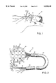
- FIG. 1 is a perspective view of a patient during minimally invasive heart surgery
- FIG. 2 is a top plan view of the organ manipulation device according to the present invention.
- FIG. 3 is a partial, perspective view of the organ manipulation device with the pod in a collapsed, rolled-up state
- FIG. 4 is a side view of the organ manipulation device in its operative position
- FIG. 5 is a partial, sectional view of the pod of the manipulation device taken along lines 5--5 of FIG. 2;
- FIG. 6 is a partial, sectional view of the pod similar to FIG. 5, showing a second embodiment of the pod;
- FIG. 7 is a schematic view of a pressure sensor incorporated into the organ manipulation device according to the invention.
- FIG. 8 is a flow chart of one embodiment of a program for controlling the fluid pressure supply to the organ manipulation device.
- multiple small incisions are made in the chest wall for the receipt of surgical instruments.
- two small incisions are made in the chest wall 10 of a patient 12 at different interstitial rib positions, while a third incision is made just below the sternum.
- a first trocar 14 is inserted into the first incision at one of the interstices while a second trocar 16 is inserted into the second incision at another of the interstices.
- the first and second incisions are made on opposite sides of the sternum.
- a third trocar is inserted into the third incision just below the sternum.
- each trocar is conventional and has a boss 22 depending from a flange 20.
- the flange 20 is larger in diameter than boss 22, so that when the trocar is installed by pushing the boss through the incision at the interstice between the ribs, the flange will rest on the patient's outer epithelial layer of the external integument.
- the boss 22 is sufficiently long to fit between the ribs, so that when the trocar is installed, the ribs are spread apart.
- a central aperture (not shown) extends through each trocar for the reception of surgical instruments, tubes, etc.
- conventional devices such as an endoscope, a first surgical instrument, and a secondary instrument, as represented generically by the first cannula 24, second cannula 26, and third cannula 28, are inserted as needed into the central apertures of the several trocars.
- a heart elevator and manipulator 30 for use in minimally invasive surgery comprises a pod 32 having a plurality of separately inflatable/deflatable pillows 34 spaced over at least the upper surface 36 of pod 32.
- the pod is preferably formed of two separate polymeric layers and sealed at the outer peripheral edge 38 and also sealed along partitions 40 to form the several individual pillows 34.
- the layers may be sealed together through any well-known technique such as heat-sealing or ultrasonic welding.
- the pod is sufficiently flexible to permit it to be rolled up as shown in FIG. 3.
- Each pillow 34 forms a separately sealed chamber which is selectively inflatable/deflatable independent of any other pillow.
- the chamber of each pillow is in fluid communication with a fluid supply line or lumen 42 extending therefrom.
- the several lumens 42 extend from the pod 32 closely adjacent one another and are received in the distal end 41 of a conventional cannula 44.
- the lumens extend through the proximal end 45 of the cannula 44 and terminate at a stop-cock valve 46.
- Valve 46 is a well-known valve having a manual actuator 48 to open or close fluid communication between the lumen to which it is attached and a conduit 50.
- the conduit 50 has an internal bore sized to receive a common syringe (not shown) or other conventional fluid supply source.
- the valve associated with each supply line permits fluid to be selectively introduced into or withdrawn from any number of selected chambers by manipulating the valves and syringes to thereby selectively inflate or deflate the selected pillow chambers.
- pod 32 is initially in a rolled, collapsed state as shown in FIG. 3.
- the rolled pod diameter is smaller than the trocar central opening so that the pod is then inserted through trocar 18 along with a portion of cannula 44 until the pod is fully received in the body cavity.
- the elasticity of the pod will naturally cause the pod to unroll as it clears trocar 18 to an open state as shown in FIGS. 2 and 4.
- the pod is unrolled, it is positioned adjacent to the heart, preferably beneath the heart.
- saline solution, air, or some other acceptable fluid or gas is injected from the fluid supply through one or a plurality of selected valves 46 to selectively fill one or more of the corresponding pillows 34.
- the pillows can be partially or completely filled to create the desired manipulation of the heart.
- Valves 36 are initially closed and must be opened by manipulating actuator 48 before injecting the saline solution.
- the pillows 34 begin to expand between the body cavity and heart 52 to position the heart as desired.
- the heart 52 can be simultaneously rotated about two orthogonal axes as shown by arrows 54, 56 in FIG. 4.
- the valves are again closed to prevent saline leakage.
- hydraulic pressure from the saline solution in the selected pillows and lumens will keep the heart in its new position until the valves are opened and the syringes are manipulated.
- the pod 32 can be withdrawn by grasping lumens 42 and pulling pod 32 out through the trocar.
- Pod 32 is sufficiently flexible to permit its withdrawal through the trocar.
- the rounded outer perimeter 38 of the pod eases the withdrawal through the trocar.
- An alternate method of inserting and positioning the pod 32 in a position to manipulate the heart includes rolling the pod sufficiently tight to telescopically fit within cannula 44.
- the cannula 44 and pod 32 are then inserted as a unit through the trocar until the unit is positioned between the body cavity and the heart 52.
- the lumens 42 and cannula 44 are then grasped while sliding the cannula with respect to the lumens back through the trocar until pod 32 is completely exposed.
- Pod 32 will naturally unroll to the open state. If necessary, saline solution can be injected into selected pillows to help the pod unroll.
- the pillows of the first embodiment are selectively inflated to varying levels to provide extensive control to the surgeon in repositioning or manipulating the heart.
- the pillows 34 are adapted to expand upwardly from the upper surface 36.
- FIG. 6 shows a second embodiment of the pod 56 in which the pillows 58 are adapted to expand from both the top and bottom surfaces 60, 62, respectively, of the pod 56.
- the size of the pillows can be varied so that additional control in manipulating the balloon is achieved.
- the pod 32 is shown in FIG. 2 having a generally circular configuration. However, it is within the scope of the invention for pod 32 to have other configurations including, but not limited to, square, rectangular, oval, crescent shaped and "U" shaped. In the embodiments having a crescent or "U" shaped configuration, the pod 32 may fit around anatomical features and thereby allow the most efficient positioning of the pod 32. In some cases, the use of the crescent of "U" shaped configuration will allow a pod 32 to be used where other shapes could not be accommodated.
- pillows 34 to have varying heights to conform to certain anatomical areas of the heart and to allow certain areas of the heart to be moved more than others by contact with specific pillows 34.
- pillows 34 could be selectively inflatable in decreasing heights across the face of pod 32.
- pillows 34 could be selectively inflatable with a maximum height around the peripheral edge 38 of pod 32 and a minimum height near the center of pod 32.
- pillows 34 could be selectively inflatable with a minimum height around the peripheral edge 38 of pod 32 and a maximum height near the center of pod 32.
- a pressure sensor 64 is attached to at least one lumen 42.
- pressure sensor 64 is attached to lumen 42 at conduit 50 so as not to interfere with the presentation of pressurized fluid to lumen 42.
- Pressure sensor 64 may also be placed within a pillow 34 or near a pillow 34 along lumen 42 on pod 32.
- Pressure sensor 64 is electronically attached to a microprocessor 66 through line 68.
- Microprocessor 66 is attached to a pressurized fluid source 70 through line 72.
- Pressurized fluid source 70 may be a control valve placed between a source of pressurized fluid and lumen 42 so that the control valve modulates the fluid pressure supplied to lumen 42 in response to commands from microprocessor 66.
- pressurized fluid source 70 may be a pump that is modulated by command signals from microprocessor 66 to provide fluid at different pressures to lumen 42.
- the combination of pressure sensor 64, microprocessor 66, and pressurized fluid source 70 combine to maintain a near constant pressure in lumen 42. Without such a system, as the heart beats, it pushes against a pillow 34 and increases the fluid pressure within pillow 34. As the pressure in pillow 34 increases, pillow 34 becomes more rigid. As a result, the beating heart pushes against and away from pillow 34. Therefore, the beating motion of the heart is accentuated.
- the system of the combination of pressure sensor 64, microprocessor 66, and pressurized fluid source 70 acts to increase or decrease the pressure in pillow 34 resulting from the beating motion of the heart to maintain a near constant pressure within pillow 34.
- the pressure is sensed by pressure sensor 64 and is communicated to microprocessor 66.
- Microprocessor 66 detects an increase in pressure in pillow 34 and directs pressurized fluid source 70 to decrease the pressure in pillow 34. This allows pillow 34 to "give" against the push of the beating heart so that the heart does not press against and move away from pod 32.
- microprocessor 66 detects that the pressure detected by pressure sensor 64 is decreasing because the beating heart is contracting, microprocessor 66 directs pressurized fluid source 70 to increase the pressure in pillows 34, thereby more fully inflating pillows 34. This keeps the bulk of the heart from moving closer to pod 32. In this way, the beating heart is always in contact with pod 32 and is kept in essentially the same position despite the fact that the heart is moving while beating.
- FIG. 8 shows a flow chart of a possible program to be run by microprocessor 66 to implement the invention described above.
- the pressure detected by pressure sensor 64 is presented to microprocessor 66.
- the program begins at start block 74. From start block 74, the program moves to decision block 76.
- Decision block 76 asks whether the pressure currently sensed by pressure sensor 64 is the same as a set pressure.
- the set pressure may be an average pressure of the actual pressures sensed by pressure sensor 64 over time or may be a predetermined pressure. If, in decision block 76, the pressure currently sensed is the same as the set pressure, the program loops to the start block 74 to begin the program again.
- decision block 76 If, in decision block 76, the pressure currently sensed is not the same as a set pressure, the program passes to decision block 78. Decision block 78 asks whether the pressure currently sensed by pressure sensor 64 is higher than the set pressure. If the answer is yes, the program passes to process block 80 which directs the pressurized fluid source 70 to decrease the fluid pressure sent to pillow 34. The program then passes to start block 74 to begin the program again.
- Process block 82 directs the pressurized fluid source 70 to increase the pressure sent to pillow 34.
- the program then passes to start block 74 to begin the program again.
- the preferred application of the manipulation device according to the invention is for use in minimally invasive heart surgical procedures.
- the manipulation device according to the invention can be used in any surgical procedure, minimally invasive or conventional, in which selective control or manipulation of an organ or tissue is desired.
- the manipulation device could be adapted for use in laparoscopic surgical procedures.
Abstract
Description
Claims (16)
Priority Applications (7)
| Application Number | Priority Date | Filing Date | Title |
|---|---|---|---|
| US08/637,974 US6036640A (en) | 1996-04-29 | 1996-04-29 | Device and method for repositioning the heart during surgery |
| CA002249986A CA2249986A1 (en) | 1996-04-29 | 1997-02-05 | Device and method for repositioning the heart during surgery |
| DE69733310T DE69733310T2 (en) | 1996-04-29 | 1997-02-05 | DEVICE FOR POSITIONING THE HEART DURING OPERATION |
| PCT/US1997/001984 WO1997040751A1 (en) | 1996-04-29 | 1997-02-05 | Device and method for repositioning the heart during surgery |
| AU21190/97A AU710409B2 (en) | 1996-04-29 | 1997-02-05 | Device and method for repositioning the heart during surgery |
| EP97906520A EP0898462B1 (en) | 1996-04-29 | 1997-02-05 | Device for repositioning the heart during surgery |
| JP09538855A JP2000508946A (en) | 1996-04-29 | 1997-02-05 | Apparatus and method for performing heart reposition during surgery |
Applications Claiming Priority (1)
| Application Number | Priority Date | Filing Date | Title |
|---|---|---|---|
| US08/637,974 US6036640A (en) | 1996-04-29 | 1996-04-29 | Device and method for repositioning the heart during surgery |
Publications (1)
| Publication Number | Publication Date |
|---|---|
| US6036640A true US6036640A (en) | 2000-03-14 |
Family
ID=24558130
Family Applications (1)
| Application Number | Title | Priority Date | Filing Date |
|---|---|---|---|
| US08/637,974 Expired - Lifetime US6036640A (en) | 1996-04-29 | 1996-04-29 | Device and method for repositioning the heart during surgery |
Country Status (7)
| Country | Link |
|---|---|
| US (1) | US6036640A (en) |
| EP (1) | EP0898462B1 (en) |
| JP (1) | JP2000508946A (en) |
| AU (1) | AU710409B2 (en) |
| CA (1) | CA2249986A1 (en) |
| DE (1) | DE69733310T2 (en) |
| WO (1) | WO1997040751A1 (en) |
Cited By (49)
| Publication number | Priority date | Publication date | Assignee | Title |
|---|---|---|---|---|
| US6319193B1 (en) * | 1998-06-05 | 2001-11-20 | Sumitomo Bakelite Company Ltd | Auxiliary device for pulsatile coronary artery bypass |
| US6371910B1 (en) * | 1997-10-16 | 2002-04-16 | General Surgical Innovations, Inc. | Inflatable manipulator for organ positioning during surgery |
| US20030105481A1 (en) * | 1996-08-01 | 2003-06-05 | Revivant Corporation | Minimally invasive direct cardiac massage device and method |
| US6706064B1 (en) * | 1997-06-28 | 2004-03-16 | Anson Medical Limited | Expandable device |
| US20040254625A1 (en) * | 2003-06-13 | 2004-12-16 | Trivascular, Inc. | Inflatable implant |
| US20070233273A1 (en) * | 2003-05-26 | 2007-10-04 | Connell Anthony F | Differential Tissue Expander Implant |
| US7369901B1 (en) | 2004-02-11 | 2008-05-06 | Pacesetter, Inc. | Myocardial lead and lead system |
| US20090062618A1 (en) * | 2007-08-29 | 2009-03-05 | Ethicon Endo-Surgery, Inc. | Tissue retractors |
| US20090131932A1 (en) * | 2007-11-21 | 2009-05-21 | Vakharia Omar J | Bipolar forceps having a cutting element |
| US20090137984A1 (en) * | 2007-11-26 | 2009-05-28 | Ethicon Endo-Surgery, Inc. | Tissue retractors |
| US20090137877A1 (en) * | 2007-11-26 | 2009-05-28 | Ethicon Endo-Surgery, Inc. | Tissue retractors |
| US20110105850A1 (en) * | 2009-11-05 | 2011-05-05 | Ethicon Endo-Surgery, Inc. | Vaginal entry surgical devices, kit, system, and method |
| US20110112434A1 (en) * | 2009-11-06 | 2011-05-12 | Ethicon Endo-Surgery, Inc. | Kits and procedures for natural orifice translumenal endoscopic surgery |
| US20110124964A1 (en) * | 2007-10-31 | 2011-05-26 | Ethicon Endo-Surgery, Inc. | Methods for closing a gastrotomy |
| US20110196060A1 (en) * | 2005-04-01 | 2011-08-11 | Trivascular, Inc. | Non-degradable, low swelling, water soluble radiopaque hydrogel polymer |
| US8066755B2 (en) | 2007-09-26 | 2011-11-29 | Trivascular, Inc. | System and method of pivoted stent deployment |
| US8083789B2 (en) | 2007-11-16 | 2011-12-27 | Trivascular, Inc. | Securement assembly and method for expandable endovascular device |
| US8226701B2 (en) | 2007-09-26 | 2012-07-24 | Trivascular, Inc. | Stent and delivery system for deployment thereof |
| US8328861B2 (en) | 2007-11-16 | 2012-12-11 | Trivascular, Inc. | Delivery system and method for bifurcated graft |
| US20130090666A1 (en) * | 2011-10-06 | 2013-04-11 | Ethicon Endo-Surgery, Inc. | Vacuum assisted tissue manipulation devices and surgical methods |
| US8663309B2 (en) | 2007-09-26 | 2014-03-04 | Trivascular, Inc. | Asymmetric stent apparatus and method |
| US8758235B2 (en) | 2011-07-13 | 2014-06-24 | Cook Medical Technologies Llc | Foldable surgical retractor |
| WO2014096252A1 (en) | 2012-12-20 | 2014-06-26 | Aesculap Ag | Surgical positioning instrument for supporting and holding organs |
| US8992595B2 (en) | 2012-04-04 | 2015-03-31 | Trivascular, Inc. | Durable stent graft with tapered struts and stable delivery methods and devices |
| US9011431B2 (en) | 2009-01-12 | 2015-04-21 | Ethicon Endo-Surgery, Inc. | Electrical ablation devices |
| US9078662B2 (en) | 2012-07-03 | 2015-07-14 | Ethicon Endo-Surgery, Inc. | Endoscopic cap electrode and method for using the same |
| US9233241B2 (en) | 2011-02-28 | 2016-01-12 | Ethicon Endo-Surgery, Inc. | Electrical ablation devices and methods |
| US9254169B2 (en) | 2011-02-28 | 2016-02-09 | Ethicon Endo-Surgery, Inc. | Electrical ablation devices and methods |
| US9277957B2 (en) | 2012-08-15 | 2016-03-08 | Ethicon Endo-Surgery, Inc. | Electrosurgical devices and methods |
| US9314620B2 (en) | 2011-02-28 | 2016-04-19 | Ethicon Endo-Surgery, Inc. | Electrical ablation devices and methods |
| US9375268B2 (en) | 2007-02-15 | 2016-06-28 | Ethicon Endo-Surgery, Inc. | Electroporation ablation apparatus, system, and method |
| US9427255B2 (en) | 2012-05-14 | 2016-08-30 | Ethicon Endo-Surgery, Inc. | Apparatus for introducing a steerable camera assembly into a patient |
| US9498363B2 (en) | 2012-04-06 | 2016-11-22 | Trivascular, Inc. | Delivery catheter for endovascular device |
| US9545290B2 (en) | 2012-07-30 | 2017-01-17 | Ethicon Endo-Surgery, Inc. | Needle probe guide |
| US9572623B2 (en) | 2012-08-02 | 2017-02-21 | Ethicon Endo-Surgery, Inc. | Reusable electrode and disposable sheath |
| US9883910B2 (en) | 2011-03-17 | 2018-02-06 | Eticon Endo-Surgery, Inc. | Hand held surgical device for manipulating an internal magnet assembly within a patient |
| US10092291B2 (en) | 2011-01-25 | 2018-10-09 | Ethicon Endo-Surgery, Inc. | Surgical instrument with selectively rigidizable features |
| US10098527B2 (en) | 2013-02-27 | 2018-10-16 | Ethidcon Endo-Surgery, Inc. | System for performing a minimally invasive surgical procedure |
| US10098691B2 (en) | 2009-12-18 | 2018-10-16 | Ethicon Endo-Surgery, Inc. | Surgical instrument comprising an electrode |
| US10105141B2 (en) | 2008-07-14 | 2018-10-23 | Ethicon Endo-Surgery, Inc. | Tissue apposition clip application methods |
| US10159557B2 (en) | 2007-10-04 | 2018-12-25 | Trivascular, Inc. | Modular vascular graft for low profile percutaneous delivery |
| US10314649B2 (en) | 2012-08-02 | 2019-06-11 | Ethicon Endo-Surgery, Inc. | Flexible expandable electrode and method of intraluminal delivery of pulsed power |
| US10314603B2 (en) | 2008-11-25 | 2019-06-11 | Ethicon Llc | Rotational coupling device for surgical instrument with flexible actuators |
| US10779882B2 (en) | 2009-10-28 | 2020-09-22 | Ethicon Endo-Surgery, Inc. | Electrical ablation devices |
| US20210022722A1 (en) * | 2018-02-06 | 2021-01-28 | ProSys International Limited | Surgical tool |
| US10959761B2 (en) | 2015-09-18 | 2021-03-30 | Ortho-Space Ltd. | Intramedullary fixated subacromial spacers |
| US11033398B2 (en) | 2007-03-15 | 2021-06-15 | Ortho-Space Ltd. | Shoulder implant for simulating a bursa |
| US11045981B2 (en) | 2017-01-30 | 2021-06-29 | Ortho-Space Ltd. | Processing machine and methods for processing dip-molded articles |
| US11826228B2 (en) | 2011-10-18 | 2023-11-28 | Stryker European Operations Limited | Prosthetic devices |
Families Citing this family (28)
| Publication number | Priority date | Publication date | Assignee | Title |
|---|---|---|---|---|
| US7027869B2 (en) | 1998-01-07 | 2006-04-11 | Asthmatx, Inc. | Method for treating an asthma attack |
| US7992572B2 (en) | 1998-06-10 | 2011-08-09 | Asthmatx, Inc. | Methods of evaluating individuals having reversible obstructive pulmonary disease |
| US6634363B1 (en) | 1997-04-07 | 2003-10-21 | Broncus Technologies, Inc. | Methods of treating lungs having reversible obstructive pulmonary disease |
| US6123725A (en) * | 1997-07-11 | 2000-09-26 | A-Med Systems, Inc. | Single port cardiac support apparatus |
| US6395026B1 (en) | 1998-05-15 | 2002-05-28 | A-Med Systems, Inc. | Apparatus and methods for beating heart bypass surgery |
| US6532964B2 (en) * | 1997-07-11 | 2003-03-18 | A-Med Systems, Inc. | Pulmonary and circulatory blood flow support devices and methods for heart surgery procedures |
| US7921855B2 (en) | 1998-01-07 | 2011-04-12 | Asthmatx, Inc. | Method for treating an asthma attack |
| US7198635B2 (en) | 2000-10-17 | 2007-04-03 | Asthmatx, Inc. | Modification of airways by application of energy |
| US8181656B2 (en) | 1998-06-10 | 2012-05-22 | Asthmatx, Inc. | Methods for treating airways |
| DE19841652A1 (en) * | 1998-09-11 | 2000-03-30 | Aesculap Ag & Co Kg | Flat retention element for body parts |
| DE19947885B4 (en) * | 1998-10-05 | 2009-04-09 | Cardiothoracic Systems, Inc., Cupertino | Device for positioning the heart during cardiac surgery while maintaining cardiac output |
| US8241274B2 (en) | 2000-01-19 | 2012-08-14 | Medtronic, Inc. | Method for guiding a medical device |
| US8251070B2 (en) | 2000-03-27 | 2012-08-28 | Asthmatx, Inc. | Methods for treating airways |
| US7104987B2 (en) | 2000-10-17 | 2006-09-12 | Asthmatx, Inc. | Control system and process for application of energy to airway walls and other mediums |
| US20040226556A1 (en) | 2003-05-13 | 2004-11-18 | Deem Mark E. | Apparatus for treating asthma using neurotoxin |
| JP2008259701A (en) * | 2007-04-12 | 2008-10-30 | Olympus Corp | Apparatus inserted into living body |
| US8483831B1 (en) | 2008-02-15 | 2013-07-09 | Holaira, Inc. | System and method for bronchial dilation |
| WO2009137819A1 (en) | 2008-05-09 | 2009-11-12 | Innovative Pulmonary Solutions, Inc. | Systems, assemblies, and methods for treating a bronchial tree |
| WO2011056684A2 (en) | 2009-10-27 | 2011-05-12 | Innovative Pulmonary Solutions, Inc. | Delivery devices with coolable energy emitting assemblies |
| US8911439B2 (en) | 2009-11-11 | 2014-12-16 | Holaira, Inc. | Non-invasive and minimally invasive denervation methods and systems for performing the same |
| CN106618731B (en) | 2009-11-11 | 2020-08-07 | 努瓦拉公司 | Systems, devices, and methods for treating tissue and controlling stenosis |
| EP3868321B1 (en) | 2012-06-04 | 2022-11-16 | Boston Scientific Scimed, Inc. | Systems for treating tissue of a passageway within a body |
| US9592086B2 (en) | 2012-07-24 | 2017-03-14 | Boston Scientific Scimed, Inc. | Electrodes for tissue treatment |
| US9272132B2 (en) | 2012-11-02 | 2016-03-01 | Boston Scientific Scimed, Inc. | Medical device for treating airways and related methods of use |
| US9283374B2 (en) | 2012-11-05 | 2016-03-15 | Boston Scientific Scimed, Inc. | Devices and methods for delivering energy to body lumens |
| US9398933B2 (en) | 2012-12-27 | 2016-07-26 | Holaira, Inc. | Methods for improving drug efficacy including a combination of drug administration and nerve modulation |
| US10478247B2 (en) | 2013-08-09 | 2019-11-19 | Boston Scientific Scimed, Inc. | Expandable catheter and related methods of manufacture and use |
| US10842631B2 (en) | 2017-02-23 | 2020-11-24 | The Cleveland Clinic Foundation | Transcatheter cardiac de-airing system |
Citations (15)
| Publication number | Priority date | Publication date | Assignee | Title |
|---|---|---|---|---|
| US4637377A (en) * | 1985-09-20 | 1987-01-20 | Loop Floyd D | Pillow or support member for surgical use |
| US4651717A (en) * | 1985-04-04 | 1987-03-24 | Dow Corning Corporation | Multiple envelope tissue expander device |
| US4984564A (en) * | 1989-09-27 | 1991-01-15 | Frank Yuen | Surgical retractor device |
| US5158571A (en) * | 1990-03-09 | 1992-10-27 | Picha George J | Tissue expander and method for expanding tissue |
| US5163949A (en) * | 1990-03-02 | 1992-11-17 | Bonutti Peter M | Fluid operated retractors |
| US5211162A (en) * | 1991-07-09 | 1993-05-18 | Pneu-Mobility, Inc. | Apparatus and method for massaging the back utilizing pneumatic cushions |
| WO1993010850A1 (en) * | 1991-11-25 | 1993-06-10 | Advanced Surgical, Inc. | Self-deploying structures and method of making |
| US5256139A (en) * | 1991-01-03 | 1993-10-26 | Kamran Ghodsian | Intra-abdominal organ manipulator, irrigator, aspirator and method |
| EP0573273A2 (en) * | 1992-06-02 | 1993-12-08 | GENERAL SURGICAL INNOVATION, Inc. | Apparatus and method for developing an anatomic space for laparoscopic hernia repair and patch for use therewith |
| US5318586A (en) * | 1993-01-19 | 1994-06-07 | Erkan Ereren | Laparoscopic and thoracoscopic expandable instruments |
| US5361752A (en) * | 1991-05-29 | 1994-11-08 | Origin Medsystems, Inc. | Retraction apparatus and methods for endoscopic surgery |
| US5439476A (en) * | 1993-02-04 | 1995-08-08 | Trigonon, Inc. | Inflatable laparoscopic retractor |
| WO1996000033A1 (en) * | 1994-06-24 | 1996-01-04 | Heartport, Inc. | Endoscopic vascular clamping system and method |
| US5520609A (en) * | 1991-05-29 | 1996-05-28 | Origin Medsystems, Inc. | Apparatus and method for peritoneal retraction |
| US5613937A (en) * | 1993-02-22 | 1997-03-25 | Heartport, Inc. | Method of retracting heart tissue in closed-chest heart surgery using endo-scopic retraction |
Family Cites Families (1)
| Publication number | Priority date | Publication date | Assignee | Title |
|---|---|---|---|---|
| DE4317752C2 (en) * | 1993-05-27 | 1997-10-16 | Peter Dr Feindt | Device for supporting cardiac function |
-
1996
- 1996-04-29 US US08/637,974 patent/US6036640A/en not_active Expired - Lifetime
-
1997
- 1997-02-05 DE DE69733310T patent/DE69733310T2/en not_active Expired - Lifetime
- 1997-02-05 EP EP97906520A patent/EP0898462B1/en not_active Expired - Lifetime
- 1997-02-05 CA CA002249986A patent/CA2249986A1/en not_active Abandoned
- 1997-02-05 AU AU21190/97A patent/AU710409B2/en not_active Ceased
- 1997-02-05 WO PCT/US1997/001984 patent/WO1997040751A1/en active IP Right Grant
- 1997-02-05 JP JP09538855A patent/JP2000508946A/en active Pending
Patent Citations (17)
| Publication number | Priority date | Publication date | Assignee | Title |
|---|---|---|---|---|
| US4651717A (en) * | 1985-04-04 | 1987-03-24 | Dow Corning Corporation | Multiple envelope tissue expander device |
| US4637377A (en) * | 1985-09-20 | 1987-01-20 | Loop Floyd D | Pillow or support member for surgical use |
| US4984564A (en) * | 1989-09-27 | 1991-01-15 | Frank Yuen | Surgical retractor device |
| US5163949A (en) * | 1990-03-02 | 1992-11-17 | Bonutti Peter M | Fluid operated retractors |
| US5158571A (en) * | 1990-03-09 | 1992-10-27 | Picha George J | Tissue expander and method for expanding tissue |
| US5256139A (en) * | 1991-01-03 | 1993-10-26 | Kamran Ghodsian | Intra-abdominal organ manipulator, irrigator, aspirator and method |
| US5425357A (en) * | 1991-05-29 | 1995-06-20 | Origin Medsystems, Inc. | Inflatable retraction devices for use in laparoscopic surgery |
| US5361752A (en) * | 1991-05-29 | 1994-11-08 | Origin Medsystems, Inc. | Retraction apparatus and methods for endoscopic surgery |
| US5520609A (en) * | 1991-05-29 | 1996-05-28 | Origin Medsystems, Inc. | Apparatus and method for peritoneal retraction |
| US5211162A (en) * | 1991-07-09 | 1993-05-18 | Pneu-Mobility, Inc. | Apparatus and method for massaging the back utilizing pneumatic cushions |
| WO1993010850A1 (en) * | 1991-11-25 | 1993-06-10 | Advanced Surgical, Inc. | Self-deploying structures and method of making |
| US5308327A (en) * | 1991-11-25 | 1994-05-03 | Advanced Surgical Inc. | Self-deployed inflatable retractor |
| EP0573273A2 (en) * | 1992-06-02 | 1993-12-08 | GENERAL SURGICAL INNOVATION, Inc. | Apparatus and method for developing an anatomic space for laparoscopic hernia repair and patch for use therewith |
| US5318586A (en) * | 1993-01-19 | 1994-06-07 | Erkan Ereren | Laparoscopic and thoracoscopic expandable instruments |
| US5439476A (en) * | 1993-02-04 | 1995-08-08 | Trigonon, Inc. | Inflatable laparoscopic retractor |
| US5613937A (en) * | 1993-02-22 | 1997-03-25 | Heartport, Inc. | Method of retracting heart tissue in closed-chest heart surgery using endo-scopic retraction |
| WO1996000033A1 (en) * | 1994-06-24 | 1996-01-04 | Heartport, Inc. | Endoscopic vascular clamping system and method |
Non-Patent Citations (2)
| Title |
|---|
| PCT/ISA/220 Notification of Transmittal of International Search Report, Jul. 11, 1997. * |
| PCT/ISA/220--Notification of Transmittal of International Search Report, Jul. 11, 1997. |
Cited By (78)
| Publication number | Priority date | Publication date | Assignee | Title |
|---|---|---|---|---|
| US20040167563A1 (en) * | 1996-08-01 | 2004-08-26 | Fogarty Thomas J. | Minimally invasive direct cardiac massage device and method |
| US20030105481A1 (en) * | 1996-08-01 | 2003-06-05 | Revivant Corporation | Minimally invasive direct cardiac massage device and method |
| US6699259B2 (en) * | 1996-08-01 | 2004-03-02 | Revivant Corporation | Minimally invasive direct cardiac massage device and method |
| US6706064B1 (en) * | 1997-06-28 | 2004-03-16 | Anson Medical Limited | Expandable device |
| US20040167614A1 (en) * | 1997-06-28 | 2004-08-26 | Anson Antony Walter | Expandable device |
| US6371910B1 (en) * | 1997-10-16 | 2002-04-16 | General Surgical Innovations, Inc. | Inflatable manipulator for organ positioning during surgery |
| US6319193B1 (en) * | 1998-06-05 | 2001-11-20 | Sumitomo Bakelite Company Ltd | Auxiliary device for pulsatile coronary artery bypass |
| US20070233273A1 (en) * | 2003-05-26 | 2007-10-04 | Connell Anthony F | Differential Tissue Expander Implant |
| US11000288B2 (en) | 2003-06-13 | 2021-05-11 | Trivascular, Inc. | Inflatable implant |
| US20040254625A1 (en) * | 2003-06-13 | 2004-12-16 | Trivascular, Inc. | Inflatable implant |
| US10201350B2 (en) | 2003-06-13 | 2019-02-12 | Trivascular, Inc. | Inflatable implant |
| US7632291B2 (en) | 2003-06-13 | 2009-12-15 | Trivascular2, Inc. | Inflatable implant |
| US7369901B1 (en) | 2004-02-11 | 2008-05-06 | Pacesetter, Inc. | Myocardial lead and lead system |
| US20110196060A1 (en) * | 2005-04-01 | 2011-08-11 | Trivascular, Inc. | Non-degradable, low swelling, water soluble radiopaque hydrogel polymer |
| US11298444B2 (en) | 2005-04-01 | 2022-04-12 | Trivascular, Inc. | Non-degradable, low swelling, water soluble radiopaque hydrogel polymer |
| US9308301B2 (en) | 2005-04-01 | 2016-04-12 | Trivascular, Inc. | Non-degradable, low swelling, water soluble radiopaque hydrogel polymer |
| US10478248B2 (en) | 2007-02-15 | 2019-11-19 | Ethicon Llc | Electroporation ablation apparatus, system, and method |
| US9375268B2 (en) | 2007-02-15 | 2016-06-28 | Ethicon Endo-Surgery, Inc. | Electroporation ablation apparatus, system, and method |
| US11033398B2 (en) | 2007-03-15 | 2021-06-15 | Ortho-Space Ltd. | Shoulder implant for simulating a bursa |
| US20090062618A1 (en) * | 2007-08-29 | 2009-03-05 | Ethicon Endo-Surgery, Inc. | Tissue retractors |
| US8465515B2 (en) | 2007-08-29 | 2013-06-18 | Ethicon Endo-Surgery, Inc. | Tissue retractors |
| US8066755B2 (en) | 2007-09-26 | 2011-11-29 | Trivascular, Inc. | System and method of pivoted stent deployment |
| US8226701B2 (en) | 2007-09-26 | 2012-07-24 | Trivascular, Inc. | Stent and delivery system for deployment thereof |
| US8663309B2 (en) | 2007-09-26 | 2014-03-04 | Trivascular, Inc. | Asymmetric stent apparatus and method |
| US10159557B2 (en) | 2007-10-04 | 2018-12-25 | Trivascular, Inc. | Modular vascular graft for low profile percutaneous delivery |
| US10682222B2 (en) | 2007-10-04 | 2020-06-16 | Trivascular, Inc. | Modular vascular graft for low profile percutaneous delivery |
| US20110124964A1 (en) * | 2007-10-31 | 2011-05-26 | Ethicon Endo-Surgery, Inc. | Methods for closing a gastrotomy |
| US8939897B2 (en) | 2007-10-31 | 2015-01-27 | Ethicon Endo-Surgery, Inc. | Methods for closing a gastrotomy |
| US8328861B2 (en) | 2007-11-16 | 2012-12-11 | Trivascular, Inc. | Delivery system and method for bifurcated graft |
| US8083789B2 (en) | 2007-11-16 | 2011-12-27 | Trivascular, Inc. | Securement assembly and method for expandable endovascular device |
| US8579897B2 (en) | 2007-11-21 | 2013-11-12 | Ethicon Endo-Surgery, Inc. | Bipolar forceps |
| US20090131932A1 (en) * | 2007-11-21 | 2009-05-21 | Vakharia Omar J | Bipolar forceps having a cutting element |
| US8517931B2 (en) | 2007-11-26 | 2013-08-27 | Ethicon Endo-Surgery, Inc. | Tissue retractors |
| US20090137984A1 (en) * | 2007-11-26 | 2009-05-28 | Ethicon Endo-Surgery, Inc. | Tissue retractors |
| US20090137877A1 (en) * | 2007-11-26 | 2009-05-28 | Ethicon Endo-Surgery, Inc. | Tissue retractors |
| US8128559B2 (en) | 2007-11-26 | 2012-03-06 | Ethicon Endo-Surgery, Inc. | Tissue retractors |
| US11399834B2 (en) | 2008-07-14 | 2022-08-02 | Cilag Gmbh International | Tissue apposition clip application methods |
| US10105141B2 (en) | 2008-07-14 | 2018-10-23 | Ethicon Endo-Surgery, Inc. | Tissue apposition clip application methods |
| US10314603B2 (en) | 2008-11-25 | 2019-06-11 | Ethicon Llc | Rotational coupling device for surgical instrument with flexible actuators |
| US9011431B2 (en) | 2009-01-12 | 2015-04-21 | Ethicon Endo-Surgery, Inc. | Electrical ablation devices |
| US10004558B2 (en) | 2009-01-12 | 2018-06-26 | Ethicon Endo-Surgery, Inc. | Electrical ablation devices |
| US10779882B2 (en) | 2009-10-28 | 2020-09-22 | Ethicon Endo-Surgery, Inc. | Electrical ablation devices |
| US20110105850A1 (en) * | 2009-11-05 | 2011-05-05 | Ethicon Endo-Surgery, Inc. | Vaginal entry surgical devices, kit, system, and method |
| US8608652B2 (en) | 2009-11-05 | 2013-12-17 | Ethicon Endo-Surgery, Inc. | Vaginal entry surgical devices, kit, system, and method |
| US20110112434A1 (en) * | 2009-11-06 | 2011-05-12 | Ethicon Endo-Surgery, Inc. | Kits and procedures for natural orifice translumenal endoscopic surgery |
| US10098691B2 (en) | 2009-12-18 | 2018-10-16 | Ethicon Endo-Surgery, Inc. | Surgical instrument comprising an electrode |
| US10092291B2 (en) | 2011-01-25 | 2018-10-09 | Ethicon Endo-Surgery, Inc. | Surgical instrument with selectively rigidizable features |
| US9254169B2 (en) | 2011-02-28 | 2016-02-09 | Ethicon Endo-Surgery, Inc. | Electrical ablation devices and methods |
| US10258406B2 (en) | 2011-02-28 | 2019-04-16 | Ethicon Llc | Electrical ablation devices and methods |
| US9233241B2 (en) | 2011-02-28 | 2016-01-12 | Ethicon Endo-Surgery, Inc. | Electrical ablation devices and methods |
| US10278761B2 (en) | 2011-02-28 | 2019-05-07 | Ethicon Llc | Electrical ablation devices and methods |
| US9314620B2 (en) | 2011-02-28 | 2016-04-19 | Ethicon Endo-Surgery, Inc. | Electrical ablation devices and methods |
| US9883910B2 (en) | 2011-03-17 | 2018-02-06 | Eticon Endo-Surgery, Inc. | Hand held surgical device for manipulating an internal magnet assembly within a patient |
| US8758235B2 (en) | 2011-07-13 | 2014-06-24 | Cook Medical Technologies Llc | Foldable surgical retractor |
| US20130090666A1 (en) * | 2011-10-06 | 2013-04-11 | Ethicon Endo-Surgery, Inc. | Vacuum assisted tissue manipulation devices and surgical methods |
| US11826228B2 (en) | 2011-10-18 | 2023-11-28 | Stryker European Operations Limited | Prosthetic devices |
| US8992595B2 (en) | 2012-04-04 | 2015-03-31 | Trivascular, Inc. | Durable stent graft with tapered struts and stable delivery methods and devices |
| US9498363B2 (en) | 2012-04-06 | 2016-11-22 | Trivascular, Inc. | Delivery catheter for endovascular device |
| US9427255B2 (en) | 2012-05-14 | 2016-08-30 | Ethicon Endo-Surgery, Inc. | Apparatus for introducing a steerable camera assembly into a patient |
| US10206709B2 (en) | 2012-05-14 | 2019-02-19 | Ethicon Llc | Apparatus for introducing an object into a patient |
| US11284918B2 (en) | 2012-05-14 | 2022-03-29 | Cilag GmbH Inlernational | Apparatus for introducing a steerable camera assembly into a patient |
| US9078662B2 (en) | 2012-07-03 | 2015-07-14 | Ethicon Endo-Surgery, Inc. | Endoscopic cap electrode and method for using the same |
| US9788888B2 (en) | 2012-07-03 | 2017-10-17 | Ethicon Endo-Surgery, Inc. | Endoscopic cap electrode and method for using the same |
| US9545290B2 (en) | 2012-07-30 | 2017-01-17 | Ethicon Endo-Surgery, Inc. | Needle probe guide |
| US10492880B2 (en) | 2012-07-30 | 2019-12-03 | Ethicon Llc | Needle probe guide |
| US10314649B2 (en) | 2012-08-02 | 2019-06-11 | Ethicon Endo-Surgery, Inc. | Flexible expandable electrode and method of intraluminal delivery of pulsed power |
| US9572623B2 (en) | 2012-08-02 | 2017-02-21 | Ethicon Endo-Surgery, Inc. | Reusable electrode and disposable sheath |
| US9277957B2 (en) | 2012-08-15 | 2016-03-08 | Ethicon Endo-Surgery, Inc. | Electrosurgical devices and methods |
| US10342598B2 (en) | 2012-08-15 | 2019-07-09 | Ethicon Llc | Electrosurgical system for delivering a biphasic waveform |
| US9788885B2 (en) | 2012-08-15 | 2017-10-17 | Ethicon Endo-Surgery, Inc. | Electrosurgical system energy source |
| DE102012112787A1 (en) | 2012-12-20 | 2014-06-26 | Aesculap Ag | Surgical positioning instrument for supporting and holding organs |
| WO2014096252A1 (en) | 2012-12-20 | 2014-06-26 | Aesculap Ag | Surgical positioning instrument for supporting and holding organs |
| US9743916B2 (en) | 2012-12-20 | 2017-08-29 | Aesculap Ag | Surgical positioning instrument for supporting and holding organs |
| US10098527B2 (en) | 2013-02-27 | 2018-10-16 | Ethidcon Endo-Surgery, Inc. | System for performing a minimally invasive surgical procedure |
| US11484191B2 (en) | 2013-02-27 | 2022-11-01 | Cilag Gmbh International | System for performing a minimally invasive surgical procedure |
| US10959761B2 (en) | 2015-09-18 | 2021-03-30 | Ortho-Space Ltd. | Intramedullary fixated subacromial spacers |
| US11045981B2 (en) | 2017-01-30 | 2021-06-29 | Ortho-Space Ltd. | Processing machine and methods for processing dip-molded articles |
| US20210022722A1 (en) * | 2018-02-06 | 2021-01-28 | ProSys International Limited | Surgical tool |
Also Published As
| Publication number | Publication date |
|---|---|
| AU2119097A (en) | 1997-11-19 |
| DE69733310D1 (en) | 2005-06-23 |
| WO1997040751A1 (en) | 1997-11-06 |
| AU710409B2 (en) | 1999-09-23 |
| JP2000508946A (en) | 2000-07-18 |
| EP0898462B1 (en) | 2005-05-18 |
| CA2249986A1 (en) | 1997-11-06 |
| EP0898462A1 (en) | 1999-03-03 |
| DE69733310T2 (en) | 2006-03-16 |
Similar Documents
| Publication | Publication Date | Title |
|---|---|---|
| US6036640A (en) | Device and method for repositioning the heart during surgery | |
| US10842631B2 (en) | Transcatheter cardiac de-airing system | |
| US6605037B1 (en) | Endoscopic inflatable retraction device | |
| US5823945A (en) | Endoscopic inflatable retraction device with additional inflatable chamber | |
| US5439476A (en) | Inflatable laparoscopic retractor | |
| US5454367A (en) | Method of using endoscopic inflatable retraction device with fluid tight elastomeric window | |
| US6015382A (en) | Inflatable manipulator for organ positioning during surgery and method of use | |
| US5527264A (en) | Methods of using endoscopic inflatable retraction devices | |
| US5836871A (en) | Method for lifting a body wall using an inflatable lifting apparatus | |
| US20090326518A1 (en) | Devices and methods for manipulating tissue | |
| US5562603A (en) | Endoscopic inflatable retraction device with fluid-tight elastomeric window | |
| EP1742586B1 (en) | A laparoscopic surgical device | |
| US5379759A (en) | Retractor for endoscopic surgery | |
| US10863989B2 (en) | Surgical devices, techniques, and process for laparoscopically accessing, dissecting, retracting of, and cuff placement onto a splenic artery via an over-the-wire approach | |
| US20210100633A1 (en) | Devices and methods for partly isolating a target biological structure |
Legal Events
| Date | Code | Title | Description |
|---|---|---|---|
| AS | Assignment |
Owner name: MEDTRONIC, INC., MINNESOTA Free format text: ASSIGNMENT OF ASSIGNORS INTEREST;ASSIGNORS:CORACE, RUSSELL A.;KINGHORN, CURTIS D.;REEL/FRAME:008295/0948 Effective date: 19960429 |
|
| AS | Assignment |
Owner name: MEDTRONIC, INC., MINNESOTA Free format text: ASSIGNMENT OF ASSIGNORS INTEREST;ASSIGNORS:CORACE, RUSSELL A.;KINGHORN, CURTIS D.;REEL/FRAME:008445/0499 Effective date: 19960429 |
|
| STCF | Information on status: patent grant |
Free format text: PATENTED CASE |
|
| CC | Certificate of correction | ||
| FPAY | Fee payment |
Year of fee payment: 4 |
|
| FPAY | Fee payment |
Year of fee payment: 8 |
|
| FPAY | Fee payment |
Year of fee payment: 12 |