JP5939838B2 - Lighting device - Google Patents
Lighting device Download PDFInfo
- Publication number
- JP5939838B2 JP5939838B2 JP2012045544A JP2012045544A JP5939838B2 JP 5939838 B2 JP5939838 B2 JP 5939838B2 JP 2012045544 A JP2012045544 A JP 2012045544A JP 2012045544 A JP2012045544 A JP 2012045544A JP 5939838 B2 JP5939838 B2 JP 5939838B2
- Authority
- JP
- Japan
- Prior art keywords
- substrate
- main body
- shape
- heat
- hollow cylindrical
- Prior art date
- Legal status (The legal status is an assumption and is not a legal conclusion. Google has not performed a legal analysis and makes no representation as to the accuracy of the status listed.)
- Expired - Fee Related
Links
Images


Description
この発明は半導体発光素子を用いた照明装置に関する。 The present invention relates to an illumination device using a semiconductor light emitting element.
従来の高天井用LED照明器具等では、LEDモジュールを内蔵する本体の背面外郭に、放熱フィンが設けられている(例えば特許文献1の図3の放熱部15c)。しかし、放熱フィンと放熱フィンとの間に埃が堆積しやすいという課題があった。 In conventional high ceiling LED lighting fixtures or the like, heat radiating fins are provided on the outer surface of the back of the main body incorporating the LED module (for example, the heat radiating portion 15c in FIG. 3 of Patent Document 1). However, there is a problem that dust easily accumulates between the heat radiating fins.
本発明は、高天井用などに使用され、背面外郭に複数の放熱フィンが設けられたLED照明装置において、放熱フィンの間の埃の堆積を低減する照明装置の提供を目的とする。 An object of the present invention is to provide an illuminating device that reduces dust accumulation between radiating fins in an LED illuminating device that is used for a high ceiling or the like and is provided with a plurality of radiating fins on the outer surface of the back surface.
この発明の照明装置は、
光源として複数の半導体発光素子を用いる照明装置において、
前記複数の半導体発光素子が実装される実装面と前記実装面の反対側の面である裏面とを有する基板と、
前記基板が取り付けられる装置本体であって、前記基板の裏面と対向して前記基板が取り付けられる基板取付部と、前記基板取付部に取り付けられた前記基板の実装面から前記裏面に向かう方向である延伸方向に延び、前記基板から熱を吸熱して伝熱する複数の放熱部とを有する装置本体と、
前記複数の放熱部を前記延伸方向と反対方向から見下ろした場合に前記複数の放熱部を覆うように前記装置本体に配置されると共に、外形が前記延伸方向に凸となる凸形状の本体カバー部と
を備えたことを特徴とする。
The lighting device of the present invention is
In an illumination device using a plurality of semiconductor light emitting elements as a light source,
A substrate having a mounting surface on which the plurality of semiconductor light emitting elements are mounted and a back surface opposite to the mounting surface;
An apparatus main body to which the substrate is attached, a substrate attachment portion to which the substrate is attached facing the back surface of the substrate, and a direction from the mounting surface of the substrate attached to the substrate attachment portion toward the back surface An apparatus body having a plurality of heat radiating portions extending in the stretching direction and absorbing heat from the substrate to transfer heat;
A convex body cover portion that is disposed in the apparatus main body so as to cover the plurality of heat dissipation portions when the plurality of heat dissipation portions are looked down from the direction opposite to the extending direction, and whose outer shape is convex in the extending direction. It is characterized by comprising.
本発明により、高天井用などに使用され、背面外郭に複数の放熱フィンが設けられたLED照明装置において、放熱フィンの間の埃堆積を低減することができる。 According to the present invention, dust accumulation between heat radiation fins can be reduced in an LED lighting device that is used for a high ceiling or the like and has a plurality of heat radiation fins provided on the outer surface of the back surface.
実施の形態1.
図1〜図5を参照して、実施の形態1のLED照明装置100を説明する。LED照明装置100の特徴は、後述の図5に示したように、本体140に天面カバー130を取り付けた点である。
With reference to FIGS. 1-5, the
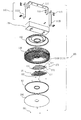
図1は、LED照明装置100の斜視図である。図1(a)は、LED照明装置100の発光面側が見える斜視図であり、図1(b)は、LED照明装置100の上側が見える斜視図である。図2は、LED照明装置100の構成を示す、分解斜視図である。図2に示すように、LED照明装置100は、アーム部110、電源装置120、天面カバー130(本体カバー部)、本体140(装置本体)、LED基板170、反射板181、パッキン183、カバー184を備える。なお、パッキン183はなくてもよい。アーム部110は、上側アーム111、第1サイドアーム112A、第2サイドアーム112Bが互いにボルト113、ナット114で結合される。また、LED基板170、反射板181は、ネジ182で本体140に取り付けられる。なお、LED基板170がネジ182で取り付けられる後述の円形ベース部1430のベース下面1431は、基板取付部である。
FIG. 1 is a perspective view of the
(放熱経路)
図2を参照して放熱経路を説明する。LED基板170のLED素子174の発熱に伴う熱は、例えば、LED基板170から本体140(円形ベース部1430)に伝導し、放熱フィン1441〜1443(図5等で後述)、及び天面カバー130から大気に放熱される。
(Heat dissipation path)
The heat dissipation path will be described with reference to FIG. The heat accompanying the heat generation of the
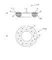
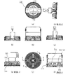
図3は、LED照明装置100の上面図等及び断面図である。図3の(a)〜(h)において、(a)は上面図、(b)は正面図、(c)は底面図、(d)は左側面図、(e)は右側面図である。(f)は断面A−A、(g)は断面C−C、(h)は断面D−Dである。図4は、本体140の上面図等及び断面図である。(a)は上面図、(b)は正面図、(c)は底面図、(d)は右側面図である。(e)は断面B−B、(f)は断面C−Cである。図5は、天面カバー130と本体140との組み付けを示す斜視図である。
FIG. 3 is a top view and a cross-sectional view of the
図1〜図5を参照して、LED照明装置100を具体的に説明する。LED照明装置100は、図1(a)に示すように光源として複数のLED(半導体発光素子)を用いる。複数のLEDは、LED基板170(図2)に実装される。以降、LED基板170のうちLEDが実装される面を実装面171といい、実装面171の反対側の面を基板裏面172という。図2に示すように、本体140には、LED基板170が取り付けられる。本体140は、LED基板170の基板裏面172と対向してLED基板170が取り付けられる基板取付部となる後述の円形ベース部1430を有する。また本体140は、円形ベース部1430に取り付けられたLED基板170の実装面171から基板裏面172に向かう方向である延伸方向173に延び、LED基板170から熱を吸熱して伝熱する複数の放熱フィン1441(放熱部、図5で後述)を有する。また、図5に示すように、第2中空円筒部1420の外側表面に、その外周に沿って複数の放熱フィン1442を有する。また第1中空円筒部1410の内側表面に、その内周に沿って、複数の放熱フィン1443を有する。このうち主要なフィンは、放熱フィン1441である。
The
(天面カバー130と本体140との組み付け)
図3(a)、(b)、(d)、(e)、図5に示すように、放熱フィン1441に着目すると、天面カバー130は、複数の放熱フィン1441を延伸方向173と反対方向から見下ろした場合に複数の放熱フィン1441を覆うように本体140に配置される。また、天面カバー130は、外形が延伸方向173に凸となる凸形状(あるいは山形状)である。ここで凸形状の意味は、図3(b)、(d)、(e)に示すように、天面カバー130が側面図あるいは正面図でみたときに、山形状(あるいは台形形状)に見えることを意味する。すなわち天面カバー130を山形状(あるいは台形形状)にして斜面を形成することで、放熱フィン1441の間への埃の堆積を防止すると共に、天面カバー130自身への埃堆積を低減する。
(Assembly of
As shown in FIGS. 3A, 3 </ b> B, 3 </ b> D, 5 </ b> E, and 5, when attention is paid to the
さらに、天面カバー130と本体140との組み付けを詳しく説明する。図5に示すように、本体140は、円形ベース部1430、第1中空円筒部1410、第2中空円筒部1420、複数の放熱フィン1441を備える。円形ベース部1430は、略円盤形状であって、一方の面であるベース下面1431(基板取付部、図4(c)、(f))に、LED基板170が取り付けられる。第1中空円筒部1410は、円形ベース部1430のベース下面1431の反対側の面であるベース上面1432(図4(f))に円形ベース部1430と略同心(図4(a))に配置され、円形ベース部1430のベース上面1432から延伸方向173に起立(図4(f))する所定の内径を有する略円筒形状であり、かつ板状体である。第2中空円筒部1420は、円形ベース部1430のベース上面1432(図4(f))に円形ベース部1430と略同心(図4(a))に配置され、円形ベース部1430のベース上面1432から延伸方向173に起立(図4(f))すると共に、第1中空円筒部1410の内径よりも大きい内径と、円形ベース部1430の外径よりも小さい外径とを有する略円筒形状であり、かつ、板状体である。
Further, the assembly of the
複数の放熱フィン1441(複数の放熱部)のそれぞれは、図5に示すように第1中空円筒部1410の外側と第2中空円筒部1420の内側との間において円形ベース部1430の半径方向に放射状に配置される。複数の放熱フィン1441のそれぞれは、板厚の面である一方の板厚側面1441−1が第1中空円筒部1410の外側表面1411に接続し、他方の板厚側面1441−2が第2中空円筒部1420の内側表面1421に接続する。そして、それぞれの放熱フィン1441は、図5、図3(g)(f)等に示すように、外側表面1411の付近及び内側表面1421の付近よりも、外側表面1411と内側表面1421との中間付近のほうが、延伸方向173(図5)の高かさが高い延伸方向に凸の凸形状1441−3(図3(g)(f))である。図5に示すように、第1中空円筒部1410は板厚側面1441−1と略同じ高さである。同様に、第2中空円筒部1420は、板厚側面1441−2と略同じ高さである。図3(a)に示すように、天面カバー130は、延伸方向173と反対方向から見下ろした場合に略円形状であり、外縁133が第2中空円筒部1420の外径に略一致する(図5)。また本体カバー部の凸形状は、複数の放熱フィン1441の凸形状1441−3に適合する形状である。図5で説明すれば、放熱フィン1441の凸形状1441−3の先端は、天面カバー130の裏面に当接する(図3(f)、(g))。この当接によって放熱フィン1441から天面カバー130に熱が伝導する。
Each of the plurality of radiating fins 1441 (the plurality of radiating portions) is arranged in the radial direction of the
なお、LED照明装置100では本体140には、図5に示すように本体側風穴1450(図4(a)(c))が形成されておいる。したがって本体140は、中央部分に穴のあいたドーナツ形状である(図4(a),(c),(e),図5等)。天面カバー130にも、本体140に取り付けられた際に本体側風穴1450と連通するカバー側風穴132(図5)が形成されている。従って、本体側風穴1450、カバー側風穴132を通過する空気によって放熱性が向上する。
In the
(下降形状)
円形ベース部1430は、第2中空円筒部1420の外径よりも外側の外周領域1433(図4(f)、図5)が、外側方向に向かうにしたがって、延伸方向173と反対の方向に下降する下降形状1434(図4(f))である。つまり、第2中空円筒部1420の円形ベース部1430からの起立部の外側周囲を囲む外周領域1433は、延伸方向173と反対の方向に下降する斜面形状である。この斜面形状によって外周領域1433における埃の体積を低減することができる。
(Descent shape)
In the
以上に説明した実施の形態1のLED照明装置100は以下の効果を有する。
(1)天面カバー130で複数の放熱フィン1441を覆うので、複数の放熱フィン1441の間に埃が堆積することを低減できる。
(2)また、複数の放熱フィン1442が形成される外周領域1433を下降形状1434(斜面形状)としたので放熱フィン1442間に埃が堆積することを低減できる。
(3)また、複数の放熱フィン1441の先端と天面カバー130の内側とが当接するようにしたので、複数の放熱フィン1441の熱を天面カバー130からも放熱することができる。
The
(1) Since the plurality of
(2) Further, since the outer
(3) Since the tips of the plurality of
実施の形態2.
次に図6〜図23を参照して実施の形態2を説明する。図6〜図18では実施の形態2の概念を説明し、図19〜図23でその概念を用いた具体的なLED照明装置200を説明する。実施の形態2の特徴は、実施の形態1における天面カバー130と本体140とを一体成形(例えばアルミダイキャスト)し、放熱フィン1411のLED基板170側の先端を、LED基板170の基板裏面172に当接(熱的に接続)した構成である。実施の形態2では実施の形態1の放熱フィン1411に相当する要素は棒状でもよいし、平板状や中空円筒状や中空円筒の一部分(上方からみて360度を中空円筒とした場合、360度未満)の形状でもよいので、放熱フィン1411に相当する要素を放熱部とも呼ぶ。
Next, the second embodiment will be described with reference to FIGS. 6 to 18 explain the concept of the second embodiment, and FIGS. 19 to 23 explain a specific
(LED照明装置201A)
図6は、実施の形態2のLED照明装置201Aの斜視図である。
(1)LED照明装置201Aは、LED基板30と、本体カバー部20Aとを備えている。本体カバー部20Aの一部が天面カバー130に相当する一体成形カバー29である。
(2)LED基板30は、複数のLED素子31が実装されるLED実装面33とLED実装面33の反対側の面である基板裏面34とを有する。図6では基板裏面34の破線は、LED素子31を示している。
図7は図6のA矢視でありLED実装面33のLED素子31(4個)を示している。
(3)本体カバー部20Aは、本体を兼ねている。つまり本体カバー部20Aは、実施の形態1の天面カバー130と本体140とを兼ねている。本体カバー部20では、LED基板30を取り付ける基板取付部は省略している。
(4)本体カバー部20Aは、一体成形を想定している。一体成形によって放熱部と一体成形カバー29との接続部28(図10)が確実に同一部材で一体につながるので、第1の棒状リブ21A等がLED基板30から吸熱した熱を確実に高い効率で一体成形カバー29に伝導できる。
(5)本体を兼ねる本体カバー部20Aは、LED基板30が基板裏面34側から取り付けられる基板取付部(図示は省略した)と、取り付けられたLED基板30のLED実装面33から基板裏面34に向かう延伸方向173に延び、LED基板30から熱を吸熱して伝熱かつ放熱する「後述の第1の棒状リブ21A、第2の棒状リブ22A」とを有する。複数の放熱部の構成は、例えば、LED基板30に実装される複数のLED素子31の配置に応じて決定される。
(6)本体カバー部20Aは、複数の放熱部を備えるが、図6では、棒状の放熱部として第1の棒状リブ21Aと第2の棒状リブ22Aを示した。なお放熱部をリブと呼ぶのは放熱部の機能と共に強度部材としての機能も有するからである。放熱部に強度部材の機能も持たせることで、本体カバー部20Aの重量を低減できる。図示の見易さのため2本としているが、棒状の放熱部は例えば合計4本であり、残りの2本もそれぞれ基板裏面34のLED素子31の裏側に対応する箇所にその先端が当接する。第1の棒状リブ21A等は、基板裏面34に面する側の一体成形カバー29の裏面から起立し、その先端が基板裏面34に接続して、LED基板30から熱を吸収する。
(7)図6に示したように、第1の棒状リブ21A、第2の棒状リブ22A等は、先端の少なくとも一部の領域(図6では全部の領域)が、LED実装面33に実装されたLED素子31の実装位置の略反対側の基板裏面34の位置に接続する。基板裏面34のうちでもLED素子31のちょうど裏側にあたる範囲が温度の高い領域である。よって放熱部である第2の棒状リブ22Aの先端をこの領域に接続することで、LED基板30から効率よく吸熱できる。
(8)また、図7(b)のA’矢視のように、本体カバー部20Aの一体成形カバー29は、第1の棒状リブ21A、第2の棒状リブ22A等を延伸方向173と反対方向(A’矢視)から見下ろした場合に、第1の棒状リブ21A、第2の棒状リブ22A等を覆うように配置される。また図6に示すように、外形が延伸方向173に凸となる凸形状(山形状、あるいはかさ形状)である。この一体成形カバー29の形状によって、放熱部である第1の棒状リブ21A、第2の棒状リブ22A等の間における埃の堆積を低減できる。
(
FIG. 6 is a perspective view of the
(1) The
(2) The
FIG. 7 is an arrow A view of FIG. 6 and shows the LED elements 31 (four) on the
(3) The main
(4) The main
(5) The main
(6) The main
(7) As shown in FIG. 6, the first rod-shaped rib 21 </ b> A, the second rod-shaped rib 22 </ b> A, etc. are mounted on the
(8) Also, as shown by the arrow A ′ in FIG. 7B, the integrally formed
(LED照明装置201B)
図8は、実施の形態2のLED照明装置201Bの斜視図である。
(1)LED照明装置201Bは、LED照明装置201Aに対して、LED基板30におけるLED素子31の配置が異なり、これに対応して放熱部が板状である。つまり本体カバー部20Bは、放熱部として第1の板状リブ21Bと第2の板状リブ22Bを有する。
(2)図8にしたように、第1の板状リブ21B、第2の板状リブ22B等は、先端の少なくとも一部の領域(図8では一部の領域)が、LED実装面33に実装されたLED素子31の実装位置の略反対側の基板裏面34の位置に接続する。
(3)LED照明装置201Bの構成の場合も、LED照明装置201Aと同様の効果を得ることができる。
(
FIG. 8 is a perspective view of the
(1) The
(2) As shown in FIG. 8, the first plate-like rib 21 </ b> B, the second plate-like rib 22 </ b> B, and the like have at least a partial region (partial region in FIG. 8) at the tip, and the
(3) In the case of the configuration of the
(LED照明装置201C)図9は、実施の形態2のLED照明装置201Cの斜視図である。
(1)LED照明装置201Cは、LED照明装置201Aに対して、LED基板30におけるLED素子31の配置が異なる。LED素子31の配置は、円周状の配置である。これに対応して放熱部が中空円筒板状である。つまり本体カバー部20Cは、放熱部として中空円筒状リブ21Cを有する。
(2)図9にしたように、中空円筒状リブ22Cは、先端の少なくとも一部の領域(図9では一部の領域)が、LED実装面33に実装されたLED素子31の実装位置の略反対側の基板裏面34の位置に接続する。
(3)LED照明装置201Cの構成の場合も、LED照明装置201Aと同様の効果を得ることができる。
(LED Lighting Device 201C) FIG. 9 is a perspective view of the LED lighting device 201C of the second embodiment.
(1) The LED illumination device 201 </ b> C differs from the LED illumination device 201 </ b> A in the arrangement of the
(2) As shown in FIG. 9, the hollow cylindrical rib 22 </ b> C has at least a part of the tip (part of the part in FIG. 9) of the mounting position of the
(3) In the case of the configuration of the LED lighting device 201C, the same effect as that of the
図10に、本体カバー部20A、20B、20Cの断面F−F、断面G−G、断面H−Hを示した。なお、本体カバー部20A等は、図11、図12に示すように、一体成形カバー29のおもて面に、LED基板30の基板裏面34に接続する複数の放熱部とは異なる別の複数の第2の放熱部(外側放熱フィン24)が一体成形によって形成されてもよい。外側放熱フィン24を形成することで、さらに放熱性が向上する。
FIG. 10 shows a cross section FF, a cross section GG, and a cross section HH of the main
(LED照明装置201D)
次に図13〜図18を参照してLED照明装置201Dを説明する。LED照明装置201Dは図15(a)に示すように、LED基板30と本体カバー部20Dを備えている。本体カバー部20Dは本体カバー部20A等と同様に、本体の機能を兼用する。
(
Next, the
LED照明装置201Dの特徴は、本体カバー部20Dがドーナツ形状である点である。図13は、本体カバー部20Dの形状を説明する図である。(a)は略富士山型の凸形断面25(後述の櫛形状)を示す。富士山型の頂上側25−1を下にした形状である。(b)は回転体の断面を示す。(c)はC矢視を示す。また、図14は、D矢視を示す。
The feature of the
本体カバー部20D(本体と一体成形である)は、その外形が図13(a)に示すように、略富士山型の凸形断面25を回転軸26から横方向に移動させた位置に配置して回転軸26まわりに1回転してできるドーナツ形状の回転体形状をなす。本体カバー部20Dは、凸形断面25の回転方向に連続する少なくとも一部の領域の断面が、略富士山型の凸形断面25のうち斜面と頂上の形状を維持しつつ内部の一部が削除されて略富士山型の凸形断面25の底辺側25−2に向かう複数の歯25−3を有する櫛形状の断面である。そして、複数の放熱部のそれぞれは、略富士山型の櫛形状の断面における櫛のそれぞれの歯25−3の部分が回転軸まわりに回転してできるそれぞれの中空円筒の少なくとも一部分である。本体カバー部20Dにおける放熱部は、図13(c)に示す中空円筒状リブ21D−1,21D−2であり、この例では全部が中空円筒形状である。また、頂上側25−1の回転形状によって実施の形態1の天面カバー130に相当する一体成形カバー29が形成される。
As shown in FIG. 13A, the main
図15は、LED照明装置201Dの構成を示す図である。(a)は縦断面であり、(b)はE矢視である。(b)に示すように、LED素子31は同心円状に配置されおり、このLED素子31配置に対応して、中空円筒状リブ21D−1,21D−2は中空円筒形状となっている。つまり(a)に示すように、中空円筒状リブ21D−1,21D−2の先端(歯25−3の先端に相当)が、LED実装面33に実装されたLED素子31の実装位置の略反対側の基板裏面34の位置(破線の円周上)に接続する。また(a),(b)に示すように、LED基板30のドーナツの穴に相当する部分にも穴が開いており、LED照明装置201DはE方向、反E方向に空気が通過し、放熱性の向上を図っている。
FIG. 15 is a diagram illustrating a configuration of the
図16は、図15(b)に相当する図(E矢視)であり、LED素子31の配置が異なる場合である。図16では、LED素子31は円周上に配置されるが、部分的に密集して配置される。よって、この部分的配置に対応して、中空円筒状リブ21D−1,21D−2は、その中空円筒の一部分とした構成である。図17は、図13(c)に対応する図である。また図18(a)〜(c)は、それぞれ図17の断面X―X、Y―Y、Z―Zを示す。図18(a)〜(c)の破線は、櫛形状の凸形断面25において欠けている歯25−3を示している。図17の放熱部27Aは、図16の3つのLED素子31であるLED素子群27Bに対応している。つまり放熱部27Aの先端は、LED素子群27Bの実装位置の略反対側の基板裏面34の位置に接続する。
FIG. 16 is a view corresponding to FIG. 15B (see arrow E), and shows a case where the arrangement of the
以上に説明したLED照明装置201Dは、放熱部の形状が、図9のLED照明装置201Cと同様な中空円筒形状であるが、LED照明装置201DもLED照明装置201A等と同様の効果を有する。
The
(LED照明装置200)
次に、実施の形態2のLED照明装置200を説明する。LED照明装置200は、上記の実施の形態2で述べた概念を具体的なLED照明装置としたものである。LED照明装置200は、図13〜図18で述べたLED照明装置201Dの具体化である。従ってLED照明装置200はLED照明装置201Dと同じ効果を持つ。
(LED lighting device 200)
Next, the
以下に図19〜図23を参照してLED照明装置200を説明する。図19〜図23は実施の形態1の図1〜図5に対応する。上記のようにLED照明装置200はLED照明装置201の具体化であり、LED照明装置200の特徴は、本体140と天面カバー130とが一体成形されると共に、櫛形状の歯25−3の先端がLED基板の基板裏面に接続することにある。
The
(1)図19は、LED照明装置200の斜視図である。図19(a)は、LED照明装置200の発光面側が見える斜視図であり、図19(b)は、LED照明装置200の上側が見える斜視図である。
(2)図20は、LED照明装置200の構成を示す、分解斜視図である。図20に示すように、LED照明装置200は、アーム部210、電源装置220、本体240(本体カバー部を兼ねる)、LED基板270、反射板281、パッキン283、カバー284を備える。なお、パッキン283はなくてもよい。実施の形態1のLED照明装置100に対して天面カバー130と本体140とが一体成形されて本体240となった他は、LED照明装置200LED照明装置100と同様の構成である。図20に示すようにLED基板270は、実施の形態1のLED照明装置100の円形ベース部1430のベース下面1431に相当する箇所に取り付けられるが、この部分が基板取付部である。この基板取付部は、図22(f)に示す断面C−Cのネジ穴247である。
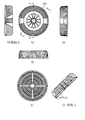
(3)図21は、LED照明装置200の上面図等及び断面図である。図21の(a)〜(h)において、(a)は上面図、(b)は正面図、(c)は底面図、(d)は左側面図、(e)は右側面図である。(f)は断面A−A、(g)は断面C−C、(h)は断面D−Dである。
(4)図22は、本体240の上面図等及び断面図である。(a)は上面図、(b)は正面図、(c)は底面図、(d)は右側面図である。(e)は断面B−B、(f)は断面C−Cである。
(5)図23は、本体240の斜視図である。
(1) FIG. 19 is a perspective view of the
(2) FIG. 20 is an exploded perspective view showing the configuration of the
(3) FIG. 21 is a top view of the
(4) FIG. 22 is a top view and a sectional view of the
(5) FIG. 23 is a perspective view of the
(本体240)
以下、LED照明装置200の特徴は本体240にあるので、LED照明装置201D(図15)との対比で本体240を説明する。本体240は本体カバー部を兼ねる。図23に本体カバー部241の斜視図を示した。また、図21(f)の破線で囲む部分が、本体カバー部241の断面である。この断面を図13(a)の回転軸26まわりに回転することで、天面カバー130の形状の一体成形カバーが形成される。図23に示すように、本体カバー部241の表面には、外側表面に外側放熱フィン244が形成され、内側表面(内径側表面)に内側放熱フィン245が形成されている。本体カバー部241の断面が図13で述べた凸形断面25である。図21(f)に示す略富士山型の凸形断面242は、図13(a)の凸形断面25に対応する。本体カバー部241側が頂上側243である。なお、図21(f)の断面A−Aは櫛形状ではない。櫛形状の断面は図21(g)、図22(f)に現れている。図21(g)を参照して説明する。図21(g)の断面C−Cは、富士山型の凸形断面242とはなっていないが、これは外側放熱フィン244、内側放熱フィン245が形成されている断面のためである。本体240の特徴は本体とカバーとの一体化及び内部の断面形状にあり、外側放熱フィン244、内側放熱フィン245は必須の構成要素ではない。したがって外側放熱フィン244、内側放熱フィン245がない場合は、断面C−Cには富士山型の凸形断面242が現れる。図21(g)の断面C−Cは、内部の一部が削除されて底辺に向かう複数の歯246を有する櫛形状の断面をなしている。図13で述べたが、複数の放熱部のそれぞれは、櫛形状の断面における櫛のそれぞれの歯の部分が回転軸26まわりに回転してできるそれぞれの中空円筒の少なくとも一部分である。つまり、図13(c)の場合は1周全部が一つの中空円筒状の放熱部であったが、本体240では、図22(c)に示すように、1周が4分割された形状である。その分割の区分け部になる断面が図21(c)の断面A−Aのように、櫛形状の出現しない断面である。なお、本体240はドーナツ形状であるので、中央の穴を図23の矢印Kの方向(あるいはその反対方向)に空気が通過できるので、放熱効果に優れている。
(Main body 240)
Hereinafter, since the feature of the
つまり放熱部27Aの先端は、LED素子群27Bの実装位置の略反対側の基板裏面34の位置に接続する。
That is, the tip of the
以上の実施の形態2のLED照明装置201A〜201D、200は、本体背面の外郭(本体カバー部)を凸形状(山形状)とし、その表面に放熱フィンを有することで、放熱性能を確保しつつ、ほこりの堆積を軽減できる。また実施の形態2のLED照明装置201A等では、本体カバー部の裏面から起立する放熱部を形成し、放熱部の先端をLED素子の実装位置の略反対側の基板裏面の位置に接続する。また放熱部は強度部材の機能も有する。よって、軽量化を図りながらLEDモジュールの熱を器具外郭に伝熱し、放熱できる。また、本体とカバーとをADC(アルミダイキャスト)による一体成形とすることで、部品点数の削減が図れる。
The
100 LED照明装置、110 アーム部、111 上側アーム、112A 第1サイドアーム、112B 第2サイドアーム、113 ボルト、114 ナット、120 電源装置、130 天面カバー、131 斜面、132 カバー側風穴、133 外縁、140 本体、1410 第1中空円筒部、1420 第2中空円筒部、1430 円形ベース部、1431 ベース下面、1432 ベース上面、1433 外周領域、1434 下降形状、1441 放熱フィン、1441−1 板厚側面、1441−2 板厚側面、1441−3 凸形状、1442 放熱フィン、1443 放熱フィン、1450 本体側風穴、170 LED基板、171 実装面、172 基板裏面、173 延伸方向、174 LED素子、181 反射板、182 ネジ、183 パッキン、184 カバー、185 ネジ、20A 本体カバー部、20A−1 本体カバー部、21A 第1の棒状リブ、22A 第2の棒状リブ、23 カバー側風穴、24 外側放熱フィン、20B 本体カバー部、21B 第1の板状リブ、22B 第2の板状リブ、20C 本体カバー部、21C 中空円筒状リブ、20D 本体カバー部、21D 櫛形断面、21D−1 中空円筒状リブ、21D−2 中空円筒状リブ、24 放熱フィン、25 凸形断面、25−1 頂上側、25−2 底辺側、25−3 歯、26 回転軸、27A 放熱部、27B LED素子群、28 接続部、29 一体成形カバー、200 LED照明装置、210 アーム部、211 上側アーム、212A 第1サイドアーム、212B 第2サイドアーム、213 ボルト、214 ナット、220 電源装置、240 本体、241 本体カバー部、242 凸形断面、243 頂上側、244 外側放熱フィン、245 内側放熱フィン、246 歯、247 ネジ穴、270 LED基板、281 反射板、282 ネジ、283 パッキン、284 カバー、285 ネジ、30 LED基板、31 LED素子、32 基板風穴、33 LED実装面、34 基板裏面。 100 LED lighting device, 110 arm portion, 111 upper arm, 112A first side arm, 112B second side arm, 113 bolt, 114 nut, 120 power supply device, 130 top cover, 131 slope, 132 cover side air hole, 133 outer edge , 140 body, 1410 first hollow cylindrical portion, 1420 second hollow cylindrical portion, 1430 circular base portion, 1431 base lower surface, 1432 base upper surface, 1433 outer peripheral region, 1434 descending shape, 1441 heat radiation fin, 1441-1 plate thickness side surface, 1441-2 Thickness side surface, 1441-3 Convex shape, 1442 Radiation fin, 1443 Radiation fin, 1450 Body side air hole, 170 LED substrate, 171 Mounting surface, 172 Substrate back surface, 173 Stretch direction, 174 LED element, 181 Reflector, 182 , 183 packing, 184 cover, 185 screw, 20A body cover part, 20A-1 body cover part, 21A first rod-shaped rib, 22A second rod-shaped rib, 23 cover side air hole, 24 outer radiating fin, 20B body cover section 21B 1st plate-like rib, 22B 2nd plate-like rib, 20C main body cover part, 21C hollow cylindrical rib, 20D main body cover part, 21D comb-shaped cross section, 21D-1 hollow cylindrical rib, 21D-2 hollow cylinder Rib, 24 Radiation fin, 25 Convex cross section, 25-1 Top side, 25-2 Bottom side, 25-3 Teeth, 26 Rotating shaft, 27A Heat radiation part, 27B LED element group, 28 Connection part, 29 Integrated molding cover , 200 LED lighting device, 210 arm portion, 211 upper arm, 212A first side arm, 212B second side arm 213 bolts, 214 nuts, 220 power supply, 240 main body, 241 main body cover, 242 convex cross section, 243 top side, 244 outer radiating fins, 245 inner radiating fins, 246 teeth, 247 screw holes, 270 LED board, 281 Reflector, 282 screw, 283 packing, 284 cover, 285 screw, 30 LED substrate, 31 LED element, 32 substrate air hole, 33 LED mounting surface, 34 substrate back surface.
Claims (9)
前記複数の半導体発光素子が実装される実装面と前記実装面の反対側の面である裏面とを有する基板と、
前記基板が取り付けられる装置本体であって、前記基板の裏面と対向して前記基板が取り付けられる基板取付部と、前記基板取付部に取り付けられた前記基板の実装面から前記裏面に向かう方向である延伸方向に延び、前記基板から熱を吸熱して伝熱する複数の放熱部とを有する装置本体と、
前記複数の放熱部を前記延伸方向と反対方向から見下ろした場合に前記複数の放熱部を覆うように前記装置本体に配置されると共に、外形が前記延伸方向に凸となる凸形状の本体カバー部と
を備え、
前記装置本体と前記本体カバー部とは、
一体成形され、
前記本体カバー部は、
前記一体成形によって薄肉成形され、
前記複数の放熱部のそれぞれは、
前記基板の裏面側に面する側の前記本体カバー部の裏面から起立し、先端が前記基板の裏面に接続して前記基板から熱を吸収し、
一体成形される前記本体カバー部と前記装置本体とは、
その外形が、略富士山型の凸形断面を回転軸から横方向に移動させた位置に配置して前記回転軸まわりに1回転してできるドーナツ形状の回転体形状をなすと共に、前記凸形断面の回転方向に連続する少なくとも一部の領域の断面が、前記略富士山型の凸形断面のうち斜面と頂上の形状を維持しつつ内部の一部が削除されて前記略富士山型の凸形断面の底辺に向かう複数の歯を有する櫛形状の断面をなし、
前記複数の放熱部のそれぞれは、
前記略富士山型の前記櫛形状の断面における櫛のそれぞれの歯の部分が前記回転軸まわりに回転してできるそれぞれの中空円筒の少なくとも一部分であることを特徴とする照明装置。 In an illumination device using a plurality of semiconductor light emitting elements as a light source,
A substrate having a mounting surface on which the plurality of semiconductor light emitting elements are mounted and a back surface opposite to the mounting surface;
An apparatus main body to which the substrate is attached, a substrate attachment portion to which the substrate is attached facing the back surface of the substrate, and a direction from the mounting surface of the substrate attached to the substrate attachment portion toward the back surface An apparatus body having a plurality of heat radiating portions extending in the stretching direction and absorbing heat from the substrate to transfer heat;
A convex body cover portion that is disposed in the apparatus main body so as to cover the plurality of heat dissipation portions when the plurality of heat dissipation portions are looked down from the direction opposite to the extending direction, and whose outer shape is convex in the extending direction. And
The apparatus main body and the main body cover part are:
Integrally molded,
The body cover part is
Thin wall molding by the integral molding,
Each of the plurality of heat dissipation units is
Standing up from the back surface of the body cover part on the side facing the back surface side of the substrate, the tip is connected to the back surface of the substrate and absorbs heat from the substrate,
The body cover part and the apparatus body to be integrally molded are
The outer shape is a donut-shaped rotating body that is formed by rotating a convex section of a substantially Mt. Fuji shape in a lateral direction from the rotational axis and rotating around the rotational axis. The cross section of at least a part of the region continuous in the rotation direction of the substantially Mt. Fuji-type convex cross section, while maintaining the shape of the slope and the top, a part of the inside is deleted, and the substantially Mt. Fuji-type convex cross section A comb-shaped cross section having a plurality of teeth toward the bottom of the
Each of the plurality of heat dissipation units is
The illumination device according to claim 1, wherein each tooth portion of the comb in the substantially Mt. Fuji-shaped cross section is at least a part of each hollow cylinder formed by rotating around the rotation axis.
前記先端の少なくとも一部の領域が、前記基板の実装面に実装された前記半導体発光素子の実装位置の略反対側の前記裏面の位置に接続することを特徴とする請求項1に記載の照明装置。 Each of the plurality of heat dissipation units is
2. The illumination according to claim 1, wherein at least a partial region of the tip is connected to the position of the back surface substantially opposite to the mounting position of the semiconductor light emitting element mounted on the mounting surface of the substrate. apparatus.
前記本体カバー部の裏面の反対側の面である本体カバー部のおもて面に、前記複数の放熱部とは異なる別の複数の第2の放熱部が前記一体成形によって形成されたことを特徴とする請求項1または2のいずれかに記載の照明装置。 The body cover part is
A plurality of second heat radiating portions different from the plurality of heat radiating portions are formed on the front surface of the main body cover portion opposite to the back surface of the main body cover portion by the integral molding. The illuminating device according to claim 1, wherein the illuminating device is characterized in that
前記複数の半導体発光素子が実装される実装面と前記実装面の反対側の面である裏面とを有する基板と、
前記基板が取り付けられる装置本体であって、前記基板の裏面と対向して前記基板が取り付けられる基板取付部と、前記基板取付部に取り付けられた前記基板の実装面から前記裏面に向かう方向である延伸方向に延び、前記基板から熱を吸熱して伝熱する複数の放熱部とを有する装置本体と、
前記複数の放熱部を前記延伸方向と反対方向から見下ろした場合に前記複数の放熱部を覆うように前記装置本体に配置されると共に、外形が前記延伸方向に凸となる凸形状の本体カバー部と
を備え、
前記装置本体は、
略円盤形状であって、一方の面である下面に前記基板が取り付けられる円形ベース部と、
前記円形ベース部の前記下面の反対側の面である上面に前記円形ベース部と略同心に配置され、前記円形ベース部の前記上面から前記延伸方向に起立する所定の内径を有する略円筒形状である板状体の第1中空円筒部と、
前記円形ベース部の上面に前記円形ベース部と略同心に配置され、前記円形ベース部の前記上面から前記延伸方向に起立すると共に、前記第1中空円筒部の外径よりも大きい内径と、前記円形ベース部の外径よりも小さい外径とを有する略円筒形状である板状体の第2中空円筒部と
を備え、
前記複数の放熱部のそれぞれは、
板状の放熱フィンであって、
前記第1中空円筒部の外側と前記第2中空円筒部の内側との間において前記円形ベース部の半径方向に放射状に配置され、板厚の面である一方の板厚側面が前記第1中空円筒部の外側表面に接続し他方の板厚側面が前記第2中空円筒部の内側表面に接続し、前記第1中空円筒部の前記外側表面の付近及び前記第2中空円筒部の前記内側表面の付近よりも前記第1中空円筒部の前記外側表面と前記第2中空円筒部の前記内側表面との中間付近のほうが、前記延伸方向の高かさが高い前記延伸方向に凸の凸形状であり、
前記第1中空円筒部は、
前記一方の板厚側面と略同じ高さであると共に、
前記第2中空円筒部は、
前記他方の板厚側面と略同じ高さであり、
前記本体カバー部は、
前記延伸方向と反対方向から見下ろした場合に略円形状であり、外縁が前記第2中空円筒部の外径に略一致すると共に前記本体カバー部の前記凸形状が複数の前記放熱フィンの前記凸形状に適合する形状であることを特徴とする照明装置。 In an illumination device using a plurality of semiconductor light emitting elements as a light source,
A substrate having a mounting surface on which the plurality of semiconductor light emitting elements are mounted and a back surface opposite to the mounting surface;
An apparatus main body to which the substrate is attached, a substrate attachment portion to which the substrate is attached facing the back surface of the substrate, and a direction from the mounting surface of the substrate attached to the substrate attachment portion toward the back surface An apparatus body having a plurality of heat radiating portions extending in the stretching direction and absorbing heat from the substrate to transfer heat;
A convex body cover portion that is disposed in the apparatus main body so as to cover the plurality of heat dissipation portions when the plurality of heat dissipation portions are looked down from the direction opposite to the extending direction, and whose outer shape is convex in the extending direction. And
The apparatus main body is
A circular base portion having a substantially disk shape, wherein the substrate is attached to a lower surface which is one surface;
The upper surface of the circular base portion opposite to the lower surface is disposed substantially concentrically with the circular base portion, and has a substantially cylindrical shape having a predetermined inner diameter standing in the extending direction from the upper surface of the circular base portion. A first hollow cylindrical portion of a plate-like body;
The upper surface of the circular base portion is disposed substantially concentrically with the circular base portion, stands up in the extending direction from the upper surface of the circular base portion, and has an inner diameter larger than the outer diameter of the first hollow cylindrical portion, A plate-like second hollow cylindrical portion having a substantially cylindrical shape having an outer diameter smaller than the outer diameter of the circular base portion,
Each of the plurality of heat dissipation units is
A plate-like heat dissipating fin,
Between the outer side of the first hollow cylindrical part and the inner side of the second hollow cylindrical part, the circular base part is radially arranged in the radial direction, and one plate thickness side surface which is a plate thickness surface is the first hollow side. Connected to the outer surface of the cylindrical portion and the other thickness side surface is connected to the inner surface of the second hollow cylindrical portion, near the outer surface of the first hollow cylindrical portion and the inner surface of the second hollow cylindrical portion The height near the middle of the outer surface of the first hollow cylindrical portion and the inner surface of the second hollow cylindrical portion is higher in the stretching direction than in the vicinity of ,
The first hollow cylindrical portion is
The height is substantially the same as the one plate thickness side,
The second hollow cylindrical portion is
It is approximately the same height as the other plate thickness side surface,
The body cover part is
When viewed from the direction opposite to the extending direction, the shape is substantially circular, the outer edge substantially matches the outer diameter of the second hollow cylindrical portion, and the convex shape of the main body cover portion is the convexity of the plurality of radiating fins. An illumination device characterized by having a shape that conforms to the shape.
前記第2中空円筒部の外径よりも外側の外周領域が、外側方向に向かうにしたがって、前記延伸方向と反対の方向に下降する下降形状であることを特徴とする請求項4に記載の照明装置。 The circular base portion is
5. The illumination according to claim 4, wherein an outer peripheral region outside the outer diameter of the second hollow cylindrical portion has a descending shape that descends in a direction opposite to the extending direction as it goes outward. apparatus.
前記基板が取り付けられた状態で前記延伸方向に貫通して空気を通過させる風穴が形成され、
前記本体カバー部は、
前記装置本体の風穴と連通するカバー側風穴が形成されたことを特徴とする請求項1から5のいずれか一項に記載の照明装置。 The apparatus main body is
An air hole is formed that allows air to pass through in the stretching direction with the substrate attached,
The body cover part is
The illumination device according to any one of claims 1 to 5, wherein a cover-side air hole communicating with the air hole of the device body is formed.
前記複数の半導体発光素子が実装される実装面と前記実装面の反対側の面である裏面とを有する基板と、
前記基板が取り付けられる装置本体であって、前記基板の裏面と対向して前記基板が取り付けられる基板取付部と、前記基板取付部に取り付けられた前記基板の実装面から前記裏面に向かう方向である延伸方向に延び、前記基板から熱を吸熱して伝熱する複数の放熱部とを有する装置本体と、
前記複数の放熱部を前記延伸方向と反対方向から見下ろした場合に前記複数の放熱部を覆うように前記装置本体に配置されると共に、外形が前記延伸方向に凸となる凸形状の本体カバー部であり、前記基板からの熱を吸熱して大気に放熱し、かつ、埃の堆積を防止する斜面が形成されている本体カバー部と
を備えたことを特徴とする照明装置。 In an illumination device using a plurality of semiconductor light emitting elements as a light source,
A substrate having a mounting surface on which the plurality of semiconductor light emitting elements are mounted and a back surface opposite to the mounting surface;
An apparatus main body to which the substrate is attached, a substrate attachment portion to which the substrate is attached facing the back surface of the substrate, and a direction from the mounting surface of the substrate attached to the substrate attachment portion toward the back surface An apparatus body having a plurality of heat radiating portions extending in the stretching direction and absorbing heat from the substrate to transfer heat;
A convex body cover portion that is disposed in the apparatus main body so as to cover the plurality of heat dissipation portions when the plurality of heat dissipation portions are looked down from the direction opposite to the extending direction, and whose outer shape is convex in the extending direction. And a main body cover portion formed with a slope that absorbs heat from the substrate to dissipate heat to the atmosphere and prevents dust accumulation.
環状をなす請求項7に記載の照明装置。 The slope of the body cover part is
The lighting device according to claim 7, which forms an annular shape.
環状をなす第1の斜面と、前記第1の斜面の環状の内側に位置し、前記第1の斜面の環状よりも小さい環状の第2の斜面とを有し、
前記照明装置は、
前記第2の斜面の下方に貫通穴を有する請求項7または請求項8に記載の照明装置。 The body cover portion is the slope,
A first slope having an annular shape, and an annular second slope located inside the annular shape of the first slope and smaller than the annular shape of the first slope,
The lighting device includes:
The lighting device according to claim 7 or 8, wherein a through hole is provided below the second slope.
Priority Applications (1)
| Application Number | Priority Date | Filing Date | Title |
|---|---|---|---|
| JP2012045544A JP5939838B2 (en) | 2012-03-01 | 2012-03-01 | Lighting device |
Applications Claiming Priority (1)
| Application Number | Priority Date | Filing Date | Title |
|---|---|---|---|
| JP2012045544A JP5939838B2 (en) | 2012-03-01 | 2012-03-01 | Lighting device |
Publications (3)
| Publication Number | Publication Date |
|---|---|
| JP2013182777A JP2013182777A (en) | 2013-09-12 |
| JP2013182777A5 JP2013182777A5 (en) | 2015-04-09 |
| JP5939838B2 true JP5939838B2 (en) | 2016-06-22 |
Family
ID=49273304
Family Applications (1)
| Application Number | Title | Priority Date | Filing Date |
|---|---|---|---|
| JP2012045544A Expired - Fee Related JP5939838B2 (en) | 2012-03-01 | 2012-03-01 | Lighting device |
Country Status (1)
| Country | Link |
|---|---|
| JP (1) | JP5939838B2 (en) |
Families Citing this family (20)
| Publication number | Priority date | Publication date | Assignee | Title |
|---|---|---|---|---|
| WO2015087626A1 (en) * | 2013-12-11 | 2015-06-18 | Necライティング株式会社 | Lighting equipment |
| JP2015125871A (en) * | 2013-12-26 | 2015-07-06 | コイト電工株式会社 | Lighting device |
| KR101451397B1 (en) * | 2014-05-28 | 2014-10-22 | (주)쏘모라이팅 | Led lamp with ultralight radiating structure |
| JP6544615B2 (en) * | 2014-08-19 | 2019-07-17 | 株式会社ホタルクス | Heat sink for lighting equipment and lighting equipment |
| KR101468849B1 (en) * | 2014-09-26 | 2014-12-11 | 에이펙스인텍 주식회사 | LED a lights mounted dual radiant heat structure |
| KR101502282B1 (en) * | 2014-09-26 | 2015-03-13 | 에이펙스인텍 주식회사 | a honeycomb structure double heat dissipation LED lighting |
| KR101508326B1 (en) * | 2014-10-23 | 2015-04-07 | 주식회사 청남아이티 | Heat sink assembly for LED lighting |
| KR101708677B1 (en) * | 2014-10-27 | 2017-02-21 | 엘지전자 주식회사 | Lighting device |
| EP3015757B1 (en) | 2014-10-27 | 2017-10-11 | LG Electronics Inc. | Lighting device |
| KR101661988B1 (en) * | 2014-10-27 | 2016-10-04 | 엘지전자 주식회사 | Lighting device |
| KR101661990B1 (en) | 2014-10-27 | 2016-10-04 | 엘지전자 주식회사 | Lighting device |
| KR101661983B1 (en) * | 2014-10-28 | 2016-10-04 | 엘지전자 주식회사 | Lighting device |
| JP6640466B2 (en) * | 2015-04-20 | 2020-02-05 | アイリスオーヤマ株式会社 | LED lighting device |
| JP6260644B2 (en) * | 2016-05-26 | 2018-01-17 | 三菱電機株式会社 | Lighting device |
| JP6716490B2 (en) * | 2017-01-20 | 2020-07-01 | サムジン エルエヌディー カンパニー リミテッドSamjin Lnd Co., Ltd | LED lighting fixture having natural convection type heat dissipation structure |
| KR101931642B1 (en) | 2017-10-24 | 2018-12-21 | 주식회사 삼진엘앤디 | LED Lighting Apparatus Having Heat Dissipation Structure of Natural Convection Type |
| KR102054750B1 (en) * | 2018-05-08 | 2019-12-11 | 주식회사 삼진엘앤디 | LED Lighting Apparatus |
| JP7186535B2 (en) * | 2018-05-29 | 2022-12-09 | 三菱電機株式会社 | Heat sinks, light source units and lighting fixtures |
| JP7382734B2 (en) * | 2019-05-08 | 2023-11-17 | 三菱電機株式会社 | lighting equipment |
| KR102094420B1 (en) * | 2019-10-16 | 2020-03-27 | (주)에이비엠 | Floodlight with heat dissipation module using convection |
Family Cites Families (3)
| Publication number | Priority date | Publication date | Assignee | Title |
|---|---|---|---|---|
| JPH09293411A (en) * | 1996-04-30 | 1997-11-11 | Matsushita Electric Works Ltd | Built-in lighting equipment for heat insulating |
| JPH11186762A (en) * | 1997-12-19 | 1999-07-09 | Fujikura Ltd | Cover for heat sink |
| JP4945433B2 (en) * | 2007-12-28 | 2012-06-06 | シャープ株式会社 | Lighting device |
-
2012
- 2012-03-01 JP JP2012045544A patent/JP5939838B2/en not_active Expired - Fee Related
Also Published As
| Publication number | Publication date |
|---|---|
| JP2013182777A (en) | 2013-09-12 |
Similar Documents
| Publication | Publication Date | Title |
|---|---|---|
| JP5939838B2 (en) | Lighting device | |
| US7712909B2 (en) | Rotating lamp | |
| CA2818408C (en) | Light fixture with selectable emitter and reflector configuration | |
| JP6199970B2 (en) | Heat dissipation structure with segmented chimney structure | |
| JP2013182777A5 (en) | ||
| JP6131891B2 (en) | Lighting fixtures and heat sinks | |
| US9625117B2 (en) | Vehicle lamp | |
| JP2012133989A (en) | Led lamp having angle adjustment function | |
| JP3163765U (en) | Luminaire body and luminaire | |
| JP5435680B1 (en) | Heat sink and heat exhaust device | |
| JP2010165537A (en) | Lamp tool for vehicle | |
| US9279576B2 (en) | Light fixture with interchangeable heatsink trays and reflectors | |
| JP6692407B2 (en) | lighting equipment | |
| WO2015060450A1 (en) | Illuminating instrument | |
| TW200907233A (en) | LED lamp with a heat sink | |
| JP6456068B2 (en) | lighting equipment | |
| JP5933329B2 (en) | LED lighting fixtures | |
| JP2014089939A (en) | Led lighting fixture | |
| JP3149419U (en) | Heat dissipation structure of lamp shade using porous material | |
| JP6717878B2 (en) | lighting equipment | |
| JP6375247B2 (en) | lighting equipment | |
| JP6486031B2 (en) | lighting equipment | |
| KR101656947B1 (en) | Luminous element illumination apparatus | |
| KR101633004B1 (en) | Led lighting device having reflector with function of heatradiation | |
| JP2013246959A (en) | Lamp with cap and lighting fixture |
Legal Events
| Date | Code | Title | Description |
|---|---|---|---|
| A521 | Request for written amendment filed |
Free format text: JAPANESE INTERMEDIATE CODE: A523 Effective date: 20150219 |
|
| A621 | Written request for application examination |
Free format text: JAPANESE INTERMEDIATE CODE: A621 Effective date: 20150219 |
|
| A977 | Report on retrieval |
Free format text: JAPANESE INTERMEDIATE CODE: A971007 Effective date: 20151130 |
|
| A131 | Notification of reasons for refusal |
Free format text: JAPANESE INTERMEDIATE CODE: A131 Effective date: 20151201 |
|
| A521 | Request for written amendment filed |
Free format text: JAPANESE INTERMEDIATE CODE: A523 Effective date: 20160128 |
|
| A131 | Notification of reasons for refusal |
Free format text: JAPANESE INTERMEDIATE CODE: A131 Effective date: 20160223 |
|
| A521 | Request for written amendment filed |
Free format text: JAPANESE INTERMEDIATE CODE: A523 Effective date: 20160328 |
|
| TRDD | Decision of grant or rejection written | ||
| A01 | Written decision to grant a patent or to grant a registration (utility model) |
Free format text: JAPANESE INTERMEDIATE CODE: A01 Effective date: 20160419 |
|
| A61 | First payment of annual fees (during grant procedure) |
Free format text: JAPANESE INTERMEDIATE CODE: A61 Effective date: 20160517 |
|
| R150 | Certificate of patent or registration of utility model |
Ref document number: 5939838 Country of ref document: JP Free format text: JAPANESE INTERMEDIATE CODE: R150 |
|
| R250 | Receipt of annual fees |
Free format text: JAPANESE INTERMEDIATE CODE: R250 |
|
| R250 | Receipt of annual fees |
Free format text: JAPANESE INTERMEDIATE CODE: R250 |
|
| R250 | Receipt of annual fees |
Free format text: JAPANESE INTERMEDIATE CODE: R250 |
|
| LAPS | Cancellation because of no payment of annual fees |