JP5933168B2 - Game machine - Google Patents
Game machine Download PDFInfo
- Publication number
- JP5933168B2 JP5933168B2 JP2010213844A JP2010213844A JP5933168B2 JP 5933168 B2 JP5933168 B2 JP 5933168B2 JP 2010213844 A JP2010213844 A JP 2010213844A JP 2010213844 A JP2010213844 A JP 2010213844A JP 5933168 B2 JP5933168 B2 JP 5933168B2
- Authority
- JP
- Japan
- Prior art keywords
- display
- variation
- special symbol
- symbol
- probability
- Prior art date
- Legal status (The legal status is an assumption and is not a legal conclusion. Google has not performed a legal analysis and makes no representation as to the accuracy of the status listed.)
- Expired - Fee Related
Links
Images


Description
本発明は、たとえば、パチンコ遊技機やコイン遊技機あるいはスロットマシン等で代表される遊技機に関する。詳しくは、各々が識別可能な複数種類の識別情報の変動表示を個別に行なうことが可能な第1の変動表示部と第2の変動表示部とを含む複数の変動表示部を有し、いずれかの変動表示部における変動表示の表示結果が予め定められた特定表示結果となったときに通常遊技状態から遊技者にとって有利な特定遊技状態に制御する遊技機に関する。 The present invention relates to a gaming machine represented by, for example, a pachinko gaming machine, a coin gaming machine, or a slot machine. Specifically, it has a plurality of variation display units including a first variation display unit and a second variation display unit that can individually perform variation display of a plurality of types of identification information that can be identified, associated with the normal gaming machine that controls a game state to an advantageous specific game state for the player when the display result of the variable display in Kano variable display unit becomes specific display results determined in advance.
従来から一般的に知られている遊技機に、たとえば、遊技領域に打込まれた打玉が始動領域へ進入する等の始動条件が成立した後、変動表示部の開始条件が成立することにより、変動表示部において複数種類の識別情報が変動表示が開始され、導出表示された表示結果が予め定められた特定の表示結果(たとえばゾロ目)となったときに遊技者にとって有利な特定遊技状態(たとえば大当り状態)に制御され、特定表示結果のうちの特別表示結果(たとえば奇数のゾロ目)となったときには、特定遊技状態に制御された後、特定表示結果が導出表示される確率が向上した特別遊技状態に制御されるものがあった。 For example, after a start condition such as a ball hit into the game area entering the start area is satisfied in a conventionally known gaming machine, the start condition of the variable display unit is satisfied. A specific game state that is advantageous to the player when a plurality of types of identification information is started to be displayed in a variable display section, and the display result derived and displayed is a predetermined display result (for example, a doublet). (For example, a big hit state) When the display results in a special display result (for example, an odd number of double eyes) among the specific display results, the probability that the specific display result is derived and displayed after being controlled to the specific gaming state is improved. Some were controlled to a special gaming state.
また、従来の遊技機としては、各々が識別可能な複数種類の識別情報を変動表示を個別に行なうことが可能な第1の変動表示部と第2の変動表示部とを有し、いずれかの変動表示部における変動表示の表示結果が予め定められた特定表示結果(たとえばゾロ目)となったときに遊技者にとって有利な特定遊技状態(たとえば大当り状態)に制御され、いずれかの変動表示部における変動表示の表示結果が特定表示結果のうちの特別表示結果(たとえば奇数のゾロ目)となったときには、特定遊技状態に制御された後、特定表示結果が導出表示される確率が向上した特別遊技状態に制御されるものはあった(たとえば、特許文献1、特許文献2参照)。 In addition, the conventional gaming machine has a first variation display unit and a second variation display unit that can individually perform a variable display of a plurality of types of identification information that can be individually identified. When the display result of the variable display in the variable display unit of the player becomes a predetermined specific display result (for example, a doublet), it is controlled to a specific game state (for example, a big hit state) advantageous to the player, and any one of the variable displays When the display result of the variable display in the section becomes a special display result (for example, an odd number of double eyes) among the specific display results, the probability that the specific display result is derived and displayed after being controlled to the specific gaming state is improved. Some were controlled to a special game state (see, for example, Patent Document 1 and Patent Document 2).
このように従来の遊技機としては、複数の変動表示部を有し、いずれかの変動表示部における変動表示の表示結果が特定表示結果となったときに特定遊技状態に制御され、いずれかの変動表示部における変動表示の表示結果が特定表示結果のうちの特別表示結果となったときには特定遊技状態に制御された後、特別遊技状態に制御されるものはあった。 As described above, the conventional gaming machine has a plurality of variation display units, and when the display result of the variation display in any one of the variation display units becomes the specific display result, it is controlled to the specific gaming state. When the display result of the variable display in the variable display unit becomes a special display result among the specific display results, there are some which are controlled to the special game state after being controlled to the specific game state.
しかしながら、この種の遊技機は、第1の変動表示部と第2の変動表示部とにおいて、たとえば「0」〜「9」の識別情報が変動表示され、「666」のように偶数のゾロ目が出たときは特定遊技状態に制御され、「777」のように奇数のゾロ目が出たときには特定遊技状態に制御された後、特別遊技状態に制御されるという制御が行なわれていただけであり、複数の変動表示部には関連性がなく、長時間遊技をしたときには遊技者の興趣が低下するおそれがあった。 However, in this type of gaming machine, for example, identification information “0” to “9” is variably displayed in the first variation display portion and the second variation display portion, and an even number of zeros such as “666” is displayed. When the eyes come out, it is controlled to the specific gaming state, and when an odd number of double eyes like “777” comes out, it is controlled to the specific gaming state and then controlled to the special gaming state. In addition, the plurality of variation display units are not related, and there is a possibility that the interest of the player may be reduced when playing for a long time.
本発明は、係る実情に鑑み考え出されたものであり、その目的は、複数の変動表示部に関連性をもたせ、遊技の興趣を向上させることができる遊技機を提供することである。 The present invention has been conceived in view of the actual situation, and an object of the present invention is to provide a gaming machine capable of providing relevance to a plurality of variable display units and improving the interest of the game.
(1) 変動表示を個別に行なうことが可能な第1の変動表示部(たとえば、第1特別図柄表示器8)と第2の変動表示部(たとえば、第2特別図柄表示器9)とを含む複数の変動表示部を有し、いずれかの変動表示部における変動表示の表示結果が予め定められた特定表示結果(第1特別図柄表示器8の大当り図柄である「1,3,5,7,9」、第2特別図柄表示器9の大当り図柄である「C,E,F,H,J」)となったときに通常遊技状態から遊技者にとって有利な特定遊技状態(たとえば、大当り状態)に制御する遊技機(たとえば、弾球遊技機1、パチンコ遊技機、画像式の遊技機、コイン遊技機、スロット機)であって、
遊技球が打ち込まれる遊技領域に設けられた入賞口と、
前記複数の変動表示部と異なる変動表示を行なうことが可能な普通変動表示部と、
前記遊技領域に設けられており、前記普通変動表示部における変動表示の表示結果が所定表示結果となったときに遊技球が入賞しやすい遊技者にとって有利な有利状態に変化可能な可変入賞装置と、
前記入賞口に遊技球が入賞したことを条件として、前記第1の変動表示部の表示結果として前記特定表示結果を導出表示させるか否かを決定し、該決定の結果に応じて前記第1の変動表示部の表示結果として前記特定表示結果を導出表示する第1表示結果導出表示手段と、
前記可変入賞装置に遊技球が入賞したことを条件として、前記第2の変動表示部の表示結果として前記特定表示結果を導出表示させるか否かを決定し、該決定の結果に応じて前記第2の変動表示部の表示結果として前記特定表示結果を導出表示する第2表示結果導出表示手段と、
前記複数の変動表示部各々における変動表示の表示結果として前記特定表示結果が導出表示される確率を前記通常遊技状態より向上させ、かつ前記普通変動表示部において変動表示が開始されてから表示結果が導出されるまでの変動時間を前記通常遊技状態より短縮させる確率変動状態に制御するか否かの確率変動状態決定に用いる数値データ(たとえば、図4に示す確変判定用のランダムカウンタR2)を所定の数値範囲(たとえば「0」〜「99」)内で更新する確変決定用数値データ更新手段(たとえば、図6(b)のS24)と、
前記入賞口に遊技球が入賞したことを条件として(たとえば、図7のS311でYesのとき)、前記確変決定用数値データ更新手段によって更新された数値データを前記第1の変動表示部についての前記確率変動状態決定に用いる数値データとして抽出する第1特別抽出手段(たとえば、図7のS312)と、
前記可変入賞装置に遊技球が入賞したことを条件として(たとえば、第2始動口スイッチがオンと確認されたとき)、前記確変決定用数値データ更新手段によって更新された数値データを前記第2の変動表示部についての前記確率変動状態決定に用いる数値データとして抽出する第2特別抽出手段(たとえば、第2始動口スイッチ通過処理(図7のS312)参照)と、
前記第1特別抽出手段によって抽出された数値データが第1確変決定用数値データ(たとえば、図5(c)に示す確変突入判定用テーブルに記憶されている突入判定値)と合致することを条件として、前記確率変動状態に制御することを決定する第1確率変動制御決定手段(たとえば、図10のS234、図11)と、
該第1確率変動制御決定手段によって前記確率変動状態に制御することが決定されたときに、前記確率変動状態に制御する第1確率変動状態制御手段(たとえば、図16のS101,S101a〜S101c)と、
前記第1確変決定用数値データを記憶する第1確変決定用数値データ記憶手段(たとえば、図3に示す主基板に搭載されるROM54)と、
前記第2特別抽出手段によって抽出された数値データが第2確変決定用数値データ(たとえば、図5(c)に示す確変突入判定用テーブルに記憶されている突入判定値)と合致することを条件として、前記確率変動状態に制御することを決定する第2確率変動制御決定手段(たとえば、確変開始判定処理(図10のS234、図11参照))と、
該第2確率変動制御決定手段によって前記確率変動状態に制御することが決定されたときに、前記確率変動状態に制御する第2確率変動状態制御手段(たとえば、第2大当り終了処理における図16のS101,S101a〜S101c参照)と、
前記第1確変決定用数値データ記憶手段によって記憶されている前記第1確変決定用数値データの個数よりも多い個数(たとえば、突入モード2においては第1特別図柄表示器8用としては56個、第2特別図柄表示器9用としては42個、突入モード3,4についても同様に第2特別図柄表示器9用よりも第1特別図柄表示器8用の方が多く突入判定値を記憶している、または突入モード6〜突入モード8においては第1特別図柄表示器8用よりも第2特別図柄表示器9用の方が多く突入判定値を記憶している)の前記第2確変決定用数値データを記憶する第2確変決定用数値データ記憶手段(たとえば、図3に示す主基板に搭載されるROM54)と、
前記第1の変動表示部において変動表示が開始されてから表示結果が導出されるまでの第1変動時間、および前記第2の変動表示部において変動表示が開始されてから表示結果が導出されるまでの第2変動時間各々の決定に用いる数値データを所定の数値範囲内で更新する変動時間決定用数値データ更新手段と、
前記第1変動時間、および前記第2変動時間各々を、前記変動時間決定用数値データ更新手段によって更新された数値データを用いて決定する変動時間決定手段と、を備え、
前記確率変動状態に制御されているときには、前記第1の変動表示部における変動表示中にリーチが発生する確率の方が、前記第2の変動表示部における変動表示中にリーチが発生する確率よりも高い。
(1) a first variable display unit capable of performing individual fluctuations display (e.g., the first special symbol display 8) and the second variable display unit (e.g., second special symbol display 9) The display result of the variable display in any one of the variable display units is a predetermined display result (“1, 3, 5 which is a jackpot symbol of the first special symbol display 8). , 7, 9 ", a special game state advantageous to the player from the normal game state (for example, for example," C, E, F, H, J ") which is the jackpot symbol of the second special symbol display 9 (for example, A game machine (for example, a ball game machine 1, a pachinko game machine, an image-type game machine, a coin game machine, a slot machine) controlled to a big hit state)
A prize opening provided in a game area into which game balls are to be driven;
And ordinary variable display unit capable of performing the fluctuation display that different from the plurality of variable display unit,
A variable winning device that is provided in the gaming area and can be changed to an advantageous state that is advantageous for a player who is likely to win a game ball when the display result of the variation display in the normal variation display unit becomes a predetermined display result; ,
Whether or not the specific display result is derived and displayed as a display result of the first variable display section is determined on the condition that a game ball has won the winning opening, and the first display is determined according to the determination result. First display result derivation display means for deriving and displaying the specific display result as a display result of the fluctuation display section of
Whether or not the specific display result is derived and displayed as a display result of the second variable display unit is determined on the condition that a game ball has won the variable winning device, and the first display is determined according to the determination result. Second display result derivation display means for deriving and displaying the specific display result as a display result of the two variable display sections;
The probability that the specific display result is derived and displayed as the display result of the variable display in each of the plurality of variable display units is improved from the normal gaming state, and the display result is displayed after the variable display is started in the normal variable display unit. Numerical data (for example, a random counter R2 for probability variation determination shown in FIG. 4) used for determining the probability variation state for determining whether or not to control the probability variation state to shorten the variation time until being derived from the normal gaming state is predetermined. Numerical value updating means for probability variation determination (for example, S24 in FIG. 6B) for updating within a numerical range (for example, “0” to “99”),
On condition that the game ball has won the winning opening (for example, when Yes in S311 of FIG. 7), the numerical data updated by the numerical data updating means for determining the probability change is displayed on the first variation display section. First special extraction means (for example, S312 in FIG. 7) for extracting as numerical data used for determining the probability variation state;
On condition that a game ball has won the variable winning device (for example, when it is confirmed that the second start port switch is turned on), the numerical data updated by the probability variation determining numerical data updating means is changed to the second winning data. Second special extraction means (see, for example, second start port switch passage processing (S312 in FIG. 7)) that extracts as numerical data used for the determination of the probability variation state of the variation display unit;
The condition is that the numerical data extracted by the first special extraction means matches the first probability variation determining numerical data (for example, the rush determination value stored in the probability variation rush determination table shown in FIG. 5C). First probability variation control determining means (for example, S234 in FIG. 10, FIG. 11) for determining to control to the probability variation state,
When it is determined by the first probability variation control determining means to control to the probability variation state, first probability variation state control means (for example, S101, S101a to S101c in FIG. 16) that controls to the probability variation state. When,
First probability variation determining numerical data storage means for storing the first probability variation determining numerical data (for example,
The condition is that the numerical data extracted by the second special extraction means matches the second probability variation determining numerical data (for example, the rush determination value stored in the probability variation rush determination table shown in FIG. 5C). Second probability variation control determining means (for example, probability variation start determination processing (see S234 in FIG. 10, FIG. 11)) for determining to control to the probability variation state,
When it is decided by the second probability fluctuation control determining means to control to the probability fluctuation state, the second probability fluctuation state control means for controlling to the probability fluctuation state (for example, FIG. S101, S101a to S101c),
More than the number of numerical data for the first certainty variable determination stored in the first certainty variable determining numerical data storage means (for example, 56 for the first
A first variation time from when a variation display is started in the first variation display unit until a display result is derived, and a display result is derived after the variation display is started in the second variation display unit. Numerical data updating means for variable time determination for updating numerical data used for determining each of the second variable times up to a predetermined numerical range;
Fluctuation time determination means for determining each of the first fluctuation time and the second fluctuation time using numerical data updated by the numerical data update means for fluctuation time determination,
When the probability variation state is controlled, the probability that the reach occurs during the variation display in the first variation display unit is greater than the probability that the reach occurs during the variation display in the second variation display unit. Is also expensive.
このような構成によれば、第1確率変動状態制御手段が確率変動状態に制御する確率と第2確率変動状態制御手段が確率変動状態に制御する確率とが異なるので、遊技者は、確率変動状態に制御される確率が高い可変入賞装置に遊技球を入賞させるように遊技を行なうようにするため、長時間遊技を行なった場合でも興趣を向上させることができる。 According to such a configuration, the probability that the first probability variation state control unit controls to the probability variation state and the probability that the second probability variation state control unit controls to the probability variation state are different. Since the game is performed so that the variable winning device having a high probability of being controlled by the state wins the game ball, the interest can be improved even when the game is played for a long time .
以下、本発明の一実施形態について、図面を参照して説明する。なお、ここでは、遊技機の一例としてパチンコ遊技機としての弾球遊技機を示すが、本発明は弾球遊技機に限られず、たとえば、画像式の遊技機、コイン遊技機、および、スロット機等であってもよく、各々が識別可能な複数種類の識別情報の変動表示を個別に行なうことが可能な第1の変動表示部と第2の変動表示部とを含む複数の変動表示部を有し、いずれかの変動表示部における変動表示の表示結果が予め定められた特定表示結果となったときに通常遊技状態から遊技者にとって有利な特定遊技状態に制御する遊技機であれば、どのような遊技機であってもよい。 Hereinafter, an embodiment of the present invention will be described with reference to the drawings. Here, a bullet ball game machine as a pachinko game machine is shown as an example of a game machine, but the present invention is not limited to a ball ball game machine, and for example, an image type game machine, a coin game machine, and a slot machine A plurality of variation display units including a first variation display unit and a second variation display unit capable of individually performing a variation display of a plurality of types of identification information that can be individually identified. has, if the gaming machine from normal game state that controls the advantageous specific game state for the player when the variable display of the display results in either variable display portion becomes specific display results determined in advance, Any gaming machine may be used.
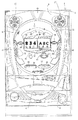
まず、遊技機の一例である弾球遊技機1の全体の構成について説明する。図1は弾球遊技機1を正面からみた正面図である。 First, an overall configuration of a bullet ball gaming machine 1 which is an example of a gaming machine will be described. FIG. 1 is a front view of the ball game machine 1 as seen from the front.
弾球遊技機1は、縦長の方形状に形成された外枠(図示せず)と、外枠の内側に開閉可能に取り付けられた遊技枠とで構成される。また、弾球遊技機1は、遊技枠に開閉可能に設けられている額縁状に形成されたガラス扉枠2を有する。遊技枠は、外枠に対して開閉自在に設置される前面枠(図示せず)と、機構部品等が取り付けられる機構板(図示せず)と、それらに取り付けられる種々の部品(後述する遊技盤6を除く)と、を含む構造体である。
The bullet ball gaming machine 1 includes an outer frame (not shown) formed in a vertically long rectangular shape and a game frame attached to the inside of the outer frame so as to be openable and closable. Further, the bullet ball gaming machine 1 has a
図1に示すように、弾球遊技機1は、額縁状に形成されたガラス扉枠2を有する。ガラス扉枠2の下部表面には打球供給皿(上皿)3がある。打球供給皿3の下部には、打球供給皿3に収容しきれない遊技球を貯留する余剰球受皿4、打球を発射する打球操作ハンドル(操作ノブ)5が設けられている。また、ガラス扉枠2の背面には、遊技盤6が着脱可能に取り付けられている。なお、遊技盤6は、それを構成する板状体と、その板状体に取り付けられた種々の部品とを含む構造体である。また、遊技盤6の前面には打ち込まれた遊技球が流下可能な遊技領域7が形成されている。
As shown in FIG. 1, the ball game machine 1 has a
遊技領域7中には、所定の始動条件の成立(たとえば、打球が第1始動入賞口14へ入賞)に基づいて各々が識別可能な複数種類の識別情報(たとえば、「0」〜「9」の全10種類の数字図柄)の変動表示を行なって表示結果を導出表示する第1特別図柄表示器8と、所定の始動条件の成立(たとえば、打球が第2始動入賞口16へ入賞)に基づいて各々が識別可能な複数種類の識別情報(たとえば、「C,E,F,H,J,L,O,P,S,U」の全10種類のアルファベット図柄)の変動表示を行なって表示結果を導出表示する第2特別図柄表示器9と、が間隔を隔てて配置されている。
In the
第1特別図柄表示器8の下には、その第1特別図柄表示器8に対応する識別情報(たとえば、「0」〜「9」の全10種類の数字図柄)の変動表示を行なって表示結果を導出表示する第1飾り変動表示部8kが設けられ、第2特別図柄表示器9の下にはその第2特別図柄表示器9に対応する識別情報(たとえば、「A〜J」の全10種類のアルファベット図柄)の変動表示を行なって表示結果を導出表示する第2飾り変動表示部9kが設けられている。
Below the first
本実施の形態では、第1特別図柄表示器8および第2特別図柄表示器9はそれぞれ7セグメントLED表示器により構成されている。第1飾り変動表示部8kおよび第2飾り変動表示部9kは、それぞれ液晶表示装置(LCD)により構成され、左・中・右の3つの表示領域(たとえば、第1飾り変動表示部8kにおいては第1飾り図柄8a〜8c、第2飾り変動表示部9kにおいては第2飾り図柄9a〜9c)に識別情報が表示制御されるものである。これら左・中・右の3つの表示領域で変動表示される飾り図柄は、左図柄、中図柄、右図柄と呼ばれる。
In the present embodiment, the first
第1特別図柄表示器8の表示結果が大当りの発生する第1特図特定表示結果(たとえば、奇数図柄)の場合には、第1飾り変動表示部8kの表示結果も大当りが発生する第1飾り特定表示結果(たとえば、左図柄、中図柄、右図柄が同一となる図柄組合せ、すなわちゾロ目)となるように制御され、第2特別図柄表示器9の表示結果が大当りの発生する第2特図特定表示結果(たとえば、「C,E,F,H,J」の図柄)となる場合には、第2飾り変動表示部9kの表示結果も大当りの発生する第2飾り特定表示結果(たとえば、左図柄、中図柄、右図柄が同一となる図柄組合せ、すなわちゾロ目)となるように制御され、両表示結果の整合性が保たれるように制御される。
When the display result of the first
なお、第1特別図柄表示器8で変動表示される識別情報は第1特別図柄と呼ばれ、第2特別図柄表示器9で変動表示される識別情報は第2特別図柄と呼ばれる。
The identification information variably displayed on the first
また、第1飾り変動表示部8kで変動表示される識別情報は第1飾り図柄と呼ばれ、第1特別図柄表示器8における第1特別図柄の変動表示の装飾効果を高めるために第1特別図柄の変動表示と所定の関係を有して変動表示される装飾的な意味合いがある図柄をいう。
Also, the identification information that is variably displayed on the first ornament
また、第2飾り変動表示部9kで変動表示される識別情報は第2飾り図柄と呼ばれ、第2特別図柄表示器9における第2特別図柄の変動表示の装飾効果を高めるために第2特別図柄の変動表示と所定の関係を有して変動表示される装飾的な意味合いがある図柄をいう。
In addition, the identification information that is variably displayed on the second ornament variation display unit 9k is called a second ornament symbol, and the second special
所定の関係には、たとえば、特別図柄の変動表示が開始されたときに飾り図柄の変動表示が開始される関係や、特別図柄の変動表示が終了し表示結果が表示されたときに飾り図柄の変動表示が終了し表示結果が表示される関係等が含まれる。 The predetermined relationship includes, for example, a relationship in which the decorative symbol variation display is started when the special symbol variation display is started, or the special symbol variation display is ended and the display result is displayed. This includes a relationship in which the variable display is terminated and the display result is displayed.
なお、本実施形態における弾球遊技機1では、定期的に実行されるタイマ割込み処理において次のような処理が行なわれることにより、第1特別図柄表示器8および第2特別図柄表示器9の変動表示の表示結果が決定される。
In the ball game machine 1 in the present embodiment, the following processing is performed in the timer interrupt processing that is periodically executed, so that the first
第1特別図柄表示器8および第2特別図柄表示器9の表示結果を決定するために実行することが必要な処理としては、共通の処理である特定更新処理、第1特別図柄表示器8専用の処理である第1抽出条件判定処理と第1抽出処理と第1表示結果決定処理、第2特別図柄表示器9専用の処理である第2抽出条件判定処理と第2抽出処理と第2表示結果決定処理、を含む処理が実行される。
Processes that need to be executed in order to determine the display results of the first
そして、弾球遊技機1は、第1表示結果決定処理により第1特別図柄表示器8の表示結果を第1特図特定表示結果とし特定遊技状態(大当り)とすることが決定されたときに、第1特別図柄表示器8に第1特図特定表示結果を、第1飾り変動表示部8kに第1飾り特定表示結果をそれぞれ表示した後に遊技者にとって有利な特定遊技状態としての大当りに制御する機能を有する。
When the ball game machine 1 determines that the display result of the first
また、第2表示結果決定処理により第2特別図柄表示器9の表示結果を第2特定表示結果とし特定遊技状態(大当り)とすることが決定されたとき、第2特別図柄表示器9に第2特図特定表示結果を、第2飾り変動表示部9kに第2飾り特定表示結果をそれぞれ表示した後に遊技者にとって有利な特定遊技状態としての大当りに制御する機能を有する。
When the second display result determination process determines that the display result of the second
なお、この実施の形態では、第1特別図柄表示器8に第1特図特定表示結果が、第1飾り変動表示部8kに第1飾り特定表示結果が導出表示されたことにより発生する特定遊技状態と、第2特別図柄表示器9に第2特図特定表示結果が、第2飾り変動表示部9kに第2飾り特定表示結果が導出表示されたことにより発生する特定遊技状態とを同一(たとえば、大当りラウンド数、入賞払出数、等)の特定遊技状態としているが、一方の特定遊技状態を他方の特定遊技状態と比べてさらに有利となるように構成してもよい。
In this embodiment, the first special figure specific display result is displayed on the first
また、この実施の形態では、第1特別図柄表示器8および第1飾り変動表示部8kと、第2特別図柄表示器9および第2飾り変動表示部9kとの2系統の表示部により識別情報の変動表示を行なう構成となっているが、これに限らず複数系統の表示部を備え、複数(2〜∞のうちの任意の自然数)の表示部にて識別情報の変動表示を行なう構成としてもよい。
In this embodiment, the identification information is displayed by two systems of display units including the first special
次に、第1特別図柄表示器8における変動表示に用いられる第1特別図柄の種類と、第1飾り変動表示部8kにおける変動表示に用いられる第1飾り図柄の種類と、第2特別図柄表示器9における変動表示に用いられる第2特別図柄の種類と、第2飾り変動表示部9kにおける変動表示に用いられる第2飾り図柄の種類と、について図2を参照し説明する。図2は、第1特別図柄表示器8,第1飾り変動表示部8k,第2特別図柄表示器9,および,第2飾り変動表示部9k各々の変動表示に用いられる図柄の種類を説明するための図である。なお、本実施形態においては、後述するようにセットされるモードに応じて、第1特別図柄表示器8、第1飾り変動表示部8k、第2特別図柄表示器9、および、第2飾り変動表示部9k各々の変動表示に用いられる図柄の数、種類が変更される。ここでは、基本的なモード(後述する突入モード1、転落モード3)がセットされているときの、図柄の数、種類について説明する。
Next, the type of the first special symbol used for the variable display in the first
第1特別図柄表示器8は、0〜9の10種類の数字からなる第1特別図柄を表示する。第1飾り変動表示部8kは、0〜9の10種類の数字からなる第1飾り図柄を表示する。
The first
第1特別図柄表示器8により奇数(1,3,5,7,9)の第1特別図柄が表示結果として導出表示されたときには第1特図特定表示結果となり、大当りが発生する。第1特別図柄表示器8により奇数が表示結果として導出表示されるときには、第1飾り変動表示部8kにゾロ目となる第1飾り特定表示結果が表示結果として導出表示される。
When the odd number (1, 3, 5, 7, 9) of the first special symbol is derived and displayed as the display result by the first
第1特別図柄表示器8により「7」が表示結果として導出表示されたときには確変図柄の表示結果となり、大当りが発生するばかりでなくその大当りが終了した後大当りの発生確率が通常遊技状態時に比べて向上した確変状態となる。なお、通常遊技状態とは、特別遊技状態(確変状態)および大当りとは異なる遊技状態のことである。
When “7” is derived and displayed by the first
第1特別図柄表示器8により「5」が表示結果として導出表示されたときには確変図柄および時短図柄の表示結果となり、後述するように、大当りが発生しするばかりでなくその大当りが終了した後大当りの発生確率が向上した確変状態となり、さらにその確変状態が終了した後時短回数の残り回数だけ時短制御が行なわれる。時短制御とは、後に詳述するが、第1特別図柄表示器8と第2特別図柄表示器9と後述する普通図柄表示器12との変動表示時間を通常よりも短縮して早期に表示結果を導出表示する制御である。この時短制御により、後述する保留記憶数が早期に消化され、保留記憶数の上限(たとえば「4」)を超えて発生した始動入賞が無効になってしまう状態を減少でき、短期間に頻繁に表示結果を導出表示して早期に当たりの表示結果を導出表示できるという遊技者にとって有利な遊技状態となる。
When “5” is derived and displayed as a display result by the first
なお、第1特別図柄表示器8により確変図柄としての「5」または「7」が表示結果として導出表示されるときには、第1飾り変動表示部8kに奇数図柄のいずれかのゾロ目が表示結果として導出表示される。
When “5” or “7” as the probability variation symbol is derived and displayed as the display result by the first
第1特別図柄表示器8により「3」が表示結果として導出表示されたときには、大当りが発生しするばかりでなく前述の時短制御が行なわれる。第1特別図柄表示器8により「3」が表示結果として導出表示されるときには、第1飾り変動表示部8kに「0」のゾロ目が表示結果として導出表示される。
When "3" is derived and displayed as a display result by the first
第1特別図柄表示器8により「1」または「9」が表示結果として導出表示されたときには、大当りのみが発生し、確変状態や時短制御は生じない。第1特別図柄表示器8により「1」または「9」が表示結果として導出表示されるときには、第1飾り変動表示部8kに偶数のゾロ目が表示結果として導出表示される。
When “1” or “9” is derived and displayed as a display result by the first
第1特別図柄表示器8により「0」または偶数図柄のいずれかが表示結果として導出表示されたときには、はずれとなり、大当り状態、確変状態、時短制御は生じない。第1特別図柄表示器8により「0」または偶数図柄のいずれかが表示結果として導出表示されるときには、第1飾り変動表示部8kにばらけ目(ゾロ目以外の組み合わせ)が表示結果として導出表示される。
When either “0” or an even number symbol is derived and displayed as a display result by the first
第1特図特定表示結果のうち、前述の確変状態が発生する第1特図特定表示結果(ここでは、「5,7」)を「第1特図特別表示結果(確変図柄)」といい、確変状態が発生しない第1特図特定表示結果(ここでは、「1,3,9」)を「第1特図非特別表示結果(非確変図柄)」という。 Among the first special figure specific display results, the first special figure specific display result (here, “5, 7”) in which the above-described probability variation state occurs is referred to as “first special figure special display result (probability variation symbol)”. The first special figure specific display result (here, “1, 3, 9”) in which the probability variation state does not occur is referred to as “first special figure non-special display result (non-probable variation symbol)”.
第2特別図柄表示器9は、「C,E,F,H,J,L,O,P,S,U」の10種類のアルファベットからなる第2特別図柄を表示する。第2飾り変動表示部9kは、A〜Jの10種類のアルファベットからなる第2飾り図柄を表示する。
The second
第2特別図柄表示器9により「C,E,F,H,J」が表示結果として導出表示されたときには第2特定表示結果となり、大当りが発生する。第2特別図柄表示器9により「C,E,F,H,J」が表示結果として導出表示されるときには、第2飾り変動表示部9kにゾロ目となる第2飾り特定表示結果が表示結果として導出表示される。
When "C, E, F, H, J" is derived and displayed as a display result by the second
第2特別図柄表示器9により「C」が表示結果として導出表示されたときには確変図柄の表示結果となり、大当りが発生するばかりでなくその大当りが終了した後に確変状態となる。
When “C” is derived and displayed as a display result by the second special
第2特別図柄表示器9により「E」が表示結果として導出表示されたときには確変図柄および時短図柄の表示結果となり、後述するように、大当りが発生するばかりでなくその大当りが終了した後に確変状態となり、さらにその確変状態が終了した後時短回数の残り回数だけ時短制御が行なわれる。
When “E” is derived and displayed as a display result by the second
なお、第2特別図柄表示器9により「C」または「E」が表示結果として導出表示されるときには、第2飾り変動表示部9kに「A〜E」図柄のいずれかのゾロ目が表示結果として導出表示される。
When "C" or "E" is derived and displayed as a display result by the second
第2特別図柄表示器9により「F」が表示結果として導出表示されたときには、大当りが発生するばかりでなく前述の時短制御が行なわれる。第2特別図柄表示器9により「F」が表示結果として導出表示されるときには、第2飾り変動表示部9kに「F」のゾロ目が表示結果として導出表示される。
When "F" is derived and displayed as a display result by the second
第2特別図柄表示器9により「H」または「J」が表示結果として導出表示されたときには、大当りのみが発生し、確変状態や時短制御は生じない。第2特別図柄表示器9により「H」または「J」が表示結果として導出表示されるときには、第2飾り変動表示部9kに「G」〜「J」のいずれかによるゾロ目が表示結果として導出表示される。
When “H” or “J” is derived and displayed as a display result by the second
第2特別図柄表示器9により「L,O,P,S,U」図柄のいずれかが表示結果として導出表示されたときには、はずれとなり、大当り状態、確変状態、時短制御は生じない。第2特別図柄表示器9により「L,O,P,S,U」図柄のいずれかが表示結果として導出表示されるときには、第2飾り変動表示部9kにばらけ目が表示結果として導出表示される。
When any of the “L, O, P, S, U” symbols is derived and displayed as a display result by the second
第2特図特定表示結果のうち、前述の確変状態が発生する第2特定表示結果(ここでは、「C,E」)を「第2特図特別表示結果(確変図柄)」といい、確変状態が発生しない第2特図特定表示結果(ここでは、「F,H,J」)を「第2特図非特別表示結果(非確変図柄)」という。 Among the second special figure specific display results, the second specific display result (here, “C, E”) in which the above-mentioned probability variation state occurs is called “second special figure special display result (probability variation symbol)”. The second special figure specific display result (here, “F, H, J”) in which no state occurs is referred to as “second special figure non-special display result (non-probable variation pattern)”.
なお、本実施の形態においては、第1特別図柄表示器8および第1飾り変動表示部8kと、第2特別図柄表示器9および第2飾り変動表示部9kとで表示する図柄の種類が各々異なる例について説明するが、これに限らず、第1特別図柄表示器8および第1飾り変動表示部8kと、第2特別図柄表示器9および第2飾り変動表示部9kとで表示する図柄の種類が同じであってもよい。
In the present embodiment, the types of symbols displayed on the first special
第1,第2の2系統の第1特別図柄表示器8、または、第2特別図柄表示器9のいずれか一方において特別表示結果が導出表示されて確変状態になれば、第1特別図柄表示器8と第2特別図柄表示器9との両方で特定表示結果となる確率が向上するように制御される。また、確変状態が発生すれば、第1特別図柄表示器8と第2特別図柄表示器9と普通図柄表示器12との変動表示時間が短縮される時短制御も実行される。第1,第2の2系統の第1特別図柄表示器8、または、第2特別図柄表示器9のいずれか一方において時短制御が実行される表示結果が導出表示されれば、第1特別図柄表示器8、第2特別図柄表示器9、および、普通図柄表示器12との変動表示時間が短縮される時短制御が、所定回数(たとえば100回)の範囲内で実行される。
If a special display result is derived and displayed in either one of the first and second two systems of the first
始動条件が成立(打球が第1始動入賞口14へ入賞)したときには、第1抽出手段は、数値データ更新手段によって更新された数値データ(たとえば、大当り判定用乱数等)を抽出する。第1抽出手段によって抽出された数値データは、保留記憶手段としての第1保留記憶バッファ(たとえば、主基板31に搭載されるRAM55(図3参照))に抽出順番を特定可能に記憶される。第1特別図柄表示器8の下部には、この保留記憶手段としての第1保留記憶バッファに記憶されている数値データの個数を遊技者に報知するための第1特別図柄保留記憶表示領域10が設けられている。このように記憶される数値データは、第1始動入賞記憶データとも呼ばれる。
When the start condition is satisfied (the hit ball wins the first start winning opening 14), the first extraction means extracts numerical data (for example, a big hit determination random number) updated by the numerical data update means. The numerical data extracted by the first extracting means is stored in a first reserved storage buffer (for example, a RAM 55 (see FIG. 3) mounted on the main board 31) as a reserved storage means so that the extraction order can be specified. Below the first
この第1特別図柄保留記憶表示領域10は、4つの表示領域に分かれ、有効始動入賞(この実施の形態では、第1保留記憶バッファに記憶される数値データの記憶数が4未満のときに打球が第1始動入賞口14に入賞)がある毎に表示色を変化させ、第1特別図柄表示器8の変動表示が開始される毎に表示色が変化している表示領域を1減らす。
The first special symbol reserved
始動条件が成立(打球が第2始動入賞口16へ入賞)したときには、第2抽出手段は、数値データ更新手段によって更新された数値データ(たとえば、大当り判定用乱数等)を抽出する。第2抽出手段によって抽出された数値データは、保留記憶手段としての第2保留記憶バッファ(たとえば、主基板31に搭載されるRAM55(図3参照))に抽出順番を特定可能に記憶される。第2特別図柄表示器9の下部には、この保留記憶手段としての第2保留記憶バッファに記憶されている数値データの個数を遊技者に報知するための第2特別図柄保留記憶表示領域11が設けられている。このように記憶される数値データは、第2始動入賞記憶データとも呼ばれる。
When the start condition is satisfied (the hit ball wins the second start winning opening 16), the second extraction means extracts numerical data (for example, a big hit determination random number) updated by the numerical data update means. The numerical data extracted by the second extracting means is stored in a second reserved storage buffer (for example, RAM 55 (see FIG. 3) mounted on the main board 31) as the reserved storage means so that the extraction order can be specified. Below the second
この第2特別図柄保留記憶表示領域11は、4つの表示領域に分かれ、有効始動入賞(この実施の形態では、第2保留記憶バッファに記憶される数値データの記憶数が4未満のときに打球が第2始動入賞口16に入賞)がある毎に表示色を変化させ、第2特別図柄表示器9の変動表示が開始される毎に表示色が変化している表示領域を1減らす。
The second special symbol reserved
なお、第1保留記憶バッファに記憶される数値データは、第1特別図柄表示器8の変動表示の開始条件が成立したときに第1特別図柄表示器8の変動表示を開始するための始動条件である。第2保留記憶バッファに記憶される数値データは、第2特別図柄表示器9の変動表示の開始条件が成立したときに第2特別図柄表示器9の変動表示を開始するための始動条件である。このため、各保留記憶バッファに記憶される数値データは、保留記憶データとも呼ばれる。
The numerical data stored in the first reserved storage buffer is the starting condition for starting the variable display of the first
また、この実施の形態では、第1保留記憶バッファおよび第2保留記憶バッファには、抽出手段(たとえば、S312)によって抽出された数値データ(たとえば、大当り判定用乱数、等)のうち未だ開始条件(たとえば、大当り遊技状態および前回の変動表示の終了)が成立していない数値データが予め定められた上限数として4個まで記憶される。なお、第1保留記憶バッファおよび第2保留記憶バッファに記憶可能となる数値データの上限数は上記のものに限らず、たとえば、上限数を20(または0〜∞のうち任意の整数)としてもよい。また、所定条件が成立した(たとえば、表示結果が特別表示結果となったことに基づいて特定遊技状態に移行する)ことに基づいて、上限値を変更する(たとえば、4個から20個に変更する)構成としてもよい。 Further, in this embodiment, the first reserved storage buffer and the second reserved storage buffer still have start conditions among the numerical data (for example, the big hit determination random number, etc.) extracted by the extraction means (for example, S312). Up to four pieces of numerical data that are not established (for example, the big hit gaming state and the end of the previous variation display) are stored as a predetermined upper limit number. The upper limit number of numerical data that can be stored in the first hold storage buffer and the second hold storage buffer is not limited to the above, and for example, the upper limit number may be 20 (or any integer from 0 to ∞). Good. Further, the upper limit value is changed (for example, changed from 4 to 20) based on the fact that the predetermined condition is satisfied (for example, the display result is changed to the specific gaming state based on the special display result). It may be configured.
第1特別図柄表示器8の下方には、遊技球が入賞可能な第1始動入賞口14が設けられている。第1始動入賞口14に入った入賞球は、遊技盤6の背面に導かれ、第1始動口スイッチ62によって検出される。
Below the first
また、第2特別図柄表示器9の下方には、遊技球が入賞可能な第2始動入賞口16を有する可変入賞装置17が設けられている。第2始動入賞口16に入った入賞球は、遊技盤6の背面に導かれ、第2始動口スイッチ67によって検出される。また、第2始動入賞口16を有する開閉動作を行なう可変入賞装置17には、左右一対の可動片が設けられている。可変入賞装置17の可動片は、ソレノイド74によって開状態とされる。ソレノイド74により可変入賞装置17の可動片が開状態となることにより、遊技球が第2始動入賞口16に入賞し易くなり(始動入賞し易くなり)、遊技者にとって有利な状態となる。
Also, below the second
第1始動入賞口14の下方には、第1特別図柄表示器8に第1特図特定表示結果が導出表示されたことに基づく大当りにおいて、ソレノイド72によって開状態とされる第1特別可変入賞装置20が設けられている。第1特別可変入賞装置20は、内部に第1大入賞口21を備えている。ソレノイド72は、第1特別可変入賞装置20の前面に設けられている開閉扉を開閉する手段である。
Below the first start winning opening 14, a first special variable prize that is opened by the
第1特別可変入賞装置20の第1大入賞口21には、V入賞領域とV入賞領域とは異なる10カウント入賞領域が備えられている。第1大入賞口20から入賞して、遊技盤6の背面に導かれた入賞球のうち、一方(V入賞領域)に入った入賞球は第1V入賞スイッチ64で検出され、もう一方(10カウント入賞領域)に入った入賞球は第1カウントスイッチ63で検出される。遊技盤6の背面には、第1大入賞口21内の経路を切り換えるためのソレノイド73も設けられている。
The first special winning
可変入賞装置17の下方には、第2特別図柄表示器9に第2特図特定表示結果が導出表示されたことに基づく大当りにおいて、ソレノイド75によって開状態とされる第2特別可変入賞装置22が設けられている。第2特別可変入賞装置22は、内部に第2大入賞口23を備えている。ソレノイド75は、第2特別可変入賞装置22の前面に設けられている開閉扉を開閉する手段である。
Below the variable winning
第2特別可変入賞装置22の第2大入賞口23には、V入賞領域とV入賞領域とは異なる10カウント入賞領域が備えられている。第2大入賞口23から入賞して、遊技盤6の背面に導かれた入賞球のうち、一方(V入賞領域)に入った入賞球は第2V入賞スイッチ69で検出され、もう一方(10カウント入賞領域)に入った入賞球は第2カウントスイッチ68で検出される。遊技盤6の背面には、第2大入賞口23内の経路を切り換えるためのソレノイド73も設けられている。
The second special winning
なお、この実施の形態では、第1特別図柄表示器8に第1特図特定表示結果が導出表示されたことに基づいて開閉する第1特別可変入賞装置20と第2特別図柄表示器9に特定表示結果が導出表示されたことに基づいて開閉する第2特別可変入賞装置22とを備えているが、特別可変入賞装置を1つだけ備えるように構成してもよい。すなわち、第1特別図柄表示器8に第1特図特定表示結果が導出表示されたことに基づいて開閉制御される特別可変入賞装置と、第2特別図柄表示器9に第2特図特定表示結果が導出表示されたことに基づいて開閉制御される特別可変入賞装置と、を同一の特別可変入賞装置を用いて構成してもよい。
In this embodiment, the first special variable winning
また、この実施の形態では、第2特別図柄表示器9の始動条件成立に関わる可変入賞装置17を備える構成として説明するが、これに限らず、たとえば、変動表示部の数だけ可変入賞装置を設けるように構成してもよい。すなわち、この実施の形態では、第2特別図柄表示器9の始動条件成立に関わる可変入賞装置17を備えているが、さらに、第1特別図柄表示器8の始動条件成立に関わる可変入賞装置15をさらに備えてもよい。また、この実施の形態では、可変入賞装置を1つだけ備える構成において、可変入賞装置が1つの変動表示部(第2特別図柄表示器9)の始動条件の成立に関わる例を示した。しかし、これに限らず、可変入賞装置を1つだけ備える構成において、可変入賞装置が2つの変動表示部(第1特別図柄表示器8,第2特別図柄表示器9)の始動条件の成立に関わるようにしてもよい。その場合には、可変入賞装置の始動入賞口に遊技球が入賞したときにいずれの変動表示部(たとえば、第1特別図柄表示器8または第2特別図柄表示器9のいずれか)にて変動表示を実行するかを選択する構成としてもよく、また、2つの変動表示部(たとえば、第1特別図柄表示器8,第2特別図柄表示器9)について予め定められた所定の順序(たとえば、第1特別図柄表示器8と第2特別図柄表示器9とを交互に変動表示)で変動表示を実行するように構成してもよい。
Moreover, although this embodiment demonstrates as a structure provided with the variable winning
第2飾り変動表示部9kの下方には、「○」および「×」と付された一対のLEDからなる普通図柄表示器12が設けられている。この普通図柄表示器12は、普通図柄と呼ばれる複数種類の識別情報(たとえば、「○」および「×」)を変動表示可能なものである。
Below the second decoration variation display portion 9k, a
第1ゲート28を遊技球が通過し第1ゲートスイッチ61で検出されると、または第2ゲート29を遊技球が通過して第2ゲートスイッチ66で検出されると、普通図柄当り判定用乱数が抽出されて主基板31に搭載されるRAM55の普通図柄バッファに格納される。この実施の形態では、RAM55の普通図柄バッファに記憶可能な普通図柄当り判定用乱数の記憶数の上限は、4個となっている。そして、普通図柄バッファに記憶される普通図柄当り判定用乱数の記憶数が上限に達していなければ、つまり、普通図柄バッファに記憶される普通図柄当り判定用乱数の記憶数が4個に達していなければ、普通図柄当り判定用乱数が抽出される。そして、普通図柄表示器12において普通図柄の表示状態が変化(「○」および「×」が交互に点灯)する変動表示を開始できる状態であれば、普通図柄表示器12において普通図柄の変動表示が開始される。普通図柄表示器12において表示状態が変化する変動表示を開始できる状態でなければ、普通図柄当り判定用乱数を普通図柄バッファに格納することで普通図柄当り判定用乱数の記憶数が1増加する。また、普通図柄表示器12の右側には、普通図柄当り判定用乱数の記憶数を表示する所定数(この実施の形態では4つ)のLEDを有する普通図柄保留記憶表示器18が設けられている。この普通図柄保留記憶表示器18は、第1,第2ゲート28,29を遊技球が通過し、第1,第2ゲートスイッチ61,66で遊技球が検出される毎に点灯するLEDを1つ増やす。そして、普通図柄表示器12にて普通図柄(たとえば、「○」および「×」)の変動表示が開始される毎に点灯しているLEDを1減らす。
When a game ball passes through the
この実施の形態では、普通図柄表示器12にて、「○」と「×」の付された上下のランプ(点灯時に図柄が視認可能になる)が交互に点灯することによって普通図柄の変動表示が行なわれ、変動表示は通常では標準変動時間(たとえば、29.2秒)継続する。そして、変動表示の終了時に「○」の付された上側のランプが点灯すれば当りとなる。当りとするか否かは、第1,第2ゲート28,29を遊技球が通過し、第1,第2ゲートスイッチ61,66で遊技球が検出されたときに抽出された数値データ(普通図柄当り判定用乱数)の値が所定の普通図柄当り判定値と合致したか否かによって決定される。普通図柄表示器12における変動表示の表示結果が当りである場合には、可変入賞装置17が所定回数、所定時間だけ開状態になって遊技球が第2始動入賞口16に入賞しやすい状態になる。すなわち、可変入賞装置17の状態は、普通図柄の停止図柄が当り図柄である場合に、遊技者にとって不利な状態から有利な状態に変化する。
In this embodiment, the
なお、上記の特別遊技状態として特図時短状態に制御することにより、遊技者にとって通常遊技状態よりも有利な状態とするようにしてもよい。特図時短状態では、第1特別図柄表示器8,第1飾り変動表示部8k,第2特別図柄表示器9,第2飾り変動表示部9kにおいて変動表示が所定回数(たとえば、100回)実行されるまで、第1特別図柄表示器8,第1飾り変動表示部8k,第2特別図柄表示器9,第2飾り変動表示部9kおよび普通図柄表示器12の変動表示時間が通常遊技状態より短縮される。さらに、可変入賞装置17において、開放時間と開放回数とのうちの一方または双方が通常遊技状態より高められる。可変入賞装置17の開放時間または開放回数が通常遊技状態より高められることにより、第2始動入賞口16への始動入賞が起こりやすくなり、所定期間内での第2特別図柄表示器8,第2飾り変動表示部9kにおける変動表示回数が増加して当り図柄となる確率が通常遊技状態より高まるため、遊技者にとってさらに有利な状態となる。
It should be noted that by controlling the special game state to the special figure short time state, the player may be in a state more advantageous than the normal game state. In the special symbol short-time state, the variable display is executed a predetermined number of times (for example, 100 times) on the first
なお、上述した確変状態は、時短状態よりもさらに遊技者にとって有利な状態となるため、一方(または複数のうちのいずれか1つまたは任意の自然数個)の特別遊技状態を確変状態とし、他方(または残りの複数のうちの1つまたは任意の自然数個)の特別遊技状態を時短状態とすることにより特別遊技状態に格差をつけるように構成してもよい。また、この場合には、特別遊技状態として時短状態に制御する(他の特別遊技状態に比べて遊技者にとって不利となる特別遊技状態に制御する)変動表示部の大当りとなる確率を特別遊技状態として確変状態に制御する(他の特別遊技状態に比べて遊技者にとって有利となる特別遊技状態に制御する)変動表示部の大当りとなる確率よりも高くなるように構成してもよい。このように構成することにより、遊技者の興趣をさらに向上させることができる。 Note that the probability variation state described above is more advantageous to the player than the time-short state, so one (or any one of a plurality or any natural number) of the special game state is a probability variation state, and the other A special gaming state may be differentiated by setting the special gaming state (or one of the remaining plurality or any natural number) to a short-time state. In this case, the special game state is controlled to the short-time state (the special game state which is disadvantageous for the player as compared with other special game states). It may be configured to be higher than the probability of being a big hit of the variable display portion (controlled to a special gaming state advantageous to the player as compared with other special gaming states). By comprising in this way, the interest of a player can be improved further.
また、特別遊技状態は上記のものに限らず、遊技者に有利となる遊技制御を特別遊技状態とすればよい。以下、この遊技制御を大当りに直接的には係わらないもの(特定遊技状態中以外)と大当りに直接的に係わるもの(特定遊技状態中)とに分けて説明する。すなわち、特定遊技状態に加える特別遊技状態とは、特定遊技状態とは別の特別遊技状態のことであってもよいし、また特定遊技状態を含む特別遊技状態のことであってもよい。 Further, the special game state is not limited to the above, and the game control that is advantageous to the player may be set to the special game state. Hereinafter, this game control will be described separately for those that are not directly related to the jackpot (except during the specific gaming state) and those that are directly related to the jackpot (in the specific gaming state). That is, the special game state added to the specific game state may be a special game state different from the specific game state, or may be a special game state including the specific game state.
先ず、特別遊技状態の当りに直接的には係わらない遊技制御としては、第1特別図柄表示器8、第2特別図柄表示器9および普通図柄に対しての時間短縮(時短)制御または確率変動(確変)制御、電役(たとえば、可変入賞装置17)の開放期間の延長制御、特別図柄および普通図柄に対しての始動通過領域の増設制御(たとえば、遊技盤6に設置される入賞口(図示しない)を特別図柄の始動入賞口として設定変更する制御)、賞球数の増加制御(たとえば、入賞に伴う賞球を通常遊技状態時の13個から15個に増加する制御)、または所定領域への通過率向上制御(たとえば、第1始動入賞口14の上流側に打球規制装置を設け、該打球規制装置の作動により始動入賞率を向上する制御)を特別遊技状態とすることができ、さらには始動入賞に基づいて変動表示される図柄の停止図柄が所定の図柄の組合せになると開放する所定の電動役物への入賞があると所定の権利が発生または継続する弾球遊技機に本発明を適用した場合には、特定領域への入賞率向上制御を特別遊技状態としてもよい。
First, game control that is not directly related to the special game state includes time shortening (time reduction) control or probability variation for the first
一方、特別遊技状態の当りに直接的に係わる遊技制御としては、ラウンド上限数の向上制御、カウント上限数の向上制御、特別可変入賞装置20,22の開放延長制御、または特別可変入賞装置20,22によって開放された大入賞口21,23への入賞に伴う賞球数の増加制御を特別遊技状態とすることができる。なお、上記の遊技制御を組合せて特別遊技状態とすることもできる。さらには、特別遊技状態への突入条件(所定条件の成立)および特別遊技状態の終了条件については、本実施形態中に記載のものに限定せず、特別遊技状態を発生させるための判定用乱数、特別遊技状態を終了させるための判定用乱数(確変判定用乱数)、遊技履歴(たとえば、時間、リーチ回数、所定入賞口への入賞回数、通過回数等)、入賞、およびサブゲーム(たとえば、ジャンケンなどで遊技者自身が選択できるものを含む)の4つの要素のうちいずれか1つまたは任意の組合せを、特別遊技状態への突入条件または特別遊技状態の終了条件に設定するものであればよい。
On the other hand, as the game control directly related to the special game state, the round upper limit improvement control, the count upper limit improvement control, the special variable prize-winning
遊技盤6の遊技領域7の左右周辺には、遊技中に点滅表示される装飾ランプ25が設けられ、下部には、入賞しなかった打球が取り込まれるアウト口26がある。また、遊技領域7の外側の左右上部には、所定の音声出力として効果音や音声を発声する2つのスピーカ27が設けられている。遊技領域7の外周上部、外周左部および外周右部には、前面枠に設けられた天枠ランプ40、枠ランプ左41および枠ランプ右42が設けられている。また、枠ランプ左41の近傍には賞球残数があるときに点灯する賞球ランプ51が、枠ランプ右42の近傍には補給球が切れたときに点灯する球切れランプ52が、設けられている。
A
次に、リーチ表示態様(リーチ)について説明する。本実施形態におけるリーチ表示態様(リーチ)とは、停止した図柄が大当り図柄の一部を構成しているときに未だ停止していない図柄については変動表示が行なわれていること、および全てまたは一部の図柄が大当り図柄の全てまたは一部を構成しながら同期して変動表示している状態である。 Next, the reach display mode (reach) will be described. In the present embodiment, the reach display mode (reach) means that the symbols that have not been stopped when the stopped symbols constitute a part of the jackpot symbol, and that all or one of them is displayed. This is a state in which the symbols of the parts are displayed in a synchronized manner while constituting all or part of the jackpot symbol.
本実施形態では、たとえば、第1特別図柄表示器8および第2特別図柄表示器9におけるリーチ表示態様とは、特定表示結果(第1特別図柄表示器8の大当り図柄である「1,3,5,7,9」、第2特別図柄表示器9の大当り図柄である「C,E,F,H,J」)が点滅表示している状態をリーチ表示態様またはリーチという。
In the present embodiment, for example, the reach display mode in the first
また、第1飾り変動表示部8kおよび第2飾り変動表示部9kにおけるリーチ表示態様とは、予め定められた図柄が停止することで当りとなる有効ラインが定められ、その有効ライン上の一部の表示領域に予め定められた図柄が停止しているときに未だ停止していない有効ライン上の表示領域において変動表示が行なわれている状態(たとえば、第1飾り変動表示部8k,第2飾り変動表示部9kにおける左、中、右の表示領域のうち左、右の表示領域には同一の図柄が停止表示されている状態で中の表示領域は未だ変動表示が行なわれている状態)、および有効ライン上の表示領域の全てまたは一部の図柄が大当り図柄の全てまたは一部を構成しながら同期して変動表示している状態(たとえば、第1飾り変動表示部8k,第2飾り変動表示部9kにおける左、中、右の表示領域の全てに変動表示が行なわれており、常に同一の図柄が揃っている状態で変動表示が行なわれている状態)をリーチ表示態様またはリーチという。
In addition, the reach display mode in the first decoration
また、リーチの際に、通常と異なる演出がランプや音で行なわれることがある。この演出をリーチ演出という。また、リーチの際に、キャラクタ(人物等を模した演出表示であり、図柄(特別図柄等)とは異なるもの)を表示させたり、第1飾り変動表示部8kおよび/または第2飾り変動表示部9kの背景の表示態様(たとえば、色等)を変化させたりすることがある。このキャラクタの表示や背景の表示態様の変化をリーチ演出表示という。
In addition, during the reach, an unusual performance may be performed with a lamp or sound. This production is called reach production. In addition, during the reach, a character (an effect display imitating a person or the like, which is different from a symbol (special symbol or the like)) is displayed, or the first ornament
また、図示しないが弾球遊技機1には打球操作ハンドル5を操作することにより駆動モータを駆動し、駆動モータの回転力を利用して遊技球を遊技領域7に発射する打球発射装置45が設けられている。打球発射装置45から発射された遊技球は、遊技盤6に遊技領域7を囲むように円形状に載設された打球レールを通って遊技領域7に入り、その後、遊技領域7を下りてくる。
Although not shown, the ball game machine 1 has a
打球が第1始動入賞口14に入り第1始動口スイッチ62で検出されると、第1特別図柄表示器8の変動表示を開始できる状態であれば(たとえば、大当り遊技終了または前回の変動表示の終了)、第1特別図柄表示器8の変動表示を開始する。第1特別図柄表示器8の変動表示を開始できる状態でなければ、第1保留記憶バッファに記憶される数値データ(たとえば、大当り判定用乱数等)の記憶数を1増やし、第1特別図柄保留記憶表示領域10の表示色を変化させる。
When the hit ball enters the first start winning opening 14 and is detected by the first
また、打球が第2始動入賞口16に入り第2始動口スイッチ67で検出されると、第2特別図柄表示器9の変動表示を開始できる状態であれば(たとえば、大当り遊技終了または前回の変動表示の終了)、第2特別図柄表示器9の変動表示を開始する。第2特別図柄表示器9の変動表示を開始できる状態でなければ、第2保留記憶バッファに記憶される数値データ(たとえば、大当り判定用乱数等)の記憶数を1増やし、第2特別図柄保留記憶表示領域11の表示色を変化させる。
Further, when the hit ball enters the second
第1特別図柄表示器8の変動表示は、一定時間が経過したときに停止する。停止時の第1特別図柄表示器8が大当り図柄となると、大当り遊技状態に移行する。すなわち、一定時間経過するまで、または、所定個数(たとえば、10個)の打球が第1大入賞口21に入賞するまで第1特別可変入賞装置20によって第1大入賞口21が開放される。なお、第1特別可変入賞装置20によって第1大入賞口21が開閉されてから一定期間経過するまで、または、所定個数(たとえば、10個)の打球が第1大入賞口21に入賞するまでが大当り遊技状態における1ラウンドである。そして、第1特別可変入賞装置20による第1大入賞口21の開放中に打球が第1大入賞口21内のV入賞領域に入賞し、第1V入賞スイッチ64で検出されると、継続権が発生し第1特別可変入賞装置20により第1大入賞口21の開放が再度行なわれる。継続権の発生は、所定回数(たとえば、15ラウンド)許容される。
The fluctuation display of the first
第1特別図柄表示器8の変動停止時の停止図柄が確率変動を伴う大当り図柄(特別表示結果:確変図柄)である場合には、大当り遊技状態に制御され、大当り遊技状態終了後に、次に大当りとなる確率が通常遊技状態よりも高い確変状態という遊技者にとってさらに有利な状態となる。
When the stop symbol at the time of the fluctuation stop of the first
第2特別図柄表示器9の変動表示は、一定時間が経過したときに停止する。停止時の第2特別図柄表示器9が大当り図柄となると、大当り遊技状態に移行する。すなわち、一定時間経過するまで、または、所定個数(たとえば、10個)の打球が第2大入賞口23に入賞するまで第2特別可変入賞装置22によって第2大入賞口23が開放される。なお、第2特別可変入賞装置22によって第2大入賞口23が開閉されてから一定期間経過するまで、または、所定個数(たとえば、10個)の打球が第2大入賞口23に入賞するまで、が大当り遊技状態における1ラウンドである。そして、第2特別可変入賞装置22による第2大入賞口23の開放中に打球が第2大入賞口23内のV入賞領域に入賞し、第2V入賞スイッチ69で検出されると、継続権が発生し第2特別可変入賞装置22により第2大入賞口23の開放が再度行なわれる。継続権の発生は、所定回数(たとえば、15ラウンド)許容される。
The fluctuation display on the second
第2特別図柄表示器9の変動停止時の停止図柄が確率変動を伴う大当り図柄(特別表示結果:確変図柄)である場合には、大当り遊技状態に制御され、大当り遊技状態終了後に、次に当りとなる確率が通常遊技状態よりも高い確変状態という遊技者にとってさらに有利な状態となる。
When the stop symbol at the time of the fluctuation stop of the second
なお、本発明に係る特定遊技状態は、上記に限らず以下に示す1〜5の制御のうちいずれか1つの制御または組合せた制御を実行する状態であればよい。
1.打球の入賞を容易にする第1の状態と、打球が入賞できないまたは入賞し難い第2の状態と、に変化可能な可変入賞装置に対して所定時間連続的または間欠的に第1の状態にする制御
2.特定の入賞または通過領域での打球の検出を介在させ、打球の入賞を容易にする第1の状態と、打球が入賞できないまたは入賞し難い第2の状態と、に変化可能な可変入賞装置に対して所定時間連続的または間欠的に第1の状態にする制御
3.打球の入賞に関わらず所定数の景品球を直接排出する制御
4.有価価値を有する記憶媒体(カードやレシート等)に対して有価数を加算する制御
5.得点があることに基づいて遊技可能な弾球遊技機に対して得点を付与する制御
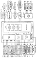
図3は、本実施形態に係る弾球遊技機1の回路構成の概要を表したブロック図である。
In addition, the specific game state according to the present invention is not limited to the above, and may be a state in which any one of the following controls 1 to 5 or a combination of controls is executed.
1. A variable winning device that can change between a first state that facilitates winning of a hit ball and a second state in which the hit ball cannot win or that is difficult to win, is changed to the first state continuously or intermittently for a predetermined time. 1. Control to A variable winning device that can change between a first state that makes it easy to win a hit ball and a second state that makes it difficult or difficult to win a ball, with the detection of a hit ball in a specific winning or passing area. 2. Control for setting to the first state continuously or intermittently for a predetermined time. 3. Control to discharge a predetermined number of prize balls directly regardless of the winning of the hit ball. 4. Control for adding a valuable number to a storage medium (card, receipt, etc.) having a valuable value FIG. 3 is a block diagram showing an outline of the circuit configuration of the ball game machine 1 according to the present embodiment.
主基板31には、プログラムに従って弾球遊技機1を制御する基本回路53が搭載されている。基本回路53は、ゲーム制御用のプログラム等を記憶するROM54、ワークメモリとして使用される記憶手段としてのRAM55、プログラムに従って遊技の信号を制御するCPU56、および表示制御基板80等に制御信号を送信するI/Oポート部57を含む。この実施の形態では、ROM54,RAM55はCPU56に内蔵されている。すなわち、CPU56は、1チップマイクロコンピュータである。なお、CPU56はROM54に格納されているプログラムに従って制御を実行するので、以下、CPU56が実行する(または、処理を行なう)ということは、具体的には、CPU56がプログラムに従って制御を実行することである。このことは、主基板31以外の他の基板に搭載されているCPUについても同様である。また、この実施の形態で用いられる遊技制御用マイクロコンピュータとは、主基板31に搭載されるCPU56、ROM54、RAM55、I/Oポート部57、等の周辺回路のことである。
On the
また、第1ゲートスイッチ61、第1始動口スイッチ62、第1カウントスイッチ63、第1V入賞スイッチ64、クリアスイッチ65、第2ゲートスイッチ66、第2始動口スイッチ67、第2カウントスイッチ68、第2V入賞スイッチ69、余剰球受皿4がいっぱいになったときに検出する満タンスイッチ(図示しない)、カウントスイッチ短絡信号(図示しない)、からの信号を基本回路53に与えるスイッチ回路32、第1特別可変入賞装置20を開閉するソレノイド72、第1大入賞口21内に設けられたシーソーを可動するソレノイド73、可変入賞装置17を開閉するソレノイド74、第2特別可変入賞装置22を開閉するソレノイド75、第2大入賞口23内に設けられたシーソーを可動するソレノイド76、等を基本回路53からの指令に従って駆動するソレノイド回路33、電源投入時に基本回路53をリセットするためのシステムリセット回路(図示しない)、基本回路53から与えられるデータに従って、大当り遊技状態の発生を示す大当り情報、等の情報出力信号をホールコンピュータ等の外部装置に対して出力する情報出力回路34、も主基板31に搭載されている。
Also, the
基本回路53は、LED駆動回路71に対して第1特別図柄表示器8および第2特別図柄表示器9等を駆動させるための駆動信号を出力する。LED駆動回路71には、第1特別図柄表示器8、第2特別図柄表示器9、普通図柄表示器12、第1特別図柄保留記憶表示領域10、第2特別図柄保留記憶表示領域11、普通図柄保留記憶表示器18が接続されている。
The
主基板31は、第1特別図柄表示器8および第2特別図柄表示器9各々において、変動表示を開始した後に表示結果を導出表示する表示制御を行なうための回路が形成されている。遊技制御用マイクロコンピュータは、プログラムに従い、駆動信号を第1特別図柄表示器8および第2特別図柄表示器9各々に出力し表示制御を行なう。これにより、主基板31と第1特別図柄表示器8および第2特別図柄表示器9との間にドライバ回路やマイクロコンピュータを搭載した特別図柄表示器用の制御基板等を設け、主基板31からの指令信号に基づき制御基板等により第1特別図柄表示器8および第2特別図柄表示器9の表示制御を行なう場合と比較して、大当り判定の結果を確実に間違いなく表示させることができる。
The
主基板31は、第1特別図柄保留記憶表示領域10および第2特別図柄保留記憶表示領域11各々において、対応する保留記憶バッファに記憶されている数値データの記憶数を報知するための回路が形成されている。遊技制御用マイクロコンピュータは、プログラムに従い、保留記憶バッファの保留記憶数に応じた駆動信号を第1特別図柄保留記憶表示領域10および第2特別図柄保留記憶表示領域11各々に出力し制御を行なう。また、主基板31は、普通図柄表示器12の表示制御を行なう。
The
主基板31に設けられた遊技制御用マイクロコンピュータ(CPU56およびROM54,RAM55等の周辺回路)は、プリペイドカード等が挿入されることによって球貸しを可能にするカードユニット50、遊技盤6に設けられた複数の入賞口にて遊技球の入賞を検出したことにより賞球払い出しを行なう球払出装置44、を制御する払出制御基板36に払出制御信号を送信する。また、遊技制御用マイクロコンピュータは、打球操作ハンドル5を操作することにより打球発射装置45を駆動制御して遊技球を遊技領域7に向けて発射制御する発射制御基板37に発射制御信号を送信する。
A game control microcomputer (peripheral circuits such as a
さらに、遊技制御用マイクロコンピュータは、表示制御基板80に演出制御コマンド(演出制御信号)を送信する。演出制御コマンドを受信することにより表示制御基板80に設けられた表示制御用マイクロコンピュータ(表示制御用CPU(図示しない)、RAM(図示しない)、ROM(図示しない)、I/Oポート部(図示しない)、等の周辺回路)が第1飾り変動表示部8kおよび第2飾り変動表示部9kの表示制御を行なう。演出制御コマンドには、第1飾り変動表示部8kの表示を指定する第1コマンドと、第2飾り変動表示部9kの表示を指定する第2コマンドとが含まれ、表示制御用マイクロコンピュータは、受信したコマンドに応じた変動表示部(第1飾り変動表示部8kまたは第2飾り変動表示部9k)を表示制御する。
Further, the game control microcomputer transmits an effect control command (effect control signal) to the
表示制御用CPUは、ROMに格納されたプログラムに従って動作し、主基板31から演出制御コマンドを受信すると、受信した演出制御コマンドに従って受信したコマンドに応じた変動表示部(第1飾り変動表示部8kまたは第2飾り変動表示部9k)の表示制御を行なう。具体的には、画像表示を行なう表示制御機能および高速描画機能を有するVDP(図示しない)により変動表示部の表示制御を行なう。表示制御用CPUは、受信した演出制御コマンドに従ってキャラクタROM(図示しない)から必要なデータを読み出す。キャラクタROMは、第1飾り変動表示部8kおよび第2飾り変動表示部9kに表示される画像の中でも使用頻度の高いキャラクタ画像データ、具体的には、人物、怪物、文字、図形または記号等を予め格納しておくためのものである。
The display control CPU operates in accordance with a program stored in the ROM, and when receiving the effect control command from the
そして、表示制御用CPUはキャラクタROMから読み出したデータをVDPに出力する。VDPは表示制御用CPUからデータが入力されたことに基づいて動作する。この実施の形態では、第1飾り変動表示部8kの表示制御を行なう第1VDP(図示しない)と、第2飾り変動表示部9kの表示制御を行なう第2VDP(図示しない)と、の2つのVDPが表示制御基板80に搭載されている。なお、変動表示部を3つとした場合にはVDPが3つ搭載される。すなわち、変動表示部の数に対応した数のVDPが表示制御基板80に搭載される。また、第1VDPおよび第2VDPは、それぞれ、表示制御用CPUとは独立した二次元のアドレス空間を持ち、そこに第1VRAM(図示しない)および第2VRAM(図示しない)をマッピングしている。なお、1つのVDPで複数の変動表示部の表示制御を行なう構成としてもよい。たとえば、第1飾り変動表示部8kと第2飾り変動表示部9kとの両方の表示制御を行なうVDPを1つ備える構成としてもよい。
Then, the display control CPU outputs the data read from the character ROM to the VDP. The VDP operates based on data input from the display control CPU. In this embodiment, two VDPs, a first VDP (not shown) that performs display control of the first decoration
第1VDPまたは第2VDPはキャラクタ画像データに従って受信したコマンドに応じた変動表示部(第1飾り変動表示部8kまたは第2飾り変動表示部9k)に表示するための画像データを生成し、第1VDPは第1VRAMに、第2VDPは第2VRAMに展開する。第1RAMは第1VDPによって生成された画像データを展開するためのフレームバッファメモリであり、第2VRAMは第2VDPによって生成された画像データを展開するためのフレームバッファメモリである。そして、受信したコマンドに応じた変動表示部(第1飾り変動表示部8kまたは第2飾り変動表示部9k)に出力する。
The first VDP or the second VDP generates image data to be displayed on the variation display unit (the first ornament
また、この実施の形態では、表示制御基板80に設けられた表示制御用マイクロコンピュータが音声出力基板70にスピーカ27の駆動信号を出力し、スピーカ27の音声出力制御を行なうともに、ランプドライバ基板35にランプ・LEDの駆動信号を出力し、弾球遊技機1に設けられたランプ・LEDの発光制御を行なう。すなわち、表示制御基板80に搭載される表示制御用マイクロコンピュータは、主基板31から送信される第1飾り変動表示部8kおよび第2飾り変動表示部9kの表示制御、ランプ・LEDの点灯制御、遊技音発生等の演出の制御に関する指令情報としての演出制御コマンド(制御信号)に基づいて第1飾り変動表示部8k、第2飾り変動表示部9k、スピーカ27、弾球遊技機1に設けられるランプ・LED等の発光体の制御を行なう演出制御用マイクロコンピュータである。
In this embodiment, the display control microcomputer provided on the
次に、この実施の形態の弾球遊技機1での制御に用いられる乱数値を発生させるためのランダムカウンタについて説明する。図4は、遊技制御用マイクロコンピュータが遊技制御に用いる各種ランダムカウンタを説明するための図である。図4には、ランダムカウンタの一例として、ランダムカウンタR1〜R9の9種類のランダムカウンタが示されている。 Next, a random counter for generating a random value used for control in the ball game machine 1 of this embodiment will be described. FIG. 4 is a diagram for explaining various random counters used by the game control microcomputer for game control. FIG. 4 shows nine types of random counters R1 to R9 as an example of the random counter.
R1は、第1特別図柄表示器8(第1飾り変動表示部8kも含む)および第2特別図柄表示器9(第2飾り変動表示部9kも含む)のそれぞれの変動表示について大当りを発生させるか否かを事前にランダムに判定するために用いられる乱数値を発生させるための大当り判定用のランダムカウンタであり、「0」からカウントアップしてその上限である「658」までカウントアップし、再度「0」からカウントアップし直すように構成されている。このR1は、2msec毎に加算更新されることとなる。第1始動口スイッチ62または第2始動口スイッチ67により有効な始動入賞が検出されると、それに応じてこのR1のカウント値が抽出されて第1始動入賞記憶のデータまたは第2始動入賞記憶のデータとしてRAM55に記憶される。そして、第1特別図柄表示器8および第2特別図柄表示器9のそれぞれについて、特別図柄の変動表示を開始する前の段階で、そのようにRAM55に記憶された抽出値が予め定められた大当り判定値と一致(合致)するか否かが判断される。この判断において、一致した場合には、大当り図柄を変動表示の表示結果として導出表示し大当りを発生させることが決定されて、前述した大当り遊技状態の制御が行なわれ、一致しない場合には、はずれ図柄を変動表示の表示結果として導出表示することが決定されて、遊技状態が変化しない。確変状態以外の通常の確率状態においては、大当り判定値がたとえば2つの数値に設定される。確変状態においては、大当り判定値が複数個の数値(この場合、大当り判定値は、大当り判定に偏りが生じなくするために、数値順番が隣接した数値とならないように設定される)に設定されることにより、通常遊技状態に比べて大当りの発生確率が向上する。
R1 generates a big hit for each variable display of the first special symbol display 8 (including the first decoration
図4の各ランダムカウンタについての範囲の欄に示されている数値範囲は、このようなランダムカウンタのカウント範囲であって、R1で説明したように初期値から上限値までカウントアップした後、再度初期値からカウントアップし直すものである。したがって、説明を簡略化するために、以下の各種カウンタの説明においては、カウント範囲およびカウント方法についての説明を省略する。 The numerical range shown in the range column for each random counter in FIG. 4 is the count range of such a random counter, and after counting up from the initial value to the upper limit value as described in R1, again, Counting up from the initial value. Therefore, in order to simplify the description, the description of the count range and the counting method is omitted in the following description of the various counters.
R2は、通常遊技状態であるときであって大当りを発生させることが事前決定されているときに確変状態に制御させるか否かの判定(確変開始判定)と、確変状態であるときであって確変状態を終了させるか否かの判定(確変終了判定)と、をランダムに決定するために用いられる乱数値を発生させるためのランダムカウンタである。2msec毎に更新され、0から更新されてその上限である99まで更新された後再度0から更新される。 R2 is a normal game state and a determination whether or not to control to the probability variation state when it is predetermined to generate a big hit (probability change start determination), and when the probability variation state. This is a random counter for generating a random value used for determining whether to end the probability variation state (probability variation end determination) and at random. It is updated every 2 msec, updated from 0 and updated to 99 which is the upper limit, and then updated from 0 again.
本実施の形態における確変開始判定については、通常遊技状態であるときにおいて、R2から抽出した乱数値と、後述するセットされた突入モードから特定される突入判定値とを比較することにより、確変状態へ制御するか否か判定される。また、確変終了判定については、確変状態であるときにおいて、R2から抽出した乱数値と、後述するセットされた転落モードから特定される転落判定値とを比較することにより、確変状態を終了するか否か判定される。 With respect to the probability change start determination in the present embodiment, in the normal gaming state, the probability change state is determined by comparing a random value extracted from R2 with an entry determination value specified from a set entry mode described later. It is determined whether or not to control. In addition, regarding the probability change end determination, whether the probability change state is ended by comparing a random value extracted from R2 with a fall determination value specified from a set fall mode, which will be described later, in the probability change state. It is determined whether or not.
R3は、R1を用いた大当り判定により大当りを発生させることが事前決定されているときに、どの種類の大当り図柄を第1特別図柄表示器8(第1飾り変動表示部8kも含む)および第2特別図柄表示器9(第2飾り変動表示部9kも含む)に表示させるかをランダムに決定するために用いられる乱数値を発生させるためのランダムカウンタである。2msec毎に更新され、0から更新されてその上限である9まで更新された後再度0から更新される。
When R3 is determined in advance to generate a big hit by the big hit determination using R1, any kind of big hit symbol is included in the first special symbol display 8 (including the first decoration
なお、本実施の形態における大当り図柄は、R2を用いて当該大当り終了後に確変状態に制御することが決定されているときには確変図柄(第1特別図柄表示器8においては「5,7」、第2特別図柄表示器9においては「C,E」)から、確変状態に制御されないことが決定されているときには確変図柄以外の大当り図柄(第1特別図柄表示器8においては「1,3,9」、第2特別図柄表示器9においては「F,H,J」)から、このランダムカウンタR3の抽出値に従って決定される。
Note that the jackpot symbol in the present embodiment is a probability variation symbol (“5, 7” in the first
たとえば、第1特別図柄表示器8における確変図柄としては、ランダムカウンタR3の抽出値が「0」のとき「5」が、ランダムカウンタR3の抽出値が「1」のとき「7」が、ランダムカウンタR3の抽出値が「2」のとき「5」が…、ランダムカウンタR3の抽出値が「9」のとき「7」が、それぞれ決定される。
For example, the probability variation symbol in the first
また、たとえば、第1特別図柄表示器8における確変図柄以外の大当り図柄としては、ランダムカウンタR3の抽出値が「0」のとき「1」が、ランダムカウンタR3の抽出値が「1」のとき「3」が、ランダムカウンタR3の抽出値が「2」のとき「9」が、ランダムカウンタR3の抽出値が「3」のとき「1」が、…、ランダムカウンタR3の抽出値が「9」のとき「1」が、それぞれ決定される。
Further, for example, as a jackpot symbol other than the probability variation symbol in the first
第2特別図柄表示器9における確変図柄および確変図柄以外の大当り図柄にの決定方法は、前述したような第1特別図柄表示器8における確変図柄および確変図柄以外の大当り図柄の決定方法と同様である。具体的には、次のようになる。
The method for determining the probability variation symbol and the jackpot symbol other than the probability variation symbol in the second
たとえば、第2特別図柄表示器9における確変図柄としては、ランダムカウンタR3の抽出値が「0」のとき「C」が、ランダムカウンタR3の抽出値が「1」のとき「E」が、ランダムカウンタR3の抽出値が「2」のとき「C」が…、ランダムカウンタR3の抽出値が「9」のとき「E」が、それぞれ決定される。
For example, the probability variation symbol in the second
また、たとえば、第1特別図柄表示器8における確変図柄以外の大当り図柄としては、ランダムカウンタR3の抽出値が「0」のとき「F」が、ランダムカウンタR3の抽出値が「1」のとき「H」が、ランダムカウンタR3の抽出値が「2」のとき「J」が…、ランダムカウンタR3の抽出値が「9」のとき「F」が、それぞれ決定される。
Further, for example, as a jackpot symbol other than the probability variation symbol in the first
本実施の形態においては、第1特別図柄表示器8の図柄として「5,7」のいずれかが決定されたときには、第1飾り変動表示部8kにおいて奇数図柄のゾロ目が導出表示されるように、第2特別図柄表示器9の図柄として「C,E」のいずれかが決定されたときには、第2飾り変動表示部9kにおいて「A〜E」のいずれかの図柄のゾロ目が導出表示されるように制御される。
In the present embodiment, when any one of “5, 7” is determined as the symbol of the first
また、R3を用いて、第1特別図柄表示器8の図柄として「1,3,9」のいずれかが決定されたときには、第1飾り変動表示部8kにおいて偶数図柄のゾロ目が導出表示されるように、第2特別図柄表示器9の図柄として「F,H,J」のいずれかが決定されたときには、第2飾り変動表示部9kにおいて「G〜J」のいずれかの図柄のゾロ目が導出表示されるように制御される。
Further, when any one of “1, 3, 9” is determined as the symbol of the first
R4は、第1特別図柄表示器8および第2特別図柄表示器9のそれぞれについて、はずれとなる表示結果における停止図柄を事前にランダムに決定するために用いられる乱数値を発生させるためのはずれ図柄決定用のランダムカウンタである。R4は、2msecごとおよび割込み処理余り時間にそれぞれ加算更新される。
R4 is an outlier symbol for generating a random value used for determining in advance a stop symbol in the display result that is out of place for each of the first
ここで、R4等の所定のランダムカウンタにおいて行なわれる割込み処理余り時間におけるカウントアップ動作について説明する。遊技制御用マイクロコンピュータのCPU56は、定期的な割込み処理の実行により、各種制御を行なうが、ある割込み処理について、割込み処理が実行された後に、その割込み処理の次回の実行開始までの期間は割込み処理待ち状態となる。そのような割込み処理待ち状態である割込み処理の余り時間において、無限ループを利用してランダムカウンタの加算更新処理を繰返し実行することを割込み処理余り時間におけるカウントアップという。
Here, the count-up operation in the remaining interrupt processing time performed in a predetermined random counter such as R4 will be described. The
なお、本実施の形態におけるはずれ図柄は、R1を用いて大当りに制御されないことが決定されているときには、はずれ図柄(第1特別図柄表示器8においては「0,2,4,6,8」、第2特別図柄表示器9においては「L,O,P,S,U」)から、このランダムカウンタR4の抽出値に従って決定される。
When it is determined that the lost symbol in the present embodiment is not controlled by big hits using R1, the lost symbol ("0, 2, 4, 6, 8" in the first special symbol display 8). In the second
たとえば、第1特別図柄表示器8におけるはずれ図柄としては、ランダムカウンタR4の抽出値が「0」のとき「0」が、ランダムカウンタR4の抽出値が「1」のとき「2」が、ランダムカウンタR4の抽出値が「2」のとき「4」が…、ランダムカウンタR4の抽出値が「13」のとき「6」が、決定される。第2特別図柄表示器9におけるはずれ図柄についても、第1特別図柄表示器8におけるはずれ図柄と同様である。
For example, as the off symbol in the first
なお、本実施の形態においては、R4を用いて、第1特別図柄表示器8の図柄として「0,2,4,6,8」のいずれかが決定されたときには、第1飾り変動表示部8kにおいてゾロ目とならないはずれ図柄が導出表示されるように、第2特別図柄表示器9の図柄として「L,O,P,S,U」のいずれかが決定されたときには、第2飾り変動表示部9kにおいてゾロ目とならないはずれ図柄が導出表示されるように制御される。
In the present embodiment, when one of “0, 2, 4, 6, 8” is determined as the symbol of the first
R5は、第1特別図柄表示器8(第1飾り変動表示部8kも含む)および第2特別図柄表示器9(第2飾り変動表示部9kも含む)の変動表示時間をランダムに決定するために用いられる乱数値を発生するための数値データ更新手段(ランダムカウンタ)である。R5のカウント値は、2msec毎および割込処理余り時間に所定数ずつ加算されることとなる。特別図柄の変動開始時等の所定のタイミングで変動時間決定用のランダムカウンタR5から抽出されたカウンタの値により、変動時間が決定される。
R5 randomly determines the variation display time of the first special symbol display 8 (including the first decoration
R6は、第1特別図柄表示器8(第1飾り変動表示部8kも含む)および第2特別図柄表示器9(第2飾り変動表示部9kも含む)のそれぞれについて、前述の大当り判定においてはずれとする判定がされたときに、変動表示中に前述したリーチ表示態様を形成する(以下、リーチはずれという)かリーチ表示態様を形成しない(以下、非リーチはずれという)かをランダムに判定するために用いられる乱数値を発生させるためのリーチ判定用のランダムカウンタである。このR6は、2msecごとおよび割込み処理余り時間に実行される。第1特別図柄表示器8、第1飾り変動表示部8kおよび第2特別図柄表示器9、第2飾り変動表示部9k各々に停止させる図柄を決定する前の段階で、R6から抽出されたカウント値が予め定められたリーチ判定値と一致するか否かが判断される。そして、これらの値が一致した場合には、リーチはずれとすることが判定され、表示結果がはずれとなる変動表示中にリーチ状態とする制御が行なわれる。一方、これらの値が一致した場合には、非リーチはずれとすることが判定され、表示結果がはずれとなる変動表示中にリーチ状態としない制御が行なわれる。
R6 is different from the jackpot determination for each of the first special symbol display 8 (including the first decoration
R7は、普通図柄表示器12の変動表示について当りを発生させるか否かを事前にランダムに判定するために用いられる乱数値を発生させるためのランダムカウンタである。第1ゲートスイッチ61または第2ゲートスイッチ66により有効な始動通過が検出されると、それに応じて、このR7のカウント値が抽出されて通過記憶データとしてRAM55に記憶される。そして、普通図柄の変動表示を開始する前の段階で、その抽出値が予め定められた当り判定値と一致するか否かが判断され、一致した場合には普通図柄の当りを発生させることが決定されて前述のような制御が行なわれ、不一致の場合にははずれとすることが決定されて前述のような制御が行なわれる。
R7 is a random counter for generating a random value used to randomly determine in advance whether or not to generate a hit for the fluctuation display of the
R8は、確変状態に制御するか否かの確変開始判定に用いられる突入モードを、ランダムに決定するために用いられる乱数値を発生させるためのランダムカウンタである。R8のカウント値は、2msec毎および割込処理余り時間に所定数ずつ加算されることとなる。なお、本実施形態における突入モードは、確変開始判定において確変状態に制御するための突入判定値を特定するものである。確変開始判定においては、R8からの抽出値に基づき決定された突入モードから特定される突入判定値と、R2から抽出した値が一致するか否かを判定し、一致するときに確変状態への制御を開始する判定が行なわれる。 R8 is a random counter for generating a random value used to randomly determine the entry mode used for determining whether or not to control the probability variation state. The count value of R8 is incremented by a predetermined number every 2 msec and the interruption processing surplus time. Note that the rush mode in the present embodiment specifies a rush determination value for controlling the probability variation state in the probability variation start determination. In the probability change start determination, it is determined whether or not the rush determination value specified from the rush mode determined based on the extracted value from R8 and the value extracted from R2 match, and when they match, the probability change state is entered. A determination is made to start control.
R9は、確変状態を終了するか否かの判定に用いられる転落モードを、ランダムに決定するために用いられる乱数値を発生させるためのランダムカウンタである。R9のカウント値は、2msec毎に所定数ずつ加算されることとなる。なお、本実施形態における転落モードは、確変終了判定において確変状態を終了するための転落判定値を特定するものである。確変終了判定においては、R9からの抽出値に基づき決定された転落モードから特定される転落判定値と、R2から抽出した値が転落判定値が一致するか否かを判定し、一致するときに確変状態への制御を終了する判定が行なわれる。 R9 is a random counter for generating a random value used for randomly determining a fall mode used for determining whether or not to end the probability variation state. The count value of R9 is incremented by a predetermined number every 2 msec. Note that the fall mode in the present embodiment specifies a fall determination value for ending the probability variation state in the probability variation end determination. In the probability variation end determination, it is determined whether or not the fall determination value specified from the fall mode determined based on the extraction value from R9 and the value extracted from R2 match the fall determination value. A determination is made to end the control to the probability variation state.
以上に示したような大当り判定機能、はずれ停止図柄決定機能、大当り図柄決定機能、リーチ判定機能、変動時間選択機能、普通図柄当り判定機能等の機能、確変開始判定機能、および、確変終了判定機能は、遊技制御用マイクロコンピュータ53の制御機能により実現される。
Big hit determination function, outage stop symbol determination function, jackpot symbol determination function, reach determination function, variation time selection function, normal symbol hit detection function, probability variation start determination function, and probability variation end determination function as described above Is realized by the control function of the
図5は、遊技制御用マイクロコンピュータにより実行される各種処理に用いられる各種判定値を記憶したデータテーブルを説明するための図である。本実施の形態におけるデータテーブルは、前述した主基板31に搭載されるROM54に予め記憶されている。
FIG. 5 is a diagram for explaining a data table storing various determination values used in various processes executed by the game control microcomputer. The data table in the present embodiment is stored in advance in the
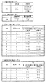
図5(a)は、大当りを発生させるか否かの判定に用いられる大当り判定値を記憶した大当り判定用テーブルを説明するための図である。本実施の形態における大当り判定用テーブルは、遊技状態が通常遊技状態であるか確変状態であるかに応じて、大当り判定値の数が異なるように記憶されている。大当り判定は、第1始動入賞口14または第2始動入賞口16へ入賞したときにR1から抽出された乱数値が、通常遊技状態であるときに通常時の大当り判定値と一致するか否か、また、確変状態であるときに確変時の大当り判定値と一致するか否かにより行なわれる。
FIG. 5A is a diagram for explaining a jackpot determination table storing a jackpot determination value used for determining whether or not to generate a jackpot. The jackpot determination table in the present embodiment is stored so that the number of jackpot determination values varies depending on whether the gaming state is the normal gaming state or the probability variation state. The big hit determination is whether or not the random value extracted from R1 when winning the first start winning opening 14 or the second
具体的に、遊技状態が通常遊技状態であるときには、R1から抽出した乱数の値が通常時の大当り判定値である「7,17」のいずれかと一致するときに、大当りとする判定が行なわれる。 Specifically, when the gaming state is the normal gaming state, when the value of the random number extracted from R1 coincides with any one of “7, 17” which is the normal big hit determination value, the big hit determination is performed. .
一方、遊技状態が確変状態であるときには、R1から抽出した乱数の値が確変時の大当り判定値である「7,107,207,307,407,507,607,17,117,217」のいずれかと一致するときに、大当りとする判定が行なわれる。 On the other hand, when the gaming state is in a probabilistic state, the random number value extracted from R1 is one of “7, 107, 207, 307, 407, 507, 607, 17, 117, 217” which is a jackpot determination value at the time of the probable variation. When it matches, it is determined to be a big hit.
なお、本実施の形態における大当り判定用テーブルは、確変時の大当り判定値の数の方が、通常時の大当り判定値の数よりも多くなるように、予め記憶されている。たとえば、確変時の大当り判定値は「10個」、通常時の大当り判定値は「2個」、予め記憶されている。これにより、確変状態であるときに大当りとする判定が行なわれる確率を、通常遊技状態であるときに大当りとする判定が行なわれる確率よりも高くすることができる。 Note that the jackpot determination table in the present embodiment is stored in advance so that the number of jackpot determination values at the time of probability change is larger than the number of jackpot determination values at the normal time. For example, the jackpot determination value at the time of probability change is “10”, and the normal jackpot determination value is “2”, which is stored in advance. This makes it possible to increase the probability of making a big hit determination when in the probable state than the probability of making a big hit determination in the normal gaming state.
図5(b)は、変動表示中にリーチ状態を発生させるか否かに用いられるリーチ判定値を記憶したリーチ判定用テーブルを説明するための図である。本実施の形態におけるリーチ判定用テーブルは、遊技状態がリーチを高確率で発生させる高確率時であるか高確率時よりも低確率でリーチを発生させる通常確率時であるかに応じて、リーチ判定値の数が異なるように記憶されている。リーチ判定は、第1始動入賞口14または第2始動入賞口16へ入賞したときにR6から抽出された乱数値が、遊技状態が高確率時であるときに高確率時用のリーチ判定値と一致するか否か、または、遊技状態が通常確率時であるときに通常確率時用のリーチ判定値と一致するか否かにより行なわれる。
FIG. 5B is a diagram for explaining a reach determination table that stores reach determination values used to determine whether or not a reach state is generated during variable display. The reach determination table in the present embodiment has a reach depending on whether the gaming state is a high probability of generating a reach with a high probability or a normal probability of generating a reach with a lower probability than a high probability. The number of determination values is stored differently. The reach determination is performed when the random value extracted from R6 when winning the first start winning opening 14 or the second
具体的に、遊技状態が高確率時であるときには、R6から抽出した乱数の値が、高確率時のリーチ判定値である「0〜15」のいずれかと一致するときに、リーチを発生させる判定が行なわれる。 Specifically, when the gaming state is at a high probability, the determination to generate reach when the random number value extracted from R6 matches any of the reach determination values “0 to 15” at the high probability. Is done.
一方、遊技状態が通常確率時であるときには、R6から抽出した乱数の値が、通常確率時のリーチ判定値である「0〜3」のいずれかと一致するときに、リーチを発生させる判定が行なわれる。 On the other hand, when the gaming state is at the normal probability, a determination to generate reach is performed when the random number value extracted from R6 matches any of the reach determination values “0 to 3” at the normal probability. It is.
なお、本実施の形態におけるリーチ判定用テーブルは、高確率時のリーチ判定値の数の方が、通常確率時のリーチ判定値の数よりも多くなるように、予め記憶されている。たとえば、高確率時のリーチ判定値は「16個」、通常確率時のリーチ判定値は「4個」、予め記憶されている。これにより、高確率時であるときにリーチとする判定が行なわれる確率を、通常確率時であるときにリーチとする判定が行なわれる確率よりも高くすることができる。 Note that the reach determination table in the present embodiment is stored in advance so that the number of reach determination values at the high probability is larger than the number of reach determination values at the normal probability. For example, the reach determination value at high probability is “16”, and the reach determination value at normal probability is “4”. As a result, the probability of determining reach when the probability is high can be made higher than the probability of determining reach when the probability is normal.
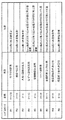
図5(c)は、確変状態に制御するか否か、すなわち確変状態に突入させるか否かに用いられる突入判定値を記憶した確変突入判定用テーブルを説明するための図である。 FIG. 5C is a diagram for explaining a probability variation entry determination table that stores the entry determination value used to determine whether or not to control the probability variation state, that is, whether to enter the probability variation state.
本実施の形態における確変突入判定用テーブルは、R8から抽出した乱数値に基づき突入モード1〜突入モード9うちから突入モードが決定される。たとえば、R8から抽出した乱数値が、「0」のときには突入モード1が、「1」のときには突入モード2が、…「8」のときには突入モード9が、突入モードとして決定される。
In the probability variation entry determination table in the present embodiment, the entry mode is determined from the entry mode 1 to the
さらに、確変突入判定用テーブルは、R2から抽出した乱数値に基づき、確変開始判定に用いられる突入判定値がそれぞれの突入モード毎に予め記憶されている。たとえば、突入モード1については、第1特別図柄表示器8側の確変開始判定に用いられる突入判定値として「0〜49」が、第2特別図柄表示器9側の確変突入判定に用いられる突入判定値として「0〜49」が、予め記憶されている。これにより、突入モード1がセットされているときには、第1特別図柄表示器8側で確変状態に制御する判定がなされる確率と、第2特別図柄表示器9側で確変状態に制御する判定がなされる確率とが同じになるように、確変突入判定が行なわれる。
Further, in the probability variation entry determination table, the entry determination value used for the probability change start determination is stored in advance for each entry mode based on the random value extracted from R2. For example, in the rush mode 1, “0-49” is used as the rush determination value used for the probability change start determination on the first
また、本実施の形態における確変突入判定用テーブルは、第1特別図柄表示器8側の確変開始判定に用いられる突入判定値の数と、第2特別図柄表示器9側の確変開始判定に用いられる突入判定値の数とが、異なる突入モードが含まれるように複数種類の突入モード毎に突入判定値が予め記憶されている。
The probability variation entry determination table in the present embodiment is used for the number of entry determination values used for the probability variation start determination on the first
たとえば、突入モード2について、第1特別図柄表示器8側の確変開始判定に用いられる突入判定値として「0〜55」が、第2特別図柄表示器9側の確変突入判定に用いられる突入判定値として「0〜41」が、予め記憶されている。また、突入モード3について、第1特別図柄表示器8側の確変開始判定に用いられる突入判定値として「0〜59」が、第2特別図柄表示器9側の確変突入判定に用いられる突入判定値として「0〜33」が、予め記憶されている。突入モード4について、第1特別図柄表示器8側の確変開始判定に用いられる突入判定値として「0〜64」が、第2特別図柄表示器9側の確変突入判定に用いられる突入判定値として「0〜20」が、予め記憶されている。以下同様に突入モード毎に第1特別図柄表示器8側の確変開始判定に用いられる突入判定値と、第2特別図柄表示器9側の確変突入判定に用いられる突入判定値とが各々記憶されている。
For example, for the
これにより、突入モード2〜9のいずれかがセットされているときには、第1特別図柄表示器8側で確変状態に制御する判定がなされる確率と、第2特別図柄表示器9側で確変状態に制御する判定がなされる確率とが異なるように、確変突入判定が行なわれる。
Thereby, when any of the
なお、本実施の形態において、突入モード2〜突入モード4については、第2特別図柄表示器9側で確変状態に制御する判定がなされる確率よりも、第1特別図柄表示器8側で確変状態に制御する判定がなされる確率の方が段階的に高くなるように、各々突入判定値が記憶されている。また、突入モード6〜突入モード8については、第1特別図柄表示器8側で確変状態に制御する判定がなされる確率よりも、第2特別図柄表示器9側で確変状態に制御する判定がなされる確率の方が段階的に高くなるように、各々突入判定値が記憶されている。
In the present embodiment, for the
また、突入モード5について、第1特別図柄表示器8側の確変開始判定に用いられる突入判定値として「0〜67」が予め記憶されているが、第2特別図柄表示器9側の確変突入判定は一つも記憶されていない。これにより、突入モード5がセットされているときには、第1特別図柄表示器8側で確変状態に制御する判定がなされる確率が他の突入モードと比較し最も高くなるが、第2特別図柄表示器9側で確変状態に制御する判定がなされないように、確変突入判定が行なわれる。突入モード9について、第2特別図柄表示器9側の確変開始判定に用いられる突入判定値として「0〜67」が予め記憶されているが、第1特別図柄表示器8側の確変突入判定は一つも記憶されていない。これにより、突入モード9がセットされているときには、第2特別図柄表示器9側で確変状態に制御する判定がなされる確率が他の突入モードと比較し最も高くなるが、第1特別図柄表示器8側で確変状態に制御する判定がなされないように、確変突入判定が行なわれる。
In the
図5(d)は、確変状態を終了するか否かに用いられる転落判定値を記憶した確変転落判定用テーブルを説明するための図である。 FIG. 5D is a diagram for explaining a probability variation fall determination table storing a fall decision value used to determine whether or not to end the probability variation state.
本実施の形態における確変転落判定用テーブルは、R9から抽出した乱数値に基づき転落モード1〜転落モード5のうちから転落モードが決定される。たとえば、R9から抽出した乱数値が、「0」のときには転落モード1が、「1」のときには転落モード2が、…「4」のときには転落モード5が、転落モードとして決定される。
In the probability variation fall determination table in the present embodiment, the fall mode is determined from the fall mode 1 to the
さらに、確変転落判定用テーブルは、R2から抽出した乱数値に基づき、確変終了判定に用いられる転落判定値がそれぞれの転落モード毎に予め記憶されている。たとえば、転落モード3については、第1特別図柄表示器8側の確変終了判定に用いられる転落判定値として「0〜4」が、第2特別図柄表示器9側の確変転落判定に用いられる転落判定値として「0〜4」が、予め記憶されている。これにより、転落モード3がセットされているときには、第1特別図柄表示器8側で確変状態を終了する判定がなされる確率と、第2特別図柄表示器9側で確変状態を終了する判定がなされる確率とが同じになるように、確変転落判定が行なわれる。
Further, in the probability variation fall determination table, the fall determination value used for the probability variation end determination is stored in advance for each fall mode based on the random value extracted from R2. For example, in the
また、本実施の形態における確変転落判定用テーブルは、第1特別図柄表示器8側の確変終了判定に用いられる転落判定値の数と、第2特別図柄表示器9側の確変終了判定に用いられる転落判定値の数とが、異なる転落モードが含まれるように複数種類の転落モード毎に転落判定値が予め記憶されている。
Further, the probability variation fall determination table in the present embodiment is used for the number of fall determination values used for the probability variation end determination on the first
たとえば、転落モード1について、第1特別図柄表示器8側の確変終了判定に用いられる転落判定値として「0」が、第2特別図柄表示器9側の確変転落判定に用いられる転落判定値として「0〜8」が、予め記憶されている。また、転落モード2について、第1特別図柄表示器8側の確変終了判定に用いられる転落判定値として「0〜2」が、第2特別図柄表示器9側の確変転落判定に用いられる転落判定値として「0〜6」が、予め記憶されている。転落モード4について、第1特別図柄表示器8側の確変終了判定に用いられる転落判定値として「0〜6」が、第2特別図柄表示器9側の確変転落判定に用いられる転落判定値として「0〜2」が、予め記憶されている。転落モード5について、第1特別図柄表示器8側の確変終了判定に用いられる転落判定値として「0〜8」が、第2特別図柄表示器9側の確変転落判定に用いられる転落判定値として「0」が、予め記憶されている。
For example, for the fall mode 1, “0” is used as the fall determination value used for the probability change end determination on the first
これにより、転落モード1,2,4,5のいずれかがセットされているときには、第1特別図柄表示器8側で確変状態を終了する判定がなされる確率と、第2特別図柄表示器9側で確変状態を終了する判定がなされる確率とが異なるように、確変転落判定が行なわれる。
Thus, when any of the
なお、本実施の形態において、転落モード4,5については、第2特別図柄表示器9側で確変状態を終了する判定がなされる確率よりも、第1特別図柄表示器8側で確変状態を終了する判定がなされる確率の方が段階的に高くなるように、各々転落判定値が記憶されている。また、転落モード1,2については、第1特別図柄表示器8側で確変状態を終了する判定がなされる確率よりも、第2特別図柄表示器9側で確変状態を終了する判定がなされる確率の方が段階的に高くなるように、各々転落判定値が記憶されている。
In the present embodiment, for the
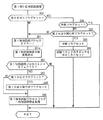
図6は、遊技制御用マイクロコンピュータにより実行される遊技制御用メイン処理およびタイマ割込処理を説明するためのフローチャートである。図6においては、(a)に遊技制御用メイン処理が示され、(b)にタイマ割込処理が示されている。このタイマ割込処理は、たとえば2msec毎に1回実行される。 FIG. 6 is a flowchart for explaining game control main processing and timer interrupt processing executed by the game control microcomputer. In FIG. 6, (a) shows the main process for game control, and (b) shows the timer interrupt process. This timer interruption process is executed once every 2 msec, for example.
(a)に示す遊技制御用メイン処理においては、まずS11において内蔵デバイスレジスタ等の初期化をする初期化処理が行なわれ、S12においてランダムカウンタを更新するための乱数更新処理が行なわれる。S12における乱数更新処理は前述のR4〜R7の値を更新するための処理である。なお、本実施形態において、2msec毎の割込処理が実行された後次回の割込処理が実行されるまでの割込待ち処理余り時間に、無限にS12の処理が繰返し行なわれることとなる。 In the main process for game control shown in (a), an initialization process for initializing the built-in device register and the like is first performed in S11, and a random number update process for updating the random counter is performed in S12. The random number update process in S12 is a process for updating the values of R4 to R7 described above. In the present embodiment, the process of S12 is repeatedly performed indefinitely during the interrupt waiting process surplus time until the next interrupt process is executed after the interrupt process is executed every 2 msec.
次に、(b)タイマ割込処理について説明する。タイマ割込が発生すると、CPU56は、レジスタの退避処理(S21)を行なった後、S22〜S36の割込処理である遊技制御処理を実行する。遊技制御処理において、CPU56は、まず、スイッチ回路32を介して、第1ゲートスイッチ61、第1始動口スイッチ62、第1カウントスイッチ63、第1V入賞スイッチ64、クリアスイッチ65、第2ゲートスイッチ66、第2始動口スイッチ67、第2カウントスイッチ68、第2V入賞スイッチ69、等のスイッチの検出信号を入力し、それらの状態判定を行なう(スイッチ処理:S22)。
Next, (b) timer interrupt processing will be described. When a timer interrupt occurs, the
そして、CPU56は、第1特別図柄プロセス処理を行なう(S23)。第1特別図柄プロセス制御では、遊技状態に応じて第1特別図柄表示器8、第1特別可変入賞装置20、等を所定の順序で制御するための第1特別図柄プロセスフラグに従って該当する処理が選び出されて実行される。そして、第1特別図柄プロセスフラグの値は、遊技状態に応じて各処理中に更新される。さらに、本実施の形態においては、第1特別図柄表示器8における図柄の変動表示を制御するための駆動信号を、RAM55の所定の領域に設定して各々出力する処理が行なわれる。
Then, the
また、本実施の形態においては、さらに、第1特別図柄プロセス処理による第1特別図柄表示器8の制御に応じて、第1飾り変動表示部8kを制御させるための第1飾り図柄コマンドをRAM55の所定の領域に設定する処理が行なわれる。
In the present embodiment, the first decorative symbol command for causing the first decorative
たとえば、第1特別図柄表示器8において確変図柄(5,7等)を停止表示するときには、第1飾り変動表示部8kにおいても確変図柄(奇数図柄等)のゾロ目を停止表示させるための第1飾り確変図柄コマンドが設定される。また、第1特別図柄表示器8において非確変図柄(1,3,9等)を停止表示するときには、第1飾り変動表示部8kにおいても非確変図柄(偶数図柄等)のゾロ目を停止表示させるための第1飾り非確変図柄コマンドが設定される。第1特別図柄表示器8の変動表示においてリーチ(大当り図柄による点滅)が発生するときには、第1飾り変動表示部8kにおいてもリーチ(左図柄と右図柄同一)を発生させるための第1飾りリーチコマンドが設定される。第1特別図柄表示器8においてはずれ図柄(0,2,4,6,8等)を停止表示するときには、第1飾り変動表示部8kにおいてばらけ目を停止表示させるための第1飾りはずれ図柄コマンドが設定される。
For example, when the first
次に、CPU56は、S24において、ランダムカウンタの値を更新するための乱数更新処理を行なう。S24における乱数更新処理は、前述のR1〜R9を更新するための処理である。
Next, in S24, the
次いで、CPU56は、第2特別図柄プロセス処理を行なう(S25)。第2特別図柄プロセス制御では、遊技状態に応じて第2特別図柄表示器9、第2特別可変入賞装置22等を所定の順序で制御するための第2特別図柄プロセスフラグに従って該当する処理が選び出されて実行される。そして、第2特別図柄プロセスフラグの値は、遊技状態に応じて各処理中に更新される。さらに、本実施の形態においては、第2特別図柄表示器9における図柄の変動表示を制御するための駆動信号を、RAM55の所定の領域に設定して各々出力する処理が行なわれる。また、本実施の形態においては、さらに、第2特別図柄プロセス処理による第2特別図柄表示器9の制御に応じて、第2飾り変動表示部9kを制御させるための第2飾り図柄コマンドをRAM55の所定の領域に設定する処理が行なわれる。なお、設定される第2飾り図柄コマンドについては、第1飾り図柄コマンドと同様であるため、説明を省略する。
Next, the
このように、S23の第1特別図柄プロセス処理とS25の第2特別図柄プロセス処理との間にS24の乱数更新処理を行なっているために、S23の第1プロセス処理で抽出した乱数値とS25の第2プロセス処理とで同じ乱数値を抽出する(同期した乱数を取得する)不都合を防止できる。 Thus, since the random number update process of S24 is performed between the first special symbol process process of S23 and the second special symbol process process of S25, the random number value extracted in the first process process of S23 and S25 It is possible to prevent the inconvenience of extracting the same random number value (acquiring a synchronized random number) in the second process.
次に、普通図柄プロセス処理を行なう(S26)。普通図柄プロセス処理では、普通図柄表示器12の表示状態を所定の順序で制御するための普通図柄プロセスフラグに従って該当する処理が選び出されて実行される。そして、普通図柄プロセスフラグの値は、遊技状態に応じて各処理中に更新される。普通図柄プロセス処理を実行することにより普通図柄表示器12の表示制御および可変入賞装置15の開閉制御が実行される。
Next, normal symbol process processing is performed (S26). In the normal symbol process, the corresponding process is selected and executed according to the normal symbol process flag for controlling the display state of the
次いで、CPU56は、S23の第1特別図柄プロセス処理またはS25の第2特別図柄プロセス処理によりRAM55の所定の領域に設定された第1飾り図柄コマンドおよび第2飾り図柄コマンド等の表示制御に関する演出制御コマンドを、表示制御用CPUに出力するする処理を行なう(飾り図柄コマンド制御処理:S28)。また、普通図柄に関する演出制御コマンドをRAM55の所定の領域に設定して演出制御コマンドを送出する処理を行なう(普通図柄コマンド制御処理:S29)。
Next, the
さらに、CPU56は、たとえばホール管理用コンピュータに供給される大当り情報、始動情報、確率変動情報などのデータを出力する情報出力処理を行なう(S30)。
Further, the
また、CPU56は、第1始動口スイッチ62、第1カウントスイッチ63、第1V入賞スイッチ64、第2始動口スイッチ67、第2カウントスイッチ68、第2V入賞スイッチ69、等の検出信号に基づく賞球個数の設定などを行なう賞球処理を実行する(S31)。具体的には、第1始動口スイッチ62、第1カウントスイッチ63、第1V入賞スイッチ64、第2始動口スイッチ67、第2カウントスイッチ68、第2V入賞スイッチ69、等の何れかがオンしたことに基づく入賞検出に応じて、払出制御基板36に賞球個数を示す払出制御コマンドを出力する。払出制御基板36に搭載されている払出制御用CPUは、賞球個数を示す払出制御コマンドに応じて球払出装置44を駆動する。
The
そして、CPU56は、保留記憶数の増減をチェックする記憶処理を実行する(S32)。また、遊技機の制御状態を遊技機外部で確認できるようにするための試験信号を出力する処理である試験端子処理を実行する(S33)。さらに、所定の条件が成立したときにソレノイド回路33に駆動指令を行なうソレノイド出力処理を実行する(S34)。第1特別可変入賞装置20、可変入賞装置17、第2特別可変入賞装置を開状態または閉状態としたり、第1大入賞口21、第2大入賞口23、内の遊技球通路を切り替えたりするために、ソレノイド回路33は、駆動指令に応じてソレノイド72〜76を駆動する。その後、レジスタの内容を復帰させ(S35)、割込許可状態に設定する(S36)。
And CPU56 performs the memory | storage process which checks the increase / decrease in a pending | holding memory | storage number (S32). In addition, a test terminal process, which is a process for outputting a test signal for enabling the control state of the gaming machine to be confirmed outside the gaming machine, is executed (S33). Further, a solenoid output process is executed to give a drive command to the
以上の制御によって、この実施の形態では、遊技制御処理は2ms毎に起動されることになる。なお、この実施の形態では、タイマ割込処理で遊技制御処理が実行されているが、タイマ割込処理ではたとえば割込が発生したことを示すフラグのセットのみがなされ、遊技制御処理はメイン処理において実行されるようにしてもよい。 With the above control, in this embodiment, the game control process is started every 2 ms. In this embodiment, the game control process is executed by the timer interrupt process. However, in the timer interrupt process, for example, only a flag indicating that an interrupt has occurred is set, and the game control process is performed by the main process. May be executed.
上述したようにこの実施の形態では、第1特別図柄表示器8および第1飾り変動表示部8kにおいて数字図柄の変動表示が実行され、第2特別図柄表示器9および第2飾り変動表示部9kにおいてアルファベット図柄の変動表示が実行される。そして、いずれかの一方にて各々予め設定されている特定表示結果が導出表示されたときに大当りに移行する制御が実行される。このような複数の変動表示部を備えてそれぞれの変動表示部にて特別図柄の変動表示を行なう遊技機では同時に大当り遊技状態が発生する虞がある。ゆえに、この実施の形態では、2つの変動表示部にて同時に大当り遊技状態が発生しないような制御を行なっている。以下、これらの制御について説明する。なお、以下の説明においては第1特別図柄表示器8、第1飾り変動表示部8kを制御する処理について説明するが、第2特別図柄表示器9、第2飾り変動表示部9kを制御する処理も同様の制御が実行される。
As described above, in this embodiment, the first special
図7は、主基板31に搭載されるCPU56が実行する第1特別図柄プロセス処理(S23)のプログラムの一例を示すフローチャートである。上述したように、第1特別図柄プロセス処理では第1特別図柄表示器8を制御する処理が実行される。CPU56は、第1特別図柄プロセス処理を行なう際に、遊技盤6に設けられている第1始動入賞口14に遊技球が入賞したことを検出するための第1始動口スイッチ62がオンしている場合、すなわち遊技球が第1始動入賞口14に入賞する始動入賞が発生していたときに(S311)、第1始動口スイッチ通過処理(S312)を行なった後に、内部状態に応じて、S300〜S307のうちのいずれかの処理を行なう。
FIG. 7 is a flowchart showing an example of a program of the first special symbol process (S23) executed by the
第1特別図柄通常処理(S300):第1特別図柄表示器8の変動表示を開始できる状態になるのを待つ。CPU56は、第1特別図柄表示器8の変動表示が開始できる状態になると、第1保留記憶バッファに記憶される数値データの記憶数(第1保留記憶数)を確認する。第1保留記憶バッファに記憶される数値データの記憶数は第1保留記憶カウンタのカウント値により確認できる。そして、第1保留記憶カウンタのカウント値が0でなければ、第1特別図柄表示器8の変動表示の結果、大当りとするか否か(第1特図特定表示結果とするか否か)を決定する。大当りとする場合には第1大当りフラグをセットする。そして、内部状態(第1特別図柄プロセスフラグ)をS301に移行するように更新する。
First special symbol normal process (S300): Wait until the first
第1特別図柄停止図柄設定処理(S301):前述の大当り図柄決定用のランダムカウンタR3の抽出値または前述のはずれ図柄決定用のランダムカウンタR4の抽出値とを用いて、変動表示後の第1特別図柄表示器8の停止図柄(大当り図柄またははずれ図柄)を決定する。さらに、はずれ停止図柄を決定するときには、前述のリーチ判定用のランダムカウンタR6の抽出値を用いてリーチ判定を行ない、リーチとするときには、R4の抽出値を用いて決定されたはずれ図柄の手前の大当り図柄をリーチ図柄として決定する(たとえばR4の抽出値が「6」であるときは、一つ手前の「5」を第1特別図柄表示器8において点滅させ、リーチとする)。そして、内部状態(第1特別図柄プロセスフラグ)をS302に移行するように更新する。
First special symbol stop symbol setting process (S301): the first value after the variable display is performed using the extracted value of the random counter R3 for determining the jackpot symbol or the extracted value of the random counter R4 for determining the off symbol described above. The stop symbol (big hit symbol or off symbol) of the
なお、第1特別図柄表示器8の停止図柄は、確変図柄となるときに、確変図柄として定められた「5,7」の識別情報のうちから決定する。第1特別図柄表示器8の停止図柄は、非確変大当りとなるときに、非確変図柄として定められた「1,3,9」の識別情報のうちから決定する。第1特別図柄表示器8の停止図柄は、はずれとなるときに、はずれ図柄として定められた「0,2,4,6,8」の識別情報のうちから決定する。また、第2特別図柄表示器9の停止図柄は、確変大当りとなるときに、確変図柄として定められた「C,E」の識別情報のうちから決定する。第2特別図柄表示器9の停止図柄は、非確変大当りとなるときに、非確変図柄として定められた「F,H,J」の識別情報のうちから決定する。第2特別図柄表示器9の停止図柄は、はずれとなるときに、はずれ図柄として定められた「L,O,P,S,U」の識別情報のうちから決定する。
The stop symbol of the first
第1変動時間設定処理(S302):第1特別図柄表示器8の変動表示の変動表示の変動パターン(変動表示データ)を、始動入賞発生時に抽出した変動パターン決定用のランダムカウンタR5の値に応じて予め定められた複数種類の変動パターン(変動表示データ)の中から選択する。変動パターンには変動態様と、該変動態様を実行する時間(変動時間)とを特定する情報が含まれている。また、決定された変動パターンに基づいて、第1特別図柄表示器8において図柄の変動表示が行なわれてから停止されるまでの変動時間(変動開始時から表示結果の導出表示時までの時間)を第1特別図柄プロセスタイマにセットした後、第1特別図柄プロセスタイマをスタートさせる。このとき、表示制御基板80に対して、変動時間の長さを含む変動態様(変動パターン)を指令する情報(第1飾り図柄変動パターンコマンド)が送信される。そして、内部状態(第1特別図柄プロセスフラグ)をステップS303に移行するように更新する。
First variation time setting process (S302): The variation pattern (variation display data) of the variation display of the variation display of the first
第1特別図柄変動処理(S303):第1変動パターン設定処理で選択された変動パターンの変動時間が経過(S302でセットされた第1特別図柄プロセスタイマがタイムアウト)すると、内部状態(第1特別図柄プロセスフラグ)をS304に移行するように更新する。なお、本実施の形態においては、図18を用いて後述するように、セットされているモードに応じて、第1特別図柄表示器8における変動表示に用いられる図柄の数と、第2特別図柄表示器9における変動表示に用いられる図柄の数と種類とを変えることができる。そして、モードに応じて特定される図柄を、第1特別図柄表示器8と第2特別図柄表示器9との変動表示に用いられる。また、セットされているモードに対応して特定される変動図柄を指定するための第1変動図柄コマンドおよび第2変動図柄コマンドを表示制御用CPUに出力するために、RAM55の所定の領域に設定する処理が行なわれる。この第1変動図柄コマンドおよび第2変動図柄コマンドから特定される変動図柄を用いて、第1飾り変動表示部8kおよび第2飾り変動表示部9kにおいて変動表示が行なわれる。
First special symbol variation process (S303): When the variation time of the variation pattern selected in the first variation pattern setting process elapses (the first special symbol process timer set in S302 times out), the internal state (first special symbol variation process) The symbol process flag) is updated to shift to S304. In the present embodiment, as will be described later with reference to FIG. 18, the number of symbols used for variable display on the first
第1特別図柄停止処理(S304):第1特別図柄表示器8において変動表示される図柄が停止されるように制御する。具体的には、第1特別図柄停止する駆動信号が送信される。そして、第1大当りフラグがセットされている場合には、内部状態(第1特別図柄プロセスフラグ)をS305に移行するように更新する。そうでない場合には、内部状態をS300に移行するように更新する。
First special symbol stop process (S304): Control is performed so that symbols variably displayed on the first
第1大入賞口開放前処理(S305):第1大入賞口21を開放する制御を開始する。具体的には、カウンタやフラグを初期化するとともに、ソレノイド72を駆動して第1特別可変入賞装置20を開状態とすることで第1大入賞口21を開放する。また、プロセスタイマによって第1大入賞口開放中処理の実行時間を設定し、内部状態(第1特別図柄プロセスフラグ)をS306に移行するように更新する。
First big prize opening pre-processing (S305): Control for opening the first
第1大入賞口開放中処理(S306):大当り遊技状態中のラウンド表示の演出制御コマンドを表示制御基板80に送出する制御や第1大入賞口21の閉成条件の成立を確認する処理等を行なう。最後の第1大入賞口21の閉成条件が成立したら、第1大入賞口21内に設けられた第1V入賞スイッチ64の通過の有無を監視して、大当り遊技状態継続条件の成立を確認する処理を行なう。大当り遊技状態継続の条件が成立し、かつ、まだ残りラウンドがある場合には、内部状態をS305に移行するように更新する。また、所定の有効時間内に大当り遊技状態継続条件が成立しなかった場合、または、全てのラウンドを終えた場合には、内部状態をS307に移行するように更新する。
Processing during opening of first big prize opening (S306): control for sending presentation control command for round display during big hit gaming state to display
第1大当り終了処理(S307):大当り遊技状態が終了したことを遊技者に報知する表示制御を演出制御手段に行なわせるための制御を行なう。そして、内部状態をS300に移行するように更新する。 First jackpot end process (S307): Control for causing the effect control means to perform display control for notifying the player that the jackpot gaming state has ended. Then, the internal state is updated to shift to S300.
図8(a)は、S312の第1始動口スイッチ通過処理のサブルーチンプログラムを示すフローチャートである。S200により、第1保留記憶カウンタの値が上限値である「4」以上になっているか否かの判断がなされる。第1保留記憶カウンタは、打球が始動入賞して始動条件が成立したが未だに変動表示に用いられていない始動条件を保留記憶するカウンタであり、記憶の上限がたとえば「4」と定められている。この第1保留記憶カウンタの値(保留記憶数)が「4」に既に達している場合にはそれ以上保留記憶できないために、このサブルーチンが終了するが、「4」に達していない場合には制御がS201へ進み、第1保留記憶カウンタを「1」加算更新する処理がなされる。次にS202へ進み、ランダムカウンタR1〜R9の数値データを抽出する処理がなされる。次に制御がS203へ進み、加算した第1保留記憶カウンタの値に対応する乱数記憶エリアに各抽出値を記憶させる制御が行なわれる。このように第1始動口スイッチ62がオンし、かつ、第1大当りバッファに記憶される数値データの記憶数(保留記憶数)が上限値に達していないときに、数値データを抽出する条件が成立する。なお、数値データ(乱数)を抽出するとは、数値データ(乱数)を生成させるためのカウンタからカウント値を読み出して、読み出したカウント値を数値データの値(乱数値)とすることである。
FIG. 8A is a flowchart showing a subroutine program of the first start port switch passing process of S312. By S200, it is determined whether or not the value of the first hold storage counter is equal to or higher than the upper limit “4”. The first hold storage counter is a counter for holding and storing a start condition that has been started and won and the start condition is established but is not yet used for variable display. The upper limit of the storage is set to, for example, “4”. . When the value of the first reserved storage counter (the number of reserved memories) has already reached “4”, the subroutine is terminated because no further hold storage is possible, but when it has not reached “4”. Control proceeds to S201, and a process of adding and updating the first reserved storage counter by “1” is performed. Next, the process proceeds to S202, and processing for extracting numerical data of the random counters R1 to R9 is performed. Next, the control proceeds to S203, and control is performed to store each extracted value in the random number storage area corresponding to the value of the added first hold storage counter. Thus, when the first
以上のような第1始動口スイッチ通過処理によれば、第1保留記憶カウンタの値が「4」未満であるときに、R1〜R9の各ランダムカウンタから数値データが抽出されて第1特別図柄表示器8における図柄の変動表示のために用いるデータとして、乱数記憶エリアに格納される。一方、図示を省略した第2別図柄プロセス処理に含まれる第2始動口スイッチ通過処理でも同様に、第2保留記憶カウンタの値が「4」未満であるときに、R1〜R9の各ランダムカウンタから数値データが抽出されて第2特別図柄表示器9における図柄の変動表示のために用いるデータとして、乱数記憶エリアに格納される。
According to the first start port switch passing process as described above, when the value of the first reserved storage counter is less than “4”, numerical data is extracted from each of the random counters R1 to R9 and the first special symbol is obtained. It is stored in the random number storage area as data used for the symbol variation display on the
図9は、S300の第1特別図柄通常処理のサブルーチンプログラムを示すフローチャートである。第1特別図柄通常処理において、CPU56は、第2大当り実行中フラグがセットされているか否かを確認する(S50)。第2大当り実行中フラグは、第2特別図柄表示器9に大当り図柄(第2特図特定表示結果)が導出表示されて大当りが開始するときに第2特別図柄プロセス処理(S27)における第2特別図柄変動処理(図示しない)にてセットされ、大当り遊技状態(特定遊技状態)が終了するときに第2大当り終了処理(図示しない)にてリセット(クリア)される。次いで、CPU56は、保留記憶数の値を確認する(S51)。具体的には、第1保留記憶カウンタのカウント値を確認する。なお、第1特別図柄プロセスフラグの値がS300を示す値となっている場合とは、第1特別図柄表示器8において変動表示がなされておらず、かつ、大当り遊技中でもない場合である。
FIG. 9 is a flowchart showing a subroutine program of the first special symbol normal process of S300. In the first special symbol normal process, the
第1保留記憶数が0でなければ、RAM55の第1保留記憶バッファにおける第1保留記憶カウンタ=1に対応する乱数記憶エリアに格納されている各乱数値を読み出してRAM55の乱数バッファ領域に格納する(S52)。次にS53に進み、CPU56は、第1保留記憶数の値を1減らし(第1保留記憶カウンタのカウント値を1減算し)、かつ、各乱数記憶エリアの内容をシフトする。すなわち、RAM55の第1保留記憶バッファにおいて保留記憶数=n(n=2,3,4)に対応する保存領域に格納されている各乱数値を、保留記憶数=n−1に対応する乱数記憶エリアに格納する。よって、各乱数記憶エリア数に対応するそれぞれの乱数記憶エリアに格納されている各乱数値が抽出された順番は、常に、保留記憶数=1,2,3,4の順番と一致するようになっている。すなわち、この例では、変動表示の開始条件が成立する毎に、各乱数記憶エリアの内容をシフトする構成としているので、各乱数値が抽出された順番を特定することができる。
If the first reserved memory number is not 0, each random number value stored in the random number storage area corresponding to the first reserved memory counter = 1 in the first reserved memory buffer of the
次いで、CPU56は、大当り判定処理を実行する(S54)。大当りとすることに決定した場合(S55でYES)には、CPU56は、第1大当りフラグをセットする(S56)。
Next, the
次いで、CPU56は、確変状態に制御されているときにセットされる確変フラグがセットされているか否かを判定する処理が行なわれる(S57)。すなわち、現在の遊技状態が確変状態であるか否かを判定する処理が行なわれる。そして、確変状態であるときには、当該確変状態を終了し通常遊技状態へ制御するか否かを判定する確変終了判定処理が行なわれる(S58)。
Next, the
そして、第1特別図柄プロセスフラグの値を第1特別図柄停止図柄設定処理(S301)に対応した値に更新する(S59)。 Then, the value of the first special symbol process flag is updated to a value corresponding to the first special symbol stop symbol setting process (S301) (S59).
以上の処理のうち、S50の判定処理により第2特別図柄表示器9に大当り図柄が導出表示されて大当り遊技状態が発生したときには第1特別図柄表示器8の変動表示を開始させない制御がなされる。すなわち、第2特別図柄表示器9に大当り図柄が導出表示されて大当り遊技状態が発生したときに第2大当り実行中フラグがセットされて、大当り遊技状態が終了するまで第2大当り実行中フラグがリセットされないため、第2特別図柄表示器9に大当り図柄が導出表示されたことに基づく大当り遊技状態が終了するまでは第1特別図柄通常処理(S300)におけるS50でYESが選択され、S51〜S59の処理が実行されない。
Among the above processes, when the big hit symbol is derived and displayed on the second
また、S57の判定処理により、確変状態に制御されているときであって、第1特別図柄表示器8において変動表示が開始されるときに、当該確変状態を終了するか否かを判定する確変終了判定処理を行なうことができる。
In addition, when the probability change state is controlled by the determination process of S57 and the variable display is started on the first
図10は、S54に示された大当り判定処理のサブルーチンプログラムを示すフローチャートである。S230により、確変フラグがセットされているか否かの判断がなされ、セットされていない場合すなわち通常確率の遊技状態の場合には、S233により、S52において第1保留記憶バッファから読み出された大当り判定用乱数R1が、図5(a)で説明した大当り判定用テーブルの通常時における大当り判定値であるか否かを判定する処理が行なわれる。 FIG. 10 is a flowchart showing a subroutine program for the big hit determination process shown in S54. In S230, it is determined whether or not the probability change flag is set. When the probability change flag is not set, that is, in the case of a normal probability gaming state, the jackpot determination read from the first reserved storage buffer in S52 by S233 Processing is performed to determine whether or not the random number R1 is the big hit determination value in the normal state of the big hit determination table described with reference to FIG.
一方、確変フラグがセットされている場合にはS232により、S52において第1保留記憶バッファから読み出された大当り判定用乱数R1が、図5(a)で説明した大当り判定用テーブルの確変時における大当り判定値であるか否かを判定する処理が行なわれる。 On the other hand, when the probability change flag is set, the big hit determination random number R1 read from the first holding storage buffer in S52 is changed to the big hit determination table explained in FIG. Processing for determining whether or not the value is a big hit determination value is performed.
S232またはS233において大当り判定値であると判定されたときには、S234において当該大当り終了後に確変状態に制御するか否か判定する確変開始判定処理が行なわれる。この確変開始判定処理により、確変状態に制御すると判定されるか否かにより、後述する特別図柄停止図柄設定処理により設定される停止図柄を確変図柄とするか、非確変図柄とするかが決定される。一方、S232またはS233において大当り判定値でない判定がなされたときには、はずれとなるため、そのまま大当り判定処理を終了する。 When it is determined in S232 or S233 that the value is a big hit determination value, in S234, a probability change start determination process is performed to determine whether or not to control the probability change state after the big hit. Depending on whether or not it is determined to control to the probability variation state by this probability variation start determination processing, it is determined whether the stop symbol set by the special symbol stop symbol setting processing described later is a probability variation symbol or a non-probability variation symbol. The On the other hand, when it is determined that the value is not the big hit determination value in S232 or S233, since it is a loss, the big hit determination process is terminated as it is.
図11は、S234の確変開始判定処理のサブルーチンプログラムを示すフローチャートである。ここでは、前述したようにS232またはS233により大当りと判定されたことに伴い、当該大当りが終了した後に、確変状態に制御するか否か、すなわち確変状態への制御を開始するか否かを判定する処理が行なわれる。 FIG. 11 is a flowchart showing a subroutine program of the probability variation start determination process in S234. Here, as described above, when it is determined that the big hit is made in S232 or S233, after the big hit is finished, it is determined whether or not to control to the probability variation state, that is, whether to start the control to the probability variation state. Processing is performed.
まず、S209において、図5(c)で説明した確変突入判定用テーブルをルックアップし、セットされている突入モードから特定される突入判定値を読み出す処理が行なわれる。たとえば、突入モード4がセットされているときであって、当該確変開始判定処理が図9の第1特別図柄通常処理のサブルーチンとして処理が行なわれているときには、突入判定値として「0〜64」が読み出され、当該確変開始判定処理が第2特別図柄通常処理のサブルーチンとして処理が行なわれているときには、突入判定値として「0〜20」が読み出される。
First, in S209, the probability variation entry determination table described with reference to FIG. 5C is looked up, and processing for reading out the entry determination value specified from the set entry mode is performed. For example, when the
次にS210においては、S209で読み出された突入判定値と、S52において第1保留記憶バッファから読出された確変判定用乱数R2とを比較する処理が行なわれる。 Next, in S210, a process for comparing the inrush determination value read in S209 with the probability variation determination random number R2 read from the first holding storage buffer in S52 is performed.
S211においては、S210による比較の結果、読出した確変判定用乱数R2が突入判定値と一致するか否かを判定する処理が行なわれる。S211において突入判定値と一致すると判定されたときには、S212において確変図柄を停止表示させ、大当り終了後に確変状態に制御させるための確変開始フラグをセットする処理を行ない確変開始判定処理を終了する。なお、S211において、S210による比較の結果、読出した確変判定用乱数R2が突入判定値と一致しないと判定されたときには、そのまま確変開始判定処理を終了する。 In S211, as a result of the comparison in S210, a process of determining whether or not the read random number for probability determination R2 matches the inrush determination value is performed. If it is determined in S211 that the value matches the inrush determination value, the probability variation symbol is stopped and displayed in S212, and the probability variation start flag for controlling the probability variation state after the big hit ends is set, and the probability variation start determination processing is terminated. When it is determined in S211 that the read random number R2 for probability variation determination does not coincide with the inrush determination value as a result of the comparison in S210, the probability variation start determination process is terminated as it is.
図12は、S58の確変終了判定処理のサブルーチンプログラムを説明するためのフローチャートである。この確変終了判定処理においては、確変状態であるときであって変動表示が開始される毎に、確変状態を終了させるか否かを判定する処理が行なわれる。 FIG. 12 is a flowchart for explaining a subroutine program of the probability variation end determination process in S58. In the probability variation end determination process, a process for determining whether or not to end the probability variation state is performed every time the variable display is started even when the probability variation state is established.
まず、S205において、図5(d)で説明した確変転落判定用テーブルをルックアップし、セットされている転落モードから特定される転落判定値を読み出す処理が行なわれる。たとえば、転落モード1が設定されているときであって、当該確変終了判定処理が図9の第1特別図柄通常処理のサブルーチンとして処理が行なわれているときには、転落判定値として「0」が読み出され、当該確変終了判定処理が第2特別図柄通常処理のサブルーチンとして処理が行なわれているときには、転落判定値として「0〜8」が読み出される。 First, in S205, the probability variation fall determination table described with reference to FIG. 5D is looked up, and a process of reading the fall determination value specified from the set fall mode is performed. For example, when the fall mode 1 is set and the probability variation end determination process is performed as a subroutine of the first special symbol normal process of FIG. 9, “0” is read as the fall determination value. When the probability variation end determination process is performed as a subroutine of the second special symbol normal process, “0-8” is read as the fall determination value.
次にS206においては、S205で読み出された転落判定値と、S52において第1保留記憶バッファから読出された確変判定用乱数R2とを比較する処理が行なわれる。 Next, in S206, a process of comparing the fall determination value read in S205 with the probability variation determination random number R2 read from the first holding storage buffer in S52 is performed.
S207においては、S206による比較の結果、読出した確変判定用乱数R2が転落判定値と一致するか否かを判定する処理が行なわれる。S207において転落判定値と一致すると判定されたときには、S208において今から開始される変動表示が終了した後に確変状態を終了させるための確変終了フラグをセットする処理を行ない確変終了判定処理を終了する。なお、S207において、S206による比較の結果、読出した確変判定用乱数R2が転落判定値と一致しないと判定されたときには、そのまま確変終了判定処理を終了する。 In S207, as a result of the comparison in S206, a process for determining whether or not the read random number for probability determination R2 matches the fall determination value is performed. When it is determined in S207 that the value falls with the fall determination value, a process for setting a probability change end flag for ending the probability change state is performed after the fluctuation display started from S208 is ended, and the probability change end determination process is ended. In S207, when it is determined that the read random number R2 for probability variation does not match the fall determination value as a result of the comparison in S206, the probability variation end determination process is terminated as it is.
図13は、S301の第1特別図柄停止図柄設定処理のサブルーチンプログラムを説明するためのフローチャートである。この第1特別図柄停止図柄設定処理においては、第1大当りフラグ,確変開始フラグ,確変フラグ等に基づき第1特別図柄表示器8における変動表示の表示結果として導出表示する停止図柄を決定する処理が行なわれる。
FIG. 13 is a flowchart for explaining a subroutine program of the first special symbol stop symbol setting process of S301. In the first special symbol stop symbol setting process, there is a process for determining a stop symbol to be derived and displayed as a display result of the variable display on the first
まず、S700においては、図9のS56においてセットされる第1大当りフラグがセットされているか否かを判定する処理が行なわれる。すなわち、今から開始される変動表示の表示結果が大当り図柄となるか否かを判定する処理が行なわれる。 First, in S700, a process for determining whether or not the first big hit flag set in S56 of FIG. 9 is set is performed. That is, processing for determining whether or not the display result of the variable display started from now becomes a big hit symbol is performed.
S700において、第1大当りフラグがセットされていると判定がなされたときには、S701において図11のS212においてセットされる確変開始フラグがセットされているか否かを判定する処理が行なわれる。 When it is determined in S700 that the first big hit flag is set, a process of determining whether or not the probability change start flag set in S212 of FIG. 11 is set in S701 is performed.
S701において確変開始フラグがセットされていると判定がなされたときには、S702において第1特別図柄表示器8用としてセットされている変動図柄のうち、確変図柄から大当り図柄決定用乱数R3の値に基づき大当り図柄として停止表示する図柄を決定する処理が行なわれる。
When it is determined in S701 that the probability variation start flag is set, among the variation symbols set for the first
一方、S701において確変開始フラグがセットされていない判定がなされたときには、S703において第1特別図柄表示器8用としてセットされている変動図柄のうち、非確変図柄から大当り図柄決定用乱数R3の値に基づき大当り図柄として停止表示する図柄を決定する処理が行なわれる。
On the other hand, when it is determined in S701 that the probability variation start flag has not been set, among the variation symbols set for the first
S704においては、確変開始条件決定用乱数R8の値と図5(c)を用いて説明した確変突入判定用テーブルとに基づき、突入モードを決定するための処理が行なわれる。S705においては、確変終了条件決定用乱数R9の値と図5(d)を用いて説明した確変転落判定用テーブルとに基づき、転落モードを決定するための処理が行なわれる。これにより、大当りが発生する毎に、突入モードと、転落モードとをランダムに決定することができる。なお、本実施形態においては、遊技状態が確変状態であるときには、決定された転落モードがセットされ、確変終了判定が行なわれ、遊技状態が通常遊技状態であるときには、決定された突入モードがセットされ、確変開始判定が行なわれる。 In S704, a process for determining the entry mode is performed based on the value of the probability change start condition determination random number R8 and the probability change entry determination table described with reference to FIG. In S705, processing for determining the fall mode is performed based on the value of the random number R9 for probability change end condition determination and the probability change fall determination table described with reference to FIG. Thereby, every time a big hit occurs, the entry mode and the fall mode can be determined at random. In the present embodiment, when the gaming state is the probability variation state, the determined fall mode is set, and the probability variation end determination is performed. When the gaming state is the normal gaming state, the determined entry mode is set. Then, the probability variation start determination is performed.
一方、S700において、第1大当りフラグがセットされていないと判定されたときには、S706において確変フラグがセットされているか否かを判定する処理が行なわれる。すなわち、現在の遊技状態が確変状態に制御されているか否かを判定する処理が行なわれる。 On the other hand, when it is determined in S700 that the first big hit flag is not set, processing for determining whether or not the probability variation flag is set in S706 is performed. That is, a process for determining whether or not the current gaming state is controlled to the probability changing state is performed.
S706において確変フラグがセットされているときには、S707において転落モード4,5のいずれかが転落モードとしてセットされているか否かを判定する処理が行なわれる。すなわち、現在セットされている転落モードは、第1特別図柄表示器8側の方が第2特別図柄表示器9側よりも確変状態が終了する確率が高いモードがセットされているか否かを判定する処理が行なわれる。
When the probability variation flag is set in S706, a process is performed in S707 to determine whether any of the
S707において転落モード4,5のいずれかが転落モードとしてセットされていると判定されたときには、S708において図5(b)で説明したリーチ判定用テーブルをルックアップし、高確率時におけるリーチ判定値を読み出す処理が行なわれる。
When it is determined in S707 that any of the
一方、S706において確変フラグがセットされていない判定がなされたとき、または、S707においてセットされている転落モードは転落モード4,5のいずれでもないと判定されたときに、S709において図5(b)で説明したリーチ判定用テーブルをルックアップし、通常確率時におけるリーチ判定値を読み出す処理が行なわれる。なお、第2特別図柄停止図柄設定処理(図示しない)において、S707に対応する処理として転落モード1,2のいずれかが転落モードとしてセットされているか否かを判定する処理が行なわれる。
On the other hand, when it is determined in S706 that the probability variation flag is not set, or when it is determined in S707 that the falling mode set in S707 is neither the falling
S710においては、S52において読出されたリーチ判定用乱数R5と、S708またはS709において読み出されたリーチ判定値と、を比較する処理が行なわれる。 In S710, a process for comparing the reach determination random number R5 read in S52 with the reach determination value read in S708 or S709 is performed.
S711においては、S710による比較の結果、読出したリーチ判定用乱数R6がリーチ判定値と一致するか否かを判定する処理が行なわれる。S711においてリーチ判定値と一致すると判定されたときには、S712において第1特別図柄表示器8用としてセットされている変動図柄のうち、大当り図柄以外からはずれ図柄決定用乱数R4の値に基づきはずれ図柄として停止表示する図柄を決定する処理が行なわれる。なお、変動表示中に点滅表示させリーチ状態を発生させるリーチ図柄は、はずれ図柄として決定された図柄の一つ手前の大当り図柄として設定するようにしてもよい。たとえば、はずれ図柄として「4」が決定されたときには、図柄「4」の一つ手前の大当り図柄「3」をリーチ図柄として設定し、大当り図柄「3」を点滅表示することによりリーチ状態を発生させるようにしてもよい。
In S711, as a result of the comparison in S710, a process of determining whether or not the read reach random number R6 matches the reach determination value is performed. When it is determined in S711 that the reach determination value is coincident, among the variation symbols set for the first
一方、S711においてリーチ判定値と一致しないと判定されたときには、S713において第1特別図柄表示器8用としてセットされている変動図柄のうち、大当り図柄以外からはずれ図柄決定用乱数R4の値に基づきはずれ図柄として停止表示する図柄を決定する処理が行なわれる。
On the other hand, when it is determined in S711 that it does not match the reach determination value, based on the value of the random number R4 for determining symbols out of the variation symbols set for the first
S714においては、S702,S703,S712,S713のいずれかにおいて決定された停止図柄に対応する予定停止図柄をセットする処理を行ない、第1特別図柄停止図柄設定処理を終了する。なお、本実施の形態においては、S714でセットされた予定停止図柄から、前述した第1飾り図柄コマンドおよび第2飾り図柄コマンドとがRAM55の所定の領域に設定され、S28の飾り図柄コマンド制御処理により、表示制御用CPUへ出力される。これにより、第1特別図柄表示器8に停止表示される第1特別図柄と対応する飾り図柄を、第1飾り変動表示部8kに停止表示させることができる。たとえば、第1特別図柄表示器8により「5、7」のいずれかが停止表示されるときには、第1飾り変動表示部8kに奇数図柄のいずれかのゾロ目が停止表示される。第1特別図柄表示器8により「1,3,9」のいずれかが停止表示されるときには、第1飾り変動表示部8kに「0」または偶数図柄のゾロ目が停止表示される。第1特別図柄表示器8によりリーチが発生するときには、第1飾り変動表示部8kの左図柄と右図柄とが同一となる図柄が停止表示される。第1特別図柄表示器8により「0,2,4,6,8」が停止表示されるときには、第1飾り変動表示部8kにばらけ目が停止表示される。なお、第2特別図柄停止図柄設定処理(図示しない)についても、同様に処理することにより、第2特別図柄表示器9に停止表示される第2特別図柄と対応する飾り図柄を、第2飾り変動表示部9kに停止表示させることができる。
In S714, a process of setting a scheduled stop symbol corresponding to the stop symbol determined in any of S702, S703, S712, and S713 is performed, and the first special symbol stop symbol setting process is terminated. In the present embodiment, the first decorative symbol command and the second decorative symbol command described above are set in a predetermined area of the
図14は、第1特別図柄プロセス処理における第1特別図柄変動処理(S303)を示すフローチャートである。第1特別図柄変動処理において、CPU56は、先ず第2大当りフラグがセットされているか否かを確認する(S80)。第2大当りフラグがセットされていない場合には、第1特別図柄プロセスタイマを1減算し(S81)、次に第1特別図柄表示器8側の変動表示に用いられる変動図柄で変動表示する(S81a)。
FIG. 14 is a flowchart showing the first special symbol variation process (S303) in the first special symbol process. In the first special symbol variation process, the
そして、第1特別図柄プロセスタイマがタイムアウトしたら(S82)、第1大当りフラグがセットされているか否か確認する(S83)。第1大当りフラグがセットされていれば(S83)、第1大当り実行中フラグをセットし(S84)、第1特別図柄プロセスフラグの値を第1特別図柄停止処理(S304)に対応した値に更新する(S85)。S82で第1特別図柄プロセスタイマがタイムアウトしていなければ第1特別図柄プロセスフラグの値を更新しない。すなわち、再び第1特別図柄プロセス処理が実行されると第1特別図柄変動処理が再び行なわれる。また、S84で第1大当り実行中フラグがセットされることにより第2特別図柄プロセス処理(S27)で第2特別図柄表示器9の変動表示を停止させる処理が実行される。
When the first special symbol process timer times out (S82), it is confirmed whether or not the first big hit flag is set (S83). If the first big hit flag is set (S83), the first big hit execution flag is set (S84), and the value of the first special symbol process flag is set to a value corresponding to the first special symbol stop process (S304). Update (S85). If the first special symbol process timer has not timed out in S82, the value of the first special symbol process flag is not updated. That is, when the first special symbol process is executed again, the first special symbol variation process is performed again. Moreover, the process which stops the fluctuation | variation display of the 2nd
一方、S80で第2大当りフラグがセットされていれば、中断フラグがセットされているか否か確認する(S86)。中断フラグがセットされていなければ(S86)、第2大当り実行中フラグがセットされているか否かを確認し(S87)、第2大当り実行中フラグがセットされていれば(S87)、中断フラグをセットし(S88)、中断コマンドに応じたコマンド送信テーブルのアドレスをポインタにセットする(S89)。中断コマンドは、第1特別図柄表示器8の変動表示を中断させる旨を指示するコマンドである。また、S89でセットされた中断コマンドは2msタイマ割込処理における飾り図柄コマンド制御処理(S30)で表示制御基板80に送信される。すなわち、S87で大当り実行中フラグがセットされていると判定すると、S81の処理を実行しないため特別図柄プロセスタイマを減算しないとともに、中断コマンドを表示制御基板80に送信する。表示制御基板80に搭載される表示制御用CPUは中断コマンドを受信すると、第1飾り変動表示部8kにおける飾り特別図柄8a〜8cの変動表示を中断させる制御を実行する。
On the other hand, if the second big hit flag is set in S80, it is confirmed whether or not the interruption flag is set (S86). If the interruption flag is not set (S86), it is confirmed whether the second big hit execution flag is set (S87). If the second big hit execution flag is set (S87), the interruption flag is set. Is set (S88), and the address of the command transmission table corresponding to the interrupt command is set in the pointer (S89). The interruption command is a command for instructing to interrupt the variable display on the first
このように、この実施の形態では、第1特別図柄表示器8および第1飾り変動表示部8kの変動表示を実行しているときに(第1特別図柄プロセスタイマがタイムアウトしていないとき)に第2大当り実行中フラグがセットされると、変動時間を計測する特別図柄プロセスタイマの減算を中断する。そして、その中断時には、第1特別図柄表示器8への駆動信号に基づいて第1特別図柄の変動表示を中断させる制御を行なうとともに、表示制御基板80に第1飾り変動表示部8kにおける変動表示の中断を指示するコマンドを送信して第1飾り変動表示部8kにおける変動表示を中断させることにより、第2特別図柄表示器9および第2飾り変動表示部9kで特定表示結果が導出表示されたことに基づく大当りが発生してから、その大当りが終了するまでは、第1特別図柄表示器8における第1特別図柄の変動表示、および、第1飾り変動表示部8kにおける変動表示を中断させる処理を行なっている。
As described above, in this embodiment, when the first
図15は、第1特別図柄プロセス処理における第1特別図柄停止処理(S304)を示すフローチャートである。第1特別図柄停止処理において、CPU56は、まず第1特別図柄表示器8を設定されている予定停止図柄で停止させる制御を行なう(S91)。次に、第1大当りフラグがセットされているか否かを確認する(S92)。S92で第1大当りフラグがセットされていれば、すなわち、第1特別図柄通常処理(S300)におけるS55で大当りと判定された第1大当りフラグがセットされたときには、第1大当り開始コマンドに応じたコマンド送信テーブルのアドレスをポインタにセットし(S93)、第1特別図柄プロセスフラグの値を第1大入賞口開放前処理(S305)に対応した値に更新する(S94)。また、S93でセットされた第1大当り開始コマンドは、2msタイマ割込処理における飾り図柄コマンド制御処理(S28)で表示制御基板80に送信される。表示制御基板80に搭載される表示制御用CPUは第1大当り開始コマンドを受信すると、第1飾り変動表示部8kに大当りを開始する旨の表示制御を行なう。
FIG. 15 is a flowchart showing the first special symbol stop process (S304) in the first special symbol process. In the first special symbol stop process, the
また、S92で第1大当りフラグがセットされていなければ、すなわち、第1特別図柄通常処理(S300)におけるS55ではずれと判定されて第1大当りフラグがセットされていないときには、確変終了フラグがセットされているか否かを確認する(S96a)。S96aで確変終了フラグがセットされていなければS97に移行され、確変終了フラグがセットされていれば当該確変終了フラグをクリアし(S96b)、確変フラグをクリアし(S96c)、図13のS704において決定されている突入モードをセットする(S96d)。そして、図14の第1特別図柄変動処理および第2特別図柄変動処理における変動表示に用いられる変動図柄を決定する変動図柄決定処理が行なわれる(S96e)。なお、S96eにおける変動図柄決定処理においては、S96dでセットされた突入モードから特定される図柄を変動図柄として決定する処理が行なわれる。そして、第1特別図柄プロセスフラグの値を第1特別図柄通常処理(S300)に対応した値に更新する(S97)。 If the first big hit flag is not set in S92, that is, if the first big hit flag is not set in step S55 in the first special symbol normal process (S300), the probability variation end flag is set. It is confirmed whether it has been done (S96a). If the probability variation end flag is not set in S96a, the process proceeds to S97. If the probability variation end flag is set, the probability variation end flag is cleared (S96b), the probability variation flag is cleared (S96c), and in S704 of FIG. The determined entry mode is set (S96d). Then, a variation symbol determination process for determining a variation symbol used for variation display in the first special symbol variation process and the second special symbol variation process of FIG. 14 is performed (S96e). In the variation symbol determination process in S96e, a process is performed in which the symbol specified from the entry mode set in S96d is determined as a variation symbol. Then, the value of the first special symbol process flag is updated to a value corresponding to the first special symbol normal process (S300) (S97).
図16は、第1特別図柄プロセス処理における第1大当り終了処理(S307)を示すフローチャートである。第1大当り終了処理において、CPU56は、図11のS212においてセットされる確変開始フラグがセットされているか否か確認する(S101)。すなわち、今回の大当りが確変図柄が表示されたことにより発生したものであるか否か確認する。確変図柄以外の非確変図柄が導出表示されることにより発生した大当りの場合には、S102により確変状態を終了させるために確変フラグをクリアし、S104に移行する。
FIG. 16 is a flowchart showing the first big hit end process (S307) in the first special symbol process. In the first big hit ending process, the
一方、確変開始フラグがセットされている場合には、確変開始フラグをクリアし(S101a)、確変フラグをセットする(S109)。これにより、以降確変状態となる。次に確変開始コマンドをセットする(S101c)。このセットされた確変開始コマンドが表示制御基板80へ送信される。
On the other hand, if the probability variation start flag is set, the probability variation start flag is cleared (S101a), and the probability variation flag is set (S109). As a result, the probability variation state is subsequently obtained. Next, a probability change start command is set (S101c). The set probability change start command is transmitted to the
次に、図13のS705において決定されている転落モードをセットし(S101d)、図14の第1特別図柄変動処理および第2特別図柄変動処理における変動表示に用いられる変動図柄を決定する変動図柄決定処理が行なわれる(S101e)。なお、S101eにおける変動図柄決定処理においては、S101dでセットされた転落モードから特定される図柄を変動図柄として決定する処理が行なわれる。 Next, the fall mode determined in S705 of FIG. 13 is set (S101d), and the change symbol for determining the change symbol used for the change display in the first special symbol change process and the second special symbol change process of FIG. A determination process is performed (S101e). In the variation symbol determination process in S101e, a process is performed in which the symbol specified from the fall mode set in S101d is determined as a variation symbol.
次いで、CPU56は、第1大当り実行中フラグをリセットした後(S104)、第2特別図柄プロセス処理(S27)における第2特別図柄変動処理でセットされた中断フラグをリセットするとともに(S105)、第1大当りフラグをリセットし(S106)、再開コマンドに応じたコマンド送信テーブルのアドレスをポインタにセットする(S107)。そして、第1特別図柄プロセスフラグの値を第1特別図柄通常処理(S300)に対応した値に更新する(S108)。
Next, after resetting the first big hit execution flag (S104), the
S104で第1大当り実行中フラグをリセットすることにより第2特別図柄プロセス処理(S27)における第2特別図柄通常処理が実行されて第2特別図柄表示器9の変動を開始させる処理と、第2特別図柄変動処理が実行されて特別図柄の変動時間を計測する特別図柄プロセスタイマの減算処理とが実行可能な状態になる。また、S107でセットされた再開コマンドは、中断している第2特別図柄表示器9および第2飾り変動表示部9kの変動表示の再開を指示するコマンドであり、2msタイマ割込処理における飾り図柄コマンド制御処理(S28)で表示制御基板80に送信される。表示制御基板80に搭載される表示制御用CPUは再開コマンドを受信すると、第2特別図柄表示器9および第2飾り変動表示部9kの変動表示を再開する制御を行なう。
A process of starting the fluctuation of the second
図17は、図15のS96eおよび図16のS101eの変動図柄決定処理のサブルーチンプログラムを示すフローチャートである。この変動図柄決定処理により決定された変動図柄は、第1特別図柄変動処理および第2特別図柄変動処理における変動表示に用いられ、また、図13のS702,S703,S712,およびS713における停止図柄の決定に用いられる。 FIG. 17 is a flowchart showing a subroutine program of the changing symbol determination process in S96e of FIG. 15 and S101e of FIG. The variation symbol determined by the variation symbol determination process is used for the variation display in the first special symbol variation process and the second special symbol variation process, and the stop symbol in S702, S703, S712, and S713 in FIG. Used for decision.
まず、各モードに対応する変動図柄を、特別図柄表示部毎に予め記憶している変動図柄テーブルをルックアップする処理が行なわれる(S15)。そして、現在セットされている突入モードまたは転落モードに対応する変動図柄を、変動図柄テーブルから特定し、変動表示に用いる変動図柄として設定する(S16)。 First, a process of looking up a variation symbol table stored in advance for each special symbol display unit for a variation symbol corresponding to each mode is performed (S15). Then, the fluctuation symbol corresponding to the currently set entry mode or falling mode is specified from the fluctuation symbol table and set as a fluctuation symbol used for fluctuation display (S16).
さらに、S16で設定された第1特別図柄表示器8の変動表示に用いる変動図柄の数と種類とに対応した飾り図柄を特定するための第1変動図柄コマンド、および、第2特別図柄表示器9の変動表示に用いる変動図柄の数と種類とに対応した飾り図柄を特定するための第2変動図柄コマンドをRAM55の所定の領域に設定する(S17)。
Furthermore, a first variation symbol command for specifying a decoration symbol corresponding to the number and type of variation symbols used for variation display of the first
なお、S17により設定された第1変動図柄コマンドおよび第2変動図柄コマンドは、飾り図柄コマンド制御処理(S28)により、表示制御用CPUに出力する処理が行なわれる。そして、表示制御用CPUは、受信した第1変動図柄コマンドから特定される数と種類との飾り図柄を第1飾り変動表示部8kの変動表示に用いる変動図柄として設定し、その内容を報知する第1変動図柄変更演出を行なう。また、表示制御用CPUは、受信した第2変動図柄コマンドから特定される数と種類との飾り図柄を第2飾り変動表示部9kの変動表示に用いる変動図柄として設定し、その内容を報知する第1変動図柄変更演出を行なう。その後、第1飾り変動表示部8kおよび第2飾り変動表示部9kでは、設定された変動図柄により、変動表示が行なわれる。
The first variation symbol command and the second variation symbol command set in S17 are output to the display control CPU by a decoration symbol command control process (S28). Then, the display control CPU sets the decorative symbol of the number and the type specified from the received first variable symbol command as the variable symbol used for the variable display of the first decorative
図18は、図17の変動図柄決定処理のS15においてルックアップされる変動図柄テーブルを説明するための図である。本実施の形態における変動図柄テーブルは、第1特別図柄表示器8および第2特別図柄表示器9に関する変動図柄に関する情報について前述した主基板31に搭載されるROM54に、第2飾り変動表示部8kおよび第2飾り変動表示部9kに関する変動図柄に関する情報について前述した表示制御基板80に搭載されるROMに、各々予め記憶されている。
FIG. 18 is a diagram for explaining the variation symbol table looked up in S15 of the variation symbol determination process of FIG. The variation symbol table in the present embodiment includes a second ornament
変動図柄テーブルは、通常遊技状態状態であるときには図15のS96dでセットされた突入モードに応じて、また、遊技状態が確変状態であるときには図16のS101dでセットされた転落モードに応じて、第1特別図柄表示器8側の変動表示に用いる変動図柄の数、種類、および、変動順序と、第2特別図柄表示器9側の変動表示に用いる変動図柄の数、種類、および、変動順序とを決定するために用いるデータテーブルである。なお、図18では、第1特別図柄表示器8および第2特別図柄表示器9の変動表示に用いられる変動図柄の欄に、()内には変動図柄の変更経過を、[]内には第1飾り変動表示部8kおよび第2飾り変動表示部9kの変動表示に用いられる変動図柄の数、種類、および変動順序を、それぞれ示している。
The variation symbol table is in accordance with the entry mode set in S96d in FIG. 15 when in the normal gaming state, and in accordance with the fall mode set in S101d in FIG. 16 when the gaming state is in the probabilistic state. The number, type, and variation order of variation symbols used for variation display on the first
この変動図柄テーブルを用いて決定された変動図柄に基づき、図13のS702,S703,S712および,S713における停止図柄の決定や、図14の第1特別図柄変動処理および第2特別図柄変動処理における変動表示が行なわれる。 In the determination of the stop symbol in S702, S703, S712, and S713 of FIG. 13, or the first special symbol variation process and the second special symbol variation process of FIG. 14 based on the variation symbol determined using this variation symbol table. Fluctuation display is performed.
たとえば、突入モード1または転落モード3がセットされているときには、第1特別図柄表示器8側の変動表示に用いられる変動図柄は「0〜9」の全10図柄であり、「→0→1→2→3→4→5→6→7→8→9→0→…」の順に変動表示されることとなる。また、第2特別図柄表示器9側の変動表示に用いられる変動図柄として「C,E,F,H,J,L,O,P,S,U」の全10図柄であり、「→C→E→F→H→J→L→O→P→S→U→C→…」の順に変動表示される。なお、突入モード1または転落モード3がセットされたときには、[]内を参照し、第1飾り変動表示部8kの変動表示に用いられる変動図柄「→0→1→2→3→4→5→6→7→8→9→0→…」を特定するための第1変動図柄コマンドと、第2飾り変動表示部9kの変動表示に用いられる変動図柄「→A→B→C→D→E→F→G→H→I→J→A→…」を特定するための第2変動図柄コマンドとが表示制御用CPUに出力される。
For example, when the entry mode 1 or the falling
次に、突入モード2の変動図柄は、突入モード1または転落モード3の変動図柄と比較し、第1特別図柄表示器8側の変動表示に用いられる変動図柄として非確変図柄「9」の後に確変図柄「7」が挿入され、第2特別図柄表示器9側の変動表示に用いられる変動図柄として非確変図柄「J」の後にはずれ図柄「S」が挿入されている。これにより、突入モード2がセットされているときには、第1特別図柄表示器8側の変動表示に用いられる変動図柄は全11図柄であり、「→0→1→2→3→4→5→6→7→8→9→7→0→…」の順に変動表示されることとなる。また、第2特別図柄表示器9側の変動表示に用いられる変動図柄は全11図柄であり、「→C→E→F→H→J→S→L→O→P→S→U→C→…」の順に変動表示される。なお、突入モード2がセットされたときには、[]内を参照し、第1飾り変動表示部8kの変動表示に用いられる変動図柄「→0→1→2→3→4→5→6→7→8→9→7→0→…」を特定するための第1変動図柄コマンドと、第2飾り変動表示部9kの変動表示に用いられる変動図柄「→A→B→C→D→E→I→F→G→H→I→J→A→…」を特定するための第2変動図柄コマンドとが表示制御用CPUに出力される。
Next, the variation symbol of the
次に、突入モード3または転落モード2の変動図柄は、突入モード2の変動図柄と比較し、第1特別図柄表示器8側の変動表示に用いられる変動図柄として非確変図柄「9」の後に確変図柄「5」が挿入され、第2特別図柄表示器9側の変動表示に用いられる変動図柄として非確変図柄「J」の後にはずれ図柄「P」が挿入されている。これにより、突入モード3または転落モード2がセットされているときには、第1特別図柄表示器8側の変動表示に用いられる変動図柄は全12図柄であり、「→0→1→2→3→4→5→6→7→8→9→5→7→0→…」の順に変動表示されることとなる。また、第2特別図柄表示器9側の変動表示に用いられる変動図柄は全12図柄であり、「→C→E→F→H→J→P→S→L→O→P→S→U→C→…」の順に変動表示される。なお、突入モード3または転落モード2がセットされたときには、[]内を参照し、第1飾り変動表示部8kの変動表示に用いられる変動図柄「→0→1→2→3→4→5→6→7→8→9→5→7→0→…」を特定するための第1変動図柄コマンドと、第2飾り変動表示部9kの変動表示に用いられる変動図柄「→A→B→C→D→E→H→I→F→G→H→I→J→A→…」を特定するための第2変動図柄コマンドとが表示制御用CPUに出力される。
Next, the variation symbol of the
次に、突入モード4の変動図柄は、突入モード3または転落モード2の変動図柄と比較し、第1特別図柄表示器8側の変動表示に用いられる変動図柄として非確変図柄「9」の後に第2特別図柄表示器9側の確変図柄「E」が挿入され、第2特別図柄表示器9側の変動表示に用いられる変動図柄として確変図柄「E」が削除されている。これにより、突入モード4がセットされているときには、第1特別図柄表示器8側の変動表示に用いられる変動図柄は全13図柄であり、「→0→1→2→3→4→5→6→7→8→9→E→5→7→0→…」の順に変動表示されることとなる。また、第2特別図柄表示器9側の変動表示に用いられる変動図柄は全11図柄であり、「→C→F→H→J→P→S→L→O→P→S→U→C→…」の順に変動表示される。なお、突入モード4がセットされたときには、[]内を参照し、第1飾り変動表示部8kの変動表示に用いられる変動図柄「→0→1→2→3→4→5→6→7→8→9→B→5→7→0→…」を特定するための第1変動図柄コマンドと、第2飾り変動表示部9kの変動表示に用いられる変動図柄「→A→C→D→E→H→I→F→G→H→I→J→A→…」を特定するための第2変動図柄コマンドとが表示制御用CPUに出力される。
Next, the variation symbol of the
次に、突入モード5または転落モード1の変動図柄は、突入モード4の変動図柄と比較し、第1特別図柄表示器8側の変動表示に用いられる変動図柄として非確変図柄「9」の後に第2特別図柄表示器9側の確変図柄「C」が挿入され、第2特別図柄表示器9側の変動表示に用いられる変動図柄として確変図柄「C」が削除されている。これにより、突入モード5または転落モード1がセットされているときには、第1特別図柄表示器8側の変動表示に用いられる変動図柄は全14図柄であり、「→0→1→2→3→4→5→6→7→8→9→C→E→5→7→0→…」の順に変動表示されることとなる。また、第2特別図柄表示器9側の変動表示に用いられる変動図柄は全10図柄であり、「→F→H→J→P→S→L→O→P→S→U→F→…」の順に変動表示される。なお、突入モード5または転落モード1がセットされたときには、[]内を参照し、第1飾り変動表示部8kの変動表示に用いられる変動図柄「→0→1→2→3→4→5→6→7→8→9→A→B→5→7→0→…」を特定するための第1変動図柄コマンドと、第2飾り変動表示部9kの変動表示に用いられる変動図柄「→C→D→E→H→I→F→G→H→I→J→C→…」を特定するための第2変動図柄コマンドとが表示制御用CPUに出力される。
Next, the variation symbol of the
次に、突入モード6の変動図柄は、突入モード1または転落モード3の変動図柄と比較し、第1特別図柄表示器8側の変動表示に用いられる変動図柄として非確変図柄「9」の後にはずれ図柄「8」が挿入され、第2特別図柄表示器9側の変動表示に用いられる変動図柄として非確変図柄「J」の後に確変図柄「E」が挿入されている。これにより、突入モード2がセットされているときには、第1特別図柄表示器8側の変動表示に用いられる変動図柄は全11図柄であり、「→0→1→2→3→4→5→6→7→8→9→8→0→…」の順に変動表示されることとなる。また、第2特別図柄表示器9側の変動表示に用いられる変動図柄は全11図柄であり、「→C→E→F→H→J→E→L→O→P→S→U→C→…」の順に変動表示される。なお、突入モード6がセットされたときには、[]内を参照し、第1飾り変動表示部8kの変動表示に用いられる変動図柄「→0→1→2→3→4→5→6→7→8→9→8→0→…」を特定するための第1変動図柄コマンドと、第2飾り変動表示部9kの変動表示に用いられる変動図柄「→A→B→C→D→E→B→F→G→H→I→J→A→…」を特定するための第2変動図柄コマンドとが表示制御用CPUに出力される。
Next, the variation symbol of the
次に、突入モード7または転落モード4の変動図柄は、突入モード6の変動図柄と比較し、第1特別図柄表示器8側の変動表示に用いられる変動図柄として非確変図柄「9」の後にはずれ図柄「6」が挿入され、第2特別図柄表示器9側の変動表示に用いられる変動図柄として非確変図柄「J」の後に確変図柄「C」が挿入されている。これにより、突入モード7または転落モード4がセットされているときには、第1特別図柄表示器8側の変動表示に用いられる変動図柄は全12図柄であり、「→0→1→2→3→4→5→6→7→8→9→6→8→0→…」の順に変動表示されることとなる。また、第2特別図柄表示器9側の変動表示に用いられる変動図柄は全12図柄であり、「→C→E→F→H→J→C→E→L→O→P→S→U→C→…」の順に変動表示される。なお、突入モード7または転落モード4がセットされたときには、[]内を参照し、第1飾り変動表示部8kの変動表示に用いられる変動図柄「→0→1→2→3→4→5→6→7→8→9→6→8→0→…」を特定するための第1変動図柄コマンドと、第2飾り変動表示部9kの変動表示に用いられる変動図柄「→A→B→C→D→E→A→B→F→G→H→I→J→A→…」を特定するための第2変動図柄コマンドとが表示制御用CPUに出力される。
Next, the variation symbol of the
次に、突入モード8の変動図柄は、突入モード7または転落モード4の変動図柄と比較し、第1特別図柄表示器8側の変動表示に用いられる変動図柄として確変図柄「7」が削除され、第2特別図柄表示器9側の変動表示に用いられる変動図柄として非確変図柄「J」の後に第1特別図柄表示器8側の確変図柄「7」が挿入される。これにより、突入モード8がセットされているときには、第1特別図柄表示器8側の変動表示に用いられる変動図柄は全11図柄であり、「→0→1→2→3→4→5→6→8→9→6→8→0→…」の順に変動表示されることとなる。また、第2特別図柄表示器9側の変動表示に用いられる変動図柄は全13図柄であり、「→C→E→F→H→J→7→C→E→L→O→P→S→U→C→…」の順に変動表示される。なお、突入モード8がセットされたときには、[]内を参照し、第1飾り変動表示部8kの変動表示に用いられる変動図柄「→0→1→2→3→4→5→6→8→9→6→8→0→…」を特定するための第1変動図柄コマンドと、第2飾り変動表示部9kの変動表示に用いられる変動図柄「→A→B→C→D→E→7→A→B→F→G→H→I→J→A→…」を特定するための第2変動図柄コマンドとが表示制御用CPUに出力される。
Next, the variation symbol of the
次に、突入モード9または転落モード5の変動図柄は、突入モード8の変動図柄と比較し、第1特別図柄表示器8側の変動表示に用いられる変動図柄として確変図柄「5」が削除され、第2特別図柄表示器9側の変動表示に用いられる変動図柄として非確変図柄「J」の後に第1特別図柄表示器8側の確変図柄「5」が挿入される。これにより、突入モード9または転落モード5がセットされているときには、第1特別図柄表示器8側の変動表示に用いられる変動図柄は全10図柄であり、「→0→1→2→3→4→6→8→9→6→8→0→…」の順に変動表示されることとなる。また、第2特別図柄表示器9側の変動表示に用いられる変動図柄は全14図柄であり、「→C→E→F→H→J→5→7→C→E→L→O→P→S→U→C→…」の順に変動表示される。なお、突入モード9または転落モード5がセットされたときには、[]内を参照し、第1飾り変動表示部8kの変動表示に用いられる変動図柄「→0→1→2→3→4→6→8→9→6→8→0→…」を特定するための第1変動図柄コマンドと、第2飾り変動表示部9kの変動表示に用いられる変動図柄「→A→B→C→D→E→5→7→A→B→F→G→H→I→J→A→…」を特定するための第2変動図柄コマンドとが表示制御用CPUに出力される。
Next, the variation symbol of the
以上のことから、突入モード1または転落モード3の場合は、第1特別図柄表示器8の変動図柄(全10図柄)のうち確変図柄(2図柄)の数の比率(2/10)と、第2特別図柄表示器9の変動図柄(全10図柄)のうち確変図柄(2図柄)の数の比率(2/10)とが同じとなる。
From the above, in the case of the rush mode 1 or the
このように、突入モード1または転落モード3のいずれかがセットされているときには、第2特別図柄表示器9側の変動図柄のうちの確変図柄の比率と、第1特別図柄表示器8側の変動図柄のうち確変図柄の比率とを同じにして変動表示を行なうことにより、第1特別図柄表示器8側で確変状態に制御する判定がなされる確率と、第2特別図柄表示器9側で確変状態に制御する判定がなされる確率とが同じであることを、視覚的に遊技者に認識させることができる。
Thus, when either the entry mode 1 or the falling
また、突入モード2〜5および転落モード1,2の場合は、第1特別図柄表示器8の変動図柄のうち確変図柄の数の比率が、第2特別図柄表示器9の変動図柄のうち確変図柄の数の比率より高くなる。たとえば、突入モード4の場合は、第1特別図柄表示器8の変動図柄(全13図柄)のうち確変図柄(5図柄)の数の比率(5/13)が、第2特別図柄表示器9の変動図柄(全11図柄)のうち確変図柄(1図柄)の数の比率(1/11)より高くなる。
In the case of the
このように突入モード2〜5および転落モード1,2のいずれかがセットされているときには、第1特別図柄表示器8側の変動図柄のうち確変図柄の比率を、第2特別図柄表示器9側の変動図柄のうちの確変図柄の比率より高めて変動表示を行なうことにより、第1特別図柄表示器8側で確変状態に制御する判定がなされる確率が、第2特別図柄表示器9側で確変状態に制御する判定がなされる確率より高いことを、視覚的に遊技者に認識させることができる。
As described above, when any one of the
また、突入モード6〜9および転落モード4,5の場合は、第2特別図柄表示器9の変動図柄のうち確変図柄の数の比率が、第1特別図柄表示器8の変動図柄のうち確変図柄の数の比率より高くなる。たとえば、突入モード9または転落モード5の場合は、第2特別図柄表示器9の変動図柄(全14図柄)のうち確変図柄(6図柄)の数の比率(6/14)が、第1特別図柄表示器8の変動図柄(全10図柄)のうち確変図柄(0図柄)の数の比率(0/10)より高くなる。
Further, in the case of the
このように、突入モード6〜9および転落モード4,5のいずれかがセットされているときには、第2特別図柄表示器9側の変動図柄のうちの確変図柄の比率を、第1特別図柄表示器8側の変動図柄のうち確変図柄の比率より高めて変動表示を行なうことにより、第2特別図柄表示器9側で確変状態に制御する判定がなされる確率が、第1特別図柄表示器8側で確変状態に制御する判定がなされる確率より高いことを、視覚的に遊技者に認識させることができる。
As described above, when any one of the
以上のように、第1飾り変動表示部8kおよび第2飾り変動表示部9kの変動表示に用いる変動図柄は、図18で説明した第1特別図柄表示器8および第2特別図柄表示器9の変動表示に用いる変動図柄と対応して設定される。
As described above, the variation symbols used for variation display of the first ornament
図19は、表示制御用CPUが実行するメイン処理を示すフローチャートである。メイン処理では、まず、RAM領域のクリアや各種初期値の設定、また演出制御の起動間隔を決めるための2msタイマの初期設定等を行うための初期化処理が行なわれる(Sub1)。その後、表示制御用CPUは、タイマ割込フラグの監視(Sub2)の確認を行なうループ処理に移行する。タイマ割込が発生すると、表示制御用CPUは、タイマ割込処理においてタイマ割込フラグをセットする。メイン処理において、タイマ割込フラグがセットされていたら、表示制御用CPUは、そのフラグをクリアし(Sub3)、以下の演出制御処理を実行する。 FIG. 19 is a flowchart showing a main process executed by the display control CPU. In the main processing, first, initialization processing is performed for clearing the RAM area, setting various initial values, initializing a 2 ms timer for determining the start interval of the production control, etc. (Sub1). Thereafter, the display control CPU shifts to a loop process for checking the timer interrupt flag (Sub2). When a timer interrupt occurs, the display control CPU sets a timer interrupt flag in the timer interrupt process. If the timer interrupt flag is set in the main process, the display control CPU clears the flag (Sub3) and executes the following effect control process.
この実施の形態では、タイマ割込は2ms毎にかかる。すなわち、表示制御メイン処理は、2ms毎に起動される。また、この実施の形態では、タイマ割込処理ではフラグセットのみがなされ、具体的な表示制御は、表示制御メイン処理において実行されるが、タイマ割込処理で表示制御メイン処理を実行してもよい。 In this embodiment, the timer interrupt takes every 2 ms. That is, the display control main process is started every 2 ms. In this embodiment, only the flag is set in the timer interrupt process, and specific display control is executed in the display control main process, but even if the display control main process is executed in the timer interrupt process, Good.
表示制御メイン処理において、表示制御用CPUは、まず、受信した演出制御コマンドを解析する(コマンド解析処理:Sub4)。次いで、表示制御用CPUは、主基板31側から送信される第1飾り図柄コマンド、第1変動図柄コマンド等に基づき第1飾り変動表示部8kの表示制御を行なう第1表示制御プロセス処理を行なう(Sub5)。第1表示制御プロセス処理では、制御状態に応じた各プロセスのうち、現在の制御状態に対応したプロセスを選択して実行する。
In the display control main process, the display control CPU first analyzes the received effect control command (command analysis process: Sub4). Next, the display control CPU performs a first display control process process for performing display control of the first decoration
また、表示制御用CPUは、主基板31側から送信される第2飾り図柄コマンド、第2変動図柄コマンド等に基づき第2飾り変動表示部9kの表示制御を行なう第2表示制御プロセス処理を行なう(Sub6)。第2表示制御プロセス処理では、第1表示制御プロセス処理と同様に、制御状態に応じた各プロセスのうち、現在の制御状態に対応したプロセスを選択して実行する。そして、主基板31側から送信される飾り図柄コマンド等に基づき、特別図柄と対応する飾り図柄の変動表示内容を決定するために用いる乱数(ランダムカウンタ)や、変動表示の表示結果として導出表示する飾り図柄の組合せを決定するために用いる乱数(ランダムカウンタ)を更新する処理を実行する(Sub7)。その後、Sub2のタイマ割込フラグの確認を行なう処理に戻る。
Further, the display control CPU performs a second display control process process for performing display control of the second decoration variation display section 9k based on the second decoration symbol command, the second variation symbol command, etc. transmitted from the
次に、表示制御基板80に搭載されている表示制御用CPUが実行する表示制御プロセス処理について説明する。表示制御プロセス処理としては、第1飾り変動表示部8kを対象として処理を行なう第1表示制御プロセスと、第2飾り変動表示部9kを対象として処理を行なう第2表示制御プロセスとが実行される。第1表示制御プロセス処理および第2表示制御プロセス処理の処理内容は、第1表示制御プロセス処理が第1飾り変動表示部8kを対象として処理を行ない、第2表示制御プロセス処理が第2飾り変動表示部9kを対象として処理を行なう点で異なるが、処理の対象となる変動表示部を制御するための処理内容は同様である。このため、ここでは、第1表示制御プロセス処理をこれらの表示制御プロセス処理の代表例として説明し、第2表示制御プロセス処理についての処理内容の重複した説明は繰り返さない。
Next, display control process processing executed by the display control CPU mounted on the
なお、以下に説明する第1表示制御プロセス処理の処理内容は、第1表示制御プロセス処理での第1飾り変動表示部8kおよびそれに関連する装置という処理対象を第2飾り変動表示部9kおよびそれに関連する装置という処理対象に置き換えることで、第2表示制御プロセス処理の処理内容となる。
Note that the processing content of the first display control process described below includes the second decoration variation display unit 9k and the processing target of the first decoration
図20は、表示制御基板80に搭載されている表示制御用CPUが実行する表示制御プロセス処理のプログラムの一例を示すフローチャートである。第1表示制御プロセス処理では、第1表示制御プロセスフラグの値に応じてSub10〜Sub16のうちのいずれかの処理が行なわれる。各処理において、以下のような処理が実行される。なお、図示を省略するが、第2表示制御プロセス処理についても同様に、第2表示制御プロセスフラグの値に応じて第2飾り変動表示部9kに対するSub10〜Sub16と同様の処理のうちのいずれかが行なわれる。
FIG. 20 is a flowchart illustrating an example of a display control process processing program executed by the display control CPU mounted on the
第1飾り図柄変動パターンコマンド受信待ち処理(Sub10):コマンド解析処理によって、第1飾り図柄変動パターンコマンド(変動表示コマンド)を含む演出制御コマンドを受信したか否か確認する。具体的には、第1飾り図柄変動パターンコマンドが受信されたことを示すフラグ(第1飾り図柄変動パターン受信フラグ)がセットされたか否か確認する。第1飾り図柄変動パターン受信フラグは、表示制御用CPUが実行するコマンド解析処理にて第1飾り変動表示部8kにおける第1飾り図柄の変動パターン指定の演出制御コマンドが受信されたことが確認された場合にセットされる。
First decorative symbol variation pattern command reception waiting process (Sub10): It is confirmed whether or not an effect control command including the first decorative symbol variation pattern command (variable display command) has been received by the command analysis processing. Specifically, it is confirmed whether or not a flag indicating that the first decorative symbol variation pattern command has been received (first decorative symbol variation pattern reception flag) is set. The first decorative symbol variation pattern reception flag confirms that the effect control command for designating the variation pattern of the first decorative symbol in the first decorative
第1飾り図柄変動パターン決定処理(Sub11):主基板31から受信した第1飾り図柄変動パターンコマンドから特定される変動時間に基づき第1飾り図柄の変動パターンを決定する。また、第1飾り図柄コマンドから特定される表示結果に基づき表示結果として導出表示する飾り図柄の組合せを決定する。なお、変動パターンおよび飾り図柄の組合せは、第1変動図柄コマンドから特定される図柄から、Sub7で更新された乱数を用いて、それぞれ表示制御用CPUにより決定される。
First decorative symbol variation pattern determination process (Sub11): The variation pattern of the first decorative symbol is determined based on the variation time specified from the first decorative symbol variation pattern command received from the
第1飾り図柄変動開始処理(Sub12):第1変動図柄コマンドから特定される変動図柄を用いて変動表示が開始されるように制御する。なお、変動表示を開始するときに、Sub11で決定された第1飾り図柄の変動パターンから特定される第1変動時間タイマがセットされる。 First decorative symbol variation start processing (Sub12): Control is performed so that variation display is started using a variation symbol specified from the first variation symbol command. Note that when the variable display is started, a first variable time timer specified from the variable pattern of the first decorative symbol determined in Sub11 is set.
第1飾り図柄変動中処理(Sub13):前述のように決定された第1飾り図柄の変動パターンに応じて選択されたプロセスデータを参照してプロセスタイマに設定されている時間だけ表示制御実行データに設定されている変動態様で第1飾り図柄を変動表示させる制御を行なう。その制御においては、変動パターンを構成する各変動状態(変動速度)の切替タイミングの制御、および、左右図柄の停止制御等を行なう。 First decorative symbol variation processing (Sub 13): Display control execution data for the time set in the process timer with reference to the process data selected according to the first decorative symbol variation pattern determined as described above. Control is performed to variably display the first decorative symbols in the variation mode set to “1”. In the control, control of switching timing of each fluctuation state (fluctuation speed) constituting the fluctuation pattern, stop control of the left and right symbols, and the like are performed.
また、第1変動時間タイマを減算していき、第1飾り図柄の変動時間の終了を監視する。そして、第1変動時間タイマがタイムアウトしたことに応じて、第1飾り図柄停止待ち処理に移行する。また、第1飾り変動表示部8kにおいて飾り図柄の変動表示が開始されるときであって、図17のS17でセットされた第1変動図柄コマンドを受信しているときには、図22、図23を用いて後述する変動表示に用いる変動図柄の変更を報知する第1変動図柄変更演出が行なわれる。
Further, the first variation time timer is subtracted, and the end of the variation time of the first decorative symbol is monitored. Then, when the first variation time timer has timed out, the process proceeds to the first decorative symbol stop waiting process. Also, when the decorative pattern variation display is started in the first decorative
なお、第2飾り図柄変動開始処理(図示しない)においても同様に、第2飾り変動表示部9kにおいて飾り図柄の変動表示が開始されるときであって、図17のS17でセットされた第2変動図柄コマンドを受信しているときには、図22、図23を用いて後述する変動表示に用いる変動図柄の変更を報知する第2変動図柄変更演出が行なわれる。 Similarly, in the second decorative pattern variation start process (not shown), the second decorative variation display unit 9k starts the decorative symbol variation display, and the second decorative symbol variation start processing is started in S17 of FIG. When the variation symbol command is received, a second variation symbol change effect for informing the change of the variation symbol used for variation display described later with reference to FIGS. 22 and 23 is performed.
第1飾り図柄停止待ち処理(Sub14):第1飾り図柄停止コマンドを受信したことに応じて、第1飾り図柄の変動表示を終了し、Sub11で決定されている第1飾り図柄の組合せを表示結果として導出表示する。 First decorative symbol stop waiting process (Sub14): In response to receiving the first decorative symbol stop command, the first decorative symbol variation display is terminated, and the first decorative symbol combination determined in Sub11 is displayed. Derived and displayed as a result.
第1大当り表示処理(Sub15):変動表示終了後、確変大当り表示または通常大当り表示の制御を行なう。 First big hit display process (Sub15): After the variable display is finished, the control of the probability big hit display or the normal big hit display is performed.
第1大当り遊技中処理(Sub16):大当り遊技中の制御を行なう。たとえば、ソレノイド72により特別可変入賞装置20を駆動して大入賞口21を開放させることを示す大入賞口開放前表示や大入賞口21が開放中であることを示す大入賞口開放時表示の演出制御コマンドを受信したら、ラウンド数の表示制御等を行なう。
First big hit game processing (Sub16): Control during big hit game is performed. For example, the special variable prize-winning
図21は、第1表示制御プロセス処理における第1飾り図柄変動中処理(Sub12)を示すフローチャートである。第1飾り図柄変動中処理において表示制御用CPUは、変動中断フラグがセットされているか否か確認し(Sub21)、変動中断フラグがセットされていないと確認されれば、中断コマンドを受信したか否か確認する(Sub25)。そして、Sub25で中断コマンドを受信していると確認されれば、変動中断フラグをセットし(Sub26)、第1飾り変動表示部8kに第1特別図柄および第1飾り図柄の変動表示を中断する旨を示す変動中断表示を行なう(Sub27)。この変動中断表示は、変動中断表示が行なわれている方の図柄表示部での変動時間を計測する特別図柄プロセスタイマの減算が中断されている旨を意味する表示でもある。
FIG. 21 is a flowchart showing the first decorative symbol variation process (Sub12) in the first display control process. In the first decorative symbol variation process, the display control CPU confirms whether or not the variation suspension flag is set (Sub21). If it is confirmed that the variation suspension flag is not set, has the suspension command been received? Confirm whether or not (Sub25). If it is confirmed at Sub25 that the interrupt command has been received, a change interrupt flag is set (Sub26), and the first special symbol and the first ornament symbol on the first ornament
また、Sub21で変動中断フラグがセットされていると確認されれば、表示制御用CPUは再開コマンドを受信したか否か確認する(Sub22)。Sub22で再開コマンドを受信していると確認されれば、変動中断フラグをリセットするとともに(Sub23)、第1飾り変動表示部8kに第1特別図柄および第1飾り図柄の変動表示を再開する旨を示す変動再開表示を行なう(Sub24)。Sub22で再開コマンドを受信していないと確認されれば、第1飾り図柄変動中処理を終了する。
If it is confirmed in Sub21 that the variable interruption flag is set, the display control CPU confirms whether or not a restart command has been received (Sub22). If it is confirmed that the restart command is received in Sub22, the change interruption flag is reset (Sub23), and the first special symbol and the first decorative symbol change display are restarted on the first ornament
Sub25で中断コマンドを受信していないと確認されれば、プロセスタイマがタイムアウトしたか否か確認し(Sub28)、タイムアウトしていることが確認されれば、表示制御実行データの切替を行なう(Sub29)。この実施の形態では、飾り図柄の変動態様を示すプロセスデータが変動パターン毎に設けられている。プロセスデータは、プロセスタイマと表示制御実行データの組合せが複数集まったデータで構成され、表示制御用CPUは選択決定した変動パターンコマンドに応じたプロセスデータを選択するとともに該プロセスデータを参照してプロセスタイマに設定されている時間だけ表示制御実行データに設定されている変動態様で第1変動図柄コマンドから特定される第1飾り図柄を変動表示させる制御を行なう。 If it is confirmed at Sub25 that the interrupt command has not been received, it is confirmed whether or not the process timer has timed out (Sub28), and if it is confirmed that time-out has occurred, the display control execution data is switched (Sub29). ). In this embodiment, process data indicating the variation pattern of the decorative design is provided for each variation pattern. The process data is composed of data in which a plurality of combinations of process timers and display control execution data are collected, and the display control CPU selects process data corresponding to the selected variation pattern command and refers to the process data to perform the process. Control is performed to variably display the first decorative symbol specified from the first variation symbol command in the variation mode set in the display control execution data for the time set in the timer.
また、第1変動時間タイマがタイムアウトしていることが確認されれば(Sub30)、監視タイマをスタートさせ(Sub31)、第1プロセスフラグを第1飾り図柄停止待ち処理(Sub14)に対応した値に更新する(Sub32)。 If it is confirmed that the first variation time timer has timed out (Sub30), the monitoring timer is started (Sub31), and the first process flag is a value corresponding to the first decorative symbol stop waiting process (Sub14). (Sub32).
以上の処理によって、第2特別図柄表示器9および第2飾り変動表示部9kに大当り図柄が導出表示されて大当り遊技状態となったときには、中断コマンドを受信したことに基づいて変動中断フラグをセットするとともに第1飾り変動表示部8kで変動中断表示を行なう。そして、再開コマンドを受信するまでSub28以降の処理を実行しないように制御する。すなわち、第2特別図柄表示器9および第2飾り変動表示部9kに大当り図柄が導出表示されて大当り遊技状態となったときには、第1飾り図柄の変動表示を行なわない制御がなされる。同様に、第1飾り図柄変動中処理に対応する第2表示制御プロセス処理中の第2飾り図柄変動中処理では、第1特別図柄表示器8および第1飾り変動表示部8kに大当り図柄が導出表示されて大当り遊技状態となったときには、中断コマンドを受信したことに基づいて変動中断フラグをセットするとともに第2飾り変動表示部9kで変動中断表示を行なう。
With the above processing, when the big hit symbol is derived and displayed on the second
このように上述した実施の形態では、一方の変動表示部に大当り図柄が導出表示されたときに、主基板31から中断コマンドが表示制御基板80に送信され、中断コマンドを受信したことに基づいて表示制御用CPUは他方の変動表示部での変動表示を中断させる制御を行なっている。また、大当り遊技状態が終了するときに主基板31から再開コマンドが表示制御基板80に送信され、再開コマンドを受信したことに基づいて、表示制御用CPUは、中断していた変動表示を再開させる制御を行なっている。
As described above, in the above-described embodiment, when the big hit symbol is derived and displayed on one of the fluctuation display units, the interruption command is transmitted from the
なお、前述した実施の形態では、主基板31から中断コマンドおよび再開コマンドを送信することにより飾り図柄の変動の中断および再開を行なう例を示したが、これに限らず、主基板31から中断コマンドおよび再開コマンドを送信することなく、表示制御基板80に搭載される表示制御用CPUに飾り図柄の変動の中断および再開を行なわせるように構成してもよい。
In the above-described embodiment, the example in which the decorative symbol change is suspended and resumed by transmitting the suspension command and the resume command from the
たとえば、一方の変動表示部に大当り図柄が導出表示されて大当り遊技状態となったときに、主基板31からその変動表示部についての大当り開始コマンドを表示制御基板80に送信する。そして、その大当り開始コマンドを受信したことに基づいて表示制御用CPUが、他方の変動表示部での飾り図柄の変動表示を中断させる制御を行なう。また、そのような一方の変動表示部での大当り図柄の導出表示に基づく大当り遊技状態が終了するときに、主基板31からその一方の変動表示部についての確変大当り終了コマンドまたは非確変大当り終了コマンドを表示制御基板80に送信する。その確変大当り終了コマンドまたは非確変大当り終了コマンドを受信したことに基づいて、表示制御用CPUが、中断していた他方の変動表示部での飾り図柄の変動表示を再開させる制御を行なう。
For example, when a big hit symbol is derived and displayed on one of the fluctuation display units and a big hit gaming state is established, a big hit start command for the fluctuation display unit is transmitted from the
次に、図22、図23を用いて、第1飾り図柄変動中処理における第1変動図柄変更演出と、第2飾り図柄変動中処理における第2変動図柄変更演出とが行なわれ、第1飾り変動表示部8kおよび第2飾り変動表示部9kにおける変動表示で用いられる変動図柄の変更について説明する。なお、図22、図23においては、図13のS704において突入モード4が決定され、S705において転落モード2が決定されているときであって、図15のS96dにおいて突入モード4がセットされ、図17のS16により第1特別図柄表示器8および第2特別図柄表示器9の変動表示に用いる変動図柄(第1特別図柄「0,1,2,3,4,5,6,7,8,9,E,5,7」、第2特別図柄「C,F,H,J,P,S,L,O,P,S,U」:図18参照)が設定され、S17により第1飾り変動表示部8kの変動表示に用いる飾り図柄を特定するための第1変動図柄コマンド(飾り図柄「0,1,2,3,4,5,6,7,8,9,B,5,7」と特定するためのコマンド)と、第2飾り変動表示部9kの変動表示に用いる飾り図柄を特定するための第2変動図柄コマンド(飾り図柄「A,C,D,E,H,I,F,G,H,I,J」と特定するためのコマンド)とが設定され、図6のS28で表示制御用CPUに出力する処理が行なわれたときの第1変動図柄変更演出および第2変動図柄変更演出を説明する。
Next, using FIG. 22 and FIG. 23, the first variation symbol change effect in the first ornament symbol variation process and the second variation symbol change effect in the second ornament symbol variation process are performed, and the first ornament is performed. The change of the variation symbol used for the variation display in the
図22は、第1飾り変動表示部8kおよび第2飾り変動表示部9kにおける変動表示で用いられる変動図柄が変更される様子を示す図である。
FIG. 22 is a diagram illustrating a state in which the variation symbol used for variation display in the first ornament
図22(a)(b)は第1飾り変動表示部8kにおける変動表示で用いられる変動図柄を示したもので、図22(c)(d)は第2飾り変動表示部9kにおける変動表示で用いられる変動図柄を示したものである。なお、第1飾り変動表示部8kおよび第2飾り変動表示部9kは、各々、左・中・右の3つの表示領域から構成されており、各表示領域に一つの図柄が停止表示される。なお、図22では、左・中・右表示領域各々で変動表示される図柄を示している。
22 (a) and 22 (b) show variation symbols used in variation display in the first decoration
図22(a)は、転落モード2がセットされているときの、第1飾り変動表示部8kにおける変動表示で用いられる変動図柄を示している。
FIG. 22A shows a variation pattern used for variation display in the first decoration
第1飾り変動表示部8kの左表示領域では「0,1,2,3,4,5,6,7,8,9,5,7」が変動表示で用いられる変動図柄としてセットされる。第1飾り変動表示部8kの中表示領域では、第1飾り変動表示部8kの左表示領域と同じ変動図柄がセットされる。第1飾り変動表示部8kの右表示領域では、左表示領域および中表示領域と逆順に図柄が表示されるように「7,5,9,8,7,6,5,4,3,2,1,0」が変動表示で用いられる変動図柄としてセットされる。
In the left display area of the first decoration
図22(b)は、突入モード4がセットされているときの、第1飾り変動表示部8kにおける変動表示で用いられる変動図柄を示している。
FIG. 22B shows a variation symbol used for variation display in the first decoration
第1飾り変動表示部8kの左表示領域では「0,1,2,3,4,5,6,7,8,9,B,5,7」が変動表示で用いられる変動図柄としてセットされる。第1飾り変動表示部8kの中表示領域では第1飾り変動表示部8kの左表示領域と同じ変動図柄がセットされる。第1飾り変動表示部8kの右表示領域では、左表示領域および中表示領域と逆順に図柄が表示されるように「7,5,B,9,8,7,6,5,4,3,2,1,0」が変動表示で用いられる変動図柄としてセットされる。
In the left display area of the first decoration
図22(a)(b)より、転落モード2から突入モード4に切換えられたときには、左・中・右の3つの表示領域の変動表示に用いられる変動図柄として、「9」と「5」との間に「B」が挿入される。
22A and 22B, when the
図22(c)は、突入モード3または転落モード2がセットされているときの、第2飾り変動表示部9kにおける変動表示で用いられる変動図柄を示している。
FIG. 22C shows a variation pattern used for variation display in the second ornament variation display portion 9k when the
第2飾り変動表示部9kの左表示領域では「A,B,C,D,E,H,I,F,G,H,I,J」が変動表示で用いられる変動図柄としてセットされる。第2飾り変動表示部9kの中表示領域では、第2飾り変動表示部9kの左表示領域と同じ変動図柄がセットされる。第2飾り変動表示部9kの右表示領域では、左表示領域および中表示領域と逆順に図柄が表示されるように「J,I,H,G,F,I,H,E,D,C,B,A」が変動表示で用いられる変動図柄としてセットされる。 In the left display area of the second decoration variation display portion 9k, “A, B, C, D, E, H, I, F, G, H, I, and J” are set as the variation symbols used in the variation display. In the middle display area of the second decoration variation display section 9k, the same variation pattern as that of the left display area of the second decoration variation display section 9k is set. In the right display area of the second decoration variation display portion 9k, “J, I, H, G, F, I, H, E, D, and C are displayed so that symbols are displayed in reverse order to the left display area and the middle display area. , B, A "are set as the variation symbols used in the variation display.
図22(d)は、突入モード4がセットされているときの、第2飾り変動表示部9kにおける変動表示で用いられる変動図柄を示している。
FIG. 22D shows a variation symbol used for variation display in the second decoration variation display portion 9k when the
第2飾り変動表示部9kの左表示領域では「A,C,D,E,H,I,F,G,H,I,J」が変動表示で用いられる変動図柄としてセットされる。第2飾り変動表示部9kの中表示領域では第2飾り変動表示部9kの左表示領域と同じ変動図柄がセットされる。第2飾り変動表示部9kの右表示領域では、左表示領域および中表示領域と逆順に図柄が表示されるように「J,I,H,G,F,I,H,E,D,C,A」が変動表示で用いられる変動図柄としてセットされる。 In the left display area of the second decoration variation display portion 9k, “A, C, D, E, H, I, F, G, H, I, J” are set as the variation symbols used in the variation display. In the middle display area of the second decoration variation display section 9k, the same variation design as that of the left display area of the second decoration variation display section 9k is set. In the right display area of the second decoration variation display portion 9k, “J, I, H, G, F, I, H, E, D, and C are displayed so that symbols are displayed in reverse order to the left display area and the middle display area. , A "is set as the variation symbol used in the variation display.
図22(c)(d)より、転落モード2から突入モード4に切換えられたときには、左・中・右の3つの表示領域の変動表示に用いられる変動図柄として、「B」が削除される。
22 (c) and 22 (d), when the
図23(a)〜(f)は、各々、第1飾り変動表示部8kおよび第2飾り変動表示部9kの表示状態を示したものである。
FIGS. 23A to 23F show the display states of the first decoration
図23(a)の第1飾り変動表示部8kにおいては、飾り図柄の組合せとして「955」が停止表示されている。停止表示する飾り図柄の組合せは、図20のSub11により変動表示に用いられる変動図柄(図22(a)参照)から決定され、Sub14により停止表示される。第2飾り変動表示部9kにおいては、飾り図柄の組合せとして「AJE」が停止表示されている。
In the first decoration
図23(b)の第1飾り変動表示部8kにおいては、変動表示が開始されている。変動表示は、図20のSub10により第1飾り図柄変動パターンコマンドを含む演出制御コマンドが受信され、Sub11で決定された飾り図柄の変動パターンに基づき、Sub12により第1変動時間タイマがセットされ開始される。第2飾り変動表示部9kにおいても、同様に、第2飾り図柄変動パターンコマンドを含む演出制御コマンドを受信し、決定された飾り図柄の変動パターンに基づき、第2変動時間タイマがセットされ新たな変動表示が開始されている。
In the first decoration
図23(c)、(d)は、第1変動図柄変更演出および第2変動図柄変更演出が行なわれたときの表示状態を説明するための図である。 FIGS. 23C and 23D are diagrams for explaining the display state when the first variation symbol change effect and the second variation symbol change effect are performed.
まず、図23(c)における第2変動図柄変更演出としては、第2飾り変動表示部9kにおいて行なわれていた変動表示が一旦停止され、変動表示に用いられるていた図柄「B」が左・中・右表示領域各々において四角で囲まれ、第1飾り変動表示部8k側へ移動する演出が行なわれる。第1変動図柄変更演出としては、第1飾り変動表示部8kにおいて行なわれていた変動表示を一旦停止する演出が行なわれる。本実施の形態においては、第1変動図柄変更演出および第2変動図柄変更演出として、図柄を移動させるときに、変動表示を一旦停止する例について説明した。これにより、遊技者は、移動する図柄がどの図柄であるかを容易に認識することができる。なお、第1変動図柄変更演出および第2変動図柄変更演出として、一旦停止するものに限らず、変動表示を継続させつつ、移動させる図柄を拡大表示するようにしてもよい。また、変動表示が開始する前に、第1変動図柄変更演出および第2変動図柄変更演出を行なうようにしてもよい。
First, as the second variation symbol change effect in FIG. 23 (c), the variation display performed in the second decoration variation display unit 9k is temporarily stopped, and the symbol “B” used for the variation display is In each of the middle and right display areas, an effect of moving to the first decoration
次に、図23(d)における第2変動図柄変更演出としては、左・中・右表示領域各々の変動図柄から「B」が削除された後に、変動表示を再開する演出が行なわれる。第1変動図柄変更演出としては、左・中・右表示領域各々の変動図柄に四角で囲まれた「B」が挿入された後に、変動表示を再開する演出が行なわれる。なお、図柄「B」は、前述したように確変図柄である。そのため、第1特別図柄表示器8の表示結果として、第1特別図柄表示器8の変動図柄のうち確変図柄である「5,7,E」が停止表示されるときには、第1飾り変動表示部9kの表示結果として奇数図柄のゾロ目または「B」のゾロ目が停止表示され、確変状態に制御される。なお、以降の第1飾り変動表示部8kにおける変動表示は、図22(b)で説明した変動図柄を用いて行なわれ、第2飾り変動表示部9kの変動表示は、図22(d)で説明した変動図柄を用いて行なわれる。
Next, as the second variation symbol change effect in FIG. 23D, after “B” is deleted from the variation symbols in the left, middle, and right display areas, an effect of resuming the variable display is performed. As the first variation symbol changing effect, an effect of restarting the variable display is performed after “B” surrounded by a square is inserted in each of the variation symbols in the left, middle, and right display areas. Note that the symbol “B” is a probability variation symbol as described above. Therefore, as a display result of the first
図23(e)、(f)は、突入モード4がセットされているときに確変図柄からなる大当り図柄が停止表示されるときの表示状態を説明するための図である。
FIGS. 23 (e) and 23 (f) are diagrams for explaining a display state when a big hit symbol composed of a probabilistic variable symbol is stopped and displayed when the
図23(e)の第1飾り変動表示部8kにおいては、図23(d)で挿入された確変図柄「B」が左表示領域と右表示領域とに停止表示されリーチが発生しているときの表示状態を示している。第2飾り変動表示部9kにおいては、飾り図柄の組合せとして「CEF」が停止表示されている。
In the first decoration
図23(f)の第1飾り変動表示部8kにおいては、図23(e)で発生したリーチにより確変図柄からなる大当り図柄が停止表示されたときの表示状態を示している。確変図柄「B」がゾロ目停止表示されているため、大当り終了後に確変状態に制御されることとなる。一方、第2飾り変動表示部9kにおいては、図23(e)により停止表示された「CEF」が継続して表示されている。
The first decoration
なお、図22、図23を用いて、転落モード2または突入モード4がセットされているときの変動表示に用いられる変動図柄と、転落モード2から突入モード4に切換えられたときに行なわれる第1・第2変動図柄変更演出とについて説明したが、あるモードから他のモードに切換えられたときも同様に、変動図柄(図18参照)が設定され、切換え前後における変動図柄のうち異なる図柄を第1飾り変動表示部8kと第2飾り変動表示部9kとの間において相互に移動させる第1・第2変動図柄変更演出が行なわれる。たとえば、転落モード4から突入モード9に切換えられたときには、第1特別図柄表示器8および第2特別図柄表示器9の変動表示に用いる変動図柄(第1特別図柄「0,1,2,3,4,6,8,9,6,8」、第2特別図柄「C,E,F,H,J,5,7,C,E,L,O,P,S,U,C」:図18参照)が設定される。そして、S17により第1飾り変動表示部8kの変動表示に用いる飾り図柄を特定するための第1変動図柄コマンド(飾り図柄「0,1,2,3,4,6,8,9,6,8」と特定するためのコマンド)と、第2飾り変動表示部9kの変動表示に用いる飾り図柄を特定するための第2変動図柄コマンド(飾り図柄「A,B,C,D,E,5,7,A,B,F,G,H,I,J」と特定するためのコマンド)とが設定され、図6のS28で表示制御用CPUに出力する処理が行なわれ、第1変動図柄変更演出および第2変動図柄変更演出が行なわれる。このときの第1変動図柄変更演出および第2変動図柄変更演出としては、第1飾り変動表示部8kから確変図柄「5」「7」が第2飾り変動表示部9kへ移動する演出が行なわれる。
22 and FIG. 23, the fluctuation symbol used for the fluctuation display when the
次に、前述した実施の形態により得られる主な効果を説明する。
(1) 「0」〜「9」の全10種類の数字図柄の変動表示を行なうことが可能な第1特別図柄表示器8と、「C,E,F,H,J,L,O,P,S,U」の全10種類のアルファベット図柄の変動表示を行なうことが可能な第2特別図柄表示器9とを有し、第1特別図柄表示器8の変動表示の表示結果が大当り図柄である「1,3,5,7,9」となったとき、または、第2特別図柄表示器9の変動表示の表示結果が大当り図柄である「C,E,F,H,J」となったときに大当り状態に制御される。そして、図4に示す大当り判定用のランダムカウンタR1を「0」〜「658」で、図4に示す確変判定用のランダムカウンタR2を「0」〜「99」で、図6(b)のS24により各々更新し、打球が第1始動入賞口14へ入賞したか否かを図7のS311により判定し、また、打球が第2始動入賞口16へ入賞したか否か、たとえば、第2始動口スイッチがオンか否かを確認する処理(図7のS311参照)により判定する。
Next, main effects obtained by the embodiment described above will be described.
(1) A first
また、図7のS311でYesのときおよび第2始動口スイッチがオンと確認されたときに、大当り判定用のランダムカウンタR1、確変判定用のランダムカウンタR2等を含む各種ランダムカウンタから、図8のS202または第2始動口スイッチ通過処理(図7のS312参照)により乱数を抽出し、主基板に搭載されたROM54に記憶された図5(a)に示す大当り判定用テーブルの大当り判定値と一致するか否かの大当り判定が図9のS54により行なわれ、大当りとすることが決定されたときに、図13のS702またはS703により導出表示する大当り図柄を決定し、図15のS91により決定された大当り図柄を変動表示の表示結果として停止表示する。
Further, when the result of S311 in FIG. 7 is Yes or when the second start port switch is confirmed to be on, various random counters including a random counter R1 for jackpot determination, a random counter R2 for probability change determination, etc. The random number is extracted by S202 or the second start port switch passing process (see S312 in FIG. 7), and the jackpot determination value in the jackpot determination table shown in FIG. 5 (a) stored in the
また、主基板に搭載されたROM54に記憶された図5(a)に示す大当り判定用テーブルの大当り判定値と一致するか否かの大当り判定が第2特別図柄通常処理としての図9のS54により行なわれ、大当りとすることが決定されたときに、第2特別図柄停止図柄設定処理としての図13のS702またはS703により導出表示する大当り図柄を決定し、第2特別図柄停止処理としての図15のS91により決定された大当り図柄を変動表示の表示結果として停止表示する。
Further, S54 in FIG. 9 as the second special symbol normal processing is performed as the big hit determination of whether or not the big hit determination value of the big hit determination table shown in FIG. 5A stored in the
主基板に搭載されるROM54に記憶された図5(c)に示す確変突入判定用テーブルに記憶されている突入判定値と一致するか否かの確変開始判定が図10のS234により行なわれ、確変状態にすることが決定されたときに、図11のS212で確変開始フラグをセットしその後図16の第1大当り終了処理または第2大当り終了処理におけるS101bで確変フラグがセットされ、確変状態に制御される。
The probability variation start determination as to whether or not it matches the rush determination value stored in the probability variation rush determination table shown in FIG. 5C stored in the
また、図5(a)の大当り判定用テーブルは、第1特別図柄表示器8用の大当り判定値と、第2特別図柄表示器9用の大当り判定値とを同じ個数(通常時においては「7,17」、確変時のおいては「7,107,207…217」)記憶しており、図5(b)の確変突入判定用テーブルは、第1特別図柄表示器8用の突入判定値と、第2特別図柄表示器9用の突入判定値とを異なる個数(たとえば、突入モード2においては第1特別図柄表示器8用としては56個、第2特別図柄表示器9用としては42個)記憶している。
The jackpot determination table of FIG. 5A has the same number of jackpot determination values for the first special
これにより、打球が第1始動入賞口14へ入賞したことに基づき確変状態に制御される確率と、第2始動入賞口16へ入賞したことに基づき確変状態に制御される確率とが異なるので、遊技者は、確変状態に制御される確率が高い始動入賞口へ入賞させるように遊技を行なうため、大当りに制御された経過に基づき確変状態に制御される確率が高い始動入賞口を探求するため、長時間遊技を行なった場合でも興趣を向上させることができる。また、いずれかの始動入賞口のみを狙い撃ちする不都合を防止することができ、遊技に対する興趣を向上させることができる。
As a result, the probability that the hit ball is controlled to the probability variation state based on winning the first start winning opening 14 is different from the probability that the hit ball is controlled to the probability variation state based on winning the second
(2) 図3に示す基本回路53は、2msec毎に図6(b)のタイマ割込処理を実行し、タイマ割込処理を一回実行する間のS23の第1特別図柄プロセス処理が実行された後であって、S25の第2特別図柄プロセス処理が実行される前に、S24の乱数更新処理を実行する。
(2) The
これにより、大当り判定値が共通である遊技機において、複数の特別図柄表示器各々における表示態様決定に共通の大当り判定用のランダムカウンタを用いることにより、複数の特別図柄表示器を制御するために必要となるデータ量を最小限度に抑えたときであって、第1特別図柄プロセス処理における数値データの抽出条件と第2特別図柄プロセス処理における数値データの抽出条件とが不正行為により同時に成立した場合であっても、2ms割込処理を一回実行する間に、大当り判定用ランダムカウンタR1による数値データの更新が実行される前に第1特別図柄プロセス処理で数値データが抽出され、大当り判定用ランダムカウンタR1による数値データの更新が実行された後に第2特別図柄プロセス処理で数値データが抽出される。これにより、第1特別図柄プロセス処理における数値データの抽出条件と第2特別図柄プロセス処理における数値データの抽出条件とが不正行為により同時に成立した場合であっても、これらの特別図柄プロセス処理において抽出された数値データが異なることとなり、第1特別図柄表示器8と第2特別図柄表示器9において不正に同時に特定遊技状態に制御されることを防止できるため、射倖性を適正に保ちつつ不正行為の発生を極力防止することができる。
Thereby, in a gaming machine having a common jackpot determination value, in order to control a plurality of special symbol display by using a common jackpot determination random counter for display mode determination in each of the plurality of special symbol display When the required amount of data is kept to a minimum and the numerical data extraction conditions in the first special symbol process and the numerical data extraction conditions in the second special symbol process are satisfied simultaneously by fraud Even if the 2 ms interrupt process is executed once, the numerical data is extracted by the first special symbol process before the numerical data update by the big hit determination random counter R1 is executed. After the numerical data is updated by the random counter R1, the numerical data is extracted in the second special symbol process. As a result, even if the numerical data extraction conditions in the first special symbol process and the numerical data extraction conditions in the second special symbol process are simultaneously established by fraud, these special symbol processes are extracted. Since the numerical data obtained are different, it is possible to prevent the first
(3) 第1特別図柄表示器8および第2特別図柄表示器9の大当り図柄は、大当り終了後に確変状態に制御させる確変図柄「5,7」と、確変図柄「C,E」とを含み、複数種類設定されており、図13のS704により大当り図柄を確変図柄にする確率を特定するための突入モードを決定する。
(3) The jackpot symbol of the first
そして、確変状態に制御される確率が第1特別図柄表示器8側の方が第2特別図柄表示器9側より高い突入モード2〜5および転落モード1,2のうちいずれかが図15のS96dまたは図16のS101dによりセットされているときに、図17の変動図柄決定処理により第1特別図柄表示器8において変動表示させる図柄のうち確変図柄の数の比率が、第2特別図柄表示器9において変動表示させる図柄のうち確変図柄の数の比率より高くなるように変動図柄が設定される。また、確変状態に制御される確率が第2特別図柄表示器9側の方が第1特別図柄表示器8側より高い突入モード6〜9および転落モード4,5のうちいずれかが図15のS96dまたは図16のS101dによりセットされているときに、図17の変動図柄決定処理により第2特別図柄表示器9において変動表示させる図柄のうち確変図柄の数の比率が、第1特別図柄表示器8において変動表示させる図柄のうち確変図柄の数の比率より高くなるように変動図柄が設定される。
Further, any one of the
これにより、遊技者は、変動表示に用いられる変動図柄のうち確変図柄が占める割合から、第1始動入賞口14と第2始動入賞口16とのうちいずれの始動入賞口へ入賞させると確変状態になり易いかを認識することができるため、その始動入賞口へ入賞したときに確変状態に制御される期待感を向上させることができ、遊技に対する興趣を向上させることができる。また、長時間遊技を行なった場合であっても、確変状態に制御される確率が変更されるため、遊技者は、確変状態になり易い始動入賞口へ入賞させようと工夫して遊技を行なうため、遊技が単調となり飽きてしまう不都合の発生を防止することができる。
As a result, when the player makes a winning prize in any of the first starting prize opening 14 and the second
(4) 図3に示す主基板に搭載されるROM54に、確変状態が終了する確率が異なる図5(d)に示す複数の転落モードを記憶し、図13のS702またはS703により停止図柄として大当り図柄が決定されたときに、S705により転落モードを決定し、図9のS52において読み出された確変判定用乱数R2が転落モードから特定される転落判定値と一致するか否かを図12のS207において判定し、一致するときにS208により確変終了フラグがセットされ、変動表示終了後に図15のS96cにより確変フラグがクリアされ、確変状態が終了する。
(4) The
これにより、確変状態が終了する確率が異なる複数の転落モードからセットされた転落モードに従って、確変終了判定が行なわれるため、遊技者は、どの転落モードがセットされているのか興味を持つことができ、興趣を向上させることができる。 As a result, the probability change end determination is performed according to the fall mode set from a plurality of fall modes with different probabilities of completing the probability change state, so that the player can be interested in which fall mode is set. , Can improve interest.
(5) 図9のS56により第1大当りフラグがセットされ、かつ、図11のS212により確変開始フラグがセットされなかったことを条件として、図16のS102により確変フラグがクリアされ確変状態を終了する。同様に、第2大当りフラグがセットされ、かつ、確変開始フラグがセットされなかったことを条件として、第2大当り終了処理における図16のS102により確変フラグがクリアされ確変状態を終了する。 (5) On the condition that the first big hit flag is set by S56 of FIG. 9 and the probability variation start flag is not set by S212 of FIG. 11, the probability variation flag is cleared by S102 of FIG. To do. Similarly, on the condition that the second big hit flag is set and the probability change start flag is not set, the probability change flag is cleared in S102 of FIG. 16 in the second big hit end process, and the probability change state is ended.
また、第1特別図柄表示器8および第2特別図柄表示器9の大当り図柄は、大当り終了後に確変状態を終了させる非確変図柄「1,3,9」と、非確変図柄「F,H,J」とを含み、複数種類設定されている。
The big hit symbols of the first
さらに、第1始動口スイッチがオンと確認されたときにリーチ判定用のランダムカウンタR6から抽出した乱数が、図13のS706でYESのときであって転落モード4、5のいずれかがセットされているときには高確率時のリーチ判定値と、また、図13のS706でNOのときか転落モード4、5のいずれでもないときには通常確率時のリーチ判定値と、一致するか否か図13のS710により比較される。そして、一致するときには、第1特別図柄表示器8の変動表示中にリーチを発生させる。
Furthermore, when the first start port switch is confirmed to be on, the random number extracted from the reach determination random counter R6 is YES in S706 of FIG. 13, and one of the
同様に、第2始動口スイッチがオンと確認されたときにリーチ判定用のランダムカウンタR6から抽出した乱数が、第2特別図柄停止図柄設定処理における図13のS706でYESのときであって転落モード1、2のいずれかがセットされているときには高確率時のリーチ判定値と、また、第2特別図柄停止図柄設定処理における図13のS706でNOのときか転落モード1、2のいずれでもないときには通常確率時のリーチ判定値と、一致するか否か第2特別図柄停止図柄設定処理における図13のS710により比較される。そして、一致するときには、第1特別図柄表示器8の変動表示中にリーチを発生させる。
Similarly, the random number extracted from the reach determination random counter R6 when it is confirmed that the second start port switch is turned on falls when the answer is YES in S706 of FIG. 13 in the second special symbol stop symbol setting process. When either
これにより、大当りとなるときに非確変図柄が停止表示され易い特別図柄表示器側においてリーチ発生しやすくなる。すなわち、遊技者が希望していない特別図柄表示器側においてリーチが発生し易くなる。このため、遊技者は、非確変図柄が停止表示され確率変動状態が終了するかもしれないといったドキドキ感を抱きつつ遊技を行なうことができるため、遊技の興趣を向上させることができる。 This makes it easy for reach to occur on the special symbol display side where the uncertain variation symbol is likely to be stopped and displayed when it is a big hit. In other words, reach is likely to occur on the side of the special symbol display that is not desired by the player. For this reason, the player can play the game while having a feeling of being thrilled that the probability variation state may be terminated because the non-probable variation symbol is stopped and displayed, so that the interest of the game can be improved.
(6) たとえば、図14の第1特別図柄変動処理のS80およびS86によりYESとなると、以降の処理を実行しない制御を行なうことにより、第1および第2特別図柄表示器のうちの一方の側の特別図柄表示器および飾り変動表示部にて特定表示結果が導出表示されたときに、他方の側の特別図柄表示器および飾り変動表示部における変動表示時間の計測を中断するので、第1および第2特別図柄表示器の両方にて同時に特定遊技状態となる表示結果が発生することを防ぐことができ、第1および第2特別図柄表示器の両方で同時に特定遊技状態が発生することにより遊技者に有利な状態となり過ぎて射倖性が高くなり過ぎてしまわないようにすることができる。 (6) For example, when YES is obtained in S80 and S86 of the first special symbol variation process of FIG. 14, by performing control not to execute the subsequent processes, one side of the first and second special symbol displays When the specific display result is derived and displayed on the special symbol display and the ornament variation display unit, the measurement of the variation display time in the special symbol display and the ornament variation display unit on the other side is interrupted. It is possible to prevent the display result of the specific gaming state from being generated at the same time on both the second special symbol display and to play the game by the specific gaming state being generated at the same time on both the first and second special symbol displays. It is possible to prevent the situation from becoming too favorable for the person and the shooting property from becoming too high.
(7) CPU56が、特別図柄表示器を構成する7セグメント表示器へ駆動信号を出力する制御を行なうとともに、選択した変動パターンに応じた飾り図柄変動パターンコマンドを表示制御基板80に送信する。そして、表示制御用CPUが、受信した飾り図柄変動パターンコマンドに基づき、第1または第2特別図柄表示器各々に対応して設けられている第1または第2飾り変動表示部における飾り図柄の変動表示に用いる変動パターンや、停止図柄を決定するとともに、該決定した変動パターンおよび停止図柄に従って、第1または第2飾り変動表示部において飾り図柄の変動表示を実行する。これにより、CPU56による制御負担を軽減させることができ、多くのバリエーションの演出を行なうことができる。
(7) The
次に、以上に説明した実施の形態の変形例や特徴点を以下に列挙する。
(1) 前述した実施の形態では、図13のS704およびS705において、突入モードと転落モードとを、大当りが発生する決定が行なわれるごとに決定する例について説明したが、これに限らず、突入モードと転落モードとを特定条件が成立するごとに決定するようにしてもよい。特定条件として、たとえば、所定回数大当りが発生すること、所定回数確変大当りが発生すること、所定回数非確変大当りが発生すること、所定回数はずれ図柄が停止表示されること、所定回数リーチが発生すること等、特別図柄表示器において行なわれる変動表示および表示結果に関わる状態であってもよく、遊技領域7に打ち込まれた打球をセンサにより検出しそのカウント数が所定数に達すること等により成立するものであってもよい。
Next, modifications and feature points of the embodiment described above are listed below.
(1) In the above-described embodiment, the example in which the entry mode and the fall mode are determined every time the occurrence of the big hit is determined in S704 and S705 in FIG. 13 is not limited to this. The mode and the fall mode may be determined each time a specific condition is satisfied. As specific conditions, for example, a predetermined number of big hits occur, a predetermined number of probable variation big hits occur, a predetermined number of non-probable big hits occur, a predetermined number of times a symbol is stopped and displayed, and a predetermined number of times reach occurs. In other words, it may be a state related to the variable display and display result performed on the special symbol display, and is established by detecting a hit ball that has been driven into the
また、電源投入時における突入モードおよび転落モードとして、第1特別図柄表示器8および第2特別図柄表示器9各々における突入判定値の数が同一である突入モード1と、転落判定値の数が同一である転落モード3とをデフォルトとして予めROM54に記憶させてもよい。これにより、遊技者の遊技次第で、様々な突入モードおよび転落モードに変更されるため、遊技への介入度合いを向上させることができ、遊技の興趣を向上させることができる。
In addition, as the rush mode and the fall mode when the power is turned on, the rush mode 1 in which the number of rush judgment values in the first
(2) 前述した実施の形態では、図5(c)の確変突入判定用テーブルを用いて説明した複数の突入モードには、第1特別図柄表示器8側の突入判定値の数が第2特別図柄表示器9側の突入判定値の数より多いモード(突入モード2〜5)と、第2特別図柄表示器9側の突入判定値の数が第1特別図柄表示器8側の突入判定値の数より多いモード(突入モード6〜9)と、が含まれる例について説明した。しかし、これに限らず、どちらか一方の特別図柄表示器側の突入判定値の数が他方の特別図柄表示器側の突入判定値の数よりも多いモードしか含まれないように、複数の突入モードを設定するようにしてもよい。たとえば、第1特別図柄表示器8側の突入判定値の数が第2特別図柄表示器9側の突入判定値の数より多いモードしか含まないように確変突入判定用テーブルを構成してもよい。また、このような構成と、本実施の形態のように第1特別図柄表示器8の始動条件成立に関わる第1可変入賞装置を設けることなく、第2特別図柄表示器9の始動条件成立に関わる可変入賞装置17のみを設けた構成とを組み合わせることにより、確変図柄により大当りとなる確率が高い第1始動入賞口を狙うか、可変入賞装置17が開状態となり入賞しやすくなる可能性のある第2始動入賞口を狙うか、遊技者に選択させることができるため、遊技の興趣を向上させることができる。
(2) In the embodiment described above, the number of entry determination values on the first
なお、確変転落判定用テーブルについても、確変突入判定用テーブルと同様に、どちらか一方の特別図柄表示器側の転落判定値の数が他方の特別図柄表示器側の転落判定値の数よりも多いモードしか含まれないように、複数の転落モードを設定するようにしてもよい。たとえば、第1特別図柄表示器8側の転落判定値の数が第2特別図柄表示器9側の転落判定値の数より少ないモードしか含まないように確変転落判定用テーブルを構成してもよい。
As for the probability variation drop determination table, as with the probability variation entry determination table, the number of fall determination values on one of the special symbol displays is greater than the number of fall determination values on the other special symbol display. A plurality of fall modes may be set so that only many modes are included. For example, the probability variation fall determination table may be configured such that the number of fall determination values on the first
(3) 前述した実施の形態では、大当り判定用乱数R1を用いて大当りを発生させる決定が行なわれたときに、確変判定用乱数R2を用いて確変図柄を停止表示し大当り終了後に確変状態に制御するか否かの確変開始判定を行ない、確変状態に制御されているときであって変動表示が開始される毎に確変判定用乱数R2を用いて確変状態を終了させるか否かの確変終了判定を行ない、また、確変状態に制御されているときであって非確変図柄による大当りが発生したときに確変状態を強制終了させる例について説明した。しかし、これに限らず、大当り判定用乱数R1を用いて大当りを発生させる決定が行なわれたときに、確変判定用乱数R2を用いて確変図柄を停止表示し大当り終了後に確変状態に制御するか否かの確変開始判定を行ない、確変開始判定により確変状態に制御する判定が行なわれてから所定回数非確変図柄による大当りが発生するまで確変状態を継続させるように構成してもよい。これにより、一旦、確変状態に制御されると、少なくとも所定回数大当りが発生するまで確変状態が継続されるため、遊技者は安心して確変状態における遊技を堪能することができ、興趣を向上させることができる。 (3) In the embodiment described above, when the decision to generate a big hit is made using the big hit determination random number R1, the probability variation symbol is stopped and displayed using the probability variation determination random number R2, and the probability variation state is entered after the big hit is completed. Probability change start determination is performed as to whether or not control is to be performed, and the probability change end is determined as to whether or not to end the probability change state using the probability change determination random number R2 every time the variable display is started even when the control is in the probability change state. An example has been described in which the determination is made and the probability variation state is forcibly terminated when a jackpot due to a non-probability variation symbol occurs when the probability variation state is controlled. However, the present invention is not limited to this. When the decision to generate a big hit is made using the big hit determination random number R1, the probability variation symbol is stopped using the probability variation determination random number R2 and is controlled to be in a probable change state after the big hit is completed. The probability variation start determination may be performed, and the probability variation state may be continued until a jackpot due to a non-probability variation symbol is generated a predetermined number of times after the determination to control to the probability variation state is performed by the probability variation start determination. As a result, once controlled to the probability variation state, the probability variation state continues until at least a predetermined number of big hits occur, so that the player can enjoy the game in the probability variation state with peace of mind and improve the interest Can do.
(4) 前述した実施の形態では、特別図柄が数字図柄やアルファベットである場合を例として示したが、これに限らず、特別図柄は、数字以外の文字、図形、模様等のその他の識別情報が示された図柄であってもよい。また、変動表示は、所定方向に図柄をスクロールさせることにより更新表示するものでもよく、図柄を切換えることにより更新表示するものでもよく、仮想軸を中心に図柄を回転させながら更新表示するものでもよい。また、本実施の形態においては、7セグメント表示器を用いた例について説明するが、これに限らず、液晶表示装置、CRT、プラズマ表示やエレクトロルミネセンスあるいはドットマトリックス表示を利用したもの等、画像表示式のものであってもよい。また、回転ドラム式の表示装置等、機械式のものであってもよい。また、第1特別図柄表示器8および第2特別図柄表示器9における変動表示は、図柄を点滅させながら前述した更新表示することをいい、また、表示結果を導出表示するとは、図柄を点灯させて停止表示することをいう。しかし、これに限らず、遊技者に対して、「変動表示」を行なっていることと、変動表示が終了し「表示結果が導出表示」されていることとを区別して認識させることのできる態様であればよい。
(4) In the above-described embodiment, the case where the special symbol is a numeric symbol or alphabet is shown as an example. However, the special symbol is not limited to this, and the special symbol is other identification information such as characters, figures, patterns, etc. other than numerals. It may be a symbol shown. Further, the variable display may be an update display by scrolling the symbol in a predetermined direction, an update display by switching the symbol, or an update display while rotating the symbol around the virtual axis. . In this embodiment, an example using a 7-segment display is described. However, the present invention is not limited to this, and a liquid crystal display device, a CRT, a display using plasma display, electroluminescence, or dot matrix display, etc. It may be a display type. Further, it may be a mechanical type such as a rotary drum type display device. Further, the variable display on the first
(5) 前述した実施の形態では、遊技制御用CPUは、図15のS96dまたは図16のS101dにおいて突入モードまたは転落モードがセットされる毎に、セットされたモードに対応して第1飾り変動表示部8kの変動表示に用いる変動図柄を指定するための第1変動図柄コマンドと、第2飾り変動表示部9kの変動表示に用いる変動図柄を指定するための第2変動図柄コマンドとを、図17のS17においてRAM55の所定の領域に設定し、図6のS28において表示制御用CPUに出力する。そして、表示制御用CPUは、第1変動図柄コマンドおよび第2変動図柄コマンドに基づき、変動表示に用いる変動図柄を設定し、その内容を報知する第1・第2変動図柄変更演出を行なう例について説明した。しかし、これに限らず、遊技制御用CPUは、図15のS96dまたは図16のS101dにおいてセットされた突入モード、転落モードを特定するためのモードコマンドを表示制御用CPUに出力し、表示制御用CPUによりモードコマンドに基づき、変動表示に用いる変動図柄を設定し、その内容を報知する第1・第2変動図柄変更演出を行なうようにしてもよい。
(5) In the above-described embodiment, each time the entry mode or the fall mode is set in S96d of FIG. 15 or S101d of FIG. 16, the game control CPU changes the first decoration corresponding to the set mode. A first variation symbol command for designating a variation symbol used for variation display of the
(6) 前述した実施の形態では、保留記憶できる上限数を、第1保留記憶バッファと第2保留記憶バッファとで同じとなるように設定した例について説明したが、これに限らず、いずれか一方の保留記憶バッファに保留記憶できる上限数を他の保留記憶バッファに保留記憶できる上限数よりも多くなるように設定してもよい。たとえば、図8のS200において判断の対象となる上限数を、たとえば、第1始動口スイッチ通過処理においては「10」に、第2始動口スイッチ通過処理においては「5」に、それぞれの上限数を異ならせるようにしてもよい。 (6) In the above-described embodiment, the example has been described in which the upper limit number that can be reserved is set to be the same in the first reserved storage buffer and the second reserved storage buffer. You may set so that the upper limit number which can be reserved-stored in one reserve storage buffer becomes larger than the upper limit number which can be reserved-stored in another reserve storage buffer. For example, the upper limit numbers to be determined in S200 of FIG. 8 are set to, for example, “10” in the first start port switch passing process and “5” in the second start port switch passing process. May be different.
(7) 前述した実施の形態では、始動入賞が発生したときに、大当り判定用ランダムカウンタR1等の各ランダムカウンタの値を抽出し、保留記憶バッファに格納し(図8のS203参照)、対応する特別図柄表示器において変動表示が行なわれていないときに、格納された順に値を読出し(S52)、各種判定(ステップS54等)を行ない、変動表示させる例について説明した。しかし、これに限るものではない。たとえば、大当り判定用ランダムカウンタR1等の各ランダムカウンタから抽出した値を、対応する特別図柄表示器において変動表示が行なわれていないときにだけ保留記憶バッファに一時的に格納し、変動表示選択フラグに対応する特別図柄表示器において変動表示が行なわれているときに格納しないものであってもよい。そして、格納された値をすぐに読出し、各種判定を行ない、変動表示させるものであってもよい。すなわち、各ランダムカウンタから抽出した値を保留記憶する機能を備えていないものであってもよい。 (7) In the above-described embodiment, when a start winning occurs, the value of each random counter such as the big hit determination random counter R1 is extracted and stored in the holding storage buffer (see S203 in FIG. 8). In the case where the special symbol display is not performing the variable display, the values are read in the stored order (S52), various determinations (step S54, etc.) are performed, and the variable display is described. However, it is not limited to this. For example, the value extracted from each random counter such as the big hit determination random counter R1 is temporarily stored in the holding storage buffer only when the variable display is not performed on the corresponding special symbol display, and the variable display selection flag May not be stored when the variable display is being performed on the special symbol display corresponding to. Then, the stored value may be immediately read out, various determinations may be performed, and a variable display may be performed. That is, it may not be provided with a function to hold the value extracted from each random counter.
(8) 前述した実施の形態では、図1に示す弾球遊技機において、遊技領域7の中央部の向かって左側に第1飾り変動表示部8kを、右側に第2飾り変動表示部9kを設け、第1飾り変動表示部8kの上方に第1特別図柄表示器8を、第2飾り変動表示部9kの下方に第2特別図柄表示器81を設けた例について説明した。しかしながら、これに限らず、第1および第2飾り変動表示部、第1および第2特別図柄表示器の配置は、弾球遊技機1の構成や仕様などに応じて任意に変更可能である。また、第1および第2飾り変動表示部、第1および第2特別図柄表示器は、各々、独立した表示装置として構成される必要はなく、たとえば1つの表示装置が有する表示領域を分割して複数の表示領域が形成されるように構成してもよい。
(8) In the embodiment described above, in the ball game machine shown in FIG. 1, the first ornament
(9) 前述した実施の形態では、基本回路53のCPU56が、特別図柄表示器において特別図柄の変動表示を開始するときに、変動パターンを決定し、さらに、変動パターンに応じた飾り図柄変動パターンコマンドを表示制御基板80に送信する。そして、表示制御用CPUが、変動表示部において飾り図柄の変動表示を開始するときに受信した飾り図柄変動パターンコマンドから変動パターンを決定し、飾り図柄を表示制御する例について説明した。しかし、これに限らず、始動入賞口14への始動入賞が生じたときに、基本回路53のCPU56が飾り図柄変動パターンコマンドを表示制御基板80に送信するように構成してもよい。
(9) In the embodiment described above, the
(10) 前述した実施の形態では、各々が識別可能な複数種類の識別情報の変動表示を個別に行なうことが可能な第1の変動表示部と第2の変動表示部とを含む複数の変動表示部を有し、いずれかの変動表示部における変動表示の表示結果が予め定められた特定表示結果となったときに遊技者にとって有利な特定遊技状態に制御される遊技機について説明したが、これに限らず、たとえば、1ゲームに対して賭け数を設定することによりゲームを開始させることが可能となり、変動表示部の表示結果が導出表示されることにより1ゲームが終了し、該変動表示部の表示結果に応じて所定の入賞が発生可能であるスロットマシンなどであってもよい。 (10) In the above-described embodiment, a plurality of variations including a first variation display unit and a second variation display unit that can individually perform variation display of a plurality of types of identification information that can be individually identified. Although a gaming machine that has a display unit and is controlled to a specific gaming state advantageous to the player when the display result of the variable display in any of the variable display units becomes a predetermined specific display result has been described, For example, the game can be started by setting the number of bets for one game, and the display result of the variable display unit is derived and displayed, so that one game is finished and the variable display is displayed. It may be a slot machine or the like that can generate a predetermined prize according to the display result of the section.
また、弾球遊技機において表示装置を有するものであれば、たとえば、一般電役機、又はパチコンと呼ばれる確率設定機能付き弾球遊技機等であっても構わない。さらには、プリペイドカードによって球貸しを行うCR式弾球遊技機だけではなく、現金によって球貸しを行なう弾球遊技機にも適用可能である。すなわち、LCD等からなる表示装置を有し、識別情報としての図柄を変動表示することが可能な遊技機であれば、どのような形態のものであっても構わない。また、入賞球の検出に応答して所定数の賞球を払い出す払出式遊技機に限定されるものではなく、遊技球を封入し入賞球の検出に応答して得点を付与する封入式遊技機にも適用することができる。 Further, as long as the ball game machine has a display device, it may be, for example, a general electric machine or a ball ball game machine with a probability setting function called a pachi-kon. Furthermore, the present invention can be applied not only to a CR-type ball game machine that lends a ball using a prepaid card but also to a ball game machine that lends a ball using cash. In other words, any form of game machine may be used as long as it has a display device such as an LCD and can display the symbols as identification information in a variable manner. In addition, the game is not limited to a payout type game machine that pays out a predetermined number of prize balls in response to detection of a winning ball, but an enclosed game that encloses a game ball and gives points in response to detection of the winning ball It can also be applied to machines.
また、弾球遊技機1の動作をシミュレーションするゲーム機などにも適用することができる。前述した実施の形態を実現するためのプログラム及びデータは、コンピュータ装置等に対して、着脱自在の記録媒体により配布・提供される形態に限定されるものではなく、予めコンピュータ装置等の有する記憶装置にプリインストールしておくことで配布される形態を採っても構わない。さらに、本発明を実現するためのプログラム及びデータは、通信処理部を設けておくことにより、通信回線等を介して接続されたネットワーク上の、他の機器からダウンロードすることによって配布する形態を採っても構わない。 The present invention can also be applied to a game machine that simulates the operation of the ball game machine 1. The program and data for realizing the above-described embodiment are not limited to a form distributed and provided to a computer apparatus or the like by a detachable recording medium, but a storage apparatus that the computer apparatus or the like has in advance. You may take the form that is distributed by pre-installing. Furthermore, the program and data for realizing the present invention are distributed by downloading from other devices on a network connected via a communication line or the like by providing a communication processing unit. It doesn't matter.
そして、ゲームの実行形態も、着脱自在の記録媒体を装着することにより実行するものだけではなく、通信回線等を介してダウンロードしたプログラム及びデータを、内部メモリ等に一旦格納することにより実行可能とする形態、通信回線等を介して接続されたネットワーク上における、他の機器側のハードウェア資源を用いて直接実行する形態としてもよい。さらには、他のコンピュータ装置等とネットワークを介してデータの交換を行なうことによりゲームを実行するような形態とすることもできる。 The game execution mode is not only executed by attaching a detachable recording medium, but can also be executed by temporarily storing a program and data downloaded via a communication line or the like in an internal memory or the like. It is also possible to execute directly using hardware resources on the other device side on a network connected via a communication line or the like. Further, the game may be executed by exchanging data with other computer devices or the like via a network.
(11) なお、今回開示された実施の形態はすべての点で例示であって制限的なものではないと考えられるべきである。本発明の範囲は上記した説明ではなく特許請求の範囲によって示され、特許請求の範囲と均等の意味および範囲内でのすべての変更が含まれることが意図される。 (11) It should be understood that the embodiment disclosed this time is illustrative in all respects and not restrictive. The scope of the present invention is defined by the terms of the claims, rather than the description above, and is intended to include any modifications within the scope and meaning equivalent to the terms of the claims.
16 第2始動入賞口、8 第1特別図柄表示器、9 第2特別図柄表示器、8k 第1飾り変動表示部、9k 第2飾り変動表示部、56 CPU、62 第1始動口スイッチ、67 第2始動口スイッチ、80 表示制御基板、54 ROM、55 RAM、57 I/Oポート部。 16 second start winning opening, 8 first special symbol display, 9 second special symbol display, 8k first decoration variation display section, 9k second decoration variation display section, 56 CPU, 62 first start opening switch, 67 Second start port switch, 80 display control board, 54 ROM, 55 RAM, 57 I / O port section.
Claims (1)
遊技球が打ち込まれる遊技領域に設けられた入賞口と、
前記複数の変動表示部と異なる変動表示を行なうことが可能な普通変動表示部と、
前記遊技領域に設けられており、前記普通変動表示部における変動表示の表示結果が所定表示結果となったときに遊技球が入賞しやすい遊技者にとって有利な有利状態に変化可能な可変入賞装置と、
前記入賞口に遊技球が入賞したことを条件として、前記第1の変動表示部の表示結果として前記特定表示結果を導出表示させるか否かを決定し、該決定の結果に応じて前記第1の変動表示部の表示結果として前記特定表示結果を導出表示する第1表示結果導出表示手段と、
前記可変入賞装置に遊技球が入賞したことを条件として、前記第2の変動表示部の表示結果として前記特定表示結果を導出表示させるか否かを決定し、該決定の結果に応じて前記第2の変動表示部の表示結果として前記特定表示結果を導出表示する第2表示結果導出表示手段と、
前記複数の変動表示部各々における変動表示の表示結果として前記特定表示結果が導出表示される確率を前記通常遊技状態より向上させ、かつ前記普通変動表示部において変動表示が開始されてから表示結果が導出されるまでの変動時間を前記通常遊技状態より短縮させる確率変動状態に制御するか否かの確率変動状態決定に用いる数値データを所定の数値範囲内で更新する確変決定用数値データ更新手段と、
前記入賞口に遊技球が入賞したことを条件として、前記確変決定用数値データ更新手段によって更新された数値データを前記第1の変動表示部についての前記確率変動状態決定に用いる数値データとして抽出する第1特別抽出手段と、
前記可変入賞装置に遊技球が入賞したことを条件として、前記確変決定用数値データ更新手段によって更新された数値データを前記第2の変動表示部についての前記確率変動状態決定に用いる数値データとして抽出する第2特別抽出手段と、
前記第1特別抽出手段によって抽出された数値データが第1確変決定用数値データと合致することを条件として、前記確率変動状態に制御することを決定する第1確率変動制御決定手段と、
該第1確率変動制御決定手段によって前記確率変動状態に制御することが決定されたときに、前記確率変動状態に制御する第1確率変動状態制御手段と、
前記第1確変決定用数値データを記憶する第1確変決定用数値データ記憶手段と、
前記第2特別抽出手段によって抽出された数値データが第2確変決定用数値データと合致することを条件として、前記確率変動状態に制御することを決定する第2確率変動制御決定手段と、
該第2確率変動制御決定手段によって前記確率変動状態に制御することが決定されたときに、前記確率変動状態に制御する第2確率変動状態制御手段と、
前記第1確変決定用数値データ記憶手段によって記憶されている前記第1確変決定用数値データの個数よりも多い個数の前記第2確変決定用数値データを記憶する第2確変決定用数値データ記憶手段と、
前記第1の変動表示部において変動表示が開始されてから表示結果が導出されるまでの第1変動時間、および前記第2の変動表示部において変動表示が開始されてから表示結果が導出されるまでの第2変動時間各々の決定に用いる数値データを所定の数値範囲内で更新する変動時間決定用数値データ更新手段と、
前記第1変動時間、および前記第2変動時間各々を、前記変動時間決定用数値データ更新手段によって更新された数値データを用いて決定する変動時間決定手段と、を備え、
前記確率変動状態に制御されているときには、前記第1の変動表示部における変動表示中にリーチが発生する確率の方が、前記第2の変動表示部における変動表示中にリーチが発生する確率よりも高いことを特徴とする、遊技機。 A plurality of variable display portion including which can perform fluctuations individually displayed first and the variable display portion and a second variable display unit, variable display of the display results in either variable display unit in advance A gaming machine that controls from a normal gaming state to a specific gaming state advantageous to a player when a specified display result is determined,
A prize opening provided in a game area into which game balls are to be driven;
And ordinary variable display unit capable of performing the fluctuation display that different from the plurality of variable display unit,
A variable winning device that is provided in the gaming area and can be changed to an advantageous state that is advantageous for a player who is likely to win a game ball when the display result of the variation display in the normal variation display unit becomes a predetermined display result; ,
Whether or not the specific display result is derived and displayed as a display result of the first variable display section is determined on the condition that a game ball has won the winning opening, and the first display is determined according to the determination result. First display result derivation display means for deriving and displaying the specific display result as a display result of the fluctuation display section of
Whether or not the specific display result is derived and displayed as a display result of the second variable display unit is determined on the condition that a game ball has won the variable winning device, and the first display is determined according to the determination result. Second display result derivation display means for deriving and displaying the specific display result as a display result of the two variable display sections;
The probability that the specific display result is derived and displayed as the display result of the variable display in each of the plurality of variable display units is improved from the normal gaming state, and the display result is displayed after the variable display is started in the normal variable display unit. Numerical data updating means for determining probability change for updating numerical data used for determining the probability variation state whether or not to control to the probability variation state that shortens the variation time until being derived from the normal gaming state within a predetermined numerical range; ,
The numerical data updated by the probability variation determining numerical data updating means is extracted as numerical data used for determining the probability variation state for the first variation display section on the condition that a game ball has won the winning opening. First special extraction means;
Extracting numerical data updated by the probability variation determining numerical data updating means as numerical data used for determining the probability variation state for the second variation display section on condition that a game ball has won the variable winning device Second special extraction means to perform,
On condition that the numerical data extracted by the first special extraction unit matches the first probability variation determination numerical data, a first probability change control determining means for determining that the control in the probability change state,
First probability variation state control means for controlling to the probability variation state when it is determined by the first probability variation control determination means to control to the probability variation state;
First probability variation determining numerical data storage means for storing the first probability variation determining numerical data;
On condition that the numerical data extracted by the second special extraction unit matches the second probability variation determined for numerical data, a second random variation control determining means for determining that the control in the probability change state,
Second probability variation state control means for controlling to the probability variation state when the second probability variation control determining means determines to control to the probability variation state;
Second probability variation determining numerical data storage means for storing a larger number of second probability variation determining numerical data than the number of the first probability variation determining numerical data stored by the first probability variation determining numerical data storage means. When,
A first variation time from when a variation display is started in the first variation display unit until a display result is derived, and a display result is derived after the variation display is started in the second variation display unit. Numerical data updating means for variable time determination for updating numerical data used for determining each of the second variable times up to a predetermined numerical range;
Fluctuation time determination means for determining each of the first fluctuation time and the second fluctuation time using numerical data updated by the numerical data update means for fluctuation time determination,
When the probability variation state is controlled, the probability that the reach occurs during the variation display in the first variation display unit is greater than the probability that the reach occurs during the variation display in the second variation display unit. A gaming machine characterized by its high price.
Priority Applications (1)
| Application Number | Priority Date | Filing Date | Title |
|---|---|---|---|
| JP2010213844A JP5933168B2 (en) | 2010-09-24 | 2010-09-24 | Game machine |
Applications Claiming Priority (1)
| Application Number | Priority Date | Filing Date | Title |
|---|---|---|---|
| JP2010213844A JP5933168B2 (en) | 2010-09-24 | 2010-09-24 | Game machine |
Related Parent Applications (1)
| Application Number | Title | Priority Date | Filing Date |
|---|---|---|---|
| JP2009093671A Division JP4767335B2 (en) | 2009-04-08 | 2009-04-08 | Game machine |
Publications (3)
| Publication Number | Publication Date |
|---|---|
| JP2010279799A JP2010279799A (en) | 2010-12-16 |
| JP2010279799A5 JP2010279799A5 (en) | 2012-03-08 |
| JP5933168B2 true JP5933168B2 (en) | 2016-06-08 |
Family
ID=43537061
Family Applications (1)
| Application Number | Title | Priority Date | Filing Date |
|---|---|---|---|
| JP2010213844A Expired - Fee Related JP5933168B2 (en) | 2010-09-24 | 2010-09-24 | Game machine |
Country Status (1)
| Country | Link |
|---|---|
| JP (1) | JP5933168B2 (en) |
Families Citing this family (6)
| Publication number | Priority date | Publication date | Assignee | Title |
|---|---|---|---|---|
| SG190941A1 (en) | 2010-12-15 | 2013-08-30 | Daicel Corp | Process for producing acetic acid |
| JP5323952B2 (en) * | 2012-02-03 | 2013-10-23 | 京楽産業.株式会社 | Game machine |
| JP6416476B2 (en) * | 2013-12-27 | 2018-10-31 | 株式会社三共 | Game machine |
| JP6311102B2 (en) * | 2014-03-20 | 2018-04-18 | 株式会社大一商会 | Game machine |
| JP6423171B2 (en) * | 2014-05-19 | 2018-11-14 | 株式会社大一商会 | Game machine |
| JP6480688B2 (en) * | 2014-09-09 | 2019-03-13 | 株式会社三共 | Game machine |
Family Cites Families (5)
| Publication number | Priority date | Publication date | Assignee | Title |
|---|---|---|---|---|
| JP4104694B2 (en) * | 1997-04-10 | 2008-06-18 | 株式会社エース電研 | Pachinko machine |
| JP4639409B2 (en) * | 1999-08-25 | 2011-02-23 | 豊丸産業株式会社 | Game machine |
| JP2003062218A (en) * | 2001-08-28 | 2003-03-04 | Samii Kk | Pachinko game machine |
| JP2003260248A (en) * | 2002-03-12 | 2003-09-16 | Olympia:Kk | Game machine and program and its recording medium |
| JP4345266B2 (en) * | 2002-07-15 | 2009-10-14 | 株式会社三洋物産 | Game machine |
-
2010
- 2010-09-24 JP JP2010213844A patent/JP5933168B2/en not_active Expired - Fee Related
Also Published As
| Publication number | Publication date |
|---|---|
| JP2010279799A (en) | 2010-12-16 |
Similar Documents
| Publication | Publication Date | Title |
|---|---|---|
| JP4340194B2 (en) | Game machine | |
| JP4249082B2 (en) | Game machine | |
| JP5497406B2 (en) | Game machine | |
| JP4249083B2 (en) | Game machine | |
| JP4346515B2 (en) | Game machine | |
| JP5933168B2 (en) | Game machine | |
| JP2006000568A (en) | Game machine | |
| JP2005348880A (en) | Game machine | |
| JP4302000B2 (en) | Game machine | |
| JP2016016047A (en) | Game machine | |
| JP6184678B2 (en) | Game machine | |
| JP2006192143A (en) | Game machine | |
| JP2005312831A (en) | Game machine | |
| JP4330491B2 (en) | Game machine | |
| JP5606147B2 (en) | Game machine | |
| JP4278570B2 (en) | Game machine | |
| JP2014090856A (en) | Game machine | |
| JP2005312833A (en) | Game machine | |
| JP4252014B2 (en) | Game machine | |
| JP2006192153A (en) | Game machine | |
| JP5753920B2 (en) | Game machine | |
| JP2005312834A (en) | Game machine | |
| JP5957122B2 (en) | Game machine | |
| JP6985325B2 (en) | Pachinko machine | |
| JP6985326B2 (en) | Pachinko machine |
Legal Events
| Date | Code | Title | Description |
|---|---|---|---|
| A621 | Written request for application examination |
Free format text: JAPANESE INTERMEDIATE CODE: A621 Effective date: 20100924 |
|
| A521 | Written amendment |
Free format text: JAPANESE INTERMEDIATE CODE: A523 Effective date: 20120123 |
|
| A131 | Notification of reasons for refusal |
Free format text: JAPANESE INTERMEDIATE CODE: A131 Effective date: 20121120 |
|
| A131 | Notification of reasons for refusal |
Free format text: JAPANESE INTERMEDIATE CODE: A131 Effective date: 20130917 |
|
| A02 | Decision of refusal |
Free format text: JAPANESE INTERMEDIATE CODE: A02 Effective date: 20140617 |
|
| A521 | Written amendment |
Free format text: JAPANESE INTERMEDIATE CODE: A523 Effective date: 20140916 |
|
| A911 | Transfer of reconsideration by examiner before appeal (zenchi) |
Free format text: JAPANESE INTERMEDIATE CODE: A911 Effective date: 20140924 |
|
| A912 | Removal of reconsideration by examiner before appeal (zenchi) |
Free format text: JAPANESE INTERMEDIATE CODE: A912 Effective date: 20141128 |
|
| A521 | Written amendment |
Free format text: JAPANESE INTERMEDIATE CODE: A523 Effective date: 20151224 |
|
| A61 | First payment of annual fees (during grant procedure) |
Free format text: JAPANESE INTERMEDIATE CODE: A61 Effective date: 20160502 |
|
| R150 | Certificate of patent or registration of utility model |
Ref document number: 5933168 Country of ref document: JP Free format text: JAPANESE INTERMEDIATE CODE: R150 |
|
| R250 | Receipt of annual fees |
Free format text: JAPANESE INTERMEDIATE CODE: R250 |
|
| LAPS | Cancellation because of no payment of annual fees |