JP5916374B2 - Method for operating a winder and winder - Google Patents
Method for operating a winder and winder Download PDFInfo
- Publication number
- JP5916374B2 JP5916374B2 JP2011283731A JP2011283731A JP5916374B2 JP 5916374 B2 JP5916374 B2 JP 5916374B2 JP 2011283731 A JP2011283731 A JP 2011283731A JP 2011283731 A JP2011283731 A JP 2011283731A JP 5916374 B2 JP5916374 B2 JP 5916374B2
- Authority
- JP
- Japan
- Prior art keywords
- yarn
- yarn tension
- sensor
- tension
- previous
- Prior art date
- Legal status (The legal status is an assumption and is not a legal conclusion. Google has not performed a legal analysis and makes no representation as to the accuracy of the status listed.)
- Active
Links
Images


Classifications
-
- B—PERFORMING OPERATIONS; TRANSPORTING
- B65—CONVEYING; PACKING; STORING; HANDLING THIN OR FILAMENTARY MATERIAL
- B65H—HANDLING THIN OR FILAMENTARY MATERIAL, e.g. SHEETS, WEBS, CABLES
- B65H59/00—Adjusting or controlling tension in filamentary material, e.g. for preventing snarling; Applications of tension indicators
- B65H59/38—Adjusting or controlling tension in filamentary material, e.g. for preventing snarling; Applications of tension indicators by regulating speed of driving mechanism of unwinding, paying-out, forwarding, winding, or depositing devices, e.g. automatically in response to variations in tension
- B65H59/384—Adjusting or controlling tension in filamentary material, e.g. for preventing snarling; Applications of tension indicators by regulating speed of driving mechanism of unwinding, paying-out, forwarding, winding, or depositing devices, e.g. automatically in response to variations in tension using electronic means
- B65H59/385—Regulating winding speed
-
- B—PERFORMING OPERATIONS; TRANSPORTING
- B65—CONVEYING; PACKING; STORING; HANDLING THIN OR FILAMENTARY MATERIAL
- B65H—HANDLING THIN OR FILAMENTARY MATERIAL, e.g. SHEETS, WEBS, CABLES
- B65H59/00—Adjusting or controlling tension in filamentary material, e.g. for preventing snarling; Applications of tension indicators
- B65H59/10—Adjusting or controlling tension in filamentary material, e.g. for preventing snarling; Applications of tension indicators by devices acting on running material and not associated with supply or take-up devices
-
- B—PERFORMING OPERATIONS; TRANSPORTING
- B65—CONVEYING; PACKING; STORING; HANDLING THIN OR FILAMENTARY MATERIAL
- B65H—HANDLING THIN OR FILAMENTARY MATERIAL, e.g. SHEETS, WEBS, CABLES
- B65H63/00—Warning or safety devices, e.g. automatic fault detectors, stop-motions ; Quality control of the package
-
- B—PERFORMING OPERATIONS; TRANSPORTING
- B65—CONVEYING; PACKING; STORING; HANDLING THIN OR FILAMENTARY MATERIAL
- B65H—HANDLING THIN OR FILAMENTARY MATERIAL, e.g. SHEETS, WEBS, CABLES
- B65H2701/00—Handled material; Storage means
- B65H2701/30—Handled filamentary material
- B65H2701/31—Textiles threads or artificial strands of filaments
Landscapes
- Engineering & Computer Science (AREA)
- Quality & Reliability (AREA)
- Filamentary Materials, Packages, And Safety Devices Therefor (AREA)
- Tension Adjustment In Filamentary Materials (AREA)
- Spinning Or Twisting Of Yarns (AREA)
Description
本発明は、1つずつの糸が紡績コップから綾巻きパッケージに巻き取られる多数の作業ユニット部を有するワインダと、ワインダを動作させる方法とに関する。 The present invention relates to a winder having a number of work unit portions in which yarns are wound up one by one from a spinning cup into a traverse package, and a method for operating the winder.
ワインダには、糸の走行時に、糸テンションを表す量を測定する1つずつのセンサと、糸に糸テンションを与える糸テンショナとが配置されており、また上記の糸テンションを表す測定量と、この糸テンションを表す量の目標値とを比較し、この比較に依存して上記の糸テンショナに対する調整信号を生成して、糸テンションを調整することよって上記の糸テンションが閉ループ制御される。ここでは上記のセンサの故障が確認され、これに基づいて上記の糸テンションが開ループ制御される。 The winder is provided with one sensor for measuring the amount representing the yarn tension when the yarn travels, and a yarn tensioner for giving the yarn tension to the yarn, and a measured amount representing the above-described yarn tension; The yarn tension is controlled in a closed loop by comparing the target value of the amount representing the yarn tension, generating an adjustment signal for the yarn tensioner depending on the comparison, and adjusting the yarn tension. Here, the failure of the sensor is confirmed, and based on this, the yarn tension is controlled in an open loop.
公知のワインダでは、上記の糸引張力ないしは糸テンション、すなわち糸断面を対する糸引張力が開ループ制御または閉ループ制御される。上記の糸テンションを開ループ制御する際にはセンサは不要であり、上記の糸テンショナには、例えば一定の調整信号をあらかじめ設定することができる。上記の糸テンションを閉ループ制御するためには、糸テンションを表す量を測定するセンサが必要である。ふつうはいわゆる糸引張力センサが使用される。上記の糸テンションを閉ループ制御するかまたは開ループ制御するかの設定は、オペレータがあらかじめ設定することができる。このような設定は有利にはロット毎にあらかじめ設定される。ここで1ロットとは、同じヤーンが同じ特性で複数の綾巻きパッケージに巻かれる複数の作業ユニット部によって構成される。基本的には上記のオペレータは、糸引張力センサが設けられている場合に開ループ制御を設定することも可能である。この場合、上記の糸引張力センサは、非作動状態にされるか、または少なくとも上記の測定値が制御ユニットによって使用されない。 In the known winder, the above-described yarn tension force or yarn tension, that is, the yarn tension force on the yarn cross section, is controlled by open loop control or closed loop control. When the above-described yarn tension is subjected to open loop control, a sensor is not necessary, and a constant adjustment signal can be set in advance in the yarn tensioner, for example. In order to control the above-described yarn tension in a closed loop, a sensor for measuring an amount representing the yarn tension is necessary. Usually a so-called yarn tension sensor is used. The operator can set in advance whether the above-described yarn tension is to be closed-loop controlled or open-loop controlled. Such a setting is preferably preset for each lot. Here, one lot is composed of a plurality of work unit units in which the same yarn is wound around a plurality of traverse packages with the same characteristics. Basically, the operator can set the open loop control when the yarn tension sensor is provided. In this case, the yarn tension sensor is deactivated or at least the measured values are not used by the control unit.
JP 2009-242097 Aから公知であるのは、テンションセンサが接触することによってダメージを受け得る弱いヤーンが存在することである。それにも拘わらず糸テンション設定値に十分に相応する糸テンション経過を実現するため、実際の巻き取りプロセスの前にテンション付与パターンを作成する。すなわち、糸テンショナの調整信号に対する目標経過を作成するのである。上記の引用した明細書によれば、巻き取り側ボビンの直径が増大するのに伴って上記の糸テンションを小さくする。このため、サンプルパッケージを作製して上で説明したパターンを求める。この巻き取りサンプルを作製する際にはテンションセンサを使用する。ここでは、巻き取りサンプルを作製する際に検出した糸テンションの調整信号は、テンション付与パターンとして多数の作業ユニット部に使用される。上記のサンプルパッケージを引き続いて使用することはできない。それは、巻き取られるヤーンは上記のテンションセンサによって必ずダメージを受けることになるからである。ヤーンとテンションセンサとが接触することによって糸切れが頻繁に発生する場合、場合によっては上記の巻き取りサンプルに対し、後に処理しようとするヤーンとは異なるヤーンを使用しなければならないこともある。さらにサンプルパッケージを作製しなければならないことにより、生産性の損失に結び付いてしまう。したがって上記のような解決手段は、JP2009-242097Aに記載されている特別な状況下でしか意味がないのである。 It is known from JP 2009-242097 A that there is a weak yarn that can be damaged by contact with a tension sensor. Nevertheless, in order to realize a yarn tension process sufficiently corresponding to the yarn tension setting value, a tension application pattern is created before the actual winding process. That is, a target course for the adjustment signal of the yarn tensioner is created. According to the above cited specification, the yarn tension is reduced as the diameter of the winding bobbin increases. For this reason, a sample package is produced to obtain the pattern described above. A tension sensor is used when producing the wound sample. Here, the yarn tension adjustment signal detected when the wound sample is produced is used as a tension application pattern in a number of work unit sections. The above sample package cannot be used subsequently. This is because the yarn to be wound is necessarily damaged by the tension sensor. If yarn breakage frequently occurs due to contact between the yarn and the tension sensor, it may be necessary to use a yarn different from the yarn to be processed later for the wound sample. Furthermore, the production of sample packages leads to lost productivity. Therefore, the above solution is only meaningful under the special circumstances described in JP2009-242097A.
紡績コップから糸を引き出す際、相応の影響を及ぼさなければ、糸テンションが増大することが公知である。それでもなお糸テンションを一定に保つため、上で説明したように糸テンショナを用いて糸テンションを閉ループ制御することができる。この場合に巻き取りに起因した糸テンションの増大に相応して上記のテンショナ圧を小さくする。糸テンショナの他に、巻き取り速度によって上記の糸テンションに影響を与えることができる。このような理由により、例えば、DE 37 33 597 A1からは、紡績コップに残っている糸の長さに依存して、巻き取り速度を開ループ制御することが公知である。巻き取り速度のこのような閉ループ制御は、糸テンショナを用いた糸テンションの閉ループ制御とは択一的またはこれに加えて行うことができる。上記の糸テンションを閉ループ制御する場合、糸テンショナによっては上記のあらかじめ定めた糸テンションを、もはや維持できなくなってはじめて上記の巻き取り速度を変化させることも可能である。紡績コップに残る糸の長さが少なくなると、さらなる影響を加えなければ、糸テンションは増大することになる。したがって糸テンショナがコップを移動しはじめる時には比較的大きな圧力を作用させ、コップ移動の最中にこの圧力を下げるのである。さらに上記の圧力をもはや下げることのできない点に糸テンショナが達することがあり得る。このことが意味するのは、糸テンションが増大し得ることである。これを阻止するため、巻き取り速度を下げることができる。有利にはこの速度を段階的に低下させる。最初の段階ではこの速度を、あらかじめ定めた割合だけ下げて糸テンションを下げ、これによって糸テンショナが必然的にその圧力を再度上げることになり、ひいては上記の糸テンションが一定に保たれるようにする。いまや糸テンションは再び糸引張力センサおよび糸テンショナを用いて閉ループ制御することができる。ここでは糸テンショナの圧力がふたたび最小値まで下がってはじめて、第2の段階において巻き取り速度をさらに低下させるのである。 It is known that the yarn tension increases if the yarn is drawn from the spinning cup without a corresponding effect. Nevertheless, in order to keep the yarn tension constant, the yarn tension can be closed-loop controlled using the yarn tensioner as described above. In this case, the tensioner pressure is reduced in accordance with the increase in yarn tension resulting from winding. In addition to the thread tensioner, the thread tension can be influenced by the winding speed. For this reason, for example, from DE 37 33 597 A1, it is known to open-loop control the winding speed depending on the length of the yarn remaining in the spinning cup. Such closed loop control of the winding speed can be performed alternatively or in addition to the closed loop control of the yarn tension using the yarn tensioner. When the above-described yarn tension is controlled in a closed loop, depending on the yarn tensioner, the winding speed can be changed only when the predetermined yarn tension can no longer be maintained. If the length of the yarn remaining in the spinning cup is reduced, the yarn tension will increase without further influence. Therefore, when the yarn tensioner begins to move the cup, a relatively large pressure is applied, and this pressure is lowered during the cup movement. In addition, the thread tensioner can reach a point where the pressure can no longer be reduced. This means that the yarn tension can be increased. In order to prevent this, the winding speed can be lowered. Advantageously, this speed is reduced stepwise. In the first stage, this speed is reduced by a predetermined percentage to lower the thread tension, which will inevitably increase the pressure of the thread tensioner again, so that the thread tension is kept constant. To do. The yarn tension can now be closed loop controlled again using a yarn tension sensor and a yarn tensioner. Here, the winding speed is further reduced in the second stage only when the pressure of the yarn tensioner is again reduced to the minimum value.
上記の綾巻きパッケージの所要の品質に対し、あらかじめ定めた糸テンションを維持することは多くの場合に極めて重要であるため、糸テンションを上記のように閉ループ制御する。また多くの場合に糸引張力センサまたはこれに相応するセンサが正常に機能することは、重要な意味を有する。上記のセンサが故障した場合、糸テンションの閉ループ制御をもはや行うことはできない。ワインダが停止してしまうか、または少なくとも該当する作業ユニット部が停止してしまうことになる。 Maintaining a predetermined yarn tension for the required quality of the traverse package is extremely important in many cases, so the yarn tension is controlled in a closed loop as described above. In many cases, it is important that the yarn tension sensor or a sensor corresponding thereto functions normally. If the sensor fails, closed loop control of the yarn tension can no longer be performed. The winder stops, or at least the corresponding work unit section stops.
このような理由から、JP 2009-242096 Aにおいて提案されているのは、作業ユニット部のテンションセンサの測定値を記憶し、テンションセンタが故障した場合にこの故障の前に最後に記憶したテンション値に基づいて糸テンションを開ループ制御することである。択一的には、故障が発生した作業ユニット部において糸テンションを開ループ制御するため、この故障の前に別の複数の作業ユニット部において検出した測定値の平均値を使用することができる。つまりこれにより、センサが故障した場合にもワインダの動作を継続することができるのである。しかしながら上記のテンションセンサによって新たな測定値が供給されない限り、糸テンションの制御に使用されるテンション測定値は、最後の値または別の作業ユニット部の平均値のどちらを使用するかとは無関係に一定のままである。したがってこの方法は、比較的長く続きかつ直接的には除去することのできない故障には適当していないのである。上記のことが当てはまるのは殊に、上記のコップをほどくことによって発生する影響が、センサが正常に機能する場合には完全にまたは部分的に糸テンション閉ループ制御によって調整できるからである。一定の値によって開ループ制御する場合には、これはもはや不可能である。 For this reason, JP 2009-242096 A proposes that the measured value of the tension sensor in the work unit is stored, and if the tension center fails, the last stored tension value before this failure Is based on open loop control of the yarn tension. Alternatively, since the yarn tension is controlled in an open loop in the work unit portion where the failure has occurred, the average value of the measured values detected in a plurality of other work unit portions before this failure can be used. In other words, the winder can continue to operate even if the sensor fails. However, unless a new measurement is supplied by the tension sensor described above, the tension measurement used to control the yarn tension is constant regardless of whether the last value or the average value of another work unit is used. Remains. This method is therefore not suitable for faults that last relatively long and cannot be removed directly. This is especially true because the effects caused by unwinding the cup can be adjusted completely or partially by thread tension closed loop control if the sensor functions normally. This is no longer possible with open loop control by a constant value.
本発明の課題は、糸テンションを表す量を測定するセンサが故障した場合、糸テンションが個々の作業ユニット部において閉ループ制御されるワインダの挙動を改善することである。 The object of the present invention is to improve the behavior of a winder in which the thread tension is closed-loop controlled in the individual work unit sections if the sensor measuring the quantity representing the thread tension fails.
上記の方法についての課題は、本発明の請求項1により、1つずつの糸を紡績コップから綾巻きパッケージに巻き取る複数の作業ユニット部を有するワインダを動作させる方法であって、上記の糸の走行時に、糸テンションを表す量を測定する1つずつのセンサと、糸に糸テンションを与える糸テンショナとが配置されており、糸テンションを表す測定量と、糸テンションを表す量の目標値とを比較し、この比較に依存して、糸テンションを調整するために糸テンショナに対する調整信号を生成し、1つのセンサの故障を確認した後、糸テンションを開ループ制御する、ワインダを動作させる方法において、上記の紡績コップに残っている糸の長さを表す量をそれぞれ検出し、この紡績コップに残っている糸の長さに依存して、閉ループ制御された糸テンションによる巻き取り中に検出した少なくとも1つの調整信号から、この調整信号に対する経験値を求め、1つのセンサが故障した場合、糸テンショナによって糸テンションを開ループ制御するため、紡績コップに残っている糸の長さに依存して、前に求めた前記の調整信号に対する経験値を調整信号として使用することによって解決される。 According to a first aspect of the present invention, there is provided a method for operating a winder having a plurality of work unit portions for winding one yarn at a time from a spinning cup onto a traverse package, wherein the yarn is One sensor for measuring the amount representing the yarn tension and a yarn tensioner for applying the yarn tension to the yarn are disposed during the running of the yarn, and the measured amount representing the yarn tension and the target value for the amount representing the yarn tension. Depending on the comparison, an adjustment signal for the yarn tensioner is generated to adjust the yarn tension, and after confirming the failure of one sensor, the yarn tension is controlled in an open loop, and the winder is operated. In the method, a quantity representing the length of the yarn remaining in the spinning cup is detected, respectively, and closed loop control depending on the length of yarn remaining in the spinning cup. In order to obtain an empirical value for this adjustment signal from at least one adjustment signal detected during winding by the specified yarn tension, if one sensor breaks down, the yarn tensioner controls the yarn tension in an open loop. Depending on the length of the yarn remaining, this is solved by using the empirical value for the adjustment signal determined previously as the adjustment signal.
またワインダについての課題は、本発明の請求項12により、紡績コップから綾巻きパッケージに糸をそれぞれ巻き取るために構成されている複数の作業ユニット部を有するワインダであって、上記の糸の走行時に、糸テンションを表す量を測定する1つずつのセンサと、糸に糸テンションを与える糸テンショナとが配置されており、この糸テンションを閉ループ制御するための制御手段が設けられており、この制御手段は、糸テンションを表す測定量と、前記の糸テンションを表す量の目標値とを比較し、この比較に依存して、糸テンションを調整するために糸テンショナに対する調整信号を生成するために構成されており、この制御手段は、上記のセンサが故障した場合に糸テンションを開ループ制御するように構成されている、ワインダにおいて、上記の制御手段は、上記の紡績コップに残っている糸の長さを表す量を検出するため、この紡績コップに残る糸の長さに依存して、閉ループ制御された糸テンションによる巻き取り中に検出した少なくとも1つの調整信号から、上記の調整信号に対する経験値を求めるため、およびセンサが故障した場合には、上記の紡績コップに残っている糸の長さを表す量に依存して、上記の経験値の少なくとも一部を調整信号として使用して、糸テンショナに対する糸テンションを制御するように構成することによって解決される。 According to a twelfth aspect of the present invention, there is provided a winder having a plurality of working unit portions each configured to wind a yarn from a spinning cup into a traverse package, wherein the yarn travels as described above. Sometimes, one sensor for measuring the amount representing the yarn tension and a yarn tensioner for giving the yarn tension to the yarn are arranged, and a control means for controlling the yarn tension in a closed loop is provided. The control means compares the measured amount representing the yarn tension with the target value of the amount representing the yarn tension and, depending on this comparison, generates an adjustment signal for the yarn tensioner to adjust the yarn tension. The control means is configured to open-loop control the yarn tension when the above-mentioned sensor fails. In this case, the control means detects an amount representing the length of the yarn remaining in the spinning cup, and therefore, depending on the length of the yarn remaining in the spinning cup, winding by the yarn tension controlled in a closed loop is performed. To obtain an empirical value for the adjustment signal from at least one adjustment signal detected during take-up, and in the event of a sensor failure, it depends on an amount representing the length of the yarn remaining in the spinning cup. This is solved by configuring the yarn tensioner for the yarn tensioner to be controlled using at least a part of the experience value as an adjustment signal.
本発明の有利な発展形態は、従属請求項に記載されている。 Advantageous developments of the invention are described in the dependent claims.
本発明では、上記の課題を解決するため、紡績コップに残っている糸の長さを表す量を検出し、紡績コップに残っている糸のこの長さに依存して、閉ループ制御されたテンションによる巻き取り中に検出した少なくとも1つの調整信号から、この調整信号に対する経験値を求め、センサが故障した場合、糸テンショナによって糸テンションを開ループ制御するため、紡績コップに残っている糸の長さに依存して、前もって求めた上記の経験値を調整信号として使用する。 In the present invention, in order to solve the above-mentioned problem, an amount representing the length of the yarn remaining in the spinning cup is detected, and depending on the length of the yarn remaining in the spinning cup, the tension is controlled in a closed loop. The empirical value for this adjustment signal is obtained from at least one adjustment signal detected during winding by the yarn, and when the sensor breaks down, the yarn tension is controlled by the yarn tensioner, so that the length of the yarn remaining in the spinning cup Depending on the above, the previously obtained experience value is used as the adjustment signal.
本発明に記載したこの方法により、センサが故障したかないしは障害を受けた作業ユニット部の動作を保証することができる。動作についてワインド条件から得られる経験値を求めることにより、第1には、センサの故障時に使用される代替値の品質が保証される。第2には、ワインダの高い生産性が保証される。センサが故障した場合、生産停止になることも、また上記の経験値を求めるために生産が中断されることもない。紡績コップに残っている糸の量に依存して上記の経験値を求めることにより、センサが故障した場合にも、作業ユニット部におけるそれぞれに状態に依存して、該当する作業ユニット部の糸テンショナの調整信号を個別に適合させることができる。したがって綾巻きパッケージの巻き品質は、センサが比較的長時間故障した場合であっても引き続き保証されるのである。 With this method described in the present invention, it is possible to guarantee the operation of the working unit part in which the sensor fails or is damaged. By determining the empirical value obtained from the wind condition for operation, firstly the quality of the substitute value used in the event of a sensor failure is guaranteed. Secondly, high winder productivity is guaranteed. If a sensor fails, production will not be stopped and production will not be interrupted to obtain the above experience values. By obtaining the above empirical value depending on the amount of yarn remaining in the spinning cup, even if the sensor fails, the thread tensioner of the corresponding work unit section depends on the state of each in the work unit section. The adjustment signals can be individually adapted. Therefore, the winding quality of the twill package is still guaranteed even when the sensor has failed for a relatively long time.
複数の作業ユニット部の調整信号を検出して上記の経験値を求める場合、上記の代替値の品質をさらに改善することができる。最適なケースでは、動作中の作業ユニット部のすべての調整信号を検出する。 When the adjustment value of a plurality of work unit parts is detected to obtain the experience value, the quality of the substitute value can be further improved. In the optimum case, all adjustment signals of the operating work unit are detected.
有利には、巻かれた糸の長さが既知である紡績コップから糸をほどき、この紡績コップからほどいた糸の長さを、上記の紡績コップに残っている糸の量を表す量として使用する。上記の残っている糸の量そのものは、ワインド動作中に求めるのが容易ではない。これに対して紡績コップにおける糸の全体量は、前段階のプロセスから、すなわちリング精紡機における作製からいずれにせよ既知であることが多く、または例えばコップ重量および特定の糸重量に基づいて容易に求めることができる。上記のほどいた糸の長さを求めるため、簡単な測定方法が公知である。使用される紡績コップが同じ糸量を有する場合、ほどいた糸の長さを直接、基準量として使用することができる。ほどいた糸の長さを、残った糸の量に換算する必要はない。 Advantageously, the yarn is unwound from a spinning cup with a known wound yarn length, and the length of the yarn unwound from this spinning cup is used as an amount representing the amount of yarn remaining in the spinning cup. use. The amount of the remaining yarn itself is not easy to determine during the winding operation. In contrast, the total amount of yarn in the spinning cup is often known anyway from the previous process, i.e. from the production in the ring spinning machine, or easily based on eg the cup weight and the specific yarn weight. Can be sought. A simple measuring method is known for obtaining the length of the unwinded yarn. If the spinning cups used have the same yarn amount, the unwinded yarn length can be used directly as a reference amount. It is not necessary to convert the length of the unwound yarn into the amount of remaining yarn.
本発明による方法の有利な1実施形態によれば、1つの作業ユニット部のセンサが故障した場合に糸テンションを開ループ制御するために使用される上記の経験値は、このセンサが故障する前にこの作業ユニット部の少なくとも1つの紡績コップをほどいている間に検出した調整信号から求められる。 According to an advantageous embodiment of the method according to the invention, if the sensor of one work unit part fails, the above empirical value used for open-loop control of the yarn tension is determined before the sensor fails. Further, it is obtained from an adjustment signal detected while unwinding at least one spinning cup of the work unit section.
ここでは、1つの作業ユニット部のセンサが故障した場合に糸テンションを開ループ制御するために使用される上記の経験値は、このセンサの上記の故障の前にこの作業ユニット部の最後の紡績コップの巻き取り中に検出した調整信号から求められる。 Here, the empirical value used to open-loop control the yarn tension when a sensor of one work unit part fails is the last spinning of the work unit part before the failure of the sensor. It is obtained from the adjustment signal detected during the winding of the cup.
1つの作業ユニット部のセンサが故障した場合に糸テンションを開ループ制御するために使用される上記の経験値が、この作業ユニット部で巻き取られた複数の紡績コップの調整信号の平均値を表すことも可能である。 The above empirical value used for open loop control of the yarn tension when a sensor of one work unit part fails is the average value of the adjustment signals of a plurality of spinning cups wound by this work unit part. It can also be expressed.
本発明による方法の別の有利な1実施形態によれば、1つの作業ユニット部のセンサが故障した場合に糸テンションを開ループ制御するために使用される上記の経験値は、同じロットの複数の作業ユニット部における複数の調整信号の平均値である。 According to another advantageous embodiment of the method according to the invention, the above empirical value used for open-loop control of the yarn tension in the event of a failure of a sensor in one work unit part is obtained from a plurality of the same lot. It is an average value of a plurality of adjustment signals in the work unit section.
1つの作業ユニット部のセンサが故障した場合に糸テンションを閉ループ制御するために使用される上記の経験値は、同じロットの複数の作業ユニット部の検出したすべての調整信号の平均値とすることが可能である。 The above empirical value used for closed loop control of the yarn tension when a sensor in one work unit part fails shall be the average value of all adjustment signals detected by multiple work unit parts in the same lot. Is possible.
1つの作業ユニット部のセンサが故障した場合に糸テンションを閉ループ制御するために使用される上記の経験値は択一的に、ロットの複数の作業ユニット部においてそれぞれ最後のコップを巻き取った際に検出した複数の調整信号の平均値とすることが可能である。 The above empirical value used for closed loop control of the yarn tension in the event of a failure of one work unit sensor, alternatively, when each last cup is taken up in a plurality of work unit parts of a lot. It is possible to use the average value of a plurality of adjustment signals detected in step (b).
有利にはセンサの上記の故障を表示する。これにより、オペレータには情報が通知され、故障を除去するための手段を実行することができる。 Advantageously, the above failure of the sensor is indicated. As a result, information is notified to the operator, and means for removing the failure can be executed.
冒頭で説明したように、閉ループされた糸テンションによる巻き取り中、上記の巻き取り速度を上記の糸テンショナの調整に依存して調整する場合に有利であるのは、閉ループ制御された糸テンションによる上記の巻き取り中、上記の紡績コップに残っている糸の長さに依存して、巻き取り速度に対する経験値を検出し、糸引張力センサが故障した場合、残った糸の長さに依存したテンショナに対する上記の調整信号に加えて、上記の前もって求めた巻き取り速度に対する経験値を使用して、巻き取り速度を調整する。このようにしなければ、上記の糸テンショナの調整信号に使用される経験値は、都度の巻き取り速度に適合しないという危険性が生じる。 As explained at the beginning, during winding with a closed loop yarn tension, it is advantageous to adjust the winding speed depending on the adjustment of the yarn tensioner because of the closed loop controlled yarn tension. During the above winding, depending on the length of the yarn remaining in the spinning cup, an empirical value for the winding speed is detected, and if the yarn tension sensor fails, it depends on the length of the remaining yarn. In addition to the adjustment signal for the tensioner, the empirical value for the previously determined winding speed is used to adjust the winding speed. Otherwise, there is a risk that the empirical value used for the adjustment signal of the yarn tensioner does not match the respective winding speed.
上記の課題を解決するためさらに、本発明による方法を実施するワインダが提案される。このワインダは、糸を紡績コップから綾巻きパッケージに巻き取るためにそれぞれ構成されている複数の作業ユニット部を有する。ここでは、糸の走行時に、糸テンションを表す量を測定する1つずつのセンサと、糸に糸テンションを与える糸テンショナとが配置されており、この糸テンションを閉ループ制御する制御手段が設けられている。この制御手段は、上記の糸テンションを表す測定量と、この糸テンションを表す量の目標値とを比較し、この比較に依存して上記の糸テンションを調整するために糸テンショナに対する調整信号を生成するように構成されている。上記の制御手段は、上記のセンタが故障した場合に上記の糸テンションを開ループ制御するように構成されている。本発明では、上記の制御手段は、紡績コップに残っている糸の長さを検出するために形成されており、また閉ループ制御された糸テンションによるn巻き取り中に検出した少なくとも1つの調整信号から、上記の調整信号に対する経験値を求めるために形成されており、さらに1つのセンサが故障した場合に、紡績コップに残っている糸の長さを表す量に依存して、上記の経験値の少なくとも一部分を調整信号として使用して、糸テンショナに対する糸テンションを制御する。 In order to solve the above problems, a winder for carrying out the method according to the invention is proposed. The winder has a plurality of work unit portions each configured to wind the yarn from the spinning cup into a traverse package. Here, one sensor for measuring the amount representing the yarn tension and a yarn tensioner for giving the yarn tension to the yarn when the yarn is traveling are arranged, and control means for controlling the yarn tension in a closed loop is provided. ing. The control means compares the measured amount representing the yarn tension with a target value of the amount representing the yarn tension, and outputs an adjustment signal to the yarn tensioner to adjust the yarn tension depending on the comparison. Configured to generate. The control means is configured to open-loop control the yarn tension when the center fails. In the present invention, the control means is configured to detect the length of the yarn remaining in the spinning cup, and at least one adjustment signal detected during n winding with the yarn tension controlled in a closed loop. From the above, it is formed to obtain an empirical value for the adjustment signal, and if one sensor fails, the empirical value depends on the amount representing the length of the yarn remaining in the spinning cup. Is used as an adjustment signal to control the yarn tension on the yarn tensioner.
有利な1実施形態において上記の制御手段には、作業ユニット制御部および/または中央制御ユニットが含まれている。有利には上記の各作業ユニット部の作業ユニット制御部によって上記の糸テンションの閉ループ制御および調整信号の検出が行われて上記の経験値が求められる。上記の経験値が、上記の各作業ユニット部の調整信号だけから求められるか、または1つのロットの複数の作業ユニット部の調整信号から求められるかに応じて、上記の経験値が有利には上記の作業ユニット制御部または中央制御ユニットによって求められる。 In an advantageous embodiment, the control means include a work unit controller and / or a central control unit. Advantageously, the work unit controller of each work unit performs the closed loop control of the yarn tension and the detection of the adjustment signal to determine the experience value. Depending on whether the above experience value is obtained only from the adjustment signal of each work unit part or from the adjustment signals of a plurality of work unit parts of one lot, the above experience value is advantageously It is calculated | required by said work unit control part or a central control unit.
以下では図面に示した実施例に基づいて本発明を詳しく説明する。 Hereinafter, the present invention will be described in detail based on the embodiments shown in the drawings.
図1には、多数の作業ユニット部2を有するワインダ1が示されており、ここでこれらの作業ユニット部は、ワインダ1の架構端部55,56の間に配置されている。このワインダは中央制御ユニット50を有しており、この中央制御ユニットは、バスシステム60を介して作業ユニット制御部40に接続されている。上記の中央制御ユニットは、操作および表示のためにキーボード52およびディスプレイ51を有する。
FIG. 1 shows a
図2には巻き取りプロセス中の作業ユニット部2が側面図で略示されている。公知でありしたがって詳しく説明しないこの作業ユニット部2では、ふつうリング精紡機で製造されかつ比較的少ないヤーン材料しか有しない紡績コップ9である供給側ボビンが、容量の大きな綾巻きパッケージ11に巻き直される。作製された綾巻きパッケージ11は引き続き、自動で動作するサービスユニット57を用いて、例えば綾巻きパッケージ交換装置を用いて、機械長手方向の綾巻きパッケージ搬送装置21にわたされ、機械端部面に配置されたボビン積み込み部または類似のものに搬送される。
FIG. 2 schematically shows a side view of the
このようなワインダ1にはさらに、紡績コップを予備的に貯蔵可能な円形マガジンが備え付けられているか、または上記の綾巻きパッケージ自動装置は、リールおよびボビン搬送システム3の形態のロジスティック装置を有する。このようなリールおよびボビン搬送システム3では、紡績コップ9ないしは空ボビン34が回転する。これらは、垂直な向きで搬送プレート8に配置されている。このボビン搬送システム3のうち、コップ供給区間4と、逆に駆動することの可能な蓄積区間5と、作業ユニット部2に続く横方向搬送区間6と、ボビン戻し区間7とだけが示されている。図示したようにここでは上記の納入された紡績コップ9がまず巻き取り位置10に位置決めされ、引き続いて巻き直される。ここで巻き取り位置は、作業ユニット部2の横方向搬送区間6の領域に設けられている。
Such a
このことを目的として、個々の作業ユニット部2は、公知でありしたがって簡単にしか示していないように、種々異なる糸監視および処理装置を有している。この装置は、紡績コップ9が、容量の大きな綾巻きパッケージ11に巻き直されることを保証するだけでなく、確実に、巻き直し過程中に糸の欠陥が発生しないように糸30を監視しかつ検出された糸の欠陥が取り除かれるようにするのである。各作業ユニット部2は、作業ユニット制御部40を有しており、この制御部は、簡単にしか示していない制御線路を介して上記の糸監視および処理装置に接続されており、またバスシステム60を介して、中央制御ユニット50およびサービスユニット57の制御装置58に接続されている。
For this purpose, the individual
作業ユニット部2には、例えばそれぞれ、巻き取りフレーム18を有するワインド装置24が設けられており、ここでこの巻き取りフレームは、旋回転軸19を中心として運動するように支承されており、またワインド駆動装置26ならびに糸綾振り装置28が備え付けられている。
Each of the
図示した実施例では、巻き取りプロセス中、綾巻きパッケージ11はその表面が駆動ローラ26に載置され、またこのローラにより、フリクショントルクを介して一緒に動かされる。ここでこの駆動ローラ26には、回転数制御可能かつ逆回転可能な(図示しない)駆動装置を介して力が加えられる。
In the illustrated embodiment, during the winding process, the traversed
綾巻きパッケージ11を膨らませる際の糸30の綾振りは、糸綾振り装置28によって行われ、この糸綾振り装置は、この実施例においてフィンガ型糸ガイド29を有する。
The
さらに作業ユニット部2は有利には、断裁装置43を備えかつ空気式に動作するスプライス装置13である糸接続装置と、下糸センサ22と、糸テンショナ14と、糸切断装置17を備えた糸クリーナ15と、糸引張力センサ20と、パラフィン処理装置16とを有する。
Furthermore, the working
さらに作業ユニット部2には吸引ノズル12および把持管25が備え付けられており、これらには、所定の負圧を加えることができる。吸引ノズル12および把持管25は、機械長手方向の負圧ビーム32に接続されており、この負圧ビームそのものは、負圧源33に接続されている。
Further, the
図示の実施例ではまた、パラフィン処理装置16の領域に、糸走行路に対してわずかに後方にずれて配置された糸捕集ノズル23が位置決めされており、これによって糸30は、巻き取りプロセス中にその開口42の前を走行する。糸捕集ノズル23も空気分岐路27を介して同様に負圧ビーム32に接続されている。ここで空気分岐路27は、糸捕集ノズル23用の接続管部35と、比較的嵩の大きな解放管部36とを有しており、その開口は、正常な巻き取り動作中、待機位置Pに位置決めされる吸引ノズル12により、気密に閉じられている。吸引ノズル12を大きく回転させることによって解放管部36を開けると、糸捕集ノズル23に加わっている負圧が解放される。
In the illustrated embodiment, a
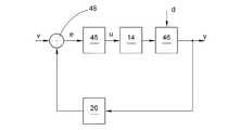
エラーのない正常な巻き取り動作では、糸テンションは各作業ユニット部において閉ループ制御される。この閉ループ制御は、図3においてブロック図を用いて略示されている。この実施例では、糸引張力に対する目標値vがあらかじめ設定される。この目標値は、例えば中央制御ユニット50の傍にいるオペレータにより、1つのロットに対してあらかじめ設定することができ、またバスシステム60により、このロットに属する作業ユニット部2の作業ユニット制御部40に通知することができる。糸引張力の実際値yは、糸引張力センサ20によって測定される。目標値vと実際値yとを比較するため、これらの量の間の差分eを求める。このためにマイナスの符号を有する測定した実際値yおよび目標値vが加算器48に供給される。このようにした求めた差分eは、制御器45に対する入力信号であり、この制御器により、糸テンショナ14に対する調整信号uが供給される。加算器48を有する比較装置および制御器45は、この実施例において作業ユニット制御部40の一部分である。しかしながら基本的には、上記の閉ループ制御部を上記の中央制御ユニットに実現することも可能である。図3のブロック図における糸テンショナ14に後置接続されたブロック46は、制御技術において区間と称される。ここで区間46には上記の作業ユニット部の複数の部分が含まれており、これらの部分が、糸テンショナの影響の下で、走行する糸に所定の糸テンションないしは糸引張力に作用させる。目標値または測定した実際値として、糸引張力の代わりに糸テンションを使用することも可能である。場合によっては上記の糸テンションを糸引張力に換算するかまたはその逆を行わなければならない。
In normal winding operation with no error, the yarn tension is closed-loop controlled in each work unit. This closed loop control is schematically illustrated using a block diagram in FIG. In this embodiment, a target value v for the yarn pulling force is set in advance. This target value can be set in advance for one lot by an operator near the
図4には、上で説明した閉ループ制御の作用が説明されている。ここでは糸テンショナ14に対する調整信号が一方の側に、また糸引張力の目標値vないしは実際値yが他方の側に、時間ないしは紡績コップから巻き取った糸の長さについてプロットされている。ここで前提としたのは一定の巻き取り速度であるため、巻き取られた糸の長さは時間に比例する。さらにここでは定常的な制御偏差のない理想的な閉ループ制御を全体としたため、目標値vと実際値yとは同じである。さらに制御信号uは、糸テンショナによって加えられるテンショナ圧に比例している。一定の糸引張力を維持するため、最初のうちは比較的高いテンショナ圧が必要である。また紡績コップに残っている糸の量が小さければ小さいほど、ないしは巻き取った糸の長さが長ければ長いほど、テンショナ圧を低く調整して一定の糸引張力を維持しなければならない。したがってテンショナ圧が一定の場合、糸引張力は、巻き取った糸の長さに伴って増大することになるのである。
FIG. 4 illustrates the operation of the closed loop control described above. Here, the adjustment signal for the
巻き取り速度は、上で述べたようにコップ移動全体にわたって一定のままである必要はない。上記の糸テンショナが上記の圧力をさらに低減させることができない場合、上記の巻き取り速度を段階的に低減して、糸引張力の閉ループ制御が再び、調整素子としての糸テンショナによって可能になるようにする。図3のブロック図には、外乱量dによる巻き取り速度の変化の影響がシンボリックに表されている。 The winding speed need not remain constant throughout the cup movement as described above. If the above-mentioned yarn tensioner cannot further reduce the above-mentioned pressure, the above-described winding speed is reduced stepwise so that closed-loop control of the yarn tension force is again possible with the yarn tensioner as the adjusting element. To do. In the block diagram of FIG. 3, the influence of the change in the winding speed due to the disturbance amount d is symbolically represented.
正常な巻き取り動作中、糸テンショナ14の調整信号uは、各紡績コップから巻き取られた糸の長さに依存して検出されて記憶される。付加的には都度の巻き取り速度が一緒に記憶される。これらの値は、作業ユニット制御部の記憶装置または中央制御ユニットの記憶装置にネットワークフェイルセーフで記憶することができる。この記憶は、例えばテーブルの形式で行うことができる。この場合、このテーブルにより、巻き取られた糸の長さと、調整信号uおよび巻き取り速度に対する値とが対応付けられる。ここでは巻き取られた糸の長さと、紡績コップに残っている糸の所定の量とが対応する。巻き取られた糸の長さは、例えば、公知のように駆動ローラ26の回転から求めることができる。このために駆動ローラ26の回転を検出してカウンタに記憶する。この場合のこのカウンタは、紡績コップの交換毎にリセットしなければならない。上記の回転数は、巻き取られた糸の長さに比例する。この値は、上記の調整信号のそれぞれの値に直接対応付けることができる。駆動ローラ直径に基づいて糸の長さに換算する必要はない。このようにして求めかつ記憶した上記の調整信号に対する値はすでに、本発明における経験値を表す。これらの値を後続処理することにより、場合によっては固有の経験値を導くことができる。このことを目的として、巻き取った糸の長さに対応する複数の調整信号値の平均値を形成することができる。したがって例えば、作業ユニット部2において巻き取った1つのロットの複数またはすべての紡績コップ9の平均値を求め、テーブルに相応に記憶することができる。1つのロットのすべてまたは複数の作業ユニット部2の平均値を使用することも可能である。このために有利であるのは、まだ行われていない場合、作業ユニット部2において検出した値を中央制御ユニット50に通知することである。この場合にここではこのロットのすべての紡績コップ9の平均値またはこのロットの複数またはすべての巻き取り箇所のそれぞれ最後の紡績コップ9の平均値を求めることができる。つぎにこの平均値は、テーブルに相応に記憶される。ここでは巻き取った糸の長さのそれぞれの値と、上記の調整信号の平均値とが対応付けられる。
During normal winding operation, the adjustment signal u of the
作業ユニット制御部40により、その作業ユニット部2の糸引張力センサ20の故障が確認されると直ちに、該当する作業ユニット部2において糸テンションが閉ループ制御から開ループ制御に自動的にすなわちオペレータによる介入なしに切り換わる。同時に中央制御ユニット50のディスプレイ51に相応するエラー通知が表示される。このような制御が図5に略示されている。ブロック47は記憶装置を表しており、この記憶装置には上で説明した経験値がテーブルの形で記憶されている。テーブルでは、巻き取った糸の長さと、上記の調整信号に対する1つずつの値とが対応付けられている。どの経験値を使用するかに応じて、作業ユニット制御部40または中央制御ユニット50の記憶装置47を対応付けることができる。紡績コップから巻きとった糸の長さと、上記のテーブルとに基づいて求めた調整信号uはつぎに糸テンショナ14に供給される。付加的には巻き取り速度が、上記のテーブルに記憶されている値に設定される。区間46により、糸テンションの実際値yが形成される。上記の糸テンションは閉ループ制御されるのではなく開ループ制御されるのにも拘わらず、この実際値yと、上記の目標値vとは近い。
As soon as a failure of the
1 ワインダ、 2 作業ユニット部、 3 リールおよびボビン搬送システム、 4 コップ供給区間、 5 蓄積区間、 6 横方向搬送区間、 7 ボビン戻し区間、 8 搬送プレート、 9 紡績コップ、 10 巻き取り位置、 11 綾巻きパッケージ、 12 吸引ノズル、 13 スプライス装置、 14 糸テンショナ、 15 糸クリーナ、 16 パラフィン処理装置、 17 糸切断装置、 18 巻き取りフレーム、 19 旋回軸、 20 糸引張力センサ、 21 綾巻きパッケージ搬送装置、 22 下糸センサ、 23 糸捕集ノズル、 24 ワインド装置、 25 把持管、 26 駆動ローラ、 27 空気分岐路、 28 糸綾振り装置、 29 フィンガ型糸ガイド、 30 糸、 32 負圧ビーム、 33 負圧源、 34 空ボビン、 35 接続管部、 36 解放管部、 40 作業ユニット制御部、 45 制御器、 48 加算器、 50 中央制御ユニット、 51 ディスプレイ、 60 バスシステム、 y 実際値、 v 目標値、 e 差分、 u 調整信号
DESCRIPTION OF
Claims (11)
前記糸(30)の走行時に、前記糸のテンションを表す量を測定する1つずつのセンサ(20)と、
前記糸(30)に糸テンションを与える糸テンショナ(14)と、
が配置されており、
前記糸テンションを表す測定量(y)と、前記糸テンションを表す量の目標値(v)と、を比較し、前記比較(e)に依存して、前記糸テンションを調整するために前記糸テンショナ(14)に対する調整信号(u)を生成することによって前記糸テンションを閉ループ制御し、
1つのセンサ(20)の故障を確認した後、前記糸テンションを開ループ制御する方法において、
前記紡績コップ(9)に残っている糸の長さを表す量をそれぞれ検出し、
前記紡績コップ(9)に残っている糸の長さに依存して、閉ループ制御された糸テンションによる巻き取り中に検出した少なくとも1つの調整信号(u)から、前記調整信号(u)に対する経験値を求め、
1つのセンサ(20)が故障した場合、前記糸テンショナ(14)によって糸テンションを開ループ制御するため、前記紡績コップ(9)に残っている糸の長さに依存して、前に求めた前記調整信号(u)に対する経験値を調整信号(u)として使用する、
方法。 A method of operating a winder (1) having a plurality of work unit portions (2) for winding one yarn (30) from a spinning cup (9) into a traverse package (11),
During running of the previous SL yarns (30), a sensor (20) of one of measuring the quantity representative of the yarn tension,
Yarn tensioner which gives the yarn tension before Symbol thread (30) and (14),
Is placed,
Measured quantity representative of the previous SL yarn tension and (y), the target value of the quantity representing the previous SL yarn tension and (v), comparing, in dependence said the comparison (e), to adjust the pre-Symbol yarn tension and closed-loop control the pre-Symbol yarn tension by producing an adjustment signal (u) for the previous SL yarn tensioner (14) to,
After confirming the failure of one sensor (20), in the pre-Symbol yarn tension open loop control to that way,
The amount representing the length of yarn remaining before Symbol spinning cop (9) respectively detected,
Depending on the length of the yarn that the remaining spinning cop (9), at least one adjustment signal has been detected during the winding due to a closed loop control yarn tension (u), experience with the adjustment signal (u) Find the value
If one sensor (20) has failed, for open loop control of the yarn tension by pre-Symbol thread tensioner (14), depending on the length of the yarn that remains before Symbol spinning cop (9), before to use the experience for the obtained pre SL adjustment signal (u) as an adjustment signal (u),
METHODS.
請求項1に記載の方法。 To determine the previous SL experience, to detect the adjustment signals of a plurality of working units part,
The method of claim 1.
請求項1または2に記載の方法。 Using the length of the wound yarn from the previous SL spinning cop (9), as an amount representing the amount of yarn the remaining spinning cop (9),
The method according to claim 1 or 2.
請求項2または3に記載の方法。 One work unit part the previous SL experience values used for sensor (20) is open-loop control before Symbol yarn tension when failure (2), the same work before the sensor (20) fails Obtained from an adjustment signal detected during winding of at least one spinning cup (9) of the unit part,
The method according to claim 2 or 3.
請求項4に記載の方法。 One work unit part the previous SL experience values used for sensor (20) is open-loop control before Symbol yarn tension when failure (2), the work before the sensor (20) fails From the adjustment signal detected during winding of the last spinning cup (9) of the unit part (2),
The method of claim 4.
請求項4に記載の方法。 Before SL experience used to sensor (20) is open-loop control before Symbol yarn tension when failure of one of the working unit section (2) is wound by the working unit section (2) is the average value before Symbol adjustment signal (u) of the plurality of spinning cop (9),
The method of claim 4.
請求項2または3に記載の方法。 One unit of work portion (2) of the sensor (20) before Symbol empirical values used to open-loop control the pre-Symbol yarn tension when has failed, a plurality of working units of the same lot in (2) An average value of a plurality of adjustment signals (u),
The method according to claim 2 or 3.
請求項7に記載の方法。 One work unit section before Symbol empirical values used for sensor (20) is open-loop control before Symbol yarn tension when failure (2), a plurality of working units of the previous SL Lot (2) Is the average value of the plurality of adjustment signals (u) detected when the last spinning cup (9) is wound up,
The method of claim 7.
請求項1から8までのいずれか1項に記載の方法。 Display a failure of the sensor (20),
9. A method according to any one of claims 1-8.
前記紡績コップに残っている糸の長さに依存して、巻き取り速度に対する経験値を検出し、
センサ(20)が故障した場合、前記残った糸の長さに依存して、前もって求めた巻き取り速度に対する前記経験値を使用して前記巻き取り速度を設定する、
請求項1から9までのいずれか1項に記載の方法。 During winding according to a closed loop control yarn tension was adjusted depending of the previous SL winding speed adjustment before Symbol thread tensioner (14),
Depending on the length of the yarn remaining before Symbol spinning cop, to detect the experience value for the take-up speed,
If the sensor (20) has failed, depending on the length of the pre-Symbol remaining yarns, it sets the previous SL winding speed using the previous SL experience for previously determined winding speed,
10. A method according to any one of claims 1-9.
前記糸(30)の走行時に、前記糸のテンションを表す量を測定する1つずつのセンサ(20)と、
前記糸(30)に糸テンションを与える糸テンショナ(14)と、
が配置されており、
前記糸テンションを閉ループ制御するための制御手段(40,50)が設けられており、
前記制御手段は、前記糸テンションを表す測定量(y)と、前記糸テンションを表す量の目標値(v)と、を比較し、前記比較(e)に依存して、前記糸テンションを調整するために糸テンショナ(14)に対する調整信号(u)を生成するために構成されており、
前記制御手段(40,50)は、前記センサ(20)が故障した場合に前記糸テンションを開ループ制御するように構成されているワインダにおいて、
前記制御手段(40,50)は、
前記紡績コップに残っている糸の長さを表す量を検出するため、
前記紡績コップに残る糸の長さを表す量に依存して、閉ループ制御された糸テンションによる巻き取り中に検出した少なくとも1つの調整信号(u)から、前記調整信号(u)に対する経験値を求めるため、および
センサ(20)が故障した場合には、前記紡績コップ(9)に残っている糸の長さを表す量に依存して、前記経験値の少なくとも一部を調整信号(u)として使用して、前記糸テンショナ(14)に対する糸テンションを開ループ制御するように構成されている、
請求項1から10までのいずれか1項に記載の方法を実施するワインダ。 A winder having a plurality of work unit portions (2) configured to wind the yarn (30) from the spinning cup (9) into the traverse package (11),
During running of the previous SL yarns (30), a sensor (20) of one of measuring the quantity representative of the yarn tension,
Yarn tensioner which gives the yarn tension before Symbol thread (30) and (14),
Is placed,
Control means (40, 50) is provided for closed-loop control the pre-Symbol yarn tension,
Said control means measuring quantity representing the previous SL yarn tension and (y), the target value of the quantity representing the previous SL yarn tension and (v), comparing, in dependence said the comparison (e), before Symbol yarn Configured to generate an adjustment signal (u) for the thread tensioner (14) to adjust the tension;
Before SL control means (40, 50), prior Symbol sensor (20) is Ruwa inductor consists of pre Symbol yarn tension to open loop control in case of failure,
Before Symbol control means (40, 50) is,
For detecting the amount representing the length of yarn remaining before Symbol cop,
Depending on the amount representing the length of the yarn remaining on the spinning cop, at least one adjustment signal has been detected during the winding due to a closed loop control yarn tension (u), the experience value for said adjustment signal (u) Request for, and when the sensor (20) fails, before SL depending on the amount representing the length of the yarn remaining on the spinning cop (9), at least a portion of the adjustment signal before SL experience ( use as u), and is configured to thread tension for the previous SL yarn tensioner (14) so as to open loop control,
Winder for carrying out the method according to any one of the preceding claims.
Applications Claiming Priority (2)
| Application Number | Priority Date | Filing Date | Title |
|---|---|---|---|
| DE102010056116.9 | 2010-12-23 | ||
| DE102010056116A DE102010056116A1 (en) | 2010-12-23 | 2010-12-23 | Method for operating a winding machine and winding machine |
Publications (3)
| Publication Number | Publication Date |
|---|---|
| JP2012131643A JP2012131643A (en) | 2012-07-12 |
| JP2012131643A5 JP2012131643A5 (en) | 2014-10-16 |
| JP5916374B2 true JP5916374B2 (en) | 2016-05-11 |
Family
ID=45062808
Family Applications (1)
| Application Number | Title | Priority Date | Filing Date |
|---|---|---|---|
| JP2011283731A Active JP5916374B2 (en) | 2010-12-23 | 2011-12-26 | Method for operating a winder and winder |
Country Status (4)
| Country | Link |
|---|---|
| EP (1) | EP2468670B1 (en) |
| JP (1) | JP5916374B2 (en) |
| CN (1) | CN102530646B (en) |
| DE (1) | DE102010056116A1 (en) |
Families Citing this family (10)
| Publication number | Priority date | Publication date | Assignee | Title |
|---|---|---|---|---|
| DE102012007683A1 (en) * | 2012-04-17 | 2013-10-17 | Oerlikon Textile Gmbh & Co. Kg | Method for operating a winding machine and winding machine |
| CN103451790B (en) * | 2013-08-22 | 2016-03-30 | 浙江康立自控科技有限公司 | Yield statistic device of textile machine |
| DE102013021316A1 (en) * | 2013-12-16 | 2015-06-18 | Saurer Germany Gmbh & Co. Kg | Method for operating a winding machine and winding machine |
| DE102015008166A1 (en) * | 2015-06-25 | 2016-12-29 | Saurer Germany Gmbh & Co. Kg | Method and device for optimizing the density of cheeses produced on the work stations of a cheese-winder |
| DE102016121667A1 (en) | 2016-11-11 | 2018-05-17 | Saurer Germany Gmbh & Co. Kg | Method for operating a winding unit and winding machine |
| US11305960B2 (en) * | 2017-06-07 | 2022-04-19 | Oerlikon Textile Gmbh & Co. Kg | Method and device for monitoring a yarn tension of a running yarn |
| IT201900001195A1 (en) * | 2019-01-28 | 2020-07-28 | Savio Macch Tessili Spa | SPINNING APPARATUS, IN PARTICULAR WITH AIR, WITH CONTINUOUS REGULATION OF A YARN ACCUMULATION SYSTEM AND RELATIVE METHOD OF CONTINUOUS REGULATION OF A YARN ACCUMULATION SYSTEM IN A SPINNING APPARATUS |
| EP3828325A1 (en) * | 2019-11-29 | 2021-06-02 | Saurer Intelligent Technology AG | Spinning station and air spinning station comprising such a spinning station and process to determin a yarn strength defect |
| DE102020131278A1 (en) * | 2020-11-26 | 2022-06-02 | Saurer Spinning Solutions Gmbh & Co. Kg | Process and preparation device for preparing spinning cops |
| CN113682891B (en) * | 2021-09-07 | 2023-05-19 | 巨石集团有限公司 | Single-head double-split cake winding machine and cake winding method thereof |
Family Cites Families (10)
| Publication number | Priority date | Publication date | Assignee | Title |
|---|---|---|---|---|
| IT1218170B (en) * | 1986-10-11 | 1990-04-12 | Murata Machinery Ltd | PROCEDURE FOR WINDING WIRE IN AUTOMATIC WINDING MACHINE AND RELATED CONTROL DEVICE |
| DE3733597A1 (en) | 1987-10-05 | 1989-04-20 | Schlafhorst & Co W | Process and device for the rewinding of cops |
| DE3939789C2 (en) * | 1989-12-01 | 1999-02-11 | Schlafhorst & Co W | Method and device for operating an automatic textile machine |
| JP2936917B2 (en) * | 1992-10-16 | 1999-08-23 | 村田機械株式会社 | Automatic winder tension control device |
| JP3564817B2 (en) * | 1995-09-14 | 2004-09-15 | 村田機械株式会社 | Winder |
| ITMI20051325A1 (en) * | 2005-07-12 | 2007-01-13 | Btsr Int Spa | METHOD AND DEVICE TO ENSURE THE SUPPLY OF A CONSTANT VOLTAGE THREAD WITH A DOUBLE RING ADJUSTMENT TO A TEXTILE MACHINE |
| JP2009024097A (en) | 2007-07-20 | 2009-02-05 | Nisshinbo Ind Inc | Method for producing carbodiimide compound |
| JP2009242096A (en) | 2008-03-31 | 2009-10-22 | Murata Mach Ltd | Automatic winder |
| JP2009242097A (en) * | 2008-03-31 | 2009-10-22 | Murata Mach Ltd | Automatic winder and package winding method for automatic winder |
| CN201425533Y (en) * | 2009-05-26 | 2010-03-17 | 浙江双箭橡胶股份有限公司 | Tension detection device |
-
2010
- 2010-12-23 DE DE102010056116A patent/DE102010056116A1/en not_active Withdrawn
-
2011
- 2011-11-23 EP EP20110009261 patent/EP2468670B1/en not_active Not-in-force
- 2011-12-20 CN CN201110462104.0A patent/CN102530646B/en not_active Expired - Fee Related
- 2011-12-26 JP JP2011283731A patent/JP5916374B2/en active Active
Also Published As
| Publication number | Publication date |
|---|---|
| CN102530646A (en) | 2012-07-04 |
| EP2468670B1 (en) | 2014-08-06 |
| EP2468670A3 (en) | 2013-08-21 |
| EP2468670A2 (en) | 2012-06-27 |
| CN102530646B (en) | 2016-03-30 |
| JP2012131643A (en) | 2012-07-12 |
| DE102010056116A1 (en) | 2012-06-28 |
Similar Documents
| Publication | Publication Date | Title |
|---|---|---|
| JP5916374B2 (en) | Method for operating a winder and winder | |
| JP6176952B2 (en) | How to optimize the winding speed of the working part of an autowinder | |
| JP5001849B2 (en) | Method and apparatus for operating a work site of a textile machine producing a twill package | |
| WO2010134294A1 (en) | Yarn winding device and alarm threshold value determination method for detection of rotational faults in a package | |
| CN101268001B (en) | Method for operating a workstation of a textile machine that produces crosswound bobbins | |
| EP3009387B1 (en) | Yarn winding device and package decelerating method | |
| EP2159180B1 (en) | Yarn winding device and automatic winder | |
| EP2808283B1 (en) | Yarn winding machine | |
| JP2017014015A (en) | Method and apparatus for optimizing density of cross winding package manufactured in working unit for cross winding automatic winder | |
| JP6242670B2 (en) | Method for controlling acceleration of package drive roller | |
| JP2009227412A (en) | Yarn winder and yarn winding method | |
| US6340129B1 (en) | Method for operating a workstation of a cheese-producing textile machine | |
| JP6738184B2 (en) | Method and system for operating a complex system consisting of at least one ring spinning machine and at least one winder | |
| JP7346200B2 (en) | Method and apparatus for detecting yarn loops in a working unit of a textile machine producing wound packages | |
| EP2484618B1 (en) | Yarn winder | |
| JP2010042904A (en) | Yarn winding machine | |
| JP6120654B2 (en) | Method for operating a winder and winder | |
| EP2962973B1 (en) | Yarn winding device | |
| JP2016194187A (en) | Method for operating composite system comprising at least one ring spinning machine and at least one winding machine, and composite system | |
| JP2019031399A (en) | Device for clearing removal of yarn defects from yarn | |
| EP2690044B1 (en) | Yarn winding device | |
| CN108069290B (en) | For operating the method and coil winding machine of winder unit | |
| JP6453717B2 (en) | Textile machine provided with winding device | |
| JP2014108895A (en) | Acceleration control method of package driving roller | |
| JP2016132574A (en) | Method and device for evaluating yarn splicing part |
Legal Events
| Date | Code | Title | Description |
|---|---|---|---|
| A711 | Notification of change in applicant |
Free format text: JAPANESE INTERMEDIATE CODE: A711 Effective date: 20130819 |
|
| A521 | Written amendment |
Free format text: JAPANESE INTERMEDIATE CODE: A523 Effective date: 20140902 |
|
| A621 | Written request for application examination |
Free format text: JAPANESE INTERMEDIATE CODE: A621 Effective date: 20140902 |
|
| A977 | Report on retrieval |
Free format text: JAPANESE INTERMEDIATE CODE: A971007 Effective date: 20150819 |
|
| A131 | Notification of reasons for refusal |
Free format text: JAPANESE INTERMEDIATE CODE: A131 Effective date: 20150824 |
|
| A601 | Written request for extension of time |
Free format text: JAPANESE INTERMEDIATE CODE: A601 Effective date: 20151124 |
|
| A521 | Written amendment |
Free format text: JAPANESE INTERMEDIATE CODE: A523 Effective date: 20151209 |
|
| TRDD | Decision of grant or rejection written | ||
| A01 | Written decision to grant a patent or to grant a registration (utility model) |
Free format text: JAPANESE INTERMEDIATE CODE: A01 Effective date: 20160307 |
|
| A61 | First payment of annual fees (during grant procedure) |
Free format text: JAPANESE INTERMEDIATE CODE: A61 Effective date: 20160405 |
|
| R150 | Certificate of patent or registration of utility model |
Ref document number: 5916374 Country of ref document: JP Free format text: JAPANESE INTERMEDIATE CODE: R150 |
|
| R250 | Receipt of annual fees |
Free format text: JAPANESE INTERMEDIATE CODE: R250 |