JP5911336B2 - Small vehicle - Google Patents

Small vehicle Download PDF

Info

Publication number
JP5911336B2
JP5911336B2 JP2012040551A JP2012040551A JP5911336B2 JP 5911336 B2 JP5911336 B2 JP 5911336B2 JP 2012040551 A JP2012040551 A JP 2012040551A JP 2012040551 A JP2012040551 A JP 2012040551A JP 5911336 B2 JP5911336 B2 JP 5911336B2
Authority
JP
Japan
Prior art keywords
protective member
catalyst chamber
vehicle body
vehicle
attached
Prior art date
Legal status (The legal status is an assumption and is not a legal conclusion. Google has not performed a legal analysis and makes no representation as to the accuracy of the status listed.)
Active
Application number
JP2012040551A
Other languages
Japanese (ja)
Other versions
JP2013173498A (en
JP2013173498A5 (en
Inventor
正也 矢▲崎▼
正也 矢▲崎▼
栗原 博
博 栗原
良孝 ▲羽▼山
良孝 ▲羽▼山
崇輝 笠井
崇輝 笠井
Current Assignee (The listed assignees may be inaccurate. Google has not performed a legal analysis and makes no representation or warranty as to the accuracy of the list.)
Honda Motor Co Ltd
Original Assignee
Honda Motor Co Ltd
Priority date (The priority date is an assumption and is not a legal conclusion. Google has not performed a legal analysis and makes no representation as to the accuracy of the date listed.)
Filing date
Publication date
Application filed by Honda Motor Co Ltd filed Critical Honda Motor Co Ltd
Priority to JP2012040551A priority Critical patent/JP5911336B2/en
Priority to DE102012221963A priority patent/DE102012221963A1/en
Priority to IT001151A priority patent/ITTO20121151A1/en
Priority to US13/765,202 priority patent/US9016427B2/en
Priority to BR102013004334-6A priority patent/BR102013004334B1/en
Publication of JP2013173498A publication Critical patent/JP2013173498A/en
Publication of JP2013173498A5 publication Critical patent/JP2013173498A5/ja
Application granted granted Critical
Publication of JP5911336B2 publication Critical patent/JP5911336B2/en
Active legal-status Critical Current
Anticipated expiration legal-status Critical

Links

Images

Classifications

    • BPERFORMING OPERATIONS; TRANSPORTING
    • B62LAND VEHICLES FOR TRAVELLING OTHERWISE THAN ON RAILS
    • B62KCYCLES; CYCLE FRAMES; CYCLE STEERING DEVICES; RIDER-OPERATED TERMINAL CONTROLS SPECIALLY ADAPTED FOR CYCLES; CYCLE AXLE SUSPENSIONS; CYCLE SIDE-CARS, FORECARS, OR THE LIKE
    • B62K11/00Motorcycles, engine-assisted cycles or motor scooters with one or two wheels
    • BPERFORMING OPERATIONS; TRANSPORTING
    • B60VEHICLES IN GENERAL
    • B60RVEHICLES, VEHICLE FITTINGS, OR VEHICLE PARTS, NOT OTHERWISE PROVIDED FOR
    • B60R13/00Elements for body-finishing, identifying, or decorating; Arrangements or adaptations for advertising purposes
    • B60R13/08Insulating elements, e.g. for sound insulation
    • B60R13/0876Insulating elements, e.g. for sound insulation for mounting around heat sources, e.g. exhaust pipes
    • BPERFORMING OPERATIONS; TRANSPORTING
    • B62LAND VEHICLES FOR TRAVELLING OTHERWISE THAN ON RAILS
    • B62JCYCLE SADDLES OR SEATS; AUXILIARY DEVICES OR ACCESSORIES SPECIALLY ADAPTED TO CYCLES AND NOT OTHERWISE PROVIDED FOR, e.g. ARTICLE CARRIERS OR CYCLE PROTECTORS
    • B62J23/00Other protectors specially adapted for cycles

Landscapes

  • Engineering & Computer Science (AREA)
  • Mechanical Engineering (AREA)
  • Physics & Mathematics (AREA)
  • Acoustics & Sound (AREA)
  • Exhaust Silencers (AREA)

Description

本発明は、排気装置を覆う車体カバーが備えられている小型車両の改良に関する。   The present invention relates to an improvement of a small vehicle provided with a vehicle body cover that covers an exhaust device.

排気ガスを浄化する排気装置を覆う車体カバーが備えられている小型車両が知られている(例えば、特許文献1(図1、図2、図4)参照。)。   There is known a small vehicle provided with a vehicle body cover that covers an exhaust device that purifies exhaust gas (see, for example, Patent Document 1 (FIGS. 1, 2, and 4)).

特許文献1の図1に示すように、エンジン(40)(括弧付き数字は、特許文献1記載の符号を示す。要素名は一部変更した。以下同じ。)の下方に、排気装置(70)が配置され、この排気装置(70)の車幅方向外方に、ロアカウル(121)が配置される。ロアカウル(121)(以下、保護部材(121)と言う。)は、排気装置(70)を覆っている。   As shown in FIG. 1 of Patent Document 1, an exhaust device (70) is provided below the engine (40) (the numbers in parentheses indicate the reference numerals described in Patent Document 1. Some element names have been changed. The same applies hereinafter). ) And a lower cowl (121) is arranged outside the exhaust device (70) in the vehicle width direction. The lower cowl (121) (hereinafter referred to as a protective member (121)) covers the exhaust device (70).

特許文献1の図2及び図4に示すように、車体フレーム(20)へ止めねじ(124、124)で締結される保護部材(121)の取付部は、保護部材(121)の上部が車体フレーム(20)に達するまで車両内方へ延びている。保護部材(121)は、車両内方まで延びているため、保護部材(121)の形状自由度に制約があった。   As shown in FIGS. 2 and 4 of Patent Document 1, the mounting portion of the protective member (121) fastened to the vehicle body frame (20) with the set screws (124, 124) is the upper portion of the protective member (121). The vehicle extends inward until it reaches the frame (20). Since the protection member (121) extends to the inside of the vehicle, the shape freedom of the protection member (121) is limited.

一方、保護部材(121)の上方で車体を覆うミッドカウル(111)は、排気装置を覆う必要がないため、ミッドカウル(111)の形状自由度は確保される。しかし、保護部材(121)とミッドカウル(111)との間で滑らかな外観面を構成していない。保護部材(121)との間で滑らかな外観面を構成するためには、ミッドカウル(111)を境界部を保護部材(121)の形状に合わせる必要があり形状自由度に制約が生ずる。
そこで、車体カバーと保護部材の双方の形状自由度を高めつつ車両の外観性を確保する技術が望まれる。
On the other hand, since the mid cowl (111) that covers the vehicle body above the protective member (121) does not need to cover the exhaust device, the mid cowl (111) has a high degree of freedom. However, a smooth appearance surface is not formed between the protective member (121) and the mid cowl (111). In order to form a smooth appearance surface with the protective member (121), it is necessary to match the boundary portion of the mid cowl (111) with the shape of the protective member (121), and the degree of freedom in shape is limited.
Therefore, a technique for ensuring the appearance of the vehicle while increasing the degree of freedom of shape of both the vehicle body cover and the protection member is desired.

特許第3727641号公報Japanese Patent No. 3727641

本発明は、排気装置を覆う保護部材を備えた小型車両において、車体カバーと保護部材双方の形状自由度を高めつつ車両の外観性を確保する技術を提供することを課題とする。   An object of the present invention is to provide a technique for ensuring the appearance of a vehicle while increasing the degree of freedom of shape of both the body cover and the protection member in a small vehicle including a protection member that covers the exhaust device.

請求項1に係る発明は、内燃機関と、この内燃機関から下方へ延び内燃機関から排出される排気ガスを浄化若しくは消音する排気装置と、内燃機関の少なくとも側方を覆い車両の外面を構成する車体カバーとが備えられている小型車両において、車体カバーと連続する連続面を有し排気装置の側方を覆う保護部材が備えられ、この保護部材と車体カバーとが協働して車両の外面を構成するようにし、保護部材は、排気装置に取付けられていることを特徴とする。   The invention according to claim 1 comprises an internal combustion engine, an exhaust device that extends downward from the internal combustion engine and purifies or silences exhaust gas discharged from the internal combustion engine, and covers at least the sides of the internal combustion engine to constitute the outer surface of the vehicle. In a small vehicle provided with a vehicle body cover, a protective member that has a continuous surface continuous with the vehicle body cover and covers the side of the exhaust device is provided, and the protective member and the vehicle body cover cooperate to provide an outer surface of the vehicle. The protective member is attached to the exhaust device.

加えて、請求項に係る発明では、車体カバーは樹脂により形成され、保護部材は金属で成形されると共に弾性部材を介して排気装置に取付けられることを特徴とする。 In addition, the invention according to claim 1 is characterized in that the vehicle body cover is made of resin, and the protective member is formed of metal and attached to the exhaust device via an elastic member.

加えて、請求項に係る発明では、小型車両は、更に、車体フレームを含み、この車体フレームに、車体カバーが取付けられていることを特徴とする。 In addition, in the invention according to claim 1 , the small vehicle further includes a vehicle body frame, and a vehicle body cover is attached to the vehicle body frame.

加えて、請求項に係る発明では、排気装置は、内部に触媒を包含した触媒室を有し、この触媒室の上部及び下部で保護部材が保持されることを特徴とする。 In addition, the invention according to claim 1 is characterized in that the exhaust device has a catalyst chamber containing a catalyst therein, and a protective member is held at the upper and lower portions of the catalyst chamber.

加えて、請求項に係る発明では、排気装置は、触媒室の前端部に接続される上流排気管と、触媒室の後端部に接続される下流排気管とを有し、さらに、これらの上流排気管と下流排気管のうちのいずれか一方に保持されることを特徴とする。 In addition, in the invention according to claim 1 , the exhaust device includes an upstream exhaust pipe connected to the front end portion of the catalyst chamber, and a downstream exhaust pipe connected to the rear end portion of the catalyst chamber, and these It is characterized by being held in either one of the upstream exhaust pipe and the downstream exhaust pipe.

請求項に係る発明では、車両側面視で、保護部材は、触媒室の全体を覆うように略三角形状に形成されることを特徴とする。 The invention according to claim 2 is characterized in that the protective member is formed in a substantially triangular shape so as to cover the entire catalyst chamber in a side view of the vehicle.

請求項に係る発明では、保護部材は、平板状に形成されると共に、一部に凹部を形成したことを特徴とする。 The invention according to claim 3 is characterized in that the protective member is formed in a flat plate shape, and a concave portion is formed in a part thereof.

請求項に係る発明は、触媒室に、センサ部品が取付けられ、保護部材は、センサ部品を触媒室と共に覆うように形成されることを特徴とする。 The invention according to claim 4 is characterized in that the sensor component is attached to the catalyst chamber, and the protective member is formed so as to cover the sensor component together with the catalyst chamber.

請求項1に係る発明では、排気装置の側方を覆う保護部材は、車体カバーと連続する連続面を有する。保護部材に車体カバーと連続する連続面をもたせたので、保護部材の面と車体カバーの面を滑らかにつなげることができる。車体カバーに排気装置を覆い隠すような形状をもたせる必要がなく、車体カバーの形状自由度を高めることができる。   In the invention which concerns on Claim 1, the protection member which covers the side of an exhaust apparatus has a continuous surface continuous with a vehicle body cover. Since the protective member has a continuous surface continuous with the vehicle body cover, the surface of the protective member and the surface of the vehicle body cover can be smoothly connected. It is not necessary to give the vehicle body cover a shape that covers the exhaust device, and the degree of freedom of shape of the vehicle body cover can be increased.

また、保護部材は、車体フレームに較べて近い側に位置する排気装置に取付けられる。車体フレームに較べ、保護部材の近傍に配置される排気装置に、保護部材を取付けたので、保護部材の一部を延ばす必要はない。結果、保護部材の形状自由度を高めることができる。結果、本発明によれば、車体カバーと保護部材双方の形状自由度を高めながら、車両の外観性を確保することができる。   Further, the protective member is attached to the exhaust device located on the side closer to the body frame. Compared to the vehicle body frame, since the protective member is attached to the exhaust device disposed in the vicinity of the protective member, it is not necessary to extend a part of the protective member. As a result, the degree of freedom of shape of the protective member can be increased. As a result, according to the present invention, it is possible to ensure the appearance of the vehicle while increasing the degree of freedom of shape of both the vehicle body cover and the protective member.

加えて、請求項に係る発明では、保護部材は金属で成形され、弾性部材を介して排気装置に取付けられる。保護部材と排気装置との間に介在された弾性部材によって、排気装置から弾性部材に振動が伝わり難くなり、保護部材に排気装置に対する共振現象が起こり難くなる。 In addition, in the invention according to claim 1 , the protection member is formed of metal and is attached to the exhaust device via the elastic member. The elastic member interposed between the protective member and the exhaust device makes it difficult for vibration to be transmitted from the exhaust device to the elastic member, and the resonance phenomenon of the protective member with respect to the exhaust device hardly occurs.

加えて、請求項に係る発明では、車体フレームに車体カバーが取付けられ、排気装置に保護部材が弾性部材を介して取付けられている。車体カバーと保護部材とで支持部材が異なると、車両に生ずる振動等により、車体カバーと保護部材の間の合わせ部に隙間等が生ずる可能性がある。 In addition, in the invention according to claim 1 , the vehicle body cover is attached to the vehicle body frame, and the protection member is attached to the exhaust device via the elastic member. If the support member is different between the vehicle body cover and the protection member, there is a possibility that a gap or the like is generated at a joint portion between the vehicle body cover and the protection member due to vibrations generated in the vehicle.

この点、本発明では、保護部材が弾性部材を介して排気装置に取付けられているので、保護部材の微少移動が許容され、車体カバーと保護部材の間の合わせ部に隙間等を生じ難くできる。   In this respect, in the present invention, since the protective member is attached to the exhaust device via the elastic member, a slight movement of the protective member is allowed, and a gap or the like can hardly be generated at the joint portion between the vehicle body cover and the protective member. .

加えて、請求項に係る発明では、排気装置は触媒室を有し、この触媒室の上部及び下部で保護部材が保持される。上下2カ所で保護部材が保持されるので、上下振動に対する保護部材の取付剛性を高めることができる。 In addition, in the invention according to claim 1 , the exhaust device has a catalyst chamber, and the protective member is held at the upper and lower portions of the catalyst chamber. Since the protective member is held at two upper and lower portions, the mounting rigidity of the protective member against vertical vibration can be increased.

加えて、請求項に係る発明では、保護部材は、触媒室の上部及び下部で保持される上に、上流排気管又は下流排気管に保持される。保護部材にかかる上下方向の振動に加え、保護部材の前部又は後部が保持されるので、旋回時の車幅方向振動(振れ)に対しても保護部材の取付剛性を高めることができる。 In addition, in the invention according to claim 1 , the protective member is held by the upper and lower portions of the catalyst chamber and is also held by the upstream exhaust pipe or the downstream exhaust pipe. Since the front part or the rear part of the protective member is held in addition to the vibration in the vertical direction applied to the protective member, the mounting rigidity of the protective member can be increased even in the vehicle width direction vibration (vibration) during turning.

請求項に係る発明では、保護部材は、触媒室の全体を覆うように略三角形状に形成される。略三角形状の保護部材の中央部に触媒室を配置し、略三角形状の保護部材の頂点に近い位置にて触媒室を保持させるようにした。略三角形状の保護部材によって、触媒室全体が覆われると共に、保護部材を触媒室に確実に支持させることができる。 In the invention which concerns on Claim 2 , a protection member is formed in a substantially triangular shape so that the whole catalyst chamber may be covered. A catalyst chamber is arranged in the center of the substantially triangular protective member, and the catalyst chamber is held at a position close to the apex of the substantially triangular protective member. The entire catalyst chamber is covered by the substantially triangular protective member, and the protective member can be reliably supported by the catalyst chamber.

請求項に係る発明では、保護部材は、平板状に形成されると共に、一部に凹部を形成した。この凹部により保護部材の剛性が高められる。保護部材の剛性向上によって、触媒室との共振を一層抑制することができる。 In the invention which concerns on Claim 3 , while forming the protection member in flat form, the recessed part was formed in a part. The rigidity of the protective member is enhanced by the recess. By improving the rigidity of the protective member, resonance with the catalyst chamber can be further suppressed.

請求項に係る発明では、触媒室に、センサ部品が取付けられ、センサ部品を触媒室と共に覆うように保護部材を形成した。すなわち、保護部材で触媒室とセンサ部品とを覆うようにした。別個にセンサ部品を覆う専用部品は不要になるため、部品点数の増加を抑制することができる。 In the invention according to claim 4 , the sensor component is attached to the catalyst chamber, and the protective member is formed so as to cover the sensor component together with the catalyst chamber. That is, the protection chamber covers the catalyst chamber and the sensor component. Since a dedicated component that separately covers the sensor component is not required, an increase in the number of components can be suppressed.

本発明に係る自動二輪車の右側面図である。1 is a right side view of a motorcycle according to the present invention. 図1の要部拡大図である。It is a principal part enlarged view of FIG. エンジンから延びる排気装置の正面図である。It is a front view of the exhaust device extended from an engine. 保護部材の取付構造を説明する図である。It is a figure explaining the attachment structure of a protection member. 触媒室を三角状の保護部材で覆うことを説明する側面図である。It is a side view explaining covering a catalyst chamber with a triangular-shaped protection member. 保護部材を車幅方向内方から見た側面図である。It is the side view which looked at the protection member from the vehicle width direction inner side. 排気装置に保護部材と化粧板を取付けることを説明する分解斜視図である。It is a disassembled perspective view explaining attaching a protection member and a decorative board to an exhaust apparatus. 図2の8−8線断面図である。FIG. 8 is a cross-sectional view taken along line 8-8 in FIG. 2. 図2の9−9線断面図である。FIG. 9 is a sectional view taken along line 9-9 in FIG. 2. 図9の10部拡大図である。FIG. 10 is an enlarged view of 10 parts in FIG. 9. 図2の11−11線断面図である。FIG. 11 is a cross-sectional view taken along line 11-11 in FIG. 2. 図11の上部材支持部の斜視図である。It is a perspective view of the upper member support part of FIG. 図2の13−13線断面図である。FIG. 13 is a cross-sectional view taken along line 13-13 in FIG. 2. 触媒室へ流れる排気ガスの流れを説明する図である。It is a figure explaining the flow of the exhaust gas which flows into a catalyst chamber. 図14の別実施例図である。It is another Example figure of FIG. 消音器の断面図である。It is sectional drawing of a silencer. 図16の17−17線断面図である。FIG. 17 is a cross-sectional view taken along line 17-17 in FIG. 16. 図16の18−18線断面図である。FIG. 18 is a cross-sectional view taken along line 18-18 in FIG. 16. 消音器内遮熱板の取付位置を説明する分解斜視図である。It is a disassembled perspective view explaining the attachment position of the heat shield in a silencer. 消音器内遮熱板の表面形状を説明する図である。It is a figure explaining the surface shape of the heat shield in a silencer. 実施例及び比較例に係る消音器の作用説明図である。It is operation | movement explanatory drawing of the silencer which concerns on an Example and a comparative example. 消音器の一部を覆う化粧カバーの支持部を説明する図である。It is a figure explaining the support part of the decorative cover which covers a part of silencer. 実施例及び比較例に係る車体カバーの作用説明図である。It is operation | movement explanatory drawing of the vehicle body cover which concerns on an Example and a comparative example.

以下、本発明の実施の形態について、詳細に説明する。図中及び実施例において、「上」、「下」、「前」、「後」、「左」、「右」は、各々、自動二輪車に乗車する運転者から見た方向を示す。   Hereinafter, embodiments of the present invention will be described in detail. In the drawings and examples, “up”, “down”, “front”, “rear”, “left”, and “right” respectively indicate directions viewed from the driver who rides the motorcycle.

先ず、本発明の実施例を図面に基づいて説明する。
図1に示すように、自動二輪車10は、車体フレーム11と、この車体フレーム11に懸架される内燃機関としてのエンジン12と、車体フレーム前端のヘッドパイプ21に回動自在に取付けられる前輪操舵部14と、車体フレーム11のピボットフレーム23に揺動自在に取付けられる後輪懸架部2と、エンジン12の上方にて車体フレーム11に載置される燃料タンク31と、この燃料タンク31の後方にて車体フレーム11に載置され乗員が座るシート32とを主要素とする小型車両である。
First, an embodiment of the present invention will be described with reference to the drawings.
As shown in FIG. 1, a motorcycle 10 includes a vehicle body frame 11, an engine 12 as an internal combustion engine suspended from the vehicle body frame 11, and a front wheel steering unit rotatably attached to a head pipe 21 at the front end of the vehicle body frame. 14, a wheel suspension unit 2 4 after mounted swingably pivot frame 23 of the vehicle body frame 11, a fuel tank 31 which is mounted on the body frame 11 at the upper side of the engine 12, behind the fuel tank 31 Is a small vehicle having as its main element a seat 32 placed on the body frame 11 and seated by an occupant.

前輪操舵部14は、操舵軸15と、この操舵軸15の上部に取付けられる操舵ハンドル19と、操舵軸15から下方に延びているフロントフォーク16と、このフロントフォーク16の下端に車幅方向に渡される前輪車軸17と、この前輪車軸17に回転自在に取付けられる前輪18とからなる。   The front wheel steering unit 14 includes a steering shaft 15, a steering handle 19 attached to the upper portion of the steering shaft 15, a front fork 16 extending downward from the steering shaft 15, and a lower end of the front fork 16 in the vehicle width direction. It consists of a front wheel axle 17 to be delivered and a front wheel 18 which is rotatably attached to the front wheel axle 17.

後輪懸架部2は、車体フレーム11のピボットフレーム23に車幅方向に渡されるピボット軸25と、このピボット軸25から車両後方に延びているスイングアーム26と、このスイングアーム26の後端に渡される後輪車軸27と、この後輪車軸27に取付けられる後輪28と、スイングアーム26と車体フレーム11の間に渡される図示せぬクッションユニットとからなる。 Rear wheel suspension unit 2 4, the pivot shaft 25 to be passed to the pivot frame 23 of the vehicle body frame 11 in the vehicle width direction, a swing arm 26 extending from the pivot shaft 25 to the vehicle rear, the rear end of the swing arm 26 A rear wheel axle 27 passed to the rear wheel axle 27, a rear wheel 28 attached to the rear wheel axle 27, and a cushion unit (not shown) delivered between the swing arm 26 and the vehicle body frame 11.

次に、車体カバー等について説明する。
車体フレーム11の前部は、樹脂製のフロントカウル41で覆われ、燃料タンク31の下方からエンジン12の下方にかけて及びシート32の下方前部は、樹脂製のミッドカウル42で覆われ、このミッドカウル42に連続してシート32の下方後部は、リヤカウル43で覆われる。フロントカウル41の前端にヘッドライト33が装着されている。前輪18の上方にてフロントフォーク16に前輪18の泥をよけるフロントフェンダ45が取付けられ、車体フレーム11の後端に後輪28の泥をよけるリヤフェンダ46が取付けられている。車体フレーム11に、乗員のうちの運転者が足を置く運転者用ステップ47、47(手前側の符号47のみ示す。)が取付けられ、この運転者用ステップ47、47の後方にて車体フレーム11に、乗員のうちの同乗者が足を置く同乗者用ステップ48、48(手前側の符号48のみ示す。)が同乗者ステップステー49、49(手前側の符号49のみ示す。)を介して取付けられている。
Next, the vehicle body cover and the like will be described.
The front portion of the vehicle body frame 11 is covered with a resin front cowl 41, and the lower front portion of the seat 32 is covered with a resin mid cowl 42 from the lower side of the fuel tank 31 to the lower side of the engine 12. A lower rear portion of the seat 32 that is continuous with the cowl 42 is covered with a rear cowl 43. A headlight 33 is attached to the front end of the front cowl 41. A front fender 45 for preventing mud of the front wheel 18 is attached to the front fork 16 above the front wheel 18, and a rear fender 46 for preventing mud of the rear wheel 28 is attached to the rear end of the vehicle body frame 11. Driver steps 47 and 47 (only the reference numeral 47 on the near side is shown) on which the driver of the occupant puts his / her foot is attached to the vehicle body frame 11, and the vehicle body frame is placed behind the driver steps 47 and 47. 11, passenger steps 48 and 48 (only the reference numeral 48 on the front side) on which the passenger of the passenger puts his / her feet pass through the passenger step stays 49 and 49 (only the reference numeral 49 on the front side is shown). Installed.

エンジン12は、クランク軸が車幅方向に延びている4サイクル2気筒エンジンである。エンジン12は、クランクケース51と、このクランクケース51から車両斜め前上方に延びているシリンダ部52とを含み、シリンダ部52の後壁53に吸気装置60が取付けられ、シリンダ部52の前壁54に排気装置の排気管91が接続されている。   The engine 12 is a four-cycle two-cylinder engine having a crankshaft extending in the vehicle width direction. The engine 12 includes a crankcase 51 and a cylinder portion 52 that extends obliquely upward and forward from the crankcase 51. An intake device 60 is attached to the rear wall 53 of the cylinder portion 52, and the front wall of the cylinder portion 52 is An exhaust pipe 91 of the exhaust device is connected to 54.

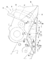
排気装置90は、エンジン12から延びる排気管91とこの排気管91の途中に介在され排気ガスを浄化する触媒室92と、排気管91の後端に接続される消音器93とからなる。消音器93は、右側の同乗者ステップステー49に取付けられる。触媒室92は、金属製の保護部材101で覆われる。また、消音器93の前部は、金属製の化粧カバー102で覆われている。   The exhaust device 90 includes an exhaust pipe 91 extending from the engine 12, a catalyst chamber 92 that is disposed in the middle of the exhaust pipe 91 and purifies exhaust gas, and a silencer 93 connected to the rear end of the exhaust pipe 91. The silencer 93 is attached to the passenger step stay 49 on the right side. The catalyst chamber 92 is covered with a metal protection member 101. The front portion of the silencer 93 is covered with a metallic decorative cover 102.

図2に示すように、エンジン12の下方にて、排気装置90を構成する触媒室92は、保護部材101で覆われている。この保護部材101は、車体カバー40の構成要素としてのミッドカウル42と連続する連続面103を有する。保護部材101は、平板状に形成されると共に、一部に凹部104が形成される。保護部材101とミッドカウル42とが協働して車両の外面を構成するようにした。ミッドカウル42を含む車体カバー40は樹脂により形成され、保護部材101は金属(例えば、薄板鋼板等)で成形される。   As shown in FIG. 2, below the engine 12, the catalyst chamber 92 constituting the exhaust device 90 is covered with a protective member 101. The protective member 101 has a continuous surface 103 that is continuous with a mid cowl 42 as a component of the vehicle body cover 40. The protection member 101 is formed in a flat plate shape, and a recess 104 is formed in part. The protective member 101 and the mid cowl 42 cooperate to form the outer surface of the vehicle. The vehicle body cover 40 including the mid cowl 42 is formed of resin, and the protection member 101 is formed of metal (for example, a thin steel plate).

次に、排気装置の上流側を構成する上流排気管及び触媒室の配置等について説明する。
図3に示すように、シリンダ部の前壁54から2本の排気管(上流排気管95)が延び、2本の上流排気管95は、触媒室92へ連結されている。
Next, the arrangement of the upstream exhaust pipe and the catalyst chamber constituting the upstream side of the exhaust device will be described.
As shown in FIG. 3, two exhaust pipes (upstream exhaust pipes 95) extend from the front wall 54 of the cylinder portion, and the two upstream exhaust pipes 95 are connected to the catalyst chamber 92.

エンジン12のクランク軸を収納するクランクケース51の底部に、オイル溜まりを形成するオイルパン50が配置される。図中、車幅方向中心線Cに対して、オイルパン50は車幅方向左側に配置され、触媒室92は、車幅方向右側に配置される。オイルパン50を車幅方向左側に配置し、触媒室92をクランクケース51の幅W内に収まるように配置し、且つ、触媒室92の下92bをオイルパン50の底面50aに略一致させた。さらに、触媒室92は、オイルパンの外面50b及びクランクケースの底面51aに沿わせるように配置したので、オイルパン50周りをコンパクト化することができる。 An oil pan 50 that forms an oil reservoir is disposed at the bottom of the crankcase 51 that houses the crankshaft of the engine 12. In the figure, the oil pan 50 is disposed on the left side in the vehicle width direction with respect to the center line C in the vehicle width direction, and the catalyst chamber 92 is disposed on the right side in the vehicle width direction. Place the oil pan 50 in the vehicle width direction left, arranged to fit the catalyst chamber 92 within the width W of the crankcase 51, and the lower portion 92b of the catalyst chamber 92 is substantially equal to the bottom surface 50a of the oil pan 50 It was. Furthermore, since the catalyst chamber 92 is disposed along the outer surface 50b of the oil pan and the bottom surface 51a of the crankcase, the periphery of the oil pan 50 can be made compact.

図4に示すように、排気装置90は、エンジン(図3、符号12)から略下方に延び触媒室92の上流端に接続される上流排気管95、95と、これらの上流排気管95、95の後端に接続され排気ガスを浄化する触媒ユニット(図5、符号97)を内蔵するケース状の触媒室92と、この触媒室92の後端から車両後方へ延びている下流排気管96とでその前半部を構成する。排気装置90の触媒室92に、前述した保護部材101が取付けられている。   As shown in FIG. 4, the exhaust device 90 includes upstream exhaust pipes 95, 95 extending substantially downward from the engine (FIG. 3, reference numeral 12) and connected to the upstream end of the catalyst chamber 92, and these upstream exhaust pipes 95, 95, a case-like catalyst chamber 92 that contains a catalyst unit (reference numeral 97 in FIG. 5) that purifies exhaust gas, and a downstream exhaust pipe 96 that extends from the rear end of the catalyst chamber 92 to the rear of the vehicle. And the first half is composed. The protective member 101 described above is attached to the catalyst chamber 92 of the exhaust device 90.

図5に示すように、排気装置90の触媒室92は、触媒室92の上端部から上方に突設した取付ステー106で車体フレーム側の部材119へ取付けられる。次に、保護部材101は、触媒室92の前部に接合した第1支持ステー111と、触媒室92の後部に接合した第2支持ステー112と、下流排気管96に接合した第3支持ステー113とに取付けられている。   As shown in FIG. 5, the catalyst chamber 92 of the exhaust device 90 is attached to the member 119 on the vehicle body frame side by an attachment stay 106 protruding upward from the upper end portion of the catalyst chamber 92. Next, the protection member 101 includes a first support stay 111 joined to the front portion of the catalyst chamber 92, a second support stay 112 joined to the rear portion of the catalyst chamber 92, and a third support stay joined to the downstream exhaust pipe 96. 113.

触媒室92の上部には、センサ部品115が取付けられる。保護部材101は、センサ部品115を触媒室92と共に覆うように形成されている。すなわち、保護部材101で触媒室92とセンサ部品115とを覆うようにした。別個にセンサ部品115を覆う専用部品は不要になるため、部品点数の増加を抑制することができる。   A sensor component 115 is attached to the upper part of the catalyst chamber 92. The protection member 101 is formed so as to cover the sensor component 115 together with the catalyst chamber 92. That is, the protection chamber 101 covers the catalyst chamber 92 and the sensor component 115. Since a dedicated component that separately covers the sensor component 115 is not required, an increase in the number of components can be suppressed.

次に、保護部材の裏面に貼り付けた箔状部材について説明する。
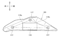
図6に示すように、保護部材101をその裏側の車幅方向内方から見たとき、保護部材101に矩形状を呈する金属製の箔状部材116が貼り付けられている。この箔状部材116は、その左右の角部116s、116sが、各々、締結用の第1ねじ(図7、符号121)と第2ねじ(図7、符号122)が締結される孔部117、117の中心を結ぶ線L1上及び第2ねじ122と第3ねじ(図7、符号123)が締結される孔部117、117の中心を結ぶ線L2上に位置するように、保護部材101に貼り付けられている。保護部材101に金属製の箔状部材116を貼り付けたので、保護部材101の面剛性を向上させることができ、保護部材101の振動を低減することが可能になる。
Next, the foil member attached to the back surface of the protective member will be described.
As shown in FIG. 6, when the protection member 101 is viewed from the inner side in the vehicle width direction on the back side, a metal foil member 116 having a rectangular shape is attached to the protection member 101. In this foil-like member 116, the left and right corners 116s, 116s are respectively hole portions 117 in which the first screw (FIG. 7, reference numeral 121) and the second screw (FIG. 7, reference numeral 122) for fastening are fastened. The protective member 101 is positioned on the line L1 connecting the centers of 117 and on the line L2 connecting the centers of the holes 117 and 117 where the second screw 122 and the third screw (reference numeral 123) are fastened. Is pasted. Since the metal foil-like member 116 is attached to the protective member 101, the surface rigidity of the protective member 101 can be improved, and the vibration of the protective member 101 can be reduced.

次の図7〜11では、触媒室及び保護部材の支持構造等について説明する。
図7に示すように、触媒室92に上方へ取付ステー106が突設され、この取付ステー106は、触媒固定ボルト118によって車体フレーム側の部材(図5、符号119)へ取付けられる。次に、保護部材101は、第1ねじ121で第1支持ステー111に取付けられ、第2ねじ122で第2支持ステー112に取付けられ、第3ねじ123で第3支持ステー113に取付けられる。保護部材101と第1〜第3支持ステー111、112、113の間に、各々、弾性部材129が介在されており、保護部材101はラバーマウントされている。
Next, FIGS. 7 to 11 will explain the support structure of the catalyst chamber and the protective member.
As shown in FIG. 7, a mounting stay 106 protrudes upward from the catalyst chamber 92, and this mounting stay 106 is attached to a member (FIG. 5, reference numeral 119) on the vehicle body frame by a catalyst fixing bolt 118. Next, the protection member 101 is attached to the first support stay 111 with the first screw 121, attached to the second support stay 112 with the second screw 122, and attached to the third support stay 113 with the third screw 123. Between the protective member 101 of the first to third support stay 111,11 2,1 13, respectively, the elastic member 129 is interposed, the protective member 101 is rubber mounts.

消音器93に、化粧カバー102が取付けられる締結部125が設けられ、この締結部125に第4ねじ124で化粧カバー102が締結される。締結部125の後方にて消音器93に、化粧カバー係止部126が接合され、この化粧カバー係止部126に化粧カバーの係合部217が係合可能に設けられている。   The silencer 93 is provided with a fastening portion 125 to which the decorative cover 102 is attached, and the decorative cover 102 is fastened to the fastening portion 125 with a fourth screw 124. A decorative cover engaging portion 126 is joined to the silencer 93 behind the fastening portion 125, and an engaging portion 217 of the decorative cover is provided on the decorative cover engaging portion 126 so as to be engageable therewith.

次に、排気装置を構成する触媒室の支持構造について説明する。
図8に示すように、触媒室92に接合される取付ステー106は、車両後方から見て略L字状を呈する内部材107と外部材108とを互いの背面を突き合わせてなる。内部材107は、脚部107aと、この脚部107aから上に延びている縦部107bとからなる。同様に、外部材108は、脚部108aと縦部108bとからなる。脚部107a、108aと縦部107b、108bの間は、各々、半径RのR部109、109で滑らかに渡されているので、R部109、109への応力集中が回避される。
Next, the support structure of the catalyst chamber constituting the exhaust device will be described.
As shown in FIG. 8, the mounting stay 106 joined to the catalyst chamber 92 is formed by abutting the back surfaces of an inner member 107 and an outer member 108 that are substantially L-shaped when viewed from the rear of the vehicle. The inner member 107 includes a leg portion 107a and a vertical portion 107b extending upward from the leg portion 107a. Similarly, the outer member 108 includes a leg portion 108a and a vertical portion 108b. Since the leg portions 107a and 108a and the vertical portions 107b and 108b are smoothly passed by the R portions 109 and 109 having the radius R, stress concentration on the R portions 109 and 109 is avoided.

取付ステー106の内面106bにウエルドナット110aが接合され、ウエルドナット110に対応した位置にて取付ステー106の外面106aに、車体フレーム側の部材119の孔部117を合わせ、触媒固定ボルト118で車体フレーム側の部材119へ排気装置90の触媒室92が取付けられる。   A weld nut 110 a is joined to the inner surface 106 b of the mounting stay 106, the hole 117 of the member 119 on the vehicle body frame side is aligned with the outer surface 106 a of the mounting stay 106 at a position corresponding to the weld nut 110, and the vehicle body is secured by the catalyst fixing bolt 118. The catalyst chamber 92 of the exhaust device 90 is attached to the frame-side member 119.

次に、触媒室92のラバーマウント支持構造について説明する。触媒固定ボルトの軸部118Jの周囲にカラー128が挿入され、予め、車体フレーム側の部材119の孔部117に嵌入した弾性部材127、127へ、カラー128と一体にした触媒固定ボルト118を挿入し、取付ステー106側に固着されるウエルドナット110aへ触媒固定ボルト118を締結する。すなわち、触媒室92はラバーマウントされているので、触媒室92の振動が車体フレーム側の部材119に伝わり難くなり、併せて、車体フレーム側の部材119の振動が触媒室92に伝わり難くなる。   Next, the rubber mount support structure of the catalyst chamber 92 will be described. The collar 128 is inserted around the shaft portion 118J of the catalyst fixing bolt, and the catalyst fixing bolt 118 integrated with the collar 128 is inserted into the elastic members 127 and 127 fitted in the holes 117 of the member 119 on the vehicle body frame side in advance. Then, the catalyst fixing bolt 118 is fastened to the weld nut 110a fixed to the mounting stay 106 side. That is, since the catalyst chamber 92 is rubber-mounted, the vibration of the catalyst chamber 92 is hardly transmitted to the member 119 on the vehicle body frame side, and at the same time, the vibration of the member 119 on the vehicle body frame side is difficult to be transmitted to the catalyst chamber 92.

次の図9〜13では、保護部材の支持構造等について詳しく説明する。
図9に示すように、触媒室92の底面131と外側面132とに、第1支持ステー111が当接されると共に接合される。そして、第1支持ステー111の座面133に、保護部材101が当接され、第1ねじ121及びウエルドナット110bを介して第1支持ステー111に保護部材101が取付けられる。
Next, in FIGS. 9 to 13, a support member supporting structure and the like will be described in detail.
As shown in FIG. 9, the first support stay 111 is brought into contact with and joined to the bottom surface 131 and the outer surface 132 of the catalyst chamber 92. The protection member 101 is brought into contact with the seat surface 133 of the first support stay 111, and the protection member 101 is attached to the first support stay 111 via the first screw 121 and the weld nut 110b.

触媒室92は、長円状断面を有する長円部134の中心134Jを基準に、車両後面視で、水平面に対して長円部134の外側が角度θだけ上方に傾斜するように配置したので、車両のバンク角をかせぎ易い。次図にて、触媒室92のラバーマウント構造について説明する。   The catalyst chamber 92 is arranged so that the outer side of the oval part 134 is inclined upward by an angle θ with respect to the horizontal plane in the rear view of the vehicle with reference to the center 134J of the oval part 134 having an oval cross section. The bank angle of the vehicle is easy to earn. The rubber mount structure of the catalyst chamber 92 will be described with reference to the next figure.

図10に示すように、保護部材101に断面皿状を呈し第1ねじ121が締結される孔117を有する孔付き凹部104を形成し、この孔付き凹部104に弾性部材129及びカラー128を嵌め、第1ねじ121及びウエルドナット110bで保護部材101を第1支持ステー111に取付ける。なお、後述する第2支持ステー及び第3支持ステーへの取付構造についても上記と同様な構造のラバーマウント支持であり、説明を省略する。 As shown in FIG. 10, the first screw 121 presents a cross-section dish-shaped protective member 101 forms a perforated recess 104 having a hole 117 to be fastened, the elastic member 129 and the collar 128 to the perforated recess 104 The protective member 101 is attached to the first support stay 111 with the first screw 121 and the weld nut 110b. Note that the mounting structure to the second support stay and the third support stay, which will be described later, is a rubber mount support having the same structure as described above, and a description thereof will be omitted.

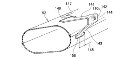
図11に示すように、触媒室92の天井面130と外側面132とに、第2支持ステー112が当接されると共に接合される。第2支持ステー112は、触媒室92の天井面130から車両外方へ延びる第1延設部141と、この第1延設部141の外端から下方へ延び保護部材101が取付けられる縦部142と、この縦部142の下端から触媒室92の外側面132へ延びる第2延設部143とからなる。そして、第2支持ステー112の縦部142の一部を構成する座面144に、保護部材101が当接され、第2ねじ122及びウエルドナット110cを介して第2支持ステー112に保護部材101が取付けられる。   As shown in FIG. 11, the second support stay 112 is brought into contact with and joined to the ceiling surface 130 and the outer surface 132 of the catalyst chamber 92. The second support stay 112 includes a first extending portion 141 that extends from the ceiling surface 130 of the catalyst chamber 92 to the outside of the vehicle, and a vertical portion that extends downward from the outer end of the first extending portion 141 and to which the protection member 101 is attached. 142 and a second extending portion 143 extending from the lower end of the vertical portion 142 to the outer side surface 132 of the catalyst chamber 92. Then, the protection member 101 is brought into contact with a seating surface 144 constituting a part of the vertical portion 142 of the second support stay 112, and the protection member 101 is brought into contact with the second support stay 112 via the second screw 122 and the weld nut 110c. Is installed.

図12に示すように、触媒室92に接合される第1延設部141と第2延設部143の端部は、各々、触媒室92の長手軸方向に延びる第1せり出し部147及び第2せり出し部148を有し、これらの第1せり出し部147及び第2せり出し部148が、接合部149、150の一部となる。これらの第1せり出し部147及び第2せり出し部148により、接合部149、150が長くなり、接合部149、150での応力集中が回避される。   As shown in FIG. 12, the end portions of the first extending portion 141 and the second extending portion 143 joined to the catalyst chamber 92 are respectively a first protruding portion 147 and a first protruding portion 147 extending in the longitudinal axis direction of the catalyst chamber 92. There are two protruding portions 148, and the first protruding portion 147 and the second protruding portion 148 become a part of the joint portions 149 and 150. The first projecting portion 147 and the second projecting portion 148 make the joint portions 149 and 150 longer, and stress concentration at the joint portions 149 and 150 is avoided.

図13に示すように、下流排気管96の上面151と下側面152とに、第3支持ステー113が当接されると共に接合される。第3支持ステー113は、下流排気管の上面151から車両外方へ延びる延設上部153と、この延設上部153の外端から下方へ延び保護部材101が取付けられる座部154と、この座部154の下端から下流排気管96の下側面152に延びる延設下部155とからなる。そして、第3支持ステー113の座部154に、保護部材101が当接され、第3ねじ123及びウエルドナット110dを介して第3支持ステー113に保護部材101が取付けられる。   As shown in FIG. 13, the third support stay 113 is brought into contact with and joined to the upper surface 151 and the lower side surface 152 of the downstream exhaust pipe 96. The third support stay 113 includes an extended upper part 153 that extends outward from the upper surface 151 of the downstream exhaust pipe, a seat part 154 that extends downward from the outer end of the extended upper part 153 and to which the protection member 101 is attached. The lower portion 155 extends from the lower end of the portion 154 to the lower surface 152 of the downstream exhaust pipe 96. The protective member 101 is brought into contact with the seat 154 of the third support stay 113, and the protective member 101 is attached to the third support stay 113 via the third screw 123 and the weld nut 110d.

ここで、座部154と延設下部155との間は、従来の半径Rbに較べて大きな半径R2(Rb<R2)とし、座部154と延設下部155との間を、半径R2のR2部156で滑らかに渡すことで、下流排気管96の下側面152に延びる延設下部155の長さを長くした。このように、延設下部155を長くして延設上部153との長さを略同一に揃えることで、従来の第3支持ステー(図想像線で示す。)に較べて、第3支持ステー113にかかる荷重に偏りを生じ難くできる。   Here, the radius R2 (Rb <R2) larger than the conventional radius Rb is set between the seat portion 154 and the extended lower portion 155, and the radius R2 between the seat portion 154 and the extended lower portion 155 is R2. The length of the extended lower portion 155 extending to the lower surface 152 of the downstream exhaust pipe 96 is increased by passing the portion smoothly at the portion 156. In this way, by extending the extended lower portion 155 and making the length of the extended upper portion 153 substantially the same, the third support stay is compared with the conventional third support stay (shown by the imaginary line in the figure). It is possible to make it difficult for the load applied to 113 to be uneven.

次に、上記をまとめて説明する。図5、図7にて、排気装置90は、内部に触媒ユニット97を包含した触媒室92を有し、この触媒室92の上部92a及び下部92bで保護部材101が保持される。さらに、排気装置90は、触媒室92の前端部92cに接続される上流排気管95、95と、触媒室92の後端部92dに接続される下流排気管96とを有し、さらに、保護部材101は、下流排気管96の第3支持ステー113にも保持される。   Next, the above will be described together. 5 and 7, the exhaust device 90 has a catalyst chamber 92 including a catalyst unit 97 inside, and the protection member 101 is held by the upper portion 92 a and the lower portion 92 b of the catalyst chamber 92. Further, the exhaust device 90 includes upstream exhaust pipes 95 and 95 connected to the front end portion 92c of the catalyst chamber 92, and a downstream exhaust pipe 96 connected to the rear end portion 92d of the catalyst chamber 92, and further includes protection. The member 101 is also held by the third support stay 113 of the downstream exhaust pipe 96.

触媒室92の上下2カ所で保護部材101が保持されるので、特に、上下振動に対する保護部材101の取付剛性を高めることができる。さらに、保護部材101は、触媒室の上部92a及び下部92bで保持される上に、保護部材101の後部が下流排気管96に保持される。排気装置90にかかる上下方向の振動に加え、保護部材101の前部又は後部が保持されるので、旋回時の車幅方向振動(振れ)に対しても排気装置90の取付剛性を高めることができる。
なお、保護部材は、下流排気管に支持されているが、上流排気管に支持されるようにする、あるいは、上流排気管と下流排気管の双方に支持されるようにしても良い。
Since the protective member 101 is held at the upper and lower portions of the catalyst chamber 92, the mounting rigidity of the protective member 101 against vertical vibration can be particularly improved. Further, the protection member 101 is held by the upper part 92a and the lower part 92b of the catalyst chamber, and the rear part of the protection member 101 is held by the downstream exhaust pipe 96. Since the front part or the rear part of the protection member 101 is held in addition to the vertical vibration applied to the exhaust device 90, the mounting rigidity of the exhaust device 90 can be increased even with respect to vibration in the vehicle width direction (vibration) during turning. it can.
The protective member is supported by the downstream exhaust pipe, but may be supported by the upstream exhaust pipe, or may be supported by both the upstream exhaust pipe and the downstream exhaust pipe.

保護部材101は、触媒室92の全体を覆うように略三角形状に形成される。略三角形状の保護部材101の中央部に触媒室92を配置し、略三角形状の保護部材101の頂点に近い位置にて触媒室92を保持させるようにした。略三角形状の保護部材101によって、触媒室92全体が覆われると共に、保護部材101を触媒室92に確実に支持させることができる。   The protection member 101 is formed in a substantially triangular shape so as to cover the entire catalyst chamber 92. The catalyst chamber 92 is disposed in the center of the substantially triangular protective member 101 so that the catalyst chamber 92 is held at a position close to the apex of the substantially triangular protective member 101. The entire catalyst chamber 92 is covered by the substantially triangular protection member 101, and the protection member 101 can be reliably supported by the catalyst chamber 92.

次の図14〜15では、上流排気管の下流端について説明する。
図14に示すように、平面視で、上流排気管95、95の下流端105、105における軸線98、98は、触媒室92の長手軸94方向に対し角度αだけ傾斜している。すなわち、上流排気管95の下流端105の向きを触媒室92の長手軸94に対して角度αだけ傾斜させたので、触媒ユニット97へ排気ガスが接触する面積が増え排気ガスの接触量が増える。
Next, in FIGS. 14 to 15, the downstream end of the upstream exhaust pipe will be described.
As shown in FIG. 14, the axial lines 98, 98 at the downstream ends 105, 105 of the upstream exhaust pipes 95, 95 are inclined by an angle α with respect to the longitudinal axis 94 direction of the catalyst chamber 92 in plan view. That is, since the direction of the downstream end 105 of the upstream exhaust pipe 95 is inclined by the angle α with respect to the longitudinal axis 94 of the catalyst chamber 92, the area where the exhaust gas contacts the catalyst unit 97 increases and the contact amount of the exhaust gas increases. .

図15に示すように、図14の実施例に対して異なる点は、上流排気管の下流端105、105に触媒ユニット97側へ筒状のカラー部材99、99が延びている点にあり、その他の構成は同一である。触媒室の入力側端部からカラー部材99、99を突出させた。   As shown in FIG. 15, the difference from the embodiment of FIG. 14 is that cylindrical collar members 99, 99 extend toward the catalyst unit 97 at the downstream ends 105, 105 of the upstream exhaust pipe. Other configurations are the same. The collar members 99 and 99 are protruded from the input side end of the catalyst chamber.

図15では、触媒室92内にカラー部材99、99を突出させた。
図14では、触媒室92内に上流排気管の下流端105、105が突出していないため、各気筒間で排気タイミングの差異によって、これらの排気管95、95内を流れる排気ガス同士が影響し合う現象(排気干渉)が起き易い。
この点、図15では、上流排気管の下流端105、105に触媒ユニット97側へ突出するカラー部材99、99を突出させたので、排気干渉を抑えることができる。
In FIG. 15, the collar members 99 and 99 are protruded into the catalyst chamber 92.
In FIG. 14, since the downstream ends 105, 105 of the upstream exhaust pipe do not protrude into the catalyst chamber 92, the exhaust gas flowing through these exhaust pipes 95, 95 is influenced by the difference in exhaust timing between the cylinders. The matching phenomenon (exhaust interference) is likely to occur.
In this regard, in FIG. 15, since the collar members 99 and 99 projecting toward the catalyst unit 97 are projected at the downstream ends 105 and 105 of the upstream exhaust pipe, exhaust interference can be suppressed.

次に、排気装置の下流側を構成する消音器について説明する。
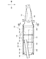
図16に示すように、消音器93は、上流端に設けられる円錐状の円錐外筒161と、この円錐外筒161の後端に接続される外筒162と、この外筒162の内側に支持される内筒163と、この内筒163の長手軸直角方向に延びて内筒163を仕切る第1セパレータ164及び第2セパレータ165と、内筒163の後端部を塞ぐリヤキャップ166とを有する。
Next, the silencer that configures the downstream side of the exhaust device will be described.
As shown in FIG. 16, the silencer 93 includes a conical outer cylinder 161 provided at the upstream end, an outer cylinder 162 connected to the rear end of the conical outer cylinder 161, and an inner side of the outer cylinder 162. An inner cylinder 163 that is supported, a first separator 164 and a second separator 165 that extend in a direction perpendicular to the longitudinal axis of the inner cylinder 163 to partition the inner cylinder 163, and a rear cap 166 that closes the rear end portion of the inner cylinder 163. Have.

消音器93は、第1セパレータ164の車両前方にて第1セパレータ164と円錐外筒161とで形成される空間を第1室167とし、第1セパレータ164と第2セパレータ165で仕切られた空間を第2室168とし、第2セパレータ165とリヤキャップ166とで仕切られた空間を第3室169とするとき、円錐外筒161に、円錐外筒161の内側後方へ第1室167に突出される前パイプ190と、第1セパレータ164及び第2セパレータ165に支持され第1室167から第3室169へ排気ガスを流す第1パイプ191と、第2セパレータ165に支持され第3室169から第2室168へ排出ガスを流す第2パイプ192と、第2セパレータ165とリヤキャップ166に支持され第2室168から外方へ排気ガスを流すテールパイプ193とを有する。テールパイプ193の長手方向略中央部に、バイパス用のバイパス孔194を開けた。   The silencer 93 has a space formed by the first separator 164 and the conical outer cylinder 161 in front of the first separator 164 in the vehicle as a first chamber 167, and is a space partitioned by the first separator 164 and the second separator 165. Is the second chamber 168, and the space partitioned by the second separator 165 and the rear cap 166 is the third chamber 169, the conical outer cylinder 161 protrudes into the first chamber 167 inward and rearward of the conical outer cylinder 161. The first pipe 191 that is supported by the first separator 164 and the second separator 165 and flows the exhaust gas from the first chamber 167 to the third chamber 169, and the third chamber 169 that is supported by the second separator 165. From the second chamber 168 supported by the second pipe 192, the second separator 165, and the rear cap 166 for flowing the exhaust gas from the second chamber 168 to the second chamber 168. And a tail pipe 193. A bypass hole 194 for bypassing was formed in a substantially central portion in the longitudinal direction of the tail pipe 193.

下流排気管96から消音器93に入った排気ガスは、前パイプ190を通って第1室167に達し、第1室167の排気ガスは、第1パイプ191を通って第3室169に達し、第3室169から第2パイプを通って第2室168に達し、第2室168からテールパイプ193を通って外方へ排出される。   The exhaust gas that has entered the silencer 93 from the downstream exhaust pipe 96 reaches the first chamber 167 through the front pipe 190, and the exhaust gas in the first chamber 167 reaches the third chamber 169 through the first pipe 191. The third chamber 169 passes through the second pipe to reach the second chamber 168, and is discharged from the second chamber 168 through the tail pipe 193 to the outside.

図17に示すように、前パイプの後端部200は、内方に凹ませ略三日月状を呈する凹み部201が形成されている。この凹み部201により、排気ガスの流れる向きが所定方向にガイドされる。   As shown in FIG. 17, the rear end portion 200 of the front pipe is formed with a recessed portion 201 that is recessed inward and has a substantially crescent shape. The direction in which the exhaust gas flows is guided in a predetermined direction by the recess 201.

図18に示すように、円錐外筒161に断面円弧形状の遮熱板202が接合される。この遮熱板202は、消音内に流入してくる排気ガスが円錐外筒161の内壁160に直接当たらないようにガードするものである。遮熱板202の表面形状には、様々な形態が適用可能である。その詳細については後述する。 As shown in FIG. 18, a heat shield plate 202 having a circular arc cross section is joined to the conical outer cylinder 161. The heat shield plate 202, the exhaust gases come to flow into the silencer is to guard so as not directly hit the inner wall 160 of the conical outer cylinder 161. Various forms can be applied to the surface shape of the heat shield plate 202. Details thereof will be described later.

図19に示すように、遮熱板202は、円錐外筒161の側面203から下面204にかけて、円錐外筒の内面(又は内壁200)に貼り付けられている。排気ガスは内壁200に貼り付けられた遮熱板202でガードされるので、排気ガスが直接円錐外筒161に当たらなくすることができる。   As shown in FIG. 19, the heat shield plate 202 is attached to the inner surface (or inner wall 200) of the conical outer cylinder from the side surface 203 to the lower surface 204 of the conical outer cylinder 161. Since the exhaust gas is guarded by the heat shield plate 202 attached to the inner wall 200, the exhaust gas can be prevented from directly hitting the conical outer cylinder 161.

次に、遮熱板202の表面形状について説明する。
図20(a)に示すように、遮熱板202は、表面に多数の孔196を有する多孔板206である。このような多孔板206とすることで、多孔板206に当たった排気ガスは第1室(図16、符号167)で拡散され易くなる。
Next, the surface shape of the heat shield plate 202 will be described.
As shown in FIG. 20A, the heat shield plate 202 is a porous plate 206 having a large number of holes 196 on the surface. By using such a porous plate 206, the exhaust gas hitting the porous plate 206 is easily diffused in the first chamber (FIG. 16, reference numeral 167).

図20(b)は、図20(a)の別実施例であり、図20(c)は図20(a)の更なる別実施例である。
図20(b)に示すように、遮熱板202の表面に、略半球状の多数の凸部207が形成されている。
FIG. 20 (b) is another embodiment of FIG. 20 (a), and FIG. 20 (c) is a further embodiment of FIG. 20 (a).
As shown in FIG. 20B, a large number of substantially hemispherical convex portions 207 are formed on the surface of the heat shield plate 202.

図20(c)に示すように、遮熱板の表面に、断面円弧帯状で凸状の多数の帯部208を形成しても良い。このように、遮熱板202の表面形状を凹凸にすることで、遮熱板202に当たった排気ガスは拡散され易くなる。   As shown in FIG. 20C, a large number of belt portions 208 having a circular arc cross section and a convex shape may be formed on the surface of the heat shield plate. Thus, by making the surface shape of the heat shield plate 202 uneven, the exhaust gas hitting the heat shield plate 202 is easily diffused.

次に、前パイプの凹み部と遮熱板とを組み合わせた作用について説明する。
図21(b)の比較例に示すように、前パイプ190を出た排気ガスの一部は、第1室の円錐外筒161の内壁160に直接当たる。このため、高温の排気ガスが当たった円錐外筒161の温度が局部的に上昇し、外壁の一部が変色することがあり、外観上改良の余地があった。
Next, the effect | action which combined the recessed part and heat shield board of the front pipe is demonstrated.
As shown in the comparative example of FIG. 21B, a part of the exhaust gas that exits the front pipe 190 directly hits the inner wall 160 of the conical outer cylinder 161 in the first chamber. For this reason, the temperature of the conical outer cylinder 161 hit with the high-temperature exhaust gas locally rises, and part of the outer wall may be discolored, so there is room for improvement in appearance.

この点、本発明では、図21(a)の実施例に示すように、排気ガスは、前パイプ190の凹み部201によって、排気ガスの向きが変わり、直接第1室の円錐外筒161の内壁に直接当たり難くなる。加えて、表面に多数の孔(図20、符号196)を有する遮熱板202を前パイプ190の口から出た排気ガスが当たる部位にて、円錐外筒161の内壁160に貼り付けたので、排気ガスは円錐外筒161の内壁160に直接当たり難くなると共に、円錐外筒161に当たった排気ガスは、多孔板状の遮熱板202によって、撹拌される。従って、円錐外筒161の温度上昇が抑えられ、外壁の一部が変色すると言う問題を解消できる。   In this regard, in the present invention, as shown in the embodiment of FIG. 21A, the direction of the exhaust gas is changed by the recess 201 of the front pipe 190, and the conical outer cylinder 161 of the first chamber directly changes. It becomes difficult to hit the inner wall directly. In addition, because the heat shield plate 202 having a large number of holes (FIG. 20, reference numeral 196) on the surface is attached to the inner wall 160 of the conical outer cylinder 161 at the portion where the exhaust gas coming out from the mouth of the front pipe 190 hits. The exhaust gas is less likely to directly hit the inner wall 160 of the conical outer cylinder 161, and the exhaust gas striking the conical outer cylinder 161 is agitated by the perforated heat shield plate 202. Therefore, the temperature rise of the conical outer cylinder 161 is suppressed, and the problem that a part of the outer wall is discolored can be solved.

次に、消音器の円錐外筒に取付けられる化粧カバーの支持構造について説明する。
図22(a)は、円錐外筒に取付けられる化粧カバーフックの斜視図、図22(b)は図22(b)−(b)断面図であり、図22(c)は化粧カバーフックの平面図である。
Next, the support structure of the decorative cover attached to the conical outer cylinder of the silencer will be described.
22 (a) is a perspective view of a decorative cover hook attached to a conical outer cylinder, FIG. 22 (b) is a sectional view of FIGS. 22 (b)-(b), and FIG. 22 (c) is a diagram of the decorative cover hook. It is a top view.

図22(a)に示すように、化粧カバーフック211、211は、各々、円錐外筒161に接合される座部214、214と、座部214、214の端部から立ち上げた縦部215、215と、縦部215、215の上端から座部214、214の側に各々折り曲げられ化粧カバーの係合部(図7、符号217、217)が係止される係止爪216、216とからなる。   As shown in FIG. 22 (a), the decorative cover hooks 211 and 211 are seat portions 214 and 214 joined to the conical outer cylinder 161, and vertical portions 215 raised from the end portions of the seat portions 214 and 214, respectively. 215, and locking claws 216, 216 that are bent from the upper ends of the vertical portions 215, 215 toward the seats 214, 214, respectively, and the engaging portions (FIG. 7, reference numerals 217, 217) of the decorative cover are locked. Consists of.

2つの化粧カバーフック211、211の形状は同一の形状のため、以下説明では、代表して1つの化粧カバーフック211の構造のみを説明する。
図22(c)において、係止爪216の幅W1は、縦部215の幅W2よりも狭くした(W1<W2)。図22(a)において、座部214の左右辺214L、214Rに、内側へU字状に切り欠いたU字切欠部218、218を形成し、座部214の幅を一部狭めるようにしたことで、溶接部近傍での応力集中を回避させることができる。
Since the two decorative cover hooks 211 and 211 have the same shape, in the following description, only the structure of the single decorative cover hook 211 will be described as a representative.
In FIG. 22C, the width W1 of the locking claw 216 is narrower than the width W2 of the vertical portion 215 (W1 <W2). In FIG. 22 (a), U-shaped notches 218 and 218 that are notched inwardly in a U-shape are formed on the left and right sides 214L and 214R of the seat 214, so that the width of the seat 214 is partially reduced. Thus, stress concentration in the vicinity of the weld can be avoided.

図22(b)に示すように、座部214と縦部215の間は、半径R3のR3部219で渡される。また、縦部215と係止爪216との間は、半径R4のR4部221で渡される。ここで、幅の広い座部214及び縦部215に渡されるR3部219の半径R3と、幅の狭い係止爪216と縦部215に渡されるR4部221の半径R4の関係を、R3<R4とすることで、強度バランスの良い形状とした。さらに、座部214と係止爪216の向き同方向に延ばし化粧カバーフック211の形状をコ字状とし同じ向きに曲げることで、形状変更の自由度を高めるようにした。   As shown in FIG. 22B, the space between the seat portion 214 and the vertical portion 215 is passed by an R3 portion 219 having a radius R3. Further, the R4 portion 221 having a radius R4 is passed between the vertical portion 215 and the locking claw 216. Here, the relationship between the radius R3 of the R3 portion 219 passed to the wide seat portion 214 and the vertical portion 215, and the radius R4 of the R4 portion 221 passed to the narrow locking claw 216 and the vertical portion 215 is expressed as R3 < By setting it to R4, it was set as the shape with a sufficient strength balance. Furthermore, the direction of the seat portion 214 and the locking claw 216 is extended in the same direction, and the shape of the decorative cover hook 211 is made U-shaped and bent in the same direction, thereby increasing the degree of freedom of shape change.

以上に述べた小型車両の作用を次に述べる。
図23(a)の実施例に示すように、排気装置90の側方を覆う保護部材101は、車体カバー40と連続する連続面103を有し、この保護部材101と車体カバー40とが協働して車両の外面を構成するようにした。
The operation of the small vehicle described above will be described next.
As shown in the embodiment of FIG. 23A, the protective member 101 that covers the side of the exhaust device 90 has a continuous surface 103 that is continuous with the vehicle body cover 40, and the protective member 101 and the vehicle body cover 40 cooperate with each other. Worked to configure the outer surface of the vehicle.

一方、図23(b)の比較例に示すように、排気装置の側方を覆う保護部材101Bは、車体カバー40Bの構成要素であるミッドカウル42Bと連続する連続面を有していない。保護部材101Bとの境界部にてミッドカウル42Bは、外気を取り入れる前面開口231Bと、車体フレームへ延ばされ第1ねじ121Bが締結される取付部232Bとを有しており、ミッドカウル42Bと保護部材101Bとの意匠面での連係に改良の余地があった。   On the other hand, as shown in the comparative example of FIG. 23 (b), the protective member 101B that covers the side of the exhaust device does not have a continuous surface that is continuous with the mid cowl 42B that is a component of the vehicle body cover 40B. The mid cowl 42B has a front opening 231B that takes in outside air and a mounting portion 232B that extends to the vehicle body frame and is fastened with the first screw 121B at the boundary with the protective member 101B. There was room for improvement in the design of the protection member 101B in terms of design.

本発明では、図23(a)の実施例のように、保護部材101に車体カバー40と連続する連続面103をもたせたので、車体カバー40に、排気装置の側方を覆い隠す形状をもたせる必要はない。結果、車体カバー形状の自由度を高めながら排気装置90を保護部材101で覆うことができる。車体カバー形状の自由度が高まるため、車両の外観性を高めることができる。   In the present invention, since the protective member 101 has the continuous surface 103 continuous with the vehicle body cover 40 as in the embodiment of FIG. 23A, the vehicle body cover 40 has a shape that covers the side of the exhaust device. There is no need. As a result, the exhaust device 90 can be covered with the protective member 101 while increasing the degree of freedom of the body cover shape. Since the freedom degree of a vehicle body cover shape increases, the external appearance property of a vehicle can be improved.

この他、図23(b)の比較例にて、排気装置90を覆う保護部材は、排気装置90よりも車幅方向内方に配置される車体フレームに取付けられている。車体フレームに取付けられる保護部材の一部が車幅方向内方へ延ばされるため、保護部材の形状自由度が制約される場合があった。   In addition, in the comparative example of FIG. 23B, the protective member that covers the exhaust device 90 is attached to a vehicle body frame that is disposed inward in the vehicle width direction relative to the exhaust device 90. Since a part of the protective member attached to the vehicle body frame is extended inward in the vehicle width direction, the shape freedom of the protective member may be restricted.

この点、本発明では、図23(a)の実施例のように、保護部材101は、車体フレーム11に較べて近い側に位置する排気装置90に取付けられている。車体フレーム11に較べ、保護部材101の近傍に配置される排気装置90に、保護部材101を取付けたので、保護部材101の一部を延ばす等の手段は不要になる。結果、保護部材101の形状自由度を高めることができる。   In this regard, in the present invention, as in the embodiment of FIG. 23A, the protection member 101 is attached to the exhaust device 90 positioned closer to the vehicle body frame 11. Compared to the vehicle body frame 11, the protection member 101 is attached to the exhaust device 90 disposed in the vicinity of the protection member 101, so that means such as extending a part of the protection member 101 are not necessary. As a result, the degree of freedom of shape of the protection member 101 can be increased.

また、保護部材101は金属で成形され、図7に示すように、弾性部材129を介して排気装置90に取付けられる。保護部材101と排気装置90との間に介在された弾性部材129によって、排気装置90から弾性部材129に振動が伝わり難くなり、保護部材101に排気装置90に対する共振現象が起こり難くなる。保護部材101には、凹部104(凹部104a、104b)が形成されている。これらの凹部104a、104bにより保護部材101の剛性が高められる。保護部材101の剛性向上によって、触媒室92との共振現象を一層抑制することができる。   The protective member 101 is formed of metal and is attached to the exhaust device 90 via an elastic member 129 as shown in FIG. The elastic member 129 interposed between the protection member 101 and the exhaust device 90 makes it difficult for vibration to be transmitted from the exhaust device 90 to the elastic member 129, so that the resonance phenomenon with respect to the exhaust device 90 does not easily occur in the protection member 101. The protection member 101 has a recess 104 (recesses 104a and 104b). The rigidity of the protective member 101 is increased by the recesses 104a and 104b. By improving the rigidity of the protection member 101, the resonance phenomenon with the catalyst chamber 92 can be further suppressed.

図1、図5及び図7にて、車体フレーム11に車体カバー40が取付けられ、排気装置90に保護部材101が弾性部材129を介して取付けられている。車体カバー40と保護部材101とで支持部材が異なると、車両に生ずる振動等により、車体カバー40と保護部材101の間の合わせ部(図9、符号222)に隙間等が生ずる可能性がある。   1, 5, and 7, the vehicle body cover 40 is attached to the vehicle body frame 11, and the protective member 101 is attached to the exhaust device 90 via an elastic member 129. If the support member is different between the vehicle body cover 40 and the protection member 101, there is a possibility that a gap or the like may be generated in a mating portion (FIG. 9, reference numeral 222) between the vehicle body cover 40 and the protection member 101 due to vibrations generated in the vehicle. .

この点、本発明では、保護部材101は、弾性部材129を介して排気装置90に取付けられているので、保護部材101の微少移動が許容される。結果、車体カバー40と保護部材101の間の合わせ部222に隙間等を生じ難くできる。   In this regard, in the present invention, since the protection member 101 is attached to the exhaust device 90 via the elastic member 129, a slight movement of the protection member 101 is allowed. As a result, a gap or the like can hardly be generated in the mating portion 222 between the vehicle body cover 40 and the protection member 101.

尚、本発明は、実施の形態では自動二輪車に適用したが、三輪車にも適用可能であり、一般の小型車両に適用することは差し支えない。   Although the present invention is applied to a motorcycle in the embodiment, it can also be applied to a tricycle and can be applied to a general small vehicle.

本発明は、触媒室が備えられている自動二輪車に好適である。   The present invention is suitable for a motorcycle equipped with a catalyst chamber.

10…小型車両(自動二輪車)、11…車体フレーム、12…内燃機関(エンジン)、40…車体カバー、90…排気装置、92…触媒室、95…上流排気管、96…下流排気管、101…保護部材、103…連続面、104…凹部、115…センサ部品、129…弾性部材。   DESCRIPTION OF SYMBOLS 10 ... Small vehicle (motorcycle), 11 ... Body frame, 12 ... Internal combustion engine (engine), 40 ... Body cover, 90 ... Exhaust device, 92 ... Catalyst chamber, 95 ... Upstream exhaust pipe, 96 ... Downstream exhaust pipe, 101 DESCRIPTION OF SYMBOLS ... Protection member, 103 ... Continuous surface, 104 ... Recessed part, 115 ... Sensor component, 129 ... Elastic member.

Claims (4)

内燃機関(12)と、この内燃機関(12)から下方へ延び内燃機関(12)から排出される排気ガスを浄化若しくは消音する排気装置(90)と、前記内燃機関(12)の少なくとも側方を覆い車両の外面を構成する車体カバー(40)とが備えられている小型車両において、
前記車体カバー(40)と連続する連続面(103)を有し前記排気装置(90)の側方を覆う保護部材(101)が備えられ、この保護部材(101)と前記車体カバー(40)とが協働して車両の外面を構成するようにし、
前記保護部材(101)は、前記排気装置(90)に取付けられ
前記車体カバー(40)は樹脂により形成され、前記保護部材(101)は金属で成形されると共に弾性部材(129)を介して前記排気装置(90)に取付けられ、
前記小型車両は、更に、車体フレーム(11)を含み、
この車体フレーム(11)に、前記車体カバー(40)が取付けられ、
前記排気装置(90)は、内部に触媒を包含した触媒室(92)を有し、この触媒室(92)の上部及び下部で前記保護部材(101)が保持されるとともに、
前記触媒室(92)の前端部に接続される上流排気管(95)と、前記触媒室(92)の後端部に接続される下流排気管(96)とを有し、さらに、前記保護部材(101)は、これらの上流排気管(95)と下流排気管(96)のうちのいずれか一方に保持されることを特徴とする小型車両。
An internal combustion engine (12), an exhaust device (90) for purifying or silencing exhaust gas extending downward from the internal combustion engine (12) and exhausted from the internal combustion engine (12), and at least a side of the internal combustion engine (12) And a vehicle body cover (40) that constitutes the outer surface of the vehicle.
A protective member (101) having a continuous surface (103) continuous with the vehicle body cover (40) and covering a side of the exhaust device (90) is provided. The protective member (101) and the vehicle body cover (40) are provided. Together to form the outer surface of the vehicle,
The protective member (101) is attached to the exhaust device (90) ,
The vehicle body cover (40) is formed of resin, the protective member (101) is molded of metal and attached to the exhaust device (90) via an elastic member (129),
The small vehicle further includes a body frame (11),
The vehicle body cover (40) is attached to the vehicle body frame (11),
The exhaust device (90) has a catalyst chamber (92) containing a catalyst therein, and the protective member (101) is held at the upper and lower portions of the catalyst chamber (92).
An upstream exhaust pipe (95) connected to the front end of the catalyst chamber (92); a downstream exhaust pipe (96) connected to the rear end of the catalyst chamber (92); The member (101) is held in either one of the upstream exhaust pipe (95) and the downstream exhaust pipe (96), and is a small vehicle.
車両側面視で、前記保護部材(101)は、前記触媒室(92)の全体を覆うように略三角形状に形成されることを特徴とする請求項記載の小型車両。 As viewed from the side of the vehicle, wherein the protective member (101) is a small vehicle according to claim 1, characterized in that it is formed in a substantially triangular shape so as to cover the entirety of the catalyst chamber (92). 前記保護部材(101)は、平板状に形成されると共に、一部に凹部(104)を形成したことを特徴とする請求項1又は請求項2記載の小型車両。 The small vehicle according to claim 1 or 2, wherein the protective member (101) is formed in a flat plate shape, and a recess (104) is formed in a part thereof. 前記触媒室(92)に、センサ部品(115)が取付けられ、前記保護部材(101)は、前記センサ部品(115)を前記触媒室(92)と共に覆うように形成されることを特徴とする請求項1〜のいずれか1項記載の小型車両。 A sensor component (115) is attached to the catalyst chamber (92), and the protective member (101) is formed to cover the sensor component (115) together with the catalyst chamber (92). The small vehicle according to any one of claims 1 to 3 .
JP2012040551A 2012-02-27 2012-02-27 Small vehicle Active JP5911336B2 (en)

Priority Applications (5)

Application Number Priority Date Filing Date Title
JP2012040551A JP5911336B2 (en) 2012-02-27 2012-02-27 Small vehicle
DE102012221963A DE102012221963A1 (en) 2012-02-27 2012-11-30 Small vehicles
IT001151A ITTO20121151A1 (en) 2012-02-27 2012-12-27 SMALL VEHICLE
US13/765,202 US9016427B2 (en) 2012-02-27 2013-02-12 Body cover system for a small vehicle, and vehicle including same
BR102013004334-6A BR102013004334B1 (en) 2012-02-27 2013-02-25 SMALL VEHICLE

Applications Claiming Priority (1)

Application Number Priority Date Filing Date Title
JP2012040551A JP5911336B2 (en) 2012-02-27 2012-02-27 Small vehicle

Publications (3)

Publication Number Publication Date
JP2013173498A JP2013173498A (en) 2013-09-05
JP2013173498A5 JP2013173498A5 (en) 2015-04-23
JP5911336B2 true JP5911336B2 (en) 2016-04-27

Family

ID=48048789

Family Applications (1)

Application Number Title Priority Date Filing Date
JP2012040551A Active JP5911336B2 (en) 2012-02-27 2012-02-27 Small vehicle

Country Status (4)

Country Link
US (1) US9016427B2 (en)
JP (1) JP5911336B2 (en)
DE (1) DE102012221963A1 (en)
IT (1) ITTO20121151A1 (en)

Families Citing this family (20)

* Cited by examiner, † Cited by third party
Publication number Priority date Publication date Assignee Title
JP6231751B2 (en) * 2013-01-30 2017-11-15 本田技研工業株式会社 Exhaust gas sensor arrangement structure for motorcycles
JP6145310B2 (en) * 2013-05-22 2017-06-07 川崎重工業株式会社 Motorcycle exhaust pipe side cover
DE202013006767U1 (en) * 2013-07-26 2014-07-28 Reinz-Dichtungs-Gmbh heat shield
JP2017150309A (en) * 2014-07-04 2017-08-31 ヤマハ発動機株式会社 Engine unit and ride type vehicle
ES2793998T3 (en) * 2014-07-04 2020-11-17 Yamaha Motor Co Ltd Vehicle and single cylinder four stroke engine assembly
JP2017149165A (en) * 2014-07-04 2017-08-31 ヤマハ発動機株式会社 Saddle-riding type vehicle
JP2017149166A (en) * 2014-07-04 2017-08-31 ヤマハ発動機株式会社 Saddle-riding type vehicle
EP3165730B1 (en) * 2014-07-04 2020-04-29 Yamaha Hatsudoki Kabushiki Kaisha Vehicle and single-cylinder four-stroke engine unit
JP2017150311A (en) * 2014-07-04 2017-08-31 ヤマハ発動機株式会社 Engine unit and ride type vehicle
JP2017149167A (en) * 2014-07-04 2017-08-31 ヤマハ発動機株式会社 Saddle-riding type vehicle
JP5997307B2 (en) * 2015-02-25 2016-09-28 本田技研工業株式会社 Exhaust structure of saddle-ride type vehicle
JP6454578B2 (en) * 2015-03-26 2019-01-16 本田技研工業株式会社 Motorcycle
WO2017057340A1 (en) * 2015-09-30 2017-04-06 本田技研工業株式会社 Saddled vehicle
JP2017120026A (en) * 2015-12-28 2017-07-06 川崎重工業株式会社 Vehicular exhaust device
US10526043B2 (en) * 2016-06-24 2020-01-07 V&H Performance, Llc Motorcycle exhaust with catalytic converter
US20180209298A1 (en) * 2017-01-26 2018-07-26 United Technologies Corporation Gas turbine engine case mount with vibration damping
FR3065488B1 (en) * 2017-04-20 2019-06-28 Faurecia Systemes D'echappement EXHAUST LINE ELEMENT AND METHOD OF MANUFACTURING SUCH A MEMBER
JP2019190355A (en) * 2018-04-24 2019-10-31 ヤマハ発動機株式会社 Saddle riding-type vehicle
US10974783B2 (en) * 2018-08-17 2021-04-13 Harley-Davidson Motor Company Group, LLC Exhaust shield assembly
JP6730413B2 (en) * 2018-12-17 2020-07-29 本田技研工業株式会社 Motorcycle

Family Cites Families (12)

* Cited by examiner, † Cited by third party
Publication number Priority date Publication date Assignee Title
JPS5617772A (en) * 1979-07-20 1981-02-19 Honda Motor Co Ltd Motorcycle
JPS6323271Y2 (en) * 1979-09-19 1988-06-24
US5016725A (en) * 1989-03-18 1991-05-21 Yamaha Hatsudoki Kabushihiki Kaisha Motorcycle having enclosed running components
JPH0364615A (en) * 1989-07-31 1991-03-20 Honda Motor Co Ltd Exhaust system for motorcycle
JP3046435B2 (en) * 1991-09-11 2000-05-29 ヤマハ発動機株式会社 Motorcycle oxygen sensor protection device
US5376341A (en) * 1992-07-24 1994-12-27 Corning Incorporated Catalytic converter for motorcycles
JP3159813B2 (en) * 1992-12-15 2001-04-23 ヤマハ発動機株式会社 Scooter type motorcycle
JP4582836B2 (en) * 1999-09-03 2010-11-17 本田技研工業株式会社 Heat shield mounting structure
JP3889236B2 (en) * 2001-04-04 2007-03-07 本田技研工業株式会社 Exhaust system structure of motorcycle
JP4057384B2 (en) * 2002-09-26 2008-03-05 本田技研工業株式会社 Engine mounting structure for low floor vehicles
US7448463B1 (en) * 2005-08-24 2008-11-11 Timothy Aaron Darmody Motorcycle exhaust guard system
JP4700586B2 (en) * 2006-10-06 2011-06-15 本田技研工業株式会社 Motorcycle exhaust system

Also Published As

Publication number Publication date
ITTO20121151A1 (en) 2013-08-28
DE102012221963A1 (en) 2013-08-29
JP2013173498A (en) 2013-09-05
BR102013004334A2 (en) 2015-07-14
US9016427B2 (en) 2015-04-28
US20130220724A1 (en) 2013-08-29

Similar Documents

Publication Publication Date Title
JP5911336B2 (en) Small vehicle
JP4429826B2 (en) Muffler equipment
JP5187956B2 (en) Exhaust device for saddle riding type vehicle
JP2013173498A5 (en)
EP2557290B1 (en) Exhaust pipe structure of internal combustion engine
US8181733B2 (en) Motorcycle equipped with an exhaust gas purifying apparatus with improved layout
JP2009051323A (en) Motorcycle
JP5914317B2 (en) Air cleaner case structure for saddle riding type vehicles
JP6826580B2 (en) Saddle-type vehicle
JP2004098881A (en) Rear part structure for motorcycle
JP5460376B2 (en) Saddle riding vehicle
JP4911612B2 (en) Motorcycle exhaust system
JP5478182B2 (en) Seat cowl structure for saddle-ride type vehicles
JP6552626B2 (en) Saddle-ride type vehicle
JP5864490B2 (en) Muffler structure
JP6069232B2 (en) Muffler mounting structure for small vehicles
CN110475711B (en) Saddle-ride type vehicle
US9815521B2 (en) Exhaust system of saddle-ride type vehicle
JP2021167605A (en) Air cleaner
JP2012167569A (en) Vehicular exhaust structure
JP6924332B2 (en) Air cleaner support structure for saddle-mounted vehicles
JP4908348B2 (en) Motorcycle
JP2010276005A (en) Motorcycle engine silencer, and bracket for mounting the same
JP2021080886A (en) Exhaust system
WO2019064500A1 (en) Mounting structure for injector

Legal Events

Date Code Title Description
A621 Written request for application examination

Free format text: JAPANESE INTERMEDIATE CODE: A621

Effective date: 20141128

A521 Written amendment

Free format text: JAPANESE INTERMEDIATE CODE: A523

Effective date: 20150309

A977 Report on retrieval

Free format text: JAPANESE INTERMEDIATE CODE: A971007

Effective date: 20151009

A131 Notification of reasons for refusal

Free format text: JAPANESE INTERMEDIATE CODE: A131

Effective date: 20151020

A521 Written amendment

Free format text: JAPANESE INTERMEDIATE CODE: A523

Effective date: 20151218

TRDD Decision of grant or rejection written
A01 Written decision to grant a patent or to grant a registration (utility model)

Free format text: JAPANESE INTERMEDIATE CODE: A01

Effective date: 20160308

A61 First payment of annual fees (during grant procedure)

Free format text: JAPANESE INTERMEDIATE CODE: A61

Effective date: 20160329

R150 Certificate of patent or registration of utility model

Ref document number: 5911336

Country of ref document: JP

Free format text: JAPANESE INTERMEDIATE CODE: R150