Die vorliegende Erfindung betrifft eine Verbesserung eines kleinen Fahrzeugs, das mit einer Karosserieabdeckung ausgestattet ist, die ein Abgassystem bedeckt.The present invention relates to an improvement of a small vehicle equipped with a body cover covering an exhaust system.
Kleine Fahrzeuge, die jeweils mit einer Karosserieabdeckung ausgestattet sind, die ein Abgassystem zum Reinigen von Abgas abschirmt, sind bekannt (siehe z. B. Patentliteratur 1 (1, 2 und 4)).Small vehicles, each equipped with a body cover shielding an exhaust system for purifying exhaust gas, are known (see, for example, Patent Literature 1 (for example). 1 . 2 and 4 )).
Wie in 1 der Patentliteratur 1 gezeigt, ist unter einem Motor (40) (Zahlen in Klammern sind Bezugszeichen, die in der Patentliteratur 1 verwendet werden; die Namen einiger Elemente sind hier geändert; das gleiche gilt nachstehend) ein Abgassystem (70) angeordnet, und auswärts von diesem Abgassystem (70) in der Richtung der Fahrzeugbreite ist eine untere Verkleidung (121) angeordnet. Die untere Verkleidung (121) (auf die hier nachstehend als das Schutzelement (121) Bezug genommen wird) bedeckt das Abgassystem (70).As in 1 Patent Literature 1 is under an engine ( 40 ) (Numbers in parentheses are reference numerals used in Patent Literature 1, the names of some elements are changed here, the same applies hereinafter) an exhaust system ( 70 ) and out of this exhaust system ( 70 ) in the direction of vehicle width is a lower fairing ( 121 ) arranged. The lower panel ( 121 ) (hereinafter referred to as the protective element ( 121 ), The exhaust system covers ( 70 ).
Wie in 2 und 4 der Patentliteratur 1 gezeigt, erstrecken sich die oberen Teile der Schutzelemente (121), deren Montageelemente mit Stellschrauben (124 und 124) an einem Karosserierahmen (20) befestigt sind, ins Innere des Fahrzeugs, bis sie den Karosserierahmen (20) erreichen. Da sich die Schutzelemente (121) in das Innere des Fahrzeugs erstrecken, ist der Freiheitsgrad in der Form der Schutzelemente (121) begrenzt.As in 2 and 4 Patent Literature 1, the upper parts of the protective elements ( 121 ), whose mounting elements with adjusting screws ( 124 and 124 ) on a body frame ( 20 ), into the interior of the vehicle until they reach the body frame ( 20 ) to reach. Since the protective elements ( 121 ) extend into the interior of the vehicle, the degree of freedom in the form of the protective elements ( 121 ) limited.
Andererseits ist der Freiheitsgrad in der Form der mittleren Verkleidung (121), welche die Karosserie über den Schutzelementen (121) bedeckt, sicher gestellt, da sie das Abgassystem nicht bedecken braucht. Jedoch bauen die Schutzelemente (121) und die mittlere Verkleidung (111) zusammen keine Außenoberfläche auf. Um eine Außenoberfläche zwischen den Schutzelementen (121) und der mittleren Verkleidung aufzubauen, erfordert die mittlere Verkleidung (111) an einer Grenze die Formausrichtung mit den Schutzelementen (121), und dies bringt die Beschränkung des Freiheitsgrads in der Form mit sich.On the other hand, the degree of freedom in the form of the middle panel ( 121 ), the body over the protective elements ( 121 ), ensured that it does not need to cover the exhaust system. However, the protective elements ( 121 ) and the middle panel ( 111 ) together no outer surface. To an outer surface between the protective elements ( 121 ) and the middle panel requires the middle panel ( 111 ) at a boundary the shape alignment with the protective elements ( 121 ), and this entails the restriction of the degree of freedom in the form.
Daher ist es erwünscht, eine Technologie zu entwickeln, durch welche die Qualität des Aussehens für das Fahrzeug sicher gestellt wird, während der Freiheitsgrad in der Form sowohl der Karosserieabdeckung als auch der Schutzelemente erhöht wird.Therefore, it is desired to develop a technology by which the quality of the appearance of the vehicle is ensured while the degree of freedom in the shape of both the body cover and the protective members is increased.
ReferenzlisteReferences
-
Patentliteratur 1: JP-Patent Nr. 3727641 Patent Literature 1: Japanese Patent No. 3727641
Eine Aufgabe der vorliegenden Erfindung ist es, eine Technologie für kleine Fahrzeuge bereitzustellen, die jeweils mit Schutzelementen zum Abdecken des Abgassystems versehen sind, durch welche die Qualität des Aussehens für Fahrzeuge sicher gestellt wird, während der Freiheitsgrad in der Form sowohl der Karosserieabdeckung als auch der Schutzelemente erhöht wird.An object of the present invention is to provide a technology for small vehicles, each provided with protective elements for covering the exhaust system, by which the quality of the appearance is ensured for vehicles, while the degree of freedom in the shape of both the body cover and the Protective elements is increased.
Gemäß der Erfindung, wie in Patentanspruch 1 dargelegt, umfasst ein kleines Fahrzeug, eine Brennkraftmaschine, ein Abgassystem, das sich von der Brennkraftmaschine abwärts erstreckt und Abgas, das von der Brennkraftmaschine ausgestoßen wird, reinigt oder dämpft, und eine Karosserieabdeckung, die wenigstens seitliche Seiten der Brennkraftmaschine bedeckt und eine Außenfläche des Fahrzeugs bildet, wobei ein Schutzelement bereitgestellt ist, wobei die Schutzabdeckung eine kontinuierliche Fläche hat, die kontinuierlich mit der Karosserieabdeckung ist und eine seitliche Seite des Abgassystems bedeckt, und wobei das Schutzelement und die Karosserieabdeckung miteinander zusammenwirkend die Außenfläche des Fahrzeugs bilden; und wobei das Schutzelement an das Abgassystem montiert ist.According to the invention as set forth in claim 1, a small vehicle, an internal combustion engine, includes an exhaust system extending downwardly from the engine and purifying or damping exhaust gas discharged from the internal combustion engine, and a body cover having at least lateral sides the engine covers and forms an outer surface of the vehicle, wherein a protective member is provided, wherein the protective cover has a continuous surface that is continuous with the body cover and covers a side of the exhaust system, and wherein the protective element and the body cover cooperatively with each other the outer surface of the Form vehicle; and wherein the protective element is mounted to the exhaust system.
Gemäß der Erfindung, wie in Patentanspruch 2 dargelegt, ist die Karosserieabdeckung aus Kunstharz ausgebildet, und das Schutzelement ist aus Metall geformt und über ein elastisches Element an das Abgassystem montiert.According to the invention as set out in claim 2, the body cover is formed of synthetic resin, and the protection member is formed of metal and mounted to the exhaust system via an elastic member.
Gemäß der Erfindung, wie in Patentanspruch 3 dargelegt, umfasst das kleine Fahrzeug ferner einen Karosserierahmen, wobei die Karosserieabdeckung an den Karosserierahmen montiert ist.According to the invention as set forth in claim 3, the small vehicle further comprises a body frame, wherein the body cover is mounted to the body frame.
Gemäß der Erfindung, wie in Patentanspruch 4 dargelegt, hat das Abgassystem eine Katalysatorkammer, die einen Katalysator im Inneren enthält, und das Schutzelement wird von einem oberen Teil und einem unteren Teil der Katalysatorkammer gehalten.According to the invention as set forth in claim 4, the exhaust system has a catalyst chamber containing a catalyst inside, and the protection member is held by an upper part and a lower part of the catalyst chamber.
Gemäß der Erfindung, wie in Patentanspruch 5 dargelegt, hat das Abgassystem ein strömungsaufwärtiges Abgasrohr, das mit einem vorderen Endteil der Katalysatorkammer verbunden ist, und ein strömungsabwärtiges Abgasrohr, das mit einem hinteren Endteil der Katalysatorkammer verbunden ist, und ferner wird das Schutzelement von diesem strömungsaufwärtigen und dem strömungsabwärtigen Abgasrohr gehalten.According to the invention as set forth in claim 5, the exhaust system has an upstream exhaust pipe connected to a front end portion of the catalyst chamber and a downstream exhaust pipe connected to a rear end portion of the catalyst chamber, and further the protective member thereof becomes upstream and the downstream exhaust pipe.
Gemäß der Erfindung, wie in Patentanspruch 6 dargelegt, ist das Schutzelement in einer Seitenansicht des Fahrzeugs in einer im Wesentlichen dreieckigen Form ausgebildet, um die gesamte Katalysatorkammer zu bedecken. According to the invention as set forth in claim 6, the protection member is formed in a side view of the vehicle in a substantially triangular shape to cover the entire catalyst chamber.
Gemäß der Erfindung, wie in Patentanspruch 7 dargelegt, ist das Schutzelement in einer tafelförmigen Form ausgebildet und teilweise auch mit einer Vertiefung ausgebildet.According to the invention as set forth in claim 7, the protective element is formed in a tabular shape and partially formed with a recess.
Gemäß der Erfindung, wie in Patentanspruch 8 dargelegt, ist eine Sensorkomponente an der Katalysatorkammer montiert, und das Schutzelement ist ausgebildet, um die Sensorkomponente zusammen mit der Katalysatorkammer zu bedecken.According to the invention as set forth in claim 8, a sensor component is mounted on the catalyst chamber, and the protective member is adapted to cover the sensor component together with the catalyst chamber.
Vorteilhafte Ergebnisse der ErfindungAdvantageous results of the invention
Gemäß der Erfindung, wie in Patentanspruch 1 dargelegt, hat das Schutzelement, das seitliche Seiten des Abgassystems bedeckt, eine kontinuierliche Fläche, die kontinuierlich mit der Karosserieabdeckung ist. Da das Schutzelement mit der kontinuierlichen Fläche versehen ist, die mit der Karosserieabdeckung kontinuierlich ist, ist es möglich, die Fläche des Schutzelements und die Fläche der Karosserieabdeckung nahtlos zu verbinden. Es besteht keine Notwendigkeit, der Karosserieabdeckung eine Form zu geben, um das Abgassystem zu bedecken und zu verbergen, und der Freiheitsgrad in der Form der Karosserieabdeckung kann erhöht werden.According to the invention as set out in claim 1, the protective element covering lateral sides of the exhaust system has a continuous surface continuous with the body cover. Since the protective member is provided with the continuous surface continuous with the body cover, it is possible to seamlessly connect the surface of the protective member and the surface of the body cover. There is no need to give the body cover a shape to cover and conceal the exhaust system, and the degree of freedom in the shape of the body cover can be increased.
Ferner ist das Schutzelement an das Abgassystem montiert, wobei es auf einer näheren Seite als der Karosserierahmen positioniert ist. Da das Schutzelement an dem Abgassystem montiert ist, das näher an dem Schutzelement als der Karosserierahmen angeordnet ist, besteht kein Bedarf, einen Teil des Schutzelements zu erweitern. Als ein Ergebnis kann der Freiheitsgrad in der Form des Schutzelements erhöht werden. Folglich kann die Erfindung die Qualität des Aussehens für das Fahrzeug sicherstellen, während der Freiheitsgrad in der Form sowohl der Karosserieabdeckung als auch der Schutzelemente erhöht wird.Further, the protective member is mounted to the exhaust system, being positioned on a nearer side than the body frame. Since the protective member is mounted on the exhaust system, which is located closer to the protective member than the body frame, there is no need to expand a part of the protective member. As a result, the degree of freedom in the shape of the protective member can be increased. Consequently, the invention can ensure the quality of the appearance of the vehicle while increasing the degree of freedom in the shape of both the body cover and the protective members.
Gemäß der Erfindung, wie in Patentanspruch 2 dargelegt, ist das Schutzelement aus Metall geformt und über ein elastisches Element an das Abgassystem montiert. Das elastische Element, das zwischen dem Schutzelement und dem Abgassystem eingefügt ist, macht es schwierig, dass Vibrationen von dem Abgassystem auf das elastische Element übertragen werden und dass das Schutzelement ein Resonanzphänomen in Bezug auf das Abgassystem verursacht.According to the invention as set out in claim 2, the protective element is formed of metal and mounted to the exhaust system via an elastic member. The elastic member interposed between the protective member and the exhaust system makes it difficult to transmit vibrations from the exhaust system to the elastic member and that the protective member causes a resonance phenomenon with respect to the exhaust system.
Gemäß der Erfindung, wie in Patentanspruch 3 dargelegt, ist die Karosserieabdeckung an den Karosserierahmen montiert, und das Schutzelement ist über das elastische Element an das Abgassystem montiert. Wenn für die Karosserieabdeckung und für das Schutzelement verschiedene Halteelemente verwendet werden, besteht eine Möglichkeit, dass durch Vibrationen oder ähnliches, die in dem Fahrzeug erzeugt werden, in einem Verbindungsteil zwischen der Karosserieabdeckung und dem Schutzelement ein Spalt oder ähnliches erzeugt wird.According to the invention as set forth in claim 3, the body cover is mounted on the body frame, and the protection element is mounted on the exhaust system via the elastic member. When various holding members are used for the body cover and the protection member, there is a possibility that a gap or the like is generated by vibrations or the like generated in the vehicle in a connection part between the body cover and the protection member.
Da das Schutzelement gemäß der Erfindung über das elastische Element an dem Abgassystem montiert ist, ist in dieser Hinsicht eine winzige Verschiebung des Schutzelements zulässig, und die Erzeugung eines Spalts oder von etwas ähnlichem in dem Verbindungsteil zwischen der Karosserieabdeckung und dem Schutzelement wird möglich gemacht.In this regard, since the protective member according to the invention is mounted on the exhaust system via the elastic member, a minute displacement of the protective member is permitted, and the generation of a gap or the like in the joint part between the body cover and the protective member is made possible.
Gemäß der Erfindung, wie in Patentanspruch 4 dargelegt, hat das Abgassystem eine Katalysatorkammer, und das Schutzelement wird von dem oberen Teil und dem unteren Teil der Katalysatorkammer gehalten. Da das Schutzelement in zwei oberen und unteren Positionen gehalten wird, kann die Montagesteifheit des Schutzelements gegen Oben-Unten-Vibrationen erhöht werden.According to the invention as set forth in claim 4, the exhaust system has a catalyst chamber, and the protective member is held by the upper part and the lower part of the catalyst chamber. Since the protective member is held in two upper and lower positions, the mounting rigidity of the protective member against up-down vibrations can be increased.
Gemäß der Erfindung, wie in Patentanspruch 5 beansprucht, wird das Schutzelement, neben dem, dass es von dem oberen Teil und dem unteren Teil der Katalysatorkammer gehalten wird, von dem strömungsaufwärtigen Abgasrohr oder dem strömungsabwärtigen Abgasrohr gehalten. Da der vordere Teil oder der hintere Teil des Schutzelements gehalten wird, kann die Montagesteifheit des Schutzelements neben der Oben-Unten-Vibration, die auf das Schutzelement angewendet wird, auch gegen die Schwingung in der Fahrzeugbreitenrichtung zur Zeit des Wendens (Laufabweichung) verbessert werdenAccording to the invention as claimed in claim 5, in addition to being held by the upper part and the lower part of the catalyst chamber, the protective member is held by the upstream exhaust pipe or the downstream exhaust pipe. Since the front part or the rear part of the protective member is held, the mounting rigidity of the protective member besides the top-bottom vibration applied to the protective member can be improved also against the vibration in the vehicle width direction at the time of turning (running deviation)
Gemäß der Erfindung, wie in Patentanspruch 6 dargelegt, ist das Schutzelement in einer im Wesentlichen dreieckigen Form ausgebildet, um die gesamte Katalysatorkammer zu bedecken. Die Katalysatorkammer ist in der Mitte des im Wesentlichen dreieckigen Schutzelements angeordnet, um die Katalysatorkammer in einer Position nahe dem Gipfel des im Wesentlichen dreieckigen Schutzelements zu haben. Neben der Abdeckung der gesamten Katalysatorkammer mit dem im Wesentlichen dreieckigen Schutzelement kann das Schutzelement sicher von der Katalysatorkammer gehalten werden.According to the invention as set forth in claim 6, the protective element is formed in a substantially triangular shape to cover the entire catalyst chamber. The catalyst chamber is disposed in the center of the substantially triangular guard member to have the catalyst chamber in a position near the top of the substantially triangular guard member. In addition to covering the entire catalyst chamber with the substantially triangular protective element, the protective element can be securely held by the catalyst chamber.
Gemäß der Erfindung, wie in Patentanspruch 7 dargelegt, ist das Schutzelement in einer tafelförmigen Form ausgebildet und teilweise mit einer Vertiefung ausgebildet. Die Vertiefung dient dazu, die Steifheit des Schutzelements zu erhöhen. Die erhöhte Steifheit des Schutzelements trägt dazu bei, die Resonanz mit der Katalysatorkammer weiter zu hemmen.According to the invention as set forth in claim 7, the protective element is formed in a tabular shape and partially formed with a recess. The recess serves to increase the stiffness of the protective element. The increased stiffness of the protective element helps to further inhibit resonance with the catalyst chamber.
Gemäß der Erfindung, wie in Patentanspruch 8 dargelegt, ist eine Sensorkomponente an der Katalysatorkammer montiert, und das Schutzelement ist ausgebildet, um die Sensorkomponente zusammen mit der Katalysatorkammer zu bedecken. Nämlich sind die Katalysatorkammer und die Sensorkomponente durch das Schutzelement bedeckt. Da keine dedizierte Komponente benötigt wird, um die Sensorkomponente getrennt zu bedecken, kann eine Zunahme der Anzahl von Komponenten beschränkt werden.According to the invention as set forth in claim 8, a sensor component is mounted on the catalyst chamber and the protective element is configured to cover the sensor component together with the catalyst chamber. Namely, the catalyst chamber and the sensor component are covered by the protective member. Since no dedicated component is needed to cover the sensor component separately, an increase in the number of components can be limited.
Kurze Beschreibung der ZeichnungenBrief description of the drawings
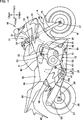
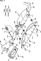
1 zeigt ein rechtes Seitenprofil eines Motorrads, das die vorliegende Erfindung betrifft. 1 shows a right side profile of a motorcycle, which relates to the present invention.
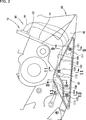
2 zeigt eine vergrößerte Ansicht eines wesentlichen Teils von 1. 2 shows an enlarged view of an essential part of 1 ,
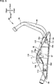
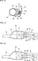
3 zeigt eine Vorderansicht eines Abgassystems, das sich von einem Motor erstreckt. 3 shows a front view of an exhaust system that extends from a motor.
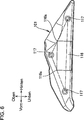
4 stellt eine Installationsstruktur eines Schutzelements dar. 4 represents an installation structure of a protection element.
5 ist ein Profil, das eine Abdeckung einer Katalysatorkammer mit einem dreieckigen Schutzelement darstellt. 5 is a profile that represents a cover of a catalyst chamber with a triangular protective element.
6 zeigt ein Profil des Schutzelements in einer Fahrzeugbreitenrichtung von innen gesehen. 6 shows a profile of the protective element in a vehicle width direction seen from the inside.
7 ist eine perspektivische Explosionsansicht, die die Montage eines Schutzelements und einer Schmuckplatte an dem Abgassystem zeigt. 7 Fig. 13 is an exploded perspective view showing the mounting of a protective member and a jewelry plate on the exhaust system.
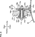
8 zeigt einen Schnitt, der durch die Linie 8-8 in 2 geschnitten ist. 8th shows a section through the line 8-8 in 2 is cut.
9 zeigt einen Schnitt, der durch die Linie 9-9 in 2 geschnitten ist. 9 shows a section through the line 9-9 in 2 is cut.
10 zeigt eine vergrößerte Ansicht eines Bereichs 10 in 9. 10 shows an enlarged view of an area 10 in 9 ,
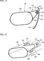
11 zeigt einen Schnitt, der durch die Linie 11-11 in 2 geschnitten ist. 11 shows a section through the line 11-11 in 2 is cut.
12 zeigt eine Perspektivansicht eines oberen Elementhalteteils in 11. 12 shows a perspective view of an upper element holding part in 11 ,
13 zeigt einen Schnitt, der durch die Linie 13-13 in 2 geschnitten ist. 13 shows a section through the line 13-13 in 2 is cut.
14 stellt eine Strömung von Abgas zu der Katalysatorkammer dar. 14 represents a flow of exhaust gas to the catalyst chamber.
15 zeigt eine andere Version einer in 14 gezeigten Ausführungsform. 15 shows a different version of an in 14 shown embodiment.
16 zeigt einen Schnitt eines Auspufftopfs. 16 shows a section of a muffler.
17 zeigt einen Schnitt, der durch die Linie 17-17 in 16 geschnitten ist. 17 shows a section through the line 17-17 in 16 is cut.
18 zeigt einen Schnitt, der durch die Linie 18-18 in 16 geschnitten ist 18 shows a section through the line 18-18 in 16 is cut
19 ist eine perspektivische Explosionsansicht einer Montageposition einer Wärmeabschirmungsplatte in einem Auspufftopf. 19 FIG. 11 is an exploded perspective view of a mounting position of a heat shield plate in a muffler. FIG.
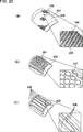
20 stellt eine Oberflächenform der Wärmeabschirmungsplatte in dem Auspufftopf dar. 20 Fig. 10 illustrates a surface shape of the heat shield plate in the muffler.
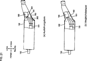
21 stellt Abläufe des Auspufftopfs dar, welche die Ausführungsform und ein Vergleichsbeispiel betreffen. 21 Fig. 3 shows operations of the muffler relating to the embodiment and a comparative example.
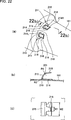
22 stellt einen Halteteil der Schmuckabdeckung dar, die den Auspufftopf teilweise bedeckt. 22 represents a holding part of the jewelry cover, which partially covers the muffler.
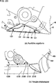
23 stellt Abläufe der Karosserieabdeckung dar, welche die Ausführungsform und das Vergleichsbeispiel betreffen. 23 illustrates drains of the body cover relating to the embodiment and the comparative example.
Ausführungsformen der vorliegenden Erfindung werden nachstehend im Detail beschrieben. In den Zeichnungen und Ausführungsformen beziehen sich „Oben”, „Unten”, „Vorn”, „Hinten”, „Links” und „Rechts” auf die jeweiligen Richtungen, wie sie von einem Fahrer, der auf dem Motorrad fährt, gesehen werden.Embodiments of the present invention will be described below in detail. In the drawings and embodiments, "up", "down", "front", "rear", "left" and "right" refer to the respective directions as seen by a driver riding a motorcycle.
Ausführungsformenembodiments
Zuerst wird eine Ausführungsform der vorliegenden Erfindung unter Bezug auf die Zeichnungen beschrieben.First, an embodiment of the present invention will be described with reference to the drawings.
Wie in 1 gezeigt, ist ein Motorrad 10 ein kleines Fahrzeug, das als Hauptelemente, einen Karosserierahmen 11, einen Motor 12 als eine Brennkraftmaschine, die von dem Karosserierahmen 11 hängt, einen Vorderrad-Lenkabschnitt 14, der drehbar an einem Kopfrohr 21 an dem vorderen Ende des Karosserierahmens montiert ist, eine Hinterradaufhängungseinheit 24, die schwenkbar an einem Schwenkrahmen 23 des Karosserierahmens 11 montiert ist, einen Kraftstoffbehälter 31, der auf der Fahrzeugkarosserie 11 über dem Motor 12 montiert ist, und einen Sitz 32, der auf der Fahrzeugkarosserie 11 hinter dem Kraftstoffbehälter 31 montiert ist, umfasst.As in 1 shown is a motorcycle 10 a small vehicle, as the main elements, a body frame 11 , a motor 12 as an internal combustion engine, that of the body frame 11 hangs, a front wheel steering section 14 which is rotatable on a head pipe 21 is mounted on the front end of the body frame, a rear suspension unit 24 pivoting on a swing frame 23 of the body frame 11 is mounted a fuel tank 31 standing on the vehicle body 11 over the engine 12 is mounted, and a seat 32 standing on the vehicle body 11 behind the fuel tank 31 is mounted, includes.
Der Vorderrad-Lenkabschnitt 14 umfasst eine Lenkwelle 15, eine Lenkstange 19, die an den oberen Teil der Lenkwelle 15 montiert ist, eine Vordergabel 16, die sich von der Lenkwelle 15 nach unten erstreckt, eine Vorderradwelle 17, welche sich in der Fahrzeugbreitenrichtung an dem unteren Ende der Vordergabel 16 erstreckt, und ein Vorderrad 18, das drehbar an der Vorderradwelle 17 montiert ist.The front wheel steering section 14 includes a steering shaft 15 , a handlebar 19 attached to the upper part of the steering shaft 15 is mounted, a front fork 16 extending from the steering shaft 15 extends downwards, a front wheel shaft 17 extending in the vehicle width direction at the lower end of the front fork 16 extends, and a front wheel 18 , which rotates on the front wheel shaft 17 is mounted.
Der Hinterradaufhängungsabschnitt 24 umfasst eine Schwenkwelle 25, welche sich in der Fahrzeugbreitenrichtung auf dem Schwenkrahmen 23 des Karosserierahmens 11 erstreckt, eine Schwinge 26, die sich von der Schwenkwelle 25 in die Richtung hinter dem Fahrzeug erstreckt, eine Hinterradwelle 27, die sich über das hintere Ende der Schwinge 26 erstreckt, ein Hinterrad 28, das an diese Hinterradwelle 27 montiert ist, und eine nicht gezeigte Dämpfungseinheit, die sich zwischen der Schwinge 26 und dem Karosserierahmen 11 erstreckt. The rear suspension section 24 includes a pivot shaft 25 , which extend in the vehicle width direction on the swing frame 23 of the body frame 11 extends, a swingarm 26 extending from the pivot shaft 25 extends in the direction behind the vehicle, a rear wheel shaft 27 extending over the rear end of the swingarm 26 extends, a rear wheel 28 , to this rear wheel shaft 27 is mounted, and a damping unit, not shown, extending between the rocker 26 and the body frame 11 extends.
Als nächstes werden eine Karosserieabdeckung und ähnliches beschrieben. Der Vorderteil des Karosserierahmens 11 ist durch eine vordere Harzverkleidung 41 bedeckt, und der Teil von unterhalb des Kraftstoffbehälters 31 bis unterhalb des Motors 12 und der Vorderteil unterhalb des Sitzes 32 sind von einer mittleren Harzverkleidung 42 bedeckt; von der mittleren Verkleidung 42 fortgesetzt ist der hintere Teil unterhalb des Sitzes 32 von einer hinteren Verkleidung 43 bedeckt. Ein Scheinwerfer 33 ist an dem vorderen Ende der vorderen Verkleidung 41 montiert. Ein Vorderkotflügel 45, um Schmutz von dem Vorderrad 18 fern zu halten, ist an der Vordergabel 16 über dem Vorderrad 18 montiert, und ein hinterer Kotflügel 46, um Schmutz von dem Hinterrad 28 fern zu halten, ist an dem hinteren Ende des Karosserierahmens 11 montiert. Trittbretter 47 und 47 für den Fahrer (nur das Bezugszeichen 47 näher an dem Betrachter ist gezeigt), auf welche der Fahrer von den Fahrgästen seine Füße stellen kann, sind an dem Karosserierahmen 11 montiert, und hinter diesen Trittbrettern 47 und 47 für den Fahrer sind Trittbretter 48 und 48 (nur das Bezugszeichen 48 näher an dem Betrachter ist gezeigt) für den Soziusfahrgast, auf welche der Soziusfahrgast von den Fahrgästen seine Füße stellen kann, über Trittbrettstreben 49 und 49 (nur das Bezugszeichen 49 näher an dem Betrachter ist gezeigt) für den Soziusfahrgast an dem Karosserierahmen 11 montiert.Next, a body cover and the like will be described. The front part of the body frame 11 is through a front resin panel 41 covered, and the part from under the fuel tank 31 to below the engine 12 and the front part below the seat 32 are from a middle resin panel 42 covered; from the middle panel 42 continued is the rear part below the seat 32 from a rear panel 43 covered. A headlight 33 is at the front end of the front panel 41 assembled. A front fender 45 to remove dirt from the front wheel 18 keep away is at the front fork 16 above the front wheel 18 mounted, and a rear fender 46 to remove dirt from the rear wheel 28 Keep away is at the rear end of the body frame 11 assembled. footboards 47 and 47 for the driver (only the reference number 47 closer to the viewer is shown) on which the driver of the passengers can put his feet are on the body frame 11 mounted, and behind these running boards 47 and 47 for the driver are running boards 48 and 48 (only the reference number 48 closer to the viewer is shown) for the passenger passenger, on which the passenger passenger of the passengers can put his feet on footboard struts 49 and 49 (only the reference number 49 closer to the viewer is shown) for the passenger passenger on the body frame 11 assembled.
Der Motor 12 ist ein Viertakt-Zweizylindermotor, dessen Kurbelwelle sich in der Fahrzeugbreitenrichtung erstreckt. Der Motor 12 umfasst ein Kurbelgehäuse 51 und einen Zylinderteil 52, der sich von dem Kurbelgehäuse 51 nach vorn in die Richtung schräg über dem Fahrzeug erstreckt; eine Ansaugvorrichtung 60 ist an der Rückwand 53 des Zylinderteils 52 montiert; und ein Abgasrohr 91 eines Abgassystems ist mit der Vorderwand 54 des Zylinderteils 52 verbunden.The motor 12 is a four-stroke two-cylinder engine whose crankshaft extends in the vehicle width direction. The motor 12 includes a crankcase 51 and a cylinder part 52 that is different from the crankcase 51 extends forward in the direction obliquely above the vehicle; a suction device 60 is on the back wall 53 of the cylinder part 52 assembled; and an exhaust pipe 91 an exhaust system is with the front wall 54 of the cylinder part 52 connected.
Ein Abgassystem 90 umfasst das Abgasrohr 91, die sich von dem Motor 12 erstreckt, eine Katalysatorkammer 92, die auf halbem Weg in dem Abgasrohr 91 eingefügt ist, um Abgas zu reinigen, und einen Auspufftopf 93, der mit dem hinteren Ende des Abgasrohrs 91 verbunden ist. Der Auspufftopf 93 ist an der Trittbrettstrebe 49 des Soziusfahrgasts auf der rechten Seite montiert. Die Katalysatorkammer 92 ist von einem metallischen Schutzelement 101 bedeckt. Ferner ist der vordere Teil des Auspufftopfs 93 durch eine metallische Schmuckabdeckung 102 bedeckt.An exhaust system 90 includes the exhaust pipe 91 that differ from the engine 12 extends, a catalyst chamber 92 that's halfway in the exhaust pipe 91 is inserted to purify exhaust gas and a muffler 93 , with the rear end of the exhaust pipe 91 connected is. The muffler 93 is on the footboard strut 49 of the passenger car mounted on the right side. The catalyst chamber 92 is of a metallic protective element 101 covered. Further, the front part of the muffler 93 through a metallic jewelry cover 102 covered.
Wie in 2 gezeigt, ist die Katalysatorkammer 92, die das Abgassystem 90 unter dem Motor 12 bildet, von dem Schutzelement 101 bedeckt. Das Schutzelement 101 hat eine kontinuierliche Fläche 103, die zu der mittleren Verkleidung 42 als einem Bestandteilelement einer Karosserieabdeckung 40 kontinuierlich ist. Das Schutzelement 101 ist in einer tafelförmigen Form ausgebildet und teilweise mit einer Vertiefung 104 ausgebildet. Es ist derart aufgebaut, dass das Schutzelement 101 und die mittlere Verkleidung 42 miteinander zusammenwirkend die Außenfläche des Fahrzeugs bilden. Die Karosserieabdeckung 40, welche die mittlere Verkleidung 42 umfasst, ist aus Kunstharz ausgebildet, und das Schutzelement 101 ist aus Metall (z. B. einem Stahlblech) geformt.As in 2 shown is the catalyst chamber 92 that the exhaust system 90 under the engine 12 forms, of the protective element 101 covered. The protective element 101 has a continuous surface 103 leading to the middle panel 42 as a constituent element of a body cover 40 is continuous. The protective element 101 is formed in a tabular shape and partially with a recess 104 educated. It is constructed such that the protective element 101 and the middle panel 42 cooperate with each other to form the outer surface of the vehicle. The body cover 40 which the middle panel 42 is formed of synthetic resin, and the protective element 101 is formed of metal (eg a steel sheet).
Als nächstes werden die Anordnung und andere Aspekte von strömungsaufwärtigen Leitungen und der Katalysatorkammer, welche die strömungsaufwärtige Seite des Abgassystems bilden, beschrieben.Next, the arrangement and other aspects of upstream conduits and the catalyst chamber forming the upstream side of the exhaust system will be described.
Wie in 3 gezeigt, erstrecken sich zwei Abgasrohre (strömungsaufwärtige Abgasrohre 95) von der Vorderwand 54 des Zylinderteils, und die zwei strömungsaufwärtigen Abgasrohre 95 sind mit der Katalysatorkammer 92 gekoppelt.As in 3 shown, two exhaust pipes extend (upstream exhaust pipes 95 ) from the front wall 54 of the cylinder part, and the two upstream exhaust pipes 95 are with the catalyst chamber 92 coupled.
In dem unteren Teil des Kurbelgehäuses 51, das die Kurbelwelle des Motors 12 aufnimmt, ist eine Ölwanne 50 angeordnet, die einen Ölsumpf bildet. Die Ölwanne 50 ist in der Fahrzeugbreitenrichtung relativ zu einer Mittellinie C in der Fahrzeugbreitenrichtung links angeordnet, und die Katalysatorkammer 92 ist in der Fahrzeugbreitenrichtung rechts angeordnet. Die Ölwanne 50 ist in der Breitenrichtung des Fahrzeugs links angeordnet, die Katalysatorkammer 92 ist angeordnet, um innerhalb der Breite W des Kurbelgehäuses 51 aufgenommen zu werden, und der untere Teil 92b der Katalysatorkammer 92 wird dazu gebracht, im Wesentlichen mit der unteren Fläche 50a der Ölwanne 50 zusammen zu fallen. Da die Katalysatorkammer 92 ferner derart angeordnet ist, dass sie entlang einer Außenfläche 50b der Ölwanne und der unteren Fläche 51a des Kurbelgehäuses verläuft, kann der Aufbau um die Ölwanne 50 herum kompakt gemacht werden.In the lower part of the crankcase 51 that is the crankshaft of the engine 12 is an oil pan 50 arranged, which forms an oil sump. The oil pan 50 is disposed on the left in the vehicle width direction relative to a center line C in the vehicle width direction, and the catalyst chamber 92 is arranged on the right in the vehicle width direction. The oil pan 50 is located on the left in the width direction of the vehicle, the catalyst chamber 92 is arranged to be within the width W of the crankcase 51 to be included, and the lower part 92b the catalyst chamber 92 is brought to essentially the bottom surface 50a the oil pan 50 to fall together. As the catalyst chamber 92 is further arranged such that it along an outer surface 50b the oil pan and the bottom surface 51a the crankcase runs, the structure around the oil pan 50 be made compact around.
Wie in 4 gezeigt, ist die vordere Hälfte des Abgassystems 90 aus den strömungsaufwärtigen Abgasrohren 95 und 95 aufgebaut, die sich im Wesentlichen von dem Motor (3, Bezugszeichen 12) nach unten erstrecken, und mit dem strömungsaufwärtigen Ende der Katalysatorkammer 92 verbunden, wobei die gehäuseförmige Katalysatorkammer 92 eine eingebaute Katalysatoreinheit (5, Bezugszeichnen 97), die mit den hinteren Enden dieser strömungsaufwärtigen Abgasrohre 95 und 95 verbunden ist und Abgas reinigt, und ein strömungsabwärtiges Abgasrohr 96, das sich von dem hinteren Ende der Katalysatorkammer 92 in Richtung des hinteren Teils des Fahrzeugs erstreckt, hat. Das vorstehend erwähnte Schutzelement 101 ist an der Katalysatorkammer 92 des Abgassystems 90 montiert.As in 4 shown is the front half of the exhaust system 90 from the upstream exhaust pipes 95 and 95 built up essentially from the engine ( 3 , Reference number 12 ) and with the upstream end of the catalyst chamber 92 connected, wherein the housing-shaped catalyst chamber 92 a built-in catalyst unit ( 5 , Reference drawing 97 ), with the rear ends of these upstream exhaust pipes 95 and 95 is connected and purifies exhaust gas, and a downstream exhaust pipe 96 extending from the rear end of the catalyst chamber 92 extends in the direction of the rear part of the vehicle has. The protective element mentioned above 101 is at the catalyst chamber 92 the exhaust system 90 assembled.
Wie in 5 gezeigt, ist die Katalysatorkammer 92 des Abgassystems 90 an einem Element 119 auf der Seite des Karosserierahmens montiert, wobei eine Montagestrebe 106 von dem oberen Ende der Katalysatorkammer 92 nach oben vorsteht. Als nächstes wird das Schutzelement 101 an eine erste Haltestrebe 111, die mit dem vorderen Teil der Katalysatorkammer 92 verbunden ist, eine zweite Haltestrebe 112, die mit dem hinteren Teil der Katalysatorkammer 92 verbunden ist, und eine dritte Haltestrebe 113, die mit dem strömungsabwärtigen Abgasrohr 96 verbunden ist, montiert.As in 5 shown is the catalyst chamber 92 the exhaust system 90 on an element 119 mounted on the side of the body frame, with a mounting strut 106 from the top of the catalyst chamber 92 protrudes upward. Next, the protective element 101 to a first support strut 111 connected to the front part of the catalyst chamber 92 connected, a second support strut 112 connected to the back of the catalyst chamber 92 connected, and a third holding strut 113 connected to the downstream exhaust pipe 96 connected, mounted.
Eine Sensorkomponente 115 ist an dem oberen Teil der Katalysatorkammer 92 montiert. Das Schutzelement 101 ist ausgebildet, um die Sensorkomponente 115 zusammen mit der Katalysatorkammer 92 zu bedecken. Nämlich sind die Katalysatorkammer 92 und die Sensorkomponente 115 durch das Schutzelement 101 bedeckt. Da keine getrennte dedizierte Komponente erforderlich ist, um die Sensorkomponente 115 zu bedecken, kann eine Zunahme der Anzahl von Komponenten unterdrückt werden.A sensor component 115 is at the top of the catalyst chamber 92 assembled. The protective element 101 is designed to be the sensor component 115 together with the catalyst chamber 92 to cover. Namely, the catalyst chamber 92 and the sensor component 115 through the protective element 101 covered. Because no separate dedicated component is required to control the sensor component 115 To cover, an increase in the number of components can be suppressed.
Als nächstes werden Folienelemente beschrieben, die an der hinteren Fläche des Schutzelements haften.Next, sheet members adhered to the back surface of the protective member will be described.
Wie in 6 gezeigt, haftet in der Fahrzeugbreitenrichtung von innen gesehen an der Rückseite des Schutzelements 101 ein rechteckiges metallisches Folienelement 116. Das Folienelement 116 haftet derart an dem Schutzelement 101, dass seine linken und rechten Ecken 116s und 116s jeweils auf einer Linie L1, welche die Mitten der Löcher 117 und 117 verbindet, in denen eine erste Befestigungsschraube (7, Bezugszeichen 121) und eine zweite Befestigungsschraube (7, Bezugszeichen 122) befestigt sind, und auf einer Linie L2, welche die Mitten der Löcher 117 und 117 verbindet, in denen die zweite Schraube 122 und eine dritte Befestigungsschraube (7, Bezugszeichen 123) befestigt sind, positioniert sind. Da das metallische Folienelement 116 an dem Schutzelement 101 haftet, kann die Oberflächensteifheit des Schutzelements 101 erhöht werden, um dadurch die Vibration des Schutzelements 101 zu verringern.As in 6 shown in the vehicle width direction, as seen from the inside adheres to the back of the protective element 101 a rectangular metallic foil element 116 , The foil element 116 thus adheres to the protective element 101 that its left and right corners 116s and 116s each on a line L1, which are the centers of the holes 117 and 117 connects in which a first fixing screw ( 7 , Reference number 121 ) and a second fastening screw ( 7 , Reference number 122 ), and on a line L2, which are the centers of the holes 117 and 117 connects, in which the second screw 122 and a third fixing screw ( 7 , Reference number 123 ) are positioned. As the metallic foil element 116 on the protective element 101 adheres, the surface rigidity of the protective element 101 be increased, thereby the vibration of the protective element 101 to reduce.
In den folgenden 7 bis 11 werden Haltestrukturen und andere Aspekte der Katalysatorkammer und des Schutzelements beschrieben.In the following 7 to 11 For example, support structures and other aspects of the catalyst chamber and the protective element will be described.
Wie in 7 gezeigt, wird die Montagestrebe 106 derart auf der Katalysatorkammer 92 angeordnet, dass sie nach oben vorsteht, und die Montagestrebe 106 wird durch einen Katalysatorfixierbolzen 118 an einem Element auf einer Seite des Karosserierahmens (5, Bezugszeichen 119) montiert. Als nächstes wird das Schutzelement 101 mit der ersten Schraube 121 an die erste Haltestrebe 111, mit der zweiten Schraube 122 an die zweite Haltestrebe 112 und mit der dritten Schraube 123 an die dritte Haltestrebe 113 montiert. Zwischen dem Schutzelement 101 und den ersten bis dritten Haltestreben 111, 112 und 113 sind elastische Elemente 129 eingefügt, und das Schutzelement 101 ist gummigelagert.As in 7 shown is the mounting strut 106 such on the catalyst chamber 92 arranged so that it protrudes upward, and the mounting strut 106 is through a catalyst fixing bolt 118 on an element on one side of the body frame ( 5 , Reference number 119 ) assembled. Next, the protective element 101 with the first screw 121 to the first support strut 111 , with the second screw 122 to the second support strut 112 and with the third screw 123 to the third support strut 113 assembled. Between the protective element 101 and the first to third stops 111 . 112 and 113 are elastic elements 129 inserted, and the protective element 101 is rubber-stored.
Der Auspufftopf 93 ist mit einem Befestigungsteil 125 zum Montieren der Schmuckabdeckung 102 versehen, und die Schmuckabdeckung 102 ist mit einer vierten Schraube 124 an dem Befestigungsteil 125 befestigt. Hinter dem Befestigungsteil 125 ist ein Arretierteil 126 für die Schmuckabdeckung mit dem Auspufftopf 93 verbunden, und Eingreifteile 217 der Schmuckabdeckung sind derart angeordnet, dass sie fähig sind, mit dem Arretierteil 126 für die Schmuckabdeckung einzugreifen.The muffler 93 is with a fixing part 125 to mount the jewelry cover 102 provided, and the jewelry cover 102 is with a fourth screw 124 on the fastening part 125 attached. Behind the fastening part 125 is a locking part 126 for the jewelry cover with the muffler 93 connected, and engaging parts 217 the jewelry cover are arranged so as to be capable of locking with the lock 126 to intervene for the jewelry cover.
Als nächstes wird die Haltestruktur für die Katalysatorkammer, die das Abgassystem bildet, beschrieben.Next, the support structure for the catalyst chamber constituting the exhaust system will be described.
Wie in 8 gezeigt, wird die Montagestrebe 106, die mit der Katalysatorkammer 92 verbunden werden soll, gebildet, indem die die jeweiligen hinteren Flächen eines inneren Elements 107 und eines äußeren Elements 108, die von dem Hinterteil des Fahrzeugs gesehen jeweils im Wesentlichen L-förmig sind, aneinander stoßen. Das innere Element 107 besteht aus einem Schenkelteil 107a und einem vertikalen Teil 107b, der sich von dem Schenkelteil 107a nach oben erstreckt. Ebenso besteht das äußere Element 108 aus einem Schenkelteil 108a und einem vertikalen Teil 108b. Da R-Teile 109 und 109 jeweils mit einem Radius R sich sanft über den Zwischenraum zwischen den Schenkelteilen 107a und 108a und zwischen den vertikalen Teilen 107b und 108b erstrecken, kann die Belastungskonzentration auf den R-Teilen 109 und 109 vermieden werden.As in 8th shown is the mounting strut 106 connected to the catalyst chamber 92 should be connected, formed by the the respective rear surfaces of an inner element 107 and an outer element 108 which are each substantially L-shaped when viewed from the rear of the vehicle, abut each other. The inner element 107 consists of a leg part 107a and a vertical part 107b that is from the leg part 107a extends upwards. Likewise, there is the outer element 108 from a leg part 108a and a vertical part 108b , There R parts 109 and 109 each with a radius R gently over the gap between the leg parts 107a and 108a and between the vertical parts 107b and 108b can extend the stress concentration on the R parts 109 and 109 be avoided.
Eine Schweißmutter 110a wird mit einer Innenfläche 106b der Montagestrebe 106 verbunden, und die Katalysatorkammer 92 des Abgassystems 90 wird durch Ausrichten eines Lochteils 117 des Elements 119 auf der Seite des Karosserierahmens mit einer Außenfläche 106a der Montagestrebe 106 in einer Position, die mit der Schweißmutter 110a übereinstimmt, und unter Verwenden des Katalysatorfixierbolzens 118 an ein Element 119 auf der Seite des Karosserierahmens montiert.A welding nut 110a comes with an inner surface 106b the mounting strut 106 connected, and the catalyst chamber 92 the exhaust system 90 is done by aligning a hole part 117 of the element 119 on the side of the body frame with an outer surface 106a the mounting strut 106 in a position with the welding nut 110a matches and using the Katalysatorfixierbolzens 118 to an element 119 mounted on the side of the body frame.
Als nächstes wird eine gummigelagerte Haltestruktur für die Katalysatorkammer 92 beschrieben. Eine Muffe 128 wird um den Wellenteil 118J des Katalysatorfixierbolzens 118 herum eingefügt, wobei der mit der Muffe 128 integrierte Katalysatorfixierbolzen 118 in elastische Elemente 127 und 127 eingesetzt wird, die im Voraus in den Lochteil 117 des Elements 119 auf der Seite des Karosserierahmens eingepasst sind, und der Katalysatorfixierbolzen 118 wird an der Schweißmutter 110a befestigt, um auf der Seite der Montagestrebe 106 fixiert zu sein. Da die Katalysatorkammer 92 nämlich gummigelagert ist, wird es schwer gemacht, dass die Vibration der Katalysatorkammer 92 auf das Element auf der Seite des Karosserierahmens übertragen wird, gleichzeitig wird es schwierig gemacht, dass die Vibration des Elements 119 auf der Seite des Karosserierahmens auf die Katalysatorkammer 92 übertragen wird.Next, a rubber-bearing support structure for the catalyst chamber 92 described. A sleeve 128 gets around the shaft part 118J the catalyst fixing bolt 118 inserted around, with the sleeve 128 integrated catalyst fixing bolts 118 in elastic elements 127 and 127 is inserted in advance in the hole part 117 of the element 119 are fitted on the side of the body frame, and the catalyst fixing bolt 118 gets at the weld nut 110a attached to the side of the mounting strut 106 to be fixated. As the catalyst chamber 92 namely, rubber-bearing, it is made difficult that the vibration of the catalyst chamber 92 is transferred to the element on the side of the body frame, at the same time it is difficult to make the vibration of the element 119 on the side of the body frame on the catalyst chamber 92 is transmitted.
In den folgenden 9 bis 13 werden die Haltestruktur und andere Aspekte des Schutzelements im Detail beschrieben.In the following 9 to 13 For example, the support structure and other aspects of the protection element will be described in detail.
Wie in 9 gezeigt, stößt die erste Haltestrebe 111 an einer unteren Fläche 131 und einer Außenfläche 132 der Katalysatorkammer 92 an und ist gleichzeitig mit diesen verbunden. Und das Schutzelement 101 stößt an eine Auflagefläche 133 der ersten Haltestrebe 111 an, und das Schutzelement 101 ist über die erste Schraube 121 und eine Schweißmutter 110b an die erste Haltestrebe 111 montiert.As in 9 shown pushes the first holding strut 111 on a lower surface 131 and an outer surface 132 the catalyst chamber 92 and is connected to them at the same time. And the protective element 101 abuts a support surface 133 the first holding strut 111 on, and the protective element 101 is about the first screw 121 and a welding nut 110b to the first support strut 111 assembled.
Da die Katalysatorkammer 92 derart angeordnet ist, dass das Äußere eines länglichen Teils 134 sich von der Rückseite des Fahrzeugs aus gesehen um einen Winkel θ nach oben neigt, kann der Querneigungswinkel des Fahrzeugs relativ zu der Horizontalebene basierend auf der Mitte 134J des länglichen Teils 134 mit dem länglichen Schnitt ohne weiteres sichergestellt werden. Unter Bezug auf die nächste Zeichnung wird die gummigelagerte Struktur der Katalysatorkammer 92 beschrieben.As the catalyst chamber 92 is arranged such that the exterior of an elongate member 134 As seen from the rear of the vehicle, it may tilt upwards at an angle θ, the bank angle of the vehicle relative to the horizontal plane may be based on the center 134J of the elongated part 134 be ensured with the elongated cut easily. Referring to the next drawing, the rubber-bearing structure of the catalyst chamber becomes 92 described.
Wie in 10 gezeigt, ist die perforierte Vertiefung 104, die einen schalenartigen Abschnitt darstellt und die den gesamten Teil 117, in dem die erste Schraube 121 befestigt werden soll, hat, in dem Schutzelement 101 ausgebildet, und die elastischen Elemente 129 und die Muffe 128 werden in die perforierte Vertiefung 104 eingepasst, und das Schutzelement 101 wird mit der ersten Schraube 121 und der Schweißmutter 110b an die erste Haltestrebe 111 montiert. Beachten Sie, dass die Installationsstrukturen der zweiten Haltestrebe und der dritten Haltestrebe, die später beschrieben werden, gummigelagerte Halterungen mit der gleichen Struktur wie vorstehend beschrieben sind und ihre Beschreibung daher weggelassen wird.As in 10 shown is the perforated recess 104 which represents a shell-like section and which covers the entire part 117 in which the first screw 121 should be attached, in the protective element 101 formed, and the elastic elements 129 and the sleeve 128 be in the perforated recess 104 fitted, and the protective element 101 comes with the first screw 121 and the welding nut 110b to the first support strut 111 assembled. Note that the installation structures of the second support strut and the third support strut, which will be described later, are rubber-mounted mounts having the same structure as described above, and description thereof will be omitted.
Wie in 11 gezeigt, stößt die zweite Haltestrebe 112 an einer Deckenfläche 130 und der Außenfläche 132 der Katalysatorkammer 92 an und ist gleichzeitig mit diesen verbunden. Die zweite Haltestrebe 112 weist auf: einen ersten Ausdehnungsteil 141, der sich von der Deckenfläche 130 der Katalysatorkammer 92 in Richtung der Außenseite des Fahrzeugs erstreckt, einen vertikalen Teil 142, der sich von dem äußeren Ende des ersten Ausdehnungsteil 141 erstreckt und an dem das Schutzelement 101 montiert ist, und einen zweiten Ausdehnungsteil 143, der sich von dem unteren Ende des vertikalen Teils 142 zu der Außenfläche 132 der Katalysatorkammer 92 erstreckt. Und das Schutzelement 101 stößt auf einer Auflagefläche 144 an, die einen Teil des vertikalen Teils 142 der zweiten Haltestrebe 112 bildet, und das Schutzelement 101 ist über die zweite Schraube 122 und die Schweißmutter 110c an die zweite Haltestrebe 112 montiert.As in 11 shown pushes the second holding strut 112 on a ceiling surface 130 and the outer surface 132 the catalyst chamber 92 and is connected to them at the same time. The second holding strut 112 indicates: a first extension part 141 that is from the ceiling area 130 the catalyst chamber 92 extends in the direction of the outside of the vehicle, a vertical part 142 extending from the outer end of the first expansion part 141 extends and on which the protective element 101 is mounted, and a second expansion part 143 extending from the lower end of the vertical part 142 to the outer surface 132 the catalyst chamber 92 extends. And the protective element 101 bumps on a support surface 144 on, which is part of the vertical part 142 the second holding strut 112 forms, and the protective element 101 is about the second screw 122 and the welding nut 110c to the second holding strut 112 assembled.
Wie in 12 gezeigt, haben die Enden des ersten Ausdehnungsteils 141 und des zweiten Ausdehnungsteils 143, die jeweils mit der Katalysatorkammer 92 verbunden sind, einen ersten vorstehenden Teil 147 und einen zweiten vorstehenden Teil 148, die sich jeweils in einer axialen Längsrichtung der Katalysatorkammer 92 längs erstrecken, und dieser ersten vorstehende Teil 147 und zweite vorstehenden Teil 148 bilden jeweils einige der Verbindungen 149 und 150. Die Verbindungen 149 und 150 sind durch diesen erste vorstehende Teil 147 und zweite vorstehende Teil 148 verlängert, und die Belastungskonzentration auf den Verbindungen 149 und 150 wird daher vermieden.As in 12 shown have the ends of the first expansion part 141 and the second expansion part 143 , each with the catalyst chamber 92 are connected, a first projecting part 147 and a second protruding part 148 , each in an axial longitudinal direction of the catalyst chamber 92 extend longitudinally, and this first protruding part 147 and second projecting part 148 each form some of the compounds 149 and 150 , The connections 149 and 150 are through this first part above 147 and second part above 148 extended, and the stress concentration on the compounds 149 and 150 is therefore avoided.
Wie in 13 gezeigt, stößt die dritte Haltestrebe 113 an der oberen Fläche 151 und der unteren Seitenfläche 152 der strömungsabwärtigen Abgasleitung 96 an und ist gleichzeitig mit ihnen verbunden. Die dritte Haltestrebe 113 besteht aus einem oberen Ausdehnungsteil 153, der sich von der oberen Fläche 151 des strömungsabwärtigen Abgasrohrs in Richtung der Außenseite des Fahrzeugs erstreckt, einem Auflageteil 154, der sich von einem äußeren Ende des oberen Ausdehnungsteils 153 nach unten erstreckt und an dem Schutzelement 101 montiert ist, und einem unteren Ausdehnungsteil 155, der sich von dem unteren Ende des Auflageteils 154 zu der unteren Seitenfläche 152 des strömungsabwärtigen Abgasrohrs 96 erstreckt. Und das Schutzelement 101 stößt auf dem Auflageteil 154 der dritten Haltestrebe 113 an, und das Schutzelement 101 wird über die dritte Schraube 123 und die Schweißmutter 110d an die dritte Haltestrebe 113 montiert.As in 13 shown pushes the third holding strut 113 on the upper surface 151 and the lower side surface 152 the downstream exhaust pipe 96 and is connected to them at the same time. The third support strut 113 consists of an upper extension part 153 that extends from the upper surface 151 of the downstream exhaust pipe extends toward the outside of the vehicle, a rest part 154 extending from an outer end of the upper expansion part 153 extends downwards and on the protective element 101 is mounted, and a lower extension part 155 extending from the lower end of the support part 154 to the lower side surface 152 of the downstream exhaust pipe 96 extends. And the protective element 101 pushes on the support part 154 the third holding strut 113 on, and the protective element 101 is about the third screw 123 and the welding nut 110d to the third support strut 113 assembled.
Hier wird ein Radius R2 des Abschnitts zwischen dem Auflageteil 154 und dem unteren Ausdehnungsteil 155 größer als der herkömmliche Radius Rb (Rb < R2) festgelegt, und die Länge des unteren Ausdehnungsteils 155, der sich zu der unteren Seitenfläche 152 des strömungsabwärtigen Abgasrohrs 96 erstreckt, wird vergrößert, indem der Raum zwischen dem Auflageteil 154 und dem unteren Ausdehnungsteil 155 mit einem R2-Abschnitt 156 mit einem Radius R2 sanft überspannt wird. Durch Verlängern und Ausdehnen des unteren Teils 155 in dieser Weise, so dass seine Länge im Wesentlichen gleich der des oberen Ausdehnungsteils 153 ist, ist es möglich, es schwerer als bei einer herkömmlichen dritten Haltestrebe (in dem Diagramm durch eine Phantomlinie dargestellt) zu machen, dass die Last auf die dritte Haltestrebe 113 ungleichmäßig wird.Here is a radius R2 of the section between the support part 154 and the bottom one expansion part 155 larger than the conventional radius Rb (Rb <R2), and the length of the lower extension part 155 that goes to the lower side surface 152 of the downstream exhaust pipe 96 extends is increased by the space between the support part 154 and the lower extension part 155 with an R2 section 156 with a radius R2 is gently spanned. By extending and expanding the lower part 155 in this way, so that its length is substantially equal to that of the upper expansion part 153 it is possible to make it heavier than a conventional third holding strut (represented in the diagram by a phantom line) that puts the load on the third strut 113 becomes uneven.
Als nächstes wird das Vorhergehende zusammengefasst. In 5 und 7 hat das Abgassystem 90 eine Katalysatorkammer 92, welche die Katalysatoreinheit 97 darin enthält, und das Schutzelement 101 wird von dem oberen Teil 92a und dem unteren Teil 92b der Katalysatorkammer 92 gehalten. Ferner hat das Abgassystem 90 die strömungsaufwärtigen Abgasrohre 95 und 95, die mit dem vorderen Ende 92c der Katalysatorkammer 92 verbunden sind, und das strömungsabwärtige Abgasrohr 96, das mit dem hinteren Ende 92d der Katalysatorkammer 92 verbunden ist, und außerdem wird das Schutzelement 101 auch von der dritten Haltestrebe 113 des strömungsabwärtigen Abgasrohrs 96 gehalten.Next, the preceding is summarized. In 5 and 7 has the exhaust system 90 a catalyst chamber 92 which the catalyst unit 97 contained therein, and the protective element 101 is from the top part 92a and the lower part 92b the catalyst chamber 92 held. Furthermore, the exhaust system has 90 the upstream exhaust pipes 95 and 95 that with the front end 92c the catalyst chamber 92 are connected, and the downstream exhaust pipe 96 that with the back end 92d the catalyst chamber 92 is connected, and also the protective element 101 also from the third support strut 113 of the downstream exhaust pipe 96 held.
Da das Schutzelement 101 in zwei oberen und unteren Positionen der Katalysatorkammer 92 gehalten wird, kann die Montagesteifheit des Schutzelements 101, insbesondere gegen die Oben-Unten-Vibration, erhöht werden. Außerdem wird der hintere Teil des Schutzelements 101, daneben, dass es von dem oberen Teil 92a und dem unteren Teil 92b der Katalysatorkammer gehalten wird, von dem strömungsabwärtigen Abgasrohr 96 gehalten. Außerdem wird der vordere Teil oder der hintere Teil des Schutzelements 101 gegen die Oben-Unten-Vibration, die auf das Abgassystem 90 angewendet wird, mit dem Ergebnis gehalten, dass die Montagesteifheit des Abgassystems 90 ebenfalls gegen die Schwingung des Fahrzeugs in der Breitenrichtung zur Zeit des zur Zeit des Wendens (Laufabweichung) erhöht werden kann.Because the protective element 101 in two upper and lower positions of the catalyst chamber 92 is held, the mounting rigidity of the protective element 101 , especially against the top-bottom vibration. In addition, the rear part of the protective element 101 , besides, that it from the upper part 92a and the lower part 92b the catalyst chamber is held by the downstream exhaust pipe 96 held. In addition, the front part or the rear part of the protective element 101 against the top-down vibration on the exhaust system 90 is applied, with the result that the mounting rigidity of the exhaust system 90 can also be increased against the vibration of the vehicle in the width direction at the time of turning at the time (running deviation).
Obwohl das Schutzelement von dem strömungsabwärtigen Abgasrohr gehalten wird, kann es im Übrigen ebenso von dem strömungsaufwärtigen Abgasrohr oder sowohl von dem strömungsaufwärtigen Abgasrohr als auch dem strömungsabwärtigen Abgasrohr gehalten werden.Incidentally, although the protective member is held by the downstream exhaust pipe, it may also be held by the upstream exhaust pipe or both the upstream exhaust pipe and the downstream exhaust pipe.
Das Schutzelement 101 ist zu einer im Wesentlichen dreieckigen Form ausgebildet, um die gesamte Katalysatorkammer 92 zu bedecken. Die Katalysatorkammer 92 ist in der Mitte des im Wesentlichen dreieckigen Schutzelements 101 angeordnet, so dass die Katalysatorkammer 92 in einer Position gehalten wird, die nahe an dem Gipfel des im Wesentlichen dreieckigen Schutzelements 101 ist. Neben dem Bedecken der gesamten Katalysatorkammer 92 mit dem im Wesentlichen dreieckigen Schutzelement 101 kann das Schutzelement 101 von der Katalysatorkammer 92 sicher gehalten werden.The protective element 101 is formed into a substantially triangular shape around the entire catalyst chamber 92 to cover. The catalyst chamber 92 is in the middle of the substantially triangular protective element 101 arranged so that the catalyst chamber 92 is held in a position close to the top of the substantially triangular protective element 101 is. In addition to covering the entire catalyst chamber 92 with the substantially triangular protective element 101 can the protective element 101 from the catalyst chamber 92 be kept safe.
In den folgenden 14 bis 15 wird das strömungsabwärtige Ende des strömungsaufwärtigen Abgasrohrs beschrieben.In the following 14 to 15 For example, the downstream end of the upstream exhaust pipe will be described.
Wie in 14 gezeigt, sind die Achsen 98 und 98 an den strömungsabwärtigen Enden 105 und 105 der strömungsaufwärtigen Abgasrohre 95 und 95 einer Grundrissansicht um einen Winkel α relativ zu der Richtung der Längsachse 94 der Katalysatorkammer 92 geneigt. Das heißt, da die Richtung der strömungsabwärtigen Enden 105 der strömungsaufwärtigen Abgasrohre 95 um den Winkel α relativ zu der Längsachse 94 der Katalysatorkammer 92 geneigt ist, wird der Bereich, in dem Abgas in Kontakt mit der Katalysatoreinheit 97 kommt, vergrößert, um die Kontaktmenge von Abgas zu erhöhen.As in 14 shown are the axes 98 and 98 at the downstream ends 105 and 105 the upstream exhaust pipes 95 and 95 a plan view through an angle α relative to the direction of the longitudinal axis 94 the catalyst chamber 92 inclined. That is, because the direction of the downstream ends 105 the upstream exhaust pipes 95 by the angle α relative to the longitudinal axis 94 the catalyst chamber 92 is inclined, the area in which exhaust gas is in contact with the catalyst unit 97 comes, increases, to increase the contact amount of exhaust gas.
Wie in 15 gezeigt, besteht der Unterschied zu der in 14 gezeigten Ausführungsform darin, dass zylindrische Muffenelemente 99 und 99 sich zu der Seite der Katalysatoreinheit 97 der strömungsabwärtigen Enden 105 und 105 der strömungsaufwärtigen Abgasrohre erstrecken, aber andere Aspekte des Aufbaus sind die gleichen. Die Muffenelemente 99 und 99 stehen von dem eingangsseitigen Ende der Katalysatorkammer vor.As in 15 shown, the difference exists in the 14 shown embodiment in that cylindrical sleeve elements 99 and 99 to the side of the catalyst unit 97 the downstream ends 105 and 105 the upstream exhaust pipes extend, but other aspects of the construction are the same. The sleeve elements 99 and 99 project from the entrance end of the catalyst chamber.
In 15 stehen die Muffenelemente 99 und 99 in das Innere der Katalysatorkammer 92 vor.In 15 stand the sleeve elements 99 and 99 into the interior of the catalyst chamber 92 in front.
Da in 14 die strömungsabwärtigen Enden 105 und 105 der strömungsaufwärtigen Abgasrohre nicht in das Innere der Katalysatorkammer 92 vorstehen, sind die Unterschiede in dem Abgaszeitablauf zwischen einzelnen Zylindern geeignet, ein Phänomen der wechselseitigen Beeinflussung von Abgasen, die in diesen Abgasrohren 95 und 95 strömen (Abgasinterferenz) heraufzubeschwören.Because in 14 the downstream ends 105 and 105 the upstream exhaust pipes not into the interior of the catalyst chamber 92 are projected, the differences in the exhaust timing between individual cylinders are suitable, a phenomenon of mutual influence of exhaust gases in these exhaust pipes 95 and 95 to conjure up (exhaust gas interference).
Da in dieser Hinsicht die Muffenelemente 99 und 99 in 15, die in Richtung der Katalysatoreinheit 97 vorstehen, in Richtung der strömungsabwärtigen Enden 105 und 105 der strömungsaufwärtigen Abgasrohre vorstehen, kann die Abgasinterferenz beschränkt werden.Because in this regard the sleeve elements 99 and 99 in 15 pointing in the direction of the catalyst unit 97 projecting, towards the downstream ends 105 and 105 protrude upstream exhaust pipes, the exhaust gas interference can be limited.
Als nächstes wird der Auspuffdämpfer, der die strömungsabwärtige Seite des Abgassystems bildet, beschrieben.Next, the exhaust damper constituting the downstream side of the exhaust system will be described.
Wie in 16 beschrieben, hat der Auspufftopf 93 einen konisch geformten konischen Außenzylinder 161, der auf dem strömungsaufwärtigen Ende angeordnet ist, einen Außenzylinder 162, der mit dem hinteren Ende des konischen Außenzylinders 161 verbunden ist, einen Innenzylinder 163, der im Inneren des Außenzylinders 162 gehalten wird, ein erstes Trennelement 164 und ein zweites Trennelement 165, die sich in eine Richtung in einem rechten Winkel zu der Längsachse des Innenzylinders 163 erstrecken und den Innenzylinder 163 unterteilen, und einer hinteren Kappe 166, die den hinteren Endteil des Innenzylinders 163 verschließt. As in 16 described, has the muffler 93 a conically shaped conical outer cylinder 161 located on the upstream end, an outer cylinder 162 , with the rear end of the conical outer cylinder 161 is connected, an inner cylinder 163 inside the outer cylinder 162 is held, a first separator 164 and a second separator 165 extending in a direction at a right angle to the longitudinal axis of the inner cylinder 163 extend and the inner cylinder 163 divide, and a rear cap 166 , which is the rear end part of the inner cylinder 163 closes.
Der Auspufftopf 93, in dem ein durch das erste Trennelement 164 und den konischen Außenzylinder 161 gebildeter Raum in dem vorderen Fahrzeugbereich dazu gebracht wird, als eine erste Kammer 167, ein durch das erste Trennelement 164 und das zweite Trennelement 165 unterteilter Raum als eine zweite Kammer 168 und ein durch das zweite Trennelement 165 und die hintere Kappe 166 unterteilter Raum als eine dritte Kammer 169 zu dienen, hat in dem konischen Außenzylinder 161 ein vorderes Rohr 190, das in die erste Kammer 167 zu der hinteren Innenseite des konischen Außenzylinders 161 vorsteht, ein erstes Rohr 191, das von dem ersten Trennelement 164 und dem zweiten Trennelement 165 gehalten wird und bewirkt, dass Abgas von der ersten Kammer 167 zu der dritten Kammer 169 strömt, ein zweites Rohr 192, das von dem zweiten Trennelement 165 gehalten wird und bewirkt, dass Abgas von der dritten Kammer 169 zu der zweiten Kammer 168 strömt, und ein Endrohr 193, das von dem zweiten Trennelement 165 und der hinteren Kappe 166 gehalten wird und bewirkt, dass Abgas aus der zweiten Kammer 168 nach außen strömt. Ein Umleitungsloch 194 für die Umleitungsverwendung ist im Wesentlichen in den zentralen Teil des Endrohrs 193 in der Längsrichtung gebohrt.The muffler 93 in which one through the first separator 164 and the conical outer cylinder 161 formed space in the front vehicle area, as a first chamber 167 , a through the first separator 164 and the second separator 165 divided room as a second chamber 168 and a through the second separating element 165 and the back cap 166 subdivided space as a third chamber 169 to serve in the conical outer cylinder 161 a front pipe 190 that in the first chamber 167 to the rear inside of the conical outer cylinder 161 protrudes, a first pipe 191 that of the first separator 164 and the second separator 165 is held and causes exhaust gas from the first chamber 167 to the third chamber 169 flows, a second pipe 192 that of the second separator 165 is held and causes exhaust gas from the third chamber 169 to the second chamber 168 flows, and a tailpipe 193 that of the second separator 165 and the rear cap 166 is held and causes exhaust gas from the second chamber 168 flows outward. A detour hole 194 for diversion is essentially in the central part of the tailpipe 193 drilled in the longitudinal direction.
Abgas, das von dem strömungsabwärtigen Abgasrohr 96 in den Auspufftopf 93 strömt, erreicht die erste Kammer 167 nach dem vorderen Rohr 190, und Abgas in der ersten Kammer 167 erreicht die dritte Kammer 169 nach dem ersten Rohr 191, erreicht die zweite Kammer 168 von der dritten Kammer 169 nach dem zweiten Rohr und wird aus der zweiten Kammer 168 nach dem Endrohr 193 abgelassen.Exhaust gas from the downstream exhaust pipe 96 in the muffler 93 flows, reaches the first chamber 167 after the front pipe 190 , and exhaust in the first chamber 167 reaches the third chamber 169 after the first pipe 191 , reaches the second chamber 168 from the third chamber 169 after the second tube and out of the second chamber 168 after the tailpipe 193 drained.
Wie in 17 gezeigt, ist der hintere Endteil 200 des vorderen Rohrs mit einer Vertiefung 201 ausgebildet, die einwärts vertieft ist, um eine im Wesentlichen halbmondförmige Form zu bilden. Die Vertiefung 201 leitet die Strömungsrichtung von Abgas in eine vorgeschriebene Richtung.As in 17 shown is the rear end part 200 of the front tube with a recess 201 formed inwardly recessed to form a substantially crescent shape. The depression 201 directs the flow direction of exhaust gas in a prescribed direction.
Wie in 18 gezeigt, ist eine Wärmeabschirmungsplatte 202 mit einem gebogenen Abschnitt mit dem konischen Außenzylinder 161 verbunden. Diese Wärmeabschirmungsplatte 202 soll vor Auspuffgas, das in den Auspufftopf strömt, schützen, indem sie es davon abhält, direkt auf die Innenwand 160 des konischen Außenzylinders 161 zu treffen. Vielfältige Formen sind für die Anwendung auf die Oberfläche der Wärmeabschirmungsplatte 202 verfügbar. Die Details werden nachstehend beschrieben.As in 18 shown is a heat shield plate 202 with a bent portion with the conical outer cylinder 161 connected. This heat shield plate 202 should protect from exhaust gas flowing into the muffler by keeping it off, directly onto the inner wall 160 the conical outer cylinder 161 hold true. Various shapes are available for application to the surface of the heat shield plate 202 available. The details are described below.
Wie in 19 gezeigt, haftet die Wärmeabschirmungsplatte 202 von einer Seitenfläche 203 zu der unteren Fläche 204 des konischen Außenzylinders 161 an der Innenfläche (oder Innenwand 200) des konischen Außenzylinders 161. Ein Abgas wird durch die an der Innenwand 200 haftende Wärmeabschirmungsplatte 202 davor bewahrt, direkt auf den konischen Außenzylinder 161 zu treffen.As in 19 shown, the heat shield plate adheres 202 from a side surface 203 to the lower surface 204 the conical outer cylinder 161 on the inner surface (or inner wall 200 ) of the conical outer cylinder 161 , An exhaust gas will pass through the on the inner wall 200 adhesive heat shield plate 202 preserved, directly on the conical outer cylinder 161 hold true.
Als nächstes wird die Oberflächenform der Wärmeabschirmungsplatte 202 beschrieben.Next, the surface shape of the heat shield plate 202 described.
Wie in 20(a) gezeigt, ist die Wärmeabschirmungsplatte 202 eine poröse Platte 206 mit vielen Löchern 196 in der Oberfläche. Durch Ausbilden der porösen Platte 206 mit einem derartigen Aufbau, wird es leichter, dass Abgas, das auf die poröse Platte 206 getroffen ist, in der ersten Kammer (16, Bezugszeichen 167) zerstreut wird.As in 20 (a) shown is the heat shield plate 202 a porous plate 206 with many holes 196 in the surface. By forming the porous plate 206 With such a structure, it becomes easier for exhaust gas to be deposited on the porous plate 206 in the first chamber ( 16 , Reference number 167 ) is scattered.
20(b) zeigt eine andere Ausführungsform dessen, was in 20(a) gezeigt ist, und 20(c) noch eine andere Ausführungsform dessen, was in 20(a) gezeigt ist. 20 (b) shows another embodiment of what is in 20 (a) is shown, and 20 (c) Yet another embodiment of what is in 20 (a) is shown.
Wie in 20(b) gezeigt, sind viele im Wesentlichen halbkugelförmige Vorsprünge 207 auf der Oberfläche der Wärmeabschirmungsplatte 202 ausgebildet.As in 20 (b) Many are essentially hemispherical protrusions 207 on the surface of the heat shield plate 202 educated.
Wie in 20(c) gezeigt, können viele vorstehende Bandabschnitte 208, deren Schnitt gebogen bandförmig ist, ebenfalls auf der Oberfläche der Wärmeabschirmungsplatte ausgebildet sein. Durch Ausbilden der Oberfläche der Wärmeabschirmungsplatte 202 zu einer unebenen Form in dieser Weise, wird es leichter gemacht, Abgas, das auf die Wärmeabschirmungsplatte 202 aufgetroffen ist, zu zerstreuen.As in 20 (c) shown, many prominent band sections 208 whose section is curved band-shaped, also be formed on the surface of the heat shield plate. By forming the surface of the heat shield plate 202 To get an uneven shape in this way, it will be easier to put exhaust gas on the heat shield plate 202 has struck, to disperse.
Als nächstes wird die Wirkung der Kombination der Vertiefungen des vorderen Rohrs und der Wärmeabschirmungsplatte beschrieben.Next, the effect of the combination of the recesses of the front tube and the heat shielding plate will be described.
Wie in einem Vergleichsbeispiel von 21(b) gezeigt, trifft ein Teil des Abgases, der das vordere Rohr 190 verlassen hat, in der ersten Kammer direkt auf die Innenwand 160 des konischen Außenzylinders 161. Als ein Ergebnis steigt die Temperatur des konischen Außenzylinders 161, der von dem Hochtemperatur-Abgas getroffen wird, lokal an, was manchmal eine teilweise Entfärbung der Außenwand heraufbeschwört und Raum für Verbesserungen im Aussehen mit sich bringt.As in a comparative example of 21 (b) shown, a part of the exhaust gas that hits the front pipe 190 left in the first chamber directly on the inner wall 160 the conical outer cylinder 161 , As a result, the temperature of the conical outer cylinder increases 161 locally hit by the high temperature exhaust gas, which sometimes causes a partial discoloration of the Enclosed outside wall and room for improvements in appearance.
In dieser Hinsicht ist die vorliegende Erfindung, wie durch eine Ausführungsform von 21(a) gezeigt, in der Strömungsrichtung durch die Vertiefung 201 in dem vorderen Rohr 190 geändert und macht es schwer, in der ersten Kammer direkt auf die Innenwand des konischen Außenzylinders 161 zu treffen. Da außerdem die Wärmeabschirmungsplatte 202 mit vielen Löchern (20, Bezugszeichen 196) in den Oberflächen in einer Region, wo das aus der Mündung des vorderen Rohrs 190 herauskommende Abgas auftrifft, an der Innenwand 160 des konischen Außenzylinders 161 haftet, wird es schwer gemacht, dass Abgas direkt auf die Innenwand 160 des konischen Außenzylinders 161 trifft, und gleichzeitig wird Abgas, das auf den konischen Außenzylinder 161 aufgetroffen ist, durch die Wärmeabschirmungsplatte 202 in einer porösen Plattenform mobilisiert. Daher wird der Temperaturanstieg des konischen Außenzylinders 161 beschränkt, was ermöglicht, dass das Problem der Teilentfärbung der Außenwand gelöst wird.In this regard, the present invention, as by an embodiment of 21 (a) shown in the flow direction through the recess 201 in the front pipe 190 changed and makes it difficult in the first chamber directly on the inner wall of the conical outer cylinder 161 hold true. In addition, because the heat shield plate 202 with many holes ( 20 , Reference number 196 ) in the surfaces in a region where the out of the mouth of the front tube 190 coming out exhaust gas impinges, on the inner wall 160 the conical outer cylinder 161 sticks, it is hard to make that exhaust directly on the inner wall 160 the conical outer cylinder 161 meets, and at the same time becomes exhaust gas, which is on the conical outer cylinder 161 has hit through the heat shield plate 202 mobilized in a porous plate form. Therefore, the temperature rise of the conical outer cylinder 161 limited, which allows the problem of partial discoloration of the outer wall is solved.
Als nächstes wird die Haltestruktur für die Schmuckabdeckung, die an dem konischen Außenzylinder des Auspufftopfs montiert werden soll, beschrieben.Next, the jewelry cover holding structure to be mounted on the conical outer cylinder of the muffler will be described.
22(a) zeigt eine Perspektivansicht eines Schmuckabdeckungshakens, der an den konischen Außenzylinder montiert werden soll, 22(b), 22(b)–(b) und 22(c) einen Grundriss des Schmuckabdeckungshakens. 22 (a) shows a perspective view of a jewelry cover hook to be mounted on the conical outer cylinder, 22 (b) . 22 (b) -(Federation 22 (c) a floor plan of the jewelry cover hook.
Wie in 22(a) gezeigt, umfassen Schmuckabdeckungshaken 211 und 211 Auflageteile 214 und 214, die mit dem konischen Außenzylinder 161 verbunden werden sollen, vertikale Teile 215 und 215, die sich von den Endteilen der Auflageteile 214 und 214 erheben, und Sperrklauen 216 und 216, mit denen Eingreifteile (7, Bezugszeichen 217 und 217) der Schmuckabdeckung, die von den oberen Enden der vertikalen Teile 215 und 215 in Richtung der Auflageteile 214 und 214 geklappt sind, arretiert werden sollen.As in 22 (a) shown include jewelry cover hooks 211 and 211 supporting parts 214 and 214 that with the conical outer cylinder 161 to be connected, vertical parts 215 and 215 extending from the end parts of the support parts 214 and 214 raise, and pawls 216 and 216 with which engaging parts ( 7 , Reference number 217 and 217 ) of the jewelry cover, from the upper ends of the vertical parts 215 and 215 in the direction of the support parts 214 and 214 are folded, to be locked.
Da die zwei Schmuckabdeckungshaken 211 und 211 die gleiche Form haben, wird die folgende Beschreibung stellvertretend nur die Struktur eines Schmuckabdeckungshakens 211 beschreiben.As the two jewelry cover hooks 211 and 211 have the same shape, the following description is representative only the structure of a jewelry cover hook 211 describe.
In 22(c) ist die Breite W1 der Sperrklaue 216 im Vergleich zu der Breite W2 des vertikalen Teil 215 verschmälert (W1 < W2). In 22(a) sind U-förmige Kerben 218 und 218, die in einer U-Form nach innen geschnitten sind, in den linken und rechten Seiten 214L und 214R des Auflageteils 214 ausgebildet, um die Breite des Auflageteils 214 teilweise zu verschmälern, was ermöglicht, dass die Belastungskonzentration in der Nähe des geschweißten Teils vermieden wird.In 22 (c) is the width W1 of the pawl 216 compared to the width W2 of the vertical part 215 narrowed down (W1 <W2). In 22 (a) are U-shaped notches 218 and 218 , which are cut inwards in a U-shape, in the left and right sides 214L and 214R of the support part 214 formed to the width of the support part 214 partially narrow, which allows the stress concentration in the vicinity of the welded part is avoided.
Wie in 22(b) gezeigt, wird der Raum zwischen dem Auflageteil 214 und dem vertikalen Teil 215 durch einen R3-Teil 219 mit einem Radius R3 aufgespannt. Auch wird der Raum zwischen dem vertikalen Teil 215 und der Sperrklaue 216 durch einen R4-Teil 221 mit einem Radius R4 aufgespannt. Indem hier eine Beziehung von R3 < R4 zwischen dem Radius R3 mit dem breiteren R3-Teil 219, der den Raum zwischen dem Auflageteil 214 und dem vertikalen Teil 215 aufspannt, und dem Radius R4 des schmaleren R4-Teils, der den Raum zwischen der Sperrklaue 216 und dem vertikalen Teil 215 aufspannt, wird eine Form mit einem guten Belastungsausgleich ausgebildet. Außerdem wird durch Ausdehnen des Auflageteils 214 und der Sperrklaue 216 in der gleichen Richtung und das Ausbilden des Schmuckabdeckungshakens 211 zu einer U-Form und Biegen desselben in die gleiche Richtung wie vorstehend, der Freiheitsgrad in der Formveränderung vergrößert.As in 22 (b) shown, the space between the support part 214 and the vertical part 215 through an R3 part 219 Spanned with a radius R3. Also, the space between the vertical part 215 and the locking claw 216 through an R4 part 221 Spanned with a radius R4. By here a relationship of R3 <R4 between the radius R3 with the wider R3 part 219 that is the space between the pad part 214 and the vertical part 215 spans, and the radius R4 of the narrower R4 part, the space between the locking claw 216 and the vertical part 215 spans, a shape is formed with a good load balance. In addition, by expanding the support member 214 and the locking claw 216 in the same direction and forming the jewelry cover hook 211 to a U-shape and bending it in the same direction as above, the degree of freedom in the shape change is increased.
Als nächstes werden Ergebnisse des bisher beschriebenen kleinen Fahrzeugs beschrieben.Next, results of the small vehicle described so far will be described.
Wie in einer Ausführungsform von 23(a) gezeigt, hat das Schutzelement 101, das eine seitliche Seite des Abgassystems 90 bedeckt, die kontinuierliche Fläche 103, die zu der Karosserieabdeckung 40 kontinuierlich ist, und dieses Schutzelement 101 und die Karosserieabdeckung 40 bauen zusammenwirkend miteinander die Außenfläche des Fahrzeugs auf.As in one embodiment of 23 (a) shown has the protective element 101 , which is a lateral side of the exhaust system 90 covered, the continuous area 103 leading to the body cover 40 is continuous, and this protective element 101 and the body cover 40 cooperatively build the outer surface of the vehicle together.
Wie andererseits in einem Vergleichsbeispiel von 23(b) gezeigt ist, hat ein Schutzelement 101B, das eine seitliche Seite eines Abgassystems bedeckt, keine kontinuierliche Fläche, die zu einer mittleren Verkleidung 42B, die ein Bestandteilelement einer Karosserieabdeckung 40B ist, kontinuierlich ist. An ihrer Grenze mit dem Schutzelement 101B hat die mittlere Verkleidung 42B eine vordere Öffnung 23B zum Ansaugen der Außenluft und einen Montageteil 232B, der sich zu dem Karosserierahmen erstreckt und an dem die erste Schraube 121B befestigt ist, und die Kopplung zwischen der mittleren Verkleidung 42B und dem Schutzelement 101B lässt in dem ästhetischen Designaspekt Raum für Verbesserungen.On the other hand, in a comparative example of 23 (b) is shown has a protective element 101B that covers a lateral side of an exhaust system, not a continuous surface leading to a central fairing 42B , which is an integral part of a body cover 40B is, is continuous. At its border with the protective element 101B has the middle panel 42B a front opening 23B for sucking in the outside air and a mounting part 232B which extends to the body frame and to which the first screw 121B is attached, and the coupling between the middle panel 42B and the protective element 101B leaves room for improvement in the aesthetic design aspect.
Da gemäß der vorliegenden Ausführungsform wie in einer Ausführungsform von 23(a) das Schutzelement 101 mit der kontinuierlichen Fläche 103 versehen ist, die mit der Karosserieabdeckung 40 kontinuierlich ist, besteht keine Notwendigkeit, die Karosserieabdeckung 40 zu formen, um die seitliche Seite des Abgassystems zu bedecken und zu verbergen. Als ein Ergebnis ist es möglich, das Abgassystem 90 mit dem Schutzelement 101 abzudecken, während der Freiheitsgrad in der Form der Karosserieabdeckung verbessert wird. Da der Freiheitsgrad in der Form der Karosserieabdeckung verbessert wird, kann die Qualität des Aussehens des Fahrzeugs verbessert werden.As according to the present embodiment, as in one embodiment of 23 (a) the protective element 101 with the continuous surface 103 is provided with the body cover 40 is continuous, there is no need to cover the body 40 mold to cover and hide the lateral side of the exhaust system. As a result, it is possible the exhaust system 90 with the protective element 101 while improving the degree of freedom in the form of the body cover. Since the degree of freedom in the shape of the body cover is improved, the quality of the appearance of the vehicle can be improved.
Neben dem, was bemerkt wurde, ist in dem Vergleichsbeispiel von 23(b) das Schutzelement, welches das Abgassystem 90 bedeckt, an dem Karosserierahmen montiert, der in der Fahrzeugbreitenrichtung weiter einwärts als das Abgassystem 90 angeordnet ist. Da ein Teil des Schutzelements, das an den Karosserierahmen montiert ist, in der Fahrzeugbreitenrichtung einwärts ausgedehnt ist, wird der Freiheitsgrad in der Form des Schutzelements in manchen Fällen beschränkt.In addition to what has been noted is in the comparative example of 23 (b) the protective element which the exhaust system 90 covered, mounted on the body frame, in the vehicle width direction further inward than the exhaust system 90 is arranged. Since a part of the protective member mounted on the body frame is inwardly extended in the vehicle width direction, the degree of freedom in the shape of the protective member is limited in some cases.
In dieser Hinsicht ist das Schutzelement 101 gemäß der vorliegenden Erfindung, wie in der Ausführungsform von 23(a) gezeigt, an das Abgassystem 90 montiert, das näher an dem Karosserierahmen 11 positioniert ist. Da das Schutzelement 101 an dem Abgassystem 90 montiert ist, das in engerer Nachbarschaft zu dem Schutzelement 101 als der Karosserierahmen 11 angeordnet ist, besteht für eine derartige Vorrichtung keine Notwendigkeit, den Teil des Schutzelements 101 auszudehnen. Als ein Ergebnis kann der Freiheitgrad in der Form des Schutzelements 101 erhöht werden.In this regard, the protective element 101 according to the present invention, as in the embodiment of 23 (a) shown to the exhaust system 90 mounted closer to the body frame 11 is positioned. Because the protective element 101 at the exhaust system 90 is mounted, in closer proximity to the protective element 101 as the body frame 11 is arranged, there is no need for such a device, the part of the protective element 101 expand. As a result, the degree of freedom in the shape of the protective element 101 increase.
Ferner ist das Schutzelement 101 aus Metall geformt, und wird, wie in 7 gezeigt, über die elastischen Elemente 129 an das Abgassystem 90 montiert. Die elastischen Elemente 129, die zwischen dem Schutzelement 101 und dem Abgassystem 90 eingefügt sind, machen es schwer, dass Vibrationen von dem Abgassystem 90 an die elastischen Elemente 129 übertragen werden und dass das Schutzelement 101 ein Resonanzphänomen in Bezug auf das Abgassystem bewirkt. Die Vertiefungen 104 (Vertiefungen 104a und 104b) sind in dem Schutzelement 101 ausgebildet. Diese Vertiefungen 104a und 104b dienen dazu, die Steifheit des Schutzelements 101 zu erhöhen. Die erhöhte Steifheit des Schutzelements 101 kann das Resonanzphänomen mit der Katalysatorkammer 92 zusätzlich beschränken.Furthermore, the protective element 101 made of metal, and will, as in 7 shown over the elastic elements 129 to the exhaust system 90 assembled. The elastic elements 129 that is between the protective element 101 and the exhaust system 90 are inserted, make it difficult for vibrations from the exhaust system 90 to the elastic elements 129 be transferred and that the protective element 101 causes a resonance phenomenon with respect to the exhaust system. The wells 104 (wells 104a and 104b ) are in the protective element 101 educated. These depressions 104a and 104b serve to increase the stiffness of the protective element 101 to increase. The increased stiffness of the protective element 101 can the resonance phenomenon with the catalyst chamber 92 additionally restrict.
In 1, 5 und 7 ist die Karosserieabdeckung 40 an dem Karosserierahmen 11 montiert, und das Schutzelement 101 ist über die elastischen Elemente 129 an dem Abgassystem 90 montiert. Die Verwendung verschiedener Halteelemente für die Karosserieabdeckung 40 und für das Schutzelement 101 könnte einen Spalt oder ähnliches zur Folge haben, der dadurch, dass Vibrationen oder ähnliches in dem Fahrzeug in einem Verbindungsteil (9, Bezugszeichen 222) zwischen der Fahrzeugkarosserie 40 und dem Schutzelement 101 auftreten, heraufbeschworen wird.In 1 . 5 and 7 is the body cover 40 on the body frame 11 mounted, and the protective element 101 is about the elastic elements 129 at the exhaust system 90 assembled. The use of various body panel retaining elements 40 and for the protective element 101 could result in a gap or the like caused by vibrations or the like in the vehicle in a connecting part (FIG. 9 , Reference number 222 ) between the vehicle body 40 and the protective element 101 occur, is summoned.
Da das Schutzelement 101 gemäß der vorliegenden Erfindung in dieser Hinsicht über die elastischen Elemente 129 an dem Abgassystem 90 montiert ist, ist eine winzige Verschiebung des Schutzelements 101 zulässig. Als ein Ergebnis wird es schwer gemacht, dass ein Spalt oder ähnliches in dem Verbindungsteil 222 zwischen der Karosserieabdeckung 40 und dem Schutzelement 101 auftritt.Because the protective element 101 according to the present invention in this regard via the elastic elements 129 at the exhaust system 90 mounted, is a tiny shift of the protective element 101 allowed. As a result, it is made difficult that a gap or the like in the connecting part 222 between the body cover 40 and the protective element 101 occurs.
Beachten Sie, dass, obwohl die vorliegende Erfindung in ihren Ausführungsformen auf Motorräder angewendet wird, sie auch auf dreirädrige Fahrzeuge angewendet werden kann, und es kein Problem in ihrer Anwendung auf kleine Fahrzeuge im Allgemeinen gibt.Note that although the present invention is applied to motorcycles in its embodiments, it can also be applied to three-wheeled vehicles, and there is no problem in its application to small vehicles in general.
Die vorliegende Erfindung ist für Motorräder geeignet, die mit einer Katalysatorkammer ausgerüstet sind.The present invention is suitable for motorcycles equipped with a catalyst chamber.
BezugszeichenlisteLIST OF REFERENCE NUMBERS
-
1010
-
Kleines Fahrzeug (Motorrad)Small vehicle (motorcycle)
-
1111
-
Karosserierahmenbody frame
-
1212
-
Brennkraftmaschine (Motor)Internal combustion engine (engine)
-
4040
-
Karosserieabdeckungbody cover
-
9090
-
Abgassystemexhaust system
-
9292
-
Katalysatorkammercatalyst chamber
-
9595
-
strömungsaufwärtiges Abgasrohrupstream exhaust pipe
-
9696
-
strömungsabwärtiges Abgasrohrdownstream exhaust pipe
-
101101
-
Schutzelementprotection element
-
103103
-
kontinuierliche Flächecontinuous area
-
104104
-
Vertiefungdeepening
-
1515
-
Sensorkomponentesensor component
-
129129
-
elastisches Elementelastic element