JP4700586B2 - Motorcycle exhaust system - Google Patents
Motorcycle exhaust system Download PDFInfo
- Publication number
- JP4700586B2 JP4700586B2 JP2006274720A JP2006274720A JP4700586B2 JP 4700586 B2 JP4700586 B2 JP 4700586B2 JP 2006274720 A JP2006274720 A JP 2006274720A JP 2006274720 A JP2006274720 A JP 2006274720A JP 4700586 B2 JP4700586 B2 JP 4700586B2
- Authority
- JP
- Japan
- Prior art keywords
- protector
- exhaust
- exhaust muffler
- protector member
- muffler
- Prior art date
- Legal status (The legal status is an assumption and is not a legal conclusion. Google has not performed a legal analysis and makes no representation as to the accuracy of the status listed.)
- Expired - Fee Related
Links
Images


Classifications
-
- B—PERFORMING OPERATIONS; TRANSPORTING
- B62—LAND VEHICLES FOR TRAVELLING OTHERWISE THAN ON RAILS
- B62J—CYCLE SADDLES OR SEATS; AUXILIARY DEVICES OR ACCESSORIES SPECIALLY ADAPTED TO CYCLES AND NOT OTHERWISE PROVIDED FOR, e.g. ARTICLE CARRIERS OR CYCLE PROTECTORS
- B62J23/00—Other protectors specially adapted for cycles
-
- F—MECHANICAL ENGINEERING; LIGHTING; HEATING; WEAPONS; BLASTING
- F01—MACHINES OR ENGINES IN GENERAL; ENGINE PLANTS IN GENERAL; STEAM ENGINES
- F01N—GAS-FLOW SILENCERS OR EXHAUST APPARATUS FOR MACHINES OR ENGINES IN GENERAL; GAS-FLOW SILENCERS OR EXHAUST APPARATUS FOR INTERNAL COMBUSTION ENGINES
- F01N1/00—Silencing apparatus characterised by method of silencing
-
- F—MECHANICAL ENGINEERING; LIGHTING; HEATING; WEAPONS; BLASTING
- F01—MACHINES OR ENGINES IN GENERAL; ENGINE PLANTS IN GENERAL; STEAM ENGINES
- F01N—GAS-FLOW SILENCERS OR EXHAUST APPARATUS FOR MACHINES OR ENGINES IN GENERAL; GAS-FLOW SILENCERS OR EXHAUST APPARATUS FOR INTERNAL COMBUSTION ENGINES
- F01N13/00—Exhaust or silencing apparatus characterised by constructional features ; Exhaust or silencing apparatus, or parts thereof, having pertinent characteristics not provided for in, or of interest apart from, groups F01N1/00 - F01N5/00, F01N9/00, F01N11/00
- F01N13/14—Exhaust or silencing apparatus characterised by constructional features ; Exhaust or silencing apparatus, or parts thereof, having pertinent characteristics not provided for in, or of interest apart from, groups F01N1/00 - F01N5/00, F01N9/00, F01N11/00 having thermal insulation
-
- F—MECHANICAL ENGINEERING; LIGHTING; HEATING; WEAPONS; BLASTING
- F01—MACHINES OR ENGINES IN GENERAL; ENGINE PLANTS IN GENERAL; STEAM ENGINES
- F01N—GAS-FLOW SILENCERS OR EXHAUST APPARATUS FOR MACHINES OR ENGINES IN GENERAL; GAS-FLOW SILENCERS OR EXHAUST APPARATUS FOR INTERNAL COMBUSTION ENGINES
- F01N13/00—Exhaust or silencing apparatus characterised by constructional features ; Exhaust or silencing apparatus, or parts thereof, having pertinent characteristics not provided for in, or of interest apart from, groups F01N1/00 - F01N5/00, F01N9/00, F01N11/00
- F01N13/18—Construction facilitating manufacture, assembly, or disassembly
- F01N13/1805—Fixing exhaust manifolds, exhaust pipes or pipe sections to each other, to engine or to vehicle body
- F01N13/1811—Fixing exhaust manifolds, exhaust pipes or pipe sections to each other, to engine or to vehicle body with means permitting relative movement, e.g. compensation of thermal expansion or vibration
-
- B—PERFORMING OPERATIONS; TRANSPORTING
- B62—LAND VEHICLES FOR TRAVELLING OTHERWISE THAN ON RAILS
- B62K—CYCLES; CYCLE FRAMES; CYCLE STEERING DEVICES; RIDER-OPERATED TERMINAL CONTROLS SPECIALLY ADAPTED FOR CYCLES; CYCLE AXLE SUSPENSIONS; CYCLE SIDE-CARS, FORECARS, OR THE LIKE
- B62K2202/00—Motorised scooters
-
- F—MECHANICAL ENGINEERING; LIGHTING; HEATING; WEAPONS; BLASTING
- F01—MACHINES OR ENGINES IN GENERAL; ENGINE PLANTS IN GENERAL; STEAM ENGINES
- F01N—GAS-FLOW SILENCERS OR EXHAUST APPARATUS FOR MACHINES OR ENGINES IN GENERAL; GAS-FLOW SILENCERS OR EXHAUST APPARATUS FOR INTERNAL COMBUSTION ENGINES
- F01N2260/00—Exhaust treating devices having provisions not otherwise provided for
- F01N2260/20—Exhaust treating devices having provisions not otherwise provided for for heat or sound protection, e.g. using a shield or specially shaped outer surface of exhaust device
-
- F—MECHANICAL ENGINEERING; LIGHTING; HEATING; WEAPONS; BLASTING
- F01—MACHINES OR ENGINES IN GENERAL; ENGINE PLANTS IN GENERAL; STEAM ENGINES
- F01N—GAS-FLOW SILENCERS OR EXHAUST APPARATUS FOR MACHINES OR ENGINES IN GENERAL; GAS-FLOW SILENCERS OR EXHAUST APPARATUS FOR INTERNAL COMBUSTION ENGINES
- F01N2450/00—Methods or apparatus for fitting, inserting or repairing different elements
- F01N2450/24—Methods or apparatus for fitting, inserting or repairing different elements by bolts, screws, rivets or the like
Description
本発明は、エンジン本体のシリンダヘッドから延出される排気管に排気マフラーが接続され、該排気マフラーの上部および外側面がプロテクタで覆われる自動二輪車の排気装置に関する。 The present invention relates to an exhaust system for a motorcycle in which an exhaust muffler is connected to an exhaust pipe extending from a cylinder head of an engine body, and the upper and outer surfaces of the exhaust muffler are covered with a protector.
金属製である単一のプロテクタで排気マフラーの上部が覆われるようにしたものが、特許文献1で知られており、また合成樹脂から成る内外二重のプロテクタ部材で排気マフラーの外側面が覆われるようにしたものが、特許文献2で知られている。
ところが、上記特許文献1で開示されたものでは、プロテクタが金属製であることから走行風によって冷却され易いという利点はあるものの、熱伝導率が高いので、最も高温となる排気マフラーの上部を覆う部分でプロテクタに伝達された熱がプロテクタ全体に広がり易い。また金属表面が排気マフラーの側面全体に広がっていると、排気マフラーの存在感は出るものの、重量感も増してしまい、スポーティなイメージの自動二輪車には外観性がマッチし難いと言う面もある。 However, the one disclosed in Patent Document 1 has an advantage that the protector is made of metal and thus is easily cooled by the traveling wind, but has a high thermal conductivity, and thus covers the upper part of the exhaust muffler that is at the highest temperature. The heat transmitted to the protector at the part tends to spread throughout the protector. In addition, if the metal surface spreads over the entire side of the exhaust muffler, the exhaust muffler's presence will appear, but the weight will also increase, and it may be difficult to match the appearance of a sporty motorcycle .
また上記特許文献2で開示されたものでは、プロテクタを構成する内外二重のプロテクタ部材が合成樹脂製であることから、熱の広がりを抑えることができるものの、蓄熱し易く、走行風によっても冷えにくいと言う課題があり、しかも金属製のものに比べると耐久性を高める必要がある上に、光沢性を得るには塗装などの処理が必要となり、高価なものとなってしまう。 Moreover, in what was disclosed by the said patent document 2, since the inner and outer double protector member which comprises a protector is a product made from a synthetic resin, although it can suppress the spread of a heat | fever, it is easy to store heat and it cools also by driving | running | working wind. In addition, there is a problem that it is difficult, and it is necessary to improve durability as compared with a metal one. In addition, in order to obtain gloss, a treatment such as painting is required, which is expensive.
本発明は、かかる事情に鑑みてなされたものであり、優れた耐久性および外観性を得ることを可能として、排気マフラーからの熱を優れた断熱性で遮断し得るようにした自動二輪車の排気装置を提供することを目的とする。 The present invention has been made in view of such circumstances, and is capable of obtaining excellent durability and appearance, and is capable of obtaining heat from an exhaust muffler so that heat from the exhaust muffler can be shut off with excellent heat insulation. An object is to provide an apparatus.
上記目的を達成するために、請求項1記載の発明は、エンジン本体のシリンダヘッドから延出される排気管に排気マフラーが接続され、該排気マフラーの外側面がプロテクタで覆われる自動二輪車の排気装置において、前記プロテクタが、前記排気マフラーの少なくとも外側面を覆う金属製の第1プロテクタ部材と、第1プロテクタ部材の上部を外部に露出させて第1プロテクタ部材の下部を外側方から覆う合成樹脂製の第2プロテクタ部材とから成り、前記第2プロテクタ部材の上縁は、その上縁の前後両端部よりも中間部が下がった湾曲形状に形成され、前記第2プロテクタ部材には、前記第1プロテクタ部材の上部の露出部に向けて走行風を導く走行風導入口が、その導入口の開口部軸線を前下がりに傾斜させるようにして設けられることを特徴とする。 In order to achieve the above object, according to a first aspect of the present invention, there is provided an exhaust system for a motorcycle in which an exhaust muffler is connected to an exhaust pipe extending from a cylinder head of an engine body, and an outer surface of the exhaust muffler is covered with a protector. The protector is made of a first metal protector member that covers at least the outer surface of the exhaust muffler, and a synthetic resin that exposes the upper portion of the first protector member to the outside and covers the lower portion of the first protector member from the outside. Ri and a second protector member, the upper edge of the second protector member is formed in a curved shape the intermediate portion falls below the front and rear end portions of the upper edge thereof, the second protector member, said first 1 running wind inlet towards the exposed portion of the upper portion of the protector member guiding the running wind is provided so as to tilt the opening axis of the inlet before falling And wherein the door.
また請求項2記載の発明は、請求項1記載の発明の構成に加えて、第1および第2プロテクタ部材が共締めで排気マフラーに支持されることを特徴とする。 According to a second aspect of the present invention, in addition to the configuration of the first aspect of the invention, the first and second protector members are supported by the exhaust muffler by being fastened together.
請求項3記載の発明は、請求項1又は記載の発明の構成に加えて、第1および第2プロテクタ部材が、弾性部材を介して前記排気マフラーに支持されることを特徴とする。 The invention described in claim 3 is characterized in that, in addition to the configuration of the invention described in claim 1 or 1, the first and second protector members are supported by the exhaust muffler via an elastic member.
請求項4記載の発明は、請求項1〜3のいずれかに記載の発明の構成に加えて、前記第2プロテクタ部材の上縁及び下縁と、前記第1プロテクタ部材の表面との各間には隙間が形成されることを特徴とする。 According to a fourth aspect of the present invention, in addition to the configuration of the first aspect of the present invention, between the upper and lower edges of the second protector member and the surface of the first protector member Is characterized in that a gap is formed .
請求項5記載の発明は、請求項1〜4のいずれかに記載の発明の構成に加えて、前記排気マフラーに、該排気マフラーの後端面から後方に突出するテールパイプが設けられるとともに、前記排気マフラーの後端および前記テールパイプを覆う合成樹脂製のテールパイプカバーが取付けられることを特徴とする。 According to a fifth aspect of the invention, in addition to the configuration of the invention according to any one of the first to fourth aspects, the exhaust muffler is provided with a tail pipe projecting rearward from a rear end surface of the exhaust muffler, and A tail pipe cover made of synthetic resin that covers the rear end of the exhaust muffler and the tail pipe is attached.
請求項6記載の発明は、請求項1〜5のいずれかに記載の発明の構成に加えて、前記排気管のうち車体カバーから露出する部分が、排気管プロテクタで覆われることを特徴とする。 According to a sixth aspect of the present invention, in addition to the configuration of the first aspect of the present invention, a portion of the exhaust pipe exposed from the vehicle body cover is covered with an exhaust pipe protector. .
請求項7記載の発明は、請求項1〜6のいずれかに記載の発明の構成に加えて、第1および第2プロテクタ部材が、カラーを介して相互に当接されて前記排気マフラーに支持されることを特徴とする。 According to a seventh aspect of the invention, in addition to the configuration of the first aspect of the invention, the first and second protector members are abutted against each other via a collar and supported by the exhaust muffler. It is characterized by being.
さらに請求項8記載の発明は、請求項1〜7のいずれかに記載の発明の構成に加えて、前記走行風導入口が、第1および第2プロテクタ部材の前記排気マフラーへの共締め箇所の前方に配置されることを特徴とする。
Furthermore, in the invention according to
なお実施例のマウントゴム43,52が本発明の弾性部材に対応する。
The
請求項1〜8記載の発明によれば、金属製の第1プロテクタ部材の上部を外部に露出させることによって良好な放熱性を確保しつつ、合成樹脂から成る第2プロテクタ部材で第1プロテクタ部材の下部を外側方から覆うことによって優れた断熱性を得ることができ、金属および合成樹脂が持つ利点を活かして排気マフラーからの熱を優れた断熱性で遮断することができる。しかも第1プロテクタ部材の耐久性を高めるとともに、金属光沢を有する第1プロテクタ部材の上部を露出させることで、プロテクタの外観が高級感を有するようにして外観性を高めることができる。またプロテクタのうち外部から視認し得る部分の下部を、合成樹脂製であることから非光沢性である第2プロテクタ部材で構成することにより、プロテクタの下部を目立たなくすることができ、それにより排気マフラーが大きく見えないようにすることも可能である。さらに走行風をプロテクタ内に導入し、金属製である排気マフラーもしくは第1プロテクタ部材を効果的に冷却し、冷却効率の向上を図ることができる。 According to invention of Claims 1-8, it is the 1st protector member by the 2nd protector member which consists of synthetic resin, ensuring favorable heat dissipation by exposing the upper part of a metal 1st protector member outside. By covering the lower part from the outside, excellent heat insulation can be obtained, and heat from the exhaust muffler can be blocked with excellent heat insulation by taking advantage of the metal and the synthetic resin. And while improving durability of a 1st protector member and exposing the upper part of the 1st protector member which has metallic luster, the external appearance of a protector can have a high-class feeling and can improve external appearance property. Also, the lower part of the protector that can be seen from the outside is made of synthetic resin and is made of a non-glossy second protector member, so that the lower part of the protector can be made inconspicuous. It is also possible to prevent the muffler from appearing large. Furthermore, running wind can be introduced into the protector to effectively cool the exhaust muffler or the first protector member made of metal, thereby improving the cooling efficiency.
また特に請求項2記載の発明によれば、第1および第2プロテクタ部材を排気マフラーに支持するための締結部品の個数を少なくし、部品点数を低減することができる。 In particular, according to the second aspect of the invention, the number of fastening parts for supporting the first and second protector members on the exhaust muffler can be reduced, and the number of parts can be reduced.
特に請求項3記載の発明によれば、排気マフラーからプロテクタ側に伝わる振動を低減し、振動による騒音の発生を抑えることができるだけでなく、排気マフラーからプロテクタ側への熱伝導による伝熱量を小さく抑えることができる。 In particular, according to the invention described in claim 3, not only can vibration transmitted from the exhaust muffler to the protector side be reduced and generation of noise due to vibration can be suppressed, but also the amount of heat transferred by heat conduction from the exhaust muffler to the protector side can be reduced. Ru can be suppressed.
特に請求項5記載の発明によれば、テールパイプおよび排気マフラーの後端からの熱をテールパイプカバーで遮断することができる。 In particular, according to the fifth aspect of the present invention, heat from the tail pipe and the rear end of the exhaust muffler can be blocked by the tail pipe cover.
さらに特に請求項6記載の発明によれば、排気管のうち車体カバーから露出する部分を排気管プロテクタで覆うことにより、排気管からの熱が外部に放射されるのを遮断することができる。
Furthermore, according to the invention described in
以下、本発明の実施の形態を、添付の図面に示した本発明の一実施例に基づいて説明する。 DESCRIPTION OF THE PREFERRED EMBODIMENTS Embodiments of the present invention will be described below based on one embodiment of the present invention shown in the accompanying drawings.
図1〜図11は本発明の一実施例を示すものであり、図1はスクータ型自動二輪車の右側面図、図2はスクータ型自動二輪車の左側面図、図3は排気マフラー付近の拡大側面図、図4は図3の4−4線断面図、図5は図3の5−5線断面図、図6は図3の6−6線断面図、図7は図3の7矢視図、図8は図7の8−8線断面図、図9は図7の9−9線断面図、図10は図1の10−10線拡大断面図、図11は図10の11矢視図である。 1 to 11 show an embodiment of the present invention. FIG. 1 is a right side view of a scooter type motorcycle, FIG. 2 is a left side view of a scooter type motorcycle, and FIG. 3 is an enlarged view of the vicinity of an exhaust muffler. 4 is a sectional view taken along line 4-4 in FIG. 3, FIG. 5 is a sectional view taken along line 5-5 in FIG. 3, FIG. 6 is a sectional view taken along line 6-6 in FIG. 8 is a sectional view taken along line 8-8 in FIG. 7, FIG. 9 is a sectional view taken along line 9-9 in FIG. 7, FIG. 10 is an enlarged sectional view taken along line 10-10 in FIG. It is an arrow view.
先ず図1および図2において、低床式のフロア11を有するスクータ型自動二輪車の車体フレームFは、前輪WFを軸支するフロントフォーク12を操向可能に支承するヘッドパイプ13と、該ヘッドパイプ13に前端部が接合される左右一対のサイドフレーム14…とを備える。サイドフレーム14は、ヘッドパイプ13から下方に垂下されるダウンフレーム部14aと、ダウンフレーム部14aの下端に連なるとともに前記フロア11の下方で後方に延びるとともに後半部が後ろ上がりに傾斜するように形成されるロアフレーム部14bと、ロアフレーム部14bの後端に連なるとともに前記フロア11の後方で上方に立ち上がる立ち上がりフレーム部14cと、乗車用シート15を支持すべく立ち上がりフレーム部14cの後端から後方に延びるシートレール部14dとを一体に有して、単一のパイプが屈曲成形されて成る。
1 and 2, a vehicle body frame F of a scooter type motorcycle having a low
前記サイドフレーム14…におけるロアフレーム部14b…の後部およびシートレール部14d…の前部間には、サイドフレーム14…におけるシートレール部14d…の下方かつ立ち上がりフレーム部14c…の後方に位置するようにしてリヤサブフレーム16…が設けられており、両サイドフレーム14…および両リヤサブフレーム16…間にピボットプレート17…が設けられる。
Between the rear part of the
車体フレームFが備える前記ピボットプレート17…には、後輪WRの前方側に配置されるエンジンEと、後輪WRの左側方に配置される伝動装置Mとから成るパワーユニットPが、上下に揺動することを可能としてリンク機構18を介して上下揺動可能に支承され、後輪WRはパワーユニットPの後部に軸支される。前記伝動装置Mは、Vベルト式無段変速機(図示せず)と、該無段変速機の出力を減速して後輪WRの車軸に伝達する減速ギヤ列(図示せず)とから成る。
A power unit P composed of an engine E arranged on the front side of the rear wheel WR and a transmission device M arranged on the left side of the rear wheel WR swings up and down on the
単気筒の水冷4サイクルエンジンである前記エンジンEにおけるエンジン本体19の一部を構成するクランクケース20(図3参照)には、後輪WRの左側方に延びる伝動ケース23が連設されており、この伝動ケース23内に前記伝動装置Mが収納される。また前記クランクケース20には、前記パワーユニットPの伝動ケース23とともに後輪WRを軸支するようにして前記後輪WRの右側方に延びるスイングアーム34が固定され、車体フレームFのシートレール部14d…の後部と、前記伝動ケース23の後部および前記スイングアーム34の後部との間にリヤクッションユニット24,24が設けられる。
A
前記エンジン本体19の一部および前記車体フレームFは、合成樹脂から成る車体カバー25で覆われており、前記フロア11は該車体カバー25に形成される。而してシンプルな車体フレームFと、カバー面積の比較的小さな車体カバー25とで、軽量感を有するスポーティなイメージのスクータ型車両の車体が構成される。
A part of the
エアクリーナ27は、前記伝動ケース23の上方に配置されて該伝動ケース23に支持されるものであり、該エアクリーナ27にはインレットパイプ28の上流端が接続され、該インレットパイプ28の下流端と前記エンジン本体19のシリンダヘッド22との間にはスロットルボディ29が設けられ、スロットルボディ29を通過した空気中に燃料を噴射する燃料噴射弁30がシリンダヘッド22に取付けられる。
The
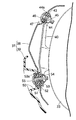
図3を併せて参照して、シリンダヘッド22の下部側面には、前記クランクケース20の右側下部から後輪WRの右側方に延出される排気管32の上流端が接続され、この排気管32の下流端には、前記スイングアーム34を前記後輪WRとの間に挟む位置に配置される排気マフラー33が接続される。而して排気マフラー33の下部の前後に間隔をあけた2箇所ならびに排気マフラー33の上部がボルト35…で前記スイングアーム34に締結される。
Referring also to FIG. 3, an upstream end of an
図4を併せて参照して、前記排気マフラー33の上部および外側面はプロテクタ37で覆われており、該プロテクタ37は、金属製の第1プロテクタ部材38と、合成樹脂製の第2プロテクタ部材39とで構成される。
Referring also to FIG. 4, the upper and outer surfaces of the
第1プロテクタ部材38は、排気マフラー33の少なくとも外側面を覆うように形成されるものであり、この実施例では、排気マフラー33の外側面を覆うようにしてたとえばステンレス鋼により形成される。また第2プロテクタ部材39は、第1プロテクタ部材38の上部を外部に露出させて第1プロテクタ部材38を外側方から覆うように形成されるものであり、この実施例では、第1プロテクタ部材38の下部を覆うようにして、たとえば耐熱性に優れたポリアミド樹脂等の合成樹脂により形成される。しかもこの第2プロテクタ部材39の上縁は、図3に示されるように該上縁の前後両端部よりも中間部が下がった湾曲形状に形成される。また図4に示されるように、第2プロテクタ部材39の上縁及び下縁と、第1プロテクタ部材38の表面との各間には隙間が形成される。
The
前記排気マフラー33の外側面の前部には、上下に長く延びる第1ブラケット40が溶接等で固着され、前記排気マフラー33の外側面の後部には、図3で示すように、第2および第3ブラケット41,42が上下に間隔をあけて溶接等で固着される。
A
第1ブラケット40の上部に対応した位置で第1プロテクタ部材38には内方に凹んだ凹部47が設けられており、該凹部47の中央部に、前記第1ブラケット40の上部に一端を当接せしめる弾性部材であるマウントゴム43が装着される。このマウントゴム43には、該マウントゴム43の他端に当接する鍔部44aを有するカラー44が挿通され、カラー44および第1ブラケット40に挿通されるボルト46が、第1ブラケット40の上部内面側に固着されるウエルドナット45に螺合される。すなわち第1ブラケット40の上部には、第1プロテクタ部材38の後部がマウントゴム43を有する弾性支持構造を介して支持される。
The
図3に注目して、第2ブラケット41に対応する部分で第1プロテクタ部材38の後部には内方に凹んだ凹部48が設けられており、該凹部48の中央部に配置されるボルト49により第1プロテクタ部材38の後部が第2ブラケット41に締結される。しかも第1プロテクタ部材38の後部および第2ブラケット41との間には、前記第1ブラケット40の上部への第1プロテクタ部材38の前部の弾性支持構造と同様の弾性支持構造が設けられる。すなわち第1プロテクタ部材38の上部の前部および後部は、排気マフラー33に固着された第1ブラケット40の上部および第2ブラケット41に弾性支持される。
Referring to FIG. 3, a recessed
再び図4において、第1ブラケット40の下部に対応する部分で第2プロテクタ部材39の前部には内方に凹んだ凹部50が設けられており、この凹部50の中央部には、第1プロテクタ部材38の外面に当接するカラー51が装着される。しかもカラー51を介して相互に当接する第1および第2プロテクタ部材38,39には、一端を第1ブラケット40の下部に当接させるマウントゴム52が装着される。このマウントゴム52には、該マウントゴム52の他端に当接する鍔部53aを有するカラー53が挿通され、カラー53および第1ブラケット40に挿通されるボルト55が、第1ブラケット40の下部内面側に固着されるウエルドナット54に螺合される。すなわち第1プロテクタ部材38の前部において第2プロテクタ部材39で覆われる部分ならびに第2プロテクタ部材39の前部は、共通なボルト55を用いた共締めによって第1ブラケット40の下部に弾性支持されることになる。
In FIG. 4 again, a
図3に注目して、第3ブラケット42に対応する部分で第2プロテクタ部材39の後部には内方に凹んだ凹部56が設けられており、該凹部56の中央部に配置されるボルト57を用いた共締めによって第1および第2プロテクタ部材38,39の後部が第3ブラケット42に締結される。しかも第1および第2プロテクタ部材38,39の後部および第3ブラケット42との間には、前記第1ブラケット40の下部への第1および第2プロテクタ部材38,39の前部の弾性支持構造と同様の弾性支持構造が設けられる。すなわち第2プロテクタ部材39は、第1プロテクタ部材38との共締めによって排気マフラー33に弾性支持される。
Paying attention to FIG. 3, a recessed
図5において、第1プロテクタ部材38には、その前部から前方に突出する支持板部38aが一体に設けられ、第2プロテクタ部材39の内面には、その支持板部38aに外側方から対向する取付け板部39aが一体に設けられる。しかも取付け板部39aには、ナット58が装着されており、支持板部38aおよび取付け板部39aに挿通されるねじ部材59がナット58に螺合される。
In FIG. 5, the
図6を併せて参照して、前記凹部50よりも前方で前記第2プロテクタ部材39の前部には、前方に臨む段部62aを後端に形成する凹部62が前方に向かうにつれて浅くなるようにして形成されており、前記段部62aには、排気マフラー33の外側面もしくは第1プロテクタ部材38に向けて走行風を導く走行風導入口61が、前記ボルト55を用いた第1および第2プロテクタ部材38,39への前記排気マフラー33への共締め箇所よりも前方に位置するようにして設けられる。また前記走行風導入口61は、図3に示されるように、該導入口61の開口部軸線を前下がりに傾斜させるようにして配置される。
Referring also to FIG. 6, the front part of the
図7および図8を併せて参照して、排気マフラー33には、その後端の中央部から後方に突出するテールパイプ64が設けられ、テールパイプ64の後端を臨ませる開口部66を有して前記排気マフラー33の後端およびテールパイプ64を覆うテールパイプカバー65が排気マフラー33に取付けられ、該テールパイプカバー65は、たとえば耐熱性に優れたポリアミド樹脂等の合成樹脂により形成される。
Referring to FIGS. 7 and 8 together, the
排気マフラー33の後端には第4ブラケット67が溶接等により固着されており、前記テールパイプ64の上方かつ第4ブラケット67の上部に対応した位置でテールパイプカバー64には内方に凹んだ凹部68が設けられる。該凹部68の中央部には第4ブラケット67の上部に一端を当接せしめるマウントゴム71が装着される。このマウントゴム71には、該マウントゴム71の他端に当接する鍔部72aを有するカラー72が挿通され、カラー72および第4ブラケット67に挿通されるボルト73が、第4ブラケット67の上部内面側に固着されるウエルドナット74に螺合される。すなわち第4ブラケット67の上部には、テールパイプカバー64の上部がマウントゴム71を有する弾性支持構造を介して支持される。
A
前記テールパイプ64の下方かつ第4ブラケット67の下部に対応した位置でテールパイプカバー64には内方に凹んだ凹部69が設けられる。該凹部69の中央部には第4ブラケット67の下部に一端を当接せしめるマウントゴム75が装着される。このマウントゴム75には、該マウントゴム75の他端に当接する鍔部76aを有するカラー76が挿通され、カラー76および第4ブラケット67に挿通されるボルト77が、第4ブラケット67の下部内面側に固着されるウエルドナット78に螺合される。すなわち第4ブラケット67の下部には、テールパイプカバー64の下部がマウントゴム75を有する弾性支持構造を介して支持される。
The
さらに自動二輪車の進行方向前方を向いた状態で前記テールパイプ64の右側方に位置する部分でテールパイプカバー65には内方に凹んだ凹部70が設けられ、該凹部70の中央部に配置されるボルト79により、テールパイプカバー65が第4ブラケット67に締結される。しかも前記テールパイプ64の右側方部分でのテールパイプカバー65および第4ブラケット67との間には、前記テールパイプカバー65の上部および下部の第4ブラケット67への弾性支持構造と同様の弾性支持構造が設けられる。すなわちテールパイプカバー65は、排気マフラー33の後端に固着された第4ブラケット67に弾性支持される。
Further, the
図9を併せて参照して、プロテクタ37における第2プロテクタ部材39の後部内面には、上下に延びる取付け板部39bが一体に設けられ、テールパイプカバー65には、前記取付け板部39bに後方側から対向する支持板部65aが一体に設けられる。而して支持板部65aの上部および下部には、ナット80…が装着され、取付け板部39bの上部および下部ならびに支持板部65aの上部および下部にそれぞれ挿通されるねじ部材81…が前記ナット80…に螺合される。これにより第2プロテクタ部材39の下部は、テールパイプカバー65を介して排気マフラー33の後端に弾性支持されることになる。
Referring also to FIG. 9, a mounting
ところで、図1で示すように、前記クランクケース20の右側下部から後輪WRの右側方に延出される排気管32の一部は車体カバー25から露出して配置されるものであり、この記排気管32のうち車体カバー25から露出する部分が、合成樹脂から成る排気管プロテクタ83で覆われる。この排気管プロテクタ83は、図10および図11で示すように、エンジン本体19におけるクランクケース20に、たとえば前後に間隔をあけた2箇所でボルト84,84によって締結される。
By the way, as shown in FIG. 1, a part of the
次にこの実施例の作用について説明すると、排気マフラー33の外側面を覆うロテクタ37は、排気マフラー33の少なくとも外側面を覆う金属製の第1プロテクタ部材38と、第1プロテクタ部材38の上部を外部に露出させて第1プロテクタ部材38を外側方から覆う合成樹脂製の第2プロテクタ部材39とから成るものである。したがって金属製の第1プロテクタ部材38の上部を外部に露出させることによって良好な放熱性を確保しつつ、合成樹脂から成る第2プロテクタ部材39で第1プロテクタ部材38を外側方から覆うことによって優れた断熱性を得ることができ、金属および合成樹脂が持つ利点を活かして排気マフラー33からの熱を優れた断熱性で遮断することができる。しかも第1プロテクタ部材38の耐久性を高めるとともに、金属光沢を有する第1プロテクタ部材38の上部を露出させることで、プロテクタ37の外観が高級感を有するようにして外観性を高めることができる。またプロテクタ37のうち外部から視認し得る部分の下部を、合成樹脂製であることから非光沢性である第2プロテクタ部材39で構成することにより、プロテクタ37の下部を目立たなくすることができ、それにより排気マフラー33が大きく見えないようにすることも可能である。
Next, the operation of this embodiment will be described. A
また第1および第2プロテクタ部材38,39が、ボルト55,57による共締めで排気マフラー33に支持されているので、第1および第2プロテクタ部材38,39を排気マフラー33に支持するための締結部品の個数を少なくし、部品点数を低減することができる。
In addition, since the first and
しかも第1および第2プロテクタ部材38,39が、マウントゴム43,52を介して排気マフラー33に支持されるものであるので、排気マフラー33からプロテクタ37側に伝わる振動を低減し、振動による騒音の発生を抑えることができるだけでなく、排気マフラー33からプロテクタ37側への熱伝導による伝熱量を小さく抑えることができる。
In addition, since the first and
また第2プロテクタ部材39に、排気マフラー33の外側面もしくは第1プロテクタ部材38に向けて走行風を導くようにした走行風導入口61が設けられるので、走行風をプロテクタ37内に導入し、金属製である排気マフラー33もしくは第1プロテクタ部材38を効果的に冷却し、冷却効率の向上を図ることができる。
Further, the
また排気マフラー33に、該排気マフラー33の後端から後方に突出するテールパイプ64が設けられるとともに、排気マフラー33の後端およびテールパイプ64を覆う合成樹脂製のテールパイプカバー65が取付けられるので、テールパイプ64および排気マフラー33の後端からの熱をテールパイプカバー65で遮断することができる。
Further, the
さらに排気管32のうち車体カバー25から露出する部分が、排気管プロテクタ83で覆われるので、排気管32からの熱が外部に放射されるのを遮断することができる。
Further, the portion of the
以上、本発明の実施例を説明したが、本発明は上記実施例に限定されるものではなく、特許請求の範囲に記載された本発明を逸脱することなく種々の設計変更を行うことが可能である。 Although the embodiments of the present invention have been described above, the present invention is not limited to the above-described embodiments, and various design changes can be made without departing from the present invention described in the claims. It is.
19・・・エンジン本体
22・・・シリンダヘッド
32・・・排気管
33・・・排気マフラー
37・・・プロテクタ
38・・・第1プロテクタ部材
39・・・第2プロテクタ部材
43,52・・・弾性部材であるマウントゴム
51・・・カラー
61・・・走行風導入口
64・・・テールパイプ
65・・・テールパイプカバー
83・・・排気管プロテクタ
DESCRIPTION OF
Claims (8)
前記プロテクタ(37)が、前記排気マフラー(33)の少なくとも外側面を覆う金属製の第1プロテクタ部材(38)と、第1プロテクタ部材(38)の上部を外部に露出させて第1プロテクタ部材(38)の下部を外側方から覆う合成樹脂製の第2プロテクタ部材(39)とから成り、
前記第2プロテクタ部材(39)の上縁は、その上縁の前後両端部よりも中間部が下がった湾曲形状に形成され、
前記第2プロテクタ部材(39)には、前記第1プロテクタ部材(38)の上部の露出部に向けて走行風を導く走行風導入口(61)が、その導入口(61)の開口部軸線を前下がりに傾斜させるようにして設けられることを特徴とする自動二輪車の排気装置。 An exhaust muffler (33) is connected to an exhaust pipe (32) extending from a cylinder head (22) of an engine body (19), and an outer surface of the exhaust muffler (33) is covered with a protector (37). In the exhaust system,
The protector (37) exposes the metal first protector member (38) covering at least the outer surface of the exhaust muffler (33) and the first protector member (38) to the outside, and the first protector member. (38) the second protector member (39) under the synthetic resin covering the outer side of the formed Ri from
The upper edge of the second protector member (39) is formed in a curved shape in which the middle part is lower than the front and rear end parts of the upper edge,
The second protector member (39) has a traveling wind inlet (61) for guiding the traveling wind toward the exposed portion at the top of the first protector member (38), and the opening axis of the inlet (61). An exhaust device for a motorcycle, wherein the exhaust device is provided so as to be inclined forward and downward .
Priority Applications (3)
| Application Number | Priority Date | Filing Date | Title |
|---|---|---|---|
| JP2006274720A JP4700586B2 (en) | 2006-10-06 | 2006-10-06 | Motorcycle exhaust system |
| EP20070018317 EP1911945B1 (en) | 2006-10-06 | 2007-09-18 | Exhaust system for motorcycle |
| CN200710161807A CN100593075C (en) | 2006-10-06 | 2007-09-24 | Exhaust system for motorcycle |
Applications Claiming Priority (1)
| Application Number | Priority Date | Filing Date | Title |
|---|---|---|---|
| JP2006274720A JP4700586B2 (en) | 2006-10-06 | 2006-10-06 | Motorcycle exhaust system |
Publications (3)
| Publication Number | Publication Date |
|---|---|
| JP2008095509A JP2008095509A (en) | 2008-04-24 |
| JP2008095509A5 JP2008095509A5 (en) | 2009-11-05 |
| JP4700586B2 true JP4700586B2 (en) | 2011-06-15 |
Family
ID=38710508
Family Applications (1)
| Application Number | Title | Priority Date | Filing Date |
|---|---|---|---|
| JP2006274720A Expired - Fee Related JP4700586B2 (en) | 2006-10-06 | 2006-10-06 | Motorcycle exhaust system |
Country Status (3)
| Country | Link |
|---|---|
| EP (1) | EP1911945B1 (en) |
| JP (1) | JP4700586B2 (en) |
| CN (1) | CN100593075C (en) |
Cited By (1)
| Publication number | Priority date | Publication date | Assignee | Title |
|---|---|---|---|---|
| EP2664761A1 (en) | 2012-05-18 | 2013-11-20 | Honda Motor Co., Ltd. | Muffler unit for saddle-ride type vehicle |
Families Citing this family (18)
| Publication number | Priority date | Publication date | Assignee | Title |
|---|---|---|---|---|
| JP2009264293A (en) * | 2008-04-25 | 2009-11-12 | Yamaha Motor Co Ltd | Vehicle and muffler protector unit |
| JP5315072B2 (en) | 2009-01-30 | 2013-10-16 | 本田技研工業株式会社 | Muffler cover for saddle-ride type vehicles |
| JP2012254750A (en) * | 2011-06-10 | 2012-12-27 | Yamaha Motor Co Ltd | Muffler protector and saddle-ride type vehicle |
| JP5867852B2 (en) * | 2011-09-21 | 2016-02-24 | 本田技研工業株式会社 | Muffler device with protector for small vehicles |
| KR101284328B1 (en) * | 2011-12-08 | 2013-07-08 | 현대자동차주식회사 | Muffler for vehicle |
| JP5911336B2 (en) * | 2012-02-27 | 2016-04-27 | 本田技研工業株式会社 | Small vehicle |
| CN102733920A (en) * | 2012-06-28 | 2012-10-17 | 力帆实业(集团)股份有限公司 | Silencer assembly of motorcycle |
| JP5847051B2 (en) * | 2012-09-28 | 2016-01-20 | 本田技研工業株式会社 | Exhaust device for saddle riding type vehicle |
| JP6446206B2 (en) * | 2014-09-01 | 2018-12-26 | 川崎重工業株式会社 | Vehicle cover structure |
| JP6236700B2 (en) * | 2014-09-30 | 2017-11-29 | 本田技研工業株式会社 | Silencer structure for saddle-ride type vehicles |
| TWI593871B (en) * | 2015-11-24 | 2017-08-01 | Kwang Yang Motor Co | Engine exhaust pipe cover fixed structure |
| CN105508024A (en) * | 2015-11-30 | 2016-04-20 | 宁波大叶园林设备有限公司 | Double-layered cooling and noise-elimination two-stroke LPG engine with lengthened and enlarged wrapping resin |
| DE102016113231A1 (en) | 2016-07-19 | 2018-01-25 | Eberspächer Exhaust Technology GmbH & Co. KG | Nozzle assembly, in particular for an exhaust treatment arrangement of an exhaust system of an internal combustion engine |
| JP6752973B2 (en) * | 2017-07-28 | 2020-09-09 | 本田技研工業株式会社 | Muffler cover structure for saddle-riding vehicles |
| CN110017204B (en) * | 2017-11-15 | 2021-11-19 | 本田技研工业株式会社 | Mounting structure of end cover |
| JP6648197B2 (en) * | 2018-06-26 | 2020-02-14 | 本田技研工業株式会社 | Exhaust system for motorcycle |
| JP7215330B2 (en) | 2019-05-28 | 2023-01-31 | スズキ株式会社 | Exhaust system and straddle-type vehicle |
| JP7245349B2 (en) * | 2019-09-26 | 2023-03-23 | 本田技研工業株式会社 | Straddle-type vehicle exhaust system |
Citations (5)
| Publication number | Priority date | Publication date | Assignee | Title |
|---|---|---|---|---|
| JPH0953444A (en) * | 1995-08-10 | 1997-02-25 | Suzuki Motor Corp | Engine working machinery |
| JPH10121957A (en) * | 1996-10-14 | 1998-05-12 | Suzuki Motor Corp | Heat insulation cover for vehicle exhaust device |
| JPH11182228A (en) * | 1997-12-16 | 1999-07-06 | Kawasaki Heavy Ind Ltd | Exhaust muffler for motorcycle and manufacture thereof |
| JP2005083286A (en) * | 2003-09-09 | 2005-03-31 | Honda Motor Co Ltd | Exhaust apparatus |
| JP2005344552A (en) * | 2004-06-01 | 2005-12-15 | Honda Motor Co Ltd | Muffler device for motorcycle |
Family Cites Families (3)
| Publication number | Priority date | Publication date | Assignee | Title |
|---|---|---|---|---|
| JP3010874B2 (en) | 1992-01-31 | 2000-02-21 | スズキ株式会社 | Auxiliary equipment support structure for motorcycles |
| JP2001073758A (en) | 1999-08-31 | 2001-03-21 | Yamaha Motor Co Ltd | Muffler of two-wheeled vehicle |
| JP2006044633A (en) * | 2004-03-19 | 2006-02-16 | Yamaha Motor Co Ltd | Riding type vehicle |
-
2006
- 2006-10-06 JP JP2006274720A patent/JP4700586B2/en not_active Expired - Fee Related
-
2007
- 2007-09-18 EP EP20070018317 patent/EP1911945B1/en active Active
- 2007-09-24 CN CN200710161807A patent/CN100593075C/en not_active Expired - Fee Related
Patent Citations (5)
| Publication number | Priority date | Publication date | Assignee | Title |
|---|---|---|---|---|
| JPH0953444A (en) * | 1995-08-10 | 1997-02-25 | Suzuki Motor Corp | Engine working machinery |
| JPH10121957A (en) * | 1996-10-14 | 1998-05-12 | Suzuki Motor Corp | Heat insulation cover for vehicle exhaust device |
| JPH11182228A (en) * | 1997-12-16 | 1999-07-06 | Kawasaki Heavy Ind Ltd | Exhaust muffler for motorcycle and manufacture thereof |
| JP2005083286A (en) * | 2003-09-09 | 2005-03-31 | Honda Motor Co Ltd | Exhaust apparatus |
| JP2005344552A (en) * | 2004-06-01 | 2005-12-15 | Honda Motor Co Ltd | Muffler device for motorcycle |
Cited By (2)
| Publication number | Priority date | Publication date | Assignee | Title |
|---|---|---|---|---|
| EP2664761A1 (en) | 2012-05-18 | 2013-11-20 | Honda Motor Co., Ltd. | Muffler unit for saddle-ride type vehicle |
| JP2013241856A (en) * | 2012-05-18 | 2013-12-05 | Honda Motor Co Ltd | Muffler unit for saddle-ride type vehicle |
Also Published As
| Publication number | Publication date |
|---|---|
| EP1911945B1 (en) | 2011-02-02 |
| CN100593075C (en) | 2010-03-03 |
| JP2008095509A (en) | 2008-04-24 |
| EP1911945A1 (en) | 2008-04-16 |
| CN101158304A (en) | 2008-04-09 |
Similar Documents
| Publication | Publication Date | Title |
|---|---|---|
| JP4700586B2 (en) | Motorcycle exhaust system | |
| JP2008095509A5 (en) | ||
| JP5033585B2 (en) | Motorcycle seat rail | |
| EP2028095A2 (en) | Motorcycle | |
| JP2007076423A (en) | Cowling of motorcycle | |
| US20050067211A1 (en) | Exhaust control apparatus for a vehicle, and vehicle including same | |
| JP2007085235A (en) | Exhaust muffler of motorcycle | |
| JP5820443B2 (en) | Scooter type vehicle | |
| JP5525333B2 (en) | Arrangement structure of canister in vehicle | |
| JP2013010422A (en) | Saddle type vehicle | |
| JP5837777B2 (en) | Saddle riding vehicle | |
| JP2003320979A (en) | Rear lighting system for motorcycle | |
| JP5847775B2 (en) | Fuel tank mounting structure for saddle-ride type vehicles | |
| JP2006123656A (en) | Saddle riding type vehicle | |
| JP4847925B2 (en) | Horn mounting structure | |
| JP4391931B2 (en) | Motorcycle seat support structure | |
| JP5570940B2 (en) | Saddle riding | |
| JPH02197484A (en) | Side cover heat shielding device for motorcycle | |
| JP4890274B2 (en) | Front and fender structure of motorcycle and tricycle | |
| JP6216271B2 (en) | Exhaust pipe with catalyst for saddle-ride type vehicles | |
| JP2011247217A (en) | Exhaust gas passage structure of internal combustion engine | |
| JP3941803B2 (en) | Scooter-type vehicle intake system | |
| JP2016068777A (en) | Saddle-riding type vehicle | |
| JP2015092070A (en) | Saddle-riding type vehicle | |
| JP2005225383A (en) | Lower structure of motorcycle body |
Legal Events
| Date | Code | Title | Description |
|---|---|---|---|
| A521 | Written amendment |
Free format text: JAPANESE INTERMEDIATE CODE: A523 Effective date: 20090917 |
|
| A621 | Written request for application examination |
Free format text: JAPANESE INTERMEDIATE CODE: A621 Effective date: 20090917 |
|
| A977 | Report on retrieval |
Free format text: JAPANESE INTERMEDIATE CODE: A971007 Effective date: 20101117 |
|
| A131 | Notification of reasons for refusal |
Free format text: JAPANESE INTERMEDIATE CODE: A131 Effective date: 20101201 |
|
| A521 | Written amendment |
Free format text: JAPANESE INTERMEDIATE CODE: A523 Effective date: 20110127 |
|
| TRDD | Decision of grant or rejection written | ||
| A01 | Written decision to grant a patent or to grant a registration (utility model) |
Free format text: JAPANESE INTERMEDIATE CODE: A01 Effective date: 20110223 |
|
| A61 | First payment of annual fees (during grant procedure) |
Free format text: JAPANESE INTERMEDIATE CODE: A61 Effective date: 20110304 |
|
| R150 | Certificate of patent or registration of utility model |
Ref document number: 4700586 Country of ref document: JP Free format text: JAPANESE INTERMEDIATE CODE: R150 |
|
| LAPS | Cancellation because of no payment of annual fees |