EP1911945B1 - Exhaust system for motorcycle - Google Patents
Exhaust system for motorcycle Download PDFInfo
- Publication number
- EP1911945B1 EP1911945B1 EP20070018317 EP07018317A EP1911945B1 EP 1911945 B1 EP1911945 B1 EP 1911945B1 EP 20070018317 EP20070018317 EP 20070018317 EP 07018317 A EP07018317 A EP 07018317A EP 1911945 B1 EP1911945 B1 EP 1911945B1
- Authority
- EP
- European Patent Office
- Prior art keywords
- protector
- exhaust
- exhaust muffler
- pipe
- protector member
- Prior art date
- Legal status (The legal status is an assumption and is not a legal conclusion. Google has not performed a legal analysis and makes no representation as to the accuracy of the status listed.)
- Active
Links
Images


Classifications
-
- B—PERFORMING OPERATIONS; TRANSPORTING
- B62—LAND VEHICLES FOR TRAVELLING OTHERWISE THAN ON RAILS
- B62J—CYCLE SADDLES OR SEATS; AUXILIARY DEVICES OR ACCESSORIES SPECIALLY ADAPTED TO CYCLES AND NOT OTHERWISE PROVIDED FOR, e.g. ARTICLE CARRIERS OR CYCLE PROTECTORS
- B62J23/00—Other protectors specially adapted for cycles
-
- F—MECHANICAL ENGINEERING; LIGHTING; HEATING; WEAPONS; BLASTING
- F01—MACHINES OR ENGINES IN GENERAL; ENGINE PLANTS IN GENERAL; STEAM ENGINES
- F01N—GAS-FLOW SILENCERS OR EXHAUST APPARATUS FOR MACHINES OR ENGINES IN GENERAL; GAS-FLOW SILENCERS OR EXHAUST APPARATUS FOR INTERNAL COMBUSTION ENGINES
- F01N1/00—Silencing apparatus characterised by method of silencing
-
- F—MECHANICAL ENGINEERING; LIGHTING; HEATING; WEAPONS; BLASTING
- F01—MACHINES OR ENGINES IN GENERAL; ENGINE PLANTS IN GENERAL; STEAM ENGINES
- F01N—GAS-FLOW SILENCERS OR EXHAUST APPARATUS FOR MACHINES OR ENGINES IN GENERAL; GAS-FLOW SILENCERS OR EXHAUST APPARATUS FOR INTERNAL COMBUSTION ENGINES
- F01N13/00—Exhaust or silencing apparatus characterised by constructional features ; Exhaust or silencing apparatus, or parts thereof, having pertinent characteristics not provided for in, or of interest apart from, groups F01N1/00 - F01N5/00, F01N9/00, F01N11/00
- F01N13/14—Exhaust or silencing apparatus characterised by constructional features ; Exhaust or silencing apparatus, or parts thereof, having pertinent characteristics not provided for in, or of interest apart from, groups F01N1/00 - F01N5/00, F01N9/00, F01N11/00 having thermal insulation
-
- F—MECHANICAL ENGINEERING; LIGHTING; HEATING; WEAPONS; BLASTING
- F01—MACHINES OR ENGINES IN GENERAL; ENGINE PLANTS IN GENERAL; STEAM ENGINES
- F01N—GAS-FLOW SILENCERS OR EXHAUST APPARATUS FOR MACHINES OR ENGINES IN GENERAL; GAS-FLOW SILENCERS OR EXHAUST APPARATUS FOR INTERNAL COMBUSTION ENGINES
- F01N13/00—Exhaust or silencing apparatus characterised by constructional features ; Exhaust or silencing apparatus, or parts thereof, having pertinent characteristics not provided for in, or of interest apart from, groups F01N1/00 - F01N5/00, F01N9/00, F01N11/00
- F01N13/18—Construction facilitating manufacture, assembly, or disassembly
- F01N13/1805—Fixing exhaust manifolds, exhaust pipes or pipe sections to each other, to engine or to vehicle body
- F01N13/1811—Fixing exhaust manifolds, exhaust pipes or pipe sections to each other, to engine or to vehicle body with means permitting relative movement, e.g. compensation of thermal expansion or vibration
-
- B—PERFORMING OPERATIONS; TRANSPORTING
- B62—LAND VEHICLES FOR TRAVELLING OTHERWISE THAN ON RAILS
- B62K—CYCLES; CYCLE FRAMES; CYCLE STEERING DEVICES; RIDER-OPERATED TERMINAL CONTROLS SPECIALLY ADAPTED FOR CYCLES; CYCLE AXLE SUSPENSIONS; CYCLE SIDE-CARS, FORECARS, OR THE LIKE
- B62K2202/00—Motorised scooters
-
- F—MECHANICAL ENGINEERING; LIGHTING; HEATING; WEAPONS; BLASTING
- F01—MACHINES OR ENGINES IN GENERAL; ENGINE PLANTS IN GENERAL; STEAM ENGINES
- F01N—GAS-FLOW SILENCERS OR EXHAUST APPARATUS FOR MACHINES OR ENGINES IN GENERAL; GAS-FLOW SILENCERS OR EXHAUST APPARATUS FOR INTERNAL COMBUSTION ENGINES
- F01N2260/00—Exhaust treating devices having provisions not otherwise provided for
- F01N2260/20—Exhaust treating devices having provisions not otherwise provided for for heat or sound protection, e.g. using a shield or specially shaped outer surface of exhaust device
-
- F—MECHANICAL ENGINEERING; LIGHTING; HEATING; WEAPONS; BLASTING
- F01—MACHINES OR ENGINES IN GENERAL; ENGINE PLANTS IN GENERAL; STEAM ENGINES
- F01N—GAS-FLOW SILENCERS OR EXHAUST APPARATUS FOR MACHINES OR ENGINES IN GENERAL; GAS-FLOW SILENCERS OR EXHAUST APPARATUS FOR INTERNAL COMBUSTION ENGINES
- F01N2450/00—Methods or apparatus for fitting, inserting or repairing different elements
- F01N2450/24—Methods or apparatus for fitting, inserting or repairing different elements by bolts, screws, rivets or the like
Definitions
- the present invention relates to an exhaust system for a motorcycle according to the preamble of claim 1, in which an exhaust muffler is connected to an exhaust pipe extending from a cylinder head of an engine body, and in which a protector covers the upper portion of the exhaust muffler and the outer side surface of the exhaust muffler.
- An exhaust system according to the preamble of claim 1 is known from JP 10-121957 A .
- JP 2001-073758 A discloses a further exhaust system for a motorcycle, in which an outer side surface of an exhaust muffler is covered with a single protector made of synthetic resin.
- Japanese Unexamined Patent Application Publication No. JP 05-209519 A discloses a structure in which a single metal protector covers the upper portion of an exhaust muffler.
- Japanese Patent Application Laid-Open Publication No. JP 2005-344552 A discloses another structure, in which synthetic-resin double protector members--an inner and an outer protector memberscover the outer side surface of the exhaust muffler.
- An advantage of the disclosure of Japanese Unexamined Patent Application Publication No. JP 05-209519 A is that the metal protector is easy to be cooled by the traveling wind. Within the metal protector that has a high thermal conductivity, the portion that covers the upper portion of the exhaust muffler becomes at a higher temperature than any other portion of the protector, and the heat transferred to the protector at the above-mentioned portion tends to spread to the entire portion of the protector. In addition, a metallic surface extending all over the side surface of the exhaust muffler shows a strong presence of the muffler, but makes the muffler look heavy. A heavy-looking appearance is unlikely to match the sporty image of motorcycles. An advantage of the disclosure of Japanese Patent Application Laid-Open Publication No.
- JP 2005-344552 A is that the synthetic-resin double--inner and outer--protector members constitute the protector and can reduce the spread of the heat.
- the protector tends to accumulate heat and is difficult to be cooled by the traveling wind.
- the synthetic-resin protector needs to enhance the durability, which is not a pressing problem in the case of metal protectors.
- a glossy finish when desired, needs a coating process or the like, and this makes the protector expensive.
- the present invention provides an exhaust system for a motorcycle with the following characteristics.
- an exhaust muffler is connected to an exhaust pipe extending from a cylinder head of an engine body, and the outer side surface of the exhaust muffler is covered with a protector.
- the protector includes a first protector member, which is made of a metal, and which covers the outer side surface of the exhaust muffler.
- the protector also includes a second protector member, which is made of a synthetic resin, and which covers the first protector member from the outer side while an upper portion of the first protector member is left uncovered so as to be exposed to the outside.
- first and the second protector members are fastened together to, and supported by, the exhaust muffler.
- a traveling-wind introduction port is formed in the second protector member so as to guide the traveling wind towards any one of the outer surface of the exhaust muffler and the first protector member.
- the first and the second protector members are supported by the exhaust muffler with respective elastic members interposed in between.
- a tail pipe is formed in the exhaust muffler so as to protrude rearward from the rear end of the exhaust muffler
- a tail-pipe cover which is made of a synthetic resin, and which covers the rear end of the exhaust muffler and the tail pipe, is attached to the exhaust muffler.
- a part exposed from a body cover is covered with an exhaust-pipe protector.
- rubber mounts 43, 52 correspond to the elastic member of the present invention.
- the present invention by exposing the upper portion of the metallic first protector member to the outside, favorable heat radiation is accomplished.
- the second protector member made of a synthetic resin, covers the first protector member from the outer side, and thus an excellent heat insulating property is obtained. Taking advantage of metals and synthetic resins, the heat from the exhaust muffler is blocked as the protector has an excellent heat insulating property. In addition, a higher durability of the first protector member is accomplished.
- the exposed upper portion of the first protector member with metallic luster gives a classy impression to the protector, and improves the external appearance of the protector.
- the lower portion of a part that is visible from the outside is composed of the second protector member, which is made of a synthetic resin and which is thus not glossy. Consequently, the lower portion of the protector has a low profile, so that the exhaust muffler is made to look not as big as it really is.
- the traveling wind introduced into the protector is used to effectively cool down the metallic exhaust muffler or the metallic first protector member.
- an improved cooling efficiency is accomplished.
- the vibration to be transmitted from the exhaust muffler to the protector side is reduced, and generation of the noise due to the vibration is also reduced.
- the amount of heat transferred, by heat conduction, from the exhaust muffler to the protector side is also made smaller.
- the heat from the tail pipe and the rear end portion of the exhaust muffler is blocked by the tail-pipe cover.
- the portion exposed from the body cover is covered with the exhaust pipe protector. As a result, heat from the exhaust pipe is blocked from radiating to the outside.
- FIG. 1 and Fig. 2 show a low-floor scooter-type motorcycle with a floor 11.
- a body frame F that the motorcycle has includes a head pipe 13, which rotatably supports a steerable front fork 12, which, in turn, pivotally supports a front wheel WF.
- the body frame F also includes a right and left pair of side frames 14..., each of which has a front end portion joined to the head pipe 13.
- Each side frame 14 is formed by bending a single pipe, and thus includes, as a unit, a down frame portion 14a, a lower frame portion 14b, a rising frame portion 14c, and a seat rail portion 14d.
- the down frame portion 14a droops down from the head pipe 13.
- the lower frame portion 14b is formed as extending from the bottom end of the down frame portion 14a and then rearwards under the floor 11.
- the rear half of the lower frame portion 14b is formed so as to be inclined upward to the rear.
- the rising frame portion 14c extends from the rear end of the lower frame portion 14b, and rises upward at a position behind the floor 11.
- the seat rail portion 14d extends rearward from the rear end of the rising frame portion 14c so as to support a riding seat 15.
- a rear sub-frame 16 is provided between a rear portion of the lower frame portion 14b and a front portion of the seat rail portion 14d.
- Each rear sub-frame 16 is positioned below the seat rail portion 14d and at the rear of the rising frame portion 14c.
- Each of pivot plates 17... is provided between each of the two side frames 14... and the corresponding one of the rear sub-frames 16.
- the pivot plates 17... provided to the body frame F support the power unit P with a link mechanism 18 so as to swing up and down.
- the power unit P includes an engine E, which is placed in front of a rear wheel WR, and also includes a transmission system M, which is placed on the left side of the rear wheel WR.
- the rear wheel WR is pivotally supported by a rear portion of the power unit P.
- the transmission system M includes a V-belt continuously variable transmission (not illustrated) and a reduction gear train (not illustrated), which transmits the power outputted from the continuously variable transmission to the axle of the rear wheel WR while reduces the speed of the outputted.
- the engine E is a single-cylinder water-cooling four-cycle engine.
- a crankcase 20 (see Fig. 3 ) forms a part of an engine body 19 of the engine E includes.
- a transmission case 23 is provided contiguously to the crankcase 20, and extends to the left side of the rear wheel WR.
- the transmission system M is housed in the transmission case 23.
- a swing arm 34 is fixed to the crankcase 20, and extends to the right side of the rear wheel WR.
- the swing arm 34 pivotally supports the rear wheel WR together with the transmission case 23 of the power unit P.
- Each of Rear cushion units 24, 24 is provided between rear portion of the respective seat rail portions 14d... and each one of a rear portion of the transmission case 23 and a rear portion of the swing arm 34.
- a body cover 25 of a synthetic resin is provided to cover a part of the engine body 19 and the body frame F, and the floor 11 is formed in the body cover 25.
- the body of a scooter-type vehicle with a sporty, light-weighted image is formed by the simple body frame F and the body cover 25 to cover a relatively small area.
- An air cleaner 27 is placed above and supported by the transmission case 23.
- the upstream end of an inlet pipe 28 is connected to the air cleaner 27.
- a throttle body 29 is provided between the downstream end of the inlet pipe 28 and a cylinder head 22 of the engine body 19.
- a fuel injection valve 30 is attached to the cylinder head 22 to inject the fuel into the air passing through the throttle body 29.
- An exhaust pipe 32 extends from a right-side lower portion of the crankcase 20 to the right side of the rear wheel WR.
- the exhaust pipe 32 has an upstream end connected to the lower side surface of the cylinder head 22 while the downstream end of the exhaust pipe 32 is connected to an exhaust muffler 33.
- the exhaust muffler 33 is placed in a position such that the swing arm 34 is interposed between the exhaust muffler 33 and the rear wheel WR.
- the exhaust muffler 33 is fastened to the swing arm 34 with bolts 35... at a position in the upper portion of the exhaust muffler 33 and at two positions--one in front and the other in the rear with a certain interval--in the lower portion thereof.
- a protector 37 is provided to cover the upper portion of and the outer side surface of the exhaust muffler 33.
- the protector 37 is composed of a first protector member 38, which is made of a metal, and a second protector member 39, which is made of a synthetic resin.
- the first protector member 38 is formed to cover at least the outer side surface of the exhaust muffler 33.
- the first protector member 38 of this embodiment is formed to cover the outer side surface of the exhaust muffler 33, and is made of a stainless steel, for example.
- the second protector member 39 is formed to cover the first protector member 38 from the outside while the upper portion of the first protector member 38 is left uncovered so as to be exposed to the outside.
- the second protector member 39 of this embodiment is formed to cover the lower portion of the first protector member 38, and is made of a synthetic resin, such as a polyamide resin that is excellent in heat resistance.
- a first bracket 40 elongated in the vertical direction, is fixed, by welding or the like, to a front portion of the outer side surface of the exhaust muffler 33.
- a second and a third brackets 41 and 42 are fixed, by welding or the like, to a rear portion of the outer side surface of the exhaust muffler 33 respectively at two positions--one in the upper and the other in the lower positions--with a certain interval, as Fig. 3 shows.
- a recessed portion 47, sunk inward, is formed in the first protector member 38, and at a position corresponding to an upper portion of the first bracket 40.
- a rubber mount 43 is installed in the center of the recessed portion 47.
- the rubber mount 43 is an elastic member and has a first end that is brought into contact with the upper portion of the first bracket 40.
- a collar 44 is inserted into the rubber mount 43, and has a brim portion 44a, which is brought into contact with a second end of the rubber mount 43.
- a bolt 46 is inserted into the collar 44 and the first bracket 40, and is screwed into a weld nut 45, which is firmly attached to the inner surface side of the upper portion of the first bracket 40.
- a rear portion of the first protector member 38 is supported in an upper portion of the first bracket 40 via an elastic support structure with a rubber mount 43.
- a recessed portion 48 is formed in a rear portion of the first protector member 38, and at a portion corresponding to the second bracket 41.
- a bolt 49 is disposed at the center of the recessed portion 48, and fastens the rear portion of the first protector member 38 to the second bracket 41.
- an elastic support structure is provided between a rear portion of the first protector member 38 and the second bracket 41.
- the provided elastic support structure is similar to the structure provided to elastically support the front portion of the first protector member 38 at the upper portion of the first bracket 40.
- a front and a rear portions of the upper portion of the first protector member 38 are elastically supported by an upper portion of the first bracket 40 and by the second bracket 41, both of which brackets are firmly attached to the exhaust muffler 33.
- a recessed portion 50 is formed in a front portion of the second protector member 39, and at a position corresponding to a lower portion of the first bracket 40.
- a collar 51 is installed in the center of the recessed portion 50. The collar 51 is brought into contact with the outer surface of the first protector member38.
- a rubber mount 52 is installed between the first and the second protector members 38, 39, which are brought into contact with each other with the collar 51 interposed in between.
- a first end of the rubber mount 52 is brought into contact with a lower portion of the first bracket 40.
- Another collar 53 which has a brim portion 53a is inserted into the rubber mount 52.
- the brim portion 53a is brought into contact with a second end of the rubber mount 52.
- a bolt 55 is inserted into the collar 53 and the first bracket 40, and is screwed into a weld nut 54, which is firmly attached to the inner surface side of the lower portion of the first bracket 40.
- the bolt 55 is used commonly to fasten both the front portion of the second protector member 39 and the front portion of the first protector member 38, which front portion is covered with the second protector member 39.
- the two portions thus fastened together are elastically supported by the lower portion of the first bracket 40.
- a recessed portion 56 is formed in a rear portion of the second protector member 39, and at a portion corresponding to the third bracket 42.
- a bolt 57 is used commonly to fasten both the rear portions of the respective first and second protector members 38 and 39 to the third bracket 42.
- an elastic support structure is provided between the third bracket 42 and the rear portions of the respective first and second protector members 38 and 39.
- the provided elastic support structure is similar to the structure provided to elastically support the front portions of the respective first and second protector members 38 and 39 at the lower portion of the first bracket 40.
- the second protector member is supported by the exhaust muffler 33 by being fastened together with the first protector member 38 to the exhaust muffler 33.
- a support-plate portion 38a is formed integrally with the first protector member 38 so as to protrude forward from a front portion of the first protector member 38.
- An attachment-plate portion 39a is formed in the inner surface of the second protector member 39, and is formed integrally with the second protector member 39.
- the attachment-plate portion is opposed to the support-plate portion 38a from the outer side.
- a nut 58 is attached to the attachment-plate portion 39a, and a screw member 59, which is inserted into the respective support-plate portion 38a and attachment-plate portion 39a, is screwed into the nut 58.
- a recessed portion 62 is formed in a front portion of the second protector member 39 with its depth gradually becoming shallower to the front.
- a step portion 62, which faces forward, is formed at the rear end of the recessed portion 62.
- a traveling-wind introduction port 61 is formed in the step portion 62a, and guides the traveling wind towards the outer side surface of the exhaust muffler 33 or towards the first protector member 38.
- a tail pipe 64 is formed in the exhaust muffler 33 so as to protrude rearward from a center portion of the rear end of the exhaust muffler 33.
- a tail-pipe cover 65 is attached to the exhaust muffler 33.
- the tail-pipe cover 65 with an opening portion 66 facing the rear end of the tail pipe 64, covers the rear end of the exhaust muffler 33 and the tail pipe 64.
- the tail-pipe cover is made of a synthetic resin, such as a polyamide resin that is excellent in heat resistance.
- a fourth bracket 67 is firmly attached, by welding or the like, to the rear end of the muffler 33.
- a recessed portion 68, sunk inward, is formed in the tail-pipe cover 64, above the tail pipe 64, and at a position corresponding to an upper portion of the fourth bracket 67.
- a rubber mount 71 is installed in the center of the recessed portion 68. The rubber mount 71 has a first end that is brought into contact with the upper portion of the fourth bracket 67.
- a collar 72 is inserted into the rubber mount 71, and has a brim portion 72a, which is brought into contact with a second end of the rubber mount 71.
- a bolt 73 is inserted into the collar 72 and the fourth bracket 67, and is screwed into a weld nut 74, which is firmly attached to the inner surface side of the upper portion of the fourth bracket 67.
- the upper portion of the tail-pipe cover 64 is supported by the upper portion of the fourth bracket 67 via an elastic support structure with a rubber mount 71.
- a recessed portion 69, sunk inward, is formed in the tail-pipe cover 64, below the tail pipe 64, and at a position corresponding to a lower portion of the fourth bracket 67.
- a rubber mount 75 is installed in the center of the recessed portion 69. The rubber mount 75 has a first end that is brought into contact with the lower portion of the fourth bracket 67.
- a collar 76 is inserted into the rubber mount 75, and has a brim portion 76a, which is brought into contact with a second end of the rubber mount 75.
- a bolt 77 is inserted into the collar 76 and the fourth bracket 67, and is screwed into a weld nut 78, which is firmly attached to the inner surface side of the lower portion of the fourth bracket 67.
- the lower portion of the tail-pipe cover 64 is supported by the lower portion of the fourth bracket 67 via an elastic support structure with a rubber mount 75.
- a recessed portion 70 is formed in the tail-pipe cover 65, and at a portion positioned on the right side of the tail pipe 64 when viewed towards the front in the traveling direction of the motorcycle.
- a bolt is disposed at the center of the recessed portion 70, and fastens the tail-pipe cover 65 to the fourth bracket 67.
- an elastic support structure is provided between the fourth bracket 67 and a portion of the tail-pipe cover 65, which portion is located at the right side of the tail pipe 64.
- the provided elastic support structure is similar to the elastic support structures provided to each of the upper and the lower portions of the fourth bracket 67.
- the fourth bracket 67 which is firmly attached to the rear end of the exhaust muffler 33, elastically supports the tail-pipe cover 65.
- An attachment-plate portion 39b stretching vertically, is formed in the inner surface of a rear portion of the second protector member 39 within the protector 37, and is formed integrally with the second protector member 39.
- a support-plate portion 65a is formed integrally with the tail-pipe cover 65 so as to be opposed to the attachment-plate portion 39b from the rear side.
- nuts 80... are attached to each of the upper and the lower portions of the support-plate portion 65a.
- Screw members 81... which are inserted into respective upper and lower portions of each of the attachment-plate portion 39b and of the support-plate portion 65a and, are screwed into the corresponding nuts 58. In this way, the lower portion of the second protector member 39 is elastically supported by the rear end of the exhaust muffler 33 with the tail-pipe cover 65.
- a part of the exhaust pipe 32 extending to the right side of the rear wheel WR from the right-side lower portion of the crankcase 20 is disposed as being exposed from the body cover 25.
- an exhaust-pipe protector 83 made of a synthetic resin As Fig. 10 and Fig. 11 show, the exhaust-pipe protector 83 is fastened, by bolts 84,84, to the crankcase 20 of the engine body 19, for example at two positions--one in front and the other at the rear--with a certain interval in between.
- the protector 37 which covers the outer side surface of the exhaust muffler 33, is composed of the first and the second protector members 38 and 39.
- the metallic first protector member 38 covers at least the outer side surface of the exhaust muffler 33.
- the second protector member 39 made of a synthetic resin, covers the first protector member 38 from the outer side while the upper portion of the first protector member 38 is left uncovered and thus exposed to the outside. Accordingly, by exposing the upper portion of the metallic first protector member 38 to the outside, favorable heat radiation can be accomplished.
- the second protector member 39 made of a synthetic resin, covers the first protector member 38 from the outer side, and thus excellent heat insulating property can be obtained.
- the heat from the exhaust muffler 33 can be blocked as the protector has an excellent heat insulating property.
- a higher durability of the first protector member 38 is accomplished.
- the exposed upper portion of the first protector member 38 with metallic luster gives a classy impression to the protector 37, and improves the external appearance of the protector 37.
- the second protector member 39 which is made of a synthetic resin and which is thus not glossy. Consequently, the lower portion of the protector 37 can be made a low profile, so that the exhaust muffler 33 can be made to look not as big as it really is.
- first and the second protector members 38 and 39 are fastened together to, and are supported by, the exhaust muffler 33 with bolts 55 and 57. Consequently, a smaller number of fastening parts are needed to support the first and the second protector members 38 and 39 by the exhaust muffler 33, and this can contribute to a reduction in the number of component parts.
- first and the second protector members 38, 39 are supported by the exhaust muffler 33 with rubber mounts 43,52 interposed in between respectively. Consequently, the vibration that might be transmitted from the exhaust muffler 33 to the protector 37 side can be reduced, and generation of the noise due to the vibration can also be reduced. In addition, the amount of heat transferred, by heat conduction, from the exhaust muffler 33 to the protector 37 can also be made smaller.
- the traveling-wind introduction port 61 is formed in the second protector member 39 to guide the traveling wind towards the outer side surface of the exhaust muffler 33 or towards the first protector member 38. Consequently, the traveling wind introduced into the protector 37 can be used to effectively cool down the metallic exhaust muffler 33 or the metallic first protector member 38. Thus, an improved cooling efficiency can be accomplished.
- the tail pipe 64 is formed in the exhaust muffler 33 and protrudes rearward from the rear end of the exhaust muffler 33, meanwhile the tail-pipe cover 65, which is made of a synthetic resin, and which covers the rear end of the exhaust muffler 33 and the tail pipe 64, is attached to the exhaust muffler 33. Consequently, the heat from the tail pipe 64 and the rear end portion of the exhaust muffler 33 can be blocked by the tail-pipe cover 65.
- the portion exposed from the body cover 25 is covered with the exhaust pipe protector 83. Consequently, the heat from the exhaust pipe 32 is blocked from radiating to the outside.
- an excellent durability and appearance are to be accomplished, and an excellent heat resistance property is to be accomplished to block the heat from the exhaust muffler 33.
- the invention now provides a protector 37 composed of a first protector member 38 and a second protector member (39).
- the metallic first protector member 38 covers at least the outer side surface of an exhaust muffler 33.
- the second protector member 39 which is made of a synthetic resin, covers the first protector member 38 from the outer side while an upper portion of the first protector member 38 is left uncovered so as to be exposed to the outside.
Description
- The present invention relates to an exhaust system for a motorcycle according to the preamble of claim 1, in which an exhaust muffler is connected to an exhaust pipe extending from a cylinder head of an engine body, and in which a protector covers the upper portion of the exhaust muffler and the outer side surface of the exhaust muffler.
- An exhaust system according to the preamble of claim 1 is known from
JP 10-121957 A -
JP 2001-073758 A -
Japanese Unexamined Patent Application Publication No. JP 05-209519 A Japanese Patent Application Laid-Open Publication No. JP 2005-344552 A - An advantage of the disclosure of
Japanese Unexamined Patent Application Publication No. JP 05-209519 A Japanese Patent Application Laid-Open Publication No. JP 2005-344552 A - It is an object of the present invention to provide an exhaust system for a motorcycle having improved heat insulating properties.
- This object is achieved by an exhaust system for a motorcycle according to claim 1.
- The present invention provides an exhaust system for a motorcycle with the following characteristics. In the exhaust system, an exhaust muffler is connected to an exhaust pipe extending from a cylinder head of an engine body, and the outer side surface of the exhaust muffler is covered with a protector. In the exhaust system, the protector includes a first protector member, which is made of a metal, and which covers the outer side surface of the exhaust muffler. The protector also includes a second protector member, which is made of a synthetic resin, and which covers the first protector member from the outer side while an upper portion of the first protector member is left uncovered so as to be exposed to the outside.
- Furthermore, the first and the second protector members are fastened together to, and supported by, the exhaust muffler.
- Moreover, a traveling-wind introduction port is formed in the second protector member so as to guide the traveling wind towards any one of the outer surface of the exhaust muffler and the first protector member.
- According to a second aspect of the present invention, the first and the second protector members are supported by the exhaust muffler with respective elastic members interposed in between.
- According to a third aspect of the present invention, a tail pipe is formed in the exhaust muffler so as to protrude rearward from the rear end of the exhaust muffler A tail-pipe cover, which is made of a synthetic resin, and which covers the rear end of the exhaust muffler and the tail pipe, is attached to the exhaust muffler.
- According to a fourth aspect of the present invention, within the exhaust pipe, a part exposed from a body cover is covered with an exhaust-pipe protector.
- Note that
rubber mounts - According to the present invention, by exposing the upper portion of the metallic first protector member to the outside, favorable heat radiation is accomplished. Meanwhile, the second protector member, made of a synthetic resin, covers the first protector member from the outer side, and thus an excellent heat insulating property is obtained. Taking advantage of metals and synthetic resins, the heat from the exhaust muffler is blocked as the protector has an excellent heat insulating property. In addition, a higher durability of the first protector member is accomplished. Moreover, the exposed upper portion of the first protector member with metallic luster gives a classy impression to the protector, and improves the external appearance of the protector. On the other hand, within the protector, the lower portion of a part that is visible from the outside is composed of the second protector member, which is made of a synthetic resin and which is thus not glossy. Consequently, the lower portion of the protector has a low profile, so that the exhaust muffler is made to look not as big as it really is.
- Moreover, a smaller number of fastening parts are needed for the exhaust muffler to support the first and the second protector members, and this contributes to a reduction in the number of component parts.
- Furthermore, the traveling wind introduced into the protector is used to effectively cool down the metallic exhaust muffler or the metallic first protector member. Thus, an improved cooling efficiency is accomplished.
- According to the second aspect of the present invention, the vibration to be transmitted from the exhaust muffler to the protector side is reduced, and generation of the noise due to the vibration is also reduced. In addition, the amount of heat transferred, by heat conduction, from the exhaust muffler to the protector side is also made smaller.
- According to the third aspect of the present invention, the heat from the tail pipe and the rear end portion of the exhaust muffler is blocked by the tail-pipe cover.
- According to the fourth aspect of the present invention, within the exhaust pipe, the portion exposed from the body cover is covered with the exhaust pipe protector. As a result, heat from the exhaust pipe is blocked from radiating to the outside.
-
-
Fig. 1 is a right side view of a scooter-type motorcycle. -
Fig. 2 is a left side view of the scooter-type motorcycle. -
Fig. 3 is an enlarged side view showing the vicinity of an exhaust muffler. -
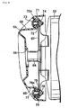
Fig. 4 is a cross-sectional view taken along the line 4-4 inFig. 3 . -
Fig. 5 is a cross-sectional view taken along the line 5-5 inFig.3 . -
Fig. 6 is a cross-sectional view taken along the line 6-6 inFig. 3 . -
Fig. 7 is a view on arrow 7 inFig. 3 . -
Fig. 8 is a cross-sectional view taken along the line 8-8 inFig. 7 . -
Fig. 9 is a cross-sectional view taken along the line 9-9 inFig. 7 . -
Fig. 10 is an enlarged cross-sectional view taken along the line 10-10 in -
Fig. 1 . -
Fig. 11 is a view onarrow 11 inFig. 10 . - Hereinbelow, a mode for carrying out the present invention will be described using an embodiment of the present invention illustrated in accompanying drawings.
-
Fig. 1 andFig. 2 show a low-floor scooter-type motorcycle with afloor 11. A body frame F that the motorcycle has includes ahead pipe 13, which rotatably supports a steerablefront fork 12, which, in turn, pivotally supports a front wheel WF. The body frame F also includes a right and left pair of side frames 14..., each of which has a front end portion joined to thehead pipe 13. Eachside frame 14 is formed by bending a single pipe, and thus includes, as a unit, adown frame portion 14a, alower frame portion 14b, a risingframe portion 14c, and aseat rail portion 14d. The downframe portion 14a droops down from thehead pipe 13. Thelower frame portion 14b is formed as extending from the bottom end of thedown frame portion 14a and then rearwards under thefloor 11. The rear half of thelower frame portion 14b is formed so as to be inclined upward to the rear. The risingframe portion 14c extends from the rear end of thelower frame portion 14b, and rises upward at a position behind thefloor 11. Theseat rail portion 14d extends rearward from the rear end of the risingframe portion 14c so as to support a ridingseat 15. - In each of the side frames 14..., a
rear sub-frame 16 is provided between a rear portion of thelower frame portion 14b and a front portion of theseat rail portion 14d. Eachrear sub-frame 16 is positioned below theseat rail portion 14d and at the rear of the risingframe portion 14c. Each ofpivot plates 17... is provided between each of the two side frames 14... and the corresponding one of therear sub-frames 16.... - The
pivot plates 17... provided to the body frame F support the power unit P with alink mechanism 18 so as to swing up and down. The power unit P includes an engine E, which is placed in front of a rear wheel WR, and also includes a transmission system M, which is placed on the left side of the rear wheel WR. The rear wheel WR is pivotally supported by a rear portion of the power unit P. The transmission system M includes a V-belt continuously variable transmission (not illustrated) and a reduction gear train (not illustrated), which transmits the power outputted from the continuously variable transmission to the axle of the rear wheel WR while reduces the speed of the outputted. - The engine E is a single-cylinder water-cooling four-cycle engine. A crankcase 20 (see
Fig. 3 ) forms a part of anengine body 19 of the engine E includes. Atransmission case 23 is provided contiguously to thecrankcase 20, and extends to the left side of the rear wheel WR. The transmission system M is housed in thetransmission case 23. Aswing arm 34 is fixed to thecrankcase 20, and extends to the right side of the rear wheel WR. Theswing arm 34 pivotally supports the rear wheel WR together with thetransmission case 23 of the power unit P. Each ofRear cushion units seat rail portions 14d... and each one of a rear portion of thetransmission case 23 and a rear portion of theswing arm 34. - A
body cover 25 of a synthetic resin is provided to cover a part of theengine body 19 and the body frame F, and thefloor 11 is formed in thebody cover 25. As has been described thus far, the body of a scooter-type vehicle with a sporty, light-weighted image is formed by the simple body frame F and thebody cover 25 to cover a relatively small area. - An
air cleaner 27 is placed above and supported by thetransmission case 23. The upstream end of aninlet pipe 28 is connected to theair cleaner 27. Athrottle body 29 is provided between the downstream end of theinlet pipe 28 and acylinder head 22 of theengine body 19. Afuel injection valve 30 is attached to thecylinder head 22 to inject the fuel into the air passing through thethrottle body 29. - Now, refer also to
Fig. 3 . Anexhaust pipe 32 extends from a right-side lower portion of thecrankcase 20 to the right side of the rear wheel WR. Theexhaust pipe 32 has an upstream end connected to the lower side surface of thecylinder head 22 while the downstream end of theexhaust pipe 32 is connected to anexhaust muffler 33. Theexhaust muffler 33 is placed in a position such that theswing arm 34 is interposed between theexhaust muffler 33 and the rear wheel WR. Theexhaust muffler 33 is fastened to theswing arm 34 withbolts 35... at a position in the upper portion of theexhaust muffler 33 and at two positions--one in front and the other in the rear with a certain interval--in the lower portion thereof. - Now, refer also to
Fig. 4 . Aprotector 37 is provided to cover the upper portion of and the outer side surface of theexhaust muffler 33. Theprotector 37 is composed of afirst protector member 38, which is made of a metal, and asecond protector member 39, which is made of a synthetic resin. - The
first protector member 38 is formed to cover at least the outer side surface of theexhaust muffler 33. Thefirst protector member 38 of this embodiment is formed to cover the outer side surface of theexhaust muffler 33, and is made of a stainless steel, for example. Thesecond protector member 39, on the other hand, is formed to cover thefirst protector member 38 from the outside while the upper portion of thefirst protector member 38 is left uncovered so as to be exposed to the outside. Thesecond protector member 39 of this embodiment is formed to cover the lower portion of thefirst protector member 38, and is made of a synthetic resin, such as a polyamide resin that is excellent in heat resistance. - A
first bracket 40, elongated in the vertical direction, is fixed, by welding or the like, to a front portion of the outer side surface of theexhaust muffler 33. A second and athird brackets exhaust muffler 33 respectively at two positions--one in the upper and the other in the lower positions--with a certain interval, asFig. 3 shows. - A recessed
portion 47, sunk inward, is formed in thefirst protector member 38, and at a position corresponding to an upper portion of thefirst bracket 40. Arubber mount 43 is installed in the center of the recessedportion 47. Therubber mount 43 is an elastic member and has a first end that is brought into contact with the upper portion of thefirst bracket 40. Acollar 44 is inserted into therubber mount 43, and has abrim portion 44a, which is brought into contact with a second end of therubber mount 43. Abolt 46 is inserted into thecollar 44 and thefirst bracket 40, and is screwed into aweld nut 45, which is firmly attached to the inner surface side of the upper portion of thefirst bracket 40. As seen from the above, a rear portion of thefirst protector member 38 is supported in an upper portion of thefirst bracket 40 via an elastic support structure with arubber mount 43. - Now, refer to
Fig. 3 . A recessedportion 48, sunk inward, is formed in a rear portion of thefirst protector member 38, and at a portion corresponding to thesecond bracket 41. Abolt 49 is disposed at the center of the recessedportion 48, and fastens the rear portion of thefirst protector member 38 to thesecond bracket 41. In addition, an elastic support structure is provided between a rear portion of thefirst protector member 38 and thesecond bracket 41. The provided elastic support structure is similar to the structure provided to elastically support the front portion of thefirst protector member 38 at the upper portion of thefirst bracket 40. As seen from the above, a front and a rear portions of the upper portion of thefirst protector member 38 are elastically supported by an upper portion of thefirst bracket 40 and by thesecond bracket 41, both of which brackets are firmly attached to theexhaust muffler 33. - Now, refer back to
Fig. 4 . A recessedportion 50, sunk inward, is formed in a front portion of thesecond protector member 39, and at a position corresponding to a lower portion of thefirst bracket 40. Acollar 51 is installed in the center of the recessedportion 50. Thecollar 51 is brought into contact with the outer surface of the first protector member38. In addition, arubber mount 52 is installed between the first and thesecond protector members collar 51 interposed in between. Here, a first end of therubber mount 52 is brought into contact with a lower portion of thefirst bracket 40. Anothercollar 53, which has abrim portion 53a is inserted into therubber mount 52. Thebrim portion 53a is brought into contact with a second end of therubber mount 52. Abolt 55 is inserted into thecollar 53 and thefirst bracket 40, and is screwed into aweld nut 54, which is firmly attached to the inner surface side of the lower portion of thefirst bracket 40. As seen from the above, thebolt 55 is used commonly to fasten both the front portion of thesecond protector member 39 and the front portion of thefirst protector member 38, which front portion is covered with thesecond protector member 39. The two portions thus fastened together are elastically supported by the lower portion of thefirst bracket 40. - Now, refer to
Fig. 3 . A recessedportion 56, sunk inward, is formed in a rear portion of thesecond protector member 39, and at a portion corresponding to thethird bracket 42. Abolt 57 is used commonly to fasten both the rear portions of the respective first andsecond protector members third bracket 42. In addition, an elastic support structure is provided between thethird bracket 42 and the rear portions of the respective first andsecond protector members second protector members first bracket 40. As seen from the above, the second protector member is supported by theexhaust muffler 33 by being fastened together with thefirst protector member 38 to theexhaust muffler 33. - Now, refer to
Fig. 5 . A support-plate portion 38a is formed integrally with thefirst protector member 38 so as to protrude forward from a front portion of thefirst protector member 38. An attachment-plate portion 39a is formed in the inner surface of thesecond protector member 39, and is formed integrally with thesecond protector member 39. The attachment-plate portion is opposed to the support-plate portion 38a from the outer side. In addition, anut 58 is attached to the attachment-plate portion 39a, and ascrew member 59, which is inserted into the respective support-plate portion 38a and attachment-plate portion 39a, is screwed into thenut 58. - Now, refer also to
Fig. 6 . A recessedportion 62 is formed in a front portion of thesecond protector member 39 with its depth gradually becoming shallower to the front. Astep portion 62, which faces forward, is formed at the rear end of the recessedportion 62. A traveling-wind introduction port 61 is formed in thestep portion 62a, and guides the traveling wind towards the outer side surface of theexhaust muffler 33 or towards thefirst protector member 38. - Now, refer also to
Fig. 7 andFig. 8 . Atail pipe 64 is formed in theexhaust muffler 33 so as to protrude rearward from a center portion of the rear end of theexhaust muffler 33. A tail-pipe cover 65 is attached to theexhaust muffler 33. The tail-pipe cover 65, with an openingportion 66 facing the rear end of thetail pipe 64, covers the rear end of theexhaust muffler 33 and thetail pipe 64. The tail-pipe cover is made of a synthetic resin, such as a polyamide resin that is excellent in heat resistance. - A
fourth bracket 67 is firmly attached, by welding or the like, to the rear end of themuffler 33. A recessedportion 68, sunk inward, is formed in the tail-pipe cover 64, above thetail pipe 64, and at a position corresponding to an upper portion of thefourth bracket 67. Arubber mount 71 is installed in the center of the recessedportion 68. Therubber mount 71 has a first end that is brought into contact with the upper portion of thefourth bracket 67. Acollar 72 is inserted into therubber mount 71, and has abrim portion 72a, which is brought into contact with a second end of therubber mount 71. Abolt 73 is inserted into thecollar 72 and thefourth bracket 67, and is screwed into aweld nut 74, which is firmly attached to the inner surface side of the upper portion of thefourth bracket 67. As seen from the above, the upper portion of the tail-pipe cover 64 is supported by the upper portion of thefourth bracket 67 via an elastic support structure with arubber mount 71. - A recessed
portion 69, sunk inward, is formed in the tail-pipe cover 64, below thetail pipe 64, and at a position corresponding to a lower portion of thefourth bracket 67. Arubber mount 75 is installed in the center of the recessedportion 69. Therubber mount 75 has a first end that is brought into contact with the lower portion of thefourth bracket 67. Acollar 76 is inserted into therubber mount 75, and has abrim portion 76a, which is brought into contact with a second end of therubber mount 75. Abolt 77 is inserted into thecollar 76 and thefourth bracket 67, and is screwed into aweld nut 78, which is firmly attached to the inner surface side of the lower portion of thefourth bracket 67. As seen from the above, the lower portion of the tail-pipe cover 64 is supported by the lower portion of thefourth bracket 67 via an elastic support structure with arubber mount 75. - In addition, a recessed
portion 70, sunk inward, is formed in the tail-pipe cover 65, and at a portion positioned on the right side of thetail pipe 64 when viewed towards the front in the traveling direction of the motorcycle. A bolt is disposed at the center of the recessedportion 70, and fastens the tail-pipe cover 65 to thefourth bracket 67. In addition, an elastic support structure is provided between thefourth bracket 67 and a portion of the tail-pipe cover 65, which portion is located at the right side of thetail pipe 64. The provided elastic support structure is similar to the elastic support structures provided to each of the upper and the lower portions of thefourth bracket 67. As seen from the above, thefourth bracket 67, which is firmly attached to the rear end of theexhaust muffler 33, elastically supports the tail-pipe cover 65. - Now, refer also to
Fig. 9 . An attachment-plate portion 39b, stretching vertically, is formed in the inner surface of a rear portion of thesecond protector member 39 within theprotector 37, and is formed integrally with thesecond protector member 39. A support-plate portion 65a is formed integrally with the tail-pipe cover 65 so as to be opposed to the attachment-plate portion 39b from the rear side. In addition, nuts 80... are attached to each of the upper and the lower portions of the support-plate portion 65a.Screw members 81..., which are inserted into respective upper and lower portions of each of the attachment-plate portion 39b and of the support-plate portion 65a and, are screwed into the corresponding nuts 58. In this way, the lower portion of thesecond protector member 39 is elastically supported by the rear end of theexhaust muffler 33 with the tail-pipe cover 65. - Incidentally, as
Fig. 1 shows, a part of theexhaust pipe 32 extending to the right side of the rear wheel WR from the right-side lower portion of thecrankcase 20 is disposed as being exposed from thebody cover 25. Within theexhaust pipe 32, the part exposed from thebody cover 25 is covered with an exhaust-pipe protector 83 made of a synthetic resin. AsFig. 10 andFig. 11 show, the exhaust-pipe protector 83 is fastened, bybolts crankcase 20 of theengine body 19, for example at two positions--one in front and the other at the rear--with a certain interval in between. - Subsequently, some of the advantageous effects of this embodiment will be described. The
protector 37, which covers the outer side surface of theexhaust muffler 33, is composed of the first and thesecond protector members first protector member 38 covers at least the outer side surface of theexhaust muffler 33. On the other hand, thesecond protector member 39, made of a synthetic resin, covers thefirst protector member 38 from the outer side while the upper portion of thefirst protector member 38 is left uncovered and thus exposed to the outside. Accordingly, by exposing the upper portion of the metallicfirst protector member 38 to the outside, favorable heat radiation can be accomplished. Meanwhile, thesecond protector member 39, made of a synthetic resin, covers thefirst protector member 38 from the outer side, and thus excellent heat insulating property can be obtained. Taking advantage of metals and synthetic resins, the heat from theexhaust muffler 33 can be blocked as the protector has an excellent heat insulating property. In addition, a higher durability of thefirst protector member 38 is accomplished. Moreover, the exposed upper portion of thefirst protector member 38 with metallic luster gives a classy impression to theprotector 37, and improves the external appearance of theprotector 37. On the other hand, within theprotector 37, the lower portion of a part that is visible from the outside is composed of thesecond protector member 39, which is made of a synthetic resin and which is thus not glossy. Consequently, the lower portion of theprotector 37 can be made a low profile, so that theexhaust muffler 33 can be made to look not as big as it really is. - In addition, the first and the
second protector members exhaust muffler 33 withbolts second protector members exhaust muffler 33, and this can contribute to a reduction in the number of component parts. - Moreover, the first and the
second protector members exhaust muffler 33 with rubber mounts 43,52 interposed in between respectively. Consequently, the vibration that might be transmitted from theexhaust muffler 33 to theprotector 37 side can be reduced, and generation of the noise due to the vibration can also be reduced. In addition, the amount of heat transferred, by heat conduction, from theexhaust muffler 33 to theprotector 37 can also be made smaller. - The traveling-
wind introduction port 61 is formed in thesecond protector member 39 to guide the traveling wind towards the outer side surface of theexhaust muffler 33 or towards thefirst protector member 38. Consequently, the traveling wind introduced into theprotector 37 can be used to effectively cool down themetallic exhaust muffler 33 or the metallicfirst protector member 38. Thus, an improved cooling efficiency can be accomplished. - Moreover, the
tail pipe 64 is formed in theexhaust muffler 33 and protrudes rearward from the rear end of theexhaust muffler 33, meanwhile the tail-pipe cover 65, which is made of a synthetic resin, and which covers the rear end of theexhaust muffler 33 and thetail pipe 64, is attached to theexhaust muffler 33. Consequently, the heat from thetail pipe 64 and the rear end portion of theexhaust muffler 33 can be blocked by the tail-pipe cover 65. - Furthermore, within the
exhaust pipe 32, the portion exposed from thebody cover 25 is covered with theexhaust pipe protector 83. Consequently, the heat from theexhaust pipe 32 is blocked from radiating to the outside. - An embodiment of the present invention has been described thus far. The present invention is not limited to the embodiment described thus far, and various modifications can be made without departing from the invention defined by the claims.
- In an exhaust system of a motorcycle in which an
exhaust muffler 33 is connected to anexhaust pipe 32 extending from acylinder head 22 of anengine body 19, and in which the outer side surface of theexhaust muffler 33 is covered with aprotector 37, an excellent durability and appearance are to be accomplished, and an excellent heat resistance property is to be accomplished to block the heat from theexhaust muffler 33. The invention now provides aprotector 37 composed of afirst protector member 38 and a second protector member (39). The metallicfirst protector member 38 covers at least the outer side surface of anexhaust muffler 33. Thesecond protector member 39, which is made of a synthetic resin, covers thefirst protector member 38 from the outer side while an upper portion of thefirst protector member 38 is left uncovered so as to be exposed to the outside.
Claims (5)
- An exhaust system for a motorcycle comprising:an exhaust muffler (33) connected to an exhaust pipe (32) extending from a cylinder head (22) of an engine body (19), anda protector (37), at least partially covering the outside of the exhaust muffler (33),
wherein the protector (37) includes:a first protector member (38), which covers the outer side surface of the exhaust muffler (33); anda second protector member (39), which covers the first protector member (38) from the outer side;
wherein the first (38) and the second (39) protector members are fastened together to, and supported by, the exhaust muffler (33),
characterized in thatthe first protector member (38) is made of a metal and additionally to the outer side surface covers the upper portion of the exhaust muffler (33),the second protector member (39) is made of a synthetic resin and covers the first protector member (38) from the outer side while leaving the portion of the first protector member (38) covering the upper portion of the exhaust muffler (33) uncovered so as to be exposed to the outside, anda traveling-wind introduction port (61) is formed in the second protector member (39) so as to guide the traveling wind towards any one of the outer surface of the exhaust muffler (33) and the first protector member (38), whereinsaid traveling-wind introduction port (61) is located forward the portion that the first and the second protector members (38, 39) are fastened together to. - The exhaust system for a motorcycle according to claim 1 wherein the first (38) and the second (39) protector members are supported by the exhaust muffler (33) with respective elastic members (43, 52) interposed in between.
- The exhaust system for a motorcycle according to any one of claims 1 to 2, wherein a tail pipe (64) is formed in the exhaust muffler (33) so as to protrude rearward from the rear end of the exhaust muffler, and a tail-pipe cover (65), which is made of a synthetic resin, and which covers the rear end of the exhaust muffler (33) and the tail pipe (64), is attached to the exhaust muffler (33).
- The exhaust system for a motorcycle according to any one of claims 1 to 3, characterized in that, within the exhaust pipe (32), a part exposed from a body cover is covered with an exhaust-pipe protector (83).
- The exhaust system for a motorcycle according to any one of claims 1 to 4, wherein the first and the second protector members (38, 39) are brought into contact with each other with a collar (51) interposed in between.
Applications Claiming Priority (1)
| Application Number | Priority Date | Filing Date | Title |
|---|---|---|---|
| JP2006274720A JP4700586B2 (en) | 2006-10-06 | 2006-10-06 | Motorcycle exhaust system |
Publications (2)
| Publication Number | Publication Date |
|---|---|
| EP1911945A1 EP1911945A1 (en) | 2008-04-16 |
| EP1911945B1 true EP1911945B1 (en) | 2011-02-02 |
Family
ID=38710508
Family Applications (1)
| Application Number | Title | Priority Date | Filing Date |
|---|---|---|---|
| EP20070018317 Active EP1911945B1 (en) | 2006-10-06 | 2007-09-18 | Exhaust system for motorcycle |
Country Status (3)
| Country | Link |
|---|---|
| EP (1) | EP1911945B1 (en) |
| JP (1) | JP4700586B2 (en) |
| CN (1) | CN100593075C (en) |
Families Citing this family (19)
| Publication number | Priority date | Publication date | Assignee | Title |
|---|---|---|---|---|
| JP2009264293A (en) * | 2008-04-25 | 2009-11-12 | Yamaha Motor Co Ltd | Vehicle and muffler protector unit |
| JP5315072B2 (en) | 2009-01-30 | 2013-10-16 | 本田技研工業株式会社 | Muffler cover for saddle-ride type vehicles |
| JP2012254750A (en) * | 2011-06-10 | 2012-12-27 | Yamaha Motor Co Ltd | Muffler protector and saddle-ride type vehicle |
| JP5867852B2 (en) * | 2011-09-21 | 2016-02-24 | 本田技研工業株式会社 | Muffler device with protector for small vehicles |
| KR101284328B1 (en) * | 2011-12-08 | 2013-07-08 | 현대자동차주식회사 | Muffler for vehicle |
| JP5911336B2 (en) * | 2012-02-27 | 2016-04-27 | 本田技研工業株式会社 | Small vehicle |
| JP5827595B2 (en) | 2012-05-18 | 2015-12-02 | 本田技研工業株式会社 | Muffler device for saddle riding type vehicle |
| CN102733920A (en) * | 2012-06-28 | 2012-10-17 | 力帆实业(集团)股份有限公司 | Silencer assembly of motorcycle |
| JP5847051B2 (en) * | 2012-09-28 | 2016-01-20 | 本田技研工業株式会社 | Exhaust device for saddle riding type vehicle |
| JP6446206B2 (en) * | 2014-09-01 | 2018-12-26 | 川崎重工業株式会社 | Vehicle cover structure |
| JP6236700B2 (en) * | 2014-09-30 | 2017-11-29 | 本田技研工業株式会社 | Silencer structure for saddle-ride type vehicles |
| TWI593871B (en) * | 2015-11-24 | 2017-08-01 | Kwang Yang Motor Co | Engine exhaust pipe cover fixed structure |
| CN105508024A (en) * | 2015-11-30 | 2016-04-20 | 宁波大叶园林设备有限公司 | Double-layered cooling and noise-elimination two-stroke LPG engine with lengthened and enlarged wrapping resin |
| DE102016113231A1 (en) * | 2016-07-19 | 2018-01-25 | Eberspächer Exhaust Technology GmbH & Co. KG | Nozzle assembly, in particular for an exhaust treatment arrangement of an exhaust system of an internal combustion engine |
| JP6752973B2 (en) * | 2017-07-28 | 2020-09-09 | 本田技研工業株式会社 | Muffler cover structure for saddle-riding vehicles |
| CN110017204B (en) * | 2017-11-15 | 2021-11-19 | 本田技研工业株式会社 | Mounting structure of end cover |
| JP6648197B2 (en) * | 2018-06-26 | 2020-02-14 | 本田技研工業株式会社 | Exhaust system for motorcycle |
| JP7215330B2 (en) | 2019-05-28 | 2023-01-31 | スズキ株式会社 | Exhaust system and straddle-type vehicle |
| JP7245349B2 (en) * | 2019-09-26 | 2023-03-23 | 本田技研工業株式会社 | Straddle-type vehicle exhaust system |
Family Cites Families (8)
| Publication number | Priority date | Publication date | Assignee | Title |
|---|---|---|---|---|
| JP3010874B2 (en) | 1992-01-31 | 2000-02-21 | スズキ株式会社 | Auxiliary equipment support structure for motorcycles |
| JP3511744B2 (en) * | 1995-08-10 | 2004-03-29 | スズキ株式会社 | Engine working machine |
| JPH10121957A (en) * | 1996-10-14 | 1998-05-12 | Suzuki Motor Corp | Heat insulation cover for vehicle exhaust device |
| JP2989792B2 (en) * | 1997-12-16 | 1999-12-13 | 川崎重工業株式会社 | Exhaust muffler for motorcycle and method of manufacturing the same |
| JP2001073758A (en) | 1999-08-31 | 2001-03-21 | Yamaha Motor Co Ltd | Muffler of two-wheeled vehicle |
| JP2005083286A (en) * | 2003-09-09 | 2005-03-31 | Honda Motor Co Ltd | Exhaust apparatus |
| JP2006044633A (en) * | 2004-03-19 | 2006-02-16 | Yamaha Motor Co Ltd | Riding type vehicle |
| JP4400823B2 (en) * | 2004-06-01 | 2010-01-20 | 本田技研工業株式会社 | Muffler device for motorcycles |
-
2006
- 2006-10-06 JP JP2006274720A patent/JP4700586B2/en not_active Expired - Fee Related
-
2007
- 2007-09-18 EP EP20070018317 patent/EP1911945B1/en active Active
- 2007-09-24 CN CN200710161807A patent/CN100593075C/en not_active Expired - Fee Related
Also Published As
| Publication number | Publication date |
|---|---|
| JP2008095509A (en) | 2008-04-24 |
| JP4700586B2 (en) | 2011-06-15 |
| CN100593075C (en) | 2010-03-03 |
| EP1911945A1 (en) | 2008-04-16 |
| CN101158304A (en) | 2008-04-09 |
Similar Documents
| Publication | Publication Date | Title |
|---|---|---|
| EP1911945B1 (en) | Exhaust system for motorcycle | |
| JP2008095509A5 (en) | ||
| US8016321B2 (en) | Straddle type vehicle | |
| EP2028095A2 (en) | Motorcycle | |
| US8051938B2 (en) | Seat mounting structure for motorcycle, and motorcycle incorporating same | |
| KR100568097B1 (en) | Exhaust valve control device for motorcycle | |
| US20140174581A1 (en) | Exhaust pipe cover structure for saddle-ride type vehicle | |
| JP6130119B2 (en) | Motorcycle | |
| EP2562069A2 (en) | Saddle-riding type automotive vehicle | |
| JP2006123656A (en) | Saddle riding type vehicle | |
| EP2077221B1 (en) | Straddle-type vehicle | |
| JP6192913B2 (en) | Saddle riding vehicle | |
| CN110015368B (en) | Saddle type riding vehicle | |
| EP2711277B1 (en) | Frame structure for saddle-riding type automotive vehicle | |
| CN108626019B (en) | Vehicle structure for mounting air-cooled internal combustion engine | |
| JP3793172B2 (en) | Mounting structure for engine coolant for motorcycles | |
| JP6721640B2 (en) | Muffler for saddle type vehicles | |
| JP2005225383A (en) | Lower structure of motorcycle body | |
| JP7238008B2 (en) | saddle-riding vehicle | |
| JP7238007B2 (en) | saddle-riding vehicle | |
| JP2013174202A (en) | Saddle-type vehicle | |
| JP7216134B2 (en) | saddle-riding vehicle | |
| JP7252274B2 (en) | saddle-riding vehicle | |
| JP6147534B2 (en) | Saddle riding vehicle | |
| JP2023030500A (en) | Saddle-riding type vehicle |
Legal Events
| Date | Code | Title | Description |
|---|---|---|---|
| PUAI | Public reference made under article 153(3) epc to a published international application that has entered the european phase |
Free format text: ORIGINAL CODE: 0009012 |
|
| 17P | Request for examination filed |
Effective date: 20070918 |
|
| AK | Designated contracting states |
Kind code of ref document: A1 Designated state(s): AT BE BG CH CY CZ DE DK EE ES FI FR GB GR HU IE IS IT LI LT LU LV MC MT NL PL PT RO SE SI SK TR |
|
| AX | Request for extension of the european patent |
Extension state: AL BA HR MK RS |
|
| AKX | Designation fees paid |
Designated state(s): FR IT |
|
| REG | Reference to a national code |
Ref country code: DE Ref legal event code: 8566 |
|
| GRAP | Despatch of communication of intention to grant a patent |
Free format text: ORIGINAL CODE: EPIDOSNIGR1 |
|
| RIC1 | Information provided on ipc code assigned before grant |
Ipc: F01N 13/08 20100101ALI20100621BHEP Ipc: F01N 13/14 20100101AFI20100621BHEP |
|
| GRAS | Grant fee paid |
Free format text: ORIGINAL CODE: EPIDOSNIGR3 |
|
| GRAA | (expected) grant |
Free format text: ORIGINAL CODE: 0009210 |
|
| RAP1 | Party data changed (applicant data changed or rights of an application transferred) |
Owner name: HONDA MOTOR CO., LTD. |
|
| AK | Designated contracting states |
Kind code of ref document: B1 Designated state(s): FR IT |
|
| PLBE | No opposition filed within time limit |
Free format text: ORIGINAL CODE: 0009261 |
|
| STAA | Information on the status of an ep patent application or granted ep patent |
Free format text: STATUS: NO OPPOSITION FILED WITHIN TIME LIMIT |
|
| 26N | No opposition filed |
Effective date: 20111103 |
|
| REG | Reference to a national code |
Ref country code: FR Ref legal event code: PLFP Year of fee payment: 10 |
|
| REG | Reference to a national code |
Ref country code: FR Ref legal event code: PLFP Year of fee payment: 11 |
|
| REG | Reference to a national code |
Ref country code: FR Ref legal event code: PLFP Year of fee payment: 12 |
|
| PGFP | Annual fee paid to national office [announced via postgrant information from national office to epo] |
Ref country code: FR Payment date: 20180813 Year of fee payment: 12 |
|
| PG25 | Lapsed in a contracting state [announced via postgrant information from national office to epo] |
Ref country code: FR Free format text: LAPSE BECAUSE OF NON-PAYMENT OF DUE FEES Effective date: 20190930 |
|
| PGFP | Annual fee paid to national office [announced via postgrant information from national office to epo] |
Ref country code: IT Payment date: 20230810 Year of fee payment: 17 |