JP2019190355A - Saddle riding-type vehicle - Google Patents
Saddle riding-type vehicle Download PDFInfo
- Publication number
- JP2019190355A JP2019190355A JP2018083218A JP2018083218A JP2019190355A JP 2019190355 A JP2019190355 A JP 2019190355A JP 2018083218 A JP2018083218 A JP 2018083218A JP 2018083218 A JP2018083218 A JP 2018083218A JP 2019190355 A JP2019190355 A JP 2019190355A
- Authority
- JP
- Japan
- Prior art keywords
- cover
- vehicle
- sensor
- oxygen sensor
- width direction
- Prior art date
- Legal status (The legal status is an assumption and is not a legal conclusion. Google has not performed a legal analysis and makes no representation as to the accuracy of the status listed.)
- Pending
Links
Images


Classifications
-
- F—MECHANICAL ENGINEERING; LIGHTING; HEATING; WEAPONS; BLASTING
- F01—MACHINES OR ENGINES IN GENERAL; ENGINE PLANTS IN GENERAL; STEAM ENGINES
- F01N—GAS-FLOW SILENCERS OR EXHAUST APPARATUS FOR MACHINES OR ENGINES IN GENERAL; GAS-FLOW SILENCERS OR EXHAUST APPARATUS FOR INTERNAL COMBUSTION ENGINES
- F01N1/00—Silencing apparatus characterised by method of silencing
-
- F—MECHANICAL ENGINEERING; LIGHTING; HEATING; WEAPONS; BLASTING
- F01—MACHINES OR ENGINES IN GENERAL; ENGINE PLANTS IN GENERAL; STEAM ENGINES
- F01N—GAS-FLOW SILENCERS OR EXHAUST APPARATUS FOR MACHINES OR ENGINES IN GENERAL; GAS-FLOW SILENCERS OR EXHAUST APPARATUS FOR INTERNAL COMBUSTION ENGINES
- F01N13/00—Exhaust or silencing apparatus characterised by constructional features ; Exhaust or silencing apparatus, or parts thereof, having pertinent characteristics not provided for in, or of interest apart from, groups F01N1/00 - F01N5/00, F01N9/00, F01N11/00
- F01N13/008—Mounting or arrangement of exhaust sensors in or on exhaust apparatus
-
- F—MECHANICAL ENGINEERING; LIGHTING; HEATING; WEAPONS; BLASTING
- F01—MACHINES OR ENGINES IN GENERAL; ENGINE PLANTS IN GENERAL; STEAM ENGINES
- F01P—COOLING OF MACHINES OR ENGINES IN GENERAL; COOLING OF INTERNAL-COMBUSTION ENGINES
- F01P11/00—Component parts, details, or accessories not provided for in, or of interest apart from, groups F01P1/00 - F01P9/00
- F01P11/10—Guiding or ducting cooling-air, to, or from, liquid-to-air heat exchangers
-
- F—MECHANICAL ENGINEERING; LIGHTING; HEATING; WEAPONS; BLASTING
- F01—MACHINES OR ENGINES IN GENERAL; ENGINE PLANTS IN GENERAL; STEAM ENGINES
- F01P—COOLING OF MACHINES OR ENGINES IN GENERAL; COOLING OF INTERNAL-COMBUSTION ENGINES
- F01P5/00—Pumping cooling-air or liquid coolants
- F01P5/02—Pumping cooling-air; Arrangements of cooling-air pumps, e.g. fans or blowers
- F01P5/06—Guiding or ducting air to, or from, ducted fans
-
- F—MECHANICAL ENGINEERING; LIGHTING; HEATING; WEAPONS; BLASTING
- F01—MACHINES OR ENGINES IN GENERAL; ENGINE PLANTS IN GENERAL; STEAM ENGINES
- F01N—GAS-FLOW SILENCERS OR EXHAUST APPARATUS FOR MACHINES OR ENGINES IN GENERAL; GAS-FLOW SILENCERS OR EXHAUST APPARATUS FOR INTERNAL COMBUSTION ENGINES
- F01N2260/00—Exhaust treating devices having provisions not otherwise provided for
- F01N2260/20—Exhaust treating devices having provisions not otherwise provided for for heat or sound protection, e.g. using a shield or specially shaped outer surface of exhaust device
-
- F—MECHANICAL ENGINEERING; LIGHTING; HEATING; WEAPONS; BLASTING
- F01—MACHINES OR ENGINES IN GENERAL; ENGINE PLANTS IN GENERAL; STEAM ENGINES
- F01N—GAS-FLOW SILENCERS OR EXHAUST APPARATUS FOR MACHINES OR ENGINES IN GENERAL; GAS-FLOW SILENCERS OR EXHAUST APPARATUS FOR INTERNAL COMBUSTION ENGINES
- F01N2560/00—Exhaust systems with means for detecting or measuring exhaust gas components or characteristics
- F01N2560/02—Exhaust systems with means for detecting or measuring exhaust gas components or characteristics the means being an exhaust gas sensor
- F01N2560/025—Exhaust systems with means for detecting or measuring exhaust gas components or characteristics the means being an exhaust gas sensor for measuring or detecting O2, e.g. lambda sensors
-
- F—MECHANICAL ENGINEERING; LIGHTING; HEATING; WEAPONS; BLASTING
- F01—MACHINES OR ENGINES IN GENERAL; ENGINE PLANTS IN GENERAL; STEAM ENGINES
- F01N—GAS-FLOW SILENCERS OR EXHAUST APPARATUS FOR MACHINES OR ENGINES IN GENERAL; GAS-FLOW SILENCERS OR EXHAUST APPARATUS FOR INTERNAL COMBUSTION ENGINES
- F01N2590/00—Exhaust or silencing apparatus adapted to particular use, e.g. for military applications, airplanes, submarines
- F01N2590/04—Exhaust or silencing apparatus adapted to particular use, e.g. for military applications, airplanes, submarines for motorcycles
-
- F—MECHANICAL ENGINEERING; LIGHTING; HEATING; WEAPONS; BLASTING
- F01—MACHINES OR ENGINES IN GENERAL; ENGINE PLANTS IN GENERAL; STEAM ENGINES
- F01N—GAS-FLOW SILENCERS OR EXHAUST APPARATUS FOR MACHINES OR ENGINES IN GENERAL; GAS-FLOW SILENCERS OR EXHAUST APPARATUS FOR INTERNAL COMBUSTION ENGINES
- F01N2900/00—Details of electrical control or of the monitoring of the exhaust gas treating apparatus
- F01N2900/06—Parameters used for exhaust control or diagnosing
- F01N2900/14—Parameters used for exhaust control or diagnosing said parameters being related to the exhaust gas
- F01N2900/1402—Exhaust gas composition
-
- F—MECHANICAL ENGINEERING; LIGHTING; HEATING; WEAPONS; BLASTING
- F01—MACHINES OR ENGINES IN GENERAL; ENGINE PLANTS IN GENERAL; STEAM ENGINES
- F01P—COOLING OF MACHINES OR ENGINES IN GENERAL; COOLING OF INTERNAL-COMBUSTION ENGINES
- F01P2050/00—Applications
- F01P2050/16—Motor-cycles
Abstract
Description
本発明は鞍乗型車両に関する。 The present invention relates to a saddle riding type vehicle.
従来から、排ガスの酸素濃度を検出する酸素センサを備えた鞍乗型車両が知られている。酸素センサは、例えばジルコニア等の素材を含むセンサ素子を有している。酸素濃度を精度良く検出するためには、センサ素子の温度を所定の活性温度に維持する必要がある。 Conventionally, a saddle-ride type vehicle equipped with an oxygen sensor for detecting the oxygen concentration of exhaust gas is known. The oxygen sensor has a sensor element including a material such as zirconia. In order to detect the oxygen concentration with high accuracy, it is necessary to maintain the temperature of the sensor element at a predetermined activation temperature.
特許文献1には、排気管のファンカバーよりも後方の部分に酸素センサが取り付けられた自動二輪車が記載されている。ファンカバーの内側にはファンが設けられ、ファンカバーには空気を導入する開口が形成されている。 Patent Document 1 describes a motorcycle in which an oxygen sensor is attached to a rear portion of a fan cover of an exhaust pipe. A fan is provided inside the fan cover, and an opening for introducing air is formed in the fan cover.
酸素センサがエンジンの燃焼室の近くに設けられていると、燃焼室からの高温の排ガスによりセンサ素子を早期に暖めることができる。また、センサ素子を所定の温度に維持することが容易となる。しかし、特許文献1に開示されているように、酸素センサの配置を考えたときに酸素センサを燃焼室から遠い位置に設けなければならない場合がある。この場合、燃焼室からの熱の影響が小さくなり、酸素センサのセンサ素子を暖めるのに時間がかかる。また、センサ素子の温度を安定して維持しにくい。そこで、特許文献1に開示された自動二輪車において、センサ素子を加熱するヒータを内蔵した酸素センサを用いることが考えられる。 If the oxygen sensor is provided near the combustion chamber of the engine, the sensor element can be warmed early by the high-temperature exhaust gas from the combustion chamber. Further, it becomes easy to maintain the sensor element at a predetermined temperature. However, as disclosed in Patent Document 1, there are cases where the oxygen sensor needs to be provided at a position far from the combustion chamber when the arrangement of the oxygen sensor is considered. In this case, the influence of heat from the combustion chamber is reduced, and it takes time to warm the sensor element of the oxygen sensor. Further, it is difficult to stably maintain the temperature of the sensor element. Therefore, in the motorcycle disclosed in Patent Document 1, it is conceivable to use an oxygen sensor incorporating a heater for heating the sensor element.
ところで、自動二輪車の走行に伴い、自動二輪車には前方から後方に向かって風が流れる。以下、この風のことを「走行風」という。ファンカバーには空気を導入する開口が形成されているが、自動二輪車の走行中に空気を導入しやすいよう、ファンカバーは走行風が通る位置に設けられている。そのため、ファンカバーの近傍に酸素センサが配置されている場合、酸素センサは走行風によって冷却されやすい。したがって、酸素センサがヒータを内蔵していたとしても、酸素センサの検出精度が低下するおそれがある。 By the way, with the traveling of the motorcycle, wind flows from the front to the rear of the motorcycle. Hereinafter, this wind is referred to as “running wind”. Although an opening for introducing air is formed in the fan cover, the fan cover is provided at a position where the traveling wind passes so that air can be easily introduced during traveling of the motorcycle. Therefore, when the oxygen sensor is disposed in the vicinity of the fan cover, the oxygen sensor is easily cooled by the traveling wind. Therefore, even if the oxygen sensor has a built-in heater, the detection accuracy of the oxygen sensor may be reduced.
本発明はかかる点に鑑みてなされたものであり、その目的は、ファンカバーより後方に配置された酸素センサを備えた鞍乗型車両において、走行風によって酸素センサが冷却されることを抑制することにより、酸素センサの検出精度を良好に保つことである。 The present invention has been made in view of such a point, and an object thereof is to suppress the oxygen sensor from being cooled by traveling wind in a straddle-type vehicle provided with an oxygen sensor disposed behind the fan cover. Thus, the detection accuracy of the oxygen sensor is kept good.
本願発明者は、上記目的を達成するために、酸素センサに走行風が当たりにくいようにするセンサカバーをファンカバーに一体的に形成することとした。具体的には、ファンカバーの後部にセンサカバーを一体形成することにより、車両側面視においてセンサカバーと酸素センサの少なくとも一部とが重なるようにした。また、センサカバーの酸素センサと重なる部分を、後方に向かうに従って車幅方向の外方に突出するような形状にした。これにより、酸素センサに走行風が直接当たることを防ぎ、かつ、走行風を後方に円滑に導くことができると考えた。 In order to achieve the above object, the inventor of the present application has integrally formed a sensor cover on the fan cover that makes it difficult for the running air to hit the oxygen sensor. Specifically, the sensor cover is formed integrally with the rear part of the fan cover so that the sensor cover and at least a part of the oxygen sensor overlap in a side view of the vehicle. In addition, the portion of the sensor cover that overlaps the oxygen sensor is shaped to protrude outward in the vehicle width direction toward the rear. Thereby, it was considered that traveling air could be prevented from directly hitting the oxygen sensor and the traveling air could be smoothly guided backward.
上記の工夫により、走行風は酸素センサに直接当たらなくなった。しかし、センサカバーの後方に負圧が生じることにより、センサカバーの表面に沿って流れた後の走行風がその負圧によってセンサカバーの内側に流入し、酸素センサの周囲に流れてしまうという問題が生じることとなった。 As a result of the above measures, the running wind no longer hits the oxygen sensor directly. However, a negative pressure is generated behind the sensor cover, so that the traveling wind after flowing along the surface of the sensor cover flows into the sensor cover due to the negative pressure and flows around the oxygen sensor. Will occur.
そこで、本願発明者は、以下のように更なる検討を試みた。まず、センサカバーを後方に延長するように大型化することを検討した。しかし、センサカバーを大型化すると、センサカバーが走行風から受ける力が大きくなってしまう。そのため、センサカバー、およびセンサカバーと一体化されたファンカバーの剛性確保の観点から好ましくない。 Therefore, the inventor of the present application tried further investigation as follows. First, we examined increasing the size of the sensor cover to extend backward. However, when the sensor cover is enlarged, the force that the sensor cover receives from the traveling wind increases. Therefore, it is not preferable from the viewpoint of securing rigidity of the sensor cover and the fan cover integrated with the sensor cover.
そこで、本願発明者は、サイレンサの車幅方向の外方に設けられるサイレンサカバーに着目した。そして、センサカバーを大型化しなくても、センサカバーおよびサイレンサカバーの両方を効果的に配置することにより、センサカバーの表面に沿って流れた走行風がセンサカバーの内側に流入し難くすることができ、酸素センサが走行風により冷却され難くなることに思い至った。このような知見に基づく発明の構成は、以下の通りである。 Therefore, the inventor of the present application paid attention to the silencer cover provided outside the silencer in the vehicle width direction. And even if the sensor cover is not enlarged, it is possible to make it difficult for the traveling wind flowing along the surface of the sensor cover to flow into the inside of the sensor cover by effectively arranging both the sensor cover and the silencer cover. It was possible that the oxygen sensor would be difficult to be cooled by the traveling wind. The configuration of the invention based on such knowledge is as follows.
本発明に係る鞍乗型車両は、内燃機関と、前記内燃機関に接続された排気管と、前記排気管の後方に配置され、前記排気管に接続されたサイレンサと、前記内燃機関の車幅方向の外方に配置されたファンと、前記ファンの車幅方向の外方に配置され、開口が形成されたファンカバーと、前記サイレンサの車幅方向の外方に配置されたサイレンサカバーと、前記排気管の内部に配置されたセンサ素子と前記センサ素子を加熱するヒータとを有し、前記排気管に取り付けられた酸素センサと、前記ファンカバーと一体的に形成され、前記酸素センサよりも車幅方向の外方に位置し、車両側面視において前記酸素センサの少なくとも一部と重なり、車幅方向の外方かつ車両前後方向の後方に延びるセンサカバーと、を備える。前記サイレンサカバーは、前記酸素センサよりも車幅方向の外方に位置し、車幅方向の外方かつ車両前後方向の後方に延びる前部を有している。車両平面視において、前記センサカバーの後端と前記サイレンサカバーの前記前部の前端との間の車両前後方向の距離は、前記ファンカバーの後端と前記サイレンサの前端との間の車両前後方向の距離よりも短い。 A straddle-type vehicle according to the present invention includes an internal combustion engine, an exhaust pipe connected to the internal combustion engine, a silencer disposed behind the exhaust pipe and connected to the exhaust pipe, and a vehicle width of the internal combustion engine. A fan disposed outward in the direction, a fan cover disposed outward in the vehicle width direction of the fan and formed with an opening, and a silencer cover disposed outward in the vehicle width direction of the silencer, A sensor element disposed inside the exhaust pipe and a heater for heating the sensor element; the oxygen sensor attached to the exhaust pipe; and the fan cover; A sensor cover that is located outward in the vehicle width direction, overlaps at least a part of the oxygen sensor in a side view of the vehicle, and extends outward in the vehicle width direction and rearward in the vehicle front-rear direction. The silencer cover has a front portion that is located outward in the vehicle width direction from the oxygen sensor and extends outward in the vehicle width direction and rearward in the vehicle front-rear direction. In the vehicle plan view, the distance in the vehicle longitudinal direction between the rear end of the sensor cover and the front end of the front portion of the silencer cover is the vehicle longitudinal direction between the rear end of the fan cover and the front end of the silencer. Shorter than the distance.
上記鞍乗型車両によれば、酸素センサに走行風が直接当たることをセンサカバーにより防止しながら、センサカバーとサイレンサカバーの前部とにより、走行風が負圧により酸素センサの周囲に流れてしまうことを抑制することができる。よって、走行風によって酸素センサが冷却されることを抑制することができ、酸素センサの検出精度を良好に保つことができる。 According to the saddle-ride type vehicle, the traveling wind flows around the oxygen sensor due to the negative pressure by the sensor cover and the front part of the silencer cover while preventing the traveling wind from directly hitting the oxygen sensor. Can be suppressed. Therefore, it can suppress that an oxygen sensor is cooled with driving | running | working wind, and can maintain the detection accuracy of an oxygen sensor favorable.
本発明の好ましい一態様によれば、車両平面視において、前記サイレンサカバーの前記前部の車幅方向の内端は、前記センサカバーの車幅方向の外端よりも車幅方向の内方に位置している。 According to a preferred aspect of the present invention, in the vehicle plan view, the inner end in the vehicle width direction of the front portion of the silencer cover is more inward in the vehicle width direction than the outer end in the vehicle width direction of the sensor cover. positioned.
本発明の好ましい一態様によれば、車両平面視において、前記サイレンサカバーの前記前部の前端は、前記センサカバーの車幅方向の外端よりも車幅方向の内方に位置している。 According to a preferred aspect of the present invention, the front end of the front portion of the silencer cover is positioned more inward in the vehicle width direction than the outer end of the sensor cover in the vehicle width direction in plan view of the vehicle.
上記各態様によれば、走行風が負圧により酸素センサの周囲に流れてしまうことを更に抑制することができる。 According to each said aspect, it can further suppress that driving | running | working wind flows around the oxygen sensor by a negative pressure.
本発明の好ましい一態様によれば、車両前後方向に関して、前記サイレンサカバーの前記前部の前端は、前記センサカバーの後端と同じ位置、または、前記センサカバーの後端よりも前方に位置している。 According to a preferred aspect of the present invention, the front end of the front portion of the silencer cover is located at the same position as the rear end of the sensor cover or forward of the rear end of the sensor cover in the vehicle longitudinal direction. ing.
上記態様によれば、走行風が負圧により酸素センサの周囲に流れてしまうことを更に抑制することができる。 According to the said aspect, it can further suppress that driving | running | working wind flows into the circumference | surroundings of an oxygen sensor by a negative pressure.
本発明の好ましい一態様によれば、前記酸素センサは、前記内燃機関よりも後方に配置されている。 According to a preferred aspect of the present invention, the oxygen sensor is arranged behind the internal combustion engine.
本発明の好ましい一態様によれば、前記鞍乗型車両は、前記内燃機関により駆動される後輪を備え、前記酸素センサの少なくとも一部は、車両側面視において前記後輪と重なる位置に配置されている。 According to a preferred aspect of the present invention, the saddle riding type vehicle includes a rear wheel driven by the internal combustion engine, and at least a part of the oxygen sensor is disposed at a position overlapping the rear wheel in a side view of the vehicle. Has been.
本発明の好ましい一態様によれば、前記鞍乗型車両は、前記排気管を流れる排ガスを浄化する触媒を備え、前記酸素センサは、前記触媒よりも排ガスの流通方向の下流側に配置されている。 According to a preferred aspect of the present invention, the straddle-type vehicle includes a catalyst that purifies the exhaust gas flowing through the exhaust pipe, and the oxygen sensor is disposed downstream of the catalyst in the flow direction of the exhaust gas. Yes.
上記各態様によれば、酸素センサが内燃機関から遠い位置に配置されているので、前述の効果が顕著となる。 According to each of the above aspects, since the oxygen sensor is disposed at a position far from the internal combustion engine, the above-described effect becomes remarkable.
本発明の好ましい一態様によれば、前記センサカバーは、前記ファンカバーの前記開口よりも後方に配置されている。 According to a preferred aspect of the present invention, the sensor cover is disposed behind the opening of the fan cover.
上記態様によれば、走行風の一部をファンカバーの開口を通じてファンに供給することができ、走行風の他の一部をセンサカバーにより、酸素センサに当たらないようにしつつ後方に円滑に導くことができる。 According to the above aspect, a part of the traveling wind can be supplied to the fan through the opening of the fan cover, and the other part of the traveling wind is smoothly guided backward by the sensor cover so as not to hit the oxygen sensor. be able to.
本発明の好ましい一態様によれば、前記酸素センサは、前記排気管の外部に位置する筒状のケースを有している。車両側面視において、前記センサカバーと前記サイレンサカバーの前記前部との間の車両前後方向の最小間隔は、前記酸素センサの前記ケースの軸線方向の寸法よりも小さい。 According to a preferred aspect of the present invention, the oxygen sensor has a cylindrical case located outside the exhaust pipe. In a vehicle side view, the minimum distance in the vehicle front-rear direction between the sensor cover and the front portion of the silencer cover is smaller than the dimension of the oxygen sensor in the axial direction of the case.
上記態様によれば、センサカバーとサイレンサカバーの前部との間の車両前後方向の最小間隔が小さいので、走行風が負圧により酸素センサの周囲に流れてしまうことを更に抑制することができる。 According to the above aspect, since the minimum distance in the vehicle front-rear direction between the sensor cover and the front part of the silencer cover is small, it is possible to further suppress the traveling wind from flowing around the oxygen sensor due to negative pressure. .
本発明の好ましい一態様によれば、車両側面視において、前記センサカバーには前方に向けて凹んだ凹部が形成され、前記サイレンサカバーの前記前部には、前記凹部に向けて前方に突出する凸部が形成されている。 According to a preferred aspect of the present invention, in the vehicle side view, the sensor cover is formed with a recessed portion that is recessed forward, and the front portion of the silencer cover projects forward toward the recessed portion. Protrusions are formed.
上記態様によれば、センサカバーとサイレンサカバーの前部とは、車両側面視において互いに適合した形状に形成されている。よって、センサカバーの表面に沿って流れた走行風がセンサカバーの内側に流入することを効果的に抑制することができ、酸素センサが走行風により冷却されることを効果的に抑制することができる。 According to the said aspect, the sensor cover and the front part of a silencer cover are formed in the shape which mutually adapted in the vehicle side view. Therefore, it is possible to effectively suppress the traveling wind flowing along the surface of the sensor cover from flowing into the inside of the sensor cover, and to effectively suppress the oxygen sensor from being cooled by the traveling wind. it can.
本発明の好ましい一態様によれば、前記酸素センサは電線接続部を有している。前記鞍乗型車両は、前記電線接続部に接続された電線を備えている。 According to a preferred aspect of the present invention, the oxygen sensor has a wire connecting portion. The saddle riding type vehicle includes an electric wire connected to the electric wire connecting portion.
本発明の好ましい一態様によれば、前記センサカバーは、車両側面視において前記酸素センサの前記電線接続部と重なっている。 According to a preferred aspect of the present invention, the sensor cover overlaps the electric wire connecting portion of the oxygen sensor in a vehicle side view.
上記態様によれば、センサカバーにより、酸素センサの電線接続部を保護することができる。 According to the said aspect, the electric wire connection part of an oxygen sensor can be protected by a sensor cover.
本発明の好ましい一態様によれば、前記鞍乗型車両は、前記ファンカバーと一体的に形成され、前記電線の少なくとも一部の車幅方向の外方に位置し、かつ、車両側面視において前記電線の少なくとも一部と重なる電線カバーを備えている。 According to a preferred aspect of the present invention, the straddle-type vehicle is formed integrally with the fan cover, and is located outward in the vehicle width direction of at least a part of the electric wire, and in a vehicle side view. An electric wire cover that overlaps at least a part of the electric wire is provided.
上記態様によれば、電線カバーにより、電線の少なくとも一部を保護することができる。 According to the said aspect, at least one part of an electric wire can be protected by an electric wire cover.
本発明の好ましい一態様によれば、前記酸素センサは、前記排気管の内部に位置するセンサ素子を有している。前記電線接続部は、前記センサ素子よりも車両上下方向の上方かつ車幅方向の内方に配置されている。 According to a preferred aspect of the present invention, the oxygen sensor has a sensor element located inside the exhaust pipe. The wire connecting portion is disposed above the sensor element in the vehicle vertical direction and in the vehicle width direction.
上記態様によれば、電線接続部はセンサ素子よりも上方に配置されているので、酸素センサのメンテナンスが容易である。また、電線接続部はセンサ素子よりも車幅方向の内方に配置されているので、電線接続部が車幅方向の外方に出っ張ることを避けることができる。 According to the said aspect, since the electric wire connection part is arrange | positioned upwards rather than a sensor element, the maintenance of an oxygen sensor is easy. Moreover, since the electric wire connection part is arrange | positioned inside the vehicle width direction rather than the sensor element, it can avoid that an electric wire connection part protrudes to the outward of a vehicle width direction.
本発明の好ましい一態様によれば、前記電線は、前記ファンよりも上方かつ前記ファンカバーよりも車幅方向の内方に配置され、前方に向かって延びる電線部分を有している。 According to a preferred aspect of the present invention, the electric wire includes an electric wire portion that is disposed above the fan and inward of the fan cover in the vehicle width direction and extends forward.
上記態様により、電線の配策が容易となる。 By the said aspect, the arrangement | positioning of an electric wire becomes easy.
本発明の好ましい一態様によれば、前記鞍乗型車両は、前記ファンカバーと前記ファンとの間に配置されたラジエータを備えている。 According to a preferred aspect of the present invention, the saddle riding type vehicle includes a radiator disposed between the fan cover and the fan.
本発明によれば、ファンカバーより後方に配置された酸素センサを備えた鞍乗型車両において、走行風によって酸素センサが冷却されることを抑制することにより、酸素センサの検出精度を良好に保つことができる。 According to the present invention, in a saddle-ride type vehicle equipped with an oxygen sensor disposed behind the fan cover, the oxygen sensor is prevented from being cooled by the traveling wind, thereby maintaining good detection accuracy of the oxygen sensor. be able to.
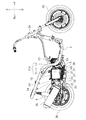
以下、図面を参照しながら、本発明の実施の形態について説明する。図1および図2に示すように、本実施形態に係る鞍乗型車両は、排ガスの酸素濃度を検出する酸素センサ50を備えたスクータ1である。
Hereinafter, embodiments of the present invention will be described with reference to the drawings. As shown in FIGS. 1 and 2, the saddle riding type vehicle according to the present embodiment is a scooter 1 including an
スクータ1は、乗員が座るシート2を備えている。以下の説明では特に断らない限り、前、後、左、右、上、下とは、乗員が乗車せずかつ荷物が搭載されておらずかつ燃料が充填されていないスクータ1が水平面上に直立した状態で停止している場合に、シート2に着座した仮想的な乗員から見た前、後、左、右、上、下をそれぞれ意味するものとする。図中のF、Re、L、R、U、Dは、それぞれ前、後、左、右、上、下を表す。
The scooter 1 includes a
図2は、後述するフロントカバー28やサイドカバー29などを取り外したときのスクータ1の側面図である。図1および図2に示すように、スクータ1は、車体フレーム3と、前輪35と、後輪36と、フートボード4と、車体フレーム3に設けられたピボット軸6とを備えている。フートボード4は車体フレーム3に支持されており、フートボード4の少なくとも一部は前輪35の後方に配置されている。また、スクータ1は、少なくとも一部が車体フレーム3のヘッドパイプ3Aの下方に位置するフロントカバー28と、車体フレーム3の車幅方向の外方に配置されたサイドカバー29と、フロントカバー28およびサイドカバー29の下方に配置されたアンダーカバー5とを備えている。アンダーカバー5の少なくとも一部は、フートボード4の下方かつ前輪35の後方に配置されている。エンジンユニット10はピボット軸6に揺動可能に支持されており、エンジンユニット10の少なくとも一部はフートボード4の下方に配置されている。
FIG. 2 is a side view of the scooter 1 when a
図2に示すように、エンジンユニット10は内燃機関11Aを備えており、内燃機関11Aは、クランクケース11と、クランクケース11に接続されたシリンダボディ12と、シリンダボディ12に接続されたシリンダヘッド13とを有している。図示は省略するが、内燃機関11Aのクランクシャフトはクランクケース11の内部に配置されている。シリンダボディ12はクランクケース11の前方に配置され、シリンダヘッド13はシリンダボディ12の前方に配置されている。シリンダヘッド13は、排ガスが排出される排気ポート14を有している。
As shown in FIG. 2, the
また、エンジンユニット10は、後輪36の左方に配置された変速機ケース7(図3参照)と、変速機ケース7の内部に配置された図示しないベルト式無段変速機(以下、CVTという)とを有している。CVTは、内燃機関11Aのクランクシャフトと後輪36とに連結されており、クランクシャフトのトルクを変速比の変更が可能なように後輪36に伝達する。後輪36は内燃機関11Aによって駆動される。図4に示すように、後輪36の右方には、クランクケース11と後輪36とを連結するリアアーム8が配置されている。後輪36は、エンジンユニット10およびリアアーム8に支持されており、エンジンユニット10およびリアアーム8と共に揺動する。車体フレーム3とリアアーム8との間には、リアクッションユニット9が設けられている(図2参照)。エンジンユニット10が上方に揺動するとリアクッションユニット9は収縮し、エンジンユニット10が下方に揺動するとリアクッションユニット9は伸張する。
The
本実施形態では、エンジンユニット10の内燃機関11Aは水冷式である。図4および図5に示すように、クランクケース11の右方にはファン16が配置され、ファン16の右方にはラジエータ15が配置されている。
In the present embodiment, the
図1に示すように、ラジエータ15の右方にはカバー60が配置されている。図6はカバー60の斜視図である。詳細は後述するが、カバー60は、ファンカバー61と、ファンカバー61の下部から後方に延びる下延長カバー62と、ファンカバー61の上部から後方に延びる上延長カバー63とを含んでいる。カバー60は単一の部品であり、ファンカバー61、下延長カバー62、および上延長カバー63は一体的に形成されている。
As shown in FIG. 1, a
ファンカバー61は、車両側面視においてファン16と重なる領域にあるカバーである。言い換えると、ファンカバー61は、ファン16の真横に位置するカバーである。図6では、ファン16の輪郭線を破線で表示している。本実施形態では、カバー60のうち、車両側面視において上記輪郭線上の部分および上記輪郭線の内側の部分がファンカバー61に対応する。ファンカバー61には、複数の開口17a,17bが形成されている。ここでは、ファンカバー61には、上下に並んだ5つの前側開口17aと、上下に並んだ3つの後側開口17bとが形成されている。ただし、上記の開口17a,17bは一例に過ぎず、ファンカバー61の開口の数、形状、および位置は何ら限定されない。
The
ファン16の羽根車(図示せず)が回転すると、ファンカバー61の開口17a,17bを通じてラジエータ15に空気が供給される。ファン16、ラジエータ15、およびカバー60は、クランクケース11に支持されているので、エンジンユニット10と一体となって揺動する。なお、エンジンユニット10の内燃機関11Aは必ずしも水冷式でなくてもよい。内燃機関11Aは空冷式であってもよく、ラジエータ15はなくてもよい。
When an impeller (not shown) of the
下延長カバー62は、それぞれ後方に延びる上縁部62aおよび下縁部62bと、上縁部62aの後端から下縁部62bの後端に延びる後縁部62cとを含んでいる。後縁部62cは、上縁部62aの後端から前方かつ下方に延びる上部62c1と、下縁部62bの後端から前方かつ上方に延びる下部62c2とを含んでおり、前方に向かって凹状に形成されている。
The
上延長カバー63は、後方かつ下方に延びる上縁部63aと、後方かつ上方に延びる下縁部63bとを含んでいる。上延長カバー63は、後方に向かって凸状に形成されている。ただし、上延長カバー63の上記形状は一例に過ぎず、特に限定される訳ではない。また、上延長カバー63は必ずしも必要ではなく、省略することが可能である。
The
図1に示すように、スクータ1は、排気管24とサイレンサ25とを備えている。排気管24は、第1排気管21と、触媒20が収容された触媒ケース23と、第2排気管22とを含んでいる。サイレンサ25の側方には、サイレンサカバー26が配置されている。これら第1排気管21、触媒ケース23、第2排気管22、サイレンサ25、およびサイレンサカバー26は、エンジンユニット10と一体となって揺動するように構成されている。
As shown in FIG. 1, the scooter 1 includes an
図3に示すように、第1排気管21の上流端部21aは、シリンダヘッド13の排気ポート14に接続されている。第1排気管21と触媒ケース23とは、第1管継手31によって接続されている。触媒ケース23と第2排気管22とは、第2管継手32によって接続されている。第2排気管22とサイレンサ25とは、第3管継手33によって接続されている。
As shown in FIG. 3, the upstream end 21 a of the
第1排気管21は金属製のパイプである。第1排気管21は、エンジンユニット10の下方に配置されている。図3に示すように車両底面視において、第1排気管21はエンジンユニット10と重なるように配置されている。
The
第2排気管22も金属製のパイプである。第2排気管22は、車両底面視において、後方かつ車幅方向の外方に延びている。図1に示すように車両側面視において、第2排気管22は後方かつ上方に延びている。
The
触媒ケース23は、金属製の円筒によって形成されている。ただし、触媒ケース23の形状は特に限定されない。触媒ケース23の内部には、触媒20が配置されている。触媒20は排気管24の内部に配置されており、排気管24を流れる排ガスを浄化する。触媒ケース23は後輪36よりも前方に配置されており、触媒20は後輪36よりも前方に配置されている。触媒ケース23の内径は、第1排気管21および第2排気管22のいずれの内径よりも大きい。また、触媒ケース23の外径は、第1排気管21および第2排気管22のいずれの外径よりも大きい。図3に示すように車両底面視において、触媒ケース23は後方かつ車幅方向の外方に延びている。図1に示すように車両側面視において、触媒ケース23は後方に延びている。ただし、触媒ケース23の設置姿勢は特に限定されない。
The
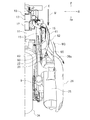
図7に示すように、第1排気管21には第1酸素センサ40が取り付けられている。第1酸素センサ40は触媒20の上流側に配置されており、触媒20によって浄化される前の排ガスの酸素濃度を検出する。第1酸素センサ40により検出される排ガスの酸素濃度に基づいて、内燃機関11Aから排出される排ガスの空燃比を検出することができる。そのため、第1酸素センサ40の検出結果に基づいて、所定の燃焼状態が得られるよう内燃機関11Aを制御することができる。
As shown in FIG. 7, a
図3に示すように、第1酸素センサ40は、第1排気管21の中間位置(図3に破線で示す位置)21mよりも触媒20に近い方の部分に取り付けられている。なお、第1排気管21の中間位置とは、第1排気管21の中心線に沿った方向における上流端部21aと下流端部21bとの中間の位置のことである。第1酸素センサ40は、エンジンユニット10のシリンダボディ12よりも後方に配置されている。また、第1酸素センサ40は、エンジンユニット10を揺動可能に支持するピボット軸6よりも後方に配置されている。
As shown in FIG. 3, the
図7に示すように、第1排気管21には、第1酸素センサ40を取り付けるための取付部43が設けられている。取付部43は円筒状に形成されており、第1排気管21に溶接されている。
As shown in FIG. 7, the
図1に示すように車両側面視において、第1酸素センサ40はサイドカバー29によって覆われておらず、露出している。第1酸素センサ40は、スクータ1を右方から見たときに視認されるように配置されている。図3に示すように車両底面視において、第1酸素センサ40はクランクケース11と重なっているが、アンダーカバー5とは重なっていない。車両底面視において、第1酸素センサ40の少なくとも一部は、前輪35の左端35Lよりも右方かつ右端35Rよりも左方に配置されている。第1酸素センサ40は車両の中央付近に配置されている。
As shown in FIG. 1, the
図7に示すように、第2排気管22には第2酸素センサ50が取り付けられている。第2酸素センサ50は触媒20の下流側に配置されており、触媒20によって浄化された後の排ガスの酸素濃度を検出する。触媒20が劣化している場合、排ガスは適切に浄化されない。そのため、第2酸素センサ50の検出結果に基づいて、触媒20が劣化しているか否かを検出することができる。第1酸素センサ40の検出結果と第2酸素センサ50の検出結果とを比較することにより、触媒20の劣化を検出するようにしてもよい。
As shown in FIG. 7, a
図7に示すように、第2排気管22には、第2酸素センサ50を取り付けるための取付部54が設けられている。取付部54は円筒状に形成されており、第2排気管22に溶接されている。
As shown in FIG. 7, the
図2に示すように、第2酸素センサ50はエンジンユニット10の内燃機関11Aよりも後方に配置されている。図7に示すように、第2酸素センサ50の少なくとも一部は、車両側面視において後輪36と重なる位置に配置されている。
As shown in FIG. 2, the
図9に示すように、第2酸素センサ50は、第2排気管22の内部に位置するセンサ素子51と、第2排気管22の外部に位置する筒状のケース52と、センサ素子51を加熱するヒータ53とを有している。センサ素子51は、例えばジルコニア等の素材を含んでいる。ヒータ53は第2酸素センサ50に内蔵されている。
As shown in FIG. 9, the
図9に示すように、第2酸素センサ50の中心線50Cを含みかつ第2排気管22の中心線22Cと垂直な断面において、ケース52の少なくとも一部は、第2排気管22の中心線22Cよりも車幅方向の内方かつ上方に配置されている。ただし、ここで説明する第2酸素センサ50の設置姿勢は一例であり、特に限定される訳ではない。なお、車幅方向の内方とは車両中心線CLに近づく方を言い、車幅方向の外方とは車両中心線CL(図3参照)から遠ざかる方を言う。
As shown in FIG. 9, in a cross section including the
図1に示すように、第1酸素センサ40には第1電線45が接続されている。第1電線45の一部は車両側面視において露出している。第1電線45の一部は、右方から見て視認されるようになっている。そのため、第1酸素センサ40のメンテナンス等を行うときに右方から第1電線45を容易に取り扱うことができ、第1酸素センサ40のメンテナンスが容易である。第1電線45は、第1酸素センサ40から上方に向かって延びた後、前方に向かって延びている。第1電線45はエンジンユニット10の下方を通っていない。第1電線45は、図示しないECU(Electronic Control Unit)に接続されている。
As shown in FIG. 1, a first
図9に示すように、第2酸素センサ50は電線接続部55を有し、電線接続部55には第2電線46が接続されている。電線接続部55は、センサ素子51よりも車両上下方向の上方かつ車幅方向の内方に配置されている。図7に示すように、第2電線46は、第2酸素センサ50から上方に向かって延びた後、前方に向かって延びている。第2電線46はファン16の上方を通っている。第2電線46の一部46aはファン16の上方に配置されている。第2電線46は、エンジンユニット10の下方を通っていない。第2電線46は前記ECUに接続されている。
As shown in FIG. 9, the
図8Aおよび図8Bに示すように、車両正面視において、第1酸素センサ40および第2酸素センサ50とアンダーカバー5とは重なっている。第1酸素センサ40および第2酸素センサ50は、スクータ1を前方から見たときに視認されないように配置されている。
As shown in FIGS. 8A and 8B, the
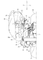
図7に示すように、車両側面視において、下延長カバー62の一部は、第2酸素センサ50の少なくとも一部と重なっている。本実施形態では、下延長カバー62の上記一部は、センサカバー65を構成している。センサカバー65は、ファンカバー61の開口17a,17bよりも後方に配置されている。図4に示すように、センサカバー65は、第2酸素センサ50よりも車幅方向の外方に位置している。下延長カバー62は車幅方向の外方かつ車両前後方向の後方に延びており、センサカバー65も車幅方向の外方かつ車両前後方向の後方に延びている。
As shown in FIG. 7, a part of the
サイレンサカバー26は、サイレンサ25の車幅方向の外方に配置されている。サイレンサカバー26の前部26aは、第2酸素センサ50よりも車幅方向の外方に位置している。また、サイレンサカバー26の前部26aは、車幅方向の外方かつ車両前後方向の後方に延びており、本実施形態では湾曲している。
The
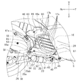
本実施形態では図4に示すように車両平面視において、下延長カバー62の後端62dとサイレンサカバー26の前部26aの前端26aaとは、車両前後方向に関して同じ位置にある。車両平面視において、下延長カバー62の後端62dを通りかつ車幅方向に延びる直線をL1、サイレンサカバー26の前部26aの前端26aaを通りかつ車幅方向に延びる直線L2とすると、直線L1と直線L2とは一致する。下延長カバー62の後端62dとサイレンサカバー26の前部26aの前端26aaとの間の車両前後方向の距離をΔAとすると、本実施形態ではΔA=0である。図7において、符号61aはファンカバー61の後端を表している。図4において、符号L3は、車両平面視においてファンカバー61の後端61aを通りかつ車幅方向に延びる直線を表している。符号L4は、車両平面視においてサイレンサ25の前端25aを通りかつ車幅方向に延びる直線を表している。車両平面視において、ファンカバー61の後端61aとサイレンサ25の前端25aとの間の車両前後方向の距離をΔBとする。すると、ΔA<ΔBである。
In the present embodiment, as shown in FIG. 4, the
図4において、符号L5は、車両平面視においてサイレンサカバー26の前部26aの車幅方向の内端26ae通りかつ車両前後方向に延びる直線を表す。符号L6は、車両平面視において下延長カバー62の車幅方向の外端62eを通りかつ車両前後方向に延びる直線を表す。ここで、直線L5は直線L6よりも車幅方向の内方に位置している。すなわち、車両平面視において、サイレンサカバー26の前部26aの車幅方向の内端26aeは、下延長カバー62の車幅方向の外端62eよりも車幅方向の内方に位置している。
In FIG. 4, a symbol L <b> 5 represents a straight line extending in the vehicle front-rear direction through the
なお、本実施形態では前述の通り、車両前後方向に関して、サイレンサカバー26の前部26aの前端26aaは下延長カバー62の後端62dと同じ位置にあるが、それらの位置関係は特に限定されない。車両前後方向に関して、サイレンサカバー26の前部26aの前端26aaは、下延長カバー62の後端62dよりも前方に位置していてもよく、ΔA>0であってもよい。ΔA>0の場合であっても、ΔA<ΔBであることが好ましい。
In the present embodiment, as described above, the front end 26aa of the
図7に示すように、車両側面視において、センサカバー65とサイレンサカバー26の前部26aとは、互いに適合した形状に形成されている。ここでは、車両側面視において、センサカバー65には前方に向けて凹んだ凹部65aが形成され、サイレンサカバー26の前部26aには、凹部65aに向けて前方に突出する凸部26abが形成されている。
As shown in FIG. 7, the
車両側面視において、センサカバー65とサイレンサカバー26の前部26aとの間には、車両前後方向に間隔が設けられているが、それらの間隔は比較的小さい。間隔は上下の位置によって異なるが、それらの間隔のうち最小の間隔G1は、第2酸素センサ50のケース52の軸線方向の寸法F1(図9参照)よりも小さい。ただし、これは一例であって、最小間隔G1は特に限定されない。
When viewed from the side of the vehicle, an interval is provided between the
センサカバー65は、車両側面視において第2酸素センサ50の電線接続部55と重なっている。第2電線46の一部は、車両側面視においてセンサカバー65と重なっている。第2電線46の他の一部は、カバー60の上延長カバー63の車幅方向の内方に位置し、かつ、車両側面視において上延長カバー63と重なっている。上延長カバー63の一部は、電線カバー66を構成している。第2電線46の一部46aは、ファン16よりも上方かつファンカバー61よりも車幅方向の内方に配置されており、前方に向かって延びている。
The
以上がスクータ1の構成である。次に、第2酸素センサ50に対する走行風の影響について説明する。
The above is the configuration of the scooter 1. Next, the influence of traveling wind on the
スクータ1が走行すると、図10に示すように、前方から後方に向かって風(すなわち走行風)Wが流れる。ファンカバー61は、開口17a,17b(図6参照)に空気を導入しやすいように、走行風Wが当たる位置に配置されている。本実施形態では、第2酸素センサ50はファンカバー61の近傍に配置されている。ここで図11に示すように、センサカバー65がないと仮定した場合、ファンカバー61に沿って流れた走行風W1は第2酸素センサ50に向かって流れ、第2酸素センサ50を冷却してしまう。この場合、第2酸素センサ50はヒータ53(図9参照)を内蔵しているが、センサ素子51の温度は低下し、検出精度が低下するおそれがある。
When the scooter 1 travels, wind (that is, travel wind) W flows from the front to the rear as shown in FIG. The
しかし、本実施形態によれば、第2酸素センサ50の車幅方向の外方には、ファンカバー61と一体的に形成されたセンサカバー65が配置されている。そのため、第2酸素センサ50に走行風W1が直接当たってしまうことを防止することができる。一方、図12に示すように、センサカバー65の後端65dとサイレンサカバー26の前部26aの前端26aaとの間の車両前後方向の距離ΔAが大きい場合、センサカバー65の後方に負圧が生じることにより、センサカバー65の表面に沿って流れた走行風W2がその負圧によってセンサカバー65の内側に流入し、第2酸素センサ50の周囲に流れてしまうという問題が生じる。
However, according to the present embodiment, the
しかし、本実施形態によれば、センサカバー65の後端65dとサイレンサカバー26の前部26aの前端26aaとの間の車両前後方向の距離ΔAは小さく、零である(図4参照)。加えて、センサカバー65およびサイレンサカバー26の前部26aは、共に車幅方向の外方かつ車両前後方向の後方に延びている。そのため、図10に示すように、センサカバー65の表面に沿って流れた走行風W3は、そのままサイレンサカバー26の前部26aの表面に沿って後方に流れやすい。このように本実施形態によれば、センサカバー65およびサイレンサカバー26が協働することにより、走行風が第2酸素センサ50に向かって流れることを抑制することができる。
However, according to the present embodiment, the distance ΔA in the vehicle front-rear direction between the
以上のように、本実施形態に係るスクータ1によれば、走行風が第2酸素センサ50に向かって流れることが抑制することができるので、第2酸素センサ50が走行風によって冷却されてしまうことを抑制することができる。したがって、センサ素子51の温度低下を抑えることができ、第2酸素センサ50の検出精度を良好に保つことができる。
As described above, according to the scooter 1 according to the present embodiment, it is possible to suppress the traveling wind from flowing toward the
センサカバー65およびサイレンサカバー26の前部26aの位置関係は特に限定されないが、本実施形態では、図4に示すように車両平面視において、サイレンサカバー26の前部26aの車幅方向の内端26aeは、センサカバー65の車幅方向の外端62eよりも車幅方向の内方に位置している。また、本実施形態によれば、車両平面視において、サイレンサカバー26の前部26aの前端26aaは、センサカバー65の車幅方向の外端62eよりも車幅方向の内方に位置している。本実施形態によれば、センサカバー65およびサイレンサカバー26の前部26aが上記のような位置関係にあるので、走行風が負圧により第2酸素センサ50の周囲に流れてしまうことを更に抑制することができる。
Although the positional relationship between the
本実施形態では、車両前後方向に関して、サイレンサカバー26の前部26aの前端26aaは、センサカバー65の後端62dと同じ位置にある。ΔA=0である。このことにより、走行風が負圧により第2酸素センサ50の周囲に流れてしまうことを更に抑制することができる。
In the present embodiment, the front end 26aa of the
ところで、第2酸素センサ50がエンジンユニット10の内燃機関11Aの排気ポート14の近くに配置されていれば、第2酸素センサ50は、排気ポート14から排出された直後の高温の排ガスによって加熱される。その場合、第2酸素センサ50のセンサ素子51の温度は低下しにくい。しかし、本実施形態によれば、図2に示すように、第2酸素センサ50はエンジンユニット10の内燃機関11Aよりも後方に配置されている。また、第2酸素センサ50は、少なくともその一部が車両側面視において後輪36と重なるほど後方に配置されている。第2酸素センサ50は、触媒20よりも排ガスの流通方向の下流側に配置されている。本実施形態によれば、第2酸素センサ50は排気ポート14から遠い位置に配置されており、また、ファンカバー61の近傍に位置するので、センサ素子51の温度低下を抑えることにより第2酸素センサ50の検出精度を良好に保つという前述の効果が特に顕著に発揮される。
By the way, if the
また、本実施形態によれば、図7に示すように、センサカバー65はファンカバー61の開口17a,17bよりも後方に配置されている。そのため、走行風の一部を開口17a,17bを通じてファン16に供給することができ、走行風の他の一部をセンサカバー65により、第2酸素センサ50に当たらないようにしつつ後方に円滑に導くことができる。
Further, according to the present embodiment, as shown in FIG. 7, the
また、本実施形態によれば、車両側面視において、センサカバー65とサイレンサカバー26の前部26aとの間の車両前後方向の最小間隔G1は、第2酸素センサ50のケース52の軸線方向の寸法F1(図9参照)よりも小さい。このように、センサカバー65とサイレンサカバー26の前部26aとの間の車両前後方向の最小間隔G1が小さいので、走行風が負圧により第2酸素センサ50の周囲に流れてしまうことを更に抑制することができる。
Further, according to the present embodiment, in the vehicle side view, the minimum distance G1 in the vehicle longitudinal direction between the
また、本実施形態によれば、車両側面視において、センサカバー65には前方に向けて凹んだ凹部65aが形成され、サイレンサカバー26の前部26aには、凹部65aに向けて前方に突出する凸部26abが形成されている。センサカバー65とサイレンサカバー26の前部26aとは、車両側面視において互いに適合した形状に形成されている。よって、センサカバー65の表面に沿って流れた走行風がセンサカバー65の内側に流入することを効果的に抑制することができ、第2酸素センサ50が走行風により冷却されることを効果的に抑制することができる。
Further, according to the present embodiment, the
本実施形態によれば、センサカバー65は、車両側面視において第2酸素センサ50の電線接続部55と重なっている。そのため、センサカバー65により、第2酸素センサ50の電線接続部55を保護することができる。
According to the present embodiment, the
また、本実施形態によれば、カバー60は、第2電線46の少なくとも一部の車幅方向の外方に位置し、かつ、車両側面視において第2電線46の少なくとも一部と重なる電線カバー66を有している。そのため、電線カバー66により、第2電線46の少なくとも一部を保護することができる。
Further, according to the present embodiment, the
また、本実施形態によれば図9に示すように、第2酸素センサ50の電線接続部55は、センサ素子51よりも車両上下方向の上方かつ車幅方向の内方に配置されている。このように、電線接続部55はセンサ素子51よりも上方に配置されているので、第2酸素センサ50のメンテナンスが容易である。また、電線接続部55はセンサ素子51よりも車幅方向の内方に配置されているので、電線接続部55が車幅方向の外方に出っ張ることを避けることができる。
Further, according to the present embodiment, as shown in FIG. 9, the electric
また、本実施形態によれば図7に示すように、第2電線46は、ファン16よりも上方かつファンカバー61よりも車幅方向の内方に配置され、前方に向かって延びる部分46aを有している。そのため、第2電線46の配策が容易となる。
Further, according to the present embodiment, as shown in FIG. 7, the second
以上、本発明の実施の一形態について説明したが、本発明が前記実施形態に限定されないことは勿論である。 As mentioned above, although one Embodiment of this invention was described, of course, this invention is not limited to the said embodiment.
前記実施形態では、エンジンユニット10の変速機ケース7は車両中心線CLの左方に配置され、第2酸素センサ50、カバー60、およびサイレンサカバー26は車両中心線CLの右方に配置されているが、変速機ケース7が車両中心線CLの右方に配置され、第2酸素センサ50、カバー60、およびサイレンサカバー26が車両中心線CLの左方に配置されていてもよい。
In the embodiment, the
前記実施形態では、第2酸素センサ50の少なくとも一部が車両側面視において後輪36と重なる位置に配置されているが、第2酸素センサ50の全体が車両側面視において後輪36と重なっていなくてもよい。
In the embodiment, at least a part of the
前記実施形態では、第2酸素センサ50は触媒20の下流側に配置されているが、第2酸素センサ50の位置は特に限定されない。第2酸素センサ50は、触媒20の上流側に配置されていてもよい。
In the embodiment, the
前記実施形態では、センサカバー65はファンカバー61の開口17a,17bよりも後方に配置されているが、センサカバー65の一部または全部は、ファンカバー61の開口17a,17bよりも後方に配置されていなくてもよい。
In the embodiment, the
前記実施形態では、センサカバー65に凹部65aが形成され、サイレンサカバー26の前部26aに凸部26abが形成され、センサカバー65とサイレンサカバー26の前部26aとは、車両側面視において互いに適合する形状を有している。しかし、センサカバー65とサイレンサカバー26の前部26aとは、車両側面視において互いに適合しない形状を有していてもよい。
In the embodiment, the
前記実施形態では、センサカバー65は車両側面視において第2酸素センサ50の電線接続部55と重なっているが、特に限定されない。センサカバー65は、車両側面視において第2酸素センサ50の一部または全部と重なっていなくてもよい。
In the embodiment, the
前記実施形態では、カバー60は、車両側面視において第2電線46の少なくとも一部と重なる電線カバー66を有している。しかし、カバー60はそのような電線カバー66を有していなくてもよい。
In the embodiment, the
第2酸素センサ50の設置姿勢は特に限定されない。電線接続部55をセンサ素子51よりも車両上下方向の下方に配置することも可能である。また、電線接続部55をセンサ素子51よりも車幅方向の外方に配置することも可能である。
The installation posture of the
前記実施形態では、エンジンユニット10の内燃機関11Aは水冷式であり、スクータ1はラジエータ15を備えている。しかし、内燃機関11Aは空冷式であってもよい。スクータ1はラジエータ15を備えていなくてもよい。ファン16は、内燃機関11Aに空気を供給するように構成されていてもよい。
In the above-described embodiment, the
鞍乗型車両とは、乗員が跨がって乗車する車両のことである。鞍乗型車両はスクータ1に限定されない。鞍乗型車両は、他の形式の自動二輪車であってもよい。また、鞍乗型車両は、自動二輪車以外の車両、例えば、自動三輪車、ATV(All Terrain Vehicle)であってもよい。 A straddle-type vehicle is a vehicle on which an occupant rides. The straddle-type vehicle is not limited to the scooter 1. The saddle riding type vehicle may be another type of motorcycle. The straddle-type vehicle may be a vehicle other than a motorcycle, for example, an automatic tricycle or an ATV (All Terrain Vehicle).
ここに用いられた用語及び表現は、説明のために用いられたものであって限定的に解釈するために用いられたものではない。ここに示されかつ述べられた特徴事項の如何なる均等物をも排除するものではなく、本発明のクレームされた範囲内における各種変形をも許容するものであると認識されなければならない。本発明は、多くの異なった形態で具現化され得るものである。この開示は本発明の原理の実施形態を提供するものと見なされるべきである。それらの実施形態は、本発明をここに記載しかつ/又は図示した好ましい実施形態に限定することを意図するものではないという了解のもとで、実施形態がここに記載されている。ここに記載した実施形態に限定されるものではない。本発明は、この開示に基づいて当業者によって認識され得る、均等な要素、修正、削除、組み合わせ、改良及び/又は変更を含むあらゆる実施形態をも包含する。クレームの限定事項はそのクレームで用いられた用語に基づいて広く解釈されるべきであり、本明細書あるいは本願のプロセキューション中に記載された実施形態に限定されるべきではない。 The terms and expressions used herein are used for explanation and are not used for limited interpretation. It should be recognized that any equivalents of the features shown and described herein are not excluded and that various modifications within the claimed scope of the invention are permitted. The present invention can be embodied in many different forms. This disclosure should be regarded as providing embodiments of the principles of the invention. The embodiments are described herein with the understanding that the embodiments are not intended to limit the invention to the preferred embodiments described and / or illustrated herein. It is not limited to the embodiment described here. The present invention encompasses any embodiment that includes equivalent elements, modifications, deletions, combinations, improvements and / or changes that may be recognized by those skilled in the art based on this disclosure. Claim limitations should be construed broadly based on the terms used in the claims and should not be limited to the embodiments described herein or in the process of this application.
1…スクータ、10…エンジンユニット、15…ラジエータ、16…ファン、17a,17b…開口、20…触媒、24…排気管、25…サイレンサ、26…サイレンサカバー、26a…サイレンサカバーの前部、35…前輪、36…後輪、46…第2電線(電線)、46a…電線部分、50…第2酸素センサ(酸素センサ)、51…センサ素子、52…ケース、53…ヒータ、55…電線接続部、60…カバー、61…ファンカバー、65…センサカバー、66…電線カバー DESCRIPTION OF SYMBOLS 1 ... Scooter, 10 ... Engine unit, 15 ... Radiator, 16 ... Fan, 17a, 17b ... Opening, 20 ... Catalyst, 24 ... Exhaust pipe, 25 ... Silencer, 26 ... Silencer cover, 26a ... Front part of silencer cover, 35 ... front wheel, 36 ... rear wheel, 46 ... second electric wire (electric wire), 46a ... electric wire part, 50 ... second oxygen sensor (oxygen sensor), 51 ... sensor element, 52 ... case, 53 ... heater, 55 ... electric wire connection Part, 60 ... cover, 61 ... fan cover, 65 ... sensor cover, 66 ... electric wire cover
Claims (16)
前記内燃機関に接続された排気管と、
前記排気管の後方に配置され、前記排気管に接続されたサイレンサと、
前記内燃機関の車幅方向の外方に配置されたファンと、
前記ファンの車幅方向の外方に配置され、開口が形成されたファンカバーと、
前記サイレンサの車幅方向の外方に配置されたサイレンサカバーと、
前記排気管の内部に配置されたセンサ素子と前記センサ素子を加熱するヒータとを有し、前記排気管に取り付けられた酸素センサと、
前記ファンカバーと一体的に形成され、前記酸素センサよりも車幅方向の外方に位置し、車両側面視において前記酸素センサの少なくとも一部と重なり、車幅方向の外方かつ車両前後方向の後方に延びるセンサカバーと、を備え、
前記サイレンサカバーは、前記酸素センサよりも車幅方向の外方に位置し、車幅方向の外方かつ車両前後方向の後方に延びる前部を有し、
車両平面視において、前記センサカバーの後端と前記サイレンサカバーの前記前部の前端との間の車両前後方向の距離は、前記ファンカバーの後端と前記サイレンサの前端との間の車両前後方向の距離よりも短い、鞍乗型車両。 An internal combustion engine;
An exhaust pipe connected to the internal combustion engine;
A silencer disposed behind the exhaust pipe and connected to the exhaust pipe;
A fan disposed outside in the vehicle width direction of the internal combustion engine;
A fan cover disposed outside the vehicle in the vehicle width direction and having an opening formed therein;
A silencer cover arranged outside the silencer in the vehicle width direction;
A sensor element disposed inside the exhaust pipe and a heater for heating the sensor element; an oxygen sensor attached to the exhaust pipe;
The fan cover is formed integrally with the oxygen sensor and is located outward of the oxygen sensor in the vehicle width direction, and overlaps at least a part of the oxygen sensor in a side view of the vehicle. A sensor cover extending rearward,
The silencer cover is located on the outer side in the vehicle width direction than the oxygen sensor, and has a front portion extending outward in the vehicle width direction and rearward in the vehicle front-rear direction,
In the vehicle plan view, the distance in the vehicle longitudinal direction between the rear end of the sensor cover and the front end of the front portion of the silencer cover is the vehicle longitudinal direction between the rear end of the fan cover and the front end of the silencer. Saddle-type vehicle that is shorter than the distance.
前記酸素センサの少なくとも一部は、車両側面視において前記後輪と重なる位置に配置されている、請求項1〜5のいずれか一つに記載の鞍乗型車両。 A rear wheel driven by the internal combustion engine,
The straddle-type vehicle according to any one of claims 1 to 5, wherein at least a part of the oxygen sensor is disposed at a position overlapping the rear wheel in a side view of the vehicle.
前記酸素センサは、前記触媒よりも排ガスの流通方向の下流側に配置されている、請求項1〜6のいずれか一つに記載の鞍乗型車両。 A catalyst for purifying exhaust gas flowing through the exhaust pipe;
The straddle-type vehicle according to any one of claims 1 to 6, wherein the oxygen sensor is disposed downstream of the catalyst in the flow direction of exhaust gas.
車両側面視において、前記センサカバーと前記サイレンサカバーの前記前部との間の車両前後方向の最小間隔は、前記酸素センサの前記ケースの軸線方向の寸法よりも小さい、請求項1〜8のいずれか一つに記載の鞍乗型車両。 The oxygen sensor has a cylindrical case located outside the exhaust pipe,
The vehicle front-rear direction minimum distance between the sensor cover and the front part of the silencer cover in a vehicle side view is smaller than the dimension of the oxygen sensor in the axial direction of the case. A straddle-type vehicle according to any one of the above.
前記電線接続部に接続された電線を備えている、請求項1〜10のいずれか一つに記載の鞍乗型車両。 The oxygen sensor has a wire connection part,
The straddle-type vehicle according to any one of claims 1 to 10, further comprising an electric wire connected to the electric wire connecting portion.
前記電線接続部は、前記センサ素子よりも車両上下方向の上方かつ車幅方向の内方に配置されている、請求項11〜13のいずれか一つに記載の鞍乗型車両。 The oxygen sensor has a sensor element located inside the exhaust pipe,
The straddle-type vehicle according to any one of claims 11 to 13, wherein the electric wire connection portion is disposed above the sensor element in an upper and lower direction of the vehicle and inward in the vehicle width direction.
Priority Applications (4)
| Application Number | Priority Date | Filing Date | Title |
|---|---|---|---|
| JP2018083218A JP2019190355A (en) | 2018-04-24 | 2018-04-24 | Saddle riding-type vehicle |
| TW108110470A TWI727290B (en) | 2018-04-24 | 2019-03-26 | Straddled vehicle |
| EP19168292.1A EP3561246B1 (en) | 2018-04-24 | 2019-04-10 | Straddled vehicle |
| PH12019050057A PH12019050057A1 (en) | 2018-04-24 | 2019-04-16 | Straddled vehicle |
Applications Claiming Priority (1)
| Application Number | Priority Date | Filing Date | Title |
|---|---|---|---|
| JP2018083218A JP2019190355A (en) | 2018-04-24 | 2018-04-24 | Saddle riding-type vehicle |
Publications (1)
| Publication Number | Publication Date |
|---|---|
| JP2019190355A true JP2019190355A (en) | 2019-10-31 |
Family
ID=66104996
Family Applications (1)
| Application Number | Title | Priority Date | Filing Date |
|---|---|---|---|
| JP2018083218A Pending JP2019190355A (en) | 2018-04-24 | 2018-04-24 | Saddle riding-type vehicle |
Country Status (4)
| Country | Link |
|---|---|
| EP (1) | EP3561246B1 (en) |
| JP (1) | JP2019190355A (en) |
| PH (1) | PH12019050057A1 (en) |
| TW (1) | TWI727290B (en) |
Families Citing this family (1)
| Publication number | Priority date | Publication date | Assignee | Title |
|---|---|---|---|---|
| TWI758076B (en) * | 2021-01-20 | 2022-03-11 | 光陽工業股份有限公司 | Cooling mechanism of continuously variable transmission system |
Family Cites Families (8)
| Publication number | Priority date | Publication date | Assignee | Title |
|---|---|---|---|---|
| JP4900293B2 (en) | 2008-03-19 | 2012-03-21 | スズキ株式会社 | Exhaust gas sensor device for motorcycles |
| JP5911336B2 (en) * | 2012-02-27 | 2016-04-27 | 本田技研工業株式会社 | Small vehicle |
| JP2017150312A (en) * | 2014-07-04 | 2017-08-31 | ヤマハ発動機株式会社 | Engine unit and vehicle |
| EP3165742B1 (en) * | 2014-07-04 | 2021-05-26 | Yamaha Hatsudoki Kabushiki Kaisha | Vehicle and single-cylinder four-stroke engine unit |
| WO2016002955A1 (en) * | 2014-07-04 | 2016-01-07 | ヤマハ発動機株式会社 | Vehicle and single-cylinder four-stroke engine unit |
| JP2017150309A (en) * | 2014-07-04 | 2017-08-31 | ヤマハ発動機株式会社 | Engine unit and ride type vehicle |
| WO2016002956A1 (en) * | 2014-07-04 | 2016-01-07 | ヤマハ発動機株式会社 | Vehicle and v-type multi-cylinder four-stroke engine unit |
| ES2946345T3 (en) * | 2014-12-19 | 2023-07-17 | Yamaha Motor Co Ltd | Straddle vehicle |
-
2018
- 2018-04-24 JP JP2018083218A patent/JP2019190355A/en active Pending
-
2019
- 2019-03-26 TW TW108110470A patent/TWI727290B/en active
- 2019-04-10 EP EP19168292.1A patent/EP3561246B1/en active Active
- 2019-04-16 PH PH12019050057A patent/PH12019050057A1/en unknown
Also Published As
| Publication number | Publication date |
|---|---|
| PH12019050057A1 (en) | 2019-12-11 |
| TWI727290B (en) | 2021-05-11 |
| EP3561246B1 (en) | 2020-12-02 |
| EP3561246A1 (en) | 2019-10-30 |
| TW201945218A (en) | 2019-12-01 |
Similar Documents
| Publication | Publication Date | Title |
|---|---|---|
| EP3235714B1 (en) | Saddle-ride vehicle | |
| EP2295762B1 (en) | Engine and saddle-riding type vehicle including the same | |
| US8783024B2 (en) | Exhaust chamber in motorcycle exhaust system | |
| JP2007145130A (en) | Motorcycle | |
| JP2006307693A (en) | Exhaust device for motorcycle | |
| JP6364123B2 (en) | Motorcycle exhaust system | |
| JP2007076423A (en) | Cowling of motorcycle | |
| US7793748B2 (en) | Vehicle cowl with opening for horn | |
| JP2007085235A (en) | Exhaust muffler of motorcycle | |
| EP3450293B1 (en) | Saddle riding vehicle | |
| JP2019190355A (en) | Saddle riding-type vehicle | |
| US10920639B2 (en) | Saddle riding vehicle | |
| JP2019015277A (en) | Exhaust gas sensor arrangement structure and motor cycle | |
| JP2014238094A (en) | Exhaust gas sensor mounting structure of motorcycle | |
| JPWO2018029822A1 (en) | Saddle riding | |
| JP6378611B2 (en) | Engine exhaust system | |
| EP3561252B1 (en) | Scooter | |
| JP5585213B2 (en) | Exhaust gas passage structure of internal combustion engine | |
| JP6446420B2 (en) | Saddle-type vehicle with water-cooled engine | |
| JP2017150310A (en) | Engine unit and ride type vehicle | |
| EP3561245B1 (en) | Straddled vehicle | |
| JP5018164B2 (en) | Motorcycle | |
| JP7275775B2 (en) | motorcycle | |
| JP2006007809A (en) | Air cooling device for vehicle | |
| JP2019039406A (en) | Saddle-riding type vehicle |