JP5868614B2 - Soldering device - Google Patents
Soldering device Download PDFInfo
- Publication number
- JP5868614B2 JP5868614B2 JP2011120220A JP2011120220A JP5868614B2 JP 5868614 B2 JP5868614 B2 JP 5868614B2 JP 2011120220 A JP2011120220 A JP 2011120220A JP 2011120220 A JP2011120220 A JP 2011120220A JP 5868614 B2 JP5868614 B2 JP 5868614B2
- Authority
- JP
- Japan
- Prior art keywords
- processing chamber
- soldering
- blower
- inert gas
- chamber
- Prior art date
- Legal status (The legal status is an assumption and is not a legal conclusion. Google has not performed a legal analysis and makes no representation as to the accuracy of the status listed.)
- Active
Links
- 238000005476 soldering Methods 0.000 title claims description 60
- 238000001816 cooling Methods 0.000 claims description 60
- 239000011261 inert gas Substances 0.000 claims description 46
- 239000007789 gas Substances 0.000 claims description 35
- 238000007664 blowing Methods 0.000 claims description 9
- 238000010438 heat treatment Methods 0.000 claims description 9
- 238000002844 melting Methods 0.000 claims description 9
- 230000008018 melting Effects 0.000 claims description 9
- 239000000155 melt Substances 0.000 claims description 3
- 239000000758 substrate Substances 0.000 description 66
- IJGRMHOSHXDMSA-UHFFFAOYSA-N Atomic nitrogen Chemical compound N#N IJGRMHOSHXDMSA-UHFFFAOYSA-N 0.000 description 10
- 229910001873 dinitrogen Inorganic materials 0.000 description 10
- 238000000034 method Methods 0.000 description 5
- 229910000679 solder Inorganic materials 0.000 description 5
- 239000000725 suspension Substances 0.000 description 3
- XLYOFNOQVPJJNP-UHFFFAOYSA-N water Substances O XLYOFNOQVPJJNP-UHFFFAOYSA-N 0.000 description 2
- 230000015572 biosynthetic process Effects 0.000 description 1
- 239000006071 cream Substances 0.000 description 1
- 230000007547 defect Effects 0.000 description 1
- 230000002950 deficient Effects 0.000 description 1
- 238000007872 degassing Methods 0.000 description 1
- 238000003780 insertion Methods 0.000 description 1
- 230000037431 insertion Effects 0.000 description 1
- 230000003647 oxidation Effects 0.000 description 1
- 238000007254 oxidation reaction Methods 0.000 description 1
- 239000007921 spray Substances 0.000 description 1
Images
Classifications
-
- B—PERFORMING OPERATIONS; TRANSPORTING
- B23—MACHINE TOOLS; METAL-WORKING NOT OTHERWISE PROVIDED FOR
- B23K—SOLDERING OR UNSOLDERING; WELDING; CLADDING OR PLATING BY SOLDERING OR WELDING; CUTTING BY APPLYING HEAT LOCALLY, e.g. FLAME CUTTING; WORKING BY LASER BEAM
- B23K1/00—Soldering, e.g. brazing, or unsoldering
- B23K1/0008—Soldering, e.g. brazing, or unsoldering specially adapted for particular articles or work
- B23K1/0016—Brazing of electronic components
-
- B—PERFORMING OPERATIONS; TRANSPORTING
- B23—MACHINE TOOLS; METAL-WORKING NOT OTHERWISE PROVIDED FOR
- B23K—SOLDERING OR UNSOLDERING; WELDING; CLADDING OR PLATING BY SOLDERING OR WELDING; CUTTING BY APPLYING HEAT LOCALLY, e.g. FLAME CUTTING; WORKING BY LASER BEAM
- B23K1/00—Soldering, e.g. brazing, or unsoldering
- B23K1/008—Soldering within a furnace
-
- B—PERFORMING OPERATIONS; TRANSPORTING
- B23—MACHINE TOOLS; METAL-WORKING NOT OTHERWISE PROVIDED FOR
- B23K—SOLDERING OR UNSOLDERING; WELDING; CLADDING OR PLATING BY SOLDERING OR WELDING; CUTTING BY APPLYING HEAT LOCALLY, e.g. FLAME CUTTING; WORKING BY LASER BEAM
- B23K2101/00—Articles made by soldering, welding or cutting
- B23K2101/36—Electric or electronic devices
- B23K2101/42—Printed circuits
Landscapes
- Engineering & Computer Science (AREA)
- Mechanical Engineering (AREA)
- Electric Connection Of Electric Components To Printed Circuits (AREA)
Description
本発明は、半田付け装置に関し、特に半田付け時に減圧雰囲気で半田付け部の脱泡を行なう半田付け装置に関する。 The present invention relates to a soldering apparatus, and more particularly to a soldering apparatus that defoams a soldering part in a reduced pressure atmosphere during soldering.
2つの部材の半田付けにおいて、半田接合部にボイドが形成されるのを抑制するために例えば特許文献1の技術が知られている。特許文献1では、チャンバが2つの部材を載置するための載置台を有し、この載置台の内部にヒータと水冷装置を内蔵している。チャンバの内部は真空ポンプによって真空引きされて所定の減圧雰囲気に保持できるとともに、チャンバと外部とをつなぐ排気管に取り付けられているバルブを開放してチャンバ内部の真空状態を開放できるように構成されている。
In order to suppress the formation of voids at the solder joints in the soldering of two members, for example, the technique of
したがって、ヒータが作動されると、チャンバ内の雰囲気ガスが所定の半田付け温度まで加熱され、所定時間保持される。これにより、2つの部材の半田付け部は加熱溶融される。この後、真空ポンプの作動により、チャンバの内部が所定の減圧雰囲気にされ、所定時間維持される。これにより、半田付け部の溶融半田に含まれている気泡が脱泡される。その後、ヒータの作動は停止され、水冷装置が作動して半田付け部を冷却する。真空ポンプは所定のタイミングで作動を停止され、チャンバ内は大気圧とされる。 Therefore, when the heater is activated, the atmospheric gas in the chamber is heated to a predetermined soldering temperature and held for a predetermined time. Thereby, the soldering part of two members is heat-melted. Thereafter, the inside of the chamber is brought to a predetermined reduced pressure atmosphere by the operation of the vacuum pump, and is maintained for a predetermined time. Thereby, the bubbles contained in the molten solder in the soldering part are degassed. Thereafter, the operation of the heater is stopped, and the water cooling device is operated to cool the soldering portion. The operation of the vacuum pump is stopped at a predetermined timing, and the inside of the chamber is at atmospheric pressure.
以上のようにして、ボイドのない良好な半田接合部を形成する。 As described above, a good solder joint without voids is formed.
上記半田付け装置は半田付け部の加熱後、冷却を同じチャンバ内で行っているため、冷却効率がよくない問題がある。また、載置台に内蔵されているヒータで加熱した雰囲気ガスで半田付け部の加熱を行うが、加熱雰囲気ガスを循環することは記載されていない。 Since the soldering apparatus performs cooling in the same chamber after heating the soldering portion, there is a problem that cooling efficiency is not good. Moreover, although the soldering part is heated with the atmospheric gas heated by the heater built in the mounting table, it is not described that the heated atmospheric gas is circulated.
本発明の目的は、半田付け時に、半田付け部に気泡が残る半田付け不良を低減でき、冷却効率もよい半田付け装置を提供することである。 An object of the present invention is to provide a soldering apparatus that can reduce defective soldering in which bubbles remain in a soldering portion during soldering and has good cooling efficiency.
本発明は、
2つの部材の間の半田付け部を加熱溶融した後、減圧雰囲気で脱泡処理し、その後冷却する半田付け装置において、
半田付け部を加熱溶融する手段が設けられ、前記手段で半田付け部を加熱溶融後、減圧雰囲気で脱泡処理を行う処理室と、
前記処理室から搬出された部材の半田付け部を冷却する手段とを有し、
前記処理室と冷却手段が不活性ガスで満たされている不活性ガス室の内部に設置され、
前記冷却手段は、前記不活性ガス室内の非加熱の雰囲気気体を循環させる冷却風循環装置を有し、該冷却風循環装置は雰囲気気体を循環させる上下一対の送風機と、該送風機の上側の吐出口に接続されている導風ダクトと、該導風ダクトに接続されている下側の冷却風噴出ケーシング部材と、該送風機の下側の吐出口に接続されている導風ダクトと、該導風ダクトに接続されている上側の冷却風噴出ケーシング部材とを有しており、雰囲気気体が前記送風機により前記上側の冷却風噴出ケーシング部材および前記下側の冷却風噴出ケーシング部材を介して半田付け部の上面および下面に吹出して半田付け部を冷却することを特徴とする。
The present invention
In the soldering apparatus that heats and melts the soldering part between the two members, then defoams in a reduced-pressure atmosphere, and then cools it.
A means for heating and melting the soldering part is provided, and a processing chamber for performing defoaming treatment in a reduced pressure atmosphere after heating and melting the soldering part by the means;
Means for cooling the soldering part of the member carried out of the processing chamber,
The processing chamber and the cooling means are installed inside an inert gas chamber filled with an inert gas,
The cooling means includes a cooling air circulation device that circulates an unheated atmospheric gas in the inert gas chamber, and the cooling air circulation device includes a pair of upper and lower blowers that circulate the atmospheric gas, and an upper discharge of the blower. An air guide duct connected to the outlet, a lower cooling air jet casing member connected to the air guide duct, an air guide duct connected to the lower discharge port of the blower, and the guide An upper cooling wind jet casing member connected to the wind duct, and the atmosphere gas is soldered by the blower through the upper cooling wind jet casing member and the lower cooling wind jet casing member The soldering part is cooled by blowing to the upper surface and the lower surface of the part.
前記加熱溶融手段がヒータと送風機を有し、前記ヒータで加熱された雰囲気気体が前記送風機により処理室内を循環して半田付け部を加熱溶融することが好ましい。 Preferably, the heating and melting means includes a heater and a blower, and the atmospheric gas heated by the heater is circulated in the processing chamber by the blower to heat and melt the soldering portion.
前記処理室が前記送風機の吐出口に接続されている導風ダクトと、この導風ダクトに接続されて加熱雰囲気気体を半田付け部に吹き出す熱風噴出手段とを有していることが好ましい。 It is preferable that the processing chamber has an air guide duct connected to the discharge port of the blower, and hot air jetting means connected to the air guide duct to blow the heated atmosphere gas to the soldering portion.
前記冷却手段が送風機を有し、雰囲気気体が前記送風機により循環して半田付け部を冷却することが好ましい。 It is preferable that the cooling means has a blower, and the atmosphere gas is circulated by the blower to cool the soldering portion.
前記不活性ガス室の外部から不活性ガス室内の処理室の手前位置まで配設されている搬送コンベヤと、この搬送コンベヤで搬送された前記部材を前記処理室に搬出入する手段とを有していることが好ましい。 A transport conveyor disposed from the outside of the inert gas chamber to a position in front of the processing chamber in the inert gas chamber, and means for transporting the member transported by the transport conveyor into and out of the processing chamber. It is preferable.
本発明によれば、半田付け部が処理室内で脱泡処理されるため、半田付け部に気泡が残る半田付け不良を低減できる。また、加熱溶融及び脱泡を行う処理室とは別個に冷却手段を配置したので、加熱溶融後の半田付け部を効率よく冷却できる。また、前記処理室と冷却手段が不活性ガス雰囲気で満たされた不活性ガス室に設けられているので、処理室から搬出された部材が冷却手段へ移る際に半田付け部の酸化を防止できる。更に、加熱溶融手段がヒータと送風機を有し、前記ヒータで加熱された雰囲気気体が前記送風機により処理室内を循環して半田付け部を加熱溶融するようにすれば、半田付け部を均一に効率よく加熱溶融できる。 According to the present invention, since the soldering part is defoamed in the processing chamber, it is possible to reduce soldering defects in which bubbles remain in the soldering part. Further, since the cooling means is arranged separately from the processing chamber for performing the heat melting and defoaming, the soldered portion after the heat melting can be efficiently cooled. In addition, since the processing chamber and the cooling means are provided in an inert gas chamber filled with an inert gas atmosphere, it is possible to prevent oxidation of the soldering portion when a member carried out of the processing chamber moves to the cooling means. . Further, if the heating and melting means has a heater and a blower, and the atmosphere gas heated by the heater circulates in the processing chamber by the blower and heats and melts the soldering part, the soldering part can be made evenly efficient. Can be melted well by heating.
以下、本発明の一実施形態を図面を参照しながら説明する。 Hereinafter, an embodiment of the present invention will be described with reference to the drawings.
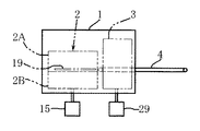
半田付け装置は、図1及び図2に示されているように、不活性ガス供給源(図示せず)から供給される不活性ガスで満たされている不活性ガス室1を有し、不活性ガス室1の内部に処理室2と冷却手段3が設置されている。不活性ガスとして本実施形態では窒素ガスが供給されている。
As shown in FIGS. 1 and 2, the soldering apparatus has an
不活性ガス室1の外部から不活性ガス室1の内部にわたって基板搬送コンベヤ4が水平に配設されている。不活性ガス室1内において、基板搬送コンベヤ4は冷却手段3が配置されている冷却ゾーンを通って処理室2の手前位置まで配置されている。基板搬送コンベヤ4はチェーンコンベヤからなっており、左右に間隔をおいて一対設けられている。不活性ガス室1の入口側の壁部には、電子部品を搭載したプリント基板5(以下、単に基板5ともいう。)を載置した基板支持フレーム6(図6参照)を載せた基板搬送コンベヤ4が通る開口が形成されている。基板搬送コンベヤ4はコンベヤチェーンの連結ピンが内側に突出しており、左右の基板搬送コンベヤ4の内側に突出している連結ピンで基板支持フレーム6の下面の左右端部を支持しながら、基板5を不活性ガス室1内の処理室2の手前位置まで搬送する。また、前記基板5を処理室2の手前位置から不活性ガス室1の外部へ搬送する。電子部品を搭載したプリント基板5は、半田付け箇所にペースト状のクリーム半田が塗られている。
A
基板搬送コンベヤ4で処理室2の手前位置まで搬送された基板5は、搬出入手段7によって処理室2へ送り込まれ、処理室2内で半田付け部の加熱溶融と脱泡処理が施される。その後、基板5は搬出入手段7によって処理室2から搬出され、基板搬送コンベヤ4に移載される。基板5はその後、冷却手段3によって半田付け部が冷却された後、基板搬送コンベヤ4によって不活性ガス室1から外部に搬出される。
The
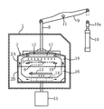
図3に示されているように、処理室2は上下に分割されて上側筐体2Aと下側筐体2Bとから構成されている。下側筐体2Bは不活性ガス室1内に固定配置されている。これに対して、上側筐体2Aは上下に移動可能に構成されている。
As shown in FIG. 3, the
上側筐体2Aは上面に連結された吊りロッド8で吊持されている。吊りロッド8は上方に延びて不活性ガス室1の上壁を上下動可能に貫通して立設されている。吊りロッド8はリンク部材9の一端部に回動可能に連結されており、リンク部材9の他端部が不活性ガス室1の外部に配置されているシリンダ装置10の進退ロッド10aの上端に回動可能に連結されている。リンク部材9は中間部が支軸11で垂直面内を回動可能に支持されている。
The
したがって、シリンダ装置10によって進退ロッド10aが上下動することにより、処理室2の上側筐体2Aが上下に移動し、上側筐体2Aが下側筐体2Bに密接する密閉状態(図3参照)と、上側筐体2Aが下側筐体2Bに対して間隔を置いて上方に配置される開放状態の2つの状態を採る。
Therefore, when the forward / backward
処理室2は加熱された雰囲気気体を循環させる熱風循環装置12を有している。熱風循環装置12は雰囲気気体を加熱するヒータ13、加熱された雰囲気気体を循環させる送風機14、送風機14を駆動するモータ15、送風機14の吐出口に接続されている導風ダクト16、熱風噴出ケーシング部材17、及び熱風噴出ケーシング部材17に接続されている導風ダクト18を有している。
The
送風機14は垂直な回転軸を有し、下側筐体2B内の底部に配置し、回転軸が不活性ガス室1の下側に配置されているモータ15の回転軸に接続されている。送風機14は上面に開口する吸入口が処理室2内に臨み、外周に開口する吐出口が導風ダクト16に接続している。導風ダクト16は送風機14の半径方向に延び、更に上方に垂直に下側筐体2Bの上端部まで延びて先端が開口している。ヒータ13は下側筐体2B内の送風機14の上方位置に配置している。
The
熱風噴出ケーシング部材17は上側筐体2A内の上部位置に配置固定されており、加熱された雰囲気気体を電子部品を搭載したプリント基板5に吹き出すための熱風噴出口を下面に複数有している。熱風噴出ケーシング部材17には導風ダクト18が接続している。導風ダクト18は熱風噴出ケーシング部材17から水平に延び、更に下方に垂直に上側筐体2Aの下端部まで延びて先端が開口している。
The hot-air
上側筐体2A内の導風ダクト18は、処理室2が密閉状態のとき、下側筐体2B内の導風ダクト16に連結される。したがって、処理室2が密閉状態のとき、ヒータ13により加熱された雰囲気気体は、送風機14により、送風機14の吸入口から吸入され、吐出口から吐出されて導風ダクト16,18内を流れ、熱風噴出ケーシング部材17内に流入し、複数の熱風噴出口から、基板支持レール19に支持された基板支持フレーム6上の電子部品を搭載したプリント基板5の上面に吹き付けられる。基板支持レール19は上側筐体2A内に左右一対、水平に設けられている。
The
電子部品を搭載したプリント基板5の上面に吹き付けられた熱風は、電子部品を搭載したプリント基板5を加熱した後、処理室2内の空間部を下方へ流れ、ヒータ13を通過して加熱され、送風機14に吸入され、吐出される。このようにして、加熱された雰囲気気体が処理室2内を循環し、電子部品を搭載したプリント基板5を加熱する。
The hot air blown on the upper surface of the printed
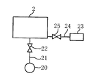
処理室2は半田付け部の脱泡が行なわれる所定の減圧雰囲気まで真空ポンプ20(図5参照)によって減圧できるように構成されている。すなわち、処理室2には真空ポンプ20が接続され、処理室2と真空ポンプ20とを接続するライン21にはラインの開閉を行う開閉バルブ22が設けられている。また、処理室2には窒素ガス供給源23が接続されており、処理室2と窒素ガス供給源23との間の接続ライン24に開閉バルブ25が設けられている。
The
したがって、電子部品を搭載したプリント基板5は、真空ポンプ20によって所定の真空雰囲気まで減圧された処理室2内で溶融半田部が脱泡される。
Accordingly, the molten solder portion of the printed
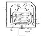
冷却手段3は図4に示されているように、不活性ガス室1内の非加熱の雰囲気気体を循環させる冷却風循環装置26を有している。冷却風循環装置26は雰囲気気体を循環させる上下一対の送風機27,28、一対の送風機27,28を駆動するモータ29、上側の送風機27の吐出口に接続されている導風ダクト30、この導風ダクト30に接続されている下側の冷却風噴出ケーシング部材31、下側の送風機28の吐出口に接続されている導風ダクト32、この導風ダクト32に接続されている上側の冷却風噴出ケーシング部材33を有している。
As shown in FIG. 4, the cooling means 3 has a cooling
上下一対の送風機27,28は垂直な共通の回転軸を有し、不活性ガス室1内の底部付近に配置し、回転軸が不活性ガス室1の下側に配置されているモータ29の回転軸に接続されている。
The pair of upper and
上側の送風機27は上面に開口する吸入口が不活性ガス室1内に臨み、外周に開口する吐出口が導風ダクト30に接続し、導風ダクト30が基板搬送コンベヤ4より下方位置に配置されている下側の冷却風噴出ケーシング部材31に接続されている。冷却風噴出ケーシング部材31は不活性ガス室1内の非加熱の雰囲気気体を電子部品を搭載したプリント基板5の下面に吹き出すための冷却風噴出口を上面に複数有している。
The
下側の送風機28は下面に開口する吸入口が不活性ガス室1内に臨み、外周に開口する吐出口が導風ダクト32に接続し、導風ダクト32が基板搬送コンベヤ4より上方位置に配置されている上側の冷却風噴出ケーシング部材33に接続されている。冷却風噴出ケーシング部材33は不活性ガス室1内の非加熱の雰囲気気体を電子部品を搭載したプリント基板5の上面に吹き出すための冷却風噴出口を下面に複数有している。
The
したがって、不活性ガス室1内の非加熱の雰囲気気体は、上側の送風機27により、送風機27の吸入口から吸入され、吐出口から吐出されて導風ダクト30内を流れ、下側の冷却風噴出ケーシング部材31内に流入し、複数の冷却風噴出口から基板搬送コンベヤ4上の電子部品を搭載したプリント基板5の下面に吹き付けられる。また、下側の送風機28により、送風機28の吸入口から吸入され、吐出口から吐出されて導風ダクト32内を流れ、上側の冷却風噴出ケーシング部材33内に流入し、複数の冷却風噴出口から基板搬送コンベヤ4上の電子部品を搭載したプリント基板5の上面に吹き付けられる。
Accordingly, the non-heated atmospheric gas in the
電子部品を搭載したプリント基板5の上下面に吹き付けられた雰囲気気体は、電子部品を搭載したプリント基板5の半田付け部を冷却した後、不活性ガス室1内の空間部を下方へ流れ、送風機27,28に吸入され、吐出される。このようにして、非加熱の雰囲気気体が不活性ガス室1内の冷却ゾーンで循環し、基板搬送コンベヤ4上の電子部品を搭載したプリント基板5の半田付け部を冷却する。
The atmospheric gas blown onto the upper and lower surfaces of the printed
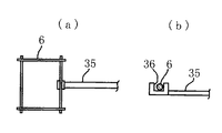
次に、基板搬送コンベヤ4上の基板支持フレーム6に載置された電子部品を搭載したプリント基板5を処理室2に搬出入する搬出入手段7を図1、図2、図6及び図7により説明する。
Next, the loading / unloading means 7 for loading / unloading the printed
図1及び図2に示されているように、不活性ガス室1の外部にチェーンコンベヤ34が配設されている。チェーンコンベヤ34は左右一対の基板搬送コンベヤ4の間の一側寄りに平行に水平に配置されている。このチェーンコンベヤ34の一側に移載ロッド35の後端部が固定されている。移載ロッド35は一対の基板搬送コンベヤ4の間の中央位置に基板搬送コンベヤ4と平行に水平に直線的に延びており、その先端部の上面に基板支持フレーム6のフレーム部分が挿入可能な凹溝36(図6参照)を有している。
As shown in FIGS. 1 and 2, a
上記搬出入手段7の作動を説明する。 The operation of the carry-in / out means 7 will be described.
基板支持フレーム6に支持された電子部品を搭載したプリント基板5は基板搬送コンベヤ4によって不活性ガス室1内の処理室2の手前位置まで搬送される。この状態から、前記基板5が処理室2内に搬入される動作は次のようにして行われる。
The printed
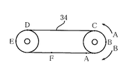
搬出入手段7のチェーンコンベヤ34が図7の矢印A方向に回転すると、チェーンコンベヤ34に固定された移載ロッド35が次のように動作して、基板5を載せた基板支持フレーム6を処理室2内に搬入する。
When the
すなわち、移載ロッド35の後端部がチェーンコンベヤ34の回転によって、図7に示すチェーンコンベヤ34のA点(搬入待機位置)からB点に移動すると、移載ロッド35は後退しながら上昇する。更に、移載ロッド35の後端部がチェーンコンベヤ34のB点からC点に移動すると、移載ロッド35は前進しながら上昇し、C点で移載ロッド35の先端部の上面の凹溝36が基板支持フレーム6の後部フレーム部分に挿入する。更に、移載ロッド35の後端部がチェーンコンベヤ34のC点からD点に進むと、移載ロッド35が基板支持フレーム6を前進させて、電子部品を搭載したプリント基板5を載せた基板支持フレーム6が処理室2内の基板支持レール19に受け渡される。
That is, when the rear end portion of the
次に、移載ロッド35の後端部がチェーンコンベヤ34のD点からE点に移動すると、移載ロッド35は下降しながら前進し、移載ロッド35の先端部の上面の凹溝36が基板支持フレーム6のフレーム部分から外れ、更にチェーンコンベヤ34の回転によってF点(搬出待機位置)に移動して待機する。
Next, when the rear end portion of the
前記基板5が処理室2内から搬出される動作は次のようにして行われる。
The operation of unloading the
搬出入手段7のチェーンコンベヤ34が図7の矢印B方向に回転すると、チェーンコンベヤ34に固定された移載ロッド35が次のように動作して、基板5を載せた基板支持フレーム6を処理室2内から搬出する。
When the
すなわち、移載ロッド35の後端部がチェーンコンベヤ34の回転によって、図7に示すチェーンコンベヤ34のF点(搬出待機位置)からE点に移動すると、移載ロッド35は前進して少し上昇する。更に、移載ロッド35の後端部がチェーンコンベヤ34のE点からD点に移動すると、移載ロッド35は後退しながら上昇し、D点で移載ロッド35の先端部の上面の凹溝36が基板支持フレーム6の後部フレーム部分に挿入する。更に、移載ロッド35の後端部がチェーンコンベヤ34のD点からC点に進むと、移載ロッド35が基板支持フレーム6を後退させて、電子部品を搭載したプリント基板5を載せた基板支持フレーム6が処理室2内の基板支持レール19から基板搬送コンベヤ4に受け渡される。
That is, when the rear end portion of the
次に、移載ロッド35の後端部がチェーンコンベヤ34のC点からB点に移動すると、移載ロッド35は下降しながら後退し、移載ロッド35の先端部の上面の凹溝36が基板支持フレーム6のフレーム部分から外れ、更にチェーンコンベヤ34の回転によってA点(搬入待機位置)に戻り、待機する。
Next, when the rear end portion of the
以下、上記半田付け装置の動作を説明する。 Hereinafter, the operation of the soldering apparatus will be described.
不活性ガス室1及び処理室2内は窒素ガスが供給されて窒素ガス雰囲気で満たされている。
The
電子部品を搭載したプリント基板5を載せた基板支持フレーム6は、基板搬送コンベヤ4に載せられ、基板搬送コンベヤ4によって不活性ガス室1内を処理室2の手前位置まで搬送され、搬出入手段7で処理室2内の基板支持レール19に移載される。このとき、処理室2の上側筐体2Aはシリンダ装置10によって下側筐体2Bに対して間隔をおいて上方に配置されている。
A
前記基板5を載せた基板支持フレーム6が処理室2内の基板支持レール19に移載されると、上側筐体2Aはシリンダ装置10によって下方に移動して下側筐体2Bに密接し、処理室2は密閉状態(図3参照)とされる。
When the
処理室2内ではヒータ13で加熱された雰囲気気体が送風機14に吸入され、吹き出されて室内を循環しており、電子部品を搭載したプリント基板5は、熱風噴出ケーシング部材17の熱風噴出口から吹き出される加熱雰囲気気体によって加熱される。
In the
電子部品を搭載したプリント基板5は処理室2内で所定時間加熱されて半田付け部が溶融される。
The printed
この後、開閉バルブ25が閉じられるとともに、真空ポンプ20の接続ライン21の開閉バルブ22が開放され、真空ポンプ20が作動する。これにより、処理室2内の窒素ガスは真空ポンプ20によって所定の真空雰囲気になるまで排気される。
Thereafter, the open /
処理室2は半田付け部の脱泡を行なえる所定の真空雰囲気で所定時間保持され、前記基板5の半田付け部が処理室2内で所定時間、脱泡処理される。
The
その後、開閉バルブ22が閉じられ、開閉バルブ25が開放され、窒素ガス供給源23から窒素ガスが処理室2内に供給される。次に、上側筐体2Aがシリンダ装置10によって上方に移動し、下側筐体2Bに対して間隔をおいて上方に配置された後、前記基板5を載せた基板支持フレーム6は搬出入手段7によって処理室2から基板搬送コンベヤ4に移載される。不活性ガス室1内の冷却手段3が設けられている冷却ゾーンでは、不活性ガス室1内の非加熱の雰囲気気体が送風機27,28に吸入され、吹き出されて循環しており、基板搬送コンベヤ4上の前記基板5は冷却ゾーンで、半田付け部が上下の冷却風噴出ケーシング部材31,33の冷却風噴出口から吹き出される雰囲気気体によって所定時間冷却される。冷却後、基板搬送コンベヤ4上の電子部品を搭載したプリント基板5は不活性ガス室1から外部に搬出される。
Thereafter, the opening / closing
以上に述べた通り、電子部品を搭載したプリント基板5は半田付け部が処理室2内を循環する加熱雰囲気気体で加熱溶融され、その後、減圧された処理室2内で脱泡処理される。前記基板5は、その後、処理室2から搬出され、不活性ガス室1内の冷却手段3が設けられている冷却ゾーンで循環する非加熱の雰囲気気体で半田付け部が冷却固化され、電子部品が基板上に半田付けされる。
As described above, the printed
1・・不活性ガス室、2・・処理室、2A・・上側筐体、2B・・下側筐体、3・・冷却手段、4・・基板搬送コンベヤ、5・・電子部品を搭載したプリント基板、6・・基板支持フレーム、7・・搬出入手段、8・・吊りロッド、9・・リンク部材、10・・シリンダ装置、10a・・進退ロッド、11・・支軸、12・・熱風循環装置、13・・ヒータ、14・・送風機、15・・モータ、16・・導風ダクト、17・・熱風噴出ケーシング部材、18・・導風ダクト、19・・基板支持レール、20・・真空ポンプ、21・・接続ライン、22・・開閉バルブ、23・・窒素ガス供給源、24・・接続ライン、25・・開閉バルブ、26・・冷却風循環装置、27,28・・送風機、29・・モータ、30・・導風ダクト、31・・下側の冷却風噴出ケーシング部材、32・・導風ダクト、33・・上側の冷却風噴出ケーシング部材、34・・チェーンコンベヤ、35・・移載ロッド、36・・凹溝。 1 .... Inert gas chamber, 2 .... Processing chamber, 2A ... Upper casing, 2B ... Lower casing, 3 .... Cooling means, 4 .... Board conveyor, 5 .... Equipped with electronic parts Printed circuit board, 6 ... Board support frame, 7 ... Loading / unloading means, 8 ... Hanging rod, 9 ... Link member, 10 ... Cylinder device, 10a ... Advancing / retracting rod, 11 .... Support shaft, ... Hot air circulation device, 13 ... Heater, 14 ... Blower, 15 ... Motor, 16 ... Air guide duct, 17 ... Hot air jet casing member, 18 ... Air guide duct, 19 ... Board support rail, 20 ...・ Vacuum pump, 21 ・ ・ Connection line, 22 ・ ・ Open / close valve, 23 ・ ・ Nitrogen gas supply source, 24 ・ ・ Connection line, 25 ・ ・ Open / close valve, 26 ・ ・ Cooling air circulation device, 27, 28 ・ ・ Blower , 29 .. Motor, 30 .. Air duct, 31. Cooling air blowing casing member, 32 ... guide duct, 33 ... upper cooling air blowing casing member, 34 ... chain conveyor, 35 ... transfer rod, 36 ... groove.
Claims (4)
半田付け部を加熱溶融する手段が設けられ、前記手段で半田付け部を加熱溶融後、減圧雰囲気で脱泡処理を行う処理室と、
前記処理室から搬出された部材の半田付け部を冷却する手段とを有し、
前記処理室と冷却手段が不活性ガスで満たされている不活性ガス室の内部に設置され、
前記冷却手段は、前記不活性ガス室内の非加熱の雰囲気気体を循環させる冷却風循環装置を有し、該冷却風循環装置は雰囲気気体を循環させる上下一対の送風機と、該送風機の上側の吐出口に接続されている導風ダクトと、該導風ダクトに接続されている下側の冷却風噴出ケーシング部材と、該送風機の下側の吐出口に接続されている導風ダクトと、該導風ダクトに接続されている上側の冷却風噴出ケーシング部材とを有しており、雰囲気気体が前記送風機により前記上側の冷却風噴出ケーシング部材および前記下側の冷却風噴出ケーシング部材から半田付け部の上面および下面に吹出して半田付け部を冷却することを特徴とする半田付け装置。 In the soldering apparatus that heats and melts the soldering part between the two members, then defoams in a reduced-pressure atmosphere, and then cools it.
A means for heating and melting the soldering part is provided, and a processing chamber for performing defoaming treatment in a reduced pressure atmosphere after heating and melting the soldering part by the means;
Means for cooling the soldering part of the member carried out of the processing chamber,
The processing chamber and the cooling means are installed inside an inert gas chamber filled with an inert gas,
The cooling means includes a cooling air circulation device that circulates an unheated atmospheric gas in the inert gas chamber, and the cooling air circulation device includes a pair of upper and lower blowers that circulate the atmospheric gas, and an upper discharge of the blower. An air guide duct connected to the outlet, a lower cooling air jet casing member connected to the air guide duct, an air guide duct connected to the lower discharge port of the blower, and the guide An upper cooling air jet casing member connected to the air duct, and the atmosphere gas is sent from the upper cooling air jet casing member and the lower cooling air jet casing member to the soldering portion by the blower . A soldering apparatus which cools a soldering part by blowing to an upper surface and a lower surface .
Priority Applications (2)
| Application Number | Priority Date | Filing Date | Title |
|---|---|---|---|
| JP2011120220A JP5868614B2 (en) | 2011-05-30 | 2011-05-30 | Soldering device |
| PCT/JP2011/079152 WO2012164776A1 (en) | 2011-05-30 | 2011-12-16 | Soldering device |
Applications Claiming Priority (1)
| Application Number | Priority Date | Filing Date | Title |
|---|---|---|---|
| JP2011120220A JP5868614B2 (en) | 2011-05-30 | 2011-05-30 | Soldering device |
Publications (2)
| Publication Number | Publication Date |
|---|---|
| JP2012245553A JP2012245553A (en) | 2012-12-13 |
| JP5868614B2 true JP5868614B2 (en) | 2016-02-24 |
Family
ID=47258656
Family Applications (1)
| Application Number | Title | Priority Date | Filing Date |
|---|---|---|---|
| JP2011120220A Active JP5868614B2 (en) | 2011-05-30 | 2011-05-30 | Soldering device |
Country Status (2)
| Country | Link |
|---|---|
| JP (1) | JP5868614B2 (en) |
| WO (1) | WO2012164776A1 (en) |
Families Citing this family (4)
| Publication number | Priority date | Publication date | Assignee | Title |
|---|---|---|---|---|
| JP2014157858A (en) * | 2013-02-14 | 2014-08-28 | Fuji Electric Co Ltd | Semiconductor device manufacturing method |
| JP5601436B1 (en) * | 2013-12-25 | 2014-10-08 | 千住金属工業株式会社 | Vacuum solder processing apparatus and control method thereof |
| CN109068492B (en) * | 2018-10-31 | 2020-11-24 | 江苏盛凡信息服务有限公司 | Integrated circuit board processing machine |
| US11862482B2 (en) * | 2021-03-11 | 2024-01-02 | Taiwan Semiconductor Manufacturing Company, Ltd. | Semiconductor substrate bonding tool and methods of operation |
Family Cites Families (6)
| Publication number | Priority date | Publication date | Assignee | Title |
|---|---|---|---|---|
| JPH06226484A (en) * | 1993-02-04 | 1994-08-16 | Koyo Rindobaagu Kk | Heat treatment device |
| JP3617188B2 (en) * | 1996-05-23 | 2005-02-02 | 富士電機機器制御株式会社 | Soldering method |
| JP2004181483A (en) * | 2002-12-03 | 2004-07-02 | Senju Metal Ind Co Ltd | Reflow furnace |
| JP4200000B2 (en) * | 2002-12-26 | 2008-12-24 | パナソニック株式会社 | Reflow soldering method and soldering apparatus |
| JP2007000915A (en) * | 2005-06-27 | 2007-01-11 | Shinko Seiki Co Ltd | Soldering method and soldering device |
| JP5343566B2 (en) * | 2009-01-08 | 2013-11-13 | 富士通株式会社 | Joining method and reflow apparatus |
-
2011
- 2011-05-30 JP JP2011120220A patent/JP5868614B2/en active Active
- 2011-12-16 WO PCT/JP2011/079152 patent/WO2012164776A1/en active Application Filing
Also Published As
| Publication number | Publication date |
|---|---|
| WO2012164776A1 (en) | 2012-12-06 |
| JP2012245553A (en) | 2012-12-13 |
Similar Documents
| Publication | Publication Date | Title |
|---|---|---|
| WO2012086533A1 (en) | Reflow soldering apparatus and method therefor | |
| JP5801047B2 (en) | Reflow soldering apparatus and method | |
| JP5868614B2 (en) | Soldering device | |
| JP2011171714A5 (en) | ||
| JP4082462B1 (en) | Reflow furnace | |
| JP5075806B2 (en) | Reflow soldering equipment | |
| JP2011245527A (en) | Treatment device | |
| JP2012245552A (en) | Soldering method | |
| JP2003324272A (en) | Reflow furnace | |
| JP5975165B1 (en) | Lid opening / closing mechanism and soldering device | |
| JP2018162932A (en) | Reflow device | |
| JP4092258B2 (en) | Reflow furnace and temperature control method for reflow furnace | |
| JP2003332726A (en) | Reflow furnace, flux recovering device connected to the furnace, and method of operating the device | |
| KR100691851B1 (en) | Vacuum absorption device for transferring hot plate | |
| JP3592033B2 (en) | Reflow soldering method and apparatus | |
| JP6687495B2 (en) | Component mounting line | |
| JP3582989B2 (en) | Reflow soldering equipment | |
| JP5216222B2 (en) | Heating device | |
| JPH1168303A (en) | Reflow soldering device | |
| KR20240041754A (en) | Reflow soldering machine | |
| JP2008053655A (en) | Soldering device and method | |
| JPH0653644A (en) | Soldering apparatus | |
| JP2016176661A (en) | Firing furnace and coating method | |
| KR100685656B1 (en) | A nozzle for reflow soldering apparatus | |
| JPH04274868A (en) | Method and device for reflow soldering |
Legal Events
| Date | Code | Title | Description |
|---|---|---|---|
| A621 | Written request for application examination |
Free format text: JAPANESE INTERMEDIATE CODE: A621 Effective date: 20140319 |
|
| RD03 | Notification of appointment of power of attorney |
Free format text: JAPANESE INTERMEDIATE CODE: A7423 Effective date: 20141208 |
|
| RD04 | Notification of resignation of power of attorney |
Free format text: JAPANESE INTERMEDIATE CODE: A7424 Effective date: 20141222 |
|
| A521 | Request for written amendment filed |
Free format text: JAPANESE INTERMEDIATE CODE: A523 Effective date: 20150120 |
|
| A131 | Notification of reasons for refusal |
Free format text: JAPANESE INTERMEDIATE CODE: A131 Effective date: 20150630 |
|
| A521 | Request for written amendment filed |
Free format text: JAPANESE INTERMEDIATE CODE: A523 Effective date: 20150831 |
|
| TRDD | Decision of grant or rejection written | ||
| A01 | Written decision to grant a patent or to grant a registration (utility model) |
Free format text: JAPANESE INTERMEDIATE CODE: A01 Effective date: 20151211 |
|
| A61 | First payment of annual fees (during grant procedure) |
Free format text: JAPANESE INTERMEDIATE CODE: A61 Effective date: 20160106 |
|
| R150 | Certificate of patent or registration of utility model |
Ref document number: 5868614 Country of ref document: JP Free format text: JAPANESE INTERMEDIATE CODE: R150 |
|
| R250 | Receipt of annual fees |
Free format text: JAPANESE INTERMEDIATE CODE: R250 |
|
| R250 | Receipt of annual fees |
Free format text: JAPANESE INTERMEDIATE CODE: R250 |
|
| R250 | Receipt of annual fees |
Free format text: JAPANESE INTERMEDIATE CODE: R250 |
|
| R250 | Receipt of annual fees |
Free format text: JAPANESE INTERMEDIATE CODE: R250 |
|
| R250 | Receipt of annual fees |
Free format text: JAPANESE INTERMEDIATE CODE: R250 |
|
| R250 | Receipt of annual fees |
Free format text: JAPANESE INTERMEDIATE CODE: R250 |

