JP5848589B2 - 位置検出装置および位置検出方法 - Google Patents
位置検出装置および位置検出方法 Download PDFInfo
- Publication number
- JP5848589B2 JP5848589B2 JP2011264871A JP2011264871A JP5848589B2 JP 5848589 B2 JP5848589 B2 JP 5848589B2 JP 2011264871 A JP2011264871 A JP 2011264871A JP 2011264871 A JP2011264871 A JP 2011264871A JP 5848589 B2 JP5848589 B2 JP 5848589B2
- Authority
- JP
- Japan
- Prior art keywords
- indicator
- sensor
- signal
- situation
- circuit
- Prior art date
- Legal status (The legal status is an assumption and is not a legal conclusion. Google has not performed a legal analysis and makes no representation as to the accuracy of the status listed.)
- Active
Links
- 238000001514 detection method Methods 0.000 title claims description 232
- 230000005540 biological transmission Effects 0.000 claims description 166
- 230000005674 electromagnetic induction Effects 0.000 claims description 76
- 238000000034 method Methods 0.000 claims description 43
- 230000007704 transition Effects 0.000 claims description 20
- 230000004044 response Effects 0.000 claims description 13
- 230000001360 synchronised effect Effects 0.000 claims 1
- 230000008569 process Effects 0.000 description 22
- 238000006243 chemical reaction Methods 0.000 description 21
- 230000000694 effects Effects 0.000 description 16
- 238000012545 processing Methods 0.000 description 16
- 230000002411 adverse Effects 0.000 description 13
- 239000000758 substrate Substances 0.000 description 13
- 230000008859 change Effects 0.000 description 8
- 238000010586 diagram Methods 0.000 description 7
- 230000007274 generation of a signal involved in cell-cell signaling Effects 0.000 description 4
- 239000004973 liquid crystal related substance Substances 0.000 description 4
- 230000002093 peripheral effect Effects 0.000 description 4
- 230000003321 amplification Effects 0.000 description 3
- 238000010168 coupling process Methods 0.000 description 3
- 230000005284 excitation Effects 0.000 description 3
- 230000006698 induction Effects 0.000 description 3
- 238000003199 nucleic acid amplification method Methods 0.000 description 3
- 238000011112 process operation Methods 0.000 description 3
- 239000003990 capacitor Substances 0.000 description 2
- 239000004020 conductor Substances 0.000 description 2
- 230000008878 coupling Effects 0.000 description 2
- 238000005859 coupling reaction Methods 0.000 description 2
- 230000006866 deterioration Effects 0.000 description 2
- 239000011521 glass Substances 0.000 description 2
- 230000004048 modification Effects 0.000 description 2
- 238000012986 modification Methods 0.000 description 2
- 229920005989 resin Polymers 0.000 description 2
- 239000011347 resin Substances 0.000 description 2
- RYGMFSIKBFXOCR-UHFFFAOYSA-N Copper Chemical compound [Cu] RYGMFSIKBFXOCR-UHFFFAOYSA-N 0.000 description 1
- 239000000853 adhesive Substances 0.000 description 1
- 230000001070 adhesive effect Effects 0.000 description 1
- 238000013459 approach Methods 0.000 description 1
- 239000013256 coordination polymer Substances 0.000 description 1
- 239000011889 copper foil Substances 0.000 description 1
- 230000002349 favourable effect Effects 0.000 description 1
- 239000011810 insulating material Substances 0.000 description 1
- 238000012544 monitoring process Methods 0.000 description 1
- 238000007650 screen-printing Methods 0.000 description 1
- 230000035945 sensitivity Effects 0.000 description 1
- 230000007480 spreading Effects 0.000 description 1
- 230000003068 static effect Effects 0.000 description 1
- 229920003002 synthetic resin Polymers 0.000 description 1
- 239000000057 synthetic resin Substances 0.000 description 1
- 239000012780 transparent material Substances 0.000 description 1
Images
Classifications
-
- G—PHYSICS
- G06—COMPUTING; CALCULATING OR COUNTING
- G06F—ELECTRIC DIGITAL DATA PROCESSING
- G06F3/00—Input arrangements for transferring data to be processed into a form capable of being handled by the computer; Output arrangements for transferring data from processing unit to output unit, e.g. interface arrangements
- G06F3/01—Input arrangements or combined input and output arrangements for interaction between user and computer
- G06F3/03—Arrangements for converting the position or the displacement of a member into a coded form
- G06F3/041—Digitisers, e.g. for touch screens or touch pads, characterised by the transducing means
- G06F3/046—Digitisers, e.g. for touch screens or touch pads, characterised by the transducing means by electromagnetic means
-
- G—PHYSICS
- G06—COMPUTING; CALCULATING OR COUNTING
- G06F—ELECTRIC DIGITAL DATA PROCESSING
- G06F3/00—Input arrangements for transferring data to be processed into a form capable of being handled by the computer; Output arrangements for transferring data from processing unit to output unit, e.g. interface arrangements
- G06F3/01—Input arrangements or combined input and output arrangements for interaction between user and computer
- G06F3/03—Arrangements for converting the position or the displacement of a member into a coded form
- G06F3/041—Digitisers, e.g. for touch screens or touch pads, characterised by the transducing means
- G06F3/0416—Control or interface arrangements specially adapted for digitisers
-
- G—PHYSICS
- G06—COMPUTING; CALCULATING OR COUNTING
- G06F—ELECTRIC DIGITAL DATA PROCESSING
- G06F3/00—Input arrangements for transferring data to be processed into a form capable of being handled by the computer; Output arrangements for transferring data from processing unit to output unit, e.g. interface arrangements
- G06F3/01—Input arrangements or combined input and output arrangements for interaction between user and computer
- G06F3/03—Arrangements for converting the position or the displacement of a member into a coded form
- G06F3/041—Digitisers, e.g. for touch screens or touch pads, characterised by the transducing means
- G06F3/044—Digitisers, e.g. for touch screens or touch pads, characterised by the transducing means by capacitive means
- G06F3/0446—Digitisers, e.g. for touch screens or touch pads, characterised by the transducing means by capacitive means using a grid-like structure of electrodes in at least two directions, e.g. using row and column electrodes
Landscapes
- Engineering & Computer Science (AREA)
- General Engineering & Computer Science (AREA)
- Theoretical Computer Science (AREA)
- Physics & Mathematics (AREA)
- Human Computer Interaction (AREA)
- General Physics & Mathematics (AREA)
- Electromagnetism (AREA)
- Position Input By Displaying (AREA)
- Near-Field Transmission Systems (AREA)
- Train Traffic Observation, Control, And Security (AREA)
- Measurement Of Length, Angles, Or The Like Using Electric Or Magnetic Means (AREA)
Description
電磁誘導方式によって第1の指示体による位置指示を検出するための第1のセンサと、前記第1のセンサに近接して配置されると共に、前記電磁誘導方式以外の検出方式で第2の指示体による位置指示を検出するための第2のセンサとを備え、前記第1の指示体および前記第2の指示体による位置指示を同時に検出可能な位置検出装置であって、
前記第2のセンサに前記第2の指示体による位置指示を検出するための送信信号を供給する信号供給回路と、
前記第1の指示体による位置指示に対応して前記第1のセンサから出力される信号と、前記第2の指示体による位置指示に対応して前記第2のセンサから出力される信号が供給されて、前記第1の指示体と前記第2の指示体とによる位置指示状況を判別する位置指示状況判別回路と、
前記位置指示状況判別回路による前記位置指示状況の判別結果に対応して、前記信号供給回路から前記第2のセンサに供給される前記送信信号の信号レベルを制御する信号レベル制御回路と、
を備えており、
前記位置指示状況判別回路によって判別された前記位置指示状況に基づいて、前記第1の指示体と前記第2の指示体が互いに非同時的位置指示の状況から、前記第1の指示体と前記第2の指示体が同時的位置指示の状況に遷移した際には、前記信号レベル制御回路によって、前記第1の指示体と前記第2の指示体が互いに非同時的位置指示の状況において前記第2のセンサに供給される送信信号の信号レベルよりも信号レベルが異なる送信信号を前記第2のセンサに供給して前記第2の指示体による位置指示を検出するようにした
ことを特徴とする位置検出装置を提供する。
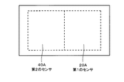
図1は、この発明による位置検出装置の第1の実施形態を搭載する電子機器の構成例を示す分解構成図である。この図1の例では、電子機器は、例えば電子ペンなどの位置指示器からなる電磁誘導方式用の指示体(以下、第1の指示体という)によって指示された位置を電磁誘導方式の位置検出用のセンサ(以下、第1のセンサと称する)で検出する機能を備えると共に、表示デバイスの表示画面への指や位置指示器(静電ペン)などの指示体(以下、第2の指示体という)よって指示された位置を静電容量方式の位置検出用のセンサ(以下、第2のセンサと称する)で検出する機能を備え、両センサで、同時に第1および第2の指示体による位置指示を検出することができるパッド型端末である。
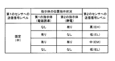
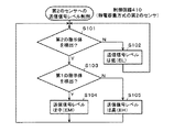
この第1の実施形態の位置検出装置では、静電容量方式の第2のセンサ40に供給する送信信号が電磁誘導方式の第1のセンサ20の位置検出回路200へ及ぼす悪影響を、第2のセンサ40に供給する送信信号の信号レベルを位置指示状況判別回路411による位置指示状況の判別結果に対応して制御することにより軽減する。
上述の第1の実施形態では、電磁誘導方式の第1のセンサ20および位置検出回路200におけるジッタを軽減させるために、第2のセンサ40に供給される送信信号の信号レベルのみを制御するようにした。
この第3の実施形態は、第2の実施形態の変形例である。すなわち、上述した第2の実施形態では、位置検出回路200の制御回路210と位置検出回路400の制御回路410のそれぞれが、位置指示状況判別回路の機能を備え、それぞれ、制御コードCP1、CP2を別個に生成するようにした。
上述の第1の実施形態では、電磁誘導方式の第1のセンサ20および位置検出回路200におけるジッタ性能の悪化を軽減させるために、第2のセンサ40に供給する送信信号の信号レベルを低くするように制御するようにした。
以上説明した電磁誘導方式の第1のセンサは、X軸方向に配列されたループコイル群と、Y軸方向に配列されたループコイル群の一方を、電子ペンに電磁誘導信号を供給するコイルとして用いるようにしたが、電磁誘導方式の第1のセンサは、このようなタイプのものに限られるものではない。
Claims (7)
- 電磁誘導方式によって第1の指示体による位置指示を検出するための第1のセンサと、前記第1のセンサに近接して配置されると共に、前記電磁誘導方式以外の検出方式で第2の指示体による位置指示を検出するための第2のセンサとを備え、前記第1の指示体および前記第2の指示体による位置指示を同時に検出可能な位置検出装置であって、
前記第2のセンサに前記第2の指示体による位置指示を検出するための送信信号を供給する信号供給回路と、
前記第1の指示体による位置指示に対応して前記第1のセンサから出力される信号と、前記第2の指示体による位置指示に対応して前記第2のセンサから出力される信号が供給されて、前記第1の指示体と前記第2の指示体とによる位置指示状況を判別する位置指示状況判別回路と、
前記位置指示状況判別回路による前記位置指示状況の判別結果に対応して、前記信号供給回路から前記第2のセンサに供給される前記送信信号の信号レベルを制御する信号レベル制御回路と、
を備えており、
前記位置指示状況判別回路によって判別された前記位置指示状況に基づいて、前記第1の指示体と前記第2の指示体が互いに非同時的位置指示の状況から、前記第1の指示体と前記第2の指示体が同時的位置指示の状況に遷移した際には、前記信号レベル制御回路によって、前記第1の指示体と前記第2の指示体が互いに非同時的位置指示の状況において前記第2のセンサに供給される送信信号の信号レベルよりも信号レベルが異なる送信信号を前記第2のセンサに供給して前記第2の指示体による位置指示を検出するようにした
ことを特徴とする位置検出装置。 - 前記第1の指示体と前記第2の指示体が互いに非同時的位置指示の状況とは、前記第2の指示体が位置指示の状況にあり、前記状況から前記第1の指示体と前記第2の指示体が同時的位置指示の状況に遷移した際には、前記信号レベル制御回路によって、前記第2の指示体が位置指示の状況において前記第2のセンサに供給される送信信号の信号レベルよりも信号レベルが低く設定された送信信号を前記第2のセンサに供給して前記第2の指示体による位置指示を検出するようにした
ことを特徴とする請求項1に記載の位置検出装置。 - 前記第1の指示体と前記第2の指示体が互いに非同時的位置指示の状況とは、前記第1の指示体が位置指示の状況にあり、前記状況から前記第1の指示体と前記第2の指示体が同時的位置指示の状況に遷移した際には、前記信号レベル制御回路によって、前記第1の指示体が位置指示の状況において前記第2のセンサに供給される送信信号の信号レベルよりも信号レベルが高く設定された送信信号を前記第2のセンサに供給して前記第2の指示体による位置指示を検出するようにした
ことを特徴とする請求項1に記載の位置検出装置。 - 前記第1の指示体はコイルを有しており、前記コイルに対してワイヤレスにて電磁誘導信号を供給するための電磁誘導信号供給回路をさらに備え、
前記信号レベル制御回路は、前記位置指示状況判別回路による前記位置指示状況の判別結果に対応して、前記電磁誘導信号供給回路から第1の指示体に供給される前記電磁誘導信号の信号レベルを制御するようにした
ことを特徴とする請求項1に記載の位置検出装置。 - 前記電磁誘導信号供給回路は、前記第1の指示体が有するコイルに対して前記電磁誘導信号を供給するためのコイルを備えている
ことを特徴とする請求項4に記載の位置検出装置。 - 前記第1のセンサと前記第2のセンサは、互いに重畳されて配置されている
ことを特徴とする請求項1に記載の位置検出装置。 - 電磁誘導方式によって第1の指示体による位置指示を検出するための第1のセンサと、前記第1のセンサに近接して配置されると共に、前記電磁誘導方式以外の検出方式で第2の指示体による位置指示を検出するための第2のセンサとを備え、前記第1の指示体および前記第2の指示体による位置指示を同時に検出可能な位置検出方法であって、
前記第2のセンサに前記第2の指示体による位置指示を検出するための送信信号を供給する信号供給ステップと、
前記第1の指示体による位置指示に対応して前記第1のセンサから出力される信号と、前記第2の指示体による位置指示に対応して前記第2のセンサから出力される信号が供給されて、前記第1の指示体と前記第2の指示体による位置指示状況を判別する位置指示状況判別ステップと、
前記位置指示状況判別ステップによる前記位置指示状況の判別結果に対応して、前記信号供給ステップによって前記第2のセンサに供給される前記送信信号の信号レベルを制御する信号レベル制御ステップと、を備えており、
前記位置指示状況判別ステップによって判別された前記位置指示状況に基づいて、前記第1の指示体と前記第2の指示体が互いに非同時的位置指示の状況から、前記第1の指示体と前記第2の指示体が同時的位置指示の状況に遷移した際には、前記信号レベル制御ステップによって、前記第1の指示体と前記第2の指示体が互いに非同時的位置指示の状況において前記第2のセンサに供給される送信信号の信号レベルよりも信号レベルが異なる送信信号を前記第2のセンサに供給して前記第2の指示体による位置指示を検出するようにした
ことを特徴とする位置検出方法。
Priority Applications (8)
| Application Number | Priority Date | Filing Date | Title |
|---|---|---|---|
| JP2011264871A JP5848589B2 (ja) | 2011-12-02 | 2011-12-02 | 位置検出装置および位置検出方法 |
| IL222694A IL222694A (en) | 2011-12-02 | 2012-10-25 | Location detector and method for detecting location |
| TW101140298A TWI579738B (zh) | 2011-12-02 | 2012-10-31 | 位置檢測裝置及位置檢測方法 |
| US13/665,502 US8766624B2 (en) | 2011-12-02 | 2012-10-31 | Position detector and position detection method |
| CN2012206025738U CN203133780U (zh) | 2011-12-02 | 2012-11-14 | 位置检测装置 |
| CN201210458922.8A CN103135838B (zh) | 2011-12-02 | 2012-11-14 | 位置检测装置及位置检测方法 |
| KR1020120135528A KR20130062229A (ko) | 2011-12-02 | 2012-11-27 | 위치 검출 장치 및 위치 검출 방법 |
| EP12195069.5A EP2600230B1 (en) | 2011-12-02 | 2012-11-30 | Position detector and position detection method |
Applications Claiming Priority (1)
| Application Number | Priority Date | Filing Date | Title |
|---|---|---|---|
| JP2011264871A JP5848589B2 (ja) | 2011-12-02 | 2011-12-02 | 位置検出装置および位置検出方法 |
Publications (3)
| Publication Number | Publication Date |
|---|---|
| JP2013117846A JP2013117846A (ja) | 2013-06-13 |
| JP2013117846A5 JP2013117846A5 (ja) | 2015-01-22 |
| JP5848589B2 true JP5848589B2 (ja) | 2016-01-27 |
Family
ID=47325903
Family Applications (1)
| Application Number | Title | Priority Date | Filing Date |
|---|---|---|---|
| JP2011264871A Active JP5848589B2 (ja) | 2011-12-02 | 2011-12-02 | 位置検出装置および位置検出方法 |
Country Status (7)
| Country | Link |
|---|---|
| US (1) | US8766624B2 (ja) |
| EP (1) | EP2600230B1 (ja) |
| JP (1) | JP5848589B2 (ja) |
| KR (1) | KR20130062229A (ja) |
| CN (2) | CN103135838B (ja) |
| IL (1) | IL222694A (ja) |
| TW (1) | TWI579738B (ja) |
Families Citing this family (10)
| Publication number | Priority date | Publication date | Assignee | Title |
|---|---|---|---|---|
| JP5848589B2 (ja) * | 2011-12-02 | 2016-01-27 | 株式会社ワコム | 位置検出装置および位置検出方法 |
| JP6249486B2 (ja) * | 2013-08-19 | 2017-12-20 | 株式会社ワコム | 描画装置 |
| US9158427B1 (en) * | 2014-03-25 | 2015-10-13 | Netio Technologies Co., Ltd. | Electromagnetic sensing touch screen |
| EP3151094B1 (en) * | 2014-05-27 | 2019-04-24 | Wacom Co., Ltd. | Indicator detection device and signal processing method thereof |
| TWI544391B (zh) * | 2014-06-09 | 2016-08-01 | 義隆電子股份有限公司 | 具有接近感應功能之電容式觸控面板及其掃描方法 |
| JP6923995B2 (ja) * | 2014-09-24 | 2021-08-25 | 任天堂株式会社 | 情報処理システム、情報処理装置、情報処理プログラム、および情報処理方法 |
| TWI599933B (zh) * | 2016-09-21 | 2017-09-21 | 奕力科技股份有限公司 | 觸控感測裝置 |
| JP7079838B2 (ja) | 2018-02-13 | 2022-06-02 | 株式会社ワコム | 位置検出装置、ならびに電磁誘導結合及び静電結合に基づく位置検出方法 |
| JP2020187427A (ja) | 2019-05-10 | 2020-11-19 | 株式会社ジャパンディスプレイ | センサ装置 |
| WO2021161701A1 (ja) | 2020-02-10 | 2021-08-19 | 株式会社ワコム | ポインタの位置検出方法及びセンサコントローラ |
Family Cites Families (20)
| Publication number | Priority date | Publication date | Assignee | Title |
|---|---|---|---|---|
| JPH09138730A (ja) * | 1995-11-14 | 1997-05-27 | Sharp Corp | 情報入力処理装置 |
| US6498590B1 (en) | 2001-05-24 | 2002-12-24 | Mitsubishi Electric Research Laboratories, Inc. | Multi-user touch surface |
| JP4126610B2 (ja) | 2002-12-26 | 2008-07-30 | エルジー ディスプレイ カンパニー リミテッド | 液晶表示装置 |
| DE202004021638U1 (de) * | 2003-02-10 | 2009-12-31 | N-Trig Ltd. | Berührungsdetektion für einen Digitalisierer |
| US20050052427A1 (en) * | 2003-09-10 | 2005-03-10 | Wu Michael Chi Hung | Hand gesture interaction with touch surface |
| WO2007129085A2 (en) * | 2006-05-09 | 2007-11-15 | Sensopad Limited | Navigation arrangement for an electronic device |
| JP4915232B2 (ja) * | 2006-12-19 | 2012-04-11 | ソニー株式会社 | 座標入力装置及び座標入力システム |
| JP5094376B2 (ja) * | 2007-12-28 | 2012-12-12 | 株式会社ワコム | 位置検出装置 |
| CN101551713A (zh) * | 2008-03-31 | 2009-10-07 | 太瀚科技股份有限公司 | 具有双重输入模式的指针输入装置 |
| JP2009265759A (ja) * | 2008-04-22 | 2009-11-12 | Wacom Co Ltd | 位置検出装置及び位置検出用部品 |
| WO2009140347A2 (en) * | 2008-05-14 | 2009-11-19 | 3M Innovative Properties Company | Systems and methods for assessing locations of multiple touch inputs |
| CN101667085A (zh) * | 2008-09-04 | 2010-03-10 | 汉王科技股份有限公司 | 双模式输入装置 |
| CN201247458Y (zh) * | 2008-09-04 | 2009-05-27 | 汉王科技股份有限公司 | 一种具有双模式输入功能的显示装置 |
| JP2011003034A (ja) | 2009-06-18 | 2011-01-06 | Toshiba Corp | 電力系統監視制御装置、その制御方法及び制御プログラム |
| JP5427070B2 (ja) * | 2010-03-05 | 2014-02-26 | 株式会社ワコム | 位置検出装置 |
| TWI470530B (zh) * | 2011-02-01 | 2015-01-21 | Hungta Liu | 觸控感應元件暨其觸控顯示器相關裝置及其觸控驅動方法 |
| TWI437474B (zh) * | 2010-12-16 | 2014-05-11 | Hongda Liu | 雙模式觸控感應元件暨其觸控顯示器相關裝置及其觸控驅動方法 |
| TW201250530A (en) * | 2011-06-07 | 2012-12-16 | Hannstar Display Corp | Integrated touch panel structure and manufacturing method thereof |
| TWI447610B (zh) * | 2011-11-25 | 2014-08-01 | Spatial location detection method and system of subject matter | |
| JP5848589B2 (ja) * | 2011-12-02 | 2016-01-27 | 株式会社ワコム | 位置検出装置および位置検出方法 |
-
2011
- 2011-12-02 JP JP2011264871A patent/JP5848589B2/ja active Active
-
2012
- 2012-10-25 IL IL222694A patent/IL222694A/en active IP Right Grant
- 2012-10-31 TW TW101140298A patent/TWI579738B/zh active
- 2012-10-31 US US13/665,502 patent/US8766624B2/en active Active
- 2012-11-14 CN CN201210458922.8A patent/CN103135838B/zh active Active
- 2012-11-14 CN CN2012206025738U patent/CN203133780U/zh not_active Expired - Lifetime
- 2012-11-27 KR KR1020120135528A patent/KR20130062229A/ko not_active Application Discontinuation
- 2012-11-30 EP EP12195069.5A patent/EP2600230B1/en active Active
Also Published As
| Publication number | Publication date |
|---|---|
| JP2013117846A (ja) | 2013-06-13 |
| CN103135838A (zh) | 2013-06-05 |
| CN103135838B (zh) | 2017-09-12 |
| EP2600230A2 (en) | 2013-06-05 |
| TWI579738B (zh) | 2017-04-21 |
| US8766624B2 (en) | 2014-07-01 |
| IL222694A (en) | 2016-12-29 |
| TW201342146A (zh) | 2013-10-16 |
| US20130141085A1 (en) | 2013-06-06 |
| EP2600230A3 (en) | 2015-01-21 |
| EP2600230B1 (en) | 2018-10-03 |
| CN203133780U (zh) | 2013-08-14 |
| KR20130062229A (ko) | 2013-06-12 |
Similar Documents
| Publication | Publication Date | Title |
|---|---|---|
| JP5848589B2 (ja) | 位置検出装置および位置検出方法 | |
| JP6156948B2 (ja) | 干渉を防止するための復調の変更 | |
| JP5427070B2 (ja) | 位置検出装置 | |
| US10175791B2 (en) | Display device with integrated touch screen | |
| JP5060845B2 (ja) | 画面入力型画像表示装置 | |
| US9971451B2 (en) | Driving chip, circuit film, chip-on-film type driving circuit, and display device having built-in touchscreen | |
| JP6042763B2 (ja) | タッチ検出機能付き表示装置及び電子機器 | |
| KR20130140323A (ko) | 터치 스크린 일체형 표시장치 | |
| US10162454B2 (en) | Touch display apparatus and operation method thereof | |
| JP2016105334A (ja) | タッチ感知システム及び表示装置 | |
| US20100110029A1 (en) | Position detecting device | |
| JP2017525075A (ja) | 向上したタッチ感知性能を有する座標入力装置 | |
| US10345983B2 (en) | Detection apparatus, inputting apparatus, and detection method in which switch circuit is controlled to cause first and second signals to be supplied to first and second sensor electrodes, respectively | |
| JP2018185559A (ja) | タッチ検出装置及び方法 | |
| US10712888B2 (en) | Capacitance detection circuit and electronic device | |
| WO2021002123A1 (ja) | 端末装置および位置検出センサ | |
| US20180196547A1 (en) | Touch panel device | |
| KR20160007330A (ko) | 터치 패널의 구동 장치 및 구동 방법 | |
| CN104281297A (zh) | 触控屏幕及其驱动装置 | |
| JP2007047919A (ja) | 位置検出装置、及び、それを備えた液晶表示装置 | |
| KR20170004333A (ko) | 전자기 유도 방식의 위치 검출 센서를 이용한 터치 입력 장치, 터치 검출기 및 터치 검출 방법 |
Legal Events
| Date | Code | Title | Description |
|---|---|---|---|
| A521 | Request for written amendment filed |
Free format text: JAPANESE INTERMEDIATE CODE: A523 Effective date: 20141128 |
|
| A621 | Written request for application examination |
Free format text: JAPANESE INTERMEDIATE CODE: A621 Effective date: 20141128 |
|
| A977 | Report on retrieval |
Free format text: JAPANESE INTERMEDIATE CODE: A971007 Effective date: 20151021 |
|
| TRDD | Decision of grant or rejection written | ||
| A01 | Written decision to grant a patent or to grant a registration (utility model) |
Free format text: JAPANESE INTERMEDIATE CODE: A01 Effective date: 20151111 |
|
| A61 | First payment of annual fees (during grant procedure) |
Free format text: JAPANESE INTERMEDIATE CODE: A61 Effective date: 20151127 |
|
| R150 | Certificate of patent or registration of utility model |
Ref document number: 5848589 Country of ref document: JP Free format text: JAPANESE INTERMEDIATE CODE: R150 |
|
| R250 | Receipt of annual fees |
Free format text: JAPANESE INTERMEDIATE CODE: R250 |
|
| R250 | Receipt of annual fees |
Free format text: JAPANESE INTERMEDIATE CODE: R250 |
|
| R250 | Receipt of annual fees |
Free format text: JAPANESE INTERMEDIATE CODE: R250 |
|
| R250 | Receipt of annual fees |
Free format text: JAPANESE INTERMEDIATE CODE: R250 |
|
| R250 | Receipt of annual fees |
Free format text: JAPANESE INTERMEDIATE CODE: R250 |
|
| R250 | Receipt of annual fees |
Free format text: JAPANESE INTERMEDIATE CODE: R250 |


