JP5848589B2 - Position detection apparatus and position detection method - Google Patents
Position detection apparatus and position detection method Download PDFInfo
- Publication number
- JP5848589B2 JP5848589B2 JP2011264871A JP2011264871A JP5848589B2 JP 5848589 B2 JP5848589 B2 JP 5848589B2 JP 2011264871 A JP2011264871 A JP 2011264871A JP 2011264871 A JP2011264871 A JP 2011264871A JP 5848589 B2 JP5848589 B2 JP 5848589B2
- Authority
- JP
- Japan
- Prior art keywords
- indicator
- sensor
- signal
- situation
- circuit
- Prior art date
- Legal status (The legal status is an assumption and is not a legal conclusion. Google has not performed a legal analysis and makes no representation as to the accuracy of the status listed.)
- Active
Links
- 238000001514 detection method Methods 0.000 title claims description 232
- 230000005540 biological transmission Effects 0.000 claims description 166
- 230000005674 electromagnetic induction Effects 0.000 claims description 76
- 238000000034 method Methods 0.000 claims description 43
- 230000007704 transition Effects 0.000 claims description 20
- 230000004044 response Effects 0.000 claims description 13
- 230000001360 synchronised effect Effects 0.000 claims 1
- 230000008569 process Effects 0.000 description 22
- 238000006243 chemical reaction Methods 0.000 description 21
- 230000000694 effects Effects 0.000 description 16
- 238000012545 processing Methods 0.000 description 16
- 230000002411 adverse Effects 0.000 description 13
- 239000000758 substrate Substances 0.000 description 13
- 230000008859 change Effects 0.000 description 8
- 238000010586 diagram Methods 0.000 description 7
- 230000007274 generation of a signal involved in cell-cell signaling Effects 0.000 description 4
- 239000004973 liquid crystal related substance Substances 0.000 description 4
- 230000002093 peripheral effect Effects 0.000 description 4
- 230000003321 amplification Effects 0.000 description 3
- 238000010168 coupling process Methods 0.000 description 3
- 230000005284 excitation Effects 0.000 description 3
- 230000006698 induction Effects 0.000 description 3
- 238000003199 nucleic acid amplification method Methods 0.000 description 3
- 238000011112 process operation Methods 0.000 description 3
- 239000003990 capacitor Substances 0.000 description 2
- 239000004020 conductor Substances 0.000 description 2
- 230000008878 coupling Effects 0.000 description 2
- 238000005859 coupling reaction Methods 0.000 description 2
- 230000006866 deterioration Effects 0.000 description 2
- 239000011521 glass Substances 0.000 description 2
- 230000004048 modification Effects 0.000 description 2
- 238000012986 modification Methods 0.000 description 2
- 229920005989 resin Polymers 0.000 description 2
- 239000011347 resin Substances 0.000 description 2
- RYGMFSIKBFXOCR-UHFFFAOYSA-N Copper Chemical compound [Cu] RYGMFSIKBFXOCR-UHFFFAOYSA-N 0.000 description 1
- 239000000853 adhesive Substances 0.000 description 1
- 230000001070 adhesive effect Effects 0.000 description 1
- 238000013459 approach Methods 0.000 description 1
- 239000013256 coordination polymer Substances 0.000 description 1
- 239000011889 copper foil Substances 0.000 description 1
- 230000002349 favourable effect Effects 0.000 description 1
- 239000011810 insulating material Substances 0.000 description 1
- 238000012544 monitoring process Methods 0.000 description 1
- 238000007650 screen-printing Methods 0.000 description 1
- 230000035945 sensitivity Effects 0.000 description 1
- 230000007480 spreading Effects 0.000 description 1
- 230000003068 static effect Effects 0.000 description 1
- 229920003002 synthetic resin Polymers 0.000 description 1
- 239000000057 synthetic resin Substances 0.000 description 1
- 239000012780 transparent material Substances 0.000 description 1
Images


Classifications
-
- G—PHYSICS
- G06—COMPUTING; CALCULATING OR COUNTING
- G06F—ELECTRIC DIGITAL DATA PROCESSING
- G06F3/00—Input arrangements for transferring data to be processed into a form capable of being handled by the computer; Output arrangements for transferring data from processing unit to output unit, e.g. interface arrangements
- G06F3/01—Input arrangements or combined input and output arrangements for interaction between user and computer
- G06F3/03—Arrangements for converting the position or the displacement of a member into a coded form
- G06F3/041—Digitisers, e.g. for touch screens or touch pads, characterised by the transducing means
- G06F3/046—Digitisers, e.g. for touch screens or touch pads, characterised by the transducing means by electromagnetic means
-
- G—PHYSICS
- G06—COMPUTING; CALCULATING OR COUNTING
- G06F—ELECTRIC DIGITAL DATA PROCESSING
- G06F3/00—Input arrangements for transferring data to be processed into a form capable of being handled by the computer; Output arrangements for transferring data from processing unit to output unit, e.g. interface arrangements
- G06F3/01—Input arrangements or combined input and output arrangements for interaction between user and computer
- G06F3/03—Arrangements for converting the position or the displacement of a member into a coded form
- G06F3/041—Digitisers, e.g. for touch screens or touch pads, characterised by the transducing means
- G06F3/0416—Control or interface arrangements specially adapted for digitisers
-
- G—PHYSICS
- G06—COMPUTING; CALCULATING OR COUNTING
- G06F—ELECTRIC DIGITAL DATA PROCESSING
- G06F3/00—Input arrangements for transferring data to be processed into a form capable of being handled by the computer; Output arrangements for transferring data from processing unit to output unit, e.g. interface arrangements
- G06F3/01—Input arrangements or combined input and output arrangements for interaction between user and computer
- G06F3/03—Arrangements for converting the position or the displacement of a member into a coded form
- G06F3/041—Digitisers, e.g. for touch screens or touch pads, characterised by the transducing means
- G06F3/044—Digitisers, e.g. for touch screens or touch pads, characterised by the transducing means by capacitive means
- G06F3/0446—Digitisers, e.g. for touch screens or touch pads, characterised by the transducing means by capacitive means using a grid-like structure of electrodes in at least two directions, e.g. using row and column electrodes
Description
この発明は、第1の指示体による位置指示を電磁誘導方式で検出するための第1のセンサを備えると共に、電磁誘導方式以外の検出方式で第2の指示体の位置指示を検出するための第2のセンサとを備え、第1の指示体と第2の指示体とによる位置指示を同時に検出することが可能な位置検出装置に関する。 The present invention includes a first sensor for detecting a position indication by a first indicator by an electromagnetic induction method, and for detecting a position indication of a second indicator by a detection method other than the electromagnetic induction method. The present invention relates to a position detection device that includes a second sensor and is capable of simultaneously detecting position instructions from a first indicator and a second indicator.
指やペンなどの指示体によって指示された位置を検出する位置検出装置が知られている。この位置検出装置で用いられる位置検出方式としては、抵抗膜方式、電磁誘導方式、静電容量方式など種々のものが提供されている。 There is known a position detection device that detects a position indicated by an indicator such as a finger or a pen. As a position detection method used in this position detection device, various methods such as a resistance film method, an electromagnetic induction method, and a capacitance method are provided.
このうち、電磁誘導方式の位置検出装置は、例えば特許文献1(特開2004−212973号公報)に開示されているように、センサと、指示体としての位置指示器とから構成されている。位置指示器は、電磁誘導信号を発生する例えば電子ペンからなる。電磁誘導方式の位置検出用のセンサは、基板上に、X軸方向およびY軸方向の各々に細長いループコイルが多数個並べられて構成され、位置指示器からの電磁誘導信号を、この基板上のループコイルで検出することにより、位置指示器により指示された位置を検出する。 Among these, the electromagnetic induction type position detection device is configured by a sensor and a position indicator as an indicator as disclosed in, for example, Japanese Patent Application Laid-Open No. 2004-229773. The position indicator is composed of, for example, an electronic pen that generates an electromagnetic induction signal. An electromagnetic induction type position detection sensor is configured by arranging a large number of elongated loop coils in each of the X-axis direction and the Y-axis direction on a substrate, and an electromagnetic induction signal from a position indicator is transmitted on the substrate. The position indicated by the position indicator is detected by detecting with the loop coil.
この電磁誘導方式の位置検出装置は、指示体としての電子ペンにより比較的高精細に位置入力することができ、広く用いられている。 This electromagnetic induction type position detection device is widely used because it can input a position with relatively high definition using an electronic pen as an indicator.
また、近年、タッチパネル等に用いられる指示体(指やペン型の位置指示器(静電ペン)等)の位置検出の方式として静電容量方式の位置検出装置の開発が盛んに行われている。静電容量方式には、表面型(Surface Capacitive Type)と投影型(Projected Capacitive Type)の2種類の方式があり、両方式ともセンサ電極と指示体との間の静電結合状態の変化を検出して、指示体の位置を検出する。投影型の静電容量方式を発展させたクロスポイント静電結合方式と呼ばれる方式の位置検出装置も提案されている(例えば特許文献2(特開2011−3034号公報)参照)。 In recent years, a capacitive position detection device has been actively developed as a position detection method for an indicator (such as a finger or a pen-type position indicator (electrostatic pen)) used for a touch panel or the like. . There are two types of capacitance methods: Surface Capacitive Type and Projected Capacitive Type, both of which detect changes in the state of electrostatic coupling between the sensor electrode and the indicator. Then, the position of the indicator is detected. A position detection device called a cross-point electrostatic coupling method, which is an extension of the projection-type capacitance method, has also been proposed (see, for example, Patent Document 2 (Japanese Patent Laid-Open No. 2011-3034)).
図14は、クロスポイント静電容量方式の位置検出装置のセンサの一例の構成を示すものである。このクロスポイント静電容量方式の位置検出装置のセンサは、図14に示すように、指示入力面の例えばY軸方向(縦方向)の上部電極Exと、X軸方向(横方向)の下部電極Eyとを、X軸方向およびY軸方向に、それぞれ所定間隔で複数本並べ、互いが直交するとともに僅かな隙間を空けて配列させることにより構成されている。この場合、上部電極Exと下部電極Eyとの間の重なり部分(クロスポイント)には所定の静電容量Co(固定容量)が形成される。 FIG. 14 shows a configuration of an example of a sensor of a cross-point capacitance type position detection device. As shown in FIG. 14, the sensor of the cross-point capacitance type position detection device includes, for example, an upper electrode Ex in the Y-axis direction (vertical direction) and a lower electrode in the X-axis direction (lateral direction) on the instruction input surface. A plurality of Ey are arranged at predetermined intervals in the X-axis direction and the Y-axis direction, and arranged such that they are orthogonal to each other and have a slight gap. In this case, a predetermined capacitance Co (fixed capacitance) is formed at an overlapping portion (cross point) between the upper electrode Ex and the lower electrode Ey.
そして、使用者が把持した位置指示器や使用者の指などの指示体100が、指示入力面に近づくあるいは接触した位置においては、その位置の電極Ex、Eyと指示体との間に静電容量Cfが形成される。そして、指示体100は人体を通じてグラウンドに所定の静電容量Cgを介して接続されている。この結果、その静電容量CfおよびCgのために、その指示体100が指示する位置において、上部電極Exと下部電極Eyとの間の電荷が変化する。クロスポイント静電容量方式の位置検出装置では、この電荷の変化を検出することで、指示入力面内において指示体100により指示された位置が特定される。
At a position where the
この電荷の変化は、位置検出回路101で検出する。位置検出回路101は、例えば、下部電極Eyを送信電極として、これに所定の送信信号を供給すると共に、上部電極Exを受信電極として、この受信電極から受信信号を受信し、受信信号の電流変化を検出することにより、前記電荷の変化を検出する。位置検出回路101は、送信信号を供給する送信電極を切り替えると共に、受信電極からの受信信号の電流変化の検出処理を順次に行うことにより、指示体により指示された位置を検出する。
This change in charge is detected by the
上述した電磁誘導方式の位置検出用のセンサが位置検出する対象の指示体は電子ペンであり、一方、静電容量方式の位置検出用のセンサが位置検出する対象の指示体は、指や静電ペンであり、検出すべき対象が全く異なる。そこで、一つの位置検出装置に、電磁誘導方式の位置検出用のセンサと、静電容量方式の位置検出用のセンサとを搭載することが考えられる。この位置検出装置によれば、例えば指での位置指示を静電容量方式の位置検出用のセンサを用いて検出しながら、同時に、電子ペンによる位置指示を電磁誘導方式の位置検出用のセンサを用いて検出することができる。したがって、指による位置指示に応じて、電子ペンによる位置指示に応じた制御対象を変更するなどの操作が可能となり、便利である。 The pointing object whose position is detected by the electromagnetic induction type position detection sensor is an electronic pen, while the pointing object whose position is detected by the capacitance type position detection sensor is a finger or a static object. It is an electric pen and the object to be detected is completely different. Accordingly, it is conceivable to mount an electromagnetic induction type position detection sensor and a capacitance type position detection sensor in one position detection device. According to this position detection device, for example, while a position instruction with a finger is detected using a capacitance type position detection sensor, a position instruction with an electronic pen is simultaneously detected with a position detection sensor using an electronic pen. Can be detected. Therefore, an operation such as changing the control target according to the position instruction with the electronic pen according to the position instruction with the finger becomes possible, which is convenient.
ところで、電磁誘導方式の位置検出回路では、電子ペンからの電磁誘導信号をセンサで検出し、その検出位置を検出することにより、電子ペンにより指示された位置を検出することができる。このため、位置指示器とセンサとの間で送受される電磁誘導信号は、比較的低レベルであっても、位置検出回路で、電子ペンにより指示された位置を検出することができる。 By the way, in the electromagnetic induction type position detection circuit, the position indicated by the electronic pen can be detected by detecting the electromagnetic induction signal from the electronic pen with a sensor and detecting the detection position. Therefore, even if the electromagnetic induction signal transmitted and received between the position indicator and the sensor is at a relatively low level, the position indicated by the electronic pen can be detected by the position detection circuit.
これに対して、静電容量方式の位置検出回路では、上述したように、センサの受信電極からの受信信号について、指や静電ペンにより指示された位置における電流変化を検出するものであり、電磁誘導方式に比較して位置検出感度が低い。このため、静電容量方式の位置検出回路では、センサに供給する送信信号のレベルは比較的大きくする必要があり、特に、指示体により指示された位置の検出性能を上げるためには、センサに供給する送信信号のレベルを更に大きくする必要がある。 On the other hand, as described above, the capacitance type position detection circuit detects a current change at a position instructed by a finger or an electrostatic pen with respect to a reception signal from the reception electrode of the sensor. The position detection sensitivity is low compared to the electromagnetic induction method. For this reason, in the capacitive position detection circuit, the level of the transmission signal supplied to the sensor needs to be relatively large. In particular, in order to improve the detection performance of the position indicated by the indicator, It is necessary to further increase the level of the transmission signal to be supplied.
このため、電磁誘導方式の位置検出用のセンサと、静電容量方式の位置検出用のセンサとを備えて、両センサにより、同時に指示体による位置指示を検出することができる位置検出装置においては、静電容量方式の位置検出用のセンサに供給する送信信号により、電磁誘導方式の位置検出回路から得られる位置検出信号にジッタが発生しまう等の悪影響が生じるおそれがあった。ここで、位置検出信号に発生するジッタとは、指示体が同じ位置を指示していても、位置検出回路から得られる位置検出信号が、同じ位置を示すものとならずに、変動してしまうことを言う。 For this reason, in a position detection device that includes an electromagnetic induction type position detection sensor and a capacitance type position detection sensor, and can simultaneously detect a position instruction by an indicator with both sensors. The transmission signal supplied to the capacitance type position detection sensor may cause adverse effects such as jitter in the position detection signal obtained from the electromagnetic induction type position detection circuit. Here, the jitter generated in the position detection signal fluctuates even if the pointer indicates the same position, and the position detection signal obtained from the position detection circuit does not indicate the same position. Say that.
以上の問題は、電磁誘導方式の位置検出用のセンサと組み合わせる他の位置検出用のセンサが静電容量方式のセンサである場合に限られるものではなく、当該センサに供給する送信信号により、電磁誘導方式の位置検出回路からの位置検出信号に悪影響を与えるような全てセンサに当てはまる。 The above problem is not limited to the case where another position detection sensor combined with the electromagnetic induction type position detection sensor is a capacitance type sensor. All of the sensors that adversely affect the position detection signal from the position detection circuit of the induction system are applicable.
この発明は、以上の点にかんがみ、電磁誘導方式の位置検出用のセンサと、電磁誘導方式以外の他の方式の位置検出用のセンサとを備え、両センサで、同時に指示体による位置指示を検出することができる位置検出装置において、電磁誘導方式以外の検出方式のセンサに供給する送信信号による電磁誘導方式の位置検出回路への悪影響を軽減することができるようにすることを目的とする。 In view of the above points, the present invention includes an electromagnetic induction type position detection sensor and a position detection sensor other than the electromagnetic induction type. An object of the position detection device capable of detection is to reduce adverse effects on a position detection circuit of an electromagnetic induction type due to a transmission signal supplied to a sensor of a detection type other than the electromagnetic induction type.
上記の課題を解決するために、請求項1の発明は、
電磁誘導方式によって第1の指示体による位置指示を検出するための第1のセンサと、前記第1のセンサに近接して配置されると共に、前記電磁誘導方式以外の検出方式で第2の指示体による位置指示を検出するための第2のセンサとを備え、前記第1の指示体および前記第2の指示体による位置指示を同時に検出可能な位置検出装置であって、
前記第2のセンサに前記第2の指示体による位置指示を検出するための送信信号を供給する信号供給回路と、
前記第1の指示体による位置指示に対応して前記第1のセンサから出力される信号と、前記第2の指示体による位置指示に対応して前記第2のセンサから出力される信号が供給されて、前記第1の指示体と前記第2の指示体とによる位置指示状況を判別する位置指示状況判別回路と、
前記位置指示状況判別回路による前記位置指示状況の判別結果に対応して、前記信号供給回路から前記第2のセンサに供給される前記送信信号の信号レベルを制御する信号レベル制御回路と、
を備えており、
前記位置指示状況判別回路によって判別された前記位置指示状況に基づいて、前記第1の指示体と前記第2の指示体が互いに非同時的位置指示の状況から、前記第1の指示体と前記第2の指示体が同時的位置指示の状況に遷移した際には、前記信号レベル制御回路によって、前記第1の指示体と前記第2の指示体が互いに非同時的位置指示の状況において前記第2のセンサに供給される送信信号の信号レベルよりも信号レベルが異なる送信信号を前記第2のセンサに供給して前記第2の指示体による位置指示を検出するようにした
ことを特徴とする位置検出装置を提供する。
In order to solve the above problems, the invention of
A first sensor for detecting a position indication by a first indicator by an electromagnetic induction method, and a second instruction by a detection method other than the electromagnetic induction method, and disposed in proximity to the first sensor A second sensor for detecting a position indication by a body, and a position detection device capable of simultaneously detecting a position indication by the first indicator and the second indicator,
A signal supply circuit for supplying a transmission signal for detecting a position indication by the second indicator to the second sensor;
A signal output from the first sensor in response to a position instruction by the first indicator and a signal output from the second sensor in response to a position instruction by the second indicator are supplied. A position indicating situation determination circuit for determining a position indicating situation by the first indicator and the second indicator;
A signal level control circuit for controlling a signal level of the transmission signal supplied from the signal supply circuit to the second sensor in response to a determination result of the position indication situation by the position indication situation discrimination circuit;
With
Based on the position indication situation determined by the position indication situation determination circuit, the first indicator and the second indicator are determined from the situation where the first indicator and the second indicator are not simultaneous with each other. When the second indicator transitions to the simultaneous position indication situation, the signal level control circuit causes the first indicator and the second indicator to move in the non-simultaneous position indication situation. A transmission signal having a signal level different from the signal level of the transmission signal supplied to the second sensor is supplied to the second sensor to detect a position indication by the second indicator. Provided is a position detection device.
上述の構成の請求項1の発明においては、位置指示状況判別回路は、第1の位置検出回路からの第1の指示体の位置指示の検出出力と、第2の位置検出回路からの第2の指示体の位置指示の検出出力とに基づいて、第1の指示体と第2の指示体とによる位置指示状況を判別する。そして、信号レベル制御回路は、この位置指示状況判別回路によって判別された位置指示状況に基づいて、第1の指示体と第2の指示体が互いに非同時的位置指示の状況から、第1の指示体と第2の指示体が同時的位置指示の状況に遷移した際には、第1の指示体と第2の指示体が互いに非同時的位置指示の状況において第2のセンサに供給される送信信号の信号レベルよりも信号レベルが異なる送信信号を第2のセンサに供給するようにして、第2のセンサに供給する送信信号の信号レベルを制御する。 In the first aspect of the invention having the above-described configuration, the position indication situation determination circuit includes the detection output of the position indication of the first indicator from the first position detection circuit and the second indication from the second position detection circuit. On the basis of the position indicator detection output of the indicator, the position indication status of the first indicator and the second indicator is determined. Then, the signal level control circuit, based on the position indication situation determined by the position indication situation determination circuit, determines whether the first indicator and the second indicator are in the position indication directions that are not simultaneous with each other. When the indicator and the second indicator transition to the simultaneous position indication situation, the first indicator and the second indicator are supplied to the second sensor in the non-simultaneous position indication situation. The signal level of the transmission signal supplied to the second sensor is controlled by supplying a transmission signal having a signal level different from the signal level of the transmission signal to the second sensor.
信号レベル制御回路は、例えば、第1の指示体による位置指示のみが検出されているときに、第2の指示体による位置指示が検出されて同時的位置指示の状況に遷移した際、または、第2の指示体による位置指示のみが検出されているときに、第1の指示体による位置指示が検出されて同時的位置指示の状況に遷移した際には、第2のセンサに供給する送信信号の信号レベルを低くするように制御することができる。この結果、請求項1の発明によれば、電磁誘導方式の位置検出回路から得られる位置検出信号のジッタ性能が悪化する等の問題を軽減することができる。 The signal level control circuit, for example, when only the position indication by the first indicator is detected, when the position indication by the second indicator is detected and transition to the simultaneous position indication situation, or When only the position indication by the second indicator is detected, when the position indication by the first indicator is detected and a transition to the simultaneous position indication situation is made, transmission to be supplied to the second sensor It can be controlled to lower the signal level of the signal. As a result, according to the first aspect of the present invention, it is possible to alleviate problems such as deterioration in jitter performance of a position detection signal obtained from an electromagnetic induction type position detection circuit.
また、第1の指示体による位置指示は検出されずに、第2の指示体による位置指示のみが検出される状況においては、信号レベル制御回路は、第2のセンサに供給される送信信号の信号レベルを高くするように制御することができる。この結果、第2の位置検出回路は、第2のセンサから出力される信号から、第2の指示体の位置指示を良好なS/Nの状態で検出することができるようになる。 Further, in a situation where the position indication by the first indicator is not detected and only the position indication by the second indicator is detected, the signal level control circuit outputs the transmission signal supplied to the second sensor. It can be controlled to increase the signal level. As a result, the second position detection circuit can detect the position indication of the second indicator in a good S / N state from the signal output from the second sensor.
この発明によれば、電磁誘導方式の位置検出用のセンサと、電磁誘導方式以外の他の方式の位置検出用のセンサとを備え、両センサで、同時に指示体による位置指示を検出することができる位置検出装置において、電磁誘導方式以外の検出方式のセンサに供給する送信信号による電磁誘導方式の位置検出回路への悪影響を軽減することができる。また、第1および第2の指示体の位置指示状況に対応して、第1の指示体または第2の指示体を良好なS/Nの状態で検出することができるようにすることが可能である。 According to the present invention, the electromagnetic induction type position detection sensor and the position detection sensor other than the electromagnetic induction type are provided, and the position indication by the indicator can be detected simultaneously by both sensors. In the position detecting apparatus, the adverse effect on the electromagnetic induction type position detection circuit due to the transmission signal supplied to the detection type sensor other than the electromagnetic induction type can be reduced. Further, it is possible to detect the first indicator or the second indicator in a good S / N state in accordance with the position indication status of the first and second indicators. It is.
[第1の実施形態]
図1は、この発明による位置検出装置の第1の実施形態を搭載する電子機器の構成例を示す分解構成図である。この図1の例では、電子機器は、例えば電子ペンなどの位置指示器からなる電磁誘導方式用の指示体(以下、第1の指示体という)によって指示された位置を電磁誘導方式の位置検出用のセンサ(以下、第1のセンサと称する)で検出する機能を備えると共に、表示デバイスの表示画面への指や位置指示器(静電ペン)などの指示体(以下、第2の指示体という)よって指示された位置を静電容量方式の位置検出用のセンサ(以下、第2のセンサと称する)で検出する機能を備え、両センサで、同時に第1および第2の指示体による位置指示を検出することができるパッド型端末である。
[First Embodiment]
FIG. 1 is an exploded configuration diagram showing a configuration example of an electronic device on which the first embodiment of the position detection device according to the present invention is mounted. In the example of FIG. 1, the electronic device detects a position indicated by an electromagnetic induction method indicator (hereinafter referred to as a first indicator) including a position indicator such as an electronic pen. And an indicator such as a finger or a position indicator (electrostatic pen) on the display screen of the display device (hereinafter referred to as a second indicator). And a function for detecting a position instructed by a capacitance type position detection sensor (hereinafter referred to as a second sensor), and the positions of the first and second indicators simultaneously by both sensors. It is a pad type terminal capable of detecting an instruction.
このパッド型端末の一例である電子機器10は、電磁誘導方式の位置検出用の第1のセンサ20と、表示デバイス30と、静電容量方式の位置検出用の第2のセンサ40と、制御回路基板50と、平面部材60と、筐体70とで構成されている。
The
表示デバイス30は、液晶ディスプレイや有機ELディスプレイなどのフラットディスプレイからなり、ディスプレイ基板31上に、表示画素32が、X軸方向(横方向)に多数個配列されていると共に、X軸方向に直交するY軸方向(縦方向)に多数個配列された表示画面33を備えている。第1のセンサ20は、この表示デバイス30の表示画面33の裏面側に、表示デバイス30と重畳するように配置される。また、第2のセンサ40は、この表示デバイス30の表示画面33の表面側において、表示デバイス30の表示画面33と重畳するように配置される。したがって、第1のセンサ20と第2のセンサ40も、重畳して配置される関係となっている。
The display device 30 is composed of a flat display such as a liquid crystal display or an organic EL display, and a plurality of
そして、第1の指示体が指示する位置の検出が可能である第1のセンサ20の検出領域と、第2の指示体が指示する位置の検出が可能である第2のセンサ40の検出領域と、表示デバイス30の表示画面33の表示領域とが、ほぼ等しい大きさとされると共に、重畳して配置される関係となっている。
And the detection area of the
図1では、図示を省略するが、第1のセンサ20に対して電磁誘導方式の位置検出回路(第1の位置検出回路)が接続され、第2のセンサ40に対しては静電容量方式の位置検出回路(第2の位置検出回路)が接続される。これら、第1および第2の位置検出回路は、制御回路基板50上に設けられており、第1のセンサ20および第2のセンサ40とは、例えばフレキシブルケーブルにより接続される。制御回路基板50には、電子機器10を制御するためのマイクロコンピュータ、表示デバイス30の表示制御回路、その他の電子部品、銅箔配線パターンが搭載されている。
Although not shown in FIG. 1, an electromagnetic induction type position detection circuit (first position detection circuit) is connected to the
平面部材60は、例えばガラスや樹脂などの透明材料からなり、その一方の面60aの側は、電子ペンからなる第1の指示体および指や指示ペンなどの第2の指示体による位置指示のための操作面とされている。そして、この平面部材60の一方の面60aとは反対側の面の側には、第2のセンサ40および表示デバイス30が配置されている。
The
この例では、平面部材60は、第1のセンサ20および第2のセンサ40の指示体の検出領域よりも若干大きい形状を有する。すなわち、図1の平面部材60において、点線で囲んで示す領域61は、第1のセンサ20および第2のセンサ40の指示体の検出領域に対応する領域であり、この領域61の周囲には、枠領域62が形成されている。図示は省略するが、平面部材60は、枠領域62に、例えばシルクスクリーン印刷などを施して、この枠領域62を不透明状態にして、領域61のみを透明状態に保持するように形成しても良い。
In this example, the
筐体70は、例えば合成樹脂により構成されている。この筐体70には、第1のセンサ20、表示デバイス30、第2のセンサ40および制御回路基板50を収納するための凹部71が形成されている。この凹部71内に、第1のセンサ20、表示デバイス30、第2のセンサ40および制御回路基板50が収納された後、平面部材60の枠領域62が筐体70の枠領域72に、例えば接着材によって、結合されることにより、凹部71が閉塞されて、電子機器10が組み立てられる。
The housing 70 is made of, for example, a synthetic resin. The housing 70 is formed with a
次に、電磁誘導方式の第1のセンサ20およびその位置検出回路200の構成例を、図2を参照して説明する。この例の第1のセンサ20と共に使用する第1の指示体の例としての電子ペン23は、コイル23Lと、このコイル23Lに並列に接続されるコンデンサ23Cとから構成される共振回路を内蔵している。
Next, a configuration example of the first electromagnetic
この第1のセンサ20は、X軸方向ループコイル群22Xが配線基板21(図1参照)の一方の面に配置されると共に、Y軸方向ループコイル群22Yが、配線基板21の他方の面に配置されて構成される。X軸方向ループコイル群22XおよびY軸方向ループコイル群22Yは、それぞれ複数本の矩形のループコイルからなっている。この例では、X軸方向にn本、Y軸方向にm本のループコイルが配置されている。X軸方向ループコイル群22XおよびY軸方向ループコイル群22Yの各ループコイルは互いに重畳されて配置されている。
In the
X軸方向ループコイル群22Xを構成する各ループコイルは、電子ペン23による位置指示を検出するための検出領域の横方向(X軸方向)に、等間隔に並んで順次重なり合うように配置されている。また、Y軸方向ループコイル群22Yを構成する各ループコイルは、検出領域の縦方向(Y軸方向)に、等間隔に並んで順次重なり合うように配置されている。
The loop coils constituting the X-axis direction
この第1のセンサ20に対して、位置検出回路200が接続されている。この位置検出回路200は、選択回路201、発振器202、送信アンプを構成する電流ドライバ203、送受信切り替え回路204、受信アンプ205、検波回路206、ローパスフィルタ207、サンプルホールド回路208、A/D(Analog to Digital)変換回路209および制御回路210を備えている。
A position detection circuit 200 is connected to the
さらに、位置検出回路200は、送信アンプを構成する電流ドライバ203に供給する電源電圧を制御するためのDC−DCコンバータ211を備えている。このDC−DCコンバータ211の制御端FBには、D/A(Digital to Analog)変換回路212を介して制御回路210から出力された制御コードCP1が供給される。この制御コードCP1は、電流ドライバ203に供給する電源電圧を制御するために使用される。この制御コードCP1は、D/A変換回路212においてアナログ値に変換されてDC−DCコンバータ211に供給される。
Further, the position detection circuit 200 includes a DC-
DC−DCコンバータ211は、その直流入力電圧Vinを、制御コードCP1に対応した直流出力電圧Voutに変換し、電流ドライバ203の電源電圧PW1として供給する。そして、第1のセンサ20から電子ペン23に供給される電磁誘導信号の信号レベルは電源電圧PW1に応じて定まる。制御コードCP1は、当該電子ペン23からの電磁誘導信号を受けた第1のセンサ20から出力される信号に基づいて、位置検出回路200で電子ペン23により指示された位置を、十分にジッタの発生を抑えた状態で検出することができるような値とされる。
The DC-
X軸方向ループコイル群22X及びY軸方向ループコイル群22Yは、選択回路201に接続される。この選択回路201は、2つのループコイル群22X,22Yのうちの1つのループコイルを、制御回路210の制御に従って順次選択する。
The X-axis direction
発振器202は、周波数f0の交流信号を発生する。この交流信号は、電流ドライバ203に供給されて電流に変換された後に、送受信切り替え回路204へ送出される。送受信切り替え回路204は、制御回路210の制御により、選択回路201によって選択されたループコイルが接続される接続先(送信側端子T、受信側端子R)を、所定時間毎に切り替える。送信側端子Tには電流ドライバ203が、受信側端子Rには受信アンプ205が、それぞれ接続されている。
The
したがって、送信時には、電流ドライバ203において電流に変換された交流信号が、送受信切り替え回路204の送信側端子Tを介して、選択回路201で選択されているループコイルに供給される。また、受信時には、選択回路201で選択されたループコイルに発生する誘導電圧が、選択回路201及び送受信切り替え回路204の受信側端子Rを介して受信アンプ205に供給されて増幅され、検波回路206へ送出される。
Therefore, at the time of transmission, the AC signal converted into current by the
受信アンプ205において増幅された誘導電圧は、検波回路206によって検波され、低域フィルタ207およびサンプルホールド回路208を介してA/D変換回路209に供給される。A/D変換回路209は、供給された信号を、アナログ信号からディジタル信号に変換し、制御回路210に供給する。
The induced voltage amplified by the
制御回路210は、位置検出のため制御を行う。すなわち、制御回路210は、選択回路201におけるループコイルの選択、送受信切り替え回路204における信号切り替え、サンプルホールド回路208のタイミングなどを制御する。
The
制御回路210は、送受信切り替え回路204を送信側端子Tに接続するように切り替えることにより、X軸方向ループコイル群22XあるいはY軸方向ループコイル群22Yのうち、選択回路201で選択されているループコイルを通電制御して電磁波(電磁誘導信号)を送出させる。電子ペン23の共振回路は、このループコイルから送出された電磁波を受けて、エネルギーを蓄え、その蓄えたエネルギーに基づく電磁波を第1のセンサ20に送信するように働く。
The
次に、制御回路210は、送受信切り替え回路204を受信側端子Rに接続するように切り替える。すると、X軸方向ループコイル群22X及びY軸方向ループコイル群22Yの各ループコイルには、位置指示器である電子ペン23から送信される電磁波によって誘導電圧が発生する。
Next, the
制御回路210は、この各ループコイルに発生した誘導電圧の電圧値に基づいて、第1のセンサ20の検出領域におけるX軸方向およびY軸方向の指示位置の座標値を算出する。そして、制御回路210は、算出した座標値から電子ペン23により指示された位置を検出し、その検出結果に応じて表示デバイス30に表示される画面を制御する。
The
また、制御回路210は、第1の指示体としての電子ペン23により指示された位置の座標値が算出されたか否かにより、電子ペン23が第1のセンサ20で検出されているかどうかを示す指示体有無信号(以下、第1の指示体有無信号という)Dmを生成し、後述するように、第2のセンサ40の位置検出回路400の制御回路410に供給する。
Further, the
次に、図3を参照して、第2のセンサ40およびその位置検出回路400の構成例を説明する。この第2のセンサ40は、この例では、複数の指を同時に検出するマルチタッチを検出するために、クロスポイント静電容量方式のセンサの構成とされている。
Next, a configuration example of the
第2のセンサ40は、例えば透明基板41の一面(表示デバイス30の表示画面33に対向する面とは反対側の面)に、光透過性を有する複数の電極からなる透明電極群が形成されて構成される。透明基板41は、例えばガラス基板あるいは樹脂フィルム基板からなる。
In the
透明電極群は、それぞれがY軸方向に形成された複数本の第1の透明電極42Xと、それぞれがY軸方向に直交するX軸方向に形成された複数本の第2の透明電極42Yとからなる。第1の透明電極42Xは、X軸方向に、所定間隔ずつ隔てて配置されている。また、第2の透明電極42Yは、Y軸方向に、所定間隔ずつ隔てて配置されている。これら第1の透明電極42Xおよび第2の透明電極42Yは、光透過性の導電材料、例えばITO膜からなる導体で構成されている。
The transparent electrode group includes a plurality of first
そして、第1の透明電極42Xと第2の透明電極42Yとは、この例においては、透明基板41の同じ一面側に形成されている。このため、互いに直交する第1の透明電極42Xと第2の透明電極42Yとの交差点であるクロスポイントの領域においては、第1の透明電極42Xと第2の透明電極42Yとの間に絶縁材が配置されることで互いが電気的に絶縁されている。
The first
この第2のセンサ40には、位置検出回路400が接続されている。この位置検出回路400は、送信信号発生回路401、送信電極選択回路402、送信信号増幅回路403、受信電極選択回路404、受信信号処理回路405、位置情報出力回路406、制御回路410を備えている。
A position detection circuit 400 is connected to the
図3では、便宜上、送信信号増幅回路403は1個の送信アンプ403Aを備える構成を示したが、実際には、複数本の第2の透明電極42Yのそれぞれに対して送信アンプ403Aが設けられており、送信信号増幅回路403は複数個の送信アンプ403Aを備えて構成されている。
In FIG. 3, for the sake of convenience, the transmission
さらに、位置検出回路400は、送信信号増幅回路403に供給する電源電圧を制御するためのDC−DCコンバータ407を備えている。このDC−DCコンバータ407の制御端FBには、D/A変換回路408を介して制御回路410から出力された制御コードCP2が供給される。この制御コードCP2は、第2のセンサ40に供給される電源電圧が所定の信号レベルで供給されるように制御するために使用される。この制御コードCP2は、D/A変換回路408によりアナログ値に変換される。この制御コードCP2により、後述する送信アンプ403Aから第2のセンサ40に供給される送信信号の信号レベルが設定されるようになっている。
Further, the position detection circuit 400 includes a DC-
DC−DCコンバータ407は、その直流入力電圧Vinを、制御コードCP2に対応して直流出力電圧Voutに変換する。このDC−DCコンバータ407の直流出力電圧Voutは、送信信号増幅回路403の複数個の送信アンプ403Aのそれぞれに、電源電圧PW2として供給される。
The DC-
この第1の実施形態では、制御回路410は、位置指示状況判別回路411を備えている。この位置指示状況判別回路411は、電子機器10に搭載された位置検出装置における第1の指示体(電子ペン23)と第2の指示体(指や静電ペンなどの位置指示器)による位置指示状況を判別する。
In the first embodiment, the
そして、制御回路410は、この位置指示状況判別回路411の判別結果に対応して、D/A変換回路408を通じてDC−DCコンバータ407に供給する制御コードCP2を可変制御する。したがって、送信信号増幅回路403の複数個の送信アンプ403Aに供給される電源電圧PW2は、第1の指示体と第2の指示体による位置指示状況に対応して可変制御され、第2のセンサ40に供給される送信信号の信号レベルは、その電源電圧PW2の可変制御に応じた信号レベルとなる。この送信信号の信号レベルの可変制御については、後で詳述する。
The
この第1の実施形態では、位置検出回路400は、制御回路410の制御に基づいて、所定の時間間隔、例えば10msec毎に位置検出処理を離散的に実行することで、第2のセンサ40上の第2の指示体による複数の位置指示を個々に検出し、それぞれの位置検出結果を得るようにする。
In the first embodiment, the position detection circuit 400 performs position detection processing discretely at predetermined time intervals, for example, every 10 msec, based on the control of the
送信信号発生回路401および送信電極選択回路402は、送信信号供給回路を構成し、受信電極選択回路404および受信信号処理回路405は、信号受信回路を構成する。そして、この例では、第1の透明電極42Xは、受信電極とされると共に、第2の透明電極42Yは、送信電極とされている。
The transmission
送信信号発生回路401は、制御回路410の制御に従った所定のタイミングで、所定の送信信号を送信電極選択回路402に供給する。所定の送信信号としては、例えば直交拡散符号などを用いることができる(例えば、特開2003−22158号公報参照)。
The transmission
送信電極選択回路402は、制御回路410の選択制御にしたがって、所定の第2の透明電極42Yを選択する。送信電極選択回路402によって選択された第2の透明電極42Yには、送信信号発生回路401からの送信信号が、送信信号増幅回路403の送信アンプ403Aを通じて供給される。
The transmission
受信電極選択回路404は、制御回路410の制御にしたがって、順次、第1の透明電極42Xを選択し、選択した第1の透明電極42Xからの受信信号を受信信号処理回路405に供給する。
The reception
受信信号処理回路405は、制御回路410による制御に基づいて、指や位置指示器などの第2の指示体が第2のセンサ40上で位置を指示することで生じる受信信号の信号変化を第1の透明電極42Xで検出し、その検出出力を位置情報出力回路406に供給する。
Based on the control by the
位置情報出力回路406は、制御回路410による制御に基づいて、受信信号処理回路405の検出出力から、前記信号変化が生じた第1の透明電極42Xと、そのときに送信信号が供給されている第2の透明電極42Yとから、指または位置指示器などの第2の指示体によって指示された位置に対応した指示位置検出信号である座標出力を位置検出結果として生成して制御回路410に出力する。
Based on the control by the
制御回路410は、位置情報出力回路406からの位置検出結果の座標出力を受けて、第1の指示体により指示された位置や、移動操作(ジェスチャー操作)を検出し、その検出結果に応じて表示デバイス30に表示される画面を制御する。また、制御回路410は、第2の指示体としての指や位置指示器により指示された位置の座標値が算出されたか否かにより、第2の指示体による位置指示が第2のセンサ40で検出されているかどうかを示す指示体有無信号(以下、第2の指示体有無信号という)Dcを生成する。そして、制御回路410は、生成した第2の指示体有無信号Dcを、制御回路410の位置指示状況判別回路411に出力する。
The
以上のようにして、この実施形態の位置検出装置は、電磁誘導方式の第1のセンサ20およびその位置検出回路200を備えると共に、静電容量方式の第2のセンサ40およびその位置検出回路400を備え、第1の指示体(例えば電子ペン)と、第2の指示体(例えば指や位置指示器)とによる位置指示を同時に検出することが可能である。電子機器10は、これら第1の指示体の検出結果と第2の指示体の検出結果とに応じて、表示デバイス30の表示画像を変更制御するなどの処理が可能となる。
As described above, the position detection apparatus according to this embodiment includes the electromagnetic induction type
[第2のセンサ40への送信信号の送信レベル制御]
この第1の実施形態の位置検出装置では、静電容量方式の第2のセンサ40に供給する送信信号が電磁誘導方式の第1のセンサ20の位置検出回路200へ及ぼす悪影響を、第2のセンサ40に供給する送信信号の信号レベルを位置指示状況判別回路411による位置指示状況の判別結果に対応して制御することにより軽減する。
[Transmission level control of transmission signal to second sensor 40]
The In this position detecting equipment in the first embodiment, adverse effects to the position detection circuit 200 of the
すなわち、この第1の実施形態では、第2のセンサ40は、表示デバイス30の例としての液晶ディスプレイ上に重畳して配置されているが、この液晶ディスプレイによって発生するノイズによって、第2のセンサ40および位置検出回路400を用いた第2の指示体の検出出力のS/Nが悪化してしまうことがある。そこで、この第1の実施形態では、第2のセンサ40への送信信号の信号レベルを高くして、第2の指示体の検出出力のS/Nの改善を図るようにしている。
That is, in the first embodiment, the
しかしながら、第2のセンサ40への送信信号の信号レベルを高くすると、第1のセンサ20および位置検出回路200を用いた第1の指示体の位置検出信号にジッタが発生してしまうおそれがある。そこで、この実施形態では、第2のセンサ40へ供給する送信信号の信号レベルを常時高くするのではなく、第1の指示体および第2の指示体の位置指示状況に対応して、第2のセンサ40への送信信号の信号レベルを制御するようにする。
However, if the signal level of the transmission signal to the
前述したように、第2のセンサ40に接続される位置検出回路400の制御回路410は、位置指示状況判別回路411を備えている。この位置指示状況判別回路411には、第1のセンサ20に接続されている位置検出回路200の制御回路210から、第1の指示体としての電子ペン23による位置指示が第1のセンサ20で検出されているかどうかを示す第1の指示体有無信号Dmが供給されている。また、位置指示状況判別回路411は、制御回路410で生成された第2の指示体有無信号Dcを取得する。
As described above, the
そして、位置指示状況判別回路411は、制御回路210から供給された第1の指示体有無信号Dmと、第2の指示体有無信号Dcとから、位置検出装置における第1の指示体と第2の指示体の位置指示状況を判別する。制御回路410は、この位置指示状況判別回路411の判別結果に対応した制御コードCP2を生成し、DC−DCコンバータ407に供給する。
Then, the position indication
DC−DCコンバータ407は、その入力直流電圧Vinを、制御コードCP2に応じた出力直流電圧Voutに変換し、その出力直流電圧Voutを送信信号増幅回路403の各送信アンプの電源電圧PW2として供給する。これにより、第2のセンサ40の第2の透明電極42Yに供給される送信信号の信号レベルは、位置指示状況判別回路411の判別結果に対応して制御された信号レベルとなる。
The DC-
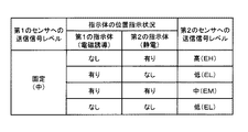
この第1の実施形態による位置検出装置における第1の指示体および第2の指示体の位置指示状況の遷移図を、図4に示す。そして、この第1の実施形態における第1の指示体および第2の指示体の位置指示状況と、第2のセンサに供給する送信信号の信号レベルの大きさとの対応表を、図5に示す。 FIG. 4 shows a transition diagram of the position indication status of the first indicator and the second indicator in the position detection apparatus according to the first embodiment. FIG. 5 shows a correspondence table between the position indication status of the first indicator and the second indicator and the magnitude of the signal level of the transmission signal supplied to the second sensor in the first embodiment. .
すなわち、図4の遷移図に示すように、第1の指示体および第2の指示体の位置指示状況は、第1の指示体と第2の指示体との両方が検出されていない非検出の状況501、第1の指示体のみが検出されている状況502、第2の指示体のみが検出されている状況503、第1の指示体と第2の指示体とが同時に検出されている同時検出の状況504、の4つの状況がある。そして、図4において矢印にて示すように、それぞれの状況間において遷移がある。
That is, as shown in the transition diagram of FIG. 4, the position indication status of the first indicator and the second indicator is non-detected in which both the first indicator and the second indicator are not detected.
なお、第1の指示体のみが検出されている状況502と、第2の指示体のみが検出されている状況503との間での遷移の矢印を破線にしたのは、これらの状況502と状況503との間の遷移は、非検出の状況501や、同時検出の状況504を経由して生じるのが通常であって、直接的に生じるのは、稀であると考えられることを考慮したものである。
It should be noted that the arrows indicating the transition between the
そして、以上のように遷移をする第1の指示体および第2の指示体の位置指示状況に対応して、第2のセンサ40への送信信号の信号レベルは、図5に示すように、制御される。
And, as shown in FIG. 5, the signal level of the transmission signal to the
すなわち、位置指示状況が、第1の指示体および第2の指示体の両方が検出されていない非検出の状況501あるいは第1の指示体のみが検出されている状況502では、第2のセンサ40に供給される送信信号の信号レベルは、低いレベルELに設定される。また、位置指示状況が、第2の指示体のみが検出されている状況503では、第2のセンサ40に供給される送信信号の信号レベルは、高レベルEHに設定される。更に、位置指示状況が、第1の指示体および第2の指示体の両方が同時に検出されている同時検出の状況504では、第2のセンサ40に供給される送信信号の信号レベルは、前記低レベルELと前記高レベルEHとの間の中レベルEMに設定される。
In other words, the position sensor is in the
なお、図5中の「第2のセンサへの送信信号レベル」の欄に記載された各信号レベルは、制御回路410からDC−DCコンバータ407を制御するための制御コードCP2により設定される。
Each signal level described in the column “transmission signal level to second sensor” in FIG. 5 is set by
ここで、図5において、送信信号の信号レベルのうち、高レベルEHは、静電容量方式の第2のセンサ40および位置検出回路400により、第2の指示体の位置指示の検出を、良好なS/Nの状態で行うことができるようにする信号レベルとされる。このときにDC−DCコンバータ407から送信信号増幅回路403に供給される電源電圧PW2は、例えば12〜24V(ボルト)程度に、その電圧値が制御される。
Here, in FIG. 5, the high level EH among the signal levels of the transmission signal is good for detecting the position indication of the second indicator by the capacitance type
また、送信信号の信号レベルのうち、中レベルEMは、静電容量方式の第2のセンサ40および位置検出回路400により、第2の指示体の位置指示の良好な検出を維持しつつ、電磁誘導方式の第1のセンサ20および位置検出回路200の位置検出信号のジッタの発生を軽減することができるようにする信号レベルとされる。このときにDC−DCコンバータ407から送信信号増幅回路403に供給される電源電圧PW2は、例えば3.3〜5V(ボルト)程度に、その電圧値が制御される。
In addition, among the signal levels of the transmission signal, the medium level EM is electromagnetic while maintaining good detection of the position indication of the second indicator by the
また、送信信号の信号レベルのうち、低レベルELは、静電容量方式の第2のセンサ40および位置検出回路400により、第2の指示体の位置指示の検出は可能であって、電磁誘導方式の第1のセンサ20および位置検出回路200の位置検出信号のジッタの発生を最小限に抑えることができる信号レベルとされる。このときに送信信号増幅回路403に供給する電源電圧PW2は、例えば3.3V(ボルト)程度に設定される。
Further, among the signal levels of the transmission signal, the low level EL can be detected by the electrostatic capacity type
なお、上述の例では、3つの信号レベルEH,EM,ELの大小関係は、EH>EM≧ELとされている。 In the above example, the magnitude relationship between the three signal levels EH, EM, EL is EH> EM ≧ EL.
また、この図5に示す例では、第1のセンサ20に位置検出回路200から供給される送信信号(電子ペン23へ電磁誘導信号を送るための交流信号)の信号レベルは、第1のセンサ20と位置検出回路200とにより、第1の指示体の位置指示を良好に行える固定値の信号レベルに設定されている。図5の例では、後述する図7、図11を用いた説明との関係から、第1のセンサ20への送信信号の信号レベルを中レベルとした。なお、後述するように、第1のセンサ20への送信信号の信号レベルを可変とすることもできる。
In the example shown in FIG. 5, the signal level of the transmission signal (the AC signal for sending the electromagnetic induction signal to the electronic pen 23) supplied from the position detection circuit 200 to the
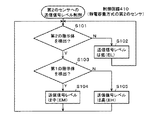
次に、位置検出回路400の制御回路410における、位置指示状況判別回路411の機能を含む送信信号の信号レベルの制御処理動作の例を、図6のフローチャートを参照して説明する。
Next, an example of the control processing operation of the signal level of the transmission signal including the function of the position indication
すなわち、制御回路410の位置指示状況判別回路411は、位置情報出力回路406からの第2のセンサ40の座標出力から生成した第2の指示体有無信号Dcと、位置検出回路200の制御回路210からの第1の指示体有無信号Dmとを監視し、先ず、第2の指示体有無信号Dcに基づき、第2の指示体が検出されている状況(状況503または状況504)であるか否か判別する(ステップS101)。
That is, the position indication
このステップS101において、第2の指示体が検出されてはいない状況(状況501または状況502)と判別されたときには、制御回路410は、制御コードCP2によりDC−DCコンバータ407を制御して、第2のセンサ40に供給される送信信号の信号レベルを、前述の低レベルELに設定する(ステップS102)。その後、制御回路410は、処理をステップS101に戻し、このステップS101以降の処理を繰り返す。
In this step S101, when it is determined that the second indicator is not detected (
また、ステップS101で、第2の指示体が検出されている状況(状況503または状況504)であると判別したときには、制御回路410の位置指示状況判別回路411は、第1の指示体有無信号Dmに基づき、第2の指示体のみでなく第1の指示体も検出されている状況(状況504)であるか否か判別する(ステップS103)。このステップS103で、第1の指示体と第2の指示体とが同時に検出されている状況(状況504)であると判別されたときには、制御回路410は、第2のセンサ40に供給する送信信号の信号レベルを、前述の中レベルEMとするような制御コードCP2を、D/A変換回路408を通じてDC−DCコンバータ407に出力する(ステップS104)。その後、制御回路410は、処理をステップS101に戻し、このステップS101以降の処理を繰り返す。
When it is determined in step S101 that the second indicator is being detected (
また、ステップS103で、第2の指示体は検出されているが、第1の指示体が検出されていない状況(状況503)であると判別されたときには、制御回路410は、送信信号レベルを、前述の高レベルEHとするような制御コードCP2を、D/A変換回路408を通じてDC−DCコンバータ407に出力する(ステップS105)。その後、制御回路410は、処理をステップS101に戻し、このステップS101以降の処理を繰り返す。
In step S103, when it is determined that the second indicator is detected but the first indicator is not detected (situation 503), the
なお、第2のセンサ40に供給される送信信号の信号レベルは、図4に示した状況の遷移が発生したときに、その状況の遷移後の信号レベルとなるように変更制御されるものであり、状況の遷移がないときには、その状況における信号レベルを維持するものであることは言うまでもない。
Note that the signal level of the transmission signal supplied to the
以上の処理ルーチンにより、この第1の実施形態では、図5に示したように、第1の指示体および第2の指示体の位置指示状況に応じて、第2のセンサ40への送信信号の信号レベルが制御される。これにより、第2のセンサに供給する送信信号による電磁誘導方式の位置検出回路200への悪影響を軽減しながら、第1の指示体および第2の指示体の指示位置の検出を良好に行うことができる。
By the above processing routine, in the first embodiment, as shown in FIG. 5, the transmission signal to the
すなわち、第2のセンサ40により第2の指示体が検出されていない状況のときには、第2のセンサ40に供給される送信信号の信号レベルは、低レベルELに設定され、第1のセンサ20および位置検出回路200における第1の指示体の位置検出信号におけるジッタが最小限となるように抑制される。
That is, when the
また、第2のセンサ40により第2の指示体が検出されている状況であっても、第1のセンサ20により第1の指示体が検出された状況のときには、第2の指示体のみが検出されるときの送信信号の信号レベルが高レベルEHよりも低い中レベルEMになるように、送信信号の信号レベルが制御されるので、第1のセンサ20および位置検出回路200における第1の指示体の位置検出信号におけるジッタが軽減される。
Even in a situation where the
そして、この実施形態では、第1のセンサ20で第1の指示体が検出されずに、第2の指示体が第2のセンサ40で検出された状況のときには、第2のセンサ40に供給される送信信号の信号レベルは、高レベルEHに設定されているので、表示デバイスからのノイズに拘わらず、指などの第2の指示体は、第2のセンサ40および位置検出回路400により、良好なS/Nの状態で検出することができる。
In this embodiment, when the first indicator is not detected by the
なお、この第1の実施形態では、電流ドライバ203から第1のセンサ20に供給される交流信号の信号レベルは固定値とされるので、DC−DCコンバータ211を設けずに、当該固定値の電源電圧が電流ドライバ203に供給されるように構成しても良い。
In the first embodiment, since the signal level of the AC signal supplied from the
[第2の実施形態]
上述の第1の実施形態では、電磁誘導方式の第1のセンサ20および位置検出回路200におけるジッタを軽減させるために、第2のセンサ40に供給される送信信号の信号レベルのみを制御するようにした。
[Second Embodiment]
In the first embodiment described above, only the signal level of the transmission signal supplied to the
しかし、第2のセンサ40に供給される送信信号の信号レベルを制御すると共に、第1の指示体を構成する位置指示器としての電子ペン23に第1のセンサ20から供給される電磁誘導信号の信号レベルを制御することで、より効果的に、静電容量方式の第2のセンサ40に供給される送信信号による電磁誘導方式の位置検出回路200への悪影響を軽減することができる。
However, while controlling the signal level of the transmission signal supplied to the
この第2の実施形態における位置検出装置のハードウエア構成は、上述した第1の実施形態と同様である。また、この第2の実施形態においても、位置検出回路400の制御回路410は、上述した第1の実施形態と同様にして、送信信号の信号レベルを制御するように構成される。
The hardware configuration of the position detection device in the second embodiment is the same as that in the first embodiment described above. Also in the second embodiment, the
そして、この第2の実施形態では、電子ペン23に第1のセンサ20から供給される電磁誘導信号の信号レベルを可変制御するために、第1のセンサ20の位置検出回路200の制御回路210は、第1のセンサ20に供給する送信信号(交流信号)の信号レベルを、固定値ではなく、可変制御する。すなわち、図示は省略するが、例えば図2に示した位置検出回路200の制御回路210も、位置指示状況判別回路を備えるようにする。そして、この制御回路210の位置指示状況判別回路には、位置検出回路400の制御回路410から、第2の指示体有無信号Dcを供給する。さらに、この制御回路210の位置指示状況判別回路には、当該制御回路210で生成した第1の指示体有無信号Dmを供給する。
In the second embodiment, the
制御回路210の位置指示状況判別回路は、第1の指示体有無信号Dmと第2の指示体有無信号Dcとから、第1の指示体および第2の指示体の位置指示状況を判別する。そして、制御回路210は、D/A変換回路212を通じてDC−DCコンバータ211に供給する制御コードP1を、その位置指示状況判別回路の判別結果に対応して可変制御することで、第1のセンサ20に供給される送信信号(交流信号)の信号レベルを制御する。その他の構成は、上述した第1の実施形態と同様とする。
The position indication status determination circuit of the
図7は、この第2の実施形態の場合における第1の指示体および第2の指示体の位置指示状況と、第2のセンサ40に供給される送信信号の信号レベルの大きさおよび第1のセンサ20に供給される送信信号(交流信号)の信号レベルの大きさを示すための対応表である。
FIG. 7 shows the position indication status of the first indicator and the second indicator in the case of the second embodiment, the magnitude of the signal level of the transmission signal supplied to the
この図7において、第1の指示体および第2の指示体の位置指示状況に対する、第2のセンサ40に供給される送信信号の信号レベルの大きさは、前述した図5と同様である。この図7と図5との相違点は、第1のセンサ20に供給される送信信号の信号レベルの大きさが、固定値ではなく、第1の指示体および第2の指示体の位置指示状況に対応して可変となっている点である。この例では、第1のセンサ20に供給される送信信号の信号レベルは、図5で設定した中レベルに加えて、当該中レベルよりも低い低レベル、および当該中レベルよりも高い高レベルを採用している。
In FIG. 7, the magnitude of the signal level of the transmission signal supplied to the
すなわち、位置指示状況が、第1の指示体が検出されない状況(第2の指示体のみが検出される状況503あるいは第1の指示体および第2の指示体の両方が検出されない非検出の状況501)では、第1のセンサ20に供給される送信信号の信号レベルは、第1の指示体を検出することが可能である低レベルに設定される。また、位置指示状況が、第1の指示体のみが検出される状況502では、第1のセンサ20に供給される送信信号の信号レベルは、第1の指示体を、第2のセンサ40へ送信信号が供給されることにより生じる悪影響を十分に避けて検出することができるような高レベルに設定される。更に、位置指示状況が、第1の指示体および第2の指示体の両方が同時に検出される同時検出の状況504では、第1のセンサ20に供給される送信信号の信号レベルは、前記低レベルと前記高レベルとの間の中間の中レベルに設定される。
That is, the position indication situation is a situation in which the first indicator is not detected (a
次に、位置検出回路200の制御回路210が、位置指示状況判別回路の機能を含む場合における送信信号の信号レベルの制御処理動作の例を、図8のフローチャートを参照して説明する。
Next, an example of the control processing operation of the signal level of the transmission signal when the
すなわち、制御回路210の位置指示状況判別回路は、第1の指示体有無信号Dmと第2の指示体有無信号Dcとを監視し、先ず、第1の指示体有無信号Dmに基づき、第1の指示体が検出されている状況(状況502または状況504)であるか否か判別する(ステップS201)。
That is, the position indication situation determination circuit of the
このステップS201において、第1の指示体が検出されてはいない状況(状況501または状況503)であると判別されたときには、制御回路210は、制御コードCP1によりDC−DCコンバータ211を制御して、第1のセンサ20に供給される送信信号の信号レベルを、前述の低レベルに設定する(ステップS202)。その後、制御回路210は、処理をステップS201に戻し、このステップS201以降の処理を繰り返す。
In step S201, when it is determined that the first indicator is not detected (
また、ステップS201で、第1の指示体が検出されている状況(状況502または状況504)であると判別したときには、制御回路210の位置指示状況判別回路は、第2の指示体有無信号Dcに基づき、第1の指示体に加えて第2の指示体が検出されている状況(状況504)であるか否か判別する(ステップS203)。
When it is determined in step S201 that the first indicator is being detected (
このステップS203で、第1の指示体に加えて第2の指示体が検出されている状況(状況504)であると判別されたときには、制御回路210は、制御コードCP1によりDC−DCコンバータ211を制御して、第1のセンサ20に供給される送信信号の信号レベルを、前述の中レベルEMに設定する(ステップS204)。その後、制御回路210は、処理をステップS201に戻し、このステップS201以降の処理を繰り返す。
When it is determined in step S203 that the second indicator is detected in addition to the first indicator (situation 504), the
また、ステップS203で、第1の指示体は検出されているが、第2の指示体は検出されていない状況(状況502)であると判別されたときには、制御回路210は、制御コードCP1によりDC−DCコンバータ211を制御して、第1のセンサ20に供給される送信信号の信号レベルを、前述の高レベルに設定する(ステップS205)。その後、制御回路210は、処理をステップS201に戻し、このステップS201以降の処理を繰り返す。
If it is determined in step S203 that the first indicator is detected but the second indicator is not detected (situation 502), the
なお、第1のセンサ20に供給される送信信号の信号レベルは、図4に示した状況の遷移が発生したときに、その状況の遷移後の信号レベルとなるように変更制御されるものであり、状況の遷移がないときには、その状況における送信信号の信号レベルを維持するものであることは言うまでもない。
Note that the signal level of the transmission signal supplied to the
上述した第2の実施形態によれば、上述した第1の実施形態と同様の効果が得られると共に、第2のセンサ40に供給される送信信号の信号レベルのみならず、第1のセンサ20に供給される送信信号の信号レベルが制御されることで、より効果的に、第2のセンサに供給される送信信号による電磁誘導方式の位置検出回路200への悪影響を軽減することができる。
According to the second embodiment described above, the same effects as those of the first embodiment described above can be obtained, and not only the signal level of the transmission signal supplied to the
すなわち、第2の実施形態においては、第1の指示体のみが検出される状況では、第2のセンサ40に供給される送信信号の信号レベルが低レベルに設定されると共に、第1のセンサ20に供給される送信信号(交流信号)の信号レベルが高レベルに設定されるので、第2のセンサに供給される送信信号により電磁誘導方式の位置検出回路200に生じる悪影響を、より軽減することができるという効果がある。
That is, in the second embodiment, in a situation where only the first indicator is detected, the signal level of the transmission signal supplied to the
また、第1のセンサ20に供給される送信信号(交流信号)の信号レベルが高レベルに設定されるので、第1のセンサ20および位置検出回路200は、第1の指示体を、よりS/Nの良好な状態で検出することができるという効果もある。
In addition, since the signal level of the transmission signal (AC signal) supplied to the
[第3の実施形態]
この第3の実施形態は、第2の実施形態の変形例である。すなわち、上述した第2の実施形態では、位置検出回路200の制御回路210と位置検出回路400の制御回路410のそれぞれが、位置指示状況判別回路の機能を備え、それぞれ、制御コードCP1、CP2を別個に生成するようにした。
[Third Embodiment]
The third embodiment is a modification of the second embodiment. That is, in the above-described second embodiment, each of the
これに対して、この第3の実施形態においては、位置検出回路200と位置検出回路400とは別個に位置指示状況判別回路を備える制御コード生成回路を設けて、制御回路210と制御回路410の処理負担を軽減するようにする。
On the other hand, in the third embodiment, a control code generation circuit including a position indication situation determination circuit is provided separately from the position detection circuit 200 and the position detection circuit 400, and the
図9は、この第3の実施形態の電子機器10の位置検出回路のハードウエア構成例の要部を示すものである。この要部に示す部分以外は、上述した第1の実施形態および第2の実施形態と同様の構成とされる。
FIG. 9 shows a main part of a hardware configuration example of the position detection circuit of the
すなわち、図9に示すように、第3の実施形態における位置検出回路200の制御回路210Aは、第1の指示体有無信号Dmを生成する機能は有するが、位置指示状況判別回路の機能および制御コードCP1を生成する機能は有しない。また、第3の実施形態における位置検出回路400の制御回路410Aは、第2の指示体有無信号Dcを生成する機能は有するが、位置指示状況判別回路の機能および制御コードCP2を生成する機能は有しない。
That is, as shown in FIG. 9, the
そして、第3の実施形態の位置検出装置においては、制御コード発生回路600が設けられる。この制御コード発生回路600は、位置指示状況判別回路601と、制御コード発生回路602とを備える。
In the position detection apparatus of the third embodiment, a control
位置指示状況判別回路601には、位置検出回路200の制御回路210Aから、第1の指示体有無信号Dmが供給されると共に、位置検出回路400の制御回路410Aから、第2の指示体有無信号Dcが供給される。位置指示状況判別回路601は、これら第1の指示体有無信号Dmおよび第2の指示体有無信号Dcから、第1の指示体と第2の指示体の、電子機器10の位置検出装置における位置指示状況を判別し、その判別結果を制御コード発生回路602に供給する。
The position indicator
制御コード発生回路602は、位置指示状況判別回路601からの第1の指示体と第2の指示体の位置指示状況の判別結果に対応して、制御コードCP1および制御コードCP2を生成する。そして、制御コード発生回路602は、制御コードCP1をD/A変換回路212を通じて、DC−DCコンバータ211の制御端FBに供給して、第1のセンサ20に供給する送信信号の信号レベルを制御する。また、制御コード発生回路602は、制御コードCP2をD/A変換回路408を通じてDC−DCコンバータ407に供給して、第2のセンサ40に供給する送信信号の信号レベルを制御する。
The control
この制御コード生成回路600における処理動作例のフローチャートを図10に示す。
FIG. 10 shows a flowchart of an example of processing operation in the control
制御コード生成回路600の位置指示状況判別回路601は、第1の指示体有無信号Dmと第2の指示体有無信号Dcとを監視し、第1の指示体と第2の指示体とが検出されていない状況501であるか否か判別する(ステップS301)。このステップS301で、状況501であると判別されたときには、制御コード生成回路602は、第1のセンサ20に供給する送信信号の信号レベルを低レベルとするように、制御コードCP1を生成してD/A変換回路212に出力すると共に、第2のセンサ40に供給する送信信号の信号レベルを低レベルELとするように、制御コードCP2を生成してD/A変換回路408に出力する(ステップS302)。そして、制御コード生成回路600は、処理をステップS301に戻し、このステップS301以降の処理を繰り返す。
The position indication
ステップS301で、第1の指示体も第2の指示体も検出されない非検出状況501ではないと判別したときには、位置指示状況判別回路601は、第1の指示体と第2の指示体とが同時に検出される同時検出504の状況であるか否か判別する(ステップS303)。このステップS303で、同時検出の状況504であると判別されたときには、制御コード生成回路602は、第1のセンサ20に供給する送信信号の信号レベルを中レベルとするように、制御コードCP1を生成してD/A変換回路212に出力すると共に、第2のセンサ40に供給する送信信号の信号レベルを中レベルEMとするように、制御コードCP2を生成してD/A変換回路408に出力する(ステップS304)。そして、制御コード生成回路600は、処理をステップS301に戻し、このステップS301以降の処理を繰り返す。
If it is determined in step S301 that the first indicator and the second indicator are not detected in the
ステップS303で、同時検出の状況504ではないと判別したときには、位置指示状況判別回路601は、第1の指示体のみが検出されている状況502であるか否か判別する(ステップS305)。このステップS305で、第1の指示体のみが検出されている状況502であると判別されたときには、制御コード生成回路602は、第1のセンサ20に供給する送信信号の信号レベルを高レベルとするように、制御コードCP1を生成してD/A変換回路212に出力すると共に、第2のセンサ40に供給する送信信号の信号レベルを低レベルELとするように、制御コードCP2を生成してD/A変換回路408に出力する(ステップS306)。そして、制御コード生成回路600は、処理をステップS301に戻し、このステップS301以降の処理を繰り返す。
When it is determined in step S303 that the situation is not the
また、ステップS305で、第1の指示体のみが検出されている状況502ではなく、第2の指示体のみが検出されている状況503であると判別されたときには、制御コード生成回路602は、第1のセンサ20に供給する送信信号の信号レベルを低レベルとするように、制御コードCP1を生成してD/A変換回路212に出力すると共に、第2のセンサ40に供給する送信信号の信号レベルを高レベルEHとするように、制御コードCP2を生成してD/A変換回路408に出力する(ステップS307)。そして、制御コード生成回路600は、処理をステップS301に戻し、このステップS301以降の処理を繰り返す。
When it is determined in step S305 that the situation is not the
この第3の実施形態においても、第2の実施形態と同様の作用効果が得られる。 In the third embodiment, the same function and effect as in the second embodiment can be obtained.
なお、上述の第3の実施形態においては、一つの制御コード発生回路602で、制御コードCP1と制御コードCP2とを発生させるようにした。しかし、制御コード発生回路602の代わりに、制御コードCP1を発生する制御コード発生回路と、制御コードCP2を発生する制御コード発生回路とを別々に備えるようにしてもよい。その場合には、制御コードCP1を発生する制御コード発生回路では、位置指示状況判別回路601からの判別結果に対応して、前述した図8に示した処理を実行して制御コードCP1を発生し、また、制御コードCP2を発生する制御コード発生回路では、位置指示状況判別回路601からの判別結果に対応して、前述した図6に示した処理を実行して制御コードCP2を発生するようにすることができる。
In the third embodiment described above, the control code CP1 and the control code CP2 are generated by one control
[第4の実施形態]
上述の第1の実施形態では、電磁誘導方式の第1のセンサ20および位置検出回路200におけるジッタ性能の悪化を軽減させるために、第2のセンサ40に供給する送信信号の信号レベルを低くするように制御するようにした。
[Fourth Embodiment]
In the first embodiment described above, the signal level of the transmission signal supplied to the
しかし、第2のセンサ40に供給する送信信号の信号レベルを低くする代わりに、第1のセンサ20から第1の指示体を構成する位置指示器としての電子ペンに供給する電磁信号のレベルを高くするように制御することによっても、第2のセンサに供給する送信信号による第1のセンサおよび位置検出回路200での第1の指示体の検出処理への悪影響を軽減するという、所期の目的を達成することができる。
However, instead of lowering the signal level of the transmission signal supplied to the
第4の実施形態は、そのように構成した位置検出装置の場合である。この第4の実施形態においても、ハードウエア構成例は、図1および図2に示したものと同様である。ただし、この第4の実施形態においては、図2において、制御回路210は、位置指示状況判別回路を備えると共に、第1の指示体有無信号をその位置指示状況判別回路に供給するようにする。そして、位置検出回路400の制御回路410は、この位置検出回路200の制御回路210の位置指示状況判別回路に、第2の指示体有無信号Dcを供給するようにする。この第4の実施形態では、位置検出回路400の制御回路410は、位置指示状況判別回路411の機能は備えない。
The fourth embodiment is a case of the position detection device configured as described above. Also in the fourth embodiment, the hardware configuration example is the same as that shown in FIGS. However, in the fourth embodiment, in FIG. 2, the
制御回路210の位置指示状況判別回路は、第1の指示体有無信号Dmと第2の指示体有無信号Dcとから、第1の指示体および第2の指示体により位置検出装置における位置指示状況を判別する。そして、制御回路210は、この位置指示状況判別回路の判別結果に対応して、制御コードCP1を生成するようにする。
The position indication status determination circuit of the
図11は、この第4の実施形態の場合における第1の指示体および第2の指示体の位置指示状況と、第2のセンサ40に供給する送信信号の信号レベルの大きさおよび第1のセンサ20に供給する送信信号の信号レベルの大きさを示すための対応表である。この図11の例においては、図5および図7と同様に、送信信号の信号レベルを、低、中、高の、3段階に制御する場合を説明する。
FIG. 11 shows the position indication status of the first indicator and the second indicator in the case of the fourth embodiment, the magnitude of the signal level of the transmission signal supplied to the
すなわち、この第4の実施形態においては、図11に示すように、第2のセンサ40に供給される送信信号は、表示デバイス30からのノイズに拘わらず、第2の指示体をS/N良く検出することができる中レベルに固定するようにする。
That is, in the fourth embodiment, as shown in FIG. 11, the transmission signal supplied to the
一方、第1のセンサ20から第1の指示体を構成する位置指示器としての電子ペン23に供給する電磁信号の信号レベルを制御するために、この第4の実施形態では、第1のセンサに供給される送信信号の信号レベルを、図11に示すように制御する。すなわち、第1のセンサに供給される送信信号の信号レベルを、第1の指示体のみが検出されていて、第2の指示体が検出されていない状況では、高レベルに設定し、また、第1の指示体に加えて第2の指示体が検出されている状況では、中レベルに設定するようにする。更に、第1の指示体が検出されていない状況では、第2の指示体が検出されているか否かにかかわらず、第1のセンサに供給される送信信号の信号レベルを、低レベルに設定するようにする。
On the other hand, in order to control the signal level of the electromagnetic signal supplied from the
この第4の実施形態においても、静電容量方式の第2のセンサ40に供給される送信信号による電磁誘導方式の位置検出回路200への悪影響を軽減することもできる。
Also in the fourth embodiment, it is possible to reduce the adverse effect on the electromagnetic induction type position detection circuit 200 due to the transmission signal supplied to the capacitive
なお、上述の第1の実施形態の位置検出装置が適用された電子機器10では、表示デバイス30が存在し、この表示デバイス30からのノイズに拘わらず、静電容量方式の第2のセンサ40および位置検出回路400の位置検出出力をS/N良く、検出できるようにするため、第2のセンサ40に供給する送信信号の信号レベルを、中レベルに設定するようにした。
In the
しかし、表示デバイス等のノイズ源が存在せずに、第1のセンサ20と第2のセンサ40とが、例えば重畳して配置される電子機器においては、第2のセンサ40に、第1の実施形態の場合のような中レベルの送信信号を供給する必要はない。したがって、その場合には、図11における第2のセンサへの送信信号の信号レベルは、低レベル、好ましくは中レベルEMとするようにしても良い。
However, in an electronic device in which the
[その他の実施形態または変形例]
以上説明した電磁誘導方式の第1のセンサは、X軸方向に配列されたループコイル群と、Y軸方向に配列されたループコイル群の一方を、電子ペンに電磁誘導信号を供給するコイルとして用いるようにしたが、電磁誘導方式の第1のセンサは、このようなタイプのものに限られるものではない。
[Other Embodiments or Modifications]
The first sensor of the electromagnetic induction method described above uses one of the loop coil group arranged in the X-axis direction and the loop coil group arranged in the Y-axis direction as a coil that supplies an electromagnetic induction signal to the electronic pen. Although used, the first electromagnetic induction type sensor is not limited to this type.
例えば、図12に示すような電磁誘導方式の第1のセンサ80を用いることもできる。すなわち、この図12の例においては、検出コイル基板81の一方の面上には、X軸方向およびY軸方向に配列されたグリッド形状の検出用ループコイル82Xおよび82Yを備える。そして、この検出コイル基板81の一方の面、あるいは他方の面の周部に、第1の指示体を構成する位置指示器(電子ペン)84に電磁誘導信号を供給する駆動コイルを、図12において点線で示すように、周辺励磁コイル83として配置するようにする。
For example, an electromagnetic induction type first sensor 80 as shown in FIG. 12 may be used. That is, in the example of FIG. 12, on one surface of the detection coil substrate 81, grid-shaped
位置検出回路800は、この周辺励磁コイル83に所定の周波数信号を供給する。これにより、周辺励磁コイル83に電磁誘導信号が発生し、第1の指示体としての位置指示器(電子ペン)84の共振回路841に、その電磁誘導信号に応じたエネルギーが蓄えられる。そして、位置指示器84は、その共振回路841に蓄えた磁界エネルギーを、第1のセンサ80の検出コイル基板81に供給する。
The
位置検出回路800は、検出用ループコイル82X、82Yで受信された信号に基づいて位置指示器84が指示する位置を検出する。すなわち、位置指示器84の共振回路841による磁界に応じて検出用ループコイル82X、82Yには誘導電流が生じる。位置検出回路800は、検出用ループコイル82X、82Yを切り替えながら、誘導電流が生じた検出用ループコイル82X、82Yの位置を判定し、その判定結果から位置指示器84が指示する位置を算出して出力する。
The
この図12の電磁誘導方式の第1のセンサの場合には、周辺励磁コイル83に供給される所定の周波数の信号の信号レベルが、位置検出回路の制御回路からの制御コードにより制御されるものである。 In the case of the first electromagnetic induction type sensor of FIG. 12, the signal level of a signal of a predetermined frequency supplied to the peripheral excitation coil 83 is controlled by a control code from the control circuit of the position detection circuit. It is.
また、以上説明した例では、電磁誘導方式の第1のセンサと組み合わされる位置指示器は、共振回路(電磁結合回路)を備え、第1のセンサからの電磁誘導信号の供給を受けて、その誘導磁界に応じたエネルギーを共振回路に蓄え、その蓄えたエネルギーを第1のセンサに供給するようにした。 Moreover, in the example demonstrated above, the position indicator combined with the 1st sensor of an electromagnetic induction system is provided with the resonance circuit (electromagnetic coupling circuit), receives the supply of the electromagnetic induction signal from the 1st sensor, Energy corresponding to the induced magnetic field is stored in the resonance circuit, and the stored energy is supplied to the first sensor.
しかし、位置指示器が、駆動電源としてバッテリーを備えると共に、第1のセンサに電磁誘導信号を供給するための発振器を備える構成を有している場合には、第1のセンサからは、位置指示器に、電磁誘導信号を供給する必要はない。この発明の位置検出装置における電磁誘導方式の第1のセンサは、このような位置指示器に電磁誘導信号を供給しないタイプの電磁誘導方式のセンサであっても良い。 However, when the position indicator has a configuration including a battery as a driving power source and an oscillator for supplying an electromagnetic induction signal to the first sensor, the position indication from the first sensor. There is no need to supply an electromagnetic induction signal to the vessel. The first electromagnetic induction type sensor in the position detection device of the present invention may be an electromagnetic induction type sensor that does not supply an electromagnetic induction signal to such a position indicator.
また、上述の実施形態では、第1のセンサと第2のセンサとの間に表示デバイスが設けられる構成であったが、この発明による位置検出装置は、表示デバイスを備えずに、第1のセンサと第2のセンサとを備える構成であってもよいことは言うまでもない。 In the above-described embodiment, the display device is provided between the first sensor and the second sensor. However, the position detection device according to the present invention does not include the display device. Needless to say, the configuration may include a sensor and a second sensor.
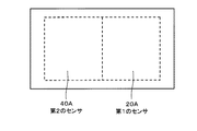
また、上述の実施形態では、第1のセンサと第2のセンサとは、互いの検出領域が重畳されるように配置されていたが、このような重畳配置に限らず、第1のセンサと第2のセンサのそれぞれの検出領域が一部重畳して配置される場合や、第1センサと第2のセンサとが近接して配置されている場合にも、この発明は適用可能である。すなわち、例えば図13に示すように、第1のセンサ20Aと第2のセンサ40Aとが、水平方向に近接して配置された場合においても、その近接する領域においては、第2のセンサに供給される送信信号による悪影響が、第1のセンサの位置検出出力に現れるおそれがあるので、この図13の例のような配置であっても、この発明は適用可能である。
Further, in the above-described embodiment, the first sensor and the second sensor are arranged so that the detection areas of the first sensor and the second sensor are superimposed. However, the first sensor and the second sensor are not limited to such a superimposed arrangement. The present invention can also be applied when the detection areas of the second sensors are partially overlapped or when the first sensor and the second sensor are arranged close to each other. That is, for example, as shown in FIG. 13, even when the
なお、上述の実施形態では、第1の指示体および第2の指示体により指示された位置の座標値が算出されたか否かにより、第1の指示体および第2の指示体が、第1のセンサ20および第2のセンサ40で検出されているかどうかを示す指示体有無信号DcおよびDmを生成し、位置指示状況判別回路では、この指示体有無信号DcおよびDmに基づいて、位置指示状況を判別するようにした。しかし、第1の指示体および第2の指示体が、第1のセンサ20および第2のセンサ40で検出されているかどうかは、第1のセンサ20および第2のセンサ40からの出力信号を監視することによって判別することが可能である。したがって、位置指示状況判別回路は、上述のような座標値が算出されたか否かに基づいて生成された指示体有無信号DcおよびDmではなく、第1のセンサ20および第2のセンサ40からの出力信号に基づいて生成された指示体有無信号から、位置指示状況を判別するようにしても良い。
In the above-described embodiment, the first indicator and the second indicator are the first indicator depending on whether or not the coordinate value of the position indicated by the first indicator and the second indicator is calculated. The indicator indicating presence / absence signals Dc and Dm indicating whether the
また、上述の説明では、第1の指示体および第2の指示体についての指示体有無信号を生成し、位置指示状況判別回路では、その指示体有無信号に基づいて、位置指示状況を判別するようにした。しかし、指示体有無信号を生成することなく、位置指示状況判別回路で、第1のセンサ20および第2のセンサ40についての位置検出回路の座標出力に基づいて、あるいは、第1のセンサ20および第2のセンサ40からのセンサ出力に基づいて、位置指示状況を判別するようにしても良い。
In the above description, the indicator presence / absence signals for the first indicator and the second indicator are generated, and the position indication status determination circuit determines the position indication status based on the indicator presence / absence signal. I did it. However, without generating a pointer existence signal, at a position indication state determination circuit, based on the coordinate output of the position detection circuit for the
なお、電磁誘導方式以外の検出方式の第2のセンサとしては、上述の実施形態では、静電容量方式のセンサを例にしたが、この第2のセンサとしては、静電容量方式のセンサに限られるものではなく、第2のセンサに送信信号が供給され、その送信信号が、電磁誘導方式の第1のセンサおよび位置検出回路の検出結果に影響を与える場合の全てに、この発明は適用可能である。 As the second sensor of the detection method other than the electromagnetic induction method, in the above-described embodiment, the capacitive sensor is taken as an example. However, as the second sensor, a capacitive sensor is used. The present invention is not limited to this, and the present invention is applied to all cases where a transmission signal is supplied to the second sensor and the transmission signal affects the detection results of the electromagnetic induction first sensor and the position detection circuit. Is possible.
また、この発明が適用される電子機器は、上述したパッド型端末などに限られるものではなく、第1のセンサと第2のセンサとを備え、同時に第1の指示体と第2の指示体の検出が可能となる電子機器(例えばタブレット型パソコンや液晶タブレット等)であれば、どのようなものであっても良い。 The electronic device to which the present invention is applied is not limited to the above-described pad-type terminal and the like, and includes a first sensor and a second sensor, and at the same time, a first indicator and a second indicator. As long as it is an electronic device (for example, a tablet-type personal computer or a liquid crystal tablet) that can detect this, any device may be used.
20…第1のセンサ、40…第2のセンサ、200…電磁誘導方式の位置検出回路(第1の位置検出回路)、210…制御回路、400…静電容量方式の位置検出回路(第2の位置検出回路)、410…制御回路、411,601…位置指示状況判別回路
DESCRIPTION OF
Claims (7)
前記第2のセンサに前記第2の指示体による位置指示を検出するための送信信号を供給する信号供給回路と、
前記第1の指示体による位置指示に対応して前記第1のセンサから出力される信号と、前記第2の指示体による位置指示に対応して前記第2のセンサから出力される信号が供給されて、前記第1の指示体と前記第2の指示体とによる位置指示状況を判別する位置指示状況判別回路と、
前記位置指示状況判別回路による前記位置指示状況の判別結果に対応して、前記信号供給回路から前記第2のセンサに供給される前記送信信号の信号レベルを制御する信号レベル制御回路と、
を備えており、
前記位置指示状況判別回路によって判別された前記位置指示状況に基づいて、前記第1の指示体と前記第2の指示体が互いに非同時的位置指示の状況から、前記第1の指示体と前記第2の指示体が同時的位置指示の状況に遷移した際には、前記信号レベル制御回路によって、前記第1の指示体と前記第2の指示体が互いに非同時的位置指示の状況において前記第2のセンサに供給される送信信号の信号レベルよりも信号レベルが異なる送信信号を前記第2のセンサに供給して前記第2の指示体による位置指示を検出するようにした
ことを特徴とする位置検出装置。 A first sensor for detecting a position indication by a first indicator by an electromagnetic induction method, and a second instruction by a detection method other than the electromagnetic induction method, and disposed in proximity to the first sensor A second sensor for detecting a position indication by a body, and a position detection device capable of simultaneously detecting a position indication by the first indicator and the second indicator,
A signal supply circuit for supplying a transmission signal for detecting a position indication by the second indicator to the second sensor;
A signal output from the first sensor in response to a position instruction by the first indicator and a signal output from the second sensor in response to a position instruction by the second indicator are supplied. A position indicating situation determination circuit for determining a position indicating situation by the first indicator and the second indicator;
A signal level control circuit for controlling a signal level of the transmission signal supplied from the signal supply circuit to the second sensor in response to a determination result of the position indication situation by the position indication situation discrimination circuit;
With
Based on the position indication situation determined by the position indication situation determination circuit, the first indicator and the second indicator are determined from the situation where the first indicator and the second indicator are not simultaneous with each other. When the second indicator transitions to the simultaneous position indication situation, the signal level control circuit causes the first indicator and the second indicator to move in the non-simultaneous position indication situation. A transmission signal having a signal level different from the signal level of the transmission signal supplied to the second sensor is supplied to the second sensor to detect a position indication by the second indicator. Position detector.
ことを特徴とする請求項1に記載の位置検出装置。 The situation in which the first indicator and the second indicator are in a non-simultaneous position indication refers to the situation in which the second indicator is in a position indication state, and from the situation, the first indicator and the second indicator When the second indicator transitions to a simultaneous position indication situation, the signal level control circuit causes a transmission signal supplied to the second sensor to be sent to the second sensor in the position indication situation. 2. The position according to claim 1, wherein a transmission signal whose signal level is set lower than a signal level is supplied to the second sensor to detect a position indication by the second indicator. Detection device.
ことを特徴とする請求項1に記載の位置検出装置。 The situation in which the first indicator and the second indicator are in a non-simultaneous position indication is a situation in which the first indicator is in a position indication state, and from the situation, the first indicator and the second indicator When the second indicator transitions to a simultaneous position indication situation, the signal level control circuit causes a transmission signal supplied to the second sensor in the position indication situation of the first indicator. 2. The position according to claim 1, wherein a transmission signal whose signal level is set higher than a signal level is supplied to the second sensor to detect a position indication by the second indicator. Detection device.
前記信号レベル制御回路は、前記位置指示状況判別回路による前記位置指示状況の判別結果に対応して、前記電磁誘導信号供給回路から第1の指示体に供給される前記電磁誘導信号の信号レベルを制御するようにした
ことを特徴とする請求項1に記載の位置検出装置。 The first indicator has a coil, and further includes an electromagnetic induction signal supply circuit for supplying an electromagnetic induction signal to the coil wirelessly,
The signal level control circuit determines a signal level of the electromagnetic induction signal supplied from the electromagnetic induction signal supply circuit to the first indicator in response to the determination result of the position indication situation by the position indication situation discrimination circuit. The position detection device according to claim 1, wherein the position detection device is controlled.
ことを特徴とする請求項4に記載の位置検出装置。 The position detection device according to claim 4, wherein the electromagnetic induction signal supply circuit includes a coil for supplying the electromagnetic induction signal to a coil included in the first indicator.
ことを特徴とする請求項1に記載の位置検出装置。 The position detection apparatus according to claim 1, wherein the first sensor and the second sensor are arranged so as to overlap each other.
前記第2のセンサに前記第2の指示体による位置指示を検出するための送信信号を供給する信号供給ステップと、
前記第1の指示体による位置指示に対応して前記第1のセンサから出力される信号と、前記第2の指示体による位置指示に対応して前記第2のセンサから出力される信号が供給されて、前記第1の指示体と前記第2の指示体による位置指示状況を判別する位置指示状況判別ステップと、
前記位置指示状況判別ステップによる前記位置指示状況の判別結果に対応して、前記信号供給ステップによって前記第2のセンサに供給される前記送信信号の信号レベルを制御する信号レベル制御ステップと、を備えており、
前記位置指示状況判別ステップによって判別された前記位置指示状況に基づいて、前記第1の指示体と前記第2の指示体が互いに非同時的位置指示の状況から、前記第1の指示体と前記第2の指示体が同時的位置指示の状況に遷移した際には、前記信号レベル制御ステップによって、前記第1の指示体と前記第2の指示体が互いに非同時的位置指示の状況において前記第2のセンサに供給される送信信号の信号レベルよりも信号レベルが異なる送信信号を前記第2のセンサに供給して前記第2の指示体による位置指示を検出するようにした
ことを特徴とする位置検出方法。 A first sensor for detecting a position indication by a first indicator by an electromagnetic induction method, and a second instruction by a detection method other than the electromagnetic induction method, and disposed in proximity to the first sensor A second sensor for detecting a position indication by a body, and a position detection method capable of simultaneously detecting a position indication by the first indicator and the second indicator,
A signal supply step of supplying a transmission signal for detecting a position indication by the second indicator to the second sensor;
A signal output from the first sensor in response to a position instruction by the first indicator and a signal output from the second sensor in response to a position instruction by the second indicator are supplied. A position indicating situation determining step for determining a position indicating situation by the first indicator and the second indicator;
A signal level control step for controlling the signal level of the transmission signal supplied to the second sensor by the signal supply step in response to the determination result of the position indication status by the position indication status determination step. And
Based on the position indication situation determined in the position indication situation determination step, the first indicator and the second indicator are not synchronized with each other. When the second indicator transitions to the simultaneous position indication situation, the signal level control step causes the first indicator and the second indicator to move in the non-simultaneous position indication situation. A transmission signal having a signal level different from the signal level of the transmission signal supplied to the second sensor is supplied to the second sensor to detect a position indication by the second indicator. Position detection method.
Priority Applications (8)
| Application Number | Priority Date | Filing Date | Title |
|---|---|---|---|
| JP2011264871A JP5848589B2 (en) | 2011-12-02 | 2011-12-02 | Position detection apparatus and position detection method |
| IL222694A IL222694A (en) | 2011-12-02 | 2012-10-25 | Position detector and position detection method |
| US13/665,502 US8766624B2 (en) | 2011-12-02 | 2012-10-31 | Position detector and position detection method |
| TW101140298A TWI579738B (en) | 2011-12-02 | 2012-10-31 | Position detector and position detection method |
| CN2012206025738U CN203133780U (en) | 2011-12-02 | 2012-11-14 | Position detecting device |
| CN201210458922.8A CN103135838B (en) | 2011-12-02 | 2012-11-14 | Position detecting device and method for detecting position |
| KR1020120135528A KR20130062229A (en) | 2011-12-02 | 2012-11-27 | Position detector and position detection method |
| EP12195069.5A EP2600230B1 (en) | 2011-12-02 | 2012-11-30 | Position detector and position detection method |
Applications Claiming Priority (1)
| Application Number | Priority Date | Filing Date | Title |
|---|---|---|---|
| JP2011264871A JP5848589B2 (en) | 2011-12-02 | 2011-12-02 | Position detection apparatus and position detection method |
Publications (3)
| Publication Number | Publication Date |
|---|---|
| JP2013117846A JP2013117846A (en) | 2013-06-13 |
| JP2013117846A5 JP2013117846A5 (en) | 2015-01-22 |
| JP5848589B2 true JP5848589B2 (en) | 2016-01-27 |
Family
ID=47325903
Family Applications (1)
| Application Number | Title | Priority Date | Filing Date |
|---|---|---|---|
| JP2011264871A Active JP5848589B2 (en) | 2011-12-02 | 2011-12-02 | Position detection apparatus and position detection method |
Country Status (7)
| Country | Link |
|---|---|
| US (1) | US8766624B2 (en) |
| EP (1) | EP2600230B1 (en) |
| JP (1) | JP5848589B2 (en) |
| KR (1) | KR20130062229A (en) |
| CN (2) | CN203133780U (en) |
| IL (1) | IL222694A (en) |
| TW (1) | TWI579738B (en) |
Families Citing this family (9)
| Publication number | Priority date | Publication date | Assignee | Title |
|---|---|---|---|---|
| JP5848589B2 (en) * | 2011-12-02 | 2016-01-27 | 株式会社ワコム | Position detection apparatus and position detection method |
| JP6249486B2 (en) * | 2013-08-19 | 2017-12-20 | 株式会社ワコム | Drawing device |
| US9158427B1 (en) * | 2014-03-25 | 2015-10-13 | Netio Technologies Co., Ltd. | Electromagnetic sensing touch screen |
| JPWO2015182222A1 (en) * | 2014-05-27 | 2017-06-01 | 株式会社ワコム | Indicator detection apparatus and signal processing method thereof |
| TWI544391B (en) * | 2014-06-09 | 2016-08-01 | 義隆電子股份有限公司 | Capacitive touch panel having approaching sensing function and scan method thereof |
| JP6923995B2 (en) * | 2014-09-24 | 2021-08-25 | 任天堂株式会社 | Information processing system, information processing device, information processing program, and information processing method |
| TWI599933B (en) * | 2016-09-21 | 2017-09-21 | 奕力科技股份有限公司 | Touch sensing apparatus |
| CN111316212A (en) | 2018-02-13 | 2020-06-19 | 株式会社和冠 | Position detection device and position detection method based on electromagnetic induction coupling and electrostatic coupling |
| JP2020187427A (en) | 2019-05-10 | 2020-11-19 | 株式会社ジャパンディスプレイ | Sensor device |
Family Cites Families (20)
| Publication number | Priority date | Publication date | Assignee | Title |
|---|---|---|---|---|
| JPH09138730A (en) * | 1995-11-14 | 1997-05-27 | Sharp Corp | Information input processor |
| US6498590B1 (en) | 2001-05-24 | 2002-12-24 | Mitsubishi Electric Research Laboratories, Inc. | Multi-user touch surface |
| JP4126610B2 (en) | 2002-12-26 | 2008-07-30 | エルジー ディスプレイ カンパニー リミテッド | Liquid crystal display |
| DE202004021638U1 (en) * | 2003-02-10 | 2009-12-31 | N-Trig Ltd. | Touch detection for a digitizer |
| US20050052427A1 (en) * | 2003-09-10 | 2005-03-10 | Wu Michael Chi Hung | Hand gesture interaction with touch surface |
| WO2007129085A2 (en) * | 2006-05-09 | 2007-11-15 | Sensopad Limited | Navigation arrangement for an electronic device |
| JP4915232B2 (en) * | 2006-12-19 | 2012-04-11 | ソニー株式会社 | Coordinate input device and coordinate input system |
| JP5094376B2 (en) * | 2007-12-28 | 2012-12-12 | 株式会社ワコム | Position detection device |
| CN101551713A (en) * | 2008-03-31 | 2009-10-07 | 太瀚科技股份有限公司 | Pointer input device with double input modes |
| JP2009265759A (en) * | 2008-04-22 | 2009-11-12 | Wacom Co Ltd | Position detection device and component for position detection |
| EP2300899A4 (en) * | 2008-05-14 | 2012-11-07 | 3M Innovative Properties Co | Systems and methods for assessing locations of multiple touch inputs |
| CN201247458Y (en) * | 2008-09-04 | 2009-05-27 | 汉王科技股份有限公司 | Display device with double-mode input function |
| CN101667085A (en) * | 2008-09-04 | 2010-03-10 | 汉王科技股份有限公司 | Dual-mode input device |
| JP2011003034A (en) | 2009-06-18 | 2011-01-06 | Toshiba Corp | Power system monitoring controller, and control method and control program of the same |
| JP5427070B2 (en) * | 2010-03-05 | 2014-02-26 | 株式会社ワコム | Position detection device |
| TWI470530B (en) * | 2011-02-01 | 2015-01-21 | Hungta Liu | Touch sensors and touch display apparatus and driving method thereof |
| TWI437474B (en) * | 2010-12-16 | 2014-05-11 | Hongda Liu | Dual-modes touch sensor and touch display and driving method thereof |
| TW201250530A (en) * | 2011-06-07 | 2012-12-16 | Hannstar Display Corp | Integrated touch panel structure and manufacturing method thereof |
| TWI447610B (en) * | 2011-11-25 | 2014-08-01 | Spatial location detection method and system of subject matter | |
| JP5848589B2 (en) * | 2011-12-02 | 2016-01-27 | 株式会社ワコム | Position detection apparatus and position detection method |
-
2011
- 2011-12-02 JP JP2011264871A patent/JP5848589B2/en active Active
-
2012
- 2012-10-25 IL IL222694A patent/IL222694A/en active IP Right Grant
- 2012-10-31 US US13/665,502 patent/US8766624B2/en active Active
- 2012-10-31 TW TW101140298A patent/TWI579738B/en active
- 2012-11-14 CN CN2012206025738U patent/CN203133780U/en not_active Withdrawn - After Issue
- 2012-11-14 CN CN201210458922.8A patent/CN103135838B/en active Active
- 2012-11-27 KR KR1020120135528A patent/KR20130062229A/en not_active Application Discontinuation
- 2012-11-30 EP EP12195069.5A patent/EP2600230B1/en active Active
Also Published As
| Publication number | Publication date |
|---|---|
| TWI579738B (en) | 2017-04-21 |
| EP2600230A3 (en) | 2015-01-21 |
| US8766624B2 (en) | 2014-07-01 |
| EP2600230B1 (en) | 2018-10-03 |
| IL222694A (en) | 2016-12-29 |
| CN103135838B (en) | 2017-09-12 |
| EP2600230A2 (en) | 2013-06-05 |
| CN103135838A (en) | 2013-06-05 |
| KR20130062229A (en) | 2013-06-12 |
| US20130141085A1 (en) | 2013-06-06 |
| JP2013117846A (en) | 2013-06-13 |
| CN203133780U (en) | 2013-08-14 |
| TW201342146A (en) | 2013-10-16 |
Similar Documents
| Publication | Publication Date | Title |
|---|---|---|
| JP5848589B2 (en) | Position detection apparatus and position detection method | |
| JP6156948B2 (en) | Demodulation changes to prevent interference | |
| JP5427070B2 (en) | Position detection device | |
| US10175791B2 (en) | Display device with integrated touch screen | |
| US9817512B1 (en) | Driving chip, circuit film, chip-on-film type driving circuit, and display device having built-in touchscreen | |
| JP2009009291A (en) | Screen input type image display device | |
| US10162454B2 (en) | Touch display apparatus and operation method thereof | |
| JP2016105334A (en) | Touch sensing system and display apparatus | |
| US20100110029A1 (en) | Position detecting device | |
| JP2017525075A (en) | Coordinate input device with improved touch sensing performance | |
| US10345983B2 (en) | Detection apparatus, inputting apparatus, and detection method in which switch circuit is controlled to cause first and second signals to be supplied to first and second sensor electrodes, respectively | |
| JP2014142904A (en) | Touch detector, display device with touch detection function and electronic apparatus | |
| JP2018185559A (en) | Touch detection device and method | |
| US10712888B2 (en) | Capacitance detection circuit and electronic device | |
| KR20150062714A (en) | Touchscreen apparatus | |
| US20180196547A1 (en) | Touch panel device | |
| WO2021002123A1 (en) | Terminal device and location detection sensor | |
| KR20160007330A (en) | Apparatus and method for driving of touch panel | |
| CN104281297A (en) | Touch screen and driving device thereof | |
| JP2007047919A (en) | Position detection device and liquid crystal display device equipped with it | |
| KR20150033111A (en) | Touchscreen apparatus and driving method thereof | |
| KR20170004333A (en) | Touch input device, touch detector and touch detecting method using electromagnetic induction position detection sensor |
Legal Events
| Date | Code | Title | Description |
|---|---|---|---|
| A521 | Request for written amendment filed |
Free format text: JAPANESE INTERMEDIATE CODE: A523 Effective date: 20141128 |
|
| A621 | Written request for application examination |
Free format text: JAPANESE INTERMEDIATE CODE: A621 Effective date: 20141128 |
|
| A977 | Report on retrieval |
Free format text: JAPANESE INTERMEDIATE CODE: A971007 Effective date: 20151021 |
|
| TRDD | Decision of grant or rejection written | ||
| A01 | Written decision to grant a patent or to grant a registration (utility model) |
Free format text: JAPANESE INTERMEDIATE CODE: A01 Effective date: 20151111 |
|
| A61 | First payment of annual fees (during grant procedure) |
Free format text: JAPANESE INTERMEDIATE CODE: A61 Effective date: 20151127 |
|
| R150 | Certificate of patent or registration of utility model |
Ref document number: 5848589 Country of ref document: JP Free format text: JAPANESE INTERMEDIATE CODE: R150 |
|
| R250 | Receipt of annual fees |
Free format text: JAPANESE INTERMEDIATE CODE: R250 |
|
| R250 | Receipt of annual fees |
Free format text: JAPANESE INTERMEDIATE CODE: R250 |
|
| R250 | Receipt of annual fees |
Free format text: JAPANESE INTERMEDIATE CODE: R250 |
|
| R250 | Receipt of annual fees |
Free format text: JAPANESE INTERMEDIATE CODE: R250 |
|
| R250 | Receipt of annual fees |
Free format text: JAPANESE INTERMEDIATE CODE: R250 |
|
| R250 | Receipt of annual fees |
Free format text: JAPANESE INTERMEDIATE CODE: R250 |