JP5838694B2 - Physical quantity detector, physical quantity detection device, and electronic apparatus - Google Patents
Physical quantity detector, physical quantity detection device, and electronic apparatus Download PDFInfo
- Publication number
- JP5838694B2 JP5838694B2 JP2011214087A JP2011214087A JP5838694B2 JP 5838694 B2 JP5838694 B2 JP 5838694B2 JP 2011214087 A JP2011214087 A JP 2011214087A JP 2011214087 A JP2011214087 A JP 2011214087A JP 5838694 B2 JP5838694 B2 JP 5838694B2
- Authority
- JP
- Japan
- Prior art keywords
- physical quantity
- acceleration
- base
- movable
- detector
- Prior art date
- Legal status (The legal status is an assumption and is not a legal conclusion. Google has not performed a legal analysis and makes no representation as to the accuracy of the status listed.)
- Expired - Fee Related
Links
- 238000001514 detection method Methods 0.000 title claims description 69
- 230000001133 acceleration Effects 0.000 description 161
- 239000000758 substrate Substances 0.000 description 22
- 239000000853 adhesive Substances 0.000 description 16
- 230000001070 adhesive effect Effects 0.000 description 15
- 239000000463 material Substances 0.000 description 14
- 238000012986 modification Methods 0.000 description 11
- 230000004048 modification Effects 0.000 description 11
- 229910052751 metal Inorganic materials 0.000 description 10
- 239000002184 metal Substances 0.000 description 10
- 238000005530 etching Methods 0.000 description 7
- 239000010931 gold Substances 0.000 description 7
- 238000006073 displacement reaction Methods 0.000 description 6
- 230000000694 effects Effects 0.000 description 6
- 239000010453 quartz Substances 0.000 description 6
- 229920005989 resin Polymers 0.000 description 6
- 239000011347 resin Substances 0.000 description 6
- VYPSYNLAJGMNEJ-UHFFFAOYSA-N silicon dioxide Inorganic materials O=[Si]=O VYPSYNLAJGMNEJ-UHFFFAOYSA-N 0.000 description 6
- 230000035882 stress Effects 0.000 description 6
- 238000005452 bending Methods 0.000 description 5
- 239000011521 glass Substances 0.000 description 5
- 229920001296 polysiloxane Polymers 0.000 description 5
- 239000013078 crystal Substances 0.000 description 4
- 239000000945 filler Substances 0.000 description 4
- 230000008018 melting Effects 0.000 description 4
- 238000002844 melting Methods 0.000 description 4
- XUIMIQQOPSSXEZ-UHFFFAOYSA-N Silicon Chemical compound [Si] XUIMIQQOPSSXEZ-UHFFFAOYSA-N 0.000 description 3
- 239000010949 copper Substances 0.000 description 3
- 230000005284 excitation Effects 0.000 description 3
- 229910052737 gold Inorganic materials 0.000 description 3
- 238000000034 method Methods 0.000 description 3
- 229920001707 polybutylene terephthalate Polymers 0.000 description 3
- 238000007789 sealing Methods 0.000 description 3
- 229910052710 silicon Inorganic materials 0.000 description 3
- 239000010703 silicon Substances 0.000 description 3
- PIGFYZPCRLYGLF-UHFFFAOYSA-N Aluminum nitride Chemical compound [Al]#N PIGFYZPCRLYGLF-UHFFFAOYSA-N 0.000 description 2
- XKRFYHLGVUSROY-UHFFFAOYSA-N Argon Chemical compound [Ar] XKRFYHLGVUSROY-UHFFFAOYSA-N 0.000 description 2
- IJGRMHOSHXDMSA-UHFFFAOYSA-N Atomic nitrogen Chemical compound N#N IJGRMHOSHXDMSA-UHFFFAOYSA-N 0.000 description 2
- 229910001020 Au alloy Inorganic materials 0.000 description 2
- RYGMFSIKBFXOCR-UHFFFAOYSA-N Copper Chemical compound [Cu] RYGMFSIKBFXOCR-UHFFFAOYSA-N 0.000 description 2
- 229920000106 Liquid crystal polymer Polymers 0.000 description 2
- 239000004977 Liquid-crystal polymers (LCPs) Substances 0.000 description 2
- XLOMVQKBTHCTTD-UHFFFAOYSA-N Zinc monoxide Chemical compound [Zn]=O XLOMVQKBTHCTTD-UHFFFAOYSA-N 0.000 description 2
- 238000010521 absorption reaction Methods 0.000 description 2
- 229910052782 aluminium Inorganic materials 0.000 description 2
- 239000000919 ceramic Substances 0.000 description 2
- 239000011248 coating agent Substances 0.000 description 2
- 238000000576 coating method Methods 0.000 description 2
- 229910052802 copper Inorganic materials 0.000 description 2
- 230000003111 delayed effect Effects 0.000 description 2
- 238000000605 extraction Methods 0.000 description 2
- 230000005484 gravity Effects 0.000 description 2
- 238000010438 heat treatment Methods 0.000 description 2
- TWNQGVIAIRXVLR-UHFFFAOYSA-N oxo(oxoalumanyloxy)alumane Chemical compound O=[Al]O[Al]=O TWNQGVIAIRXVLR-UHFFFAOYSA-N 0.000 description 2
- 230000002093 peripheral effect Effects 0.000 description 2
- 238000000206 photolithography Methods 0.000 description 2
- 239000003566 sealing material Substances 0.000 description 2
- 239000004065 semiconductor Substances 0.000 description 2
- 125000006850 spacer group Chemical group 0.000 description 2
- 239000000126 substance Substances 0.000 description 2
- 230000008646 thermal stress Effects 0.000 description 2
- WSMQKESQZFQMFW-UHFFFAOYSA-N 5-methyl-pyrazole-3-carboxylic acid Chemical compound CC1=CC(C(O)=O)=NN1 WSMQKESQZFQMFW-UHFFFAOYSA-N 0.000 description 1
- 229910000838 Al alloy Inorganic materials 0.000 description 1
- 229910000851 Alloy steel Inorganic materials 0.000 description 1
- 229910000881 Cu alloy Inorganic materials 0.000 description 1
- 229910000927 Ge alloy Inorganic materials 0.000 description 1
- 229910013641 LiNbO 3 Inorganic materials 0.000 description 1
- 229910001128 Sn alloy Inorganic materials 0.000 description 1
- RTAQQCXQSZGOHL-UHFFFAOYSA-N Titanium Chemical compound [Ti] RTAQQCXQSZGOHL-UHFFFAOYSA-N 0.000 description 1
- 230000005856 abnormality Effects 0.000 description 1
- 239000000956 alloy Substances 0.000 description 1
- XAGFODPZIPBFFR-UHFFFAOYSA-N aluminium Chemical compound [Al] XAGFODPZIPBFFR-UHFFFAOYSA-N 0.000 description 1
- 238000013459 approach Methods 0.000 description 1
- 229910052786 argon Inorganic materials 0.000 description 1
- 239000012298 atmosphere Substances 0.000 description 1
- 239000003795 chemical substances by application Substances 0.000 description 1
- 238000012937 correction Methods 0.000 description 1
- PSHMSSXLYVAENJ-UHFFFAOYSA-N dilithium;[oxido(oxoboranyloxy)boranyl]oxy-oxoboranyloxyborinate Chemical compound [Li+].[Li+].O=BOB([O-])OB([O-])OB=O PSHMSSXLYVAENJ-UHFFFAOYSA-N 0.000 description 1
- 239000003822 epoxy resin Substances 0.000 description 1
- 230000005496 eutectics Effects 0.000 description 1
- 239000004744 fabric Substances 0.000 description 1
- 238000010304 firing Methods 0.000 description 1
- PCHJSUWPFVWCPO-UHFFFAOYSA-N gold Chemical compound [Au] PCHJSUWPFVWCPO-UHFFFAOYSA-N 0.000 description 1
- 239000001307 helium Substances 0.000 description 1
- 229910052734 helium Inorganic materials 0.000 description 1
- SWQJXJOGLNCZEY-UHFFFAOYSA-N helium atom Chemical compound [He] SWQJXJOGLNCZEY-UHFFFAOYSA-N 0.000 description 1
- 239000011261 inert gas Substances 0.000 description 1
- 229910000833 kovar Inorganic materials 0.000 description 1
- 238000010030 laminating Methods 0.000 description 1
- WABPQHHGFIMREM-UHFFFAOYSA-N lead(0) Chemical compound [Pb] WABPQHHGFIMREM-UHFFFAOYSA-N 0.000 description 1
- GQYHUHYESMUTHG-UHFFFAOYSA-N lithium niobate Chemical compound [Li+].[O-][Nb](=O)=O GQYHUHYESMUTHG-UHFFFAOYSA-N 0.000 description 1
- 238000005259 measurement Methods 0.000 description 1
- 229910052750 molybdenum Inorganic materials 0.000 description 1
- 229910052759 nickel Inorganic materials 0.000 description 1
- 229910052757 nitrogen Inorganic materials 0.000 description 1
- 230000010355 oscillation Effects 0.000 description 1
- 238000007747 plating Methods 0.000 description 1
- -1 polybutylene terephthalate Polymers 0.000 description 1
- 229920000647 polyepoxide Polymers 0.000 description 1
- 238000012545 processing Methods 0.000 description 1
- 230000002040 relaxant effect Effects 0.000 description 1
- 230000035945 sensitivity Effects 0.000 description 1
- 229920002050 silicone resin Polymers 0.000 description 1
- 229910000679 solder Inorganic materials 0.000 description 1
- 229910001220 stainless steel Inorganic materials 0.000 description 1
- 239000010935 stainless steel Substances 0.000 description 1
- 230000001629 suppression Effects 0.000 description 1
- 229920001187 thermosetting polymer Polymers 0.000 description 1
- 229910052721 tungsten Inorganic materials 0.000 description 1
Images


Landscapes
- Pressure Sensors (AREA)
Description
本発明は、物理量検出器、この物理量検出器を備えた物理量検出デバイス及び電子機器に関する。 The present invention relates to a physical quantity detector, a physical quantity detection device including the physical quantity detector, and an electronic apparatus.
物理量検出器として、特許文献1には、主面に対し垂直に加速度(物理量)が加わり変位する可動部と、可動部を括れ部を介して支持する固定部を備えたベースと、加速度の方向に垂直な力であって、この力の検出方向を検出軸とし、検出軸に沿って並ぶ一対の基部に接続された感圧部を有する感圧素子と、を備えた加速度検出器が開示されている。
この加速度検出器は、感圧素子の一対の基部が、ベースの可動部と固定部とに固定され、括れ部が、可動部と固定部との間に検出軸の方向と交差する方向に延びて形成されている。そして、ベースには、一端の固定端が固定部に接続され他端の自由端が可動部側に延出された梁部が形成され、感圧素子には、可動部側の基部に、平面視で梁部と重なる位置に梁部と接触可能な接触部が形成されている。
As a physical quantity detector,
In this acceleration detector, the pair of base portions of the pressure sensitive element are fixed to the movable portion and the fixed portion of the base, and the constricted portion extends in a direction intersecting the direction of the detection axis between the movable portion and the fixed portion. Is formed. The base is formed with a beam portion having a fixed end at one end connected to the fixed portion and a free end at the other end extended to the movable portion side, and the pressure sensitive element has a flat surface on the base portion on the movable portion side. A contact portion that can contact the beam portion is formed at a position overlapping the beam portion as viewed.
上記特許文献1の加速度検出器は、加わる加速度に応じて可動部が括れ部を支点にして撓むことで、感圧素子に引っ張り応力や圧縮応力が加わることによる、感圧素子の共振周波数の変化によって加速度を検出する構成となっている。
そして、上記加速度検出器は、所定の範囲を超えた加速度が印加された場合には、感圧素子の接触部が、固定部から延びる梁部の自由端に接触することで、可動部の所定以上の撓みを規制し、破損を回避するストッパーの機能を果たす構成となっている。
The acceleration detector of the above-mentioned
In the acceleration detector, when an acceleration exceeding a predetermined range is applied, the contact portion of the pressure-sensitive element contacts the free end of the beam portion extending from the fixed portion, so that the predetermined portion of the movable portion is It has a configuration that functions as a stopper that regulates the above bending and avoids breakage.
しかしながら、上記加速度検出器は、実施の形態において、固定部(梁部)に水晶などの硬質な圧電材料が用いられていることから、ストッパーの機能を果たす梁部が撓み難くなっている。
これにより、上記加速度検出器は、所定の範囲を超えた加速度が印加された場合に、加わる加速度の大きさによっては、感圧素子の接触部がストッパーとなる梁部と接触(衝突)した際に、感圧素子や、感圧素子が固定されている可動部が破損する虞がある。
However, in the above-described acceleration detector, since a hard piezoelectric material such as crystal is used for the fixed portion (beam portion) in the embodiment, the beam portion that functions as a stopper is difficult to bend.
Thereby, when the acceleration exceeding the predetermined range is applied, depending on the magnitude of the applied acceleration, when the contact part of the pressure sensitive element comes into contact (collision) with the beam part serving as a stopper, In addition, the pressure sensitive element and the movable part to which the pressure sensitive element is fixed may be damaged.
本発明は、上記課題の少なくとも一部を解決するためになされたものであり、以下の形態または適用例として実現することが可能である。 SUMMARY An advantage of some aspects of the invention is to solve at least a part of the problems described above, and the invention can be implemented as the following forms or application examples.
[適用例1]本適用例にかかる物理量検出器は、ベース部と、該ベース部に継ぎ手部を介して接続された板状の可動部と、前記継ぎ手部を跨いで前記ベース部と前記可動部とに架け渡された物理量検出素子と、前記可動部の両主面のうち少なくとも一方の前記主面に配置された質量部と、平面視において、前記ベース部から前記可動部に沿って延びる部位ならびに平面視において、前記質量部と重なる領域を有した支持部と、を備え、前記可動部が前記主面と交差する第1方向に加わる力に応じて、前記継ぎ手部を支点にして前記第1方向に変位可能なように、前記領域では、前記質量部と前記支持部との間に隙間を備え、前記支持部には、肉厚部と、前記肉厚部よりも第1方向の厚さが薄い肉薄部とを備えたことを特徴とする。また、別の態様では、ベース部と、該ベース部に接続された可動部と、前記ベース部と前記可動部とに架け渡されて配置された物理量検出素子と、前記可動部の主面に配置された質量部と、前記ベース部から延出し、且つ、前記可動部の主面の法線方向から見た平面視において前記質量部と重なる領域を有した支持部と、を備え、前記可動部は、前記法線方向に変位可能であり、前記支持部の前記質量部と重なる領域では、前記質量部と前記支持部との間に隙間があり、前記支持部には、肉厚部と、前記肉厚部よりも厚さが薄い肉薄部と、が備えられていることを特徴とする。
Application Example 1 A physical quantity detector according to this application example includes a base part, a plate-like movable part connected to the base part via a joint part, and the base part and the movable part straddling the joint part. A physical quantity detection element spanned between the two parts, a mass part disposed on at least one of the principal surfaces of the movable part, and the planar part extending from the base part along the movable part. A support part having a region overlapping with the mass part in a part and a plan view, and the movable part serving as a fulcrum according to the force applied in the first direction intersecting the main surface In the region, a gap is provided between the mass part and the support part so as to be displaceable in the first direction, and the support part has a thick part and a thicker part in the first direction than the thick part. A thin portion having a thin thickness is provided. Further, in another aspect, a base part, a movable part connected to the base part, a physical quantity detection element arranged across the base part and the movable part, and a main surface of the movable part A movable portion that is disposed from the base portion and has a region that overlaps the mass portion in a plan view as viewed from the normal direction of the main surface of the movable portion. The portion is displaceable in the normal direction, and in a region overlapping the mass portion of the support portion, there is a gap between the mass portion and the support portion, and the support portion includes a thick portion and And a thin portion having a thickness smaller than that of the thick portion.
これによれば、物理量検出器は、可動部が、主面と交差する第1方向に加わる力に応じて、継ぎ手部を支点にして第1方向に変位可能であり、可動部の両主面のうち少なくとも一方の主面に、平面視において、一部が支持部と重なるように質量部が配置されている。そして、物理量検出器は、質量部と支持部とが重なる領域では、質量部と支持部との間に隙間を備え、支持部には、第1方向の厚さが肉厚部よりも薄い肉薄部が形成されている。
これにより、物理量検出器は、所定の範囲を超えた物理量としての、例えば、加速度が印加された場合に、可動部に配置(固定)された質量部が支持部に接触することで、可動部の所定以上の変位を規制するストッパーの機能を果たす構成となっている。
そして、物理量検出器は、支持部に形成された、可動部の変位方向である第1方向の厚さが肉厚部よりも薄くなっている肉薄部により、例えば肉薄部が屈曲するなどの変形を起し、質量部が支持部に接触(衝突)した際の衝撃が吸収(緩和)される。
この結果、物理量検出器は、質量部が配置(固定)された可動部や、ベース部と可動部とに架け渡された物理量検出素子の破損を、特許文献1の従来構成と比較して低減することができる。
According to this, the physical quantity detector can be displaced in the first direction with the joint portion as a fulcrum according to the force applied to the movable portion in the first direction intersecting the main surface. A mass part is arranged on at least one of the main surfaces so as to partially overlap the support part in plan view. The physical quantity detector includes a gap between the mass part and the support part in a region where the mass part and the support part overlap, and the support part is thinner than the thick part in the first direction. The part is formed.
Thereby, the physical quantity detector is configured so that the mass part arranged (fixed) on the movable part comes into contact with the support part when, for example, acceleration is applied as a physical quantity exceeding a predetermined range, so that the movable part It is the structure which fulfill | performs the function of the stopper which controls the displacement more than predetermined.
The physical quantity detector is deformed such that the thin part is bent by the thin part formed in the support part and having a thickness in the first direction that is the displacement direction of the movable part is thinner than the thick part. And the impact when the mass part contacts (collises) the support part is absorbed (relaxed).
As a result, the physical quantity detector reduces damage to the movable part in which the mass part is arranged (fixed) and the physical quantity detection element spanned between the base part and the movable part as compared with the conventional configuration of
[適用例2]上記適用例にかかる物理量検出器において、前記肉薄部は、前記支持部の互いに表裏関係にある両方の面が括れて設けられていることが好ましい。
Application Example 2 In the physical quantity detector according to the application example described above, it is preferable that the thin portion is provided so that both surfaces of the support portion that are in a front-back relationship are bundled .
これによれば、物理量検出器は、支持部の肉薄部が第1方向に沿って両方向から括れていることから、質量部が支持部に接触(衝突)した際の、可動部の一方の主面側からの衝撃及び可動部の他方の主面側からの衝撃を、均等に吸収(緩和)することができる。 According to this, in the physical quantity detector, since the thin part of the support part is bundled from both directions along the first direction, one main part of the movable part when the mass part contacts (collises) the support part. The impact from the surface side and the impact from the other main surface side of the movable part can be absorbed (relaxed) evenly.
[適用例3]上記適用例にかかる物理量検出器において、前記肉薄部を、前記支持部は、前記ベース部から前記可動部に沿って延びる部位を備え、前記肉薄部は、前記部位に備えられていることが好ましい。
Application Example 3 In the physical quantity detector according to the application example described above, the thin portion, the support portion includes a portion extending from the base portion along the movable portion, and the thin portion is provided in the portion. It is preferable.
これによれば、物理量検出器は、肉薄部を上記部位に備えたことから、質量部が支持部に接触(衝突)した際の衝撃を吸収(緩和)することができる。 According to this, since the physical quantity detector is provided with the thin portion at the above site, it can absorb (relax) the impact when the mass portion contacts (collises) the support portion.
[適用例4]上記適用例にかかる物理量検出器において、前記肉薄部は、前記質量部と重なる領域に備えられていることが好ましい。
Application Example 4 In the physical quantity detector according to the application example described above, it is preferable that the thin portion is provided in a region overlapping the mass portion .
これによれば、物理量検出器は、肉薄部が上記領域を含むことから、肉薄部によって、例えば、質量部に凸部を設けることなく、質量部と支持部との間の隙間を構成することができる。 According to this, since the thin part includes the above-described region, the physical quantity detector forms a gap between the mass part and the support part without providing the convex part on the mass part, for example. Can do.
[適用例5]上記適用例にかかる物理量検出器において、前記支持部は、前記ベース部の一端から前記可動部に沿って延びる第1部位と、前記ベース部の他端から前記可動部に沿って延びる第2部位と、前記第1部位および前記第2部位の延出する方向と交差する方向に延出し且つ前記第1部位と前記第2部位とを連結する連結部位と、を備え、前記肉薄部は、前記第1部位および前記第2部位の少なくとも一方に備えられていることが好ましい。 Application Example 5 In the physical quantity detector according to the application example described above, the support portion includes a first portion extending along the movable portion from one end of the base portion, and along the movable portion from the other end of the base portion. A second part that extends in a direction that extends in a direction that intersects with the direction in which the first part and the second part extend, and that connects the first part and the second part, It is preferable that the thin part is provided in at least one of the first part and the second part .
これによれば、物理量検出器は、支持部における可動部の一方側の部位と他方側の部位とのそれぞれに肉薄部を備えたことから、両方の肉薄部によって質量部が支持部に接触(衝突)した際の衝撃を吸収(緩和)することができる。
この結果、物理量検出器は、質量部が配置された可動部や、ベース部と可動部とに架け渡された物理量検出素子の破損を、例えば、肉薄部が可動部の一方側の部位にしかない場合と比較して、更に低減することができる。
According to this, since the physical quantity detector includes a thin portion in each of the one side portion and the other side portion of the movable portion in the support portion, the mass portion contacts the support portion by both thin portions ( It is possible to absorb (relax) the impact when a collision occurs.
As a result, in the physical quantity detector, the movable part in which the mass part is arranged or the physical quantity detection element bridged between the base part and the movable part is damaged, for example, the thin part is only in one part of the movable part. Compared with the case, it can further reduce.
[適用例6]本適用例にかかる物理量検出デバイスは、上記適用例のいずれか一例に記載の物理量検出器と、前記物理量検出器を収容するパッケージと、を備えたことを特徴とする。 Application Example 6 A physical quantity detection device according to this application example includes the physical quantity detector according to any one of the application examples described above and a package that accommodates the physical quantity detector.
これによれば、本構成の物理量検出デバイスは、上記適用例のいずれか一例に記載の物理量検出器と、物理量検出器を収容するパッケージと、を備えたことから、上記適用例のいずれか一例に記載の効果を奏する物理量検出デバイスを提供することができる。 According to this, the physical quantity detection device of this configuration includes the physical quantity detector described in any one of the above application examples and the package that houses the physical quantity detector, and thus any one of the above application examples. It is possible to provide a physical quantity detection device that exhibits the effects described in (1).
[適用例7本適用例にかかる電子機器は、上記適用例のいずれか一例に記載の物理量検出器を備えたことを特徴とする。 Application Example 7 An electronic apparatus according to this application example includes the physical quantity detector described in any one of the application examples.
これによれば、本構成の電子機器は、上記適用例のいずれか一例に記載の物理量検出器を備えたことから、上記適用例のいずれか一例に記載の効果を奏する電子機器を提供することができる。 According to this, since the electronic device of this configuration includes the physical quantity detector described in any one of the above application examples, the electronic device having the effects described in any one of the above application examples is provided. Can do.
以下、本発明を具体化した実施形態について図面を参照して説明する。 DESCRIPTION OF EXEMPLARY EMBODIMENTS Embodiments of the invention are described below with reference to the drawings.
(第1実施形態)
最初に、物理量検出器としての加速度検出器の一例について説明する。
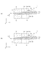
図1は、第1実施形態の加速度検出器の部分展開模式斜視図である。図2は、図1の加速度検出器の概略構成を示す模式平断面図である。図2(a)は、平面図、図2(b)は、図2(a)のA−A線での断面図である。なお、各配線は省略してあり、各構成要素の寸法比率は実際と異なる。
(First embodiment)
First, an example of an acceleration detector as a physical quantity detector will be described.
FIG. 1 is a partially developed schematic perspective view of the acceleration detector according to the first embodiment. FIG. 2 is a schematic plan sectional view showing a schematic configuration of the acceleration detector of FIG. 2A is a plan view, and FIG. 2B is a cross-sectional view taken along line AA in FIG. 2A. In addition, each wiring is abbreviate | omitted and the dimension ratio of each component differs from actual.
図1、図2に示すように、加速度検出器1は、平板状のベース部10と、ベース部10に継ぎ手部11を介して接続された矩形平板状の可動部12と、継ぎ手部11を跨いでベース部10と可動部12とに架け渡された物理量検出素子としての加速度検出素子13とを備えている。
そして、加速度検出器1は、平面視において、ベース部10から可動部12の両側(−X方向側と+X方向側)に沿って延びる部位を含み、可動部12の自由端側でX軸方向に屈曲して繋がり、ベース部10とによって可動部12を囲む略矩形の枠状に形成されている平板状の支持部14、を備えている。
As shown in FIGS. 1 and 2, the
The
可動部12は、平板の表裏面に相当する両主面12a,12bに、平面視において、一部が支持部14と重なる一対の質量部(錘)15が配置されている。質量部15は、接合材16を介して主面12a,12bに接合(固定)されている。
ベース部10、継ぎ手部11、可動部12、支持部14は、例えば、水晶の原石などから所定の角度で切り出された水晶基板を用いて一体で略平板状に形成されている。なお、可動部12と支持部14との間には、両者を分割するスリット状の貫通孔が設けられている。
ベース部10、継ぎ手部11、可動部12、支持部14の外形形状は、フォトリソグラフィー、エッチングなどの技術を用いて精度よく形成されている。
The
The
The outer shapes of the
継ぎ手部11は、ベース部10の両主面10a,10b及び可動部12の両主面12a,12b側からのハーフエッチングによって、ベース部10と可動部12とを区切るように、ベース部10と可動部12とを結ぶ方向(Y軸方向)と直交する方向(X軸方向)に沿って有底の溝部11aが形成されている。
溝部11aにより、継ぎ手部11のY軸方向に沿った断面形状(図2(b)の形状)は、略H字状に形成されている。
この継ぎ手部11により、可動部12は、主面12a(12b)と交差する第1方向としてのZ軸方向に加わる加速度に応じて、継ぎ手部11を支点(回転軸)にして主面12aと交差するZ軸方向に変位(回動)可能となっている。
The
The cross-sectional shape (shape of FIG. 2B) along the Y-axis direction of the
Due to the
質量部15の接合面積(接合材16の塗布範囲)は、熱応力の抑制の観点から、可動部12への接合に必要な面積を確保しつつ、極力小さくすることが好ましい。
質量部15は、加速度検出器1の感度向上を図るべく平面サイズを極力大きくするために、可動部12における継ぎ手部11側とは反対側の自由端側から、加速度検出素子13を避けて二股状で継ぎ手部11近傍まで延び、平面視において、略U字状に形成されている。
質量部15には、例えば、Cu(銅)、Au(金)などの金属に代表される比較的比重の大きい材料が用いられている。
接合材16には、弾性に優れたシリコーン系樹脂(変成シリコーン樹脂など)を含む接着剤として、例えば、シリコーン系熱硬化型接着剤が用いられている。
It is preferable that the bonding area of the mass part 15 (the application range of the bonding material 16) be as small as possible while securing an area necessary for bonding to the
In order to increase the plane size as much as possible in order to improve the sensitivity of the
For the
For the
加速度検出器1は、支持部14に、質量部15と支持部14とが重なる領域B(図2(a)のハッチング部分)を含むようにして、Y軸方向の全幅に亘って、Z軸方向の厚さが隣接部(肉厚部)よりも薄い肉薄部14cが形成されている。
この肉薄部14cにより、加速度検出器1は、図2(b)に示すように、質量部15と支持部14とが重なる領域Bでは、質量部15と支持部14(肉薄部14c)との間に隙間Cが設けられている。
なお、肉薄部14cは、支持部14の両主面14a,14b側からのハーフエッチングによって形成されている。また、肉薄部14cは、応力集中を緩和する観点から隣接部と斜面で接続されていることが好ましい。換言すれば、肉薄部14cは、Z軸方向に括れた形状となっていることが好ましい。
The
As shown in FIG. 2B, the
In addition, the
加速度検出素子13は、ベース部10と可動部12とを結ぶ方向(Y軸方向)に沿って延びる2本の角柱状であって、X軸方向に屈曲振動をする振動梁13a,13bを有する加速度検出部13cと、加速度検出部13cの両端に接続された一対の基部13d,13eと、を備えている。
加速度検出素子13は、2本の振動梁13a,13bと一対の基部13d,13eとで二組の音叉を構成することから、双音叉素子(双音叉型振動片)とも呼ばれている。
加速度検出素子13は、例えば、水晶の原石などから所定の角度で切り出された水晶基板を用いて、加速度検出部13cと基部13d,13eとが一体で略平板状に形成されている。また、加速度検出素子13の外形形状は、フォトリソグラフィー、エッチングなどの技術を用いて精度よく形成されている。
The
The
For example, the
加速度検出素子13は、一方の基部13dが可動部12の主面12a側に、例えば、低融点ガラス、共晶接合可能なAu/Sn合金被膜などの接合部材17を介して固定され、他方の基部13eがベース部10の主面10a側(可動部12の主面12aと同じ側)に接合部材17を介して固定されている。
なお、加速度検出素子13と、ベース部10の主面10a及び可動部12の主面12aとの間には、可動部12の変位時に加速度検出素子13とベース部10及び可動部12とが互いに接触しないように、所定の隙間が設けられている。この隙間は、本実施形態では、接合部材17の厚さで管理されている。
具体的には、例えば、ベース部10及び可動部12と加速度検出素子13との間に、所定の隙間に相当する厚さに形成されたスペーサーを挟んだ状態で、ベース部10及び可動部12と加速度検出素子13とを接合部材17によって固定し、接合後スペーサーを除去することで、隙間を所定の範囲内に管理することができる。
In the
In addition, between the
Specifically, for example, the
加速度検出素子13は、振動梁13a,13bの図示しない励振電極(駆動電極)から基部13eに引き出された引き出し電極13f,13gが、例えば、金属フィラーなどの導電性物質が混合された導電性接着剤(例えば、シリコーン系導電性接着剤)18によって、ベース部10の主面10aに設けられた接続端子10c,10dと接続されている。
詳述すると、引き出し電極13fは、導電性接着剤18を介して接続端子10cと接続され、引き出し電極13gは、導電性接着剤18を介して接続端子10dと接続されている。
The
More specifically, the
ベース部10の接続端子10c,10dは、図示しない配線によって支持部14の主面14b(ベース部10の主面10bと同じ側の主面)に設けられた外部接続端子14d,14eと接続されている。
詳述すると、接続端子10cは、ベース部10の主面10aから支持部14の主面14bに回りこんだ配線によって外部接続端子14dと接続され、接続端子10dは、ベース部10の主面10aから支持部14の主面14bに回りこんだ配線によって外部接続端子14eと接続されている。
なお、振動梁13a,13bの励振電極、引き出し電極13f,13g、接続端子10c,10d、配線、外部接続端子14d,14eは、例えば、Crを下地層とし、その上にAuが積層された構成となっている。
The
More specifically, the
The excitation electrodes of the vibrating
ここで、加速度検出器1の動作について説明する。
図3は、加速度検出器の動作について説明する模式断面図である。図3(a)は、可動部が紙面下方(−Z方向)に変位した状態を示す断面図であり、図3(b)は、可動部が紙面上方(+Z方向)に変位した状態を示す断面図である。
Here, the operation of the
FIG. 3 is a schematic cross-sectional view for explaining the operation of the acceleration detector. FIG. 3A is a cross-sectional view showing a state where the movable part is displaced downward (−Z direction) in the drawing, and FIG. 3B shows a state where the movable part is displaced upward (+ Z direction) in the drawing. It is sectional drawing.
図3(a)に示すように、加速度検出器1は、Z軸方向に加わる加速度+αに応じた慣性力によって、可動部12が、継ぎ手部11を支点にして−Z方向に変位した場合、加速度検出素子13には、Y軸方向に基部13dと基部13eとが互いに離れる方向の引っ張り力が加わり、加速度検出部13cの振動梁13a,13bに引っ張り応力が生じる。
これにより、加速度検出器1は、例えば、巻き上げられた弦楽器の弦のように、加速度検出部13cの振動梁13a,13bの振動周波数(以下、共振周波数ともいう)が高くなる方に変化する。
As shown in FIG. 3A, the
Thereby, the
一方、図3(b)に示すように、加速度検出器1は、Z軸方向に加わる加速度−αに応じた慣性力によって、可動部12が、継ぎ手部11を支点にして+Z方向に変位した場合、加速度検出素子13には、Y軸方向に基部13dと基部13eとが互いに近づく方向の圧縮力が加わり、加速度検出部13cの振動梁13a,13bに圧縮応力が生じる。
これにより、加速度検出器1は、例えば、巻き戻された弦楽器の弦のように、加速度検出部13cの振動梁13a,13bの共振周波数が低くなる方に変化する。
On the other hand, as shown in FIG. 3B, in the
Thereby, the
加速度検出器1は、この共振周波数の変化を検出している。Z軸方向に加わる加速度(+α、−α)は、この検出された共振周波数の変化の割合に応じて、ルックアップテーブルなどによって定められた数値に変換することで導出される。
The
ここで、図3(a)に示すように、加速度検出器1は、Z軸方向に加わる加速度+αが所定の大きさより大きい場合、可動部12の主面12aに固定された質量部15の、平面視において支持部14と重なる部分が支持部14の肉薄部14cに接触(衝突)する。
これにより、加速度検出器1は、加速度+αに応じて−Z方向に変位する可動部12の変位を、所定の範囲(隙間Cに相当、図2(b)参照)内に規制する。
Here, as shown in FIG. 3A, the
Thereby, the
一方、図3(b)に示すように、加速度検出器1は、Z軸方向に加わる加速度−αが所定の大きさより大きい場合、可動部12の主面12bに固定された質量部15の、平面視において支持部14と重なる部分が支持部14の肉薄部14cに接触(衝突)する。
これにより、加速度検出器1は、加速度−αに応じて+Z方向に変位する可動部12の変位を、所定の範囲(隙間Cに相当、図2(b)参照)内に規制する。
ここで、質量部15が支持部14に接触(衝突)する際の衝撃力は、肉薄部14cの撓みによって吸収(緩和)される。
On the other hand, as shown in FIG. 3 (b), the
Thereby, the
Here, the impact force when the
上述したように、第1実施形態の加速度検出器1は、可動部12の両主面12a,12bに質量部15が配置(固定)され、主面12aと交差するZ軸方向(第1方向)に加わる慣性力に応じて、可動部12が継ぎ手部11を支点にしてZ軸方向に変位可能である。そして、加速度検出器1は、平面視において、質量部15の一部が支持部14と重なるように配置されている。そして、加速度検出器1は、質量部15と支持部14とが重なる領域Bでは、質量部15と支持部14との間に隙間Cが設けられ、支持部14には、Z軸方向の厚さが隣接部(肉厚部)よりも薄い肉薄部14cが形成されている。
As described above, in the
これにより、加速度検出器1は、所定の範囲を超えた物理量としての加速度が印加された場合に、可動部12に固定された質量部15が支持部14に接触することで、可動部12の所定以上の変位を規制するストッパーの機能を果たす構成となっている。
そして、加速度検出器1は、支持部14に形成された、可動部12の変位方向であるZ軸方向の厚さが隣接部よりも薄くなっている肉薄部14cの撓みにより、質量部15が支持部14に接触(衝突)した際の衝撃が吸収(緩和)される。
この結果、加速度検出器1は、質量部15が配置(固定)された可動部12や、ベース部10と可動部12とに架け渡された加速度検出素子13の破損を、特許文献1の従来構成と比較して低減することができる。
Thereby, the
The
As a result, the
また、加速度検出器1は、肉薄部14cがZ軸方向に両側(一方の主面12a側、他方の主面12b側)から括れていることから、質量部15が支持部14に接触(衝突)した際の、可動部12の一方の主面12a側からの衝撃及び可動部12の他方の主面12b側からの衝撃を、均等に吸収(緩和)することができる。
Moreover, since the
また、加速度検出器1は、支持部14の肉薄部14cが、質量部15と支持部14とが重なる領域Bを含むように設けられていることから、肉薄部14cによって、例えば、質量部15に凸部を設けることなく、質量部15と支持部14との間の隙間Cを構成することができる。
つまり、加速度検出器1は、支持部14の肉薄部14cによって、質量部15と支持部14との間の隙間Cの確保と、質量部15が支持部14に接触(衝突)する際の衝撃の吸収(緩和)とを、両立させることができる。
Moreover, since the
That is, the
なお、加速度検出器1は、Z軸方向に加わる加速度が一方向のみ(+αのみ、または−αのみ)の場合には、支持部14に接触しない方の質量部15は、平面視において支持部14と重ならない形状としてもよく、質量部15そのものを除去してもよい。
また、加速度検出器1は、加速度検出素子13を可動部12の主面12a側に代えて、主面12b側に備えてもよく、主面12a側及び主面12b側の両方に備えてもよい。
また、加速度検出器1は、加速度検出素子13の引き出し電極13f,13gと、ベース部10の接続端子10c,10dとの接続を、導電性接着剤18に代えてAu、Alなどの金属ワイヤーを用いた、ワイヤーボンディングによって行ってもよい。
なお、これらの付帯事項は、以下の変形例にも適用可能である。
In the
The
Further, the
These incidental items can also be applied to the following modifications.
(変形例)
次に、第1実施形態の変形例について説明する。
図4は、第1実施形態の変形例の加速度検出器の概略構成を示す模式平断面図である。図4(a)は、平面図、図4(b)は、図4(a)のA−A線での断面図、図4(c)は、図4(a)のD−D線での断面図である。なお、各配線は省略してあり、各構成要素の寸法比率は実際と異なる。
また、上記第1実施形態との共通部分には、同一符号を付して詳細な説明を省略し、上記第1実施形態と異なる部分を中心に説明する。
(Modification)
Next, a modification of the first embodiment will be described.
FIG. 4 is a schematic plan sectional view showing a schematic configuration of an acceleration detector according to a modification of the first embodiment. 4A is a plan view, FIG. 4B is a cross-sectional view taken along line AA in FIG. 4A, and FIG. 4C is a DD line in FIG. 4A. FIG. In addition, each wiring is abbreviate | omitted and the dimension ratio of each component differs from actual.
Also, common parts with the first embodiment will be denoted by the same reference numerals, detailed description thereof will be omitted, and different parts from the first embodiment will be mainly described.
図4に示すように、加速度検出器2は、支持部14における可動部12の一方側(−X方向側)に沿って延びる部位と、他方側(+X方向側)に沿って延びる部位とのそれぞれに、X軸方向の全幅に亘って、Z軸方向の厚さが隣接部よりも薄い肉薄部14c1,14c2が形成されている。
なお、肉薄部14c1,14c2は、支持部14の両主面14a,14b側からのハーフエッチングによって形成されている。また、肉薄部14c1,14c2は、応力集中を緩和する観点から隣接部と斜面で接続されていることが好ましい。換言すれば、肉薄部14c1,14c2は、Z軸方向に括れた形状となっていることが好ましい。
なお、加速度検出器2は、支持部14における質量部15と重なる部分(領域B)には、肉薄部が形成されていない。
As shown in FIG. 4, the
The thin portions 14c1 and 14c2 are formed by half-etching from both
In the
加速度検出器2は、質量部15に可動部12の主面12a(12b)側に突出する円柱状(円板状)の凸部15aを有し、凸部15aの先端部が、可動部12の主面12a(12b)に接合材16を介して接合(固定)されている。
なお、凸部15aは、熱応力の抑制の観点から、可動部12への接合に必要な面積を確保しつつ、平面サイズを極力小さくすることが好ましい。また、質量部15は、接合時の傾き回避の観点から、平面視において、質量部15の重心が凸部15a内に収まることが好ましい。
The
In addition, it is preferable that the
加速度検出器2は、質量部15に凸部15aが設けられたことによって、質量部15と支持部14とが重なる領域Bでは、質量部15と支持部14との間に隙間Cが確保されている。
なお、加速度検出器2の動作については、上記第1実施形態に準じるので説明は省略する。
In the
The operation of the
上述したように、変形例の加速度検出器2は、支持部14が、平面視において、ベース部10とによって可動部12を囲む枠状に形成され、支持部14における可動部12の一方側(−X方向側)と他方側(+X方向側)とのそれぞれに、肉薄部14c1,14c2が形成されている。
このことから、加速度検出器2は、支持部14における可動部12の一方側の部位と他方側の部位とのそれぞれに形成された肉薄部14c1,14c2の撓みによって、質量部15が支持部14に接触(衝突)した際の衝撃を吸収(緩和)することができる。
この結果、加速度検出器2は、質量部15が配置(固定)された可動部12や、ベース部10と可動部12とに架け渡された加速度検出素子13の破損を、例えば、肉薄部14c1,14c2が可動部12の一方側にしかない場合と比較して、更に低減することができる。
なお、肉薄部14c1,14c2は、支持部14の主面14a側または主面14b側の一方側からのエッチング(片側エッチング)により形成されてもよい。
As described above, in the
Therefore, in the
As a result, the
The thin portions 14c1 and 14c2 may be formed by etching (one-side etching) from one side of the
なお、加速度検出器2は、支持部14における可動部12の一方側(−X方向側)と他方側(+X方向側)とのそれぞれに、肉薄部14c1,14c2に加えて、更に肉薄部を形成してもよい。
また、本変形例と第1実施形態とを組み合わせた構成としてもよい。例えば、第1実施形態の支持部14の対応する場所に、本変形例の肉薄部14c1,14c2を形成してもよい。
これらによれば、加速度検出器1,2は、衝撃吸収(衝撃緩和)性能を更に向上させることができる。
In addition to the thin portions 14c1 and 14c2, the
Moreover, it is good also as a structure which combined this modification and 1st Embodiment. For example, the thin portions 14c1 and 14c2 of the present modification may be formed at locations corresponding to the
According to these, the
(第2実施形態)
次に、上記第1実施形態及び変形例で述べた加速度検出器を備えた物理量検出デバイスとしての加速度検出デバイスについて説明する。
図5は、第2実施形態の加速度検出デバイスの概略構成を示す模式平断面図である。図5(a)は、リッド(蓋体)側から俯瞰した平面図であり、図5(b)は、図5(a)のE−E線での断面図である。なお、平面図では、リッドを省略してある。また、各配線は省略してあり、各構成要素の寸法比率は実際と異なる。
なお、上記第1実施形態との共通部分には、同一符号を付して詳細な説明を省略し、上記第1実施形態と異なる部分を中心に説明する。
(Second Embodiment)
Next, an acceleration detection device as a physical quantity detection device including the acceleration detector described in the first embodiment and the modification will be described.
FIG. 5 is a schematic plan sectional view showing a schematic configuration of the acceleration detection device of the second embodiment. Fig.5 (a) is a top view looked down from the lid (lid body) side, FIG.5 (b) is sectional drawing in the EE line | wire of Fig.5 (a). In the plan view, the lid is omitted. Moreover, each wiring is abbreviate | omitted and the dimension ratio of each component differs from actual.
In addition, the same code | symbol is attached | subjected to a common part with the said 1st Embodiment, detailed description is abbreviate | omitted, and it demonstrates centering on a different part from the said 1st Embodiment.
図5に示すように、加速度検出デバイス3は、上記第1実施形態で述べた加速度検出器1と、加速度検出器1を収容するパッケージ20と、を備えている。
パッケージ20は、平面形状が略矩形で凹部を有したパッケージベース21と、パッケージベース21の凹部を覆う平面形状が略矩形で平板状のリッド22と、を有し、略直方体形状に形成されている。
パッケージベース21には、セラミックグリーンシートを成形して積層し焼成した酸化アルミニウム質焼結体、水晶、ガラス、シリコンなどが用いられている。
リッド22には、パッケージベース21と同材料、または、コバール、42アロイ、ステンレス鋼などの金属が用いられている。
As shown in FIG. 5, the
The
The
The lid 22 is made of the same material as the
パッケージベース21には、内底面(凹部の内側の底面)23の外周部分から凹部の内壁に沿って突出した2箇所の段差部23aに、内部端子24,25が設けられている。
内部端子24,25は、加速度検出器1の支持部14に設けられた外部接続端子14d,14eと対向する位置(平面視において重なる位置)に設けられている。なお、前述したように、外部接続端子14dは、ベース部10の接続端子10cと接続され、外部接続端子14eは、ベース部10の接続端子10dと接続されている。
The
The
パッケージベース21の外底面(内底面23の反対側の面、外側の底面)26には、電子機器などの外部部材に実装される際に用いられる一対の外部端子27,28が形成されている。
外部端子27,28は、図示しない内部配線によって内部端子24,25と接続されている。例えば、外部端子27は、内部端子24と接続され、外部端子28は、内部端子25と接続されている。
内部端子24,25及び外部端子27,28は、W、Moなどのメタライズ層にNi、Auなどの各被膜をメッキなどの方法により積層した金属膜からなる。
A pair of
The
The
パッケージベース21には、凹部の底部にパッケージ20の内部を封止する封止部29が設けられている。
封止部29は、パッケージベース21に形成された、外底面26側の孔径が内底面23側の孔径より大きい段付きの貫通孔29aに、Au/Ge合金、ハンダなどからなる封止材29bを投入し、加熱溶融後、固化させることでパッケージ20の内部を気密に封止する構成となっている。
The
The sealing
加速度検出デバイス3は、加速度検出器1の支持部14の外部接続端子14d,14e及び他の2箇所の固定部分が、接着剤30を介して、パッケージベース21の段差部23aに固定されている。
接着剤30には、例えば、金属フィラーなどの導電性物質が混合された導電性接着剤(例えば、シリコーン系導電性接着剤)が用いられている。これにより、加速度検出デバイス3は、加速度検出器1の外部接続端子14d,14eと内部端子24,25とが電気的に接続される。
なお、外部接続端子14d,14e以外の他の2箇所の固定部分には、金属フィラーなどの導電性物質を含まない接着剤(例えば、シリコーン系接着剤)を用いてもよい。
In the
For the adhesive 30, for example, a conductive adhesive (for example, a silicone-based conductive adhesive) mixed with a conductive substance such as a metal filler is used. Thereby, in the
Note that an adhesive that does not contain a conductive substance such as a metal filler (for example, a silicone-based adhesive) may be used for the other two fixed portions other than the
加速度検出デバイス3は、加速度検出器1がパッケージベース21の内部端子24,25と接続された状態で、パッケージベース21の凹部がリッド22により覆われ、パッケージベース21とリッド22とがシームリング、低融点ガラス、接着剤などの接合部材22aで接合される。
加速度検出デバイス3は、リッド22の接合後、パッケージ20の内部が減圧された状態(真空度の高い状態)で、封止部29の貫通孔29aに封止材29bが投入され、加熱溶融後、固化されることにより、パッケージ20の内部が気密に封止される。
なお、パッケージ20の内部は、窒素、ヘリウム、アルゴンなどの不活性ガスが充填されていてもよい。
なお、パッケージは、パッケージベース及びリッドの両方に凹部を有していてもよい。
In the
In the
Note that the inside of the
The package may have a recess in both the package base and the lid.
加速度検出デバイス3は、外部端子27,28、内部端子24,25、外部接続端子14d,14e、接続端子10c,10dなどを経由して加速度検出器1の励振電極に印加される駆動信号によって、加速度検出器1の振動梁13a,13bが所定の周波数で発振(共振)する。
そして、加速度検出デバイス3は、加わる加速度に応じて変化する加速度検出器1の共振周波数を出力信号として出力する。
The
And the
上述したように、第2実施形態の加速度検出デバイス3は、加速度検出器1を備えたことから、上記第1実施形態に記載された効果を奏する加速度検出デバイスを提供することができる。
なお、加速度検出デバイス3は、加速度検出器1に代えて加速度検出器2を備えた場合においても、上記と同様の効果及び加速度検出器2の特有の効果を奏する加速度検出デバイスを提供することができる。
As described above, since the
Note that the
(第3実施形態)
次に、上記実施形態及び変形例で述べた加速度検出器を備えた電子機器としての傾斜計について説明する。
図6は、第3実施形態の傾斜計を示す模式斜視図である。図7は、傾斜計の内部に収容された傾斜センサーモジュールの概略構成を示す部分展開模式斜視図である。
図6、図7に示すように、傾斜計4は、上記第1実施形態で述べた加速度検出器1を、傾斜センサーモジュール5の傾斜センサーとして備えている。
図7に示すように、傾斜センサーモジュール5は、ベース基板201と、断熱基板202と、基台203と、加速度検出器1を備えた加速度検出デバイス3と、発振器204と、キャップ205と、を備え、傾斜計4の内部に収容されている。
(Third embodiment)
Next, an inclinometer as an electronic apparatus provided with the acceleration detector described in the embodiment and the modification will be described.
FIG. 6 is a schematic perspective view showing the inclinometer of the third embodiment. FIG. 7 is a partially developed schematic perspective view showing a schematic configuration of the tilt sensor module housed in the inclinometer.
As shown in FIGS. 6 and 7, the inclinometer 4 includes the
As shown in FIG. 7, the
矩形平板状のベース基板201には、例えば、FR−4(ガラス布入りエポキシ樹脂基板)が用いられ、搭載された回路素子201aによって、加速度検出デバイス3や発振器204に関わる周辺回路が構成されている。また、ベース基板201には、外部(傾斜計本体)との入出力のための端子201bや、傾斜計本体への取り付け孔201cが形成されている。
矩形平板状の断熱基板202は、PBT(ポリブチレンテレフタレート)、LCP(液晶ポリマー)などの低熱伝導率で耐熱性、電気特性、寸法安定性などに優れた樹脂が用いられ、厚み方向に貫通して固定されている細いピン状(棒状)の複数の接続ピン202aによって、ベース基板201に隙間を有して接続されている。
基台203は、アルミニウム、アルミニウム合金、銅、銅合金などの金属を用いて、削り出しまたは板金加工により略直方体形状に形成され、断熱基板202に、例えば、接着剤などで固定されている。なお、基台203には、上記の樹脂や酸化アルミニウム質焼結体(セラミック類)などを用いてもよい。
For example, FR-4 (epoxy resin substrate with glass cloth) is used for the rectangular
The rectangular flat
The
加速度検出デバイス3及び発振器204は、基台203の側面(断熱基板202に対して直立する面)に、例えば、導電性接着剤などによって固定されている。2つの加速度検出デバイス3は、基台203における隣り合う直角に接続された側面にそれぞれ固定されている。これにより、傾斜センサーモジュール5は、互いに直交する2軸に対する傾斜を検出することができる。
発振器204は、基台203における一方の加速度検出デバイス3が固定された側面と対向する側面(換言すれば、他方の加速度検出デバイス3が固定された側面と隣り合う側面)に固定されている。
加速度検出デバイス3及び発振器204は、リード線206によって断熱基板202の接続ピン202aに接続され、接続ピン202aを経由してベース基板201に接続されている。
The
The
The
なお、一方の加速度検出デバイス3の近傍には、周辺の温度を検知するサーミスター207(温度センサー)が備えられている。サーミスター207は、周辺の温度を検知して、加速度検出デバイス3及び発振器204の周波数特性の温度補償(温度補正)をする際の、温度検知手段として設けられている。
サーミスター207は、上記加速度検出デバイス3及び発振器204と同様に、リード線206によって断熱基板202の接続ピン202aに接続され、接続ピン202aを経由してベース基板201に接続されている。
発振器204は、加速度検出時における加速度検出デバイス3(加速度検出器1)の共振周波数と比較する比較回路の基準周波数(基準共振周波数)発振源として備えられている。
A thermistor 207 (temperature sensor) that detects the ambient temperature is provided in the vicinity of one
Similar to the
The
ベース基板201側に開口部を備えた箱状のキャップ205には、断熱基板202と同様に低熱伝導率の樹脂(PBT、ABS、PCなど)が用いられ、ベース基板201上の断熱基板202、基台203、加速度検出デバイス3、サーミスター207、発振器204、回路素子201aなどを覆うようにベース基板201に固定されている。
For the box-shaped
これらの構成により、傾斜センサーモジュール5は、周囲の温度変化の加速度検出デバイス3への到達を遅延させることができる。詳述すると、ベース基板201からの接触による熱伝導は、細いピン状の接続ピン202aや低熱伝導率の樹脂が用いられた断熱基板202により遅延され、加速度検出デバイス3の周辺の大気の対流や、外部部材の放射熱(輻射熱)による熱伝導は、低熱伝導率の樹脂が用いられたキャップ205による外気及び放射熱源からの遮断によって遅延される。
このように、傾斜センサーモジュール5は、周囲の温度変化の加速度検出デバイス3への到達を遅延させることで、加速度検出デバイス3の温度変化をなだらかにすることが可能となることから、加速度検出デバイス3(加速度検出器1)の、例えば、加速度検出精度などの加速度検出特性を良好な状態に維持することができる。
With these configurations, the
As described above, the
図6に戻って、傾斜計4は、例えば、山の斜面、道路の法面、盛土の擁壁面などの被計測場所に設置される。傾斜計4は、外部からケーブル40を介して電源が供給され、または電源を内蔵し、図示しない駆動回路によって傾斜センサーモジュール5(加速度検出器1)に駆動信号が送られている。
そして、傾斜計4は、図示しない検出回路によって、傾斜センサーモジュール5(加速度検出器1)に加わる重力加速度に応じて変化する共振周波数から、傾斜計4の姿勢の変化(傾斜計4に対する重力加速度が加わる方向の変化)を検出し、それを角度に換算して、例えば、無線またはケーブル40などで基地局にデータ転送する。これにより、傾斜計4は、日常の管理や異常の早期発見に貢献することができる。
なお、傾斜計4は、加速度検出器1に代えて加速度検出器2を傾斜センサーとして備えていてもよい。
Returning to FIG. 6, the inclinometer 4 is installed at a measurement site such as a mountain slope, a road slope, or a retaining wall of a bank. The inclinometer 4 is supplied with power from the outside via a
The inclinometer 4 detects a change in the attitude of the inclinometer 4 (gravitational acceleration with respect to the inclinometer 4) from a resonance frequency that changes according to gravitational acceleration applied to the inclination sensor module 5 (acceleration detector 1) by a detection circuit (not shown). Change in the direction in which the data is added), converted into an angle, and data is transferred to the base station by radio or
Note that the inclinometer 4 may include the
上述した加速度検出器1,2は、上記傾斜計に限らず、地震計、ナビゲーション装置、姿勢制御装置、ゲームコントローラー、携帯電話などの加速度センサー、傾斜センサーなどとして好適に用いることができ、いずれの場合にも上記実施形態及び変形例で説明した効果を奏する電子機器を提供することができる。
The above-described
なお、上記各実施形態及び変形例において、ベース部10、継ぎ手部11、可動部12、支持部14の材料は、水晶に限定するものではなく、ガラス、またはシリコンなどの半導体材料であってもよい。
また、加速度検出素子13の基材は、水晶に限定するものではなく、タンタル酸リチウム(LiTaO3)、四ホウ酸リチウム(Li2B4O7)、ニオブ酸リチウム(LiNbO3)、チタン酸ジルコン酸鉛(PZT)、酸化亜鉛(ZnO)、窒化アルミニウム(AlN)などの圧電材料、または酸化亜鉛(ZnO)、窒化アルミニウム(AlN)などの圧電材料を被膜として備えたシリコンなどの半導体材料であってもよい。
In each of the above-described embodiments and modifications, the material of the
The base material of the
以上、物理量検出器として加速度検出器を例に挙げて本発明を説明したが、本発明はこれに限定されず、加速度検出結果から力、速度、距離などを検出する物理量検出器にも適用できる。 The present invention has been described above by taking the acceleration detector as an example of the physical quantity detector. However, the present invention is not limited to this, and can be applied to a physical quantity detector that detects force, speed, distance, and the like from the acceleration detection result. .
1…物理量検出器としての加速度検出器、10…ベース部、10a,10b…主面、10c,10d…接続端子、11…継ぎ手部、11a…溝部、12…可動部、12a,12b…主面、13…物理量検出素子としての加速度検出素子、13a,13b…振動梁、13c…加速度検出部、13d,13e…基部、13f,13g…引き出し電極、14…支持部、14a,14b…主面、14c…肉薄部、14d,14e…外部接続端子、15…質量部、16…接合材、17…接合部材、18…導電性接着剤。
DESCRIPTION OF
Claims (6)
該ベース部に接続された可動部と、
前記ベース部と前記可動部とに架け渡されて配置された物理量検出素子と、
前記可動部の主面に配置された質量部と、
前記ベース部から延出し、且つ、前記可動部の主面の法線方向から見た平面視において前記質量部と重なる領域を有した支持部と、を備え、
前記可動部は、前記法線方向に変位可能であり、
前記支持部の前記質量部と重なる領域では、前記質量部と前記支持部との間に隙間があり、
前記支持部には、肉厚部と、前記肉厚部よりも厚さが薄い肉薄部と、が備えられ、
前記肉薄部は、前記支持部の互いに表裏関係にある両方の面が括れて設けられていることを特徴とする物理量検出器。 A base part;
A movable part connected to the base part;
A physical quantity detection element disposed across the base part and the movable part;
A mass part disposed on the main surface of the movable part;
A support portion extending from the base portion and having a region overlapping the mass portion in a plan view as viewed from the normal direction of the main surface of the movable portion,
The movable part is displaceable in the normal direction;
In the region of the support part that overlaps the mass part, there is a gap between the mass part and the support part,
The support portion includes a thick portion and a thin portion having a thickness smaller than the thick portion ,
The physical quantity detector, wherein the thin portion is provided so that both surfaces of the support portion which are in a front-back relationship are bundled .
前記支持部は、前記ベース部から前記可動部に沿って延びる部位を備え、
前記肉薄部は、前記部位に備えられていることを特徴とする物理量検出器。 The physical quantity detector according to claim 1,
The support portion includes a portion extending from the base portion along the movable portion,
The physical quantity detector, wherein the thin portion is provided in the part.
前記肉薄部は、前記質量部と重なる領域に備えられていることを特徴とする物理量検出器。 The physical quantity detector according to claim 1 or 2,
The physical quantity detector, wherein the thin portion is provided in a region overlapping the mass portion.
前記支持部は、前記ベース部の一端から前記可動部に沿って延びる第1部位と、前記ベース部の他端から前記可動部に沿って延びる第2部位と、前記第1部位および前記第2部位の延出する方向と交差する方向に延出し且つ前記第1部位と前記第2部位とを連結する連結部位と、を備え、
前記肉薄部は、前記第1部位および前記第2部位の少なくとも一方に備えられていることを特徴とする物理量検出器。 The physical quantity detector according to any one of claims 1 to 3,
The support part includes a first part extending along the movable part from one end of the base part, a second part extending along the movable part from the other end of the base part, the first part, and the second part. A connecting portion extending in a direction intersecting with the extending direction of the portion and connecting the first portion and the second portion;
The physical quantity detector, wherein the thin portion is provided in at least one of the first part and the second part.
前記物理量検出器を収容するパッケージと、
を備えたことを特徴とする物理量検出デバイス。 A physical quantity detector according to any one of claims 1 to 4 ,
A package containing the physical quantity detector;
A physical quantity detection device comprising:
Priority Applications (1)
| Application Number | Priority Date | Filing Date | Title |
|---|---|---|---|
| JP2011214087A JP5838694B2 (en) | 2011-09-29 | 2011-09-29 | Physical quantity detector, physical quantity detection device, and electronic apparatus |
Applications Claiming Priority (1)
| Application Number | Priority Date | Filing Date | Title |
|---|---|---|---|
| JP2011214087A JP5838694B2 (en) | 2011-09-29 | 2011-09-29 | Physical quantity detector, physical quantity detection device, and electronic apparatus |
Publications (3)
| Publication Number | Publication Date |
|---|---|
| JP2013072836A JP2013072836A (en) | 2013-04-22 |
| JP2013072836A5 JP2013072836A5 (en) | 2014-10-30 |
| JP5838694B2 true JP5838694B2 (en) | 2016-01-06 |
Family
ID=48477437
Family Applications (1)
| Application Number | Title | Priority Date | Filing Date |
|---|---|---|---|
| JP2011214087A Expired - Fee Related JP5838694B2 (en) | 2011-09-29 | 2011-09-29 | Physical quantity detector, physical quantity detection device, and electronic apparatus |
Country Status (1)
| Country | Link |
|---|---|
| JP (1) | JP5838694B2 (en) |
Families Citing this family (2)
| Publication number | Priority date | Publication date | Assignee | Title |
|---|---|---|---|---|
| JP6897187B2 (en) * | 2017-03-16 | 2021-06-30 | セイコーエプソン株式会社 | Physical quantity detectors, physical quantity detection devices, electronic devices and mobiles |
| JP2019158476A (en) * | 2018-03-09 | 2019-09-19 | セイコーエプソン株式会社 | Physical quantity sensor device, clinometer using physical quantity sensor device, inertia measuring device, structure monitoring device, and moving body |
Family Cites Families (5)
| Publication number | Priority date | Publication date | Assignee | Title |
|---|---|---|---|---|
| JPS63165572U (en) * | 1987-04-15 | 1988-10-27 | ||
| JP2600393B2 (en) * | 1989-09-25 | 1997-04-16 | 日産自動車株式会社 | Manufacturing method of semiconductor acceleration sensor |
| JPH07229924A (en) * | 1994-02-21 | 1995-08-29 | Tokai Rika Co Ltd | Acceleration sensor and its manufacture |
| JP2009133807A (en) * | 2007-10-30 | 2009-06-18 | Kyocera Corp | Sensor and sensor system |
| JP2011064652A (en) * | 2009-09-18 | 2011-03-31 | Seiko Epson Corp | Acceleration detector |
-
2011
- 2011-09-29 JP JP2011214087A patent/JP5838694B2/en not_active Expired - Fee Related
Also Published As
| Publication number | Publication date |
|---|---|
| JP2013072836A (en) | 2013-04-22 |
Similar Documents
| Publication | Publication Date | Title |
|---|---|---|
| JP5678741B2 (en) | Acceleration detector, acceleration detection device, and electronic apparatus | |
| JP2013050321A (en) | Physical quantity detector and electronic apparatus | |
| JP5896114B2 (en) | Physical quantity detection device, physical quantity detector, and electronic device | |
| US8919200B2 (en) | Physical quantity detection device, physical quantity detector, and electronic device | |
| US8624339B2 (en) | Vibrating device and electronic apparatus | |
| JP2012193971A (en) | Sensor module, sensor device, manufacturing method of sensor device and electronic apparatus | |
| JP5779946B2 (en) | Manufacturing method of sensor device | |
| JP5505189B2 (en) | Vibration device and electronic equipment | |
| JP5712755B2 (en) | Acceleration detector, acceleration detection device, and electronic apparatus | |
| JP5838694B2 (en) | Physical quantity detector, physical quantity detection device, and electronic apparatus | |
| JP5982889B2 (en) | Physical quantity sensor module and electronic device | |
| JP6517553B2 (en) | Angular velocity sensor | |
| JP2012237664A (en) | Physical quantity sensor and electronic apparatus | |
| CN113257746B (en) | Vibration device | |
| JP2012242344A (en) | Acceleration detector, acceleration detection device and electronic apparatus | |
| JP5867631B2 (en) | Acceleration detector, acceleration detection device, and electronic apparatus | |
| JP2013024828A (en) | Physical quantity detector, physical quantity detection device, electronic apparatus and manufacturing method of physical quantity detector | |
| KR20070027450A (en) | Angular velocity sensor | |
| JP2014098565A (en) | Electronic device, method of manufacturing electronic device, electronic apparatus, and moving body | |
| JP5950087B2 (en) | Physical quantity detection device, physical quantity detector, and electronic device | |
| JP2012167941A (en) | Sensor device, motion sensor, electronic equipment | |
| JP5451266B2 (en) | Electronic devices | |
| JP2013246121A (en) | Pressure sensor element and method for manufacturing the same, pressure sensor, and electronic apparatus | |
| JP2011133299A (en) | Sensor device, sensor device manufacturing method, motion sensor, and motion sensor manufacturing method | |
| JP2013170865A (en) | Physical quantity detection device, physical quantity detector, and electronic apparatus |
Legal Events
| Date | Code | Title | Description |
|---|---|---|---|
| A521 | Request for written amendment filed |
Free format text: JAPANESE INTERMEDIATE CODE: A523 Effective date: 20140912 |
|
| A621 | Written request for application examination |
Free format text: JAPANESE INTERMEDIATE CODE: A621 Effective date: 20140912 |
|
| RD04 | Notification of resignation of power of attorney |
Free format text: JAPANESE INTERMEDIATE CODE: A7424 Effective date: 20150107 |
|
| A977 | Report on retrieval |
Free format text: JAPANESE INTERMEDIATE CODE: A971007 Effective date: 20150630 |
|
| A131 | Notification of reasons for refusal |
Free format text: JAPANESE INTERMEDIATE CODE: A131 Effective date: 20150707 |
|
| A521 | Request for written amendment filed |
Free format text: JAPANESE INTERMEDIATE CODE: A523 Effective date: 20150904 |
|
| TRDD | Decision of grant or rejection written | ||
| A01 | Written decision to grant a patent or to grant a registration (utility model) |
Free format text: JAPANESE INTERMEDIATE CODE: A01 Effective date: 20151013 |
|
| A61 | First payment of annual fees (during grant procedure) |
Free format text: JAPANESE INTERMEDIATE CODE: A61 Effective date: 20151026 |
|
| R150 | Certificate of patent or registration of utility model |
Ref document number: 5838694 Country of ref document: JP Free format text: JAPANESE INTERMEDIATE CODE: R150 |
|
| S531 | Written request for registration of change of domicile |
Free format text: JAPANESE INTERMEDIATE CODE: R313531 |
|
| R350 | Written notification of registration of transfer |
Free format text: JAPANESE INTERMEDIATE CODE: R350 |
|
| LAPS | Cancellation because of no payment of annual fees |