JP5826568B2 - コネクタ - Google Patents
コネクタ Download PDFInfo
- Publication number
- JP5826568B2 JP5826568B2 JP2011191893A JP2011191893A JP5826568B2 JP 5826568 B2 JP5826568 B2 JP 5826568B2 JP 2011191893 A JP2011191893 A JP 2011191893A JP 2011191893 A JP2011191893 A JP 2011191893A JP 5826568 B2 JP5826568 B2 JP 5826568B2
- Authority
- JP
- Japan
- Prior art keywords
- connector
- actuator
- locking
- insertion port
- housing
- Prior art date
- Legal status (The legal status is an assumption and is not a legal conclusion. Google has not performed a legal analysis and makes no representation as to the accuracy of the status listed.)
- Active
Links
Images


Classifications
-
- H—ELECTRICITY
- H01—ELECTRIC ELEMENTS
- H01R—ELECTRICALLY-CONDUCTIVE CONNECTIONS; STRUCTURAL ASSOCIATIONS OF A PLURALITY OF MUTUALLY-INSULATED ELECTRICAL CONNECTING ELEMENTS; COUPLING DEVICES; CURRENT COLLECTORS
- H01R12/00—Structural associations of a plurality of mutually-insulated electrical connecting elements, specially adapted for printed circuits, e.g. printed circuit boards [PCB], flat or ribbon cables, or like generally planar structures, e.g. terminal strips, terminal blocks; Coupling devices specially adapted for printed circuits, flat or ribbon cables, or like generally planar structures; Terminals specially adapted for contact with, or insertion into, printed circuits, flat or ribbon cables, or like generally planar structures
- H01R12/70—Coupling devices
- H01R12/77—Coupling devices for flexible printed circuits, flat or ribbon cables or like structures
- H01R12/79—Coupling devices for flexible printed circuits, flat or ribbon cables or like structures connecting to rigid printed circuits or like structures
-
- H—ELECTRICITY
- H01—ELECTRIC ELEMENTS
- H01R—ELECTRICALLY-CONDUCTIVE CONNECTIONS; STRUCTURAL ASSOCIATIONS OF A PLURALITY OF MUTUALLY-INSULATED ELECTRICAL CONNECTING ELEMENTS; COUPLING DEVICES; CURRENT COLLECTORS
- H01R12/00—Structural associations of a plurality of mutually-insulated electrical connecting elements, specially adapted for printed circuits, e.g. printed circuit boards [PCB], flat or ribbon cables, or like generally planar structures, e.g. terminal strips, terminal blocks; Coupling devices specially adapted for printed circuits, flat or ribbon cables, or like generally planar structures; Terminals specially adapted for contact with, or insertion into, printed circuits, flat or ribbon cables, or like generally planar structures
- H01R12/50—Fixed connections
- H01R12/59—Fixed connections for flexible printed circuits, flat or ribbon cables or like structures
- H01R12/592—Fixed connections for flexible printed circuits, flat or ribbon cables or like structures connections to contact elements
-
- H—ELECTRICITY
- H01—ELECTRIC ELEMENTS
- H01R—ELECTRICALLY-CONDUCTIVE CONNECTIONS; STRUCTURAL ASSOCIATIONS OF A PLURALITY OF MUTUALLY-INSULATED ELECTRICAL CONNECTING ELEMENTS; COUPLING DEVICES; CURRENT COLLECTORS
- H01R12/00—Structural associations of a plurality of mutually-insulated electrical connecting elements, specially adapted for printed circuits, e.g. printed circuit boards [PCB], flat or ribbon cables, or like generally planar structures, e.g. terminal strips, terminal blocks; Coupling devices specially adapted for printed circuits, flat or ribbon cables, or like generally planar structures; Terminals specially adapted for contact with, or insertion into, printed circuits, flat or ribbon cables, or like generally planar structures
- H01R12/70—Coupling devices
- H01R12/82—Coupling devices connected with low or zero insertion force
- H01R12/85—Coupling devices connected with low or zero insertion force contact pressure producing means, contacts activated after insertion of printed circuits or like structures
- H01R12/88—Coupling devices connected with low or zero insertion force contact pressure producing means, contacts activated after insertion of printed circuits or like structures acting manually by rotating or pivoting connector housing parts
-
- H—ELECTRICITY
- H01—ELECTRIC ELEMENTS
- H01R—ELECTRICALLY-CONDUCTIVE CONNECTIONS; STRUCTURAL ASSOCIATIONS OF A PLURALITY OF MUTUALLY-INSULATED ELECTRICAL CONNECTING ELEMENTS; COUPLING DEVICES; CURRENT COLLECTORS
- H01R13/00—Details of coupling devices of the kinds covered by groups H01R12/70 or H01R24/00 - H01R33/00
- H01R13/62—Means for facilitating engagement or disengagement of coupling parts or for holding them in engagement
- H01R13/629—Additional means for facilitating engagement or disengagement of coupling parts, e.g. aligning or guiding means, levers, gas pressure electrical locking indicators, manufacturing tolerances
- H01R13/62983—Linear camming means or pivoting lever for connectors for flexible or rigid printed circuit boards, flat or ribbon cables
- H01R13/62988—Lever acting directly on flexible or rigid printed circuit boards, flat or ribbon cables, e.g. recess provided to this purposeon the surface or edge of the flexible or rigid printed circuit boards, flat or ribbon cables
-
- H—ELECTRICITY
- H01—ELECTRIC ELEMENTS
- H01R—ELECTRICALLY-CONDUCTIVE CONNECTIONS; STRUCTURAL ASSOCIATIONS OF A PLURALITY OF MUTUALLY-INSULATED ELECTRICAL CONNECTING ELEMENTS; COUPLING DEVICES; CURRENT COLLECTORS
- H01R12/00—Structural associations of a plurality of mutually-insulated electrical connecting elements, specially adapted for printed circuits, e.g. printed circuit boards [PCB], flat or ribbon cables, or like generally planar structures, e.g. terminal strips, terminal blocks; Coupling devices specially adapted for printed circuits, flat or ribbon cables, or like generally planar structures; Terminals specially adapted for contact with, or insertion into, printed circuits, flat or ribbon cables, or like generally planar structures
- H01R12/70—Coupling devices
- H01R12/71—Coupling devices for rigid printing circuits or like structures
- H01R12/712—Coupling devices for rigid printing circuits or like structures co-operating with the surface of the printed circuit or with a coupling device exclusively provided on the surface of the printed circuit
Description
接点部及び被係止部を備え且つ板状又はシート状の対象物を、前端に有する挿入口から後方へ挿入されるコネクタであって、
コンタクトと、
係止部及び載置部を有し且つ前記コンタクトを保持するハウジングと、
前記対象物の前記挿入口への挿入が可能となる開位置と、前記挿入口に挿入された前記対象物の前記接点部と前記コンタクトとが接続される閉位置との間で回動可能となるように前記ハウジングに保持されるアクチュエータとを備え、
前記アクチュエータが前記開位置にあるとき、前記挿入口へ挿入された前記対象物の前記被係止部と前記係止部とが係止することにより、前記対象物の前方への移動が一時的に防止され、
前記アクチュエータが前記閉位置にあるとき、前記対象物は前記アクチュエータと前記載置部との間で挟持される
コネクタが得られる。
前記係止部は、前後方向に直交する上方に突出するように前記載置部上に形成されている
コネクタが得られる。
前記係止部は、頂部と、前記頂部から前記載置部へ傾斜し前記対象物を前記頂部までガイドする傾斜部と、前記頂部よりも後方に形成され前記被係止部と当接する係止面とを有している
コネクタが得られる。
前記頂部は、前記係止部の前記前後方向における中点よりも後方に位置している
コネクタが得られる。
前記ハウジングは、前記対象物を前記挿入口へガイドするためのガイド部を有し、
前記傾斜部の傾斜角度は、前記ガイド部の傾斜角度と略等しい
コネクタが得られる。
前記アクチュエータが前記開位置にあるときに前記対象物の主面を前記載置部へ向けて押さえることにより前記対象物の前記上方への移動を一時的に防止する押さえ部を更に備えている
コネクタが得られる。
前記押さえ部は、弾性を有し、且つ、前記対象物の前記主面に当接する当接部を備えており、
前記対象物が挿入されていない状態において、前記当接部と前記載置部との上下方向における距離は、前記対象物の厚さよりも小さい
コネクタが得られる。
前記ハウジングを少なくとも部分的に覆い、前記ハウジングと共に前記挿入口を規定するシェルを更に備え、
前記押さえ部は、前記シェルと一体に形成され前記シェルの前端から後斜め下方向に向かって前記挿入口内に延びている
コネクタが得られる。
前記対象物上において、前記押さえ部により押圧される部位と前記アクチュエータ及び前記載置部により挟持される部位とは、前記前後方向及び上下方向の双方に直交する前記左右方向において一直線上に並んでいる
コネクタが得られる。
前記係止部は、前記前後方向及び上下方向の双方に直交する左右方向において前記載置部の両端に形成されており、
前記被係止部は、前記対象物の前記左右方向における両端から内側に向かって凹む凹部の縁である
コネクタが得られる。
前記係止部の前記載置部からの高さは、前記対象物の厚さよりも小さい
コネクタが得られる。
前記アクチュエータは、前記閉位置において前記ハウジングと係止することにより意図しない前記開位置への回動を防ぐ回動防止部を更に有している
コネクタが得られる。
20 対象物
30 挿入口
110 コンタクト
120 端子部
130 被保持部
140 上顎部
150 下顎部
160 接点部
210 上面
212 グランドパターン
220 下面
230 挿入端
240 凹部
250 被係止部
300 ハウジング
310 保持部
320 側部
330 支持部
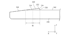
340 底部
342 載置部
344 ガイド部
350 係止部
352 頂部
354、356 傾斜部
358 係止面
360 前部
370 突部
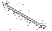
400 シェル
410 上部
412 押さえ部
414 当接部
420 下部
422 端子
430 側部
440 ホールドダウン
442 固定部
446 圧入部
500 アクチュエータ
510 操作部
520 押上げ部
530 回動軸
540 挟持部
550 収容部
570 突部(回動防止部)
Claims (10)
- 接点部及び被係止部を備え且つ板状又はシート状の対象物を、前端に有する挿入口から後方へ挿入されるコネクタであって、
コンタクトと、
係止部及び載置部を有し且つ前記コンタクトを保持するハウジングと、
前記対象物の前記挿入口への挿入が可能となる開位置と、前記挿入口に挿入された前記対象物の前記接点部と前記コンタクトとが接続される閉位置との間で回動可能となるように前記ハウジングに保持されるアクチュエータとを備え、
前記アクチュエータが前記開位置にあるとき、前記挿入口へ挿入された前記対象物の前記被係止部と前記係止部とが係止することにより、前記対象物の前方への移動が一時的に防止され、
前記アクチュエータが前記閉位置にあるとき、前記対象物は前記アクチュエータと前記載置部との間で挟持され、
前記アクチュエータが前記開位置にあるときに前記対象物の主面を前記載置部へ向けて押さえることにより前後方向に直交する上方への前記対象物の移動を一時的に防止する押さえ部を更に備えており、
前記ハウジングを少なくとも部分的に覆い、前記ハウジングと共に前記挿入口を規定するシェルを更に備え、
前記押さえ部は、前記シェルと一体に形成され前記シェルの前端から後斜め下方向に向かって前記挿入口内に延びている
コネクタ。 - 請求項1記載のコネクタであって、
前記係止部は、前記上方に突出するように前記載置部上に形成されている
コネクタ。 - 請求項2記載のコネクタであって、
前記係止部は、頂部と、前記頂部から前記載置部へ傾斜し前記対象物を前記頂部までガイドする傾斜部と、前記頂部よりも後方に形成され前記被係止部と当接する係止面とを有している
コネクタ。 - 請求項3記載のコネクタであって、
前記頂部は、前記係止部の前記前後方向における中点よりも後方に位置している
コネクタ。 - 請求項3又は請求項4記載のコネクタであって、
前記ハウジングは、前記対象物を前記挿入口へガイドするためのガイド部を有し、
前記傾斜部の傾斜角度は、前記ガイド部の傾斜角度と略等しくした
コネクタ。 - 請求項2乃至請求項5いずれか記載のコネクタであって、
前記押さえ部は、弾性を有し、且つ、前記対象物の前記主面に当接する当接部を備えており、
前記対象物が挿入されていない状態において、前記当接部と前記載置部との上下方向における距離は、前記対象物の厚さよりも小さい
コネクタ。 - 請求項2乃至請求項6いずれか記載のコネクタであって、
前記対象物上において、前記押さえ部により押圧される部位と前記アクチュエータ及び前記載置部により挟持される部位とは、前記前後方向及び上下方向の双方に直交する前記左右方向において一直線上に並んでいる
コネクタ。 - 請求項2乃至請求項5いずれか記載のコネクタであって、
前記係止部は、前記前後方向及び上下方向の双方に直交する左右方向において前記載置部の両端に形成されており、
前記被係止部は、前記対象物の前記左右方向における両端から内側に向かって凹む凹部の縁である
コネクタ。 - 請求項2乃至請求項8いずれか記載のコネクタであって、
前記係止部の前記載置部からの高さは、前記対象物の厚さよりも小さい
コネクタ。 - 請求項1乃至請求項9いずれか記載のコネクタであって、
前記アクチュエータは、前記閉位置において前記ハウジングと係止することにより意図しない前記開位置への回動を防ぐ回動防止部を更に有している
コネクタ。
Priority Applications (4)
| Application Number | Priority Date | Filing Date | Title |
|---|---|---|---|
| JP2011191893A JP5826568B2 (ja) | 2011-09-02 | 2011-09-02 | コネクタ |
| TW101129462A TWI515976B (zh) | 2011-09-02 | 2012-08-15 | 連接器 |
| KR1020120091001A KR101366052B1 (ko) | 2011-09-02 | 2012-08-21 | 커넥터 |
| CN201210319810.4A CN102983457B (zh) | 2011-09-02 | 2012-08-31 | 连接器 |
Applications Claiming Priority (1)
| Application Number | Priority Date | Filing Date | Title |
|---|---|---|---|
| JP2011191893A JP5826568B2 (ja) | 2011-09-02 | 2011-09-02 | コネクタ |
Publications (3)
| Publication Number | Publication Date |
|---|---|
| JP2013054886A JP2013054886A (ja) | 2013-03-21 |
| JP2013054886A5 JP2013054886A5 (ja) | 2014-08-14 |
| JP5826568B2 true JP5826568B2 (ja) | 2015-12-02 |
Family
ID=47857283
Family Applications (1)
| Application Number | Title | Priority Date | Filing Date |
|---|---|---|---|
| JP2011191893A Active JP5826568B2 (ja) | 2011-09-02 | 2011-09-02 | コネクタ |
Country Status (4)
| Country | Link |
|---|---|
| JP (1) | JP5826568B2 (ja) |
| KR (1) | KR101366052B1 (ja) |
| CN (1) | CN102983457B (ja) |
| TW (1) | TWI515976B (ja) |
Families Citing this family (5)
| Publication number | Priority date | Publication date | Assignee | Title |
|---|---|---|---|---|
| TWM462465U (zh) * | 2013-03-29 | 2013-09-21 | Tarng Yu Entpr Co Ltd | 連接器組合及電連接器 |
| JP6437182B2 (ja) * | 2013-05-17 | 2018-12-12 | 日本航空電子工業株式会社 | 電気コネクタ |
| JP6293634B2 (ja) | 2014-10-03 | 2018-03-14 | 日本航空電子工業株式会社 | コネクタ |
| KR101690160B1 (ko) * | 2015-05-22 | 2016-12-28 | (주)우주일렉트로닉스 | 가압부를 구비하는 커넥터 장치 |
| JP6053980B2 (ja) * | 2016-07-07 | 2016-12-27 | 京セラコネクタプロダクツ株式会社 | ケーブル用コネクタ |
Family Cites Families (11)
| Publication number | Priority date | Publication date | Assignee | Title |
|---|---|---|---|---|
| JPH1174043A (ja) * | 1997-08-29 | 1999-03-16 | Molex Inc | 平型柔軟ケーブル用コネクタとケーブルの接続構造 におけるロック構造 |
| JP2001266978A (ja) * | 2000-03-22 | 2001-09-28 | Shoji Kinoshita | フラットケーブル用コネクタ |
| JP4044939B2 (ja) * | 2005-03-24 | 2008-02-06 | イリソ電子工業株式会社 | コネクタ |
| JP2008226524A (ja) * | 2007-03-09 | 2008-09-25 | Kyocera Elco Corp | コネクタ |
| KR100951073B1 (ko) * | 2007-03-22 | 2010-04-05 | 주식회사 후성테크 | 플렉시블 케이블 커넥터 |
| JP4548803B2 (ja) * | 2008-04-24 | 2010-09-22 | ヒロセ電機株式会社 | 平型導体用電気コネクタ |
| JP5016635B2 (ja) * | 2009-06-02 | 2012-09-05 | 日本航空電子工業株式会社 | コネクタ |
| KR101107455B1 (ko) * | 2009-11-04 | 2012-01-19 | 한국몰렉스 주식회사 | 양면 연성회로케이블용 커넥터 |
| JP5501788B2 (ja) * | 2010-02-17 | 2014-05-28 | 第一電子工業株式会社 | コネクタ |
| KR101120908B1 (ko) * | 2010-04-27 | 2012-02-27 | 한국몰렉스 주식회사 | 연성 회로케이블용 커넥터 |
| JP5362765B2 (ja) * | 2011-04-19 | 2013-12-11 | 京セラコネクタプロダクツ株式会社 | コネクタ |
-
2011
- 2011-09-02 JP JP2011191893A patent/JP5826568B2/ja active Active
-
2012
- 2012-08-15 TW TW101129462A patent/TWI515976B/zh active
- 2012-08-21 KR KR1020120091001A patent/KR101366052B1/ko active IP Right Grant
- 2012-08-31 CN CN201210319810.4A patent/CN102983457B/zh active Active
Also Published As
| Publication number | Publication date |
|---|---|
| JP2013054886A (ja) | 2013-03-21 |
| KR101366052B1 (ko) | 2014-02-21 |
| TW201330387A (zh) | 2013-07-16 |
| CN102983457B (zh) | 2015-10-07 |
| KR20130025810A (ko) | 2013-03-12 |
| CN102983457A (zh) | 2013-03-20 |
| TWI515976B (zh) | 2016-01-01 |
Similar Documents
| Publication | Publication Date | Title |
|---|---|---|
| JP5943774B2 (ja) | コネクタ | |
| US8616906B2 (en) | Flexible printed circuit connector | |
| JP6452393B2 (ja) | コネクタ | |
| JP5645312B2 (ja) | コネクタ | |
| TWI552447B (zh) | 連接器 | |
| JP6840874B2 (ja) | 電気コネクタ | |
| US20120238125A1 (en) | Electric connector | |
| JP5826568B2 (ja) | コネクタ | |
| JP5634179B2 (ja) | 保持部材及び組立体 | |
| US9225097B2 (en) | Electrical connector having a guard portion | |
| JP5460037B2 (ja) | 電線対基板コネクタ | |
| US7494361B2 (en) | Card edge connector | |
| JP5102858B2 (ja) | コネクタ | |
| KR101531609B1 (ko) | 커넥터 | |
| JP2013098025A (ja) | コネクタ | |
| JP5016695B2 (ja) | コネクタ | |
| CN109478746B (zh) | 连接器 | |
| US20180034174A1 (en) | Electrical connector for flat conductor | |
| JP5905671B2 (ja) | 電気コネクタ | |
| JP4800404B2 (ja) | 電気コネクタ | |
| JP6533151B2 (ja) | コネクタ | |
| US9281593B2 (en) | Connector which is reduced in possibility of damage due to warping of a connection object without decreasing the insertability of the connection object | |
| JP5039161B2 (ja) | コネクタ | |
| JP5391295B2 (ja) | コネクタ | |
| JP6391746B1 (ja) | 平型導体用コネクタ |
Legal Events
| Date | Code | Title | Description |
|---|---|---|---|
| A521 | Request for written amendment filed |
Free format text: JAPANESE INTERMEDIATE CODE: A523 Effective date: 20140701 |
|
| A621 | Written request for application examination |
Free format text: JAPANESE INTERMEDIATE CODE: A621 Effective date: 20140701 |
|
| A131 | Notification of reasons for refusal |
Free format text: JAPANESE INTERMEDIATE CODE: A131 Effective date: 20150312 |
|
| A977 | Report on retrieval |
Free format text: JAPANESE INTERMEDIATE CODE: A971007 Effective date: 20150318 |
|
| A521 | Request for written amendment filed |
Free format text: JAPANESE INTERMEDIATE CODE: A523 Effective date: 20150423 |
|
| TRDD | Decision of grant or rejection written | ||
| A01 | Written decision to grant a patent or to grant a registration (utility model) |
Free format text: JAPANESE INTERMEDIATE CODE: A01 Effective date: 20150916 |
|
| A61 | First payment of annual fees (during grant procedure) |
Free format text: JAPANESE INTERMEDIATE CODE: A61 Effective date: 20151014 |
|
| R150 | Certificate of patent or registration of utility model |
Ref document number: 5826568 Country of ref document: JP Free format text: JAPANESE INTERMEDIATE CODE: R150 |
|
| R250 | Receipt of annual fees |
Free format text: JAPANESE INTERMEDIATE CODE: R250 |
|
| R250 | Receipt of annual fees |
Free format text: JAPANESE INTERMEDIATE CODE: R250 |
|
| R250 | Receipt of annual fees |
Free format text: JAPANESE INTERMEDIATE CODE: R250 |
|
| R250 | Receipt of annual fees |
Free format text: JAPANESE INTERMEDIATE CODE: R250 |
|
| R250 | Receipt of annual fees |
Free format text: JAPANESE INTERMEDIATE CODE: R250 |
|
| R250 | Receipt of annual fees |
Free format text: JAPANESE INTERMEDIATE CODE: R250 |