JP5755755B2 - Variable clutch mechanism and correction tape dispenser having variable clutch mechanism - Google Patents
Variable clutch mechanism and correction tape dispenser having variable clutch mechanism Download PDFInfo
- Publication number
- JP5755755B2 JP5755755B2 JP2013547460A JP2013547460A JP5755755B2 JP 5755755 B2 JP5755755 B2 JP 5755755B2 JP 2013547460 A JP2013547460 A JP 2013547460A JP 2013547460 A JP2013547460 A JP 2013547460A JP 5755755 B2 JP5755755 B2 JP 5755755B2
- Authority
- JP
- Japan
- Prior art keywords
- reel
- clutch mechanism
- take
- shaft
- correction tape
- Prior art date
- Legal status (The legal status is an assumption and is not a legal conclusion. Google has not performed a legal analysis and makes no representation as to the accuracy of the status listed.)
- Expired - Fee Related
Links
Images


Classifications
-
- B—PERFORMING OPERATIONS; TRANSPORTING
- B65—CONVEYING; PACKING; STORING; HANDLING THIN OR FILAMENTARY MATERIAL
- B65H—HANDLING THIN OR FILAMENTARY MATERIAL, e.g. SHEETS, WEBS, CABLES
- B65H37/00—Article or web delivery apparatus incorporating devices for performing specified auxiliary operations
- B65H37/002—Web delivery apparatus, the web serving as support for articles, material or another web
- B65H37/005—Hand-held apparatus
- B65H37/007—Applicators for applying coatings, e.g. correction, colour or adhesive coatings
-
- B—PERFORMING OPERATIONS; TRANSPORTING
- B33—ADDITIVE MANUFACTURING TECHNOLOGY
- B33Y—ADDITIVE MANUFACTURING, i.e. MANUFACTURING OF THREE-DIMENSIONAL [3-D] OBJECTS BY ADDITIVE DEPOSITION, ADDITIVE AGGLOMERATION OR ADDITIVE LAYERING, e.g. BY 3-D PRINTING, STEREOLITHOGRAPHY OR SELECTIVE LASER SINTERING
- B33Y80/00—Products made by additive manufacturing
-
- Y—GENERAL TAGGING OF NEW TECHNOLOGICAL DEVELOPMENTS; GENERAL TAGGING OF CROSS-SECTIONAL TECHNOLOGIES SPANNING OVER SEVERAL SECTIONS OF THE IPC; TECHNICAL SUBJECTS COVERED BY FORMER USPC CROSS-REFERENCE ART COLLECTIONS [XRACs] AND DIGESTS
- Y10—TECHNICAL SUBJECTS COVERED BY FORMER USPC
- Y10T—TECHNICAL SUBJECTS COVERED BY FORMER US CLASSIFICATION
- Y10T156/00—Adhesive bonding and miscellaneous chemical manufacture
- Y10T156/12—Surface bonding means and/or assembly means with cutting, punching, piercing, severing or tearing
- Y10T156/1348—Work traversing type
- Y10T156/1365—Fixed cutter
-
- Y—GENERAL TAGGING OF NEW TECHNOLOGICAL DEVELOPMENTS; GENERAL TAGGING OF CROSS-SECTIONAL TECHNOLOGIES SPANNING OVER SEVERAL SECTIONS OF THE IPC; TECHNICAL SUBJECTS COVERED BY FORMER USPC CROSS-REFERENCE ART COLLECTIONS [XRACs] AND DIGESTS
- Y10—TECHNICAL SUBJECTS COVERED BY FORMER USPC
- Y10T—TECHNICAL SUBJECTS COVERED BY FORMER US CLASSIFICATION
- Y10T156/00—Adhesive bonding and miscellaneous chemical manufacture
- Y10T156/17—Surface bonding means and/or assemblymeans with work feeding or handling means
- Y10T156/1788—Work traversing type and/or means applying work to wall or static structure
- Y10T156/1795—Implement carried web supply
-
- Y—GENERAL TAGGING OF NEW TECHNOLOGICAL DEVELOPMENTS; GENERAL TAGGING OF CROSS-SECTIONAL TECHNOLOGIES SPANNING OVER SEVERAL SECTIONS OF THE IPC; TECHNICAL SUBJECTS COVERED BY FORMER USPC CROSS-REFERENCE ART COLLECTIONS [XRACs] AND DIGESTS
- Y10—TECHNICAL SUBJECTS COVERED BY FORMER USPC
- Y10T—TECHNICAL SUBJECTS COVERED BY FORMER US CLASSIFICATION
- Y10T156/00—Adhesive bonding and miscellaneous chemical manufacture
- Y10T156/18—Surface bonding means and/or assembly means with handle or handgrip
Description
本開示は、クラッチ機構に関し、より端的には、クラッチ機構を有する修正テープディスペンサに関する。 The present disclosure relates to a clutch mechanism, and more particularly, to a correction tape dispenser having a clutch mechanism.
修正テープディスペンサは、誤記又はタイプミスを含む、紙のシートといった基材上に為された誤りの被覆のために使用可能である。汎用の例においては、修正テープディスペンサが筐体を含み、この内部には繰出リールおよび巻取リールが配置される。搬送リボンは、繰出リールに巻かれた第1端、及び巻取リールに巻かれた第2の端を有する。搬送リボンの片側は、基材上の誤りを被覆するために使用される修正コーティングで被覆される。クラッチ機構を介して巻取リールを駆動するように繰出リールが結合し、共通軸周りに回転する繰出および巻取リールを有する幾つかの既知の修正テープディスペンサがある。 The correction tape dispenser can be used to cover errors made on a substrate, such as a sheet of paper, including errors or typographical errors. In a general-purpose example, the correction tape dispenser includes a housing, and a supply reel and a take-up reel are disposed therein. The transport ribbon has a first end wound on the supply reel and a second end wound on the take-up reel. One side of the transport ribbon is coated with a correction coating that is used to cover errors on the substrate. There are several known correction tape dispensers that have a pay-out and take-up reel that is coupled to the take-up reel to drive the take-up reel through a clutch mechanism and rotates about a common axis.
前縁部を有する台部を有するアプリケータ先端が筐体に取付けられ、その前縁部が筐体の外側になる。アプリケータ先端が、搬送リボンから紙への修正コーティングの転写をアシストする。 An applicator tip having a base having a front edge is attached to the housing, and the front edge is outside the housing. The applicator tip assists in transferring the correct coating from the transport ribbon to the paper.
使用中、消費者の手で筐体を保持可能である。繰出リールから巻取リールへの搬送に関して、搬送リボンがアプリケータ先端に向けられ、台部を横切り、前縁部を回り、そして、巻取リールに戻る。アプリケータ先端の前縁部がリボン中に鋭い屈曲を生じさせ、修正コーティングがリボンから剥離するのを補助する。前縁部が、紙のシート又は他の基材の表面に対して搬送リボンを押し当て、修正コーティングを搬送リボンから紙上に転写し、その上の誤りを被覆し、かつ誤りの修正を支援する。 During use, the housing can be held by the consumer's hand. For transport from the supply reel to the take-up reel, the transport ribbon is directed toward the applicator tip, traverses the platform, travels around the front edge, and returns to the take-up reel. The leading edge of the applicator tip causes a sharp bend in the ribbon, helping the corrective coating peel from the ribbon. The leading edge presses the transport ribbon against the surface of the sheet of paper or other substrate, transfers the correction coating from the transport ribbon onto the paper, covers the errors thereon, and assists in correcting the errors .
前縁部が紙の端から端に移動するに応じて、真新しい修正コーティングを有する搬送リボンが繰出リールから引き出され、他方、巻取リールが駆動され、前縁部の上を通過してそれ故に修正コーティングが引き離された搬送リボンが巻き取られる。従って、修正コーティングの直線連続ストリップが紙面上に置かれ、その後、アプリケータ先端の前進運動が停止し、その先端が紙から離れるように持ち上げられる。 As the leading edge moves from one end of the paper to the other, the transport ribbon with a brand new correction coating is pulled out of the supply reel, while the take-up reel is driven and passes over the leading edge and hence The transport ribbon from which the correction coating has been pulled off is wound up. Thus, a straight continuous strip of corrective coating is placed on the paper, after which the forward movement of the applicator tip stops and the tip is lifted away from the paper.
そのような修正テープディスペンサにおいては、修正テープを基材に転写するのに要求される引く力が製品の使用期間に亘り着実に増大し、他方、修正テープを繰出リールから引き出すのに要求されるトルクが実質的に一定であることが良く知られている。トルクは、引く力を繰出リールに保管されている修正テープの半径で乗算したものに等しい。修正テープの供給が減少するに応じて繰出リールの半径が減少することが直ぐに理解できる。従って、一定のトルクを維持するために、修正テープにかかる引く力がテープの半径の減少を補完するべく増加しなければならない。 In such correction tape dispensers, the pulling force required to transfer the correction tape to the substrate steadily increases over the life of the product while it is required to pull the correction tape from the supply reel. It is well known that the torque is substantially constant. The torque is equal to the pulling force multiplied by the radius of the correction tape stored on the supply reel. It can be readily seen that the radius of the supply reel decreases as the correction tape supply decreases. Therefore, in order to maintain a constant torque, the pulling force on the correction tape must be increased to compensate for the tape radius reduction.
開示の可変式クラッチ機構は、テープ転写製品の操出リールから巻取リールへのテープの供給の移動に要求されるユーザーの労力の大きさを有利に調整し、例えば、他方、テープ転写製品の使用期間に亘る供給及び巻取リールの回転速度の適合も促進し、従ってよりユーザーフレンドリーな使用感を提供できる。 The disclosed variable clutch mechanism advantageously adjusts the amount of user effort required to move the tape supply from the reel to the take-up reel of the tape transfer product, for example, It also facilitates adapting the supply and take-up reel rotation speed over the period of use, thus providing a more user-friendly feel.
本開示の一側面が、第1リール、第2リール、付勢部材、及び摩擦部材を含むクラッチ機構を提供する。第1リールが、第1シャフトに回転可能に設けられる。第2リールが、第2シャフトに回転可能に設けられる。付勢部材が、第1リールと第1シャフトの間に設けられ、前記第1リールが第1位置及び少なくとも第2位置の間で前記第1シャフトに対して半径方向に可動であり、前記付勢部材が前記第1リールを前記第1位置へ付勢する。摩擦部材が第2リールにより支持されて第1リールの表面に接触し、摩擦部材が、第1リールが第1位置にある時に第1リール及び第2リールの間に第1摩擦力を生じさせ、第1リールが第2位置にある時に第1リール及び第2リールの間に第2摩擦力を生じさせる。 One aspect of the present disclosure provides a clutch mechanism including a first reel, a second reel, a biasing member, and a friction member. A first reel is rotatably provided on the first shaft. A second reel is rotatably provided on the second shaft. An urging member is provided between the first reel and the first shaft, the first reel is movable in a radial direction with respect to the first shaft between a first position and at least a second position, A biasing member biases the first reel to the first position. The friction member is supported by the second reel and contacts the surface of the first reel, and the friction member generates a first friction force between the first reel and the second reel when the first reel is in the first position. When the first reel is in the second position, a second friction force is generated between the first reel and the second reel.
本開示の別の側面が、筐体、アプリケータヘッド、第1リール、第2リール、付勢部材、及び摩擦部材を含むテープディスペンサを提供する。アプリケータヘッドが筐体により支持される。筐体内で第1リールが第1シャフトに回転可能に設けられる。筐体内で第2リールが第2シャフトに回転可能に設けられる。付勢部材が第1リール及び第1シャフトの間に設けられ、第1リールが、第1位置及び少なくとも第2位置の間で第1シャフトに対して半径方向に可動であり、付勢部材が、操出リールを第1位置へ付勢する。摩擦部材が第2リールにより支持され、第1リールの表面に接触し、摩擦部材が、第1リールが第1位置にある時に第1リール及び第2リールの間に第1摩擦力を生じさせ、第1リールが第2位置にある時に第1リール及び第2リールの間に第2摩擦力を生じさせる。 Another aspect of the present disclosure provides a tape dispenser that includes a housing, an applicator head, a first reel, a second reel, a biasing member, and a friction member. An applicator head is supported by the housing. A first reel is rotatably provided on the first shaft within the housing. A second reel is rotatably provided on the second shaft within the housing. A biasing member is provided between the first reel and the first shaft, the first reel is movable in a radial direction relative to the first shaft between the first position and at least the second position, and the biasing member is The biasing reel is urged to the first position. The friction member is supported by the second reel, contacts the surface of the first reel, and the friction member generates a first friction force between the first reel and the second reel when the first reel is in the first position. When the first reel is in the second position, a second friction force is generated between the first reel and the second reel.
本開示のまた別の側面が、筐体、操出リール、巻取リール、搬送リボン、付勢部材、及びOリングを含む修正テープディスペンサを提供する。筐体が、アプリケータヘッド、供給シャフト、及び供給シャフトに平行に離間した巻取シャフトを支持する。操出リールが供給シャフトに回転可能に設けられ、駆動面を画定する。巻取リールが、操出リールに隣接して巻取シャフトに回転可能に設けられる。搬送リボンが、修正テープの供給を搬送し、また操出リールからアプリケータヘッドを回り巻取リールへ延在する。付勢部材が操出リールにより支持され、操出リール及び供給シャフトの間の位置において供給シャフトに同心に周囲に設けられる。更には、付勢部材が供給シャフトに回転可能に設けられ、第1位置及び少なくとも第2位置の間で供給シャフトに対して半径方向に操出リールの移動を促進するように変形可能であり、ここで、付勢部材が、操出リールを第1位置へ付勢する。Oリングが、巻取リールにより支持され、また同心に周囲に配置される。更には、Oリングが、操出リールの駆動面に接触し、Oリングが、繰出リールが第1位置にある時に繰出リール及び巻取リールの間に第1摩擦力を生じさせる第1圧縮状態を取り、繰出リールが第2位置にある時に繰出リール及び巻取リールの間に第2摩擦力を生じさせる第2圧縮状態を取る。 Yet another aspect of the present disclosure provides a correction tape dispenser that includes a housing, a steering reel, a take-up reel, a transport ribbon, a biasing member, and an O-ring. A housing supports an applicator head, a supply shaft, and a take-up shaft spaced parallel to the supply shaft. A steering reel is rotatably mounted on the supply shaft and defines a drive surface. A take-up reel is rotatably provided on the take-up shaft adjacent to the steering reel. A transport ribbon transports the supply of correction tape and extends from the drive reel around the applicator head to the take-up reel. The biasing member is supported by the steering reel and is provided concentrically around the supply shaft at a position between the steering reel and the supply shaft. Furthermore, a biasing member is rotatably provided on the supply shaft and is deformable to facilitate movement of the steering reel in a radial direction relative to the supply shaft between a first position and at least a second position, Here, the biasing member biases the operation reel to the first position. An O-ring is supported by the take-up reel and is arranged concentrically around it. Furthermore, the O-ring contacts the drive surface of the operation reel, and the O-ring generates a first friction force between the supply reel and the take-up reel when the supply reel is in the first position. And the second compression state in which the second frictional force is generated between the supply reel and the take-up reel when the supply reel is at the second position.
本開示のまた更なる側面が、第1リール、第2リール、及び摩擦部材を含むクラッチ機構を提供する。第1リールが第1シャフトに回転可能に設けられる。第2リールが第2シャフトに回転可能に設けられ、第1シャフトから離間して平行に設けられる。摩擦部材が、第2リールにより支持され、また同心に周囲に設けられ、摩擦部材の少なくとも一部が、第1リール及び第2リールの間に接触して設けられ、これらの間に摩擦力を生じさせる。 A still further aspect of the present disclosure provides a clutch mechanism that includes a first reel, a second reel, and a friction member. A first reel is rotatably provided on the first shaft. A second reel is rotatably provided on the second shaft, and is provided in parallel with being spaced from the first shaft. The friction member is supported by the second reel and is provided concentrically around the friction member, and at least a part of the friction member is provided in contact between the first reel and the second reel. Cause it to occur.
本開示のまた更なる側面が、筐体、アプリケータヘッド、操出リール、巻取リール、及び摩擦部材を含むテープディスペンサを提供する。筐体が、供給シャフト及び供給シャフトに平行に離間した巻取シャフトを支持し、アプリケータヘッドが筐体により支持される。操出リールが筐体内で供給シャフトに回転可能に設けられ、アプリケータヘッドにより基材に対して貼られるように適合したマーキングテープを搬送する搬送リボンを含むテープの供給源を支持するように適合される。巻取リールが筐体内で巻取シャフトに回転可能に設けられる。巻取リールは、マーキングテープが基材に転写された後に搬送リボンを回収するためのものである。摩擦部材が、巻取リールにより支持され、また同心に周囲に設けられ、摩擦部材の少なくとも一部が、操出リール及び巻取リールの間に設けられ、これらの間に摩擦力を生じさせる。 Yet a further aspect of the present disclosure provides a tape dispenser that includes a housing, an applicator head, a steering reel, a take-up reel, and a friction member. The housing supports the supply shaft and the take-up shaft spaced parallel to the supply shaft, and the applicator head is supported by the housing. A steering reel is rotatably mounted on the supply shaft within the housing and is adapted to support a tape supply including a transport ribbon that transports a marking tape adapted to be applied to a substrate by an applicator head Is done. A take-up reel is rotatably provided on the take-up shaft within the housing. The take-up reel is for collecting the transport ribbon after the marking tape is transferred to the substrate. The friction member is supported by the take-up reel and is provided concentrically around the friction member, and at least a part of the friction member is provided between the operation reel and the take-up reel and generates a friction force therebetween.
本開示のまた更なる側面が、筐体、操出リール、巻取リール、搬送リボン、及びOリングを含む修正テープディスペンサを提供する。筐体が、アプリケータヘッド、供給シャフト、供給シャフトから離間し平行に設けられた巻取シャフトを支持する。操出リールが供給シャフトに回転可能に設けられ、駆動面を画定する。巻取リールが操出リールに隣接して巻取シャフトに回転可能に設けられる。搬送リボンの少なくとも一部が、修正テープの供給を搬送し、また搬送リボンが、操出リールからアプリケータヘッドを回り巻取リールへ延在する。Oリングが、巻取リールにより支持され、また同心に周囲に設けられる。Oリングの少なくとも一部が、巻取リールと操出リールの駆動面の間に接触して設けられ、Oリングが操出リール及び巻取リールの間に摩擦力を生じさせる。 Yet a further aspect of the present disclosure provides a correction tape dispenser that includes a housing, a steering reel, a take-up reel, a transport ribbon, and an O-ring. The housing supports the applicator head, the supply shaft, and a take-up shaft provided in parallel with the supply shaft. A steering reel is rotatably mounted on the supply shaft and defines a drive surface. A take-up reel is rotatably provided on the take-up shaft adjacent to the steering reel. At least a portion of the transport ribbon transports the supply of correction tape, and the transport ribbon extends from the drive reel around the applicator head to the take-up reel. An O-ring is supported by the take-up reel and is provided concentrically around it. At least a part of the O-ring is provided in contact between the drive surface of the take-up reel and the take-out reel, and the O-ring generates a frictional force between the take-out reel and the take-up reel.
本開示は、可変式クラッチ機構、及び可変式クラッチ機構を含む修正テープディスペンサに関し、修正テープの一貫した転写を確実にするのに役立つ。本明細書に記述される可変式クラッチ機構は、修正テープディスペンサでの使用に限定されず、むしろ、その機能面から利益を得る任意の他の装置に用いられ得ることが予測でき、限定するわけではないが、例えば、蛍光「ハイライター」型テープ又は両面接着テープの転写用の機構といった他の転写テープ機構を含む。開示の可変式クラッチ機構は、製品の使用期間に亘る修正テープの転写に要求される引く力の差異を有利に低減し、好ましくは、製品の使用期間に亘る修正(又は他の)テープの基材への転写に実質的に同一の引く力の利用を促し、これにより、装置をより使い勝手良くし、また製品の使用期間に亘ってより一貫したものにできる。加えて、可変式クラッチ機構が、繰出リールに対する巻取リールの回転速度を自動的に調整し、テープリボンが繰出リールから円滑に送られることが確保され、修正テープリボン及び/又は搬送リボンに過大又は過小の張力を生じさせる事無くして搬送リボンが巻取リールにより回収され、これによって、伸び、裂け、及び/又はルーピングといった動作上の不整合性が回避される。 The present disclosure relates to a variable clutch mechanism and a correction tape dispenser including the variable clutch mechanism, which helps to ensure consistent transfer of the correction tape. The variable clutch mechanism described herein is not limited to use with a correction tape dispenser, but rather can be predicted and limited to be used with any other device that would benefit from its functionality. However, it includes other transfer tape mechanisms such as, for example, a fluorescent “highlighter” type tape or a double-sided adhesive tape transfer mechanism. The disclosed variable clutch mechanism advantageously reduces the difference in pulling force required to transfer the correction tape over the life of the product, and preferably the base of the correction (or other) tape over the life of the product. It encourages the use of substantially the same pulling force for transfer to the material, which makes the device more usable and more consistent over the life of the product. In addition, the variable clutch mechanism automatically adjusts the rotation speed of the take-up reel with respect to the supply reel, ensuring that the tape ribbon is smoothly fed from the supply reel, and overloading the correction tape ribbon and / or the transport ribbon. Alternatively, the transport ribbon can be collected by the take-up reel without creating too little tension, thereby avoiding operational inconsistencies such as stretching, tearing, and / or looping.
図1及び2は、本開示の原理に従って組み立てられ、また可変式クラッチ機構100(図4A〜4Cに概略的に図示する)を含む修正テープディスペンサ10の一つの実施形態を図示する。概して、修正テープディスペンサ10は、筐体12、操出リール14、巻取リール16、アプリケータヘッド18、及び修正テープリボン20の供給源を含む。図示の形態においては、操出リール14が、巻取リール16及びアプリケータヘッド18の間に設けられ、巻取リール16がアプリケータヘッド18から操出リール14の反対に設けられる。換言すれば、操出リール14が巻取リール16よりもアプリケータヘッド18に近接して設けられ、これは同様の従来設計の修正テープディスペンサとは対照的である。筐体12は、操出リール14を回転可能に支持する供給シャフト22a、及び巻取リール16を回転可能に支持する巻取シャフト22bを含む。加えて、図1に図示のように、例えば、筐体12が、後述のようにテープディスペンサ10の動作中に修正テープ20を案内するための一組のガイドポスト13a、13bを含む。開示の実施形態においては、供給及び巻取シャフト22a、22bが、図示のように、筐体12に対する位置に固定され、互いに離間され、また互いに実質的に平行である。
1 and 2 illustrate one embodiment of a
筐体12は、例えば、スナップされ又は別の方法で一緒に連結してディスペンサ10の他の構成要素を収容するキャビティーを画定する一組の筐体シェル12a、12b(図2及び3に示す)を含み得る点において概して従来通りである。本実施形態の修正テープディスペンサ10の供給及び巻取リール14、16が円筒又は円筒形状の部材を概して含み、各々、回転変位のために供給及び巻取シャフト22a、22bに配置される。アプリケータヘッド18は、筐体12に固定され、かつ転写端24を含む任意の従来のアプリケータヘッドに類似する。修正テープリボン20は、長い搬送リボン20aと、搬送リボン20aに結合した長い修正テープ20bを備える。修正テープリボン20は、操出リール14から延び、ガイドポスト13a、13bの間を延び、アプリケータヘッド18の転写端24を回り、ガイドポスト13a、13bの間に戻り、操出リール14により送られる修正テープリボン20の供給源の任意の残部上を延び、そして巻取リール16へ延びる。
The
動作中、ユーザーがアプリケータヘッド18の転写端24を例えば紙片といった基材に対して押圧し、アプリケータヘッド18から離れる方向へ修正テープディスペンサ10を移動させる。搬送リボン20aにより搬送される修正テープ20bが基材に対して接着するように設定される。従って、修正テープディスペンサ10の上述の動作が、図1に示すように、引く力Fを付与し若しくは変換され、これにより操出リール14から修正テープリボン20が引かれる。この動作により修正テープ20bの転写のための筐体12からの修正テープリボン20の分配が生じ、それが搬送リボン20aから剥離して基材に接着する。次に、使用済みの搬送リボン20aが、巻取リール16により収集される。
In operation, the user presses the
上述のように、操出リール14から離れるように修正テープリボン20を引くのに要求される引く力Fが、製品の使用期間に亘って着実に増大する。操出リール14から修正テープリボン20を引いて離すのに要求されるトルクが実質的に一定であり、他方、操出リール14上の修正テープリボン20の半径Rが減少するため、引く力Fが増加する。実質的に一定のトルクが維持され、修正テープリボン20が一貫した態様で操出リール14から引かれて離れる。従って、操出リール14上の修正テープリボン20の供給源が漸減し始めると、従来の修正テープディスペンサのユーザーは、より大きい引く力Fを修正テープリボン20にかけなければならない。しかしながら、本開示の実施形態の修正テープディスペンサ10は、可変式クラッチ機構100を含み、後述のように、この現象の負の効果を低減する。
As described above, the pulling force F required to pull the
図3は、可変式クラッチ機構100を含む、図1及び2の修正テープディスペンサを分解斜視図で図示する。可変式クラッチ機構100は、操出リール14、巻取リール16、付勢部材102、及び摩擦部材104を含む。これらの各構成部品は、プラスチック材料、金属材料、複合材料、又は意図された目的に適う任意の他の材料から構成できる。
FIG. 3 illustrates the modified tape dispenser of FIGS. 1 and 2 in an exploded perspective view, including the variable
操出リール14は、供給円筒106及び駆動輪108を含む。供給円筒106が、外面106a及び内面106bを画定する中空の円筒を構成する。駆動輪108は、駆動リム109及び複数のスポーク110を含む。駆動リム109が供給円筒106の直径よりも大きい直径を有し、そのため、スポーク110が駆動リム109から径方向内側に延び、供給円筒106の軸方向の端部に隣接する供給円筒106の外面106aに接続される。そのように、供給円筒106及び駆動輪108が、一体の構成部品として図示される。駆動輪108がリム109及びスポーク110を含むように図示されたが、代替の実施形態においては、駆動輪108が、中実のディスク状の構造、又は意図する目的に適う任意の他の構造を含むことができる。既に述べたように、駆動輪108の供給円筒106が中空であり、外面106a及び内面106bを定める。供給円筒106の外面106aが、図1及び2に図示のように修正テープ20の供給源を支持するように適合される。供給円筒106の内面106bが付勢部材102を収容するように適合され、これが供給シャフト22aを受容し、次に筐体12の供給シャフト22a上の操出リール14を支持する。
The
例えば、図1及び2に示すように、付勢部材102が、操出リール14と供給シャフト22aの径方向の間の位置において供給シャフト22aに回転可能に設けられるように適合される。後述のように、例えば、修正テープディスペンサ10の動作中に供給シャフト22aに対する半径方向の操出リール14の移動を促進するため、一般的に、付勢部材102がバネといった弾性部材を含む。ある実施形態においては、付勢部材102が、約5N/mm〜約100N/mmの範囲内の剛性を有する。開示の実施形態においては、付勢部材102が、ハブ112及び複数の可撓性指部114を有する放射状スプリングの如く呼ぶことができる物を含む。ハブ112は、円筒部材を含み、外面112a及び内面112bを定める。ハブ112の内面112bが、回転可能な態様で筐体12の供給シャフト22aに直接接触して存在するように適合される。換言すれば、付勢部材102のハブ112が、図1及び2に示すように、筐体12の供給シャフト22aに回転可能に係合するように適合される。可撓性指部114がハブ112の外面112aから半径方向外側に延在し、各可撓性指部114が、ハブ112の外面112bに取付けられた近端部114aと、ハブ112からある距離だけ離間した遠端部114bを含む。
For example, as shown in FIGS. 1 and 2, the biasing
組み立てられると、図1及び2に示すように、例えば、付勢部材102が、操出リール14の供給円筒106の内部に配置され、1以上の可撓性指部114の遠端部114bが供給円筒106の内面106bに接触又は他の態様にて係合する。幾つかの実施形態においては、1以上の可撓性指部114の遠端部114bを供給円筒106の内面106bに接続可能である。例えば、開示の実施形態においては、各可撓性指部114の遠端部114bが突起116を含むように図示され、操出リール14の中央円筒106の内面106bが突起116を受容するための対応の複数の溝118を定める。そのように、組立に際しては、可撓性指部114の突起116が、溝118内に挿入されるように適合され、これにより、操出リール14の供給円筒106に対する付勢部材102の径方向の位置が固定される。可変式クラッチ機構100の図示の形態においては、可撓性指部114の突起116が、可撓性指部114に一体的に形成された概して中実の円筒状形状を含み、供給円筒106の溝118が対応する略円柱状の溝を含む。しかしながら、代替の実施形態においては、突起116及び溝118が、意図される目的に適う任意の幾何形状から概して形成され得る。例えば、ある実施形態においては、溝118の代わりに、操出リール104の中央円筒106が、付勢部材102の指部114の遠端部114bに接触する1以上の突起を規定し、内側の円筒106と付勢部材102の位置関係を維持する。
When assembled, as shown in FIGS. 1 and 2, for example, the biasing
図1及び3に示すように、付勢部材102の本実施形態の各可撓性指部114は、付勢部材102を側面から見る時に曲がった外形を有する実質的に2次元部材を含む。換言すれば、可撓性指部114の夫々がアーチ形状であり、例えば、板バネに類似する。従って、ここに開示された形態の付勢部材102を図1に提示された側面方向から見ると、例えば、可撓性指部114により付勢部材102が渦巻形状を持つ。このように構成されると、修正テープディスペンサ10又は可変式クラッチ機構が組み込まれた別の組立品の動作過程といったように半径方向に付与された力の影響の下で供給シャフト22aに対して可撓性指部114の夫々が半径方向に可撓するように適合され、操出リール14の全体が供給シャフト22aに対して半径方向に動くことができる。
As shown in FIGS. 1 and 3, each
また図3を参照すると、ここに開示した実施形態の巻取リール16が、内面120a及び外面120bを定める円筒部材120を含む。円筒部材120の内面120aが、回転可能な態様で筐体12の巻取シャフト22bに直接接触して存在するように適合される。換言すれば、巻取リール16の円筒部材120が、図1及び2に示すように、筐体12の巻取シャフト22bに回転可能に係合するように適合される。開示の実施形態においては、円筒部材102の外面120bが、円筒部材120の軸方向の端部に近接して設けられた環状溝122を定める。環状溝122は、摩擦部材104を受容するためのものであり、例えば、Oリングを含むことができる。そのように、開示の実施形態においては、摩擦部材104が、巻取リール16、より端的には、巻取リール16の円筒部材120により支持される。そのように、摩擦部材104が支持され、巻取リール16に同心に配置される。Oリングは、シリコーン又はゴムといった弾性材料を備えることができる。代替的に、フォーム材料から成るOリング又はワッシャを使用しても良い。上述の記述が別々の構成要素が一緒に組み立てられた摩擦部材104及び巻取リール16を含むが、代替の実施形態においては、摩擦部材104及び巻取リール16が共に成形される。Oリング又はワッシャを構成する部材の輪が、円形状の断面又は任意の断面を有することができる。Oリングとの用語は、いずれかの特定の断面形状のいずれかの特定の材料の輪に限定されるように意図されず、むしろ、意図される目的に適うように配置及び構成された単なる材料片と意図される。
Referring also to FIG. 3, the take-
テープディスペンサ10が上述のように構築されると、操出リール14が、筐体12の供給シャフト22aに回転可能に設けられるように適合され、巻取リール16が、筐体12の巻取シャフト22bに設けられるように適合される。図2に示すように、操出及び巻取リール14、16が各シャフト22a、22bに設けられる時、操出リール14の駆動輪108の駆動リム109が、巻取リール16の円筒部材120の外面120a上に支持された摩擦部材104と同一平面に配置される。そのように、摩擦部材104の少なくとも一部が、巻取リール16と操出リール14の間に配される。より端的には、摩擦部材104の少なくとも一部が、巻取リール16の円筒部材120と操出リール14の駆動輪108の駆動リム109の間に配される。図示のように、摩擦部材104が、駆動リム109の駆動面109aに接触点Cで接触し、垂直力Nをそこへ与える(図4A〜4Cに示す)。開示の実施形態においては、駆動面109aが、駆動リム109の半径方向外側に向いた面を含む。そのように構成され、操出リール14の回転変位が、この接触点Cを介して巻取リール16の回転変位へ伝達可能である。そのような回転変位がリール14、16の間で伝達される比率が駆動リム109と摩擦部材104の間の接触点Cで生成される摩擦の大きさに依存し、これ自体が垂直力Nの大きさに依存する。接触点Cでの垂直力Nの大きさが、可変式クラッチ機構100の動作、同様に摩擦部材104と駆動リム109の間の摩擦係数に依存し、例えば、これ自体が、摩擦部材104と駆動リム109の材質や寸法に依存する。幾つかの実施形態においては、摩擦部材104と駆動リム109の間の摩擦係数が、約0.1から約0.5の範囲、例えば、約0.35、約0.40、約0.45であり得る。この促進のため、摩擦部材104が、弾性又は圧縮性材料から構成され、ここで説明するように、約2N/mmから約50N/mmの範囲の剛性を有し得る。
When the
ここで図4A−4Cを参照して上述のテープディスペンサ10内に組み込まれた状態の可変式クラッチ機構100の動作を説明する。図4A−4Cは、本開示の原理に従って組み立てられ、上述のテープディスペンサ10内に含まれ得る可変式クラッチ機構100の一つの実施形態を概略的に図示する。可変式クラッチ機構100は、操出リール14、巻取リール16、付勢部材102、及び摩擦部材104を含む。
Here, the operation of the variable
既に図示及び説明のように、供給及び巻取リール14、16が、回転変位のため、各々、供給及び巻取シャフト22a、22bに設けられる。操出リール14が、供給円筒106の外面106a上の修正テープリボン20の供給源を保管する。巻取リール16が、円筒部材120の外面120a上の搬送リボン20aの使用済みの供給源を保管する。図4A−4Cに、様々な動作状態の可変式クラッチ機構100を図示する。図4Aが、静止状態にある機構100を図示し、ここで、操出リール14上の修正テープリボン20の供給源が半径R1を有する。図4Bは、初動状態の機構100を図示し、つまり、ここで、操出リール14が、図4Aに図示したものと同一の半径R1を有するように示された、相対的に大きな修正テープリボン20の供給源を含む。図4Cは、目減り動作状態の機構100を図示し、つまりは、ここで、操出リール14が、図4A及び4Bに図示された半径R1よりも小さい半径R2を有するように示された、修正テープリボン20のかなり減じられた供給源を含む。
As already shown and described, supply and take-up
図4Aに図示された静止状態においては、修正テープディスペンサ10が使用されておらず、従って、操出リール14から修正テープリボン20を引き出すために力Fが何ら加えられていない。従って、駆動リム109の軸に対応する供給円筒106の軸Aが、供給シャフト22aの軸A1に一直線に合致する。換言すれば、図4Aに図示した静止状態においては、操出リール14と供給シャフト22aが共通軸を共有する。
In the resting state illustrated in FIG. 4A, the
ユーザーが修正テープディスペンサ10の使用を開始する際、図1及び2を参照して上述のように、ユーザーが、操出リール14から修正テープリボン20の供給を引き出すために力Fを加える。ユーザーにより加えられた力Fが、操出リール14にトルクτを付与し、これが、修正テープリボン20の供給源の半径Rにより乗算される力Fの積を構成する。トルクτは、当初、図4A及び4Bの配向に関し、時計回りの方向に操出リール14を回転させる。そのような回転の過程においては、駆動リム109と摩擦部材104の間の接触点Cで生じた摩擦が、巻取リール16へ回転力を付与し、これにより、巻取リール16が、図4A−4Cの配向に関して半時計周りに回転し、これにより使用済みの搬送リボンを回収する。この初期動作状態の過程では、修正テープリボン20の供給源の半径R1が、巻取リール16上の使用済みの搬送リボン20aの回収部の半径rよりも大きい。操出リール14及び巻取リール16が従って異なる速度で回転するため、テープ20bの転写の過程の修正テープリボン20の過剰な張り又はループピングを避けるため、操出リール14が、巻取リール16に対して滑らなければならない。操出リール14に滑りを生じさせるのに要求されるユーザーの労力が、摩擦部材104により駆動リム109に与えられる垂直力Nの大きさに正比例に依存する。換言すれば、巻取リール16が操出リール14に対して回転する比率が、接触点Cで生じた摩擦の量に影響する垂直力Nの大きさに依存する。図4Cを参照して更にこれを図説する。
When the user begins to use the
図4Cは、修正テープリボン20の減じられた供給源の状態の修正テープディスペンサ10を概略的に図示する。端的には、上述のように、図4Cの操出リール14上の修正テープリボン20の供給源が、図4A及び4Bに図示した半径R1よりも小さい半径R2を有する。従って、操出リール14から修正テープリボン20を引き出すためにユーザーが操出リール14に力Fを付与すると、図4A及び4Bに図示した操出リール14に付与されたトルクτの大きさに類する大きさで操出リール14にトルクτを付与するために、付与力Fが顕著に増加しなければならない。付与力Fの増加の正比例の結果として、供給円筒106が受ける半径方向の荷重の量も増加し、図4Cに図示のように、これが付勢部材102に変形をもたらす。この変形により、付与された力Fの半径方向に供給円筒106が移動することが可能になり、これは図4Cの配向に関して左、巻取リール16及び関連の摩擦部材104から離れる方向である。力Fの方向に供給シャフト22aの軸A1から変位した供給円筒106の軸Aがこれを図4Cに図示する。すなわち、修正テープ20の供給源に力Fが付与されると、図4Cに示すように、供給円筒106が受ける半径方向の力により供給円筒106が可撓性指部114の部分を圧縮し、これが、続いて、巻取リール16から離れるように供給シャフト22aに対して供給円筒106が変位することを許容する。更には、供給円筒106が駆動輪108に固定されているため、供給円筒106のこの変位により駆動輪108の変位にも帰結し、より端的には、駆動リム109が摩擦部材104から離れるように変位し、これにより、摩擦部材104により駆動リム109に加えられる垂直力Nの大きさが減じられる。
FIG. 4C schematically illustrates the
従って、垂直力Nの大きさを減じることにより、例えば、図4Cの接触点Cの範囲も図4Bの接触点Cの範囲に比べて減じられる。この減じられた垂直力Nの大きさ及び減じられた接触点Cの範囲により、駆動リム109及び摩擦部材104の間の摩擦が減じられることに帰結する。有利なことに、この減じられた摩擦により、操出リール14が巻取リール16に対して滑ることが容易になり、修正テープの円滑な送りが確保される。すなわち、摩擦部材104により加えられる垂直力Nの大きさが操出リール14に支持された修正テープリボン20の量の関数として減少するため特に相対的に大きな付与力Fが付与される時、操出リール14が巻取リール16に対してより容易に滑ることが可能である。このように構成されると、図4Cにおいては、操出リール14が巻取リール16に対して滑り、これにより、修正テープリボン20を供給する操出リール14と実質的に同じ速度で使用済みの搬送リボン20aを回収する巻取リール16の能力が促進される。操出リール14から修正テープリボン20を引き出すために力Fの付与をユーザーが中断すると、付勢部材102が、その自然の形状(配置)に復帰し、また例えば図4Aに図示の静止状態に戻すように操出リール14を動かす。
Therefore, by reducing the magnitude of the normal force N, for example, the range of the contact point C in FIG. 4C is also reduced compared to the range of the contact point C in FIG. 4B. This reduced normal force N and reduced contact point C range result in reduced friction between the
上述の説明を踏まえると、摩擦部材104により生じる垂直力Nの大きさを変更することにより、操出リール14により支持された修正テープリボン20の量の関数として、操出リール14から修正テープリボン20を引き出すのに要する付与力Fの大きさを調整するように図4A−4Cに図示の可変式クラッチ機構100が配置及び構成されることが分かる。すなわち、修正テープディスペンサ10が相対的に新しく、かつ操出リール14が相対的に大きい修正テープリボン20の供給源を含むとき、操出リール14の駆動輪108の駆動リム109が巻取リール16に近接して配置されるため、供給及び巻取リール14、16が、実質的に共通の速度で回転し、これにより、摩擦部材104と駆動リム109の間に相対的に大きな摩擦量が生じる。換言すれば、修正テープディスペンサ100が新しければ、操出リール14の引き出しにはただ最小付与力Fminが要求されるのみである。最小付与力Fminは付勢部材102を変形するのに不十分であり、そのため、駆動リム109が摩擦部材104に近接して存在して大きな摩擦力が生じる。更には、本開示で説明のように、操出リール14の修正テープの供給源が減じられるに応じて付与力Fが徐々に増加するという自然の傾向がある。従って、修正テープディスペンサ100が古く、かつ修正テープの供給源が枯渇するに近い時、操出リール14から修正テープを引き離すために最大付与力Fmaxが要求される。この最大付与力Fmaxは、付勢部材102を変形させ、また摩擦部材104から完全に非係合になることなく摩擦部材104に近接した駆動リム109の元位置から離すように駆動リム109を変位させるのに十分であり、これにより、摩擦部材104により生じる摩擦の量が減じられ、続いて、供給及び巻取リール14、16の間の滑りが容易になる。
In light of the above description, the correction tape ribbon from the
本開示の可変式クラッチ機構100の別の利点は、大きな付与力がかかる時の上述の変形の能力や減じられた摩擦の関連の利益のおかげで、力Fが増加する程度が、従来の一定のクラッチ機構と比較して低減されることである。例えば、幾つかの従来の一定のクラッチ機構は、修正テープの供給源の使用期間に亘り付与力Fに約82%の増加を経験し得る。比較して、本開示の可変式クラッチ機構100を用いた修正テープの供給源の使用期間に亘り要求される付与力Fは、たった約40%の増加のみであった(数学的なモデリングに基づく)。
Another advantage of the variable
上述のように、修正テープリボン20の供給源の半径は、操出リール14の修正テープリボン20の供給源が漸減するに応じて減少し、そのため、巻取リール16上に回収された搬送リボン20aの半径も増加する。従って、操出リール14から修正テープリボン20が引き出される速度が巻取リール16により搬送リボン20aが回収される速度に実質的に等しいことを確保するため、操出リール14の回転速度が増加する、若しくは巻取リール16の回転速度が減少する必要がある。開示の実施形態においては、摩擦部材104により駆動リム109に加えられる垂直力Nの大きさを減じることにより、操出リール14の回転速度が巻取リール16の回転速度に対して増加し、続いて接触点Cの範囲が減じられる。例えば、図4A及び4Bに図示の第1位置から図4Cに図示のように摩擦部材104から更に離れた第2位置へ力Fにより供給円筒106並びに駆動リム109を含む駆動輪108を移動させることを許容することにより垂直力Nの大きさ及び接触点Cの範囲が減じられる。この相対的に減じられた摩擦量により操出リール14が巻取リール16に対して滑り、これにより、巻取リール16が、操出リール14から修正テープが離れるのと実質的に同じ速度で使用済みの搬送リボンを回収することが可能になる。
As described above, the radius of the supply source of the
この可変式クラッチ機構100は従って操出リール14に対して巻取リール16が回転する速度を自動的に調整し、修正テープリボン20が円滑に操出リール14から送られ、また修正テープリボン20及び/又は搬送リボン20aに過大又は過小な張力を生じさせることなく搬送リボン20aが巻取リール16により回収されることが確保され、これにより、裂け及び/又はルーピングといった動作不整合性を避けることができる。ある実際の例においては、意図した動作の利益を達成するため、摩擦部材104の外径に対する駆動リム109の外径の比が、約2.5から約3.5の範囲であり得、例えば、約3.0である。加えて、図4A及び4Bに図示した初期動作状態においては、例えば、巻取リール16に支持された使用済みの搬送リボン20bの開始の回収部の外径に対する操出リール14の修正テープ20の開始の供給源の外径の比が、約2.0から約3.0の範囲内であり得、例えば、約2.7であり、これが製品の使用期間に亘り約1.0の値にまで次第に減少する。
Therefore, the variable
上述の実施形態の付勢部材102及び操出リール14が別々の構成部品を構成するが、可変式クラッチ機構100の代替の形態においては、付勢部材102と操出リール14が一つ、例えば、一体の部品に形成可能である。そのような1個構成は、射出成形、レーザー切断、ステレオリソグラフィー、熱成形、ブロー成形、鋳造、又は概して他の適切な方法により形成可能である。更には、付勢部材102がハブ112及び複数の可撓性指部114を含むように説明したが、代替の実施形態においては、付勢部材102が異なるように構成される。例えば、付勢部材102は、図5に図示のもののように、例えば、ワッシャに類似の、ディスク形状部材を代替的に含むことができる。ディスク形状部材は、上述のように、ゴム材料、フォーム材料、又は半径方向に弾性変形可能な任意の他の材料から構成することができる。図5に図示のものといった固体ディスク形状の付勢部材102を含む形態においては、図4A−4Cに図示した付勢部材102に関して上述したように、付勢部材102は、供給円筒106による圧縮を介してその外側の周囲端102bで弾性的に変形し得る。代替して、ディスク形状の付勢部材102は、供給シャフト22aに対する圧縮によりその内側の周囲部102aにて弾性的に変形し得る。
Although the biasing
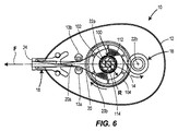
更には、摩擦部材104が巻取リール16により支持され、また同心に周囲に配置されるように説明及び図示したが、他の実施形態においては、摩擦部材104を操出リール14により支持し、また同心に周囲に配置し得る。例えば、図6に図示のように、摩擦部材104が、操出リール14の駆動リム109の駆動面109aにより支持され、また同心に周囲に配置されたOリングを含み得る。このように構成されるならば、付与力Fの増加に応じて摩擦部材104が巻取リール16から離れるように変位して付勢部材102を圧縮することを除いて、可変式クラッチ機構が上述したものと同様に概して機能する。従って、本開示の摩擦部材104は、操出リール14又は巻取リール16により支持され、また同心に周囲に配置可能であるものと理解されるべきである。
Further, while the
更には、摩擦部材104がシリコーン又は弾性材料を含むように説明したが、他の実施形態においては、摩擦部材104が、供給及び巻取リール14、16の間に摩擦を生じさせることが可能な任意の他の種類の材料を含むことができる。例えば、摩擦部材104が、クラッチ板、フラットゴムワッシャー、粘性液体、又は本明細書に説明の態様で可変な摩擦を生成可能である材料及び/又は構成部品の通例の任意の他の構成を含み得る。
Further, although the
本開示は、可変式クラッチ機構の様々な実施形態を明示的に説明したが、本発明は、本明細書に記載されるいずれの特徴によっても限定されることは意図されない。むしろ、本発明は、以下の請求の範囲の趣旨および範囲によって定義されるべきであり、すべてのその均等物を含む。 Although this disclosure has explicitly described various embodiments of a variable clutch mechanism, the present invention is not intended to be limited by any of the features described herein. Rather, the invention is to be defined by the spirit and scope of the following claims, including all equivalents thereof.
Claims (12)
第2シャフトに回転可能に設けられた第2リール;
前記第1リール及び前記第1シャフトの間に設けられた付勢部材であって、前記第1リールが第1位置及び少なくとも第2位置の間で前記第1シャフトに対して半径方向に可動であり、当該付勢部材が前記第1リールを前記第1位置へ付勢する;及び
摩擦部材の少なくとも一部が、前記第1リール及び前記第2リールの間に設けられ、また前記第1リールが前記第1位置にある時に第1垂直力を生じさせ、前記第1リールが前記第2位置にある時に第2垂直力を生じさせるように配置される、摩擦部材;
を備え、
前記付勢部材が、前記第1シャフトに回転可能に設けられたハブ及び前記ハブから半径方向に離れるように延在する複数の可撓性指部を備え、前記可撓性指部が、前記ハブに接続した近端部及び前記ハブから離間した遠端部を有し、1以上の前記遠端部が、前記第1リールに接触し、
前記第1垂直力が前記第2垂直力よりも大きく、
前記第1リールが、搬送リボンと、アプリケータヘッドにより基材に対して貼られるように適合したマーキングテープを含むテープの供給源を支持するように適合した繰出リールを含み、また前記第2リールが、前記マーキングテープが前記基材に転写された後に前記搬送リボンを回収するための巻取リールを含む、クラッチ機構。 A first reel rotatably mounted on the first shaft;
A second reel rotatably mounted on the second shaft;
An urging member provided between the first reel and the first shaft, wherein the first reel is movable in a radial direction with respect to the first shaft between a first position and at least a second position. And the biasing member biases the first reel to the first position; and at least a portion of the friction member is provided between the first reel and the second reel, and the first reel A friction member arranged to generate a first normal force when the is in the first position and to generate a second normal force when the first reel is in the second position;
With
The biasing member includes a hub rotatably provided on the first shaft and a plurality of flexible fingers extending radially away from the hub, wherein the flexible fingers are A near end connected to the hub and a far end spaced from the hub, wherein one or more of the far ends are in contact with the first reel;
The first normal force is greater than the second normal force;
The first reel includes a delivery reel adapted to support a source of tape including a transport ribbon and a marking tape adapted to be applied to a substrate by an applicator head; and the second reel The clutch mechanism includes a take-up reel for collecting the transport ribbon after the marking tape is transferred to the substrate .
前記筐体により支持されるアプリケータヘッド;及び
請求項1に記載のクラッチ機構、
を備えるテープディスペンサ。 Housing;
An applicator head supported by the housing; and a clutch mechanism according to claim 1,
A tape dispenser comprising:
Applications Claiming Priority (3)
| Application Number | Priority Date | Filing Date | Title |
|---|---|---|---|
| US12/981,324 US8578999B2 (en) | 2010-12-29 | 2010-12-29 | Variable clutch mechanism and correction tape dispenser with variable clutch mechanism |
| US12/981,324 | 2010-12-29 | ||
| PCT/US2011/052246 WO2012091767A1 (en) | 2010-12-29 | 2011-09-20 | Variable clutch mechanism and correction tape dispenser with variable clutch mechanism |
Publications (3)
| Publication Number | Publication Date |
|---|---|
| JP2014508083A JP2014508083A (en) | 2014-04-03 |
| JP2014508083A5 JP2014508083A5 (en) | 2014-05-15 |
| JP5755755B2 true JP5755755B2 (en) | 2015-07-29 |
Family
ID=44675882
Family Applications (1)
| Application Number | Title | Priority Date | Filing Date |
|---|---|---|---|
| JP2013547460A Expired - Fee Related JP5755755B2 (en) | 2010-12-29 | 2011-09-20 | Variable clutch mechanism and correction tape dispenser having variable clutch mechanism |
Country Status (5)
| Country | Link |
|---|---|
| US (1) | US8578999B2 (en) |
| JP (1) | JP5755755B2 (en) |
| CN (1) | CN103339048B (en) |
| FR (1) | FR2969991B1 (en) |
| WO (1) | WO2012091767A1 (en) |
Families Citing this family (8)
| Publication number | Priority date | Publication date | Assignee | Title |
|---|---|---|---|---|
| WO2013063606A1 (en) * | 2011-10-28 | 2013-05-02 | Berk Jed | Interactive entertainment device for lighter-than-air balloons |
| FR3008645B1 (en) * | 2013-07-22 | 2016-01-08 | Bic Soc | MANUAL APPLICATOR |
| US10478357B2 (en) * | 2015-08-05 | 2019-11-19 | Rowan University | Bandage and medical fabrics dispensers |
| JP1574143S (en) * | 2016-07-01 | 2017-04-17 | ||
| JP6916508B2 (en) * | 2016-11-15 | 2021-08-11 | プラス株式会社 | Coating film transfer tool |
| FR3071239B1 (en) | 2017-09-20 | 2021-03-05 | SOCIéTé BIC | MANUAL APPLICATION DEVICE BY TAPE OF A COATING ON A SUBSTRATE |
| USD880586S1 (en) * | 2017-12-21 | 2020-04-07 | Tombow Pencil Co., Ltd. | Correction tape dispenser |
| US11866284B2 (en) * | 2020-12-21 | 2024-01-09 | Todd Sternberg | Automatic tape dispensing system |
Family Cites Families (328)
| Publication number | Priority date | Publication date | Assignee | Title |
|---|---|---|---|---|
| US198777A (en) | 1878-01-01 | Improvement in file-handles | ||
| US2907190A (en) | 1957-06-27 | 1959-10-06 | Revere Camera Co | Friction clutch |
| US3443375A (en) | 1967-08-11 | 1969-05-13 | Gen Time Corp | Friction mechanism for clock |
| EP0064358A1 (en) | 1981-04-30 | 1982-11-10 | Honeywell Inc. | Clutch assembly |
| FR2559221B3 (en) | 1984-02-06 | 1986-01-24 | Catep | DEVICE FOR DRIVING A ROTARY SHAFT BY MEANS OF AN INTERNAL COMBUSTION ENGINE, FOR EXAMPLE FOR A LIGHT OR ULTRA-LIGHT FLYING MACHINE |
| JPS6157370A (en) | 1984-07-31 | 1986-03-24 | Shigeru Tamai | Correcting implement for character or the like |
| DE3436523A1 (en) | 1984-10-05 | 1986-04-10 | Heinrich Hermann Gmbh + Co, 7000 Stuttgart | HAND DISPENSING DEVICE FOR DONATING AND PRESSING ADHESIVE LABELS |
| US4750878A (en) | 1985-08-09 | 1988-06-14 | Automotive Products Plc | Retainer bushing |
| JPS6384998A (en) * | 1986-09-30 | 1988-04-15 | 三菱鉛筆株式会社 | Sticking tool for erroneous writing correction tape |
| JPH0321997Y2 (en) | 1986-09-30 | 1991-05-14 | ||
| US4718971A (en) | 1986-10-09 | 1988-01-12 | Moore Push-Pin Company | Dispenser for a transfer adhesive |
| DE3638722A1 (en) | 1986-11-13 | 1988-05-26 | Pelikan Ag | DEVICE FOR APPLYING AN ADHESIVE FILM |
| CH668763A5 (en) | 1986-11-18 | 1989-01-31 | Capitol Trading Sa | PORTABLE APPARATUS FOR ADHESIVE TRANSFER APPLICATION. |
| US4851074A (en) | 1987-05-27 | 1989-07-25 | Uchida Hiromichi | Automatic transferring device for double-coated adhesive tape |
| DE3718065C1 (en) | 1987-05-28 | 1988-08-11 | Doro Tape Ehlis Kg | Handheld device for applying a double-sided adhesive tape together with a cover strip |
| DE3736367C1 (en) | 1987-10-27 | 1989-02-23 | Pelikan Ag | Handheld device for transferring a film from a carrier film to a substrate |
| DE3736357C2 (en) | 1987-10-27 | 1995-11-09 | Pelikan Ag | Handheld device for transferring a film from a carrier film to a substrate |
| US5135798A (en) | 1987-12-03 | 1992-08-04 | Pelikan Aktiengesellschaft | Multilayer, flexible transfer strip |
| US4891260A (en) | 1987-12-03 | 1990-01-02 | Pelikan Aktiengesellschaft | Multilayer flexible transfer ribbon |
| DE3832163C1 (en) | 1988-09-22 | 1989-11-23 | Pelikan Ag, 3000 Hannover, De | |
| US4891090A (en) | 1988-10-04 | 1990-01-02 | Moore Push-Pin Company | Two-reel dispenser for a transfer adhesive |
| DE3834097C1 (en) | 1988-10-07 | 1990-03-29 | Pelikan Ag, 3000 Hannover, De | Device for transferring an adhesive film from a carrier tape onto a substrate |
| DE8813861U1 (en) | 1988-11-05 | 1988-12-22 | Pelikan Ag, 3000 Hannover, De | |
| DE3837621C1 (en) | 1988-11-05 | 1990-04-05 | Pelikan Ag, 3000 Hannover, De | |
| DE3842350A1 (en) | 1988-12-16 | 1990-06-21 | Pelikan Ag | Deflection element for guiding a backing tape which is coated with adhesive on one side |
| DE3900156A1 (en) | 1989-01-04 | 1990-07-05 | Czewo Plast Kunststofftech | DEVICE FOR APPLYING AN ADHESIVE FILM |
| DE3902553C2 (en) | 1989-01-28 | 1993-12-23 | Henkel Kgaa | Handheld device for transferring a film from a carrier film to a substrate |
| DE3907753C1 (en) | 1989-03-10 | 1990-09-06 | Pelikan Ag, 3000 Hannover, De | |
| DE3911402A1 (en) | 1989-04-07 | 1990-10-11 | Wischerath Josef Gmbh Co Kg | Device for applying an adhesive material |
| AU628179B2 (en) * | 1989-05-20 | 1992-09-10 | Fujikagakushi Kogyo Kabushiki Kaisha | Transcriber of transfer film |
| DE3925130A1 (en) | 1989-07-28 | 1991-01-31 | Pelikan Ag | MULTILAYER, FLEXIBLE MARKING BAND |
| ATE93812T1 (en) | 1989-12-27 | 1993-09-15 | Czewoplast Kunststofftechnik G | DISPENSER FOR APPLYING AN ADHESIVE MATERIAL TO A SUBPAPER. |
| DE4034145A1 (en) | 1990-04-30 | 1991-10-31 | Tipp Ex Gmbh & Co Kg | Hand device for moving film from carrier strip - has winding and storage spool cores connected by endless belt |
| EP0479221B1 (en) | 1990-10-05 | 1996-07-31 | Fuji Kagakushi Kogyo Co., Ltd. | Transfer tape for masking correction |
| DE4039683A1 (en) | 1990-12-12 | 1992-06-17 | Tipp Ex Gmbh & Co Kg | Hand-held dispenser transferring film of material - uses carrier tape drawn from spool by passing probe across surface of substrate to be covered by adhesive, covering or coloured material |
| DE4104331A1 (en) | 1991-02-13 | 1992-08-27 | Henkel Kgaa | Dispenser for adhesive tape - separates backing strip from tape and has second roller to receive backing strip |
| DE4120031C1 (en) | 1991-06-18 | 1992-10-22 | Pelikan Ag, 3000 Hannover, De | Glue transferring device - has frame with band reel and divider which is varied as function of reel diameter so distance of cutting of reel from outside of band car be varied |
| JP2544030Y2 (en) | 1991-07-31 | 1997-08-13 | シードゴム工業株式会社 | Paint transfer tool |
| JP2639606B2 (en) | 1991-08-30 | 1997-08-13 | シードゴム工業株式会社 | Paint transfer tool |
| US5316613A (en) | 1991-09-06 | 1994-05-31 | Minnesota Mining And Manufacturing Company | Definite length transfer adhesive dispenser |
| EP0606477A4 (en) | 1991-10-02 | 1994-11-09 | Fuji Kagaku Shikogyo | Instrument for transferring coating film. |
| DE4139808C1 (en) | 1991-12-03 | 1993-02-04 | Pelikan Ag, 3000 Hannover, De | |
| US5281298A (en) | 1992-03-03 | 1994-01-25 | The Gillette Company | Film transfer device |
| DE4217295A1 (en) | 1992-05-25 | 1993-12-02 | Tipp Ex Gmbh & Co Kg | Manual applicator transferring adhesive film from support strip to substrate - has slip clutch as annular clamp or spring between rotary and bearing portions |
| DE4217294A1 (en) | 1992-05-25 | 1993-12-02 | Tipp Ex Gmbh & Co Kg | Manual applicator transferring cover film from support strip to substrate - has support strip pulled from stock reel, guided round rotary roller mounted in housing |
| DE4220712C3 (en) | 1992-06-24 | 2002-01-24 | Tipp Ex Gmbh & Co Kg | Handheld device for transferring a film from a carrier tape to a substrate |
| DE4220843C1 (en) | 1992-06-25 | 1993-08-05 | Citius Buerotechnik Gmbh, 8906 Gersthofen, De | |
| JPH06127774A (en) * | 1992-10-14 | 1994-05-10 | Fujicopian Co Ltd | Coating film copying tool |
| US5310437A (en) | 1992-10-15 | 1994-05-10 | The Gillette Company | Single spool correction tape dispenser |
| US5310445A (en) | 1992-10-15 | 1994-05-10 | The Gillette Company | Tape dispenser |
| JP2540232Y2 (en) | 1992-12-28 | 1997-07-02 | 東洋ケミカル株式会社 | Automatic transfer unit for double-sided adhesive transfer tape |
| US5393368A (en) | 1993-02-10 | 1995-02-28 | The Gillette Company | Correction tape dispenser |
| US5499877A (en) | 1993-04-06 | 1996-03-19 | Fujicopian Co., Ltd. | Transfer ribbon cassette, a case for enclosing the cassette, and a paint film transfer device having the same |
| US5595626A (en) | 1993-04-26 | 1997-01-21 | Pentel Kabushiki Kaisha | Tape dispenser |
| US5714035A (en) | 1993-06-17 | 1998-02-03 | The Gillette Company | Correction tape dispenser |
| DE4322118C1 (en) | 1993-07-02 | 1994-11-17 | Pelikan Ag | Handheld device for transferring a film from a carrier tape to a substrate |
| DE4322120C1 (en) | 1993-07-02 | 1995-01-19 | Pelikan Ag | Exchangeable cassette for a hand-held device for transferring a film from a carrier tape to a substrate |
| DE4322117C1 (en) | 1993-07-02 | 1994-11-10 | Pelikan Ag | Manual device for transferring a film from a backing ribbon onto a base |
| JP2807805B2 (en) * | 1993-09-22 | 1998-10-08 | シードゴム工業株式会社 | Paint transfer tool |
| JP2829699B2 (en) | 1993-12-03 | 1998-11-25 | シードゴム工業株式会社 | Paint transfer tool |
| US5685944A (en) | 1994-04-28 | 1997-11-11 | Fujicopian Co., Ltd. | Film transfer apparatus and a film transfer roller used therein |
| DE9407305U1 (en) | 1994-05-02 | 1994-09-22 | Czewo Plast Kunststofftech | Device for delivering order material |
| US5507908A (en) | 1994-06-02 | 1996-04-16 | Chinon Industries, Incorporated | Coloring apparatus |
| JPH0839905A (en) | 1994-08-01 | 1996-02-13 | Fujicopian Co Ltd | Coating film transfer tool |
| GB9422905D0 (en) | 1994-11-14 | 1995-01-04 | Gillette Co | Tape dispensers |
| TW318812B (en) * | 1994-12-12 | 1997-11-01 | Yutoku Gum Kogyo Kk | |
| JP3027309B2 (en) * | 1994-12-12 | 2000-04-04 | シードゴム工業株式会社 | Tape cartridge for paint film transfer tool and paint film transfer tool |
| JP2943134B2 (en) | 1995-11-01 | 1999-08-30 | シードゴム工業株式会社 | Tape cartridge for paint film transfer tool and paint film transfer tool |
| JP3306464B2 (en) | 1994-12-26 | 2002-07-24 | ユニオンケミカー株式会社 | Transfer device |
| US5472560A (en) | 1995-02-01 | 1995-12-05 | Lin S. H. Horng | Tape dispenser |
| DE29502642U1 (en) | 1995-02-17 | 1996-06-13 | Tipp Ex Gmbh & Co Kg | Handheld device for transferring a film from a carrier tape to a substrate |
| AU692366B2 (en) | 1995-03-14 | 1998-06-04 | Pritt Produktionsgesellschaft Mbh | Multi-layer, flexible transfer strip, a process for its production and its use in a hand device |
| JP2869855B2 (en) | 1995-03-28 | 1999-03-10 | 株式会社トンボ鉛筆 | Eraser |
| JP2688184B2 (en) | 1995-04-07 | 1997-12-08 | フジコピアン株式会社 | Pressure-sensitive correction tape |
| JP3606645B2 (en) | 1995-07-24 | 2005-01-05 | フジコピアン株式会社 | Film transfer roller |
| DE19533567B4 (en) | 1995-09-11 | 2008-04-24 | SOCIéTé BIC | Hand-held device for applying a marking ink to a flat substrate |
| US6568450B1 (en) | 1995-10-02 | 2003-05-27 | Berol Corporation | Tape dispenser |
| US6112796A (en) | 1995-10-02 | 2000-09-05 | The Gillette Company | Tape dispenser |
| US6808565B1 (en) | 1995-10-06 | 2004-10-26 | Seed Rubber Co., Ltd. | Clutch mechanism of coat film transfer tool and coat film transfer tool |
| ES2225861T3 (en) | 1995-10-06 | 2005-03-16 | Seed Rubber Company Ltd. | CLUTCH MECHANISM OF A FILM TRANSFER UTENSIL FORMING A COVER LAYER AND FILM TRANSFER UTENSIL FORMING A COVER LAYER. |
| JP3516188B2 (en) | 1995-10-27 | 2004-04-05 | 株式会社トンボ鉛筆 | Transfer tape transfer and take-up part of applicator |
| US6162492A (en) | 1996-01-26 | 2000-12-19 | Citius Burotechnik Gmbh | Multi-layer correction and/or marking material, process for its production and its use |
| DE19604056C1 (en) | 1996-02-05 | 1997-07-24 | Pritt Produktionsgesellschaft | Handheld device for transferring a film from a carrier film to a substrate |
| DE19604617C2 (en) | 1996-02-08 | 2003-02-13 | Henkel Kgaa | Handheld device for transferring a film from a carrier film to a substrate |
| DE19605811C1 (en) | 1996-02-16 | 1996-10-17 | Pritt Produktionsgesellschaft | Hand tool for transferring adhesive film from carrier tape to substrate |
| DE19606626C2 (en) | 1996-02-22 | 1998-05-20 | Pritt Produktionsgesellschaft | Friction brake for a dispenser for torque-limiting power transmission between a spool core of a spool for winding or unwinding a tape and a rotary holder |
| US5759270A (en) | 1996-02-29 | 1998-06-02 | Katsuyuki Miyazaki | Correction tape adhesiver for correcting mistyped letters |
| DE19609533C1 (en) | 1996-03-11 | 1997-02-27 | Pritt Produktionsgesellschaft | Winding-spool drive mechanism for transfer tape |
| DE19617850C1 (en) | 1996-05-03 | 1997-06-05 | Henkel Kgaa | Multilayered flexible transfer strip with auxiliary support and pressure sensitive adhesive layer |
| DE19635586B4 (en) | 1996-09-02 | 2005-10-20 | Bic Clichy Soc | Handheld device for transferring a film from z. B. adhesive or opaque or colored material from a wound on a supply reel carrier tape on a substrate |
| DE19635587B4 (en) | 1996-09-02 | 2005-12-08 | SOCIéTé BIC | Handheld device for transferring a film from z. B.klebendem, opaque or colored material from a wound on a supply reel carrier tape to a substrate |
| DE19702345A1 (en) | 1997-01-23 | 1998-07-30 | Tipp Ex Gmbh & Co Kg | Handheld device for transferring a film from a carrier tape to a substrate |
| US5795085A (en) | 1997-03-05 | 1998-08-18 | Yoo; Kwang-Ho | Correction tape |
| JPH10250290A (en) * | 1997-03-18 | 1998-09-22 | Tombow Pencil Co Ltd | Feeding and winding mechanism for transfer tape of coating applicator |
| JP3879078B2 (en) | 1997-03-31 | 2007-02-07 | 株式会社トンボ鉛筆 | Applicator |
| EP0993414A1 (en) | 1997-06-30 | 2000-04-19 | Kores Holding Zug AG | Reel arrangement |
| JP3505673B2 (en) | 1997-07-23 | 2004-03-08 | 株式会社トンボ鉛筆 | Applicator |
| JP3296265B2 (en) | 1997-09-12 | 2002-06-24 | 株式会社シード | Clutch mechanism of coating film transfer device and coating film transfer device |
| NL1009050C2 (en) | 1997-10-31 | 1999-05-10 | Raytec Bv | Material transfer device. |
| JP3909378B2 (en) | 1997-11-13 | 2007-04-25 | フジコピアン株式会社 | Pressure sensitive correction tape |
| USD400585S (en) | 1998-01-21 | 1998-11-03 | The Gillette Company | Tape dispenser |
| DE29801395U1 (en) | 1998-01-30 | 1998-05-28 | Henkel Kgaa | Adhesive dispenser |
| JPH11227385A (en) | 1998-02-12 | 1999-08-24 | Fujicopian Co Ltd | Coating film transfer implement |
| JP3008025B2 (en) | 1998-03-17 | 2000-02-14 | 東洋ケミカル株式会社 | Adhesive transfer device |
| US6273162B1 (en) | 1998-04-10 | 2001-08-14 | Sumitomo Rubber Industries, Ltd. | Pneumatic tire with specified bead portion |
| DE19816925B4 (en) | 1998-04-16 | 2009-12-10 | SOCIéTé BIC | A handheld device for transferring a film from a carrier tape to a substrate |
| US5942036A (en) | 1998-05-12 | 1999-08-24 | You; Kwang-Ho | Correction tape roller device |
| DE19824551A1 (en) | 1998-06-03 | 1999-12-09 | Henkel Kgaa | Handheld device for transferring a film from a carrier tape to a substrate |
| JPH11348493A (en) | 1998-06-08 | 1999-12-21 | Seed Rubber Kogyo Kk | Tape cartridge for coating film transferer and coating film transferer |
| JP3705325B2 (en) | 1998-06-10 | 2005-10-12 | 株式会社トンボ鉛筆 | Pressure sensitive transfer correction tape |
| US6125903A (en) | 1998-06-15 | 2000-10-03 | Toyo Chemical Co., Ltd. | Adhesive transfer device |
| TW394747B (en) | 1998-06-24 | 2000-06-21 | Plus Kk | A Coated film transfer-printing apparatus |
| US6065887A (en) | 1998-06-25 | 2000-05-23 | You; Kwang Ho | Correction tape with a cap holder |
| JP2000025392A (en) | 1998-07-08 | 2000-01-25 | Seed Rubber Kogyo Kk | Tape cartridge for coating film transfer implement and coating film transfer implement |
| US6335546B1 (en) | 1998-07-31 | 2002-01-01 | Sharp Kabushiki Kaisha | Nitride semiconductor structure, method for producing a nitride semiconductor structure, and light emitting device |
| DE59905667D1 (en) | 1998-08-19 | 2003-06-26 | Pritt Produktionsgesellschaft | DEVICE FOR TRANSFERRING A SUBSTANCE IN THE FORM OF A FILM APPLIED ON A CARRIER TAPE |
| TR200100127T2 (en) | 1998-08-19 | 2001-06-21 | Pritt Produktionsgesellschaft Mbh | Instrument for transferring the film-shaped material placed on a carrier tape to a substrate |
| JP2995659B1 (en) | 1998-09-18 | 1999-12-27 | 株式会社トンボ鉛筆 | Paint transfer tool |
| JP3503052B2 (en) | 1998-09-25 | 2004-03-02 | 株式会社トンボ鉛筆 | Transfer head in coating film transfer tool |
| DE69909942T2 (en) | 1998-11-19 | 2004-04-01 | Fujicopian Co., Ltd. | Pressure sensitive transfer ribbon |
| US6352770B1 (en) | 1999-01-15 | 2002-03-05 | Bic Corporation | Correction tape having dye migration blocking properties |
| CA2359324C (en) | 1999-01-15 | 2007-07-24 | Renate Nienaber | Correction tape having dye migration blocking properties |
| JP4281147B2 (en) | 1999-04-14 | 2009-06-17 | 株式会社トンボ鉛筆 | Applicator |
| JP3622141B2 (en) | 1999-05-28 | 2005-02-23 | 株式会社トンボ鉛筆 | Axial attachment structure in applicator |
| JP2000343890A (en) | 1999-06-07 | 2000-12-12 | Fujicopian Co Ltd | Film transfer tool |
| US6260599B1 (en) | 1999-06-11 | 2001-07-17 | Kwang-Ho You | Correction tape roller device |
| JP3618586B2 (en) | 1999-06-25 | 2005-02-09 | 株式会社壽 | Film transfer tool |
| JP2001071689A (en) | 1999-07-06 | 2001-03-21 | Seed Rubber Kogyo Kk | Tape cartridge for tarnsferring coating film and coating film transfer tool |
| JP2001018587A (en) | 1999-07-06 | 2001-01-23 | Seed Rubber Kogyo Kk | Coating film transfer head device and coating film transfer tool |
| JP4408486B2 (en) | 1999-07-27 | 2010-02-03 | プラスステーショナリー株式会社 | Power transmission device for feeding core and winding core in coating film transfer tool |
| DE19936445B4 (en) | 1999-08-03 | 2004-03-04 | SOCIéTé BIC | Handheld device for transferring a film from a carrier tape to a substrate |
| US6331352B1 (en) | 1999-08-13 | 2001-12-18 | Bic Corporation | Correction tape having dye migration blocking properties |
| US6499524B1 (en) | 1999-09-07 | 2002-12-31 | Berol Corporation | Dispenser for applying a material to a surface |
| US6321815B1 (en) | 1999-09-24 | 2001-11-27 | Kwang-Ho You | Protector for leading end of correction tape |
| DE29918667U1 (en) | 1999-10-22 | 1999-12-30 | Bic Deutschland Gmbh & Co | Handheld device for transferring a film from a carrier tape to a substrate, with a backstop |
| JP2001138690A (en) | 1999-11-15 | 2001-05-22 | Tombow Pencil Co Ltd | Coating tool |
| DE60009252T2 (en) | 2000-01-06 | 2005-01-27 | Tombow Pencil Co., Ltd. | Job head for an application device |
| DE10001465C2 (en) | 2000-01-15 | 2003-11-13 | Pritt Produktionsgesellschaft | Device for transferring a substance applied in the form of a film onto a carrier tape onto a substrate |
| ATE276957T1 (en) | 2000-02-25 | 2004-10-15 | Bic Soc | HAND-HELD DEVICE WITH A MOVABLE APPLICATION ELEMENT FOR TRANSFERRING A FILM FROM A CARRIER STRIP TO A SUBSTRATE |
| WO2001062645A1 (en) | 2000-02-25 | 2001-08-30 | Bic Deutschland Gmbh & Co. | A hand-held device for transferring a film onto a substrate, comprising a concealable application member |
| CA2400275A1 (en) | 2000-02-25 | 2001-08-30 | Bic Deutschland Gmbh & Co. | Dispenser with conveyor coil |
| CN1216780C (en) | 2000-02-25 | 2005-08-31 | Bic学会 | A hand-held device for transferring a film from a backing tape onto a substrate having backing tape reels arranged next to each other |
| ES2225528T3 (en) | 2000-02-25 | 2005-03-16 | Societe Bic | PORTABLE DEVICE FOR THE APPLICATION OF A WHOLE BAND IN A SUBSTRATE. |
| AU769504B2 (en) | 2000-02-25 | 2004-01-29 | Societe Bic | Hand-held device for transferring a film and having an angular application member |
| CN1178829C (en) | 2000-06-30 | 2004-12-08 | 普乐士文具株式会社 | Film delivery means and method for making minor diameter roll of delivery head thereof |
| US6454856B1 (en) | 2000-07-17 | 2002-09-24 | Gye Ho Jung | Structure of winding correction tape in correction tape adhesive |
| JP4491573B2 (en) | 2000-07-19 | 2010-06-30 | フジコピアン株式会社 | Ink ribbon cassette |
| JP4423439B2 (en) | 2000-08-30 | 2010-03-03 | フジコピアン株式会社 | Film transfer tool |
| DE60012924T2 (en) | 2000-09-08 | 2005-01-13 | SOCIéTé BIC | Slip clutch for torque-limiting power transmission, in particular for a hand-held device for transmitting a film from a carrier tape to a substrate |
| AT410936B (en) | 2000-10-09 | 2003-08-25 | Kores Holding Zug Ag | COIL ARRANGEMENT |
| EP1201588B1 (en) | 2000-10-30 | 2004-10-27 | Société BIC | Hand-held device for applying a film of for example adhesive or covering or coloured material onto a substrate |
| US6453969B1 (en) | 2000-11-28 | 2002-09-24 | Bic Corporation | Viscous clutch for a correction tape reel assembly |
| DE10100932B4 (en) | 2001-01-10 | 2005-06-23 | Pritt Produktionsgesellschaft Mbh | Apparatus for transferring a substance applied in the form of a film to a carrier tape onto a substrate |
| JP2002234517A (en) | 2001-02-07 | 2002-08-20 | Seed:Kk | Mark transferring device and mark transferring tape |
| US7093641B2 (en) | 2001-03-05 | 2006-08-22 | Henkel Corporation | Robotic tape applicator and method |
| JP4620270B2 (en) | 2001-03-14 | 2011-01-26 | 株式会社シード | Mark transfer tool and mark transfer tape |
| JP2002337830A (en) | 2001-05-18 | 2002-11-27 | Seed:Kk | Mark transferring device and mark transferring tape |
| JP4538647B2 (en) * | 2001-03-28 | 2010-09-08 | フジコピアン株式会社 | Film transfer tool |
| ES2353056T3 (en) | 2001-04-09 | 2011-02-25 | SOCIéTé BIC | HAND DEVICE TO TRANSMIT A FILM TO A SUBSTRATE AND CONTAINING AN APPLICATOR THAT INCLUDES A PLURALITY OF APPLICATION EDGES. |
| DE20121351U1 (en) | 2001-04-17 | 2002-07-18 | Henkel Kgaa | handset |
| AU2002258848A1 (en) | 2001-04-18 | 2002-11-05 | Bal Seal Engineering | Self contained anti-blowout seal for fluids or gases |
| JP2002348029A (en) | 2001-05-21 | 2002-12-04 | Seed:Kk | Mark transfer tool, and mark transfer tape |
| JP2002337831A (en) | 2001-05-21 | 2002-11-27 | Seed:Kk | Mark transferring device and mark transferring tape |
| US6461068B1 (en) | 2001-06-07 | 2002-10-08 | Robert Holmes | Correction tape equipped writing instruments |
| JP4677626B2 (en) | 2001-06-21 | 2011-04-27 | フジコピアン株式会社 | Film transfer tool |
| DE60136696D1 (en) | 2001-07-05 | 2009-01-08 | Bic Soc | Hand-held device for applying an adhesive, coating or color film from a substrate to a substrate |
| JP4572045B2 (en) | 2001-08-20 | 2010-10-27 | 株式会社トンボ鉛筆 | Film transfer tool |
| JP4615781B2 (en) | 2001-08-20 | 2011-01-19 | 株式会社トンボ鉛筆 | Film transfer tool |
| WO2003022600A1 (en) | 2001-09-07 | 2003-03-20 | General Co., Ltd. | Transfer device |
| JP4690607B2 (en) | 2001-09-11 | 2011-06-01 | プラス株式会社 | Coating film transfer tool and coating film transfer tape replacement method |
| ES2305020T3 (en) | 2001-09-19 | 2008-11-01 | Societe Bic | MANUAL DEVICE FOR APPLYING A FILM OF ADHESIVE, RECURRING OR COLORING MATERIAL ON A SUBSTRATE. |
| US6622768B2 (en) | 2001-09-27 | 2003-09-23 | Kwang Ho You | Correction tape roll device |
| JP4603738B2 (en) * | 2001-09-28 | 2010-12-22 | プラス株式会社 | Coating film transfer tool |
| US6675856B2 (en) | 2001-10-23 | 2004-01-13 | Fujicopian Co., Ltd. | Coating film transfer tool |
| US6852409B2 (en) | 2002-02-08 | 2005-02-08 | Bic Corporation | Radiation-cured correction tape |
| US7093642B2 (en) | 2002-03-05 | 2006-08-22 | Henkel Corporation | Systems and methods for a robotic tape applicator |
| DE10214604B4 (en) | 2002-04-03 | 2005-10-06 | Henkel Kgaa | Apparatus for transferring a substance applied in the form of a film to a carrier tape onto a substrate |
| US6582514B1 (en) | 2002-04-23 | 2003-06-24 | Jacky Yang | Correction tape |
| JP3909681B2 (en) | 2002-05-02 | 2007-04-25 | 株式会社トンボ鉛筆 | Film transfer tool |
| JP2004074470A (en) | 2002-08-12 | 2004-03-11 | Fujicopian Co Ltd | Writing utensil integrated coating film transfer tool |
| DE60209076T2 (en) | 2002-11-22 | 2006-07-20 | SOCIéTé BIC | Friction clutch for energy transfer with limited torque between two rollers of a hanger |
| JP4461675B2 (en) | 2002-12-11 | 2010-05-12 | 株式会社シード | Transfer head structure of transfer tool and transfer tool |
| JP3747285B2 (en) | 2003-03-07 | 2006-02-22 | 光浩 柳 | Adhesive tape transfer tool |
| JP2004299249A (en) | 2003-03-31 | 2004-10-28 | Tombow Pencil Co Ltd | Coating film-transferring tool |
| DE10342085B3 (en) | 2003-09-10 | 2005-05-04 | Henkel Kgaa | tape dispenser |
| US7228882B2 (en) | 2003-09-15 | 2007-06-12 | Sanford, L.P. | Tape dispenser with a cushioned applicator tip |
| US6997229B2 (en) | 2003-09-16 | 2006-02-14 | Sanford, L.P. | Rotatable applicator tip for a corrective tape dispenser |
| EP1522514B1 (en) | 2003-10-07 | 2007-03-21 | Fujicopian Co., Ltd. | Coating film transfer tool |
| JP4505784B2 (en) | 2003-10-16 | 2010-07-21 | 株式会社シード | Transfer tool and transfer film removal material |
| JP2005174520A (en) | 2003-12-15 | 2005-06-30 | Matsushita Electric Ind Co Ltd | Memory circuit and its forming method |
| JP4517102B2 (en) | 2003-12-19 | 2010-08-04 | フジコピアン株式会社 | Writing instrument integrated film transfer tool |
| JP4411970B2 (en) | 2003-12-26 | 2010-02-10 | コクヨ株式会社 | Transfer tool |
| JP4228915B2 (en) | 2003-12-26 | 2009-02-25 | コクヨ株式会社 | Slide member locking structure and transfer tool |
| JP4186023B2 (en) | 2003-12-26 | 2008-11-26 | コクヨ株式会社 | Transfer tool |
| US7163040B2 (en) | 2004-01-13 | 2007-01-16 | Sanford L.P. | Correction tape applicator tip with cylindrical projection |
| JP2005199631A (en) | 2004-01-19 | 2005-07-28 | Kokuyo Co Ltd | Transfer implement |
| JP4460335B2 (en) | 2004-03-16 | 2010-05-12 | 株式会社トンボ鉛筆 | pancake |
| JP4389012B2 (en) | 2004-03-26 | 2009-12-24 | フジコピアン株式会社 | Film transfer tool transfer head |
| JP4478807B2 (en) | 2004-04-05 | 2010-06-09 | フジコピアン株式会社 | Film transfer tool transfer head |
| JP4274040B2 (en) | 2004-05-06 | 2009-06-03 | コクヨ株式会社 | Transfer tool |
| JP4352984B2 (en) | 2004-05-06 | 2009-10-28 | コクヨ株式会社 | Transfer tool |
| DE102004026720A1 (en) | 2004-05-28 | 2005-12-22 | Henkel Kgaa | Job foot, apparatus and refill unit for transferring a film to a substrate |
| JP2006015621A (en) | 2004-07-02 | 2006-01-19 | Fujicopian Co Ltd | Structure of end part of coating film tape |
| WO2006020918A2 (en) | 2004-08-13 | 2006-02-23 | Henkel Corporation | Systems and methods for a robotic tape applicator |
| JP4471280B2 (en) | 2004-08-31 | 2010-06-02 | 株式会社トンボ鉛筆 | Discoloring pressure-sensitive transfer correction tape and transfer tool |
| JP4418932B2 (en) | 2004-09-02 | 2010-02-24 | フジコピアン株式会社 | Film transfer tool |
| JP4431882B2 (en) | 2004-09-02 | 2010-03-17 | フジコピアン株式会社 | Film transfer tool |
| USD536091S1 (en) | 2004-10-01 | 2007-01-30 | Map Medizin-Technologies Gmbh | Mask |
| JP4568796B2 (en) | 2004-11-01 | 2010-10-27 | フジコピアン株式会社 | Film transfer tool |
| EP1817250A1 (en) | 2004-11-18 | 2007-08-15 | Ray Technology Group B.V. | Coating transfer device |
| JP4505580B2 (en) | 2004-12-17 | 2010-07-21 | フジコピアン株式会社 | Adhesive layer transfer tape transfer tool |
| JP4441667B2 (en) | 2004-12-27 | 2010-03-31 | フジコピアン株式会社 | Tape cartridge for dust removal |
| JP4491550B2 (en) | 2004-12-28 | 2010-06-30 | コクヨ株式会社 | Engaging device and transfer tool |
| JP5234556B2 (en) | 2005-01-25 | 2013-07-10 | コクヨ株式会社 | Pressure sensitive adhesive tape and transfer tool |
| JP4679165B2 (en) | 2005-01-25 | 2011-04-27 | コクヨS&T株式会社 | Adhesive products and transfer tools |
| JP4488916B2 (en) | 2005-01-26 | 2010-06-23 | 王子特殊紙株式会社 | Double-sided release film for correction tape |
| JP4617430B2 (en) | 2005-03-04 | 2011-01-26 | フジコピアン株式会社 | Film transfer tool |
| JP4644840B2 (en) | 2005-04-27 | 2011-03-09 | コクヨ株式会社 | Cover locking structure and transfer tool |
| DE102005024564B4 (en) | 2005-05-28 | 2007-04-19 | Henkel Kgaa | tape dispenser |
| USD543239S1 (en) | 2005-06-03 | 2007-05-22 | Tombow Pencil Co. Ltd. | Coating tape dispenser |
| USD542845S1 (en) | 2005-06-03 | 2007-05-15 | Tombow Pencil Co. Ltd. | Coating tape dispenser |
| AU307774S (en) | 2005-06-16 | 2006-07-10 | Tombow Pencil | Coating transfer device |
| USD543238S1 (en) | 2005-06-16 | 2007-05-22 | Tombow Pencil Co. Ltd. | Cartridge-type coating tape dispenser |
| JP4505582B2 (en) | 2005-06-20 | 2010-07-21 | フジコピアン株式会社 | Pressure sensitive adhesive tape for punching |
| ES2303154T3 (en) | 2005-06-20 | 2008-08-01 | Societe Bic | FRICTION COUPLING WITH TORICA GASKET. |
| JP4505583B2 (en) | 2005-06-20 | 2010-07-21 | フジコピアン株式会社 | Substrate-less double-sided adhesive tape used for die-cutting |
| CA114146S (en) | 2005-07-13 | 2007-11-15 | Henkel Kgaa | Correction and glue tape dispenser |
| USD542351S1 (en) | 2005-07-25 | 2007-05-08 | Societe Bic | Correction-tape dispenser |
| USD543240S1 (en) | 2005-07-28 | 2007-05-22 | Tombow Pencil Co., Ltd. | Cartridge-type coating tape dispenser |
| JP2007069529A (en) | 2005-09-08 | 2007-03-22 | Tombow Pencil Co Ltd | Film coating transfer utensil for bonding |
| USD541863S1 (en) | 2005-09-19 | 2007-05-01 | Sanford, L.P. | Correction tape dispenser |
| USD549322S1 (en) | 2005-09-26 | 2007-08-21 | Resmed Limited | Mask frame |
| USD571403S1 (en) | 2005-10-19 | 2008-06-17 | Societe Bic | Correction tape dispenser |
| JP4895578B2 (en) | 2005-11-16 | 2012-03-14 | 株式会社Adeka | Nematic liquid crystal composition |
| USD543242S1 (en) | 2005-11-21 | 2007-05-22 | Henkel Kommanditgesellschaft Auf Aktien | Correction roller |
| JP2007182534A (en) | 2005-12-08 | 2007-07-19 | Tombow Pencil Co Ltd | Pressure-sensitive transfer adhesive tape and coating film transfer tool |
| JP2007161802A (en) | 2005-12-12 | 2007-06-28 | Tombow Pencil Co Ltd | Pressure-sensitive adhesive tape, microcapsule-containing composition used for the same, and coating film-transfer tool |
| JP2007168146A (en) | 2005-12-20 | 2007-07-05 | Tombow Pencil Co Ltd | Pressure-sensitive transfer correction tape pancake |
| JP2007175886A (en) | 2005-12-27 | 2007-07-12 | Tombow Pencil Co Ltd | Pressure-sensitive transfer correction tape |
| EP1806309A1 (en) | 2006-01-04 | 2007-07-11 | Société BIC | Tape dispenser with protector |
| EP1806308A1 (en) | 2006-01-04 | 2007-07-11 | Société BIC | Tape dispenser with cover |
| USD570917S1 (en) | 2006-01-05 | 2008-06-10 | Henkel Corporation | Adhesive tape dispenser |
| EP1808395B1 (en) | 2006-01-12 | 2008-07-16 | Société BIC | Correction system with rubber elastic tension element for a gear mechanism correction tape |
| JP2007196541A (en) | 2006-01-27 | 2007-08-09 | Tombow Pencil Co Ltd | Coating film transfer implement |
| JP4769964B2 (en) | 2006-02-06 | 2011-09-07 | フジコピアン株式会社 | Film transfer tool |
| USD607055S1 (en) | 2006-02-17 | 2009-12-29 | Kores Holding Zug Ag | Correction roller |
| JP2007301835A (en) | 2006-05-11 | 2007-11-22 | Tombow Pencil Co Ltd | Coating film transfer implement |
| JP2007326960A (en) | 2006-06-08 | 2007-12-20 | Tombow Pencil Co Ltd | Pressure-sensitive transfer adhesive tape and coating film-transferring tool |
| JP5081404B2 (en) | 2006-06-23 | 2012-11-28 | フジコピアン株式会社 | Coating film transfer device |
| DE102006031173B4 (en) | 2006-07-06 | 2011-04-14 | Henkel Ag & Co. Kgaa | Apparatus for transferring a film from a carrier tape to a substrate |
| JP2008023871A (en) | 2006-07-21 | 2008-02-07 | Tombow Pencil Co Ltd | Coating film transferer and cartridge therefor |
| JP4887515B2 (en) | 2006-09-27 | 2012-02-29 | コクヨ株式会社 | Transfer tool |
| USD562404S1 (en) | 2006-09-27 | 2008-02-19 | Henkel Kommanditgesellschaft Auf Aktien | Correction roller |
| JP4899091B2 (en) | 2006-09-27 | 2012-03-21 | コクヨ株式会社 | Transfer tool |
| JP4899092B2 (en) | 2006-09-27 | 2012-03-21 | コクヨ株式会社 | Transfer tool |
| JP2008087257A (en) | 2006-09-29 | 2008-04-17 | Tombow Pencil Co Ltd | Coating film transferring tool |
| JP2008087426A (en) | 2006-10-04 | 2008-04-17 | Tombow Pencil Co Ltd | Coating film transferring tool |
| JP2008093951A (en) | 2006-10-11 | 2008-04-24 | Tombow Pencil Co Ltd | Coating film transferring tool |
| USD588644S1 (en) | 2006-10-20 | 2009-03-17 | Tombow Pencil Co., Ltd. | Coating transfer device |
| JP2008105194A (en) | 2006-10-23 | 2008-05-08 | Tombow Pencil Co Ltd | Coating film transferring tool |
| JP2008156041A (en) | 2006-12-22 | 2008-07-10 | Tombow Pencil Co Ltd | Pancake for painted film transfer tool |
| JP5070567B2 (en) | 2006-12-27 | 2012-11-14 | コクヨ株式会社 | Transfer tool |
| JP5023356B2 (en) | 2006-12-27 | 2012-09-12 | コクヨ株式会社 | Transfer tool |
| JP2008162052A (en) | 2006-12-27 | 2008-07-17 | Kokuyo Co Ltd | Transferer |
| JP2008221556A (en) | 2007-03-12 | 2008-09-25 | Tombow Pencil Co Ltd | Pressure-sensitive transfer correcting tape |
| USD570918S1 (en) | 2007-03-13 | 2008-06-10 | Henkel Kgaa | Correction roller |
| JP2008221775A (en) | 2007-03-15 | 2008-09-25 | Tombow Pencil Co Ltd | Coating film transfer implement |
| DE102007015392A1 (en) | 2007-03-28 | 2008-10-02 | Henkel Ag & Co. Kgaa | Flexible power tape |
| JP4947643B2 (en) | 2007-03-28 | 2012-06-06 | フジコピアン株式会社 | Horizontal type film transfer tool |
| JP2008254879A (en) | 2007-04-04 | 2008-10-23 | Tombow Pencil Co Ltd | Container for delivering adhesive tape |
| JP4806791B2 (en) | 2007-04-17 | 2011-11-02 | コクヨ株式会社 | Transfer tool |
| JP4752077B2 (en) | 2007-04-17 | 2011-08-17 | コクヨ株式会社 | Transfer tool |
| JP4951780B2 (en) | 2007-04-17 | 2012-06-13 | コクヨ株式会社 | Transfer tool |
| AU317501S (en) | 2007-04-19 | 2008-01-08 | Tombow Pencil | Coating film transfer apparatus |
| AU317502S (en) | 2007-04-19 | 2008-01-08 | Tombow Pencil | Coating film transfer apparatus |
| AU317701S (en) | 2007-04-19 | 2008-01-22 | Tombow Pencil | Coating film transfer apparatus |
| AU317503S (en) | 2007-04-19 | 2008-01-08 | Tombow Pencil | Coating film transfer apparatus |
| JP2008279642A (en) | 2007-05-09 | 2008-11-20 | Tombow Pencil Co Ltd | Coating film transferer |
| JP2008279719A (en) | 2007-05-14 | 2008-11-20 | Tombow Pencil Co Ltd | Coating film transferer |
| JP2010530060A (en) | 2007-05-29 | 2010-09-02 | ヘンケル コーポレイション | Adhesive detection method |
| JP4899101B2 (en) | 2007-06-07 | 2012-03-21 | コクヨ株式会社 | Transfer tool |
| JP2008307815A (en) | 2007-06-15 | 2008-12-25 | Kokuyo Co Ltd | Transfer tool |
| USD579980S1 (en) | 2007-06-19 | 2008-11-04 | Henkel Ag & Co. Kgaa | Correction roller |
| USD573195S1 (en) | 2007-06-19 | 2008-07-15 | Henkel Kgaa | Correction roller |
| USD579499S1 (en) | 2007-06-19 | 2008-10-28 | Henkel Kgaa | Correction roller |
| JP2009013199A (en) | 2007-06-29 | 2009-01-22 | Tombow Pencil Co Ltd | Tape for removing applied film and tool for removing applied film having the same |
| USD573194S1 (en) | 2007-07-10 | 2008-07-15 | Henkel Kgaa | Correction roller |
| JP4972787B2 (en) | 2007-07-27 | 2012-07-11 | コクヨ株式会社 | Transfer tool |
| JP5211339B2 (en) | 2007-07-27 | 2013-06-12 | コクヨ株式会社 | Transfer tool |
| JP4929477B2 (en) | 2007-07-27 | 2012-05-09 | コクヨ株式会社 | Transfer tool |
| USD573645S1 (en) | 2007-08-08 | 2008-07-22 | Henkel Corporation | Standing tape dispenser |
| BRPI0815702A8 (en) | 2007-08-22 | 2016-06-21 | SOCIéTé BIC | VALVE COMPRISING FIRST AND SECOND VALVE COMPONENTS |
| USD579981S1 (en) | 2007-09-25 | 2008-11-04 | Henkel Corporation | Tape dispenser |
| JP4899103B2 (en) | 2007-09-28 | 2012-03-21 | コクヨ株式会社 | Transfer device |
| JP5097991B2 (en) | 2007-12-10 | 2012-12-12 | 株式会社シード | Extraction device, collection tape and collection method for identification object |
| JP2009143065A (en) | 2007-12-12 | 2009-07-02 | Seed:Kk | Transfer implement |
| EP2070856B1 (en) | 2007-12-14 | 2013-02-13 | Société BIC | A hand-held device for applying a deposit of for example adhesive, covering or coloured material onto a correction surface |
| DE102007061859A1 (en) | 2007-12-19 | 2009-06-25 | Henkel Ag & Co. Kgaa | Process for producing a reinforced adhesive tape |
| JP5158344B2 (en) | 2007-12-26 | 2013-03-06 | フジコピアン株式会社 | Manual coating film transfer device |
| JP5158346B2 (en) | 2007-12-28 | 2013-03-06 | フジコピアン株式会社 | Coating film transfer device |
| USD580497S1 (en) | 2008-01-09 | 2008-11-11 | Henkel Corporation | Tape dispenser |
| US20090179061A1 (en) | 2008-01-11 | 2009-07-16 | Henkel Corporation | Adhesive tape dispenser and applicator |
| JP2009255330A (en) | 2008-04-14 | 2009-11-05 | Tombow Pencil Co Ltd | Coat transfer implement |
| JP2009262347A (en) | 2008-04-22 | 2009-11-12 | Tombow Pencil Co Ltd | Coating film transferring tool |
| JP2009262348A (en) | 2008-04-22 | 2009-11-12 | Tombow Pencil Co Ltd | Attachment for stationery |
| JP2009285884A (en) | 2008-05-27 | 2009-12-10 | Kokuyo Co Ltd | Transfer implement |
| JP5176140B2 (en) | 2008-05-27 | 2013-04-03 | コクヨ株式会社 | Transfer tool |
| JP5097976B2 (en) | 2008-05-30 | 2012-12-12 | フジコピアン株式会社 | Replacement cartridge and body case for coating film transfer tool |
| JP5285965B2 (en) | 2008-06-10 | 2013-09-11 | フジコピアン株式会社 | Multi-purpose film transfer tool |
| JP2010017855A (en) | 2008-07-08 | 2010-01-28 | Fujicopian Co Ltd | Coat transfer gadget |
| JP5307463B2 (en) | 2008-07-14 | 2013-10-02 | 株式会社トンボ鉛筆 | stationery |
| US20100018653A1 (en) | 2008-07-25 | 2010-01-28 | Henkel Corporation | Adhesive tape dispenser and applicator |
| DE102008036718A1 (en) | 2008-08-07 | 2010-02-18 | Henkel Ag & Co. Kgaa | Erstöffnungssicherung |
| GB2463065B (en) | 2008-09-01 | 2012-11-07 | Loctite R & D Ltd | Transferable curable non-liquid film on a release substrate |
| USD600751S1 (en) | 2008-09-12 | 2009-09-22 | Sanford, L.P. | Correction tape dispenser |
| JP2010069827A (en) | 2008-09-22 | 2010-04-02 | Tombow Pencil Co Ltd | Coating film transfer tool |
| JP2010083086A (en) | 2008-10-01 | 2010-04-15 | Tombow Pencil Co Ltd | Tape delivery apparatus |
| JP5011558B2 (en) | 2008-10-02 | 2012-08-29 | コクヨ株式会社 | Transfer tool |
| USD588646S1 (en) | 2008-10-07 | 2009-03-17 | Henkel Corporation | Tape dispenser |
| USD591354S1 (en) | 2008-10-07 | 2009-04-28 | Henkel Corporation | Tape dispenser |
| JP5307506B2 (en) | 2008-10-31 | 2013-10-02 | 株式会社トンボ鉛筆 | stationery |
| USD619655S1 (en) | 2009-02-23 | 2010-07-13 | Tombow Pencil Co., Ltd. | Correction tape dispenser |
| USD620526S1 (en) | 2009-02-23 | 2010-07-27 | Tombow Pencil Co., Ltd. | Correction tape dispenser |
| AU327673S (en) | 2009-03-13 | 2009-09-18 | Tombow Pencil | Dispenser |
| AU327672S (en) | 2009-03-13 | 2009-09-18 | Tombow Pencil | Dispenser |
| AU327671S (en) | 2009-03-13 | 2009-09-18 | Tombow Pencil | Dispenser |
| USD603903S1 (en) | 2009-04-28 | 2009-11-10 | Sanford, L.P. | Correction tape dispenser |
| JP4783851B2 (en) | 2009-12-27 | 2011-09-28 | 株式会社シード | Transfer tool |
-
2010
- 2010-12-29 US US12/981,324 patent/US8578999B2/en active Active
-
2011
- 2011-09-20 JP JP2013547460A patent/JP5755755B2/en not_active Expired - Fee Related
- 2011-09-20 WO PCT/US2011/052246 patent/WO2012091767A1/en active Application Filing
- 2011-09-20 CN CN201180065378.4A patent/CN103339048B/en not_active Expired - Fee Related
- 2011-09-29 FR FR1102950A patent/FR2969991B1/en not_active Expired - Fee Related
Also Published As
| Publication number | Publication date |
|---|---|
| FR2969991A1 (en) | 2012-07-06 |
| CN103339048B (en) | 2016-04-13 |
| US20120168090A1 (en) | 2012-07-05 |
| CN103339048A (en) | 2013-10-02 |
| JP2014508083A (en) | 2014-04-03 |
| FR2969991B1 (en) | 2016-04-08 |
| WO2012091767A1 (en) | 2012-07-05 |
| US8578999B2 (en) | 2013-11-12 |
Similar Documents
| Publication | Publication Date | Title |
|---|---|---|
| JP5755755B2 (en) | Variable clutch mechanism and correction tape dispenser having variable clutch mechanism | |
| JP5876590B2 (en) | Variable clutch mechanism and correction tape dispenser having variable clutch mechanism | |
| WO1993007009A1 (en) | Instrument for transferring coating film | |
| JP4588718B2 (en) | Correction tape applicator tip with cylindrical protrusion | |
| US20050056374A1 (en) | Tape dispenser with a cushioned applicator tip | |
| US6145770A (en) | Friction coupling for the torque-limiting transmission of force between a coil core for winding or unwinding a tape and a rotary support | |
| WO2010038604A1 (en) | Transfer tool | |
| TW201117969A (en) | Application-film transfer tool | |
| JP5873088B2 (en) | Correction tape dispenser with variable clutch mechanism | |
| JPH10236081A (en) | Coating film transfer tool | |
| JP2011056696A (en) | Coating film transfer implement and cartridge for coating film transfer implement | |
| JP6164498B2 (en) | Film transfer tool | |
| US6976652B2 (en) | Tool for transferring a film | |
| JP2009154382A (en) | Coating film transfer device | |
| JP6216991B2 (en) | Film transfer tool | |
| JP6233754B2 (en) | Film transfer tool | |
| JP2003094887A (en) | Clutch device of coating film transfer tool | |
| JPH07276757A (en) | Transfer ribbon casette | |
| JP2023068226A (en) | transfer tool | |
| MXPA06008038A (en) | Correction tape applicator tip with cylindrical projection | |
| JP2014226807A (en) | Coating film transfer tool | |
| JPH082188A (en) | Transfer tape feeding and taking-up mechanism for coating applicator | |
| JP2016150752A (en) | Adhesive seal sticking device | |
| JP2014115395A (en) | Endless belt and belt drive device |
Legal Events
| Date | Code | Title | Description |
|---|---|---|---|
| A521 | Request for written amendment filed |
Free format text: JAPANESE INTERMEDIATE CODE: A523 Effective date: 20140311 |
|
| A621 | Written request for application examination |
Free format text: JAPANESE INTERMEDIATE CODE: A621 Effective date: 20140311 |
|
| A977 | Report on retrieval |
Free format text: JAPANESE INTERMEDIATE CODE: A971007 Effective date: 20141210 |
|
| A131 | Notification of reasons for refusal |
Free format text: JAPANESE INTERMEDIATE CODE: A131 Effective date: 20150106 |
|
| A521 | Request for written amendment filed |
Free format text: JAPANESE INTERMEDIATE CODE: A523 Effective date: 20150403 |
|
| TRDD | Decision of grant or rejection written | ||
| A01 | Written decision to grant a patent or to grant a registration (utility model) |
Free format text: JAPANESE INTERMEDIATE CODE: A01 Effective date: 20150428 |
|
| A61 | First payment of annual fees (during grant procedure) |
Free format text: JAPANESE INTERMEDIATE CODE: A61 Effective date: 20150527 |
|
| R150 | Certificate of patent or registration of utility model |
Ref document number: 5755755 Country of ref document: JP Free format text: JAPANESE INTERMEDIATE CODE: R150 |
|
| R250 | Receipt of annual fees |
Free format text: JAPANESE INTERMEDIATE CODE: R250 |
|
| LAPS | Cancellation because of no payment of annual fees |