JP5713411B2 - Device and method for heating using RF energy - Google Patents
Device and method for heating using RF energy Download PDFInfo
- Publication number
- JP5713411B2 JP5713411B2 JP2012537480A JP2012537480A JP5713411B2 JP 5713411 B2 JP5713411 B2 JP 5713411B2 JP 2012537480 A JP2012537480 A JP 2012537480A JP 2012537480 A JP2012537480 A JP 2012537480A JP 5713411 B2 JP5713411 B2 JP 5713411B2
- Authority
- JP
- Japan
- Prior art keywords
- energy
- power
- frequency
- dissipation
- load
- Prior art date
- Legal status (The legal status is an assumption and is not a legal conclusion. Google has not performed a legal analysis and makes no representation as to the accuracy of the status listed.)
- Active
Links
- 238000000034 method Methods 0.000 title claims description 96
- 238000010438 heat treatment Methods 0.000 title description 96
- 238000012545 processing Methods 0.000 claims description 97
- 230000008878 coupling Effects 0.000 claims description 4
- 238000010168 coupling process Methods 0.000 claims description 4
- 238000005859 coupling reaction Methods 0.000 claims description 4
- 238000010408 sweeping Methods 0.000 claims description 4
- XLYOFNOQVPJJNP-UHFFFAOYSA-N water Substances O XLYOFNOQVPJJNP-UHFFFAOYSA-N 0.000 description 106
- 239000012071 phase Substances 0.000 description 78
- 230000008859 change Effects 0.000 description 70
- 239000000463 material Substances 0.000 description 70
- 230000005672 electromagnetic field Effects 0.000 description 65
- 230000006870 function Effects 0.000 description 65
- 238000010521 absorption reaction Methods 0.000 description 51
- 230000003595 spectral effect Effects 0.000 description 51
- 238000010257 thawing Methods 0.000 description 49
- 230000005540 biological transmission Effects 0.000 description 40
- 230000000875 corresponding effect Effects 0.000 description 24
- 238000012546 transfer Methods 0.000 description 24
- 238000009826 distribution Methods 0.000 description 22
- 235000013305 food Nutrition 0.000 description 18
- 230000007246 mechanism Effects 0.000 description 18
- 230000021715 photosynthesis, light harvesting Effects 0.000 description 18
- 238000001228 spectrum Methods 0.000 description 18
- 239000000203 mixture Substances 0.000 description 17
- 241000287828 Gallus gallus Species 0.000 description 16
- 235000013330 chicken meat Nutrition 0.000 description 16
- 238000004458 analytical method Methods 0.000 description 13
- 238000013021 overheating Methods 0.000 description 13
- 230000008569 process Effects 0.000 description 13
- 102100027282 Fanconi anemia group E protein Human genes 0.000 description 12
- 239000007788 liquid Substances 0.000 description 12
- 230000006837 decompression Effects 0.000 description 11
- 238000010586 diagram Methods 0.000 description 11
- 230000000694 effects Effects 0.000 description 11
- 239000007787 solid Substances 0.000 description 11
- 241000209094 Oryza Species 0.000 description 10
- 235000007164 Oryza sativa Nutrition 0.000 description 10
- 235000009566 rice Nutrition 0.000 description 10
- 238000004088 simulation Methods 0.000 description 9
- 230000035945 sensitivity Effects 0.000 description 8
- 238000004364 calculation method Methods 0.000 description 7
- 230000001276 controlling effect Effects 0.000 description 7
- 235000013372 meat Nutrition 0.000 description 7
- 238000012360 testing method Methods 0.000 description 7
- 241000251468 Actinopterygii Species 0.000 description 6
- 239000007789 gas Substances 0.000 description 6
- 230000003321 amplification Effects 0.000 description 5
- 235000015278 beef Nutrition 0.000 description 5
- 238000004422 calculation algorithm Methods 0.000 description 5
- 230000001419 dependent effect Effects 0.000 description 5
- 238000012886 linear function Methods 0.000 description 5
- 229910052751 metal Inorganic materials 0.000 description 5
- 239000002184 metal Substances 0.000 description 5
- 238000003199 nucleic acid amplification method Methods 0.000 description 5
- 239000002131 composite material Substances 0.000 description 4
- 239000004020 conductor Substances 0.000 description 4
- 238000010411 cooking Methods 0.000 description 4
- 230000002596 correlated effect Effects 0.000 description 4
- 238000001704 evaporation Methods 0.000 description 4
- 230000008020 evaporation Effects 0.000 description 4
- 238000002474 experimental method Methods 0.000 description 4
- 235000014347 soups Nutrition 0.000 description 4
- 238000013459 approach Methods 0.000 description 3
- 238000009835 boiling Methods 0.000 description 3
- 235000013351 cheese Nutrition 0.000 description 3
- 230000007423 decrease Effects 0.000 description 3
- 230000003247 decreasing effect Effects 0.000 description 3
- 238000005286 illumination Methods 0.000 description 3
- 238000003384 imaging method Methods 0.000 description 3
- 238000010606 normalization Methods 0.000 description 3
- 208000024891 symptom Diseases 0.000 description 3
- 238000011282 treatment Methods 0.000 description 3
- 241000238557 Decapoda Species 0.000 description 2
- 230000009286 beneficial effect Effects 0.000 description 2
- 230000002902 bimodal effect Effects 0.000 description 2
- 238000006243 chemical reaction Methods 0.000 description 2
- 238000004891 communication Methods 0.000 description 2
- 230000003750 conditioning effect Effects 0.000 description 2
- 238000001816 cooling Methods 0.000 description 2
- 230000001934 delay Effects 0.000 description 2
- 235000021186 dishes Nutrition 0.000 description 2
- 230000005684 electric field Effects 0.000 description 2
- 230000001747 exhibiting effect Effects 0.000 description 2
- 239000004615 ingredient Substances 0.000 description 2
- 239000000155 melt Substances 0.000 description 2
- 239000007769 metal material Substances 0.000 description 2
- 150000002739 metals Chemical class 0.000 description 2
- 238000002156 mixing Methods 0.000 description 2
- 238000012986 modification Methods 0.000 description 2
- 230000004048 modification Effects 0.000 description 2
- 238000012544 monitoring process Methods 0.000 description 2
- 239000013307 optical fiber Substances 0.000 description 2
- 235000014594 pastries Nutrition 0.000 description 2
- 239000000126 substance Substances 0.000 description 2
- 235000013311 vegetables Nutrition 0.000 description 2
- 238000010792 warming Methods 0.000 description 2
- 240000008415 Lactuca sativa Species 0.000 description 1
- 244000061456 Solanum tuberosum Species 0.000 description 1
- 235000002595 Solanum tuberosum Nutrition 0.000 description 1
- 239000006096 absorbing agent Substances 0.000 description 1
- 239000011358 absorbing material Substances 0.000 description 1
- 229910052782 aluminium Inorganic materials 0.000 description 1
- XAGFODPZIPBFFR-UHFFFAOYSA-N aluminium Chemical compound [Al] XAGFODPZIPBFFR-UHFFFAOYSA-N 0.000 description 1
- 230000003466 anti-cipated effect Effects 0.000 description 1
- 230000001580 bacterial effect Effects 0.000 description 1
- 230000006399 behavior Effects 0.000 description 1
- 230000008901 benefit Effects 0.000 description 1
- 230000015572 biosynthetic process Effects 0.000 description 1
- 210000000988 bone and bone Anatomy 0.000 description 1
- 235000008429 bread Nutrition 0.000 description 1
- 230000015556 catabolic process Effects 0.000 description 1
- 238000013479 data entry Methods 0.000 description 1
- 238000006731 degradation reaction Methods 0.000 description 1
- 238000001035 drying Methods 0.000 description 1
- 230000005288 electromagnetic effect Effects 0.000 description 1
- 230000005670 electromagnetic radiation Effects 0.000 description 1
- 230000005284 excitation Effects 0.000 description 1
- 235000019688 fish Nutrition 0.000 description 1
- 239000012530 fluid Substances 0.000 description 1
- 238000007710 freezing Methods 0.000 description 1
- 230000008014 freezing Effects 0.000 description 1
- 239000000446 fuel Substances 0.000 description 1
- 238000007429 general method Methods 0.000 description 1
- 235000015220 hamburgers Nutrition 0.000 description 1
- 230000017525 heat dissipation Effects 0.000 description 1
- 150000004677 hydrates Chemical class 0.000 description 1
- 238000010348 incorporation Methods 0.000 description 1
- 238000011534 incubation Methods 0.000 description 1
- 230000003993 interaction Effects 0.000 description 1
- 230000001788 irregular Effects 0.000 description 1
- 150000002632 lipids Chemical class 0.000 description 1
- 239000007791 liquid phase Substances 0.000 description 1
- 235000004213 low-fat Nutrition 0.000 description 1
- 230000014759 maintenance of location Effects 0.000 description 1
- 238000005259 measurement Methods 0.000 description 1
- 238000002844 melting Methods 0.000 description 1
- 230000008018 melting Effects 0.000 description 1
- 210000003205 muscle Anatomy 0.000 description 1
- 238000009828 non-uniform distribution Methods 0.000 description 1
- 230000003121 nonmonotonic effect Effects 0.000 description 1
- 230000003287 optical effect Effects 0.000 description 1
- 210000000056 organ Anatomy 0.000 description 1
- 235000015927 pasta Nutrition 0.000 description 1
- 230000000704 physical effect Effects 0.000 description 1
- 235000012015 potatoes Nutrition 0.000 description 1
- 230000002265 prevention Effects 0.000 description 1
- 102000004169 proteins and genes Human genes 0.000 description 1
- 108090000623 proteins and genes Proteins 0.000 description 1
- 230000005855 radiation Effects 0.000 description 1
- 238000001953 recrystallisation Methods 0.000 description 1
- 230000009467 reduction Effects 0.000 description 1
- 238000005057 refrigeration Methods 0.000 description 1
- 230000004044 response Effects 0.000 description 1
- 238000012552 review Methods 0.000 description 1
- 235000012045 salad Nutrition 0.000 description 1
- 150000003839 salts Chemical class 0.000 description 1
- 238000005070 sampling Methods 0.000 description 1
- 238000000926 separation method Methods 0.000 description 1
- 210000003491 skin Anatomy 0.000 description 1
- 239000007790 solid phase Substances 0.000 description 1
- 230000008685 targeting Effects 0.000 description 1
- 230000002277 temperature effect Effects 0.000 description 1
- 210000000689 upper leg Anatomy 0.000 description 1
- 239000011800 void material Substances 0.000 description 1
- 238000005303 weighing Methods 0.000 description 1
Images


Classifications
-
- H—ELECTRICITY
- H05—ELECTRIC TECHNIQUES NOT OTHERWISE PROVIDED FOR
- H05B—ELECTRIC HEATING; ELECTRIC LIGHT SOURCES NOT OTHERWISE PROVIDED FOR; CIRCUIT ARRANGEMENTS FOR ELECTRIC LIGHT SOURCES, IN GENERAL
- H05B6/00—Heating by electric, magnetic or electromagnetic fields
- H05B6/64—Heating using microwaves
- H05B6/70—Feed lines
- H05B6/705—Feed lines using microwave tuning
-
- H—ELECTRICITY
- H05—ELECTRIC TECHNIQUES NOT OTHERWISE PROVIDED FOR
- H05B—ELECTRIC HEATING; ELECTRIC LIGHT SOURCES NOT OTHERWISE PROVIDED FOR; CIRCUIT ARRANGEMENTS FOR ELECTRIC LIGHT SOURCES, IN GENERAL
- H05B1/00—Details of electric heating devices
- H05B1/02—Automatic switching arrangements specially adapted to apparatus ; Control of heating devices
-
- H—ELECTRICITY
- H05—ELECTRIC TECHNIQUES NOT OTHERWISE PROVIDED FOR
- H05B—ELECTRIC HEATING; ELECTRIC LIGHT SOURCES NOT OTHERWISE PROVIDED FOR; CIRCUIT ARRANGEMENTS FOR ELECTRIC LIGHT SOURCES, IN GENERAL
- H05B6/00—Heating by electric, magnetic or electromagnetic fields
-
- H—ELECTRICITY
- H05—ELECTRIC TECHNIQUES NOT OTHERWISE PROVIDED FOR
- H05B—ELECTRIC HEATING; ELECTRIC LIGHT SOURCES NOT OTHERWISE PROVIDED FOR; CIRCUIT ARRANGEMENTS FOR ELECTRIC LIGHT SOURCES, IN GENERAL
- H05B6/00—Heating by electric, magnetic or electromagnetic fields
- H05B6/64—Heating using microwaves
- H05B6/6447—Method of operation or details of the microwave heating apparatus related to the use of detectors or sensors
- H05B6/645—Method of operation or details of the microwave heating apparatus related to the use of detectors or sensors using temperature sensors
- H05B6/6455—Method of operation or details of the microwave heating apparatus related to the use of detectors or sensors using temperature sensors the sensors being infrared detectors
-
- H—ELECTRICITY
- H05—ELECTRIC TECHNIQUES NOT OTHERWISE PROVIDED FOR
- H05B—ELECTRIC HEATING; ELECTRIC LIGHT SOURCES NOT OTHERWISE PROVIDED FOR; CIRCUIT ARRANGEMENTS FOR ELECTRIC LIGHT SOURCES, IN GENERAL
- H05B6/00—Heating by electric, magnetic or electromagnetic fields
- H05B6/64—Heating using microwaves
- H05B6/66—Circuits
- H05B6/68—Circuits for monitoring or control
- H05B6/686—Circuits comprising a signal generator and power amplifier, e.g. using solid state oscillators
-
- H—ELECTRICITY
- H05—ELECTRIC TECHNIQUES NOT OTHERWISE PROVIDED FOR
- H05B—ELECTRIC HEATING; ELECTRIC LIGHT SOURCES NOT OTHERWISE PROVIDED FOR; CIRCUIT ARRANGEMENTS FOR ELECTRIC LIGHT SOURCES, IN GENERAL
- H05B6/00—Heating by electric, magnetic or electromagnetic fields
- H05B6/64—Heating using microwaves
- H05B6/66—Circuits
- H05B6/68—Circuits for monitoring or control
- H05B6/687—Circuits for monitoring or control for cooking
-
- H—ELECTRICITY
- H05—ELECTRIC TECHNIQUES NOT OTHERWISE PROVIDED FOR
- H05B—ELECTRIC HEATING; ELECTRIC LIGHT SOURCES NOT OTHERWISE PROVIDED FOR; CIRCUIT ARRANGEMENTS FOR ELECTRIC LIGHT SOURCES, IN GENERAL
- H05B6/00—Heating by electric, magnetic or electromagnetic fields
- H05B6/64—Heating using microwaves
- H05B6/66—Circuits
- H05B6/68—Circuits for monitoring or control
- H05B6/688—Circuits for monitoring or control for thawing
-
- H—ELECTRICITY
- H05—ELECTRIC TECHNIQUES NOT OTHERWISE PROVIDED FOR
- H05B—ELECTRIC HEATING; ELECTRIC LIGHT SOURCES NOT OTHERWISE PROVIDED FOR; CIRCUIT ARRANGEMENTS FOR ELECTRIC LIGHT SOURCES, IN GENERAL
- H05B6/00—Heating by electric, magnetic or electromagnetic fields
- H05B6/64—Heating using microwaves
- H05B6/70—Feed lines
-
- H—ELECTRICITY
- H05—ELECTRIC TECHNIQUES NOT OTHERWISE PROVIDED FOR
- H05B—ELECTRIC HEATING; ELECTRIC LIGHT SOURCES NOT OTHERWISE PROVIDED FOR; CIRCUIT ARRANGEMENTS FOR ELECTRIC LIGHT SOURCES, IN GENERAL
- H05B6/00—Heating by electric, magnetic or electromagnetic fields
- H05B6/64—Heating using microwaves
- H05B6/72—Radiators or antennas
-
- H—ELECTRICITY
- H05—ELECTRIC TECHNIQUES NOT OTHERWISE PROVIDED FOR
- H05B—ELECTRIC HEATING; ELECTRIC LIGHT SOURCES NOT OTHERWISE PROVIDED FOR; CIRCUIT ARRANGEMENTS FOR ELECTRIC LIGHT SOURCES, IN GENERAL
- H05B2206/00—Aspects relating to heating by electric, magnetic, or electromagnetic fields covered by group H05B6/00
- H05B2206/04—Heating using microwaves
- H05B2206/044—Microwave heating devices provided with two or more magnetrons or microwave sources of other kind
-
- Y—GENERAL TAGGING OF NEW TECHNOLOGICAL DEVELOPMENTS; GENERAL TAGGING OF CROSS-SECTIONAL TECHNOLOGIES SPANNING OVER SEVERAL SECTIONS OF THE IPC; TECHNICAL SUBJECTS COVERED BY FORMER USPC CROSS-REFERENCE ART COLLECTIONS [XRACs] AND DIGESTS
- Y02—TECHNOLOGIES OR APPLICATIONS FOR MITIGATION OR ADAPTATION AGAINST CLIMATE CHANGE
- Y02B—CLIMATE CHANGE MITIGATION TECHNOLOGIES RELATED TO BUILDINGS, e.g. HOUSING, HOUSE APPLIANCES OR RELATED END-USER APPLICATIONS
- Y02B40/00—Technologies aiming at improving the efficiency of home appliances, e.g. induction cooking or efficient technologies for refrigerators, freezers or dish washers
Description
本出願は、1)2009年11月10日出願の「Device and Method for Heating using RF Energy」という名称の国際出願PCT/IL2009/001058号;2)2010年5月3日出願の「Modal Analysis」という名称の米国仮特許出願;3)2010年5月3日出願の「Loss Profile Analysis」という名称の米国仮特許出願;および4)2010年5月3日出願の「Spatially Controlled Energy Delivery」という名称の米国仮特許出願の利益を主張するものである。これらの列挙したすべての出願の全体を、参照により本明細書に完全に組み込む。 This application is 1) International application PCT / IL2009 / 001058 entitled “Device and Method for Heating using RF Energy” filed on November 10, 2009; 2) “Modal Analysis” filed on May 3, 2010; 3) a US provisional patent application named “Loss Profile Analysis” filed on May 3, 2010; and 4) a “Spatially Controlled Energy Delivery” filed on May 3, 2010. Claims the benefit of US provisional patent applications. The entirety of all these listed applications is fully incorporated herein by reference.
本出願は、2010年5月3日出願の1)Modal Energy Application;2)Degenerate Modal Cavity;3)Partitioned Cavity;および4)Antenna Placement in an Electromagnetic Energy Transfer Systemという名称の他の4つの米国仮特許出願に関係する。これらの列挙したすべての出願の全体を、参照により本明細書に完全に組み込む。 This application is filed on May 3, 2010 by 1) Modal Energy Application; 2) Degenerate Modality; 3) Partitioned Cavity; and 4) Antenna Placement in an Electromagnet. Related to application. The entirety of all these listed applications is fully incorporated herein by reference.
本出願は、そのいくつかの実施形態において、一般に、負荷内への電磁(EM)エネルギーの散逸、具体的には、解凍、加熱、および/または調理のためのEMエネルギーの使用に関する。 The present application, in some embodiments thereof, generally relates to the dissipation of electromagnetic (EM) energy into a load, specifically the use of EM energy for thawing, heating, and / or cooking.
電子レンジは、現代社会で広く普及している機器である。しかし、その限界はよく知られている。これらの限界には、例えば、特に解凍(または解氷)に関する一様でない加熱および遅い熱の吸収が含まれる。実際、解凍さらには加熱のために使用されるとき、通常の電子レンジでは、食品の一部がほぼ温まった時点で、またはさらには部分的に調理された、もしくは過剰に調理された時点で、別の部分がまだ解氷されていないことがある。典型的には、従来の電子レンジを使用する物体の解凍および加温は、負荷内でのエネルギーの散逸が一様でなく、典型的には制御されないという問題がある。 A microwave oven is a device that is widely used in modern society. However, its limitations are well known. These limits include, for example, uneven heating and slow heat absorption, particularly with respect to thawing (or de-icing). In fact, when used for thawing or even heating, in a normal microwave oven, when a portion of the food is almost warm, or even when it is partially cooked or overcooked, Another part may not yet be deiced. Typically, thawing and warming of objects using conventional microwave ovens has the problem that energy dissipation within the load is not uniform and is typically not controlled.
本発明は、そのいくつかの実施形態において、解凍中の負荷内での均一なエネルギー散逸が、時として負荷の不均一な温度プロファイルをもたらすことがあり、場合によっては熱暴走現象をもたらす(負荷の一部の温度が他の部分よりもはるかに速く上昇する)ことがあるという発明者の理解に基づいている。特に、より高温の部分の温度がある点を超えて変化すると、その部分の温度変化率が増加し、それにより温度差が継続的に増加するという状況が、熱暴走により生じることがある。 In some embodiments of the invention, uniform energy dissipation within the load during thawing can sometimes result in a non-uniform temperature profile of the load, sometimes resulting in thermal runaway phenomena (load Is based on the inventor's understanding that some temperatures may rise much faster than others). In particular, when the temperature of a higher temperature part changes beyond a certain point, the temperature change rate of the part increases, and thereby the temperature difference continuously increases, which may occur due to thermal runaway.
本発明の1つの例示的実施形態では、エネルギー散逸は、以下の3つの様式の1つまたは複数で制御される。(a)最大散逸エネルギーを減少させる(例えば、伝送周波数またはMSE(変調空間要素。後でより詳細に説明する)のすべてまたは一部で);(b)散逸率が低い周波数またはMSEで、散逸が高い周波数よりも効率的な負荷内へのエネルギー散逸を引き起こす;および/または(c)監視作業間の過熱を防止するのに十分に頻繁に負荷を監視する。任意選択で、特に熱暴走がより大きな危険となる負荷の部分、例えば液体の水の部分では、違う条件で、より少ないパワーが散逸される。 In one exemplary embodiment of the invention, energy dissipation is controlled in one or more of the following three ways: (A) reduce the maximum dissipated energy (eg, all or part of the transmission frequency or MSE (modulation spatial element, described in more detail later)); (b) dissipate at a frequency or MSE with a low dissipation factor. Cause energy dissipation into the load that is more efficient than at higher frequencies; and / or (c) monitor the load frequently enough to prevent overheating during monitoring operations. Optionally, less power is dissipated under different conditions, especially in parts of the load where thermal runaway is a greater danger, for example liquid water.
本発明の1つの例示的実施形態では、散逸率を使用/測定するのではなく、散逸比(例えば入力と散逸の比)またはさらには正規化された散逸比が測定される。正規化された散逸比は、例えば0〜1の範囲に正規化されるか、または平均散逸比に対して正規化される。 In one exemplary embodiment of the invention, rather than using / measuring the dissipation factor, the dissipation ratio (eg, input to dissipation ratio) or even the normalized dissipation ratio is measured. The normalized dissipation ratio is normalized to a range of 0 to 1, for example, or normalized to the average dissipation ratio.
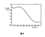
本発明の1つの例示的実施形態では、散逸パワーと散逸比のグラフは、本質的に逆相関ではなく、準ガウス曲線である。低い散逸比ではより大きいパワーを散逸することが望ましいことがあるが、そのような散逸は、利用可能な最大のパワー設定が使用される場合でさえ、低い散逸比により制限される。最も高い散逸比では、全く伝送しない(または非常にわずかしか伝送しない)ことが望ましいことがある。中間レベルは、どちらの傾向によっても影響を及ぼされ、したがって準ガウス形状である。 In one exemplary embodiment of the invention, the dissipation power versus dissipation ratio graph is a quasi-Gaussian curve rather than essentially an inverse correlation. While it may be desirable to dissipate more power at low dissipation ratios, such dissipation is limited by low dissipation ratios even when the maximum available power setting is used. At the highest dissipation ratio, it may be desirable to transmit no (or very little) transmission. The intermediate level is affected by either trend and is therefore quasi-Gaussian.
本発明の1つの例示的実施形態では、各周波数またはMSEが、1つまたは複数の負荷部分を表すと仮定する。負荷の同じ部分が複数の周波数またはMSEで吸収することがある。本発明の1つの例示的実施形態では、ある周波数またはMSEでの散逸が、それらの部分での散逸に対応すると仮定する。 In one exemplary embodiment of the invention, it is assumed that each frequency or MSE represents one or more load portions. The same part of the load may absorb at multiple frequencies or MSEs. In one exemplary embodiment of the invention, it is assumed that the dissipation at certain frequencies or MSEs corresponds to the dissipation at those parts.
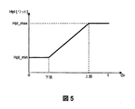
本発明の1つの例示的実施形態では、最大印加エネルギー(hpl)が、負荷のスペクトル情報に基づいて計算される。任意選択で、または別法として、周波数またはMSE毎のパワーレベルの選択は、そのような特性に従って選択される。任意選択で、または別法として、周波数またはMSE毎のパワーの選択は、より大きなパワーを負荷内に散逸させる周波数またはMSEのサブセットの選択に基づく。任意選択で、または別法として、各周波数またはMSEに関する、周波数またはMSE毎のパワーの選択は、その帯域のすべての周波数またはMSEで獲得されたスペクトル情報の分析に基づき、または、負荷に結合されているとみなされるすべての周波数またはMSE(例えば、例えば0.25%、または0.5%、または1%を超える高いQ値を有する帯域は含まない)で獲得されるスペクトル情報に基づく。 In one exemplary embodiment of the present invention, the maximum applied energy (hpl) is calculated based on the spectral information of the load. Optionally or alternatively, the selection of power level per frequency or MSE is selected according to such characteristics. Optionally or alternatively, the selection of power per frequency or MSE is based on the selection of a frequency or subset of MSEs that dissipate more power into the load. Optionally, or alternatively, the selection of power per frequency or MSE for each frequency or MSE is based on analysis of spectral information acquired at all frequencies or MSEs in that band or coupled to the load. Based on spectral information acquired at all frequencies or MSEs that are considered to be (eg, not including bands with high Q values greater than, for example, 0.25%, or 0.5%, or 1%).
本発明の1つの例示的実施形態では、解凍されている部分と解凍されていない部分を区別するためにスペクトル情報が分析される。任意選択で、そのような区別は、周波数毎またはMSE毎の分析ではなく、スペクトル情報の全般的な特性に基づき、例えば、氷と水の間でのスペクトル散逸画像の二峰性分布によって、予想される二峰性分布との合致に従って全体的に氷と水を分けることができると仮定する。時として、2つのモードの重なりがあり、そこでは、周波数またはMSEは、負荷の水部分と氷部分の両方である程度散逸する。 In one exemplary embodiment of the invention, the spectral information is analyzed to distinguish between the uncompressed part and the unthawed part. Optionally, such distinction is expected based on the general characteristics of the spectral information, rather than analysis by frequency or MSE, for example, by the bimodal distribution of the spectral dissipation image between ice and water. Suppose that ice and water can be separated as a whole according to the agreement with the bimodal distribution. Sometimes there is an overlap of the two modes, where the frequency or MSE is dissipated to some extent in both the water and ice portions of the load.
本発明の1つの例示的実施形態では、解凍プロトコルパラメータは、負荷サイズおよび/または体積に応じて決まり、例えば、解けた水/氷の含有量を推定する方法を補正する。この方法は、大きな標的のより大きな絶対氷含有量によって歪むことがあり、および/またはその初期温度が解凍温度に近い場合に歪むことがある。 In one exemplary embodiment of the present invention, the thawing protocol parameters depend on the load size and / or volume and correct, for example, how to estimate the melted water / ice content. This method may be distorted by the larger absolute ice content of the large target and / or may be distorted if its initial temperature is close to the thawing temperature.
本発明の1つの例示的実施形態では、含水量/高散逸周波数またはMSEの識別は、氷が水よりも低い散逸を有するという仮定に基づいている。任意選択で、そのような周波数またはMSEを検出するために、(相対または絶対)しきい値が使用される。任意選択で、しきい値は、比較的純粋な氷に関して提供され、それよりも上では、素材は、氷と水の混合物であると仮定される。任意選択で、システム全体は、負荷でない部分が非常に低い散逸を有するように、またはそこで散逸すると予想される周波数またはMSEにはエネルギーが全くまたはほとんど伝送されないように設計される。任意選択で、高いしきい値が提供され、それよりも上では、吸収材料が水であり、したがって低いパワーを伝送すべきであるか、またはパワーを伝送しないべきであり、負荷内へのパワー散逸を低くするか、またはなくす。任意選択で、中間散逸比の周波数またはMSEは、それらが水と氷の混合部分を反映するという仮定に基づいて追跡される。そのような部分は、完全に解凍されていることがあり、および/または水分が熱暴走事象を生じる中程度の危険がある。任意選択で、そのような中間周波数またはMSEは、中間パワーレベルを受け取る。 In one exemplary embodiment of the present invention, water content / high dissipation frequency or MSE identification is based on the assumption that ice has a lower dissipation than water. Optionally, a (relative or absolute) threshold is used to detect such a frequency or MSE. Optionally, a threshold is provided for relatively pure ice, above which the material is assumed to be a mixture of ice and water. Optionally, the entire system is designed so that the non-loaded portion has very low dissipation, or no or little energy is transmitted to the frequency or MSE that is expected to dissipate there. Optionally, a high threshold is provided, above which the absorbing material is water and therefore should transmit low power or should not transmit power and power into the load Reduce or eliminate dissipation. Optionally, intermediate dissipation ratio frequencies or MSEs are tracked based on the assumption that they reflect a mixed portion of water and ice. Such portions may be completely thawed and / or there is a moderate risk that moisture will cause a thermal runaway event. Optionally, such intermediate frequency or MSE receives an intermediate power level.
本発明の1つの例示的実施形態では、スペクトル情報に基づいて大きな氷が存在することを検出し、小さな氷の区域の示唆がスペクトル情報に現れ始めるまで、より大きなエネルギーをそれらの周波数またはMSEで提供することによって、大きな氷の区域(すべての周波数またはMSEで低い散逸を有する)が過補償されることはない(例えば、水であると仮定されて、したがって低いパワーを受け取ることはない)。例えば、中間散逸比を有する周波数またはMSEでのエネルギー伝送は、そのような周波数またはMSEが大きな氷を表す場合、高散逸比を有する周波数またはMSEのエネルギー伝送と同程度には減少されない。 One exemplary embodiment of the present invention detects the presence of large ice based on the spectral information and adds more energy at those frequencies or MSEs until an indication of a small ice area begins to appear in the spectral information. By providing, large ice areas (with low dissipation at all frequencies or MSEs) are not overcompensated (eg, assumed to be water and therefore not receive low power). For example, energy transmission at a frequency or MSE with an intermediate dissipation ratio is not reduced as much as energy transmission at a frequency or MSE with a high dissipation ratio if such frequency or MSE represents large ice.
本発明の1つの例示的実施形態では、これらおよび/または他のパラメータ、例えばしきい値、パワー/周波数の比、および時間は、負荷特性および/または所望の加熱効果に応じて決まる。任意選択で、様々なオプションを含むテーブルがメモリに記憶され、ユーザが選択することができる。任意選択で、または別法として、一連の関数が提供され、ユーザ選択または自動選択に従って適用される。 In one exemplary embodiment of the present invention, these and / or other parameters such as threshold, power / frequency ratio, and time are dependent on load characteristics and / or desired heating effects. Optionally, a table containing various options is stored in memory and can be selected by the user. Optionally or alternatively, a series of functions are provided and applied according to user selection or automatic selection.
任意選択で、または別法として、最大パワーレベルが、試行錯誤法を使用して、および/または負荷内の平均散逸の関数として計算される。 Optionally or alternatively, the maximum power level is calculated using trial and error methods and / or as a function of average dissipation in the load.
本発明の1つの例示的実施形態では、最大印加パワーレベルおよび/または周波数もしくはMSE依存パワーレベルが、解凍または他の加熱またはエネルギー印加プロセス中に更新される。任意選択で、この更新は、解凍プロセス中に複数回(例えば、実質上連続的に、例えば1000回/秒、または2回/秒、さらには5秒毎に1回、またはそれよりも長い間隔で)行われる。 In one exemplary embodiment of the invention, the maximum applied power level and / or the frequency or MSE dependent power level is updated during the thawing or other heating or energy application process. Optionally, this update may occur multiple times during the thawing process (eg, substantially continuously, eg, 1000 times / second, or 2 times / second, even once every 5 seconds, or longer intervals). Done).
本発明の1つの例示的実施形態では、走査の間の時間および/または走査の間の散逸は、過熱および/または熱暴走の危険を減少させるように選択される。任意選択で、使用されるパワーレベル、しきい値、走査レート、および/または他のパラメータは、回避すべきシナリオに応じて決まる。一例では、走査設定および/またはhplは、少量の水が誤って大量の氷とみなされた(したがって高パワーを照射された)場合に、次の走査が(氷と間違われていない場合の水の量の増加によって引き起こされる)そのような影響を検出するように選択される。 In one exemplary embodiment of the present invention, the time between scans and / or dissipation during the scans is selected to reduce the risk of overheating and / or thermal runaway. Optionally, the power level, threshold, scan rate, and / or other parameters used depend on the scenario to be avoided. In one example, the scan setting and / or hpl may be used to determine whether the next scan (if not mistaken for ice) should a small amount of water be mistakenly regarded as a large amount of ice (and thus irradiated with high power). Selected to detect such effects (caused by an increase in the amount of).
任意選択で、スペクトル情報を改良するため、例えば水を氷から区別するのを補助するために、負荷および/または空洞を操作する。これは、伝送に関するより高いパワーレベル(例えば平均)、および/またはより高い散逸比(例えば平均または最小)の計算を可能にすることがあり、したがって、十分な品質でより速い解凍を可能にする。例えば、空洞内での負荷の位置を変えることができ(例えば負荷が置かれたプレートを回転または振動させることによって)、スペクトル情報が複数の位置の間で比較される。任意選択で、獲得されるスペクトル情報が氷/水の区別に関して最も有用となる(例えば計算される最大のhplを有する)ように負荷が位置決めされた状態で、エネルギー伝送が行われる。 Optionally, the loads and / or cavities are manipulated to improve spectral information, eg, to help distinguish water from ice. This may allow calculation of higher power levels (eg, average) and / or higher dissipation ratio (eg, average or minimum) for transmission, thus allowing faster decompression with sufficient quality . For example, the position of the load within the cavity can be changed (eg, by rotating or vibrating the plate on which the load is placed) and the spectral information is compared between multiple positions. Optionally, energy transfer occurs with the load positioned such that the acquired spectral information is most useful for ice / water discrimination (eg, having the largest calculated hpl).
本発明の1つの例示的実施形態では、パワーが以前に印加された周波数またはMSEでは最小の低パワーレベルが散逸されて、そのような解凍済みの部分の冷却および/または再凍結を防止する。任意選択で、または別法として、スペクトル情報の第1の獲得と第2の獲得の間に所与の周波数またはMSEで負荷内に散逸させることができる最大パワーは、スペクトル情報の変化に基づいてパワーが停止される前に、解凍される部分が解凍段階をはるかに超えて加熱されることがないようなものである。 In one exemplary embodiment of the present invention, the lowest low power level is dissipated at the frequency or MSE where power was previously applied to prevent cooling and / or refreezing of such thawed portions. Optionally, or alternatively, the maximum power that can be dissipated in the load at a given frequency or MSE between the first acquisition and the second acquisition of spectral information is based on changes in the spectral information. It is such that the portion to be thawed is not heated far beyond the thaw stage before power is turned off.
本発明の1つの例示的実施形態では、正確な量のパワーを印加するのではなく、頻繁なフィードバックが使用される。任意選択で、または別法として、パワーを印加する方法は、使用されるパワー増幅器の特性を考慮する。 In one exemplary embodiment of the invention, frequent feedback is used rather than applying the exact amount of power. Optionally or alternatively, the method of applying power takes into account the characteristics of the power amplifier used.
本発明者らは、以下に詳述する可能性の1つまたは複数によって不均一な温度プロファイルが引き起こされる、または強調されることがあると仮説する。しかし、本明細書で述べる方法はまた、そのような仮説とは無関係に適用されることもあることに留意すべきである。さらに、本発明のいくつかの実施形態によれば、一様でない温度自体ではなく、負荷の有意な部分(例えば用途や使用者の望みに応じて、例えば0.1%、0.5%、1%、2%、5%、10%、または中間のパーセンテージ)の過熱または過熱の危険が防止されることに留意されたい。 We hypothesize that a non-uniform temperature profile may be caused or emphasized by one or more of the possibilities detailed below. However, it should be noted that the methods described herein may also be applied independently of such hypotheses. Further, according to some embodiments of the present invention, a significant portion of the load (eg, 0.1%, 0.5%, etc., depending on the application and the user's desire), rather than the uneven temperature itself. Note that the risk of overheating or overheating (1%, 2%, 5%, 10%, or an intermediate percentage) is prevented.
(a)不均一な組成。現実の負荷は、通常は異なる素材(例えば、ある鶏肉部位での脂肪、骨、皮膚、および筋肉、またはひき肉内部の空気ポケット、またはエビのパック内のエビの間の氷柱)を含み、これらは、異なる比熱(Cp)および/または異なる潜熱(L)を有する。そのような場合には、(RF加熱は通常、物体内部での伝導による熱移動よりも速いので)一様な散逸エネルギーは、不均一な温度をもたらすことがある。本発明のいくつかの実施形態によれば、そのような異なる素材に関連付けられる負荷部分に関するパワーレベルを決定するときに、(例えば予め設定されたテーブルを使用して)これが考慮に入れられる。 (A) Non-uniform composition. Real loads usually include different materials (eg, fat, bone, skin, and muscle at some chicken parts, or air pockets inside minced meat, or icicles between shrimp in shrimp packs) Have different specific heats (C p ) and / or different latent heats (L). In such cases, uniform dissipative energy can result in non-uniform temperatures (since RF heating is usually faster than heat transfer by conduction inside an object). According to some embodiments of the present invention, this is taken into account (eg, using a pre-set table) when determining the power level for the load portion associated with such different material.
(b)不均一な熱的状態および熱移動の挙動。負荷は、(最初に、または解凍中に)異なる部位で異なる温度を有することがある。これは、例えば以下のことに起因することがある。解凍開始前の非平衡な冷却(例えば、冷凍が不完全である場合には内側が外側よりも温かい。逆に、冷凍されている物体がそれ自体よりも高い温度に短時間さらされた場合には外側が内側よりも温かい);加熱前または加熱中の、異なる環境への負荷の表面の露出(場合によっては加熱中の、温かい空気、内部および外部の対流電流、冷たいプレートへの露出);上述したような異質の組成;負荷の不定形状(ある部分が他の部分よりも薄い);例えば異なる部分が異なる表面/体積比を有することがある負荷の不定形状;あるいは前述したことの2つ以上の組合せ。これにより、(負荷が100%均質であり、すべての部分へのエネルギー散逸が同一である場合でさえ)より低温の部分が相変化を始めるかなり前に、比較的温かい部分が相変化の過程を経ることがある。本発明の1つの例示的実施形態では、加熱プロトコルは、加熱中に、そのような一様でない温度および/または熱の散逸を考慮に入れる。任意選択で、そのような考慮は、氷部分に最大のパワーを向けることによって自動的に行われる。 (B) Non-uniform thermal state and heat transfer behavior. The load may have different temperatures at different sites (either initially or during thawing). For example, this may be caused by the following. Non-equilibrium cooling before thawing begins (for example, if the refrigeration is incomplete, the inside is warmer than the outside. Conversely, if the object being frozen is exposed to a temperature higher than itself for a short time. Is warmer on the outside than on the inside); exposure of the surface of the load to a different environment before or during heating (possibly heating, warm air, internal and external convection currents, exposure to cold plates); Heterogeneous composition as described above; load indefinite shape (some parts are thinner than others); for example, different portions may have different surface / volume ratios; or two of the above Combination of the above. This allows the relatively warmer part to undergo the phase change process long before the cooler part begins the phase change (even if the load is 100% homogeneous and the energy dissipation to all parts is the same). It may go through. In one exemplary embodiment of the invention, the heating protocol takes into account such uneven temperature and / or heat dissipation during heating. Optionally, such consideration is made automatically by directing maximum power to the ice part.
(c)温度依存加熱。多くのタイプの素材に関して、相変化を発生させるのに必要なエネルギーの量が相変化後の物質に印加される場合、かなりの温度上昇(例えば20、40、さらには80℃)を引き起こす。その結果、冷凍されている素材内でのエネルギーの均一な散逸は、より低温の部分で相変化が完了する前に、より高温の部分の過熱をもたらすことがある。本発明の1つの例示的実施形態では、そのような過熱は、過熱の影響を受けやすい領域、および/またはパワー/熱の比がより速い素材の加熱を示唆するような領域へのパワーを減少させることによって防止される。 (C) Temperature dependent heating. For many types of materials, when the amount of energy required to cause a phase change is applied to the material after the phase change, it causes a significant temperature rise (eg, 20, 40, or even 80 ° C.). As a result, the uniform dissipation of energy within the frozen material can lead to overheating of the hotter parts before the phase change is completed in the cooler parts. In one exemplary embodiment of the invention, such overheating reduces power to areas that are susceptible to overheating and / or areas where a power / heat ratio suggests faster heating of the material. To prevent it.
上記のことは、時として、相変化がある(例えば沸騰する)か、相変化がない(例えば負荷の温度が上昇する、および/または所望のレベルで温度が維持される)かに関わらず、解凍を伴わない負荷の加熱にも当てはまることがあることに留意されたい。 The above is sometimes true regardless of whether there is a phase change (eg, boiling) or no phase change (eg, the temperature of the load increases and / or the temperature is maintained at the desired level). Note that this may also apply to heating loads without thawing.
電磁エネルギーが印加される「物体」(「負荷」または「加熱対象の物体」とも呼ぶ)への言及は特定の形態に限定されないことに留意すべきである。「物体」または「負荷」は、本発明が利用される特定のプロセスに応じて、液体、固体、または気体を含むことがある。また、物体は、異なる相の物質からなる組成物または混合物を含むこともある。したがって、非限定的な例として、用語「物体」は、例えば以下のような物質を包含する。解氷または調理する食品;乾燥させる衣類または他の濡れた素材;解凍する凍結臓器;反応させる化学物質;燃焼させる燃料または他の可燃性材料;脱水する水和物;膨張させるガス;加熱、沸騰、または気化させる液体;またはわずかにでさえ電磁エネルギーを印加することが望まれる任意の他の素材。 It should be noted that references to “objects” (also referred to as “loads” or “objects to be heated”) to which electromagnetic energy is applied are not limited to a particular form. “Object” or “load” may include liquids, solids, or gases, depending on the particular process in which the invention is utilized. The object may also comprise a composition or mixture of substances of different phases. Thus, as a non-limiting example, the term “object” includes, for example, the following materials. Food to be deiced or cooked; clothes to dry or other wet materials; frozen organs to thaw; chemicals to react; fuels to burn or other combustible materials; hydrates to dehydrate; gases to expand; heating, boiling Or any other material where it is desired to apply electromagnetic energy, even slightly.
本発明の1つの例示的実施形態によれば、既に相変化した区域よりも相変化していない区域にかなり大きなRFエネルギーが散逸される場合に、一様でない加熱または少なくとも熱暴走が、少なくともある程度防止される。1つの特定の例は、解凍しない部分、脂肪、および/または他の凍結していない素材よりも、解凍される部分に大きなパワーを散逸することである。 According to one exemplary embodiment of the present invention, non-uniform heating or at least thermal runaway is at least to some extent when significant RF energy is dissipated in an area that has not changed phase than an already phase changed area. Is prevented. One particular example is dissipating more power in the thawed part than in non-thawed parts, fat, and / or other unfrozen material.
用語「RFまたは電磁エネルギー」は、本明細書で使用するとき、限定はせずに無線周波数(RF)、赤外線(IR)、近赤外線、可視光、紫外線などを含めた電磁スペクトルの任意の部分またはすべての部分を含むことに留意すべきである。1つの特定の例では、印加される電磁エネルギーは、100km〜1mmの自由空間内での波長(それぞれ3KHz〜300GHzの周波数)を有するRFエネルギーを含むことがある。いくつかの他の例では、周波数帯域は、500MHz〜1500MHzの間、または700MHz〜1200MHzの間、または800MHz〜1GHzの間でよい。例えば、マイクロ波エネルギーと超高周波数(UHF)エネルギーは、どちらもRF範囲内にある。本明細書では、本発明の例をRFエネルギーの印加に関連付けて説明するが、これらの説明は、本発明のいくつかの例示的な原理を示すために提示するものであり、電磁スペクトルの任意の特定の部分に本発明を限定することは意図されていない。 The term “RF or electromagnetic energy” as used herein refers to any part of the electromagnetic spectrum, including but not limited to radio frequency (RF), infrared (IR), near infrared, visible light, ultraviolet light, etc. Or it should be noted that all parts are included. In one particular example, the applied electromagnetic energy may include RF energy having a wavelength in free space of 100 km to 1 mm (frequency of 3 KHz to 300 GHz, respectively). In some other examples, the frequency band may be between 500 MHz and 1500 MHz, or between 700 MHz and 1200 MHz, or between 800 MHz and 1 GHz. For example, both microwave energy and ultra high frequency (UHF) energy are in the RF range. While the present invention will be described herein with reference to the application of RF energy, these descriptions are presented to illustrate some exemplary principles of the present invention and are intended to provide It is not intended that the invention be limited to any particular part of the invention.
本発明の1つの例示的実施形態では、エネルギー散逸のそのような不均一な分布は、比較的低い散逸比を有する周波数またはMSE、すなわち主に氷中で散逸する周波数またはMSEで高いパワーを伝送し、比較的高い散逸比を有する周波数またはMSE、すなわち主に水中で散逸する周波数またはMSEで低いパワーを伝送する(さらにはパワーを伝送しない)ことによって実現される。 In one exemplary embodiment of the invention, such a non-uniform distribution of energy dissipation transmits high power at a frequency or MSE with a relatively low dissipation ratio, ie, a frequency or MSE that dissipates primarily in ice. However, it is realized by transmitting low power (and not transmitting power) at a frequency or MSE having a relatively high dissipation ratio, that is, a frequency or MSE dissipating mainly in water.
本発明の例示的実施形態によれば、異なる負荷部分(例えば水および氷中、または例えば極性、脂質含量、および含水量を含めた任意の他の理由で異なる散逸比を有する負荷部分)での所与の周波数またはMSEの散逸は、多くの因子に依存し、それらの因子には、空洞内部の負荷組成、サイズ、形状、位置、および向き、ならびに異なる負荷部分での正確な温度および相が含まれることに留意されたい。異なる条件下では、所与の周波数またはMSEは、主に水中、主に氷中、またはその両方で散逸することがある。しかし、本発明者らは、空洞からスペクトル情報を取得すれば、取得した情報の分析を使用して有用な解凍プロトコルを導き出すことができること、および/またはそのような分析が、生じ得る水中および/または氷中での散逸のパターンを反映することができることを発見した。 According to exemplary embodiments of the present invention, at different load parts (eg, load parts having different dissipation ratios in water and ice or for any other reason including, for example, polarity, lipid content, and moisture content). The dissipation of a given frequency or MSE depends on many factors, including the load composition, size, shape, position, and orientation inside the cavity, as well as the exact temperature and phase at different load parts. Note that it is included. Under different conditions, a given frequency or MSE may dissipate mainly in water, primarily in ice, or both. However, we can obtain spectral information from the cavity and use the analysis of the acquired information to derive useful thawing protocols and / or underwater and / or such analysis can occur. Or found that it can reflect the pattern of dissipation in ice.
本出願の文脈では、用語「スペクトル情報」は、異なる周波数またはMSEでの、および/またはチャンバ内の負荷との、チャンバ内におけるRFの相互作用データを意味し、例えば、一度に1つまたは複数の空洞内供給機構を使用して、一定のパワーまたは変化するパワーで周波数またはMSEをスイープし、前記1つまたは複数の空洞内供給機構によって受信される反射パワーを測定し、任意選択で、各周波数またはMSEで空洞内に実際に伝送されたパワーを考慮する。時として、1つの供給機構が伝送し、1つまたは複数の他の供給機構(またはすべての他の供給機構)が、反射されたパワーを測定する。時として、このプロセスは、複数の供給機構の1つまたは複数に関して繰り返される。非限定的な例は、国際公開第07/096878号パンフレットに記載されるようなスペクトル画像の取得である。 In the context of the present application, the term “spectral information” means RF interaction data in a chamber at different frequencies or MSEs and / or with loads in the chamber, eg one or more at a time. A frequency or MSE with constant or varying power, and measuring the reflected power received by the one or more intracavity delivery mechanisms, optionally Consider the power actually transmitted into the cavity at frequency or MSE. Sometimes one feed mechanism transmits and one or more other feed mechanisms (or all other feed mechanisms) measure the reflected power. Sometimes this process is repeated for one or more of the plurality of delivery mechanisms. A non-limiting example is the acquisition of spectral images as described in WO 07/096878.
本発明の1つの例示的実施形態では、制約関数を使用して、比較的高い散逸比を有する部分にはより少量のエネルギーが散逸し(またはエネルギーが全く散逸せず)、一方、比較的低い散逸比を有する部分にはより多量のエネルギーが散逸するように空洞内に伝送するためにRFパワーを計算する。本発明の1つの例示的実施形態では、高い散逸比を有する部分では、低い散逸比または中間の散逸比を有する部分よりも単位体積当たりに散逸されるエネルギー(または単位質量当たりの散逸)が小さくなるように関数が選択される。本発明の1つの例示的実施形態では、制約関数を使用して、比較的高い散逸比を有する周波数またはMSEによってより少量のエネルギーが負荷内に散逸し(またはエネルギーが全く散逸せず)、一方、比較的低い散逸比を有する周波数またはMSEによってより多量のエネルギーが負荷内に散逸するように、空洞内に伝送するためにRFパワーを計算する。本発明の1つの例示的実施形態では、解凍(または部分解凍)され(または負荷内への周波数またはMSEの散逸比が増加し)、その後、「高散逸部分(または周波数もしくはMSE)」(または「中間散逸部分(または周波数もしくはMSE)」)として分類し直される負荷の部分に関して、加熱が自動的におよび/または本来的に調節される。例えば、加熱セッション後に周波数またはMSE走査またはスイープを行うことによって、使用される周波数またはMSEの少なくともいくつかの散逸比の変化が見られるようになることがあり、この変化は、少なくとも一部には、負荷のそれぞれの部分の相変化と相関する。新たに獲得されたスペクトル情報に基づいて伝送プロトコルを再計算することによって、デバイスは、解凍の進行(および/または動作中に負荷が移動する場合には負荷の位置の変化)に関して自己調節することができる。 In one exemplary embodiment of the present invention, a constraint function is used to dissipate less energy (or no energy at all) in a portion having a relatively high dissipation ratio, while relatively low The RF power is calculated for transmission into the cavity so that a larger amount of energy is dissipated in the part having the dissipation ratio. In one exemplary embodiment of the invention, a portion with a high dissipation ratio will dissipate less energy (or dissipation per unit mass) per unit volume than a portion with a low or intermediate dissipation ratio. The function is selected so that In one exemplary embodiment of the invention, a constraint function is used to dissipate less energy into the load (or no energy is dissipated) due to frequencies or MSEs having a relatively high dissipation ratio, while Calculate the RF power for transmission into the cavity so that a greater amount of energy is dissipated in the load by the frequency or MSE having a relatively low dissipation ratio. In one exemplary embodiment of the invention, it is thawed (or partially thawed) (or the frequency or MSE dissipation ratio into the load is increased) and then "highly dissipated part (or frequency or MSE)" (or With respect to the part of the load that is reclassified as “intermediate dissipation part (or frequency or MSE)”), the heating is adjusted automatically and / or inherently. For example, performing a frequency or MSE scan or sweep after a heating session may result in a change in the used frequency or at least some dissipation ratio of the MSE, this change being at least in part Correlate with the phase change of each part of the load. By recalculating the transmission protocol based on newly acquired spectral information, the device will self-tune with respect to the progress of thawing (and / or the change in load position if the load moves during operation) Can do.
本発明の1つの例示的実施形態では、各周波数またはMSEでの伝送エネルギーは、高い散逸比(例えば70%以上または80%以上)を有する周波数またはMSEで負荷内に散逸するエネルギーの量を、比較的低い散逸比(例えば40%以下または30%以下)を有する周波数またはMSEで負荷内に散逸されるエネルギーの50%以下にすることができるように選択される。時として、これは、低い散逸比を有する周波数またはMSEで散逸されるエネルギーの20%以下、5%以下、0.1%以下、さらには0%となる。 In one exemplary embodiment of the present invention, the transmitted energy at each frequency or MSE is the amount of energy dissipated in the load at a frequency or MSE with a high dissipation ratio (eg, 70% or more or 80% or more), It is selected so that it can be 50% or less of the energy dissipated in the load at a frequency or MSE with a relatively low dissipation ratio (eg 40% or less or 30% or less). Sometimes this will be 20% or less, 5% or less, 0.1% or less, or even 0% of the energy dissipated in a frequency or MSE with a low dissipation ratio.
上述したことは解凍に焦点を当てているが、他の相変化にも適用することができ、あるいは、パワー散逸と加熱率の関係が突然変化する状況、および/または熱暴走を防止することが望まれる状況(例えば、それぞれ高い比熱と低い比熱および/または高い潜熱と低い潜熱に対応する、低い散逸比の区域と高い散逸比の区域の両方を含む物体を均一に加熱することを試みるとき)にも適用することができる。さらに、異なる条件で加熱される複数の(例えば3つ、4つ、5つ、またはそれよりも多い)部分が提供されることもある。時として、加熱に使用される作業帯域の複数の部分は、エネルギーが伝送されない周波数またはMSE(または一部)を含まない。任意選択で、異なる周波数またはMSEが、散逸比に基づいてそのような複数の部分に割り当てられる。しかし、温度変化に必要なエネルギーに比べて相変化に必要なエネルギー量が大きいことに起因して、また、食品がしばしば冷凍保存されており、解凍して提供または用意されることを考慮して、解凍が特に興味深い要点となることに留意されたい。同様に、追加として、または別法として、過熱によって損傷を受けることがある部分および/または十分に加熱されていない場合には容認できない部分が対象となることがある。時として、任意の他の理由から、異なる部分を異なる条件で加熱することが望ましいことがある(例えば、1つの部分を加熱(例えば調理)するが別の部分は調理しない、または異なる最終温度に達する)。 The above has focused on thawing, but can also be applied to other phase changes, or to prevent situations where the relationship between power dissipation and heating rate changes suddenly and / or thermal runaway. The desired situation (for example, when attempting to uniformly heat an object containing both low and high dissipation ratio areas, corresponding to high and low specific heat and / or high and low latent heat, respectively) It can also be applied to. In addition, multiple (eg, three, four, five, or more) portions may be provided that are heated at different conditions. Sometimes, the portions of the work zone used for heating do not include frequencies or MSEs (or portions) where energy is not transmitted. Optionally, different frequencies or MSEs are assigned to such multiple parts based on dissipation ratio. However, due to the large amount of energy required for phase change compared to the energy required for temperature change, and considering that food is often stored frozen and served or prepared by thawing Note that thawing is a particularly interesting point. Similarly, portions that may or may not be damaged by overheating and / or portions that are unacceptable if not sufficiently heated may be covered. Occasionally, for any other reason, it may be desirable to heat different parts at different conditions (eg, heating one part (eg, cooking) but not another part), or to a different final temperature. Reach).
また、いくつかの実施形態において根底にあるストラテジは、標的となる負荷部分に対するそのようなパワーの効果に従って単位体積当たりのパワーを調整することであるが、いくつかの実施形態によれば、これは、特定の周波数またはMSEに狙いを定め、それらの周波数またはMSEの散逸に従ってパワーを調整することによって直接実現され、単位体積当たりでの特定のパワーレベルを直接は保証しないことにも留意されたい。 Also, in some embodiments, the underlying strategy is to adjust the power per unit volume according to the effect of such power on the target load portion, but according to some embodiments this is Note also that is achieved directly by targeting specific frequencies or MSEs and adjusting the power according to the dissipation of those frequencies or MSEs, and does not directly guarantee a specific power level per unit volume. .
本発明の1つの例示的実施形態によれば、RFを使用して負荷を加熱する方法において、
(a)過熱温度点を有する負荷を提供するステップと、
(b)過熱を防止するように、負荷に散逸すべき最大のパワーを選択するステップと、
(c)複数の異なる周波数またはMSEでRFパワーを前記負荷に印加するステップであって、前記パワーが、異なる周波数またはMSEでは異なり、すべての周波数またはMSEで前記最大パワー未満であるステップと
を含む方法が提供される。
According to one exemplary embodiment of the present invention, in a method of heating a load using RF,
(A) providing a load having a superheat temperature point;
(B) selecting the maximum power to be dissipated to the load to prevent overheating;
(C) applying RF power to the load at a plurality of different frequencies or MSEs, wherein the power is different at different frequencies or MSEs and less than the maximum power at all frequencies or MSEs A method is provided.
本発明の1つの例示的実施形態では、前記選択するステップは、加熱の均一性と加熱の速度との折り合い点を見出すステップを含む。時として、選択される最大パワーは、任意の所与の周波数またはMSEでデバイスによって利用可能な最大パワーに、その周波数またはMSEでの散逸比を乗算したものでよい。任意選択で、または別法として、RFパワーを印加するステップが、前記負荷の相変化をもたらすステップを含む。任意選択で、前記相変化は解凍を含む。別法として、前記相変化は蒸発を含む。 In one exemplary embodiment of the invention, the selecting step includes finding a compromise between heating uniformity and heating rate. Sometimes the maximum power selected may be the maximum power available by the device at any given frequency or MSE multiplied by the dissipation ratio at that frequency or MSE. Optionally or alternatively, applying RF power includes providing a phase change of the load. Optionally, the phase change includes thawing. Alternatively, the phase change includes evaporation.
本発明の1つの例示的実施形態では、前記相変化は、負荷の1単位部分の相変化を引き起こすためのパワーの効果と、相変化が完了している負荷の1単位部分の温度を1℃だけ上昇させるためのパワーの効果との比が少なくとも1:20である。 In one exemplary embodiment of the present invention, the phase change includes the effect of power to cause a phase change in a unitary part of the load and the temperature of the unitary part of the load where the phase change is complete at 1 ° C. The ratio to the effect of power to increase only by at least 1:20.
本発明の1つの例示的実施形態では、前記パワーは、前記印加中に前記負荷内の熱暴走を防止するように選択されて印加される。 In one exemplary embodiment of the present invention, the power is selected and applied to prevent thermal runaway in the load during the application.
本発明の1つの例示的実施形態では、最大パワーを選択するステップが、負荷の平均散逸の関数として最大パワーを選択するステップを含む。 In one exemplary embodiment of the present invention, selecting the maximum power includes selecting the maximum power as a function of the average dissipation of the load.
本発明の1つの例示的実施形態では、最大パワーを選択するステップが、負荷のスペクトル情報の関数として最大パワーを選択するステップを含む。 In one exemplary embodiment of the invention, selecting the maximum power includes selecting the maximum power as a function of the spectral information of the load.
本発明の1つの例示的実施形態では、方法は、パワーが印加される周波数またはMSEで印加できる最小パワーを選択するステップを含む。 In one exemplary embodiment of the invention, the method includes selecting a frequency at which power is applied or a minimum power that can be applied at the MSE.
本発明の1つの例示的実施形態では、方法は、前記複数の周波数またはMSEそれぞれに関してパワーを選択するステップを含む。任意選択で、パワーを選択するステップは、前記RFパワーを印加するために使用されるシステムのより広い帯域幅内で、パワーに関する1つまたは複数の周波数サブバンドを選択するステップを含む。 In one exemplary embodiment of the invention, the method includes selecting power for each of the plurality of frequencies or MSEs. Optionally, selecting power includes selecting one or more frequency subbands for power within a wider bandwidth of the system used to apply the RF power.
本発明の1つの例示的実施形態では、方法は、前記負荷のスペクトル情報を繰り返し検索し、前記情報を使用して、前記選択するステップおよび前記印加するステップの少なくとも一方を進めるステップを含む。 In one exemplary embodiment of the present invention, the method includes iteratively retrieving spectral information of the load and using the information to advance at least one of the selecting and applying.
本発明の1つの例示的実施形態では、前記RFパワーを印加するステップが、ある周波数での散逸比に対して逆比となるパワーを前記周波数で印加するステップを含む。 In one exemplary embodiment of the invention, applying the RF power includes applying power at the frequency that is inverse to the dissipation ratio at a frequency.
本発明の1つの例示的実施形態では、方法は、低いしきい値レベル未満の散逸比を有する周波数でのパワーの印加を回避するステップを含む。 In one exemplary embodiment of the invention, the method includes avoiding application of power at frequencies having a dissipation ratio below a low threshold level.
本発明の1つの例示的実施形態では、方法は、高いしきい値レベルを超える散逸比を有する周波数でのパワーの印加を回避するステップを含む。 In one exemplary embodiment of the invention, the method includes avoiding application of power at a frequency having a dissipation ratio that exceeds a high threshold level.
本発明の1つの例示的実施形態では、前記印加するステップは、前記負荷内の氷を識別するステップに応答し、前記識別するステップは、低い散逸を有する周波数に従って識別するステップを含む。任意選択で、識別するステップは、負荷の質量に関して補償される。任意選択で、または別法として、識別するステップは、負荷タイプに応じて決まるしきい値に従う。 In one exemplary embodiment of the invention, the applying step is responsive to identifying ice in the load, and the identifying step includes identifying according to a frequency having low dissipation. Optionally, the identifying step is compensated for the mass of the load. Optionally or alternatively, the identifying step follows a threshold that depends on the load type.
本発明による1つの例示的実施形態によれば、先行する請求項の任意のものの選択ステップおよび印加ステップを実施するように構成された装置が提供される。 According to one exemplary embodiment according to the present invention, there is provided an apparatus configured to perform the selection and application steps of any of the preceding claims.
本発明の1つの例示的実施形態によれば、RFを使用して負荷を加熱する方法において、
(a)異なる部分で異なる散逸比を有する負荷を提供するステップと、
(b)負荷の加熱時に、第1の散逸比で散逸する周波数では、第2の散逸比で散逸する周波数よりも小さいエネルギー(またはパワー)が伝送されるように、周波数/エネルギー対を設定するステップであって、前記第2の散逸比が、所与の伝送サイクルで前記第1の散逸比よりも高いステップと、
(c)前記負荷を加熱するために前記周波数/パワー対を適用するステップと
を含む方法が提供される。
According to one exemplary embodiment of the present invention, in a method of heating a load using RF,
(A) providing loads having different dissipation ratios in different parts;
(B) When the load is heated, the frequency / energy pair is set so that the energy dissipated at the first dissipation ratio transmits less energy (or power) than the frequency dissipated at the second dissipation ratio. Steps wherein the second dissipation ratio is higher than the first dissipation ratio in a given transmission cycle;
(C) applying the frequency / power pair to heat the load.
本発明の1つの例示的実施形態によれば、RFを使用して負荷を加熱する方法において、
(a)異なる部分で、印加される伝送エネルギー(h/te)当たり異なる加熱率を有する負荷を提供するステップと、
(b)負荷の加熱時に、高いh/te率を有する部分に対応する周波数で、低いh/teを有する部分に対応する周波数よりも、部分の単位体積当たりに小さいエネルギーが伝送されるように、周波数/エネルギー対を設定するステップと、
(c)前記負荷を加熱するために前記周波数/パワー対を適用するステップと
を含む方法が提供される。
According to one exemplary embodiment of the present invention, in a method of heating a load using RF,
(A) providing loads having different heating rates per applied transmission energy (h / te) in different parts;
(B) When heating the load, at a frequency corresponding to a portion having a high h / te rate, a smaller energy is transmitted per unit volume of the portion than a frequency corresponding to a portion having a low h / te. Setting a frequency / energy pair;
(C) applying the frequency / power pair to heat the load.
本発明の1つの例示的実施形態によれば、RFを使用して負荷を加熱する方法において、
(a)異なる部分で異なる散逸比を有する負荷を提供するステップと、
(b)負荷の加熱時に、第1の散逸比で散逸する周波数と第2の散逸比で散逸する周波数で異なるパワー印加プロトコルが適用されるように、周波数/パワー対を設定するステップと、
(c)前記負荷を加熱するために前記周波数/パワー対を適用するステップと
を含む方法が提供される。
According to one exemplary embodiment of the present invention, in a method of heating a load using RF,
(A) providing loads having different dissipation ratios in different parts;
(B) setting the frequency / power pair such that, during heating of the load, different power application protocols are applied at the frequency dissipating at the first dissipation ratio and the frequency dissipating at the second dissipation ratio;
(C) applying the frequency / power pair to heat the load.
本発明の1つの例示的実施形態では、前記印加するステップは、より低い散逸比を有する部分に関してより大きなパワーを印加するステップを含む。任意選択で、または別法として、2つ以上のパワー印加プロトコルの相違は、それぞれの負荷部分で散逸すべき負荷量当たりのエネルギーの総量を含む。任意選択で、または別法として、2つ以上のパワー印加プロトコルの相違は、加熱速度と均質性との折り合い点を含む。 In one exemplary embodiment of the invention, the applying step includes applying more power for a portion having a lower dissipation ratio. Optionally, or alternatively, the difference between the two or more power application protocols includes the total amount of energy per load to be dissipated in each load portion. Optionally or alternatively, the difference between the two or more power application protocols includes a compromise between heating rate and homogeneity.
本発明の1つの例示的実施形態では、前記設定するステップは、散逸比に関連付けられるセットに周波数を関連付けるステップを含み、前記設定するステップは、前記セットに従って周波数/パワー対を選択するステップを含む。任意選択で、前記設定するステップは、セット当たりのパワーレベルを選択するステップを含む。任意選択で、または別法として、前記関連付けるステップは、前記散逸比に加えて情報に基づいて関連付けるステップを含む。任意選択で、または別法として、少なくとも1つのセットは、複数の不連続な周波数範囲を含み、前記範囲の間で少なくとも1つの周波数が別のセットに属する。任意選択で、または別法として、少なくとも1つのセットは、冷凍されている素材に対応する。任意選択で、または別法として、関連付けるステップは、少なくとも3つのセットに関連付けるステップを含む。任意選択で、または別法として、前記周波数またはMSEをセットに関連付けるステップは、所定の数のセットに関連付けることによって行われる。任意選択で、前記所定の数のセットは、2〜10セットである。 In one exemplary embodiment of the invention, the step of configuring includes associating a frequency with a set associated with a dissipation ratio, and the step of configuring includes selecting a frequency / power pair according to the set. . Optionally, the step of setting includes selecting a power level per set. Optionally or alternatively, the associating step includes associating based on information in addition to the dissipation ratio. Optionally or alternatively, the at least one set includes a plurality of discrete frequency ranges, and at least one frequency between the ranges belongs to another set. Optionally or alternatively, at least one set corresponds to the material being frozen. Optionally or alternatively, associating includes associating with at least three sets. Optionally, or alternatively, associating the frequency or MSE with a set is performed by associating with a predetermined number of sets. Optionally, the predetermined number of sets is 2-10 sets.
本発明の1つの例示的実施形態では、関連付けるステップは、複数の周波数またはMSEに割り当てられた有意な量の散逸エネルギーまたはパワーをそれぞれ有する少なくとも2つのセットに関連付けるステップを含み、前記有意な量は、セットに割り当てられる加熱サイクル中の総散逸パワーの少なくとも7%である。任意選択で、または別法として、前記セットの少なくとも2つは、非ゼロ伝送パワーを有し、1つのセットの平均散逸パワーは、別のセットの少なくとも2倍である。任意選択で、または別法として、前記セットの少なくとも2つは、非ゼロ伝送パワーを有し、1つのセットの平均散逸パワーは、別のセットの少なくとも5倍である。任意選択で、または別法として、前記セットの少なくとも2つは、非ゼロ伝送パワーを有し、1つのセットの平均散逸パワーは、別のセットの少なくとも10倍である。任意選択で、または別法として、パワーが伝送されるセットは、作業周波数またはMSEの少なくとも5%をカバーする。任意選択で、または別法として、パワーが伝送されるセットは、作業周波数またはMSEの少なくとも20%をカバーする。任意選択で、または別法として、前記セットの少なくとも2つは、それぞれ、散逸比の値範囲の少なくとも10%に対応する。 In one exemplary embodiment of the invention, associating comprises associating with at least two sets each having a significant amount of dissipated energy or power assigned to multiple frequencies or MSEs, wherein the significant amount is , At least 7% of the total dissipated power during the heating cycle assigned to the set. Optionally or alternatively, at least two of the sets have non-zero transmit power, and the average dissipated power of one set is at least twice that of another set. Optionally or alternatively, at least two of the sets have non-zero transmit power and the average dissipated power of one set is at least five times that of another set. Optionally or alternatively, at least two of the sets have non-zero transmit power and the average dissipated power of one set is at least 10 times that of another set. Optionally or alternatively, the set in which power is transmitted covers at least 5% of the working frequency or MSE. Optionally or alternatively, the set in which power is transmitted covers at least 20% of the working frequency or MSE. Optionally or alternatively, at least two of the sets each correspond to at least 10% of the value range of dissipation ratio.
本発明の1つの例示的実施形態では、前記負荷が食品を含む。任意選択で、または別法として、前記負荷は、少なくとも2つの食品部分の組合せを含む。任意選択で、または別法として、前記印加するステップは、前記負荷の相変化を引き起こす。任意選択で、または別法として、前記印加するステップは、前記負荷の少なくとも一部の解凍を引き起こす。 In one exemplary embodiment of the invention, the load includes food. Optionally or alternatively, the load comprises a combination of at least two food parts. Optionally or alternatively, the applying step causes a phase change of the load. Optionally or alternatively, the applying step causes thawing of at least a portion of the load.
本発明の1つの例示的実施形態では、方法は、加熱プロセスの一部として、ステップ(b)および(c)を少なくとも2回繰り返すステップを含む。 In one exemplary embodiment of the invention, the method includes repeating steps (b) and (c) at least twice as part of the heating process.
また、本発明の1つの例示的実施形態によれば、RFを使用して負荷を加熱する方法において、
(a)異なる部分で、印加されるパワー当たりの異なる加熱率(h/p)を有する負荷を提供するステップと、
(b)負荷の加熱時に、高いh/p率を有する部分に対応する周波数で、低いh/pを有する部分に対応する周波数よりも、部分の単位体積当たりに小さいエネルギーが伝送されるように、周波数/パワー対を設定するステップと、
(c)前記負荷を加熱するために前記周波数/パワー対を適用するステップと
を含む方法が提供される。
Also according to one exemplary embodiment of the present invention, in a method of heating a load using RF,
(A) providing loads having different heating rates (h / p) per applied power in different parts;
(B) When heating the load, at a frequency corresponding to a portion having a high h / p ratio, less energy is transmitted per unit volume of the portion than at a frequency corresponding to a portion having a low h / p. Setting a frequency / power pair;
(C) applying the frequency / power pair to heat the load.
また、本発明による1つの例示的実施形態によれば、先行する請求項の任意のものの選択ステップおよび印加ステップを実施するように構成された装置が提供される。任意選択で、装置は、複数のパワー印加プロトコルを記憶し、異なる周波数セットに異なるプロトコルを適用するように構成されたメモリを備える。 Also, according to one exemplary embodiment according to the present invention, there is provided an apparatus configured to perform the selection and application steps of any of the preceding claims. Optionally, the apparatus comprises a memory configured to store a plurality of power application protocols and apply different protocols to different frequency sets.
また、本発明の1つの例示的実施形態によれば、RFを使用して負荷を加熱する方法において、
(a)過熱温度点を有する負荷を提供するステップと、
(b)過熱を防止するように、負荷に散逸すべき最大のパワーを選択するステップと、
(c)複数の異なる周波数でRFパワーを前記負荷に印加するステップであって、前記パワーが、異なる周波数では異なり、すべての周波数で前記最大パワー未満であるステップと
を含む方法が提供される。任意選択で、RWパワーを印加するステップが、前記負荷の相変化をもたらすステップを含む。任意選択で、前記相変化は解凍を含む。任意選択で、または別法として、前記相変化は蒸発を含む。
Also according to one exemplary embodiment of the present invention, in a method of heating a load using RF,
(A) providing a load having a superheat temperature point;
(B) selecting the maximum power to be dissipated to the load to prevent overheating;
(C) applying RF power to the load at a plurality of different frequencies, wherein the power is different at different frequencies and less than the maximum power at all frequencies. Optionally, applying RW power includes providing a phase change of the load. Optionally, the phase change includes thawing. Optionally or alternatively, the phase change includes evaporation.
本発明の1つの例示的実施形態では、前記相変化は、負荷部分1単位当たりの相変化を引き起こすためのパワーの効果と、相変化が完了している負荷部分1単位当たりの温度を1℃だけ上昇させるためのパワーの効果との比が少なくとも1:20である。 In one exemplary embodiment of the present invention, the phase change comprises the effect of power to cause a phase change per unit of load portion and the temperature per unit of load portion at which the phase change is complete is 1 ° C. The ratio to the effect of power to increase only by at least 1:20.
本発明の1つの例示的実施形態では、前記パワーは、前記印加中に前記負荷内の熱暴走を防止するように選択されて印加される。任意選択で、または別法として、最大パワーを選択するステップが、負荷の平均散逸の関数として最大パワーを選択するステップを含む。任意選択で、または別法として、最大パワーを選択するステップが、負荷のスペクトル情報の関数として最大パワーを選択するステップを含む。任意選択で、または別法として、最大パワーを選択するステップが、任意の所与の周波数で空洞内にデバイスによって伝送させることができる最大パワーの関数として最大パワーを選択するステップを含む。 In one exemplary embodiment of the present invention, the power is selected and applied to prevent thermal runaway in the load during the application. Optionally or alternatively, selecting the maximum power includes selecting the maximum power as a function of the average dissipation of the load. Optionally or alternatively, selecting the maximum power includes selecting the maximum power as a function of the spectral information of the load. Optionally or alternatively, selecting the maximum power includes selecting the maximum power as a function of the maximum power that can be transmitted by the device in the cavity at any given frequency.
本発明の1つの例示的実施形態では、方法は、パワーが印加される周波数またはMSEで印加できる最小パワーを選択するステップを含む。任意選択で、または別法として、方法は、前記複数の周波数またはMSEそれぞれに関してパワーを選択するステップを含む。任意選択で、パワーを選択するステップは、前記RFパワーを印加するために使用されるシステムのより広い帯域幅内で、パワーに関する1つまたは複数の周波数またはMSEサブバンドを選択するステップを含む。 In one exemplary embodiment of the invention, the method includes selecting a frequency at which power is applied or a minimum power that can be applied at the MSE. Optionally or alternatively, the method includes selecting power for each of the plurality of frequencies or MSEs. Optionally, selecting power includes selecting one or more frequencies or MSE subbands for power within a wider bandwidth of the system used to apply the RF power.
本発明の1つの例示的実施形態では、方法は、前記負荷のスペクトル情報を検索し、前記情報を使用して、前記選択するステップおよび前記印加するステップの少なくとも一方を進めるステップを含む。任意選択で、スペクトル情報の前記検索が繰り返し行われる。 In one exemplary embodiment of the present invention, the method includes retrieving spectral information of the load and using the information to advance at least one of the selecting and applying. Optionally, the search for spectral information is repeated.
本発明の1つの例示的実施形態では、前記RFパワーを印加するステップが、ある周波数またはMSEでの散逸に対して逆相関するパワーを前記周波数またはMSEで印加するステップを含む。 In one exemplary embodiment of the invention, applying the RF power includes applying power at the frequency or MSE that is inversely correlated to dissipation at a frequency or MSE.
本発明の1つの例示的実施形態では、方法は、低いしきい値レベル未満の散逸比を有する周波数またはMSEでのパワーの印加を回避するステップを含む。 In one exemplary embodiment of the invention, the method includes avoiding application of power at a frequency or MSE having a dissipation ratio below a low threshold level.
本発明の1つの例示的実施形態では、方法は、高いしきい値レベルよりも上の散逸比を有する周波数またはMSEでのパワーの印加を回避するステップを含む。 In one exemplary embodiment of the invention, the method includes avoiding application of power at a frequency or MSE having a dissipation ratio above a high threshold level.
本発明の1つの例示的実施形態では、前記印加するステップは、前記負荷内の氷を識別するステップに応答し、前記識別するステップは、低い散逸を有する周波数またはMSEに従って識別するステップを含む。任意選択で、識別するステップは、負荷の質量に関して補償される。任意選択で、または別法として、識別するステップは、負荷タイプに応じて決まるしきい値に従う。 In one exemplary embodiment of the invention, the applying step is responsive to identifying ice in the load, the identifying step comprising identifying according to a frequency or MSE with low dissipation. Optionally, the identifying step is compensated for the mass of the load. Optionally or alternatively, the identifying step follows a threshold that depends on the load type.
本発明の1つの例示的実施形態では、前記印加するステップが、散逸比の値の正規化を含む。 In one exemplary embodiment of the invention, the applying step includes normalizing the dissipation ratio value.
本発明の1つの例示的実施形態では、パワーを印加するステップが、所与の期間に異なる合計量のパワーを印加することを含み、それにより、特定の周波数またはMSEに関する実際のパワーは一定であるが、期間内でのパワーの印加の時間間隔が周波数またはMSE毎に変えられ、異なる周波数またはMSEに関する異なる実効合計パワーを生み出す。 In one exemplary embodiment of the invention, the step of applying power includes applying different total amounts of power in a given period, so that the actual power for a particular frequency or MSE is constant. Although, the time interval of application of power within a period is varied for each frequency or MSE, producing different effective total powers for different frequencies or MSEs.
本発明の1つの例示的実施形態では、パワーを印加するステップは、複数の前記周波数またはMSEを複数のセットにグループ化し、セット当たりの印加パワーに基づいて、印加されるパワーの量を変えるステップを含む。 In one exemplary embodiment of the present invention, applying power includes grouping a plurality of said frequencies or MSEs into a plurality of sets and varying the amount of power applied based on the applied power per set. including.
本開示では、概念の多くを、周波数および/または変調空間要素に関連付けて説明してきた。いくつかの実施形態では、周波数が、変調空間要素を定義または操作するために使用される1つまたは複数のパラメータの中に含まれることがある。したがって、一般に、周波数に関して説明する本明細書で開示する実施形態に関係する概念はまた、より一般的に、変調空間要素の使用を含む実施形態に拡張することができる。 In this disclosure, many of the concepts have been described in relation to frequency and / or modulation spatial elements. In some embodiments, the frequency may be included in one or more parameters used to define or manipulate the modulation spatial element. Thus, in general, the concepts related to the embodiments disclosed herein that are described in terms of frequency can also be extended to embodiments that more generally involve the use of modulation spatial elements.
いくつかの例示的実施形態は、EMエネルギーを負荷に印加するための装置を含むことがある。装置は、少なくとも1つの処理装置を含むことができ、処理装置が、複数の変調空間要素それぞれに関する散逸エネルギーを示唆する情報を受信し、散逸エネルギーを示唆する受信された情報に基づいて、いくつかの複数の変調空間要素を少なくとも2つのサブセットにグループ化するように構成される。また、処理装置は、パワー送達プロトコルを少なくとも2つのサブセットそれぞれに関連付け、その際、パワー送達プロトコルがサブセット間で異なり、さらに、各パワー送達プロトコルに従って負荷に印加されるエネルギーを調整するように構成することができる。 Some exemplary embodiments may include an apparatus for applying EM energy to a load. The apparatus can include at least one processing unit, wherein the processing unit receives information suggesting dissipated energy for each of the plurality of modulation spatial elements, and based on the received information suggesting dissipated energy, Are configured to be grouped into at least two subsets. The processing device also associates a power delivery protocol with each of the at least two subsets, wherein the power delivery protocols are different between the subsets and further configured to regulate the energy applied to the load according to each power delivery protocol. be able to.
他の例示的実施形態は、EMエネルギーを負荷に印加するための方法を含むことがある。この方法は、複数の変調空間要素それぞれに関して、散逸エネルギーを示唆する情報を受信するステップと、散逸エネルギーを示唆する受信された情報に基づいて、いくつかの複数の変調空間要素を、少なくとも2つのサブセットにグループ化するステップと、パワー送達プロトコルを少なくとも2つのサブセットそれぞれに関連付けるステップであって、パワー送達プロトコルがサブセット毎に異なるステップと、各パワー送達プロトコルに従って負荷に印加されるエネルギーを調整するステップとを含むことができる。 Other exemplary embodiments may include a method for applying EM energy to a load. The method includes, for each of the plurality of modulation spatial elements, receiving information indicative of dissipative energy and, based on the received information suggesting dissipative energy, converting the plurality of modulation spatial elements into at least two Grouping into subsets, associating a power delivery protocol with each of at least two subsets, wherein the power delivery protocol is different for each subset, and adjusting the energy applied to the load according to each power delivery protocol Can be included.
別の例示的実施形態は、複数の下位成分を有する負荷にエネルギーを印加するための装置を含むことがある。装置は、少なくとも1つの処理装置を含むことができ、処理装置は、各下位成分に関連付けられたエネルギー散逸特性の値を決定し、エネルギー散逸特性の値に基づいて、第1のタイプの下位成分が第2のタイプの下位成分よりも大きいエネルギーを吸収するようにされるように、素材へのエネルギー移動を調整するように構成される。下位成分は、例えば、物質の相が互いに異なることがある(例えば冷凍と解凍)。 Another exemplary embodiment may include an apparatus for applying energy to a load having multiple subcomponents. The apparatus can include at least one processing device, wherein the processing device determines a value of an energy dissipation characteristic associated with each subcomponent, and based on the value of the energy dissipation characteristic, the first type of subcomponent Is configured to adjust the energy transfer to the material such that is adapted to absorb more energy than the second type of subcomponent. For example, the subcomponents may have different material phases (eg, frozen and thawed).
別の例示的実施形態は、第1の物質相と第2の物質相を有する素材にエネルギーを印加するための装置を含むことがある。装置は、少なくとも1つの処理装置を含むことができ、処理装置は、EMエネルギーの印加を調整して、第1の物質相を有する第1の素材部分にエネルギーを選択的に印加し、第2の物質相を有する第2の素材部分に印加されるエネルギーを選択的に制限するように構成される。 Another exemplary embodiment may include an apparatus for applying energy to a material having a first material phase and a second material phase. The apparatus can include at least one processing device, wherein the processing device regulates the application of EM energy to selectively apply energy to the first material portion having the first material phase, and the second The energy applied to the second material portion having the material phase is selectively limited.
本発明の非限定的な例示的実施形態を、添付図面を参照して以下に説明する。図面は例示であり、一般に正確な縮尺ではない。異なる図面での同一または同様の要素には、同じ参照番号が付されている。 Non-limiting exemplary embodiments of the present invention are described below with reference to the accompanying drawings. The drawings are exemplary and are not generally to scale. The same or similar elements in different figures are given the same reference numerals.
概説
本出願は、とりわけRF加熱(例えばマイクロ波またはUHF)加熱の分野でのいくつかの進歩を記載する。便宜上、これらの進歩を、様々な装置および方法の文脈でまとめて説明するが、各進歩は、一般には独立しており、(適用可能であれば)従来技術の装置および方法と共に、または本明細書で述べる他の進歩の最適ではない形態と共に実施することができる。さらに、本発明の一実施形態の文脈で説明する進歩を他の実施形態において利用することもでき、可能な限り、他の実施形態の説明に任意選択の特徴として組み込まれるものとみなすべきである。実施形態は、特定の進歩性のある要素を強調するために、いくぶん簡略化した形で示す。さらに、本発明のいくつかまたはすべての実施形態に共通のいくつかの特徴は、「発明の概要」の項に記載されていることがあり、それもまた様々な実施形態の詳細な説明の一部とみなすべきであることに留意されたい。
Overview This application describes several advances, particularly in the field of RF heating (eg, microwave or UHF) heating. For convenience, these advances are described together in the context of various devices and methods, but each advance is generally independent and, if applicable, with prior art devices and methods, or as described herein. Can be implemented with other sub-optimal forms of progress described in the book. Furthermore, advances described in the context of one embodiment of the present invention can be utilized in other embodiments and should be considered to be incorporated as optional features in the description of other embodiments whenever possible. . The embodiments are shown in somewhat simplified form to emphasize certain inventive elements. Furthermore, some features common to some or all embodiments of the invention may be described in the Summary of the Invention section, which is also a part of the detailed description of various embodiments. Note that it should be considered a part.
一般的な不定形の負荷内でエネルギーのほぼ一様な散逸をもたらすための1つの方法およびデバイスは、参照により本明細書に援用するBen−ShmuelおよびBilchinskyの国際公開第07/096878号パンフレット(‘878号)に従うものである。1つの例示的実施形態では、‘878号によるデバイスは、複数のRF周波数(ある周波数帯域内のすべて)を空洞内に伝送することによって得られる情報を使用して、その帯域内での空洞の全Sパラメータを取得し、それにより、周波数に応じて空洞のスペクトル情報(例えば空洞内へのエネルギーの散逸)を求めることができる。この情報は、空洞内で所望の散逸パターンを得るために、(もしあれば)各スイープ周波数をデバイス内に伝送すべきパワーを導き出すために使用される。 One method and device for providing a substantially uniform dissipation of energy within a typical amorphous load is described in Ben-Shmuel and Bilchinsky, WO 07/096878, which is incorporated herein by reference. '878). In one exemplary embodiment, the device according to '878 uses the information obtained by transmitting multiple RF frequencies (all in a frequency band) into the cavity and uses the information in the cavity within that band. All S-parameters can be obtained, thereby determining cavity spectral information (eg, energy dissipation into the cavity) as a function of frequency. This information is used to derive the power to transmit each sweep frequency (if any) into the device to obtain the desired dissipation pattern in the cavity.
1つのオプションでは、パワーは、(表面電流でもアンテナ間でもなく)負荷内で主に散逸する帯域内でのみ伝送される。これは、例えば、効率ηと供給されるパワーとの積がすべての伝送される周波数またはMSEに関して実質的に一定になるように行うことができ、負荷の組成に関係なく、(周波数またはMSEに応じて)負荷または空洞内でのエネルギーのほぼ一様な散逸を可能にする。 In one option, power is transmitted only in bands that are primarily dissipated in the load (not between surface currents or between antennas). This can be done, for example, such that the product of efficiency η and delivered power is substantially constant for all transmitted frequencies or MSEs, regardless of the load composition (frequency or MSE (Accordingly) allowing a nearly uniform dissipation of energy within the load or cavity.
物体の解凍中、物体内の氷が溶解して水になる。氷と水は、RFエネルギーに関して異なる吸収率を有し、その結果、周波数に応じて異なる反射減衰量および結合をもたらす。これは、マッチングを変えることがあり、マッチング要素の調節によってマッチングし直した後、吸収効率ピークの周波数が変わることがある。任意選択で、(獲得された情報に基づいて)投入するために選択される周波数、特にその変化率を監視することによって、すべての氷が溶解して水になる点を求めることができ、(解凍のみが望まれている場合には)加熱を終了することができる。 As the object thaws, the ice in the object melts into water. Ice and water have different absorption rates with respect to RF energy, resulting in different return loss and coupling depending on frequency. This may change the matching, and after rematching by adjusting the matching factor, the frequency of the absorption efficiency peak may change. Optionally, by monitoring the frequency selected for input (based on the information obtained), in particular its rate of change, it is possible to determine the point at which all ice melts and becomes water ( Heating can be terminated (if only thawing is desired).
より一般には、異なる素材(または異なる特性を有する素材)は、(例えば複数の素材から成るので、または異なる相を有する1つの素材から成るので)典型的には不定の吸収特性を有する。さらに、吸収特性は、物体内の素材の温度および/または相に応じたものであることも多い。したがって、物体の温度および/または相が変わると、物体の吸収特性が変わることがあり、この変化率および大きさは、物体内の素材の特性に応じて決まることがある。さらに、物体の形状が、特定の周波数でのその吸収特性に寄与することもある。例えば、不定形状の物体は、不定形の電磁エネルギー吸収を示すことがある。これらの因子はすべて、物体内での電磁エネルギーの吸収の制御を難しくすることがある。 More generally, different materials (or materials with different properties) typically have indefinite absorption characteristics (eg, because they consist of multiple materials or as one material with different phases). Furthermore, the absorption characteristics often depend on the temperature and / or phase of the material in the object. Thus, as the temperature and / or phase of the object changes, the absorption characteristics of the object may change, and the rate and magnitude of this change may depend on the characteristics of the material in the object. Furthermore, the shape of the object may contribute to its absorption characteristics at a specific frequency. For example, an amorphous object may exhibit irregular electromagnetic energy absorption. All of these factors can make it difficult to control the absorption of electromagnetic energy within the object.
例示的なシステム
図1に、本発明の一実施形態によるデバイス10を概略的に示す。本発明の1つの例示的実施形態では、デバイスは、国際公開第07/096878号パンフレットに記載されているように構成されて操作され、1つまたは複数の変更点を以下に詳述する。特に、本発明の1つの例示的実施形態では、制御装置は、(例えば、解凍済みの部分、またはより低い脂肪含量またはより高い水分もしくは塩分含有量を有するより極性の高い部分に対応する)高吸収部分へのパワー伝送が回避されるように構成され、それにより過熱の危険が低減される。追加として、または別法として、例えばかなり低いパワーが、解氷されている部分に提供される。これは、解凍されていない領域の温度変化および解凍に必要なパワーが、流体部分の加熱に必要とされるよりもはるかに高く、したがって、同様のパワーレベルを提供すると、解凍されている部分が暴走加熱し、解凍されていない部分は少ししか加熱/解凍されないからである。
Exemplary System FIG. 1 schematically illustrates a
図示されるデバイス10は、空洞11を備える。図示される空洞11は、導体、例えばアルミニウムなどの金属からなる円筒形の空洞である。しかし、本発明の全般的な方法は、任意の特定の共振器空洞形状に限定されないことを理解すべきである。空洞11、または導体からなる任意の他の空洞は、カットオフ周波数(例えば500MHz)を超える周波数を有する電磁波に関する共振器として働き、このカットオフ周波数は、とりわけ空洞の幾何形状に応じて決まることがある。例えば800〜1000MHzなど広帯域のRF周波数を使用することができる。幾何形状に基づいてカットオフ周波数を決定する方法は当技術分野でよく知られており、それらを使用することができる。負荷12は、空洞内部に、任意選択で支持部材13(例えば従来の電子レンジのプレート)の上に配置される。本発明の1つの例示的実施形態では、空洞11は、1つまたは複数の供給機構14(例えばアンテナまたは放射要素)を備え、供給機構14は、RFエネルギーを空洞内に伝送するために使用することができる。エネルギーは、例えばソリッドステート増幅器の使用を含めた、当技術分野で知られている任意の方法および手段を使用して伝送される。また、供給機構14の1つまたは複数、時としてすべてを、加熱プロセス中に1回または複数回使用して、所与のRF周波数帯域内で空洞のスペクトル情報を取得し、作業帯域内の周波数に応じて空洞のスペクトル情報(例えば、空洞内へのエネルギーの散逸)を求めることができる。以下に詳述するように、この情報は、制御装置17によって収集および処理される。
The illustrated
制御装置17は、本明細書で開示する実施形態に関連付けられる命令を実行するように構成された少なくとも1つの処理装置を含むことができる。本明細書で使用するとき、用語「処理装置」は、入力に対して論理演算を行う電気回路を含むことがある。例えば、そのような処理装置は、1つまたは複数の集積回路、マイクロチップ、マイクロコントローラ、マイクロプロセッサ、中央処理装置(CPU)の全体または一部、グラフィックス処理装置(GPU)、デジタル信号処理装置(DSP)、フィールドプログラマブルゲートアレイ(FPGA)、または命令の実行もしくは論理演算の実施に適した他の回路を含むことがある。
The
空洞11は、エネルギー印加区域を含む、またはいくつかの場合にはエネルギー印加区域を画定することがある。そのようなエネルギー印加区域は、電磁エネルギーを印加することができる任意の空所、位置、領域、または範囲でよい。このエネルギー印加区域は、中空部を含むことがあり、または液体、固体、気体、もしくはそれらの組合せで充填もしくは一部充填されることがある。単に一例として、エネルギー印加区域は、電磁波の存在、伝播、および/または共振を可能にする包囲体の内部、部分包囲体の内部、開いた空間、固体、または部分固体を含むことがある。本開示では、すべてのそのようなエネルギー印加区域を空洞と呼ぶことがある。物体(負荷とも呼ぶ)は、物体の少なくとも一部が区域内に位置される場合、または物体のある部分が送達された電磁放射を受け取る場合に、エネルギー印加区域の「内部」にあるとみなされる。
The
本明細書で使用するとき、用語「放射要素」および「アンテナ」は、電磁エネルギーがそこから放射することがある、および/またはそこに受け取られることがある任意の構造を広範に表すことがあり、構造が本来、エネルギーを放射するために設計されているか、それともエネルギーを受け取るために設計されているかは関係なく、また構造が任意の追加の役割を果たすかどうかも関係ない。例えば、放射要素またはアンテナは、アパーチャ/スロットアンテナを含むことがあり、あるいは、同時に、または制御された動的位相差で一斉にエネルギー伝送する複数の端子を含むアンテナ(例えばフェーズドアレイアンテナ)を含むことがある。いくつかの例示的実施形態に合致するように、供給機構14は、エネルギーを電磁エネルギー印加区域に供給する電磁エネルギー送信機(本明細書では「送信アンテナ」と呼ぶ)、区域からエネルギーを受け取る電磁エネルギー受信機(本明細書では「受信アンテナ」と呼ぶ)、または送信機と受信機の両方の組合せを含むことがある。
As used herein, the terms “radiating element” and “antenna” may broadly represent any structure from which electromagnetic energy may radiate and / or be received. Regardless of whether the structure is originally designed to emit energy or to receive energy, it does not matter whether the structure plays any additional role. For example, the radiating element or antenna may include an aperture / slot antenna, or includes an antenna (eg, a phased array antenna) that includes multiple terminals that transmit energy simultaneously or simultaneously with a controlled dynamic phase difference Sometimes. In accordance with some exemplary embodiments, the
送信アンテナに供給されるエネルギーは、送信アンテナによって放出されるエネルギー(本明細書では「入射エネルギー」と呼ぶ)をもたらすことがある。入射エネルギーは、エネルギー印加区域に送達されることがあり、エネルギー源によってアンテナに供給されたエネルギーと等しい量であることがある。入射エネルギーのうち、一部は、物体によって散逸されることがある(本明細書では「散逸エネルギー」と呼ぶ)。別の部分は、送信アンテナに反射されることがある(本明細書では「反射エネルギー」と呼ぶ)。反射エネルギーは、例えば、物体および/またはエネルギー印加区域によって生じる不一致により送信アンテナに反射されて戻されるエネルギーを含むことがある。また、反射エネルギーは、送信アンテナのポートによって保持されるエネルギー(すなわち、アンテナによって放出されるが区域内には流れないエネルギー)を含むこともある。反射エネルギーおよび散逸エネルギー以外の入射エネルギーの残りは、送信アンテナ以外の1つまたは複数の受信アンテナに伝送されることがある(本明細書では「伝送エネルギー」と呼ぶ)。したがって、送信アンテナに供給される入射エネルギー(「I」)は、散逸エネルギー(「D」)、反射エネルギー(「R」)、および伝送エネルギー(「T」)のすべてを含むことがあり、それらの関係は、数学的には、I=D+R+ΣTiと表すことができる。 The energy supplied to the transmit antenna may result in energy emitted by the transmit antenna (referred to herein as “incident energy”). The incident energy may be delivered to the energy application area and may be an amount equal to the energy supplied to the antenna by the energy source. Some of the incident energy may be dissipated by the object (referred to herein as “dissipated energy”). Another part may be reflected by the transmit antenna (referred to herein as “reflected energy”). The reflected energy may include energy that is reflected back to the transmit antenna due to, for example, a mismatch caused by an object and / or energy application area. The reflected energy may also include energy held by the port of the transmitting antenna (ie, energy emitted by the antenna but not flowing into the area). The remainder of the incident energy other than reflected energy and dissipated energy may be transmitted to one or more receiving antennas other than the transmitting antenna (referred to herein as “transmitted energy”). Thus, the incident energy ("I") supplied to the transmit antenna may include all of dissipated energy ("D"), reflected energy ("R"), and transmitted energy ("T") This relationship can be expressed mathematically as I = D + R + ΣT i .
本発明のいくつかの態様によれば、1つまたは複数の送信アンテナが、電磁エネルギーをエネルギー印加区域に送達することがある。送信アンテナによって区域内に送達されるエネルギー(本明細書では「送達エネルギー」または「d」と呼ぶ)は、アンテナによって放出された入射エネルギーから、同じアンテナへの反射エネルギーを引いたエネルギーとなることがある。すなわち、送達エネルギーは、送信アンテナから区域に流れる正味のエネルギーとなることがあり、すなわちd=I−Dである。あるいは、送達エネルギーは、散逸エネルギーと伝送エネルギーの和と表すこともでき、すなわちd=R+Tである。 According to some aspects of the invention, one or more transmit antennas may deliver electromagnetic energy to the energy application area. The energy delivered into the area by the transmitting antenna (referred to herein as “delivery energy” or “d”) is the incident energy emitted by the antenna minus the reflected energy to the same antenna. There is. That is, the delivery energy may be the net energy flowing from the transmit antenna to the area, i.e. d = ID. Alternatively, the delivery energy can be expressed as the sum of dissipated energy and transmitted energy, i.e. d = R + T.
本発明の1つの例示的実施形態では、空洞11はまた、1つまたは複数のセンサ15を含むこともある。これらのセンサは、例えば(例えば1つまたは複数のIRセンサ、光ファイバ、または電気センサによる)温度、湿度、重量などを含めた追加の情報を制御装置17に提供することができる。別のオプションは、負荷内に埋め込まれる、または負荷に取り付けられる1つまたは複数の内部センサ(例えば、光ファイバまたは国際公開第07/096878号パンフレットに開示されるようなTTT)の使用である。
In one exemplary embodiment of the invention, the
別法として、または追加として、空洞11は、1つまたは複数の電磁界調整要素(FAE)16を備えることがある。FAEは、空洞のスペクトル情報または空洞から導出可能なスペクトル情報に影響を及ぼすことがある空洞内部の任意の要素である。したがって、FAE16は、例えば、空洞11内部の金属構成要素、供給機構14、支持部材13、さらには負荷12のうちの1つまたは複数を含めた、空洞内部の任意の物体でよい。任意選択で、FAE16の位置、向き、形状、および/または温度が制御装置17によって制御される。本発明のいくつかの実施形態では、制御装置17は、数回の連続するスイープを実施するように構成される。各スイープは、異なるスペクトル情報を導き出すことができるように、異なるFAE特性で(例えば1つまたは複数のFAEの位置または向きを変えて)行われる。次いで、制御装置17は、取得されたスペクトル情報に基づいて、FAE特性を選択することができる。そのようなスイープは、空洞内へのRFエネルギーの伝送前に行うことができ、スイープは、デバイス10の動作中に複数回行うことができ、伝送されるパワーおよび周波数(さらにまた時としてFAE特性)を、動作中に空洞内で生じる変化に合うように調節する。
Alternatively or additionally, the
本発明の1つの例示的実施形態では、FAEが制御され、および/または負荷が回転または移動され、それにより、例えば以下に説明するように、選択的な照射に関して、および/またはhplなど放射パラメータの設定に関して最も有用なスペクトル情報が獲得される。任意選択で、または別法として、負荷および/またはFAEは、定期的に操作され、および/または獲得されたスペクトル情報の品質もしくは他の特性に基づく。任意選択で、最大のhplを選択できるようにする設定が選択される。 In one exemplary embodiment of the present invention, the FAE is controlled and / or the load is rotated or moved so that, for example, as described below, with respect to selective illumination and / or radiation parameters such as hpl The most useful spectral information for the setting of is obtained. Optionally or alternatively, the load and / or FAE is periodically manipulated and / or based on the quality or other characteristics of the acquired spectral information. Optionally, a setting is selected that allows the maximum hpl to be selected.
制御装置への例示的な情報伝達は、点線で示されている。実線は、制御装置17によって及ぼされる制御(例えば、供給機構14によって伝送すべきパワーおよび周波数、および/またはFAE16の特性の指示)を示す。情報/制御は、有線通信および無線通信を含めた、当技術分野で知られている任意の手段によって伝送することができる。
Exemplary information transmission to the controller is shown in dotted lines. The solid line indicates the control exerted by the controller 17 (eg, an indication of the power and frequency to be transmitted by the
例示的な解凍
図2を参照する。図2は、本発明の1つの例示的実施形態に従って、冷凍されている負荷(例えば食品)を解凍するようにデバイス10を動作させることができる方法を示す流れ図20を示す。
Exemplary Decompression See FIG. FIG. 2 shows a
負荷12が空洞11内に置かれた後、スイープ21が行われる。スイープ21は、1回または複数回のスイープを含むことができ、複数回のスイープの平均を取得して、より正確な結果を得ることができるようにする。追加として、または別法として、スイープ21は、異なるFAE特性または異なる負荷/プレート位置で繰り返すことができ(任意選択で、スイープが各設定で複数回行われる)、および/または送信/感知のための異なるアンテナを使用して繰り返すことができる。
After the
スイープ結果の分析の精度を改良するために、1つの例示的実施形態では、空洞内で散逸される伝送エネルギーのパーセントを導出するために、(例えば、異なる周波数で伝送されるパワーが同一でない場合には)各周波数で実際に伝送されるパワーの量が計算に含まれる。周波数間のパワー伝送のそのような相違は、例えば、デバイスおよび/または増幅器などデバイス構成要素の固有の特徴であることがある。 In order to improve the accuracy of the analysis of sweep results, in one exemplary embodiment, in order to derive the percentage of transmitted energy dissipated in the cavity (eg, when the power transmitted at different frequencies is not the same) ) Includes the amount of power actually transmitted at each frequency. Such differences in power transfer between frequencies may be an inherent feature of device components such as, for example, devices and / or amplifiers.
1つまたは複数のスイープ結果が得られると、分析22が行われる。分析22では、解凍アルゴリズムを使用して、(任意選択で機械可読タグ、センサ読取値、および/またはユーザインターフェースなど他の入力方法に関連付けて)スイープ21で取得されたスペクトル情報に基づいて、各周波数で伝送すべき伝送周波数およびエネルギーの量を定義する。したがって、任意選択で分析22によって命令されるように、エネルギーが空洞内に伝送される(23)。任意選択で、所望の散逸パワーは、予想されるパワーよりも低く、これは、最大パワーに散逸比を乗算した値よりも低い。
Once one or more sweep results are obtained,
本発明の1つの例示的実施形態では、負荷は、毎分120回走査される。より高いレート(例えば200回/分、300回/分)またはより低い(例えば100回/分、20回/分、2回/分、10回/解凍時間、3回/解凍時間)レートを使用することもでき、また一様でないサンプリングレートを使用することもできる。時として、走査シーケンス(例えば1回または複数回の走査)を、0.5秒毎に1回、または5秒毎に1回、または任意の他のレートで、例えばより高いレート、より低いレート、または中間レートで行うことができる。さらに、走査の間隔は、空洞内に伝送すべきエネルギーの量、および/または負荷内に散逸すべきエネルギーの量によって定義することができる。例えば、所与の量のエネルギーの後に(例えば、10kJ以下、または1kJ以下、または数百ジュール、またはさらには100J以下が、負荷内、または負荷の所与の部分(例えば、重量で100gなど、またはパーセンテージで負荷の50%など)に伝送または散逸された後に)、新たな走査が行われる。いくつかの場合には、(例えば以前の走査情報または解凍プリセットを含む)RF/バーコード可読タグなど他の手段を使用して、または温度センサを使用して情報が提供される。 In one exemplary embodiment of the invention, the load is scanned 120 times per minute. Use higher rates (eg 200 times / min, 300 times / min) or lower rates (eg 100 times / min, 20 times / min, 2 times / min, 10 times / thaw time, 3 times / thaw time) Or a non-uniform sampling rate can be used. Sometimes a scan sequence (eg one or more scans) is performed once every 0.5 seconds, or once every 5 seconds, or any other rate, eg higher rate, lower rate Or at an intermediate rate. Further, the scan interval can be defined by the amount of energy to be transmitted into the cavity and / or the amount of energy to be dissipated into the load. For example, after a given amount of energy (eg, 10 kJ or less, or 1 kJ or less, or hundreds of joules, or even 100 J or less is within a load, or a given portion of a load (eg, 100 g by weight, etc. Or, after being transmitted or dissipated (such as 50% of the load in percentage), a new scan is performed. In some cases, the information is provided using other means such as RF / barcode readable tags (eg, including previous scan information or decompression presets) or using a temperature sensor.
本発明の1つの例示的実施形態では、スイープ速度は、スイープ間のスペクトル情報の変化率に依存し、例えば、散逸および/または周波数の変化のしきい値(例えば和の積分(sum integral)の10%の変化)を提供することができ、または例えばテーブルを使用して異なる変化率を異なるスイープ速度に関連付けることができる。別の例では、決定されるのは、スイープ間の変化率(例えばスイープ間の平均変化が最近2回のスイープ間の変化未満であるかどうか)である。そのような変化を使用して、加熱中に1回または複数回、走査の間隔を調節することができる。任意選択で、または別法として、システムの変化(例えばプレートの移動)が、スイープ速度に影響を及ぼすことがある(典型的には、大きな変化が速度を増加させ、小さな変化または無変化が速度を減少させる)。 In one exemplary embodiment of the present invention, the sweep rate depends on the rate of change of spectral information between sweeps, for example, dissipation and / or frequency change thresholds (eg, sum integral). 10% change), or different rates of change can be associated with different sweep rates using, for example, a table. In another example, it is determined the rate of change between sweeps (eg, whether the average change between sweeps is less than the change between the last two sweeps). Such changes can be used to adjust the scan interval one or more times during heating. Optionally or alternatively, changes in the system (eg movement of the plate) can affect the sweep speed (typically a large change increases the speed and a small change or no change is the speed. Decrease).
任意選択で、このプロセスは、所定の期間にわたって、またはユーザが終了するまで繰り返される。別法として、解凍プロセスを自動的に終了させることもできる(24)。各スイープの後、各エネルギー伝送の前、および/またはプロセスの任意の他の段階で行うことができるステップ24で、スイープ結果および/またはセンサ読取値を使用して、解凍を停止することができるかどうか、または停止すべきであるかどうか決定する。例えば、相変化の完了が検出された場合、または物体の温度が所与の温度を超えていることが測定された場合(例えば外面温度5℃以上)、解凍を終了することができる。別の例では、負荷内に散逸される合計のエネルギーが、(例えば負荷の初期温度および組成を考慮して)所望の最終温度での解凍に必要な所定のエネルギー量に達した場合に、解凍を停止することができる。例えば加熱(温度上昇を伴う、または伴わない)および乾燥を含めた任意の他の加熱プロセスに関して、流れ図の修正版を使用することができる。そのような場合、終了点は、測定される温度、負荷内での散逸エネルギーの所望の総量、湿度のレベル、温度変化率など、他のパラメータによって定義されることもある。
Optionally, this process is repeated for a predetermined period of time or until the user ends. Alternatively, the thawing process can be automatically terminated (24). The thaw can be stopped using the sweep results and / or sensor readings at
任意選択で、解凍に関する(周波数/エネルギー)または(周波数/パワー)の対は、負荷内で低い散逸比を有する周波数(例えば主に固体または氷の部分)でのエネルギー散逸を増加させ(さらには最大にし)、比較的高い散逸比を有する周波数(例えば主に液体や水など解凍されている部分)でのエネルギー散逸を減少させる(または最小限にする)ように選択される。例えば、デバイスは、低い散逸比では、(例えば可能な最大の散逸の一要因として)効率的なパワー散逸を生み出すように設定され、高い散逸比では、散逸することができるよりもはるかに少ないエネルギーを散逸するように設定される。時として、例えば各周波数を伝送するための時間が固定されているとき、(周波数/エネルギー)の対は、(周波数/実際のパワー)の対であることがある。本明細書で使用するとき、パワーは、必ずしも時間の直接の関数ではなく、時間の間接的な関数でもよい。例えば、1分間など所与の期間内では一定のパワーが使用され、しかしパワーの印加の持続期間が変えられる(例えば1〜2秒)場合、正味の結果は、特定の単位時間当たりに印加されるエネルギーの差であり、これがパワーである。したがって、周波数/パワー対は、印加プロトコルと共に周波数/エネルギー対を含むことがある。また、1組のdr値に関してプロトコルが決定された後、これは、同じ周波数に関して時間と共に変えることができる周波数/パワー設定を提供することによって実施することができることにも留意すべきである。さらに、以下に述べるように、周波数/パワー対は、1組の周波数と直接関連付けられることがあり、アプリケーションプロトコルの一部として決定される周波数に対するパワーの実際の割当てを伴う。 Optionally, a (frequency / energy) or (frequency / power) pair for thawing increases the energy dissipation at frequencies that have a low dissipation ratio in the load (eg, primarily solid or ice parts) (and Maximum) and selected to reduce (or minimize) energy dissipation at frequencies having a relatively high dissipation ratio (e.g., mainly thawed portions such as liquid and water). For example, the device is set to produce efficient power dissipation (for example as a factor of the maximum possible dissipation) at low dissipation ratios, and much less energy than can be dissipated at high dissipation ratios Set to dissipate. Sometimes, for example, when the time to transmit each frequency is fixed, the (frequency / energy) pair may be a (frequency / actual power) pair. As used herein, power is not necessarily a direct function of time, but may be an indirect function of time. For example, if a constant power is used within a given period, such as 1 minute, but the duration of power application is varied (eg 1-2 seconds), the net result is applied per specific unit time. This is the difference in energy and this is power. Thus, a frequency / power pair may include a frequency / energy pair with an application protocol. It should also be noted that after the protocol is determined for a set of dr values, this can be implemented by providing a frequency / power setting that can change over time for the same frequency. Further, as described below, a frequency / power pair may be directly associated with a set of frequencies, with the actual allocation of power to frequencies determined as part of the application protocol.
例示的な解凍アルゴリズムは、選択された作業周波数範囲[f1,f2]内での最大散逸比に対して所定のしきい値(例えば、以下に説明するように70%の散逸または70%の正規化された散逸)を超える散逸比を有する周波数では、パワー(またはエネルギー)を伝送せず、その範囲の他の周波数では、非ゼロパワーを伝送する。いくつかの場合には、パワーは、2値形式で選択される。すなわち、最大または最小である。いくつかの場合には、1サイクル中に異なる周波数に関して異なる伝送時間を可能にすることによって、(他の周波数に対して、または絶対で)異なる量のパワーが伝送される。別法として、例えば中間散逸レベルを有する部分に関して中間パワーレベル(またはエネルギー量)が提供される。 An exemplary decompression algorithm uses a predetermined threshold (eg, 70% dissipation or 70% normal as described below) for a maximum dissipation ratio within a selected working frequency range [f1, f2]. At frequencies that have a dissipation ratio greater than (dissipated dissipation), no power (or energy) is transmitted, and at other frequencies in the range, non-zero power is transmitted. In some cases, power is selected in a binary format. That is, maximum or minimum. In some cases, different amounts of power are transmitted (relative to other frequencies or in absolute terms) by allowing different transmission times for different frequencies during a cycle. Alternatively, an intermediate power level (or amount of energy) is provided, for example for a portion having an intermediate dissipation level.
本発明の1つの例示的実施形態では、周波数または周波数セットにパワーが提供されるとき、このパワーレベルは、有意になるように選択される。例えば、そのような有意性は、走査/伝送サイクル中に提供される総パワーの関数として測定することができる(例えば5%、10%、20%、またはより小さい値、もしくはより大きい値、もしくは中間の値)。任意選択で、または別法として、この有意性は、1サイクルでの、負荷の少なくとも5%の部分の温度に対する効果として測定することができ、例えば少なくとも0.1℃、0.2℃、0.5℃、またはより小さい温度変化、もしくは中間の温度変化、もしくはより高い温度変化である。任意選択で、または別法として、有意性は、散逸されたパワーによって引き起こされる相変化の量に基づいて測定することができ、これは例えば、1サイクル中、または30秒などの期間にわたって、少なくとも1%、3%、5%、10%、またはより小さい量、もしくは中間の量、もしくはより高い量だけスペクトル画像(RMSE)を変えるのに十分なものである。 In one exemplary embodiment of the invention, when power is provided to a frequency or frequency set, this power level is selected to be significant. For example, such significance can be measured as a function of the total power provided during the scan / transmission cycle (eg, 5%, 10%, 20%, or a smaller or larger value, or Intermediate value). Optionally or alternatively, this significance can be measured as an effect on the temperature of at least 5% portion of the load in one cycle, eg, at least 0.1 ° C., 0.2 ° C., 0 .5 ° C. or smaller temperature change, or intermediate temperature change, or higher temperature change. Optionally or alternatively, significance can be measured based on the amount of phase change caused by the dissipated power, which is at least over a period of time such as, for example, one cycle or 30 seconds. It is sufficient to change the spectral image (RMSE) by 1%, 3%, 5%, 10%, or a smaller, intermediate, or higher amount.
本発明の1つの例示的実施形態では、デバイスは、複数のしきい値、hpl値、散逸/パワー比、散逸/エネルギー比、および/または様々な負荷特性に関するパラメータを記憶するメモリを含む。任意選択で、デバイスおよび/またはユーザは、解凍のための初期設定または最終設定として、そのような記憶されたオプションの中から選択する。例えば、(各周波数での増幅器の最大パワーの)80%の固定hplを、ある重量の冷凍されている牛肉に使用することができる。 In one exemplary embodiment of the present invention, the device includes a memory that stores parameters relating to multiple thresholds, hpl values, dissipation / power ratio, dissipation / energy ratio, and / or various load characteristics. Optionally, the device and / or user selects among such stored options as an initial or final setting for decompression. For example, a fixed hpl of 80% (of the maximum power of the amplifier at each frequency) can be used for a weight of frozen beef.
例示的な解凍アルゴリズム
例示的な解凍アルゴリズムは以下のようなものである。選択された作業範囲[f1,f2]内で、上限パワーおよび下限パワー(hpl、lpl)が選択され、任意の印加パワーがこれらの限度の間に保たれる。
Exemplary Decompression Algorithm An exemplary decompression algorithm is as follows. Within the selected working range [f1, f2], the upper and lower powers (hpl, lpl) are selected and any applied power is kept between these limits.
下限パワーレベル(lpl)は、負荷内での散逸が十分に高くて有用となる最小のパワーレベルである。例えば、最小の有用な散逸として15%が選択される場合、lplは、各周波数に関して、伝送することができる最大パワーの15%になるように設定される。別法として、これは、すべての周波数(例えば60ワット以下)または周波数の任意の組合せに関して、予め選択された低いパワーに設定することができる。所与の周波数での負荷内での散逸がlpl未満である場合、その周波数での伝送パワーはゼロに設定される。 The lower power level (lpl) is the lowest power level that is sufficiently high to dissipate within the load. For example, if 15% is selected as the minimum useful dissipation, lpl is set to be 15% of the maximum power that can be transmitted for each frequency. Alternatively, this can be set to a preselected low power for all frequencies (eg, 60 watts or less) or any combination of frequencies. If the dissipation in the load at a given frequency is less than lpl, the transmitted power at that frequency is set to zero.
上限パワーレベル(hpl)は、許容される最大散逸パワーを決定する。これは、出力される最大パワーが、望ましくない熱的効果を回避するように制約されることを意味する。さらに、所与の周波数で出力される実際のパワーは、スペクトル情報に従って、特に解凍されていない領域を選択的に標的とするように選択することができる。任意選択で、パワーレベルは、一般に、散逸とは反比例する。特筆することができるように、一般に、最大オーブンパワーが減少すると、解凍時間が長くなる。いくつかの場合には、印加されるパワーレベルは2値基準を満たす。すなわち、低い散逸の部分に関してはhpl、高い散逸の領域に関しては何らかの他の値(例えばゼロ)である。 The upper power level (hpl) determines the maximum dissipated power allowed. This means that the maximum output power is constrained to avoid undesirable thermal effects. Furthermore, the actual power output at a given frequency can be selected according to the spectral information to selectively target areas not specifically decompressed. Optionally, the power level is generally inversely proportional to dissipation. As can be noted, generally the thawing time increases as the maximum oven power decreases. In some cases, the applied power level meets a binary criterion. That is, hpl for the low dissipation portion and some other value (eg, zero) for the high dissipation region.
過剰に高いhplの使用は、負荷内で、受け入れることができないほど不均一な温度分布をもたらすことがあり、熱暴走をもたらすことがある。(例えば特定の作業帯域で)伝送されるパワーに対する負荷の感受性が高ければ高いほど、許容できるhplのパワーは低くなる。任意選択で、どの作業帯域が水を氷とより良く区別するかに応じて作業帯域が選択される。 The use of an excessively high hpl can result in an unacceptably uneven temperature distribution within the load and can lead to thermal runaway. The higher the sensitivity of the load to the transmitted power (eg, in a particular working band), the lower the allowable hpl power. Optionally, the work zone is selected depending on which work zone better distinguishes water from ice.
一般に、低いhplは高い感受性の負荷に関して設定されるが、そのようなhplはまた、解凍時間が長くなるという犠牲を払うものの、より低い感受性の負荷に関しても使用することができる。それにも関わらず、時として、各負荷に関して、負荷内で許容できる解凍後の温度分布(例えば±15℃、±10℃、±5℃、±2℃、またはより均一)を提供する最大のhplを設定することが好ましいことがある。許容できる解凍後の温度分布は、例えば、負荷の組成と、過熱に対する負荷の感受性(例えば損傷が引き起こされるかどうか;損傷の大きさおよび可逆性;および素材に対する損傷の広がり具合)と、負荷が意図される目的とのうちの1つまたは複数に応じて決まることがある。時として、解凍の速度が品質よりも優先されることがあり、その場合、より高いhplを使用することができ、解凍後の品質は次善のものであることに留意されたい。任意選択で、解凍の均一性、最高温度、および/または速度の間のユーザ選択可能な折り合い点(例えばノブまたはデータ入力部)がデバイスに設けられる。 In general, a low hpl is set for a highly sensitive load, but such an hpl can also be used for a less sensitive load at the cost of increased thawing time. Nevertheless, sometimes, for each load, the maximum hpl that provides a post-thaw temperature distribution that is acceptable within the load (eg, ± 15 ° C., ± 10 ° C., ± 5 ° C., ± 2 ° C., or more uniform). It may be preferable to set Acceptable post-thaw temperature distributions include, for example, the composition of the load, the sensitivity of the load to overheating (eg whether damage is caused; the magnitude and reversibility of the damage; and the extent of damage to the material) and the load It may depend on one or more of the intended purposes. Note that sometimes the speed of thawing may be prioritized over quality, in which case a higher hpl can be used and the quality after thawing is suboptimal. Optionally, a user selectable compromise (eg, knob or data entry) between thawing uniformity, maximum temperature, and / or speed is provided in the device.
本発明のいくつかの実施形態によれば、ホットスポットの防止が、解凍の均一性、加熱、および/またはエネルギー散逸よりも強く優先されることに留意されたい。 It should be noted that according to some embodiments of the present invention, hot spot prevention has a higher priority than thawing uniformity, heating, and / or energy dissipation.
任意選択で、解凍される区域が、そのそれぞれの周波数での加熱が停止または減少される前に過熱されないように、hplは十分に低く設定される。 Optionally, hpl is set sufficiently low so that the zone to be thawed is not overheated before heating at its respective frequency is stopped or reduced.
hpl(高いパワーレベル)を決定する例示的な方法
hplは、様々な方法で、例えば試行錯誤法によって決定することができる。本発明の1つの例示的実施形態では、複数のhpl設定を試行して、解凍後に負荷内で許容できる温度分布を提供する最大のhplを決定する。そのような試行は、解凍中に継続することができ、例えば走査の度、毎秒、または毎分、または中間時間スケールで行われる。本発明の1つの例示的実施形態では、hplは、低い値から始められて、徐々に高められる。任意選択で、hplは、品目のタイプ毎に設定される。
Exemplary Method for Determining hpl (High Power Level) hpl can be determined in various ways, for example by trial and error methods. In one exemplary embodiment of the invention, multiple hpl settings are tried to determine the maximum hpl that provides an acceptable temperature distribution within the load after thawing. Such trials can continue during thawing, for example, every scan, every second, or every minute, or on an intermediate time scale. In one exemplary embodiment of the invention, hpl is gradually increased starting from a low value. Optionally, hpl is set for each type of item.
本発明の1つの例示的実施形態では、形状、重量、温度、所望の効果、および/または素材タイプのうちの1つまたは2つ以上など負荷特性の様々な組合せに関して、予め設定されたhpl値が提供される。任意選択で、ユーザは、そのような特性を選択することができ、デバイスは、それに従ってhplを提案および/または使用する。 In one exemplary embodiment of the present invention, preset hpl values for various combinations of load characteristics such as one or more of shape, weight, temperature, desired effect, and / or material type. Is provided. Optionally, the user can select such characteristics, and the device suggests and / or uses hpl accordingly.
任意選択で、hplは、解凍中に定期的に更新される。 Optionally, hpl is periodically updated during thawing.
本発明の1つの例示的実施形態では、より有用なスペクトル情報が獲得されるように、hplは、負荷および/または空洞を変えるといった補助を行いながら(始めに、または進行中に)推定される。一般に、獲得されるスペクトル情報がより良い場合、氷と水の間のより良いカットオフを識別することができ、より高いhplを氷区域のために使用することができるようになり、同じ品質(例えば一様性)でより速い加熱、および/または同じ速度でより高い品質の加熱を可能にする。 In one exemplary embodiment of the present invention, hpl is estimated (initially or in progress) with assistance such as changing the load and / or cavity so that more useful spectral information is obtained. . In general, if the acquired spectral information is better, a better cut-off between ice and water can be identified, and a higher hpl can be used for the ice area with the same quality ( Allowing faster heating (eg, uniformity) and / or higher quality heating at the same rate.
別法として、理論に拘束されることを望まないが、負荷の感受性を、負荷の解凍済みの部分と冷凍されている部分でのエネルギーの相対散逸に基づいて決定できるようにすることが提案される。冷凍されている部分と解凍済みの部分での散逸が(例えば低い含水量により)比較的同様であるとき(例えば40%〜50%の間の散逸比で、10〜15%の散逸の差など)、試料は、高感受性である(例えば氷と水を区別するのに、より繊細な決定を必要とする)と考えられる。解凍済みの部分と冷凍されている部分での散逸の差が大きければ大きいほど、負荷の感受性は低くなる。したがって、hplは、負荷のスペクトル情報を取得して、作業周波数帯域内で最大散逸(dmax)と最小散逸(dmin)を比較することによって決定することができる。dminとdmaxの差が大きければ大きいほど、負荷の感受性は低くなり、任意選択で使用すべきhplは高くなる。 Alternatively, without wishing to be bound by theory, it has been proposed to be able to determine load sensitivity based on the relative dissipation of energy in the thawed and frozen portions of the load. The When the dissipation in the frozen and thawed parts is relatively similar (eg due to low water content) (eg, a dissipation ratio between 40% and 50%, with a difference in dissipation of 10-15%, etc.) ), The sample is considered highly sensitive (eg requiring more delicate determination to distinguish between ice and water). The greater the difference in dissipation between the thawed and frozen parts, the less sensitive the load. Thus, hpl can be determined by obtaining the spectral information of the load and comparing the maximum dissipation (d max ) and the minimum dissipation (d min ) within the working frequency band. The greater the difference between d min and d max, load sensitivity is lower, hpl be optionally used is high.
中間散逸周波数に対するパワーのより良い選択が提供される場合、hplをより高くすることが可能になることがあることに留意されたい。 Note that higher hpl may be possible if a better selection of power for the intermediate dissipation frequency is provided.
また、別法として、理論に拘束されることを望まないが、hplを、各周波数で負荷内で散逸させることができる最大パワー(ep(f))とldlとに基づいて決定できるようにすることが提案される。hplは、周波数の一部分が使用されるように、例えば、負荷内に散逸すると考えられ、lpl<ep(f)<hplが予め設定されたしきい値未満であるような作業帯域(例えば800〜1000MHzにわたる帯域)内のすべての周波数が使用されるように設定することができる。例えば、このしきい値は、10%、または20%、または30%、またはその間の任意の値になるように選択することができる。任意選択で、この方法は、デバイスが典型的には最大パワーで制限されるという理解に基づく(および/またはそのような場合に関する)ものであり、実用的には、hplが最大パワーに近ければ近いほど、近接する異なる周波数で異なるパワーレベルを提供することが簡単でなくなる。任意選択で、パーセンテージは、品質と速度との所望の折り合い点に応じて決まる。 Alternatively, without wishing to be bound by theory, it is possible to determine hpl based on the maximum power (ep (f)) and ldl that can be dissipated in the load at each frequency. It is proposed. hpl is considered to dissipate into the load, for example, so that a fraction of the frequency is used, and a working band such that lpl <ep (f) <hpl is less than a preset threshold (eg, 800- All frequencies within the 1000 MHz band) can be set to be used. For example, this threshold can be selected to be 10%, or 20%, or 30%, or any value in between. Optionally, this method is based on (and / or for such cases) the understanding that devices are typically limited at maximum power, and practically if hpl is close to maximum power. The closer it is, the more difficult it is to provide different power levels at different frequencies in close proximity. Optionally, the percentage depends on the desired trade-off between quality and speed.
したがって、解凍プロトコルは、単一のhpl値を使用することができる(例えば同様の感受性を有する負荷に専用の場合;または、想定されるほとんどの負荷に適した低いhpl)。別法として、プロトコルは、複数の可能なhpl値の中からの選択を使用することができる(例えば、所与の負荷および/または許容できる解凍後の温度分布に対応するように、複数の予め設定された値の中から選択するか、または任意選択で値を手動または自動で設定する)。最後に、プロトコルは、デバイスのパワー性能範囲の(例えば自動的に計算された、または手動で選択された)任意の値を使用することができる。比較的高いhplの一例は、300ワット、またはその周波数での増幅器からの最大パワーの80%でよい。比較的低いhplの一例は、120ワット、またはその周波数での増幅器からの最大パワーの30%でよい。中間の値も取り得る。 Thus, the thawing protocol can use a single hpl value (eg dedicated to loads with similar sensitivities; or low hpl suitable for most anticipated loads). Alternatively, the protocol can use a selection from among a plurality of possible hpl values (eg, a plurality of pre-sets to accommodate a given load and / or acceptable post-thaw temperature distribution. Select from the set values, or optionally set the values manually or automatically). Finally, the protocol can use any value of the device's power performance range (eg, automatically calculated or manually selected). An example of a relatively high hpl may be 300 watts, or 80% of the maximum power from the amplifier at that frequency. An example of a relatively low hpl may be 120 watts, or 30% of the maximum power from the amplifier at that frequency. Intermediate values are possible.
散逸関数dr(f)の例示的な決定
dr(f)は、周波数の関数としての散逸比、すなわち、負荷内で散逸される、各供給機構(例えば供給機構j)を介した伝送パワーのパーセンテージを表す。この関数は、0と1の間の取り得る値を有し、任意選択で、測定されるパワーに基づいて、かつ測定されるスペクトル情報を使用して、式1に示されるように計算される。しかし、本明細書で述べるように、2値関数または非線形および/または非単調関数を使用することもできる(例えば工場で、または較正中に決定することができる)。

dr(f)の正規化
冷凍されている部分(例えば氷)の散逸比は、解凍済みの部分(例えば液体/水)の散逸比よりも比較的低いが、大量の氷は、かなりの散逸を示すことがある。相対質量の影響を減少させながら、低い散逸比を有する周波数(例えば氷)での散逸を高い散逸比を有する周波数(例えば液体の水)での散逸から区別するために、dr(f)関数は、任意選択で0と1の間の全範囲に正規化される。この正規化は、理由(例えば低い含水量)に関わらず、冷凍されている部分と解凍済みの部分の散逸の差が比較的小さい他の場合にも有用であることがある。正規化された関数dr’(f)を使用して、以下に示すように、補償因子を計算することができる。
いくつかの負荷の場合には、任意選択でdr’(f)の使用は回避され、元のdr(f)が代わりに使用される。任意選択で、デバイスは、どちらかを選んで使用できるように両方のプロトコルを有するように構成される。プロトコルの選択は、ユーザ入力(例えばユーザインターフェースまたは機械可読タグ)またはデバイス内部(例えば重量センサ)でのセンサ読取値に基づくことがある。別法として、すべての負荷にdr’(f)を使用することができる。 For some loads, the use of dr '(f) is optionally avoided and the original dr (f) is used instead. Optionally, the device is configured to have both protocols so that either can be chosen and used. Protocol selection may be based on user input (eg, user interface or machine readable tag) or sensor readings within the device (eg, weight sensor). Alternatively, dr '(f) can be used for all loads.
任意選択で、Pmaximum,j,wattを、各周波数で増幅器から利用可能な最大パワーであるとして、各周波数で負荷内で散逸させることができる最大パワー(ep(f)と表す)は以下のように計算される。
![]()
![]()
上記の式を使用して、任意選択で補償関数(coeff(f))が計算される。この関数は、任意選択で、例えば式4Aで示されるように、dr’(f)の関数として、各周波数で負荷内で散逸すべき相対エネルギー量を決定するために使用される。
本発明の1つの例示的実施形態では、周波数は、それらの散逸比に応じて「氷」、「水」、および/または「氷/水の混合」に分類することができる。任意選択で、氷および氷/水の混合にはより高いパワーが提供され、単なる水にはより低いパワーが提供されるか、またはパワーが提供されない。 In one exemplary embodiment of the present invention, the frequencies can be classified as “ice”, “water”, and / or “ice / water mix” depending on their dissipation ratio. Optionally, ice and ice / water mixing are provided with higher power and mere water is provided with lower power or no power.
任意選択で、散逸しきい値が提供され、その散逸しきい値未満では、負荷部分が氷ではないとみなされたときにパワーが伝送されないほど負荷内への散逸が低い。本発明の1つの例示的実施形態では、デバイスは、任意の周波数で非常に低い固有散逸を有するように、またはいくつかの周波数のみで既知の散逸を有するように設計される(次いでしきい値が上げられることがある)。 Optionally, a dissipation threshold is provided, below which the dissipation into the load is so low that no power is transmitted when the load portion is considered not ice. In one exemplary embodiment of the present invention, the device is designed to have a very low intrinsic dissipation at any frequency, or to have a known dissipation at only some frequencies (the threshold is then May be raised).
大きな氷片は、比較的高い散逸を有することがあることに留意されたい。任意選択で、低い散逸の周波数がなく(またはほとんどなく、例えばしきい値未満であり)、負荷が冷凍されていることが分かっている場合、最小散逸周波数は氷であると仮定され、より小さい氷結領域の形成を示すより低い散逸の周波数が現れるまで、(通常レベルまたはいくぶん低いレベルでの)パワーがそのような最小散逸周波数で提供される。 Note that large ice pieces may have a relatively high dissipation. Optionally, if there is no low dissipation frequency (or little, eg, below threshold) and the load is known to be frozen, the minimum dissipation frequency is assumed to be ice and less Power (at normal or somewhat lower levels) is provided at such minimum dissipation frequency until a lower dissipation frequency indicating the formation of icing regions appears.
例示的なdr(f)
式(4)による関数に関する一例を図3に示す。見て分かるように、2つの限度が設定される。負荷内に散逸する周波数が予め設定されたしきい値(例えば、図3の例ではdr’(f)<0.3)未満であるときには、許容される最大パワーが伝送され、これは、ep(f)/dr(f)とhpl(f)/dr(f)の小さい方である。負荷内に散逸する周波数が予め設定された値(例えば、図3の例ではdr’(f)>0.8)よりも大きいときには、エネルギーが伝送されない。すべての他の周波数(図3の例では0.3<dr’(f)>0.8)では、パワー伝送は、選択された関数を使用して計算される。図3の場合、これは概して線形の関数であったが、dr’(f)とcoeff(f)の逆相関を当てる他の関数、任意選択で非線形の関数(例えば、指数関数、階段関数、部分的に線形の関数、多項式、および/または一般的なルックアップテーブル。任意選択で補間を伴う)を使用することもできる。任意選択で、関数は、低散逸領域に対して、単純な逆関数よりも大きいパワーを印加する傾向を持つ。任意選択で、関数は、認識される負荷に対する損傷の危険に基づいて選択される。
Exemplary dr (f)
An example relating to the function according to equation (4) is shown in FIG. As can be seen, two limits are set. When the frequency dissipated in the load is less than a preset threshold (eg, dr ′ (f) <0.3 in the example of FIG. 3), the maximum allowable power is transmitted, which is expressed as ep The smaller of (f) / dr (f) and hpl (f) / dr (f). When the frequency dissipated in the load is greater than a preset value (for example, dr ′ (f)> 0.8 in the example of FIG. 3), no energy is transmitted. For all other frequencies (0.3 <dr ′ (f)> 0.8 in the example of FIG. 3), the power transfer is calculated using the selected function. In the case of FIG. 3, this was a generally linear function, but other functions that apply the inverse correlation of dr ′ (f) and coeff (f), optionally non-linear functions (eg, exponential function, step function, Partially linear functions, polynomials, and / or general look-up tables (optionally with interpolation) can also be used. Optionally, the function tends to apply more power to the low dissipation region than a simple inverse function. Optionally, the function is selected based on the risk of damage to the perceived load.
例示的な実際のパワー計算
gl(f)は、加熱対象の物体内で散逸すべきパワーであり、以下のように、各周波数で負荷内で散逸させることができる最大パワー(ep(f))およびhpl(f)と、補償関数(coeff(f))とを考慮に入れる。
gl(f)を使用すると、各周波数で、負荷内での所望の散逸を引き起こすために増幅器から伝送すべきパワー(nopw(f))が、任意選択で以下のように計算される。
![]()
![]()
nopw(f)は、各周波数で増幅器から抽出可能な最大パワーであるPmaximum,j,watt(f)よりも常に低い。これは、以下の理由による。
平均散逸を使用したhplの計算
図5は、作業帯域内または選択された周波数内で平均散逸比の関数として計算されるhplを示す。任意選択で、これは、低い平均散逸が高い感受性を意味し、逆に高い平均散逸が低い感受性をを意味するという仮定に基づいている。他の関数、例えばhplを平均散逸にマッチングするテーブルを使用することもできる。
Calculation of hpl Using Average Dissipation FIG. 5 shows hpl calculated as a function of average dissipation ratio within the working band or within selected frequencies. Optionally, this is based on the assumption that low average dissipation means high sensitivity, and conversely high average dissipation means low sensitivity. Other functions can also be used, for example a table that matches hpl to the average dissipation.
このグラフで見られるように、低い平均散逸比は、負荷の高い感受性を示し、したがって低いhplを示す。任意選択で、hplの低い値は、(最小の作業範囲を提供するために)lplよりもわずかに上になるように選択される。例えば、最小hpl値を70〜120ワット(例えば80ワット)の間にすることができる。hplの最大レベルは、可能な最大の増幅器パワーと同じ高さ、またはそれよりもわずかに低くなるように選択することができる。図5で見られるように、平均散逸比が予め設定された下限未満であるときには、hplは、許容される最小hplとなるように選択され、平均散逸比が予め設定された上限よりも上にあるときには、hplは、許容される最大hplとなるように選択される。平均散逸比に関する下限は、例えば0.1〜0.3の間(例えば0.2)でよく、一方、上限は、例えば0.5〜0.9の間(例えば0.6)でよい。 As can be seen in this graph, a low average dissipation ratio indicates a high sensitivity of loading and thus a low hpl. Optionally, the low value of hpl is selected to be slightly above lpl (to provide the minimum working range). For example, the minimum hpl value can be between 70-120 watts (eg, 80 watts). The maximum level of hpl can be selected to be as high as or slightly lower than the maximum possible amplifier power. As seen in FIG. 5, when the average dissipation ratio is below a preset lower limit, hpl is selected to be the minimum hpl allowed and the average dissipation ratio is above the preset upper limit. In some cases, hpl is chosen to be the maximum hpl allowed. The lower limit for the average dissipation ratio may be, for example, between 0.1 and 0.3 (eg, 0.2), while the upper limit may be, for example, between 0.5 and 0.9 (eg, 0.6).
平均散逸の中間値は、任意選択で、中間のhpl値を示す。図5は、中間の平均散逸比の値に関して概して線形の相関を示すが、平均散逸比とhplの間で正の相関を与える他の関数、任意選択で非線形の関数(例えば、指数関数、階段関数、多項式、階段状の線形関数)を使用することができることを理解すべきである。 The mean value of mean dissipation is optionally indicative of an intermediate hpl value. FIG. 5 shows a generally linear correlation for intermediate mean dissipation ratio values, but other functions that give a positive correlation between the mean dissipation ratio and hpl, optionally non-linear functions (eg, exponential function, step It should be understood that functions, polynomials, stepped linear functions) can be used.
いくつかの場合には、周波数分布はいくつかの周波数帯域内にあり、それにより、1つの帯域を、氷(例えば低い散逸)に合致するものと認識することができ、別の帯域を水(例えば高い散逸)に合致するものと認識することができる。任意選択で、hplの計算の代わりに、またはそれに加えて、水に関連付けられる帯域に関しては、gl(f)がゼロまたはlpl(または任意の他の予め設定された低い値)に設定され、氷に関連付けられる帯域に関しては、任意の予め設定された高い値(例えばhplまたは利用可能な最大パワーまたは他の設定)に設定される。任意選択で、水/氷としての帯域の分類は、定期的に獲得されるスペクトル情報に基づいて、任意選択で定期的に更新される。 In some cases, the frequency distribution is within several frequency bands, so that one band can be recognized as matching ice (eg, low dissipation) and another band is water ( For example, it can be recognized as matching high dissipation). Optionally, instead of or in addition to the calculation of hpl, for the band associated with water, gl (f) is set to zero or lpl (or any other preset low value) and ice Is set to any pre-set high value (eg, hpl or maximum available power or other setting). Optionally, the classification of the zone as water / ice is optionally updated periodically based on the spectral information acquired periodically.
hplおよびgl(f)を計算する特定の方法を上述したが、それらの方法は、例えば算術的または論理的に組み合わせることができ、例えば複数の方法の平均値を使用する、または最小値もしくは最大値を使用する、または複合方法を使用することができる。例えば、gl(f)を計算するためにdr(f)(またはdr’(f))のガウス関数を使用することができる。 Although specific methods for calculating hpl and gl (f) have been described above, they can be combined, for example, arithmetically or logically, eg, using the average of multiple methods, or minimum or maximum Values can be used, or complex methods can be used. For example, a Gaussian function of dr (f) (or dr '(f)) can be used to calculate gl (f).
例示的な動作
次に図4を参照する。図4は、本発明の1つの例示的実施形態に従ってデバイス10を動作させることができる方法を示す流れ図40を示す。
Exemplary Operation Referring now to FIG. FIG. 4 shows a
スイープ41は、図2のスイープ21と本質的に同じである。1つまたは複数の結果が得られると、決定42が行われる。決定42において、決定が成される。すなわち、2つ以上のエネルギー伝送プロトコルと(任意選択で)動作シーケンス終了の中から選択が行われる。この決定は、以下の決定選択肢の1つまたは複数を備えることができる。
The
解凍プロトコル−解凍モードが起動されるとき、決定42は、任意選択で、(例えば上述したように)水よりも氷中でエネルギーを多く散逸すると予想される周波数/パワー対または周波数/エネルギー対の選択を含む。本発明の1つの例示的実施形態では、解凍は、スペクトル画像の変化率(例えば相が変化したときに変化がより速くなる)、温度変化率(例えば相が変化したときに温度変化がより速くなる)、および/または温度(例えばセンサを用いる)の1つまたは複数を追跡することによって検出される。
When the thaw protocol-thaw mode is activated,
加熱プロトコルA−このモードが起動されるとき、決定42は、任意選択で、所与の絶対または相対dr(またはdr’)値範囲によって特徴付けられる周波数の1グループによって、少なくとも1つの他のグループとは異なるエネルギーパターンを散逸すると予想される周波数/パワー対または周波数/エネルギー対の選択を含む。本発明の1つの例示的実施形態では、どちらのグループでも非ゼロ量のパワーおよびエネルギーが散逸されるが、周波数の1グループ(例えばより低いdrまたはdr’を有するグループよりも比較的高いdrまたはdr’を有するグループ)によって、加熱サイクル当たりに高いパワーまたはより大量のエネルギーが散逸される。
Heating Protocol A—When this mode is activated,
加熱プロトコルB−1つの例示的実施形態では、決定42は、(例えば表面電流やアンテナマッチングなど)他の場所よりも負荷内に多くのエネルギーを散逸することが予想される周波数/パワー対の選択を含む。そのようなプロトコルに関する非限定的な例は、国際公開第07/096878号パンフレットおよび第08/007368号パンフレットに開示されている。
Heating Protocol B—In one exemplary embodiment,
保温プロトコル−1つの例示的実施形態では、決定42は、1サイクル中に負荷のすべての部分において本質的に等しい量のエネルギーを散逸すると予想される周波数/パワー対または周波数/エネルギー対の選択を含む。任意選択で、この加熱は、物体の温度が、予め設定された温度から大幅にずれないように制御される(例えば35℃±2℃または45℃±2℃)。例えば、これは、温度センサからのフィードバックを使用して、または任意の所与の時点で散逸することができるエネルギーを制限することによって行うことができる。水の加熱は、水を沸騰させ、それにより散逸パワーを蒸発に利用することがあり、一方、他の部分は蒸発を伴わないことがあり、加熱を引き起こすことに留意すべきである。
Incubation Protocol-In one exemplary embodiment,
プロトコル選択−1つの例示的実施形態では、プロトコルは、動作モードを自動的に変更することができる(例えば、相変化が完了すると解凍を終了する、および/またはその時点で加熱を開始する、あるいは解凍決定形式を選択する)。これは、センサからの入力および/または周波数スイープで取得された情報からの入力に依存することがあり、および/または命令(例えば所与のステップで負荷内で散逸するエネルギーの量)に基づくことがある。決定は、動作を終了すること、または1つのプロトコル(例えば解凍)から別のプロトコル(例えば加温)に変更することでよい。 Protocol Selection—In one exemplary embodiment, the protocol can automatically change the mode of operation (eg, terminate thawing once the phase change is complete and / or begin heating at that time, or Select the thawing decision format). This may depend on input from the sensor and / or input from information obtained with a frequency sweep, and / or based on instructions (eg, the amount of energy dissipated in the load at a given step) There is. The determination may be to end the operation or change from one protocol (eg, thawing) to another protocol (eg, warming).
センサ入力に関する一例は、温度の感知を含む。センサの1つまたは複数によって感知された温度(または計算された温度、例えば平均)、またはすべてのセンサでの温度が予め定義された温度に達すると、デバイスは、加熱プロトコルを変更する決定を行うことがある。例えば、感知された温度が、解凍が完了したことを示唆する場合、デバイスは、プロトコルを変更して、加熱を停止する、または調理を開始する、または(例えば負荷の一部が依然として冷凍されている場合には完全な解凍を保証する、および/または再結晶化を防止するために、あるいは食卓に出す準備ができた温度で負荷を維持するために)感知された温度を維持することができる。 One example for sensor input includes temperature sensing. When the temperature sensed by one or more of the sensors (or calculated temperature, eg average), or the temperature at all sensors reaches a predefined temperature, the device makes a decision to change the heating protocol. Sometimes. For example, if the sensed temperature indicates that thawing is complete, the device changes the protocol to stop heating or start cooking (e.g., part of the load is still frozen) In order to ensure complete thawing and / or to prevent recrystallization or to maintain the sensed temperature (to maintain the load at a temperature ready to be served on the table) .
時として、解凍の完了を示唆する所定の温度は、氷点(例えば2〜15℃)よりもわずかに高い。(例えばIRセンサの使用によって)感知された温度が負荷の外面温度であるとき、所定の温度は、時として、内部センサを使用するときよりもわずかに高く(例えば8〜10℃に)なるように選択することができる。なぜなら、時として、(特にデバイスが温かい庫内を提供する場合には)解凍の終了時の内部温度が外面温度よりも低いからである。別の代替形態では、デバイス内部の温度が低い場合、内部温度は、外部の温度よりも高いと予想されることがあり、この場合、解凍の終了を示唆するためのセンサ読取値はより低く(例えば4〜8℃に)することができる。時として(例えば複数の内部センサが使用されるとき)、より小さい温度範囲(例えば4℃〜6℃)が好ましいことがある。 Sometimes, the predetermined temperature that indicates completion of thawing is slightly above freezing (eg, 2-15 ° C.). When the sensed temperature is the external surface temperature of the load (eg, by using an IR sensor), the predetermined temperature is sometimes slightly higher (eg, 8-10 ° C.) than when using an internal sensor. Can be selected. This is because sometimes the internal temperature at the end of thawing is lower than the external temperature (especially when the device provides a warm interior). In another alternative, if the temperature inside the device is low, the internal temperature may be expected to be higher than the external temperature, in which case the sensor reading to indicate the end of thawing is lower ( For example, 4-8 ° C.). Sometimes (eg when multiple internal sensors are used) a smaller temperature range (eg 4 ° C to 6 ° C) may be preferred.
また、決定42は、動作前または動作中に提供されることがある何らかの形のユーザ入力に基づくこともある。入力は、ユーザインターフェース、およびバーコードやRFIDなど機械可読タグの使用の1つまたは複数によって提供されることがある。ユーザ入力は、散逸するエネルギーの量、相変化、温度変化、および/または温度変化率の1つまたは複数など、一連の決定および/またはそれに対するトリガに関する情報を含むことがある。
The
決定42が下されると、選択された周波数/パワー対または周波数/エネルギー対でのエネルギー伝送ステップ43を伝送することができる。任意選択で、決定は、動作を終了させることであり、この場合、デバイスは、負荷にエネルギーを伝送せず、(例えば音、光、または任意の形の通信によって)ユーザに通知を送ることができる。そのような時に、デバイスは、動作を自動的に終了することがある。これは、(例えば光、音、またはメッセージ表示による、あるいはセル電話やコンピュータなどの遠隔デバイスに電子メッセージを送信することによる)ユーザへの通知を伴うことがある。
Once the
エネルギー伝送43は、(予め定義された、またはセンサフィードバックに基づいた)ある期間にわたって継続し、自動的に終了することがある。任意選択で、または別法として、伝送43に続いて、再びスイープ41が行われ、これは、デバイスの動作を、加熱中に生じた変化(例えば相変化または新規のスペクトル情報)に合うように調節できるようにする。任意選択で、または別法として、各段階でのデバイスの動作を使用者が手動で終了させることができる。
The
さらなる例示的な動作
上述したように、素材は2つ以上(例えば3つ以上)の部分を含むことがあり、それらの部分は、単位質量(または体積)当たり異なる量のエネルギーによって加熱する、および/または異なる均一性/効率の比で加熱することが望ましいことがあり、および/またはそれらの部分において異なる散逸比が観察される。任意選択で、または別法として、これらの部分のほとんどまたはすべてが、冷凍されている素材または加熱中に相変化する素材ではない可能性がある。例えば、比較的高脂肪の素材部分が、比較的低脂肪の素材部分および/または比較的高い含水量の素材部分、またはそれらの混合と共に加熱されることがある。
Further Exemplary Operations As described above, a material may include two or more (eg, three or more) portions that are heated by different amounts of energy per unit mass (or volume), and It may be desirable to heat with different uniformity / efficiency ratios and / or different dissipation ratios are observed in those parts. Optionally, or alternatively, most or all of these parts may not be frozen material or material that changes phase during heating. For example, a relatively high fat material portion may be heated with a relatively low fat material portion and / or a relatively high water content material portion, or a mixture thereof.
本発明の1つの例示的実施形態では、パワーが物体に印加されるとき、物体の各部分がそれらの散逸比に従って分類され、これは、そのような分類された部分それぞれに対して使用されるパワー(エネルギー)印加プロトコルを作動させる。各部分は物理的に別々でも、混ざり合っていてもよいことに留意すべきである。本発明の1つの例示的実施形態では、パワーが負荷に印加されるとき、伝送される周波数が、負荷内でのそれらの散逸比に従って分類され、これは、そのような分類された周波数グループそれぞれに対して使用されるパワー(またはエネルギー)印加プロトコルを作動させる。時として、少なくとも2つのグループのすべての周波数によってかなりの量のエネルギーが散逸されるように、少なくとも2つの異なる周波数グループが異なる条件で伝送されることに留意すべきである。 In one exemplary embodiment of the invention, when power is applied to an object, each part of the object is classified according to their dissipation ratio, which is used for each such classified part. Activate the power application protocol. It should be noted that each part may be physically separate or mixed. In one exemplary embodiment of the present invention, when power is applied to the load, the transmitted frequencies are classified according to their dissipation ratio within the load, which is such that each such classified frequency group. Activate the power (or energy) application protocol used for. It should be noted that sometimes at least two different frequency groups are transmitted in different conditions so that a significant amount of energy is dissipated by all the frequencies of at least two groups.
図8は、本発明の1つの例示的実施形態による、負荷内で異なる散逸比を有する周波数によって、素材を違う条件で加熱する方法の流れ図である。 FIG. 8 is a flow diagram of a method for heating a material at different conditions with frequencies having different dissipation ratios in the load, according to one exemplary embodiment of the present invention.
ステップ802で、任意選択で、スペクトル情報が獲得される。任意選択で、または別法として、加熱対象の物体のいくつかの部分の電磁特性を、例えば手入力で、カメラを使用して、または物体に関連付けられる情報保持タグを使用して入力することができる。別法として、例えば解凍などいくつかのプロトコルに関して、水と氷の周波数を事前に提供することができる。
In
ステップ804で、任意選択で、それらのプロトコルに関して、所期の加熱のために有用な様々な「作業」周波数が識別される。任意選択で、または別法として、システムでどの周波数を使用するかは、例えば増幅器の性能および/または他の考慮事項に基づいて決定され、そのような考慮事項は、例えば、高いQ値では動作しない、または非常に低い散逸比(例えば10%以下)では動作しないといったことである。
In
ステップ806で、任意選択で、例えば観察される最大の散逸が100%の値を与えられ、観察される最小の散逸比が0%の値を与えられるように、散逸比の値が正規化される。任意選択で、正規化は、例えば上記の解凍の例で説明したように線形である。
In
ステップ808では、作業周波数が、それらの散逸比(dr)、または正規化された散逸比(dr’)、および/または加熱率に従ってグループ化される。任意選択で、周波数は、しきい値に従ってクラスタ化される。任意選択で、そのようなしきい値は、情報入力に関して上述したように提供される。任意選択で、または別法として、周波数は、それらの散逸比に従ってクラスタ化される。任意選択で、散逸比の分布を使用して、物体を識別し、および/またはその組成および/または素材相の示唆を提供する。任意選択で、カメラまたは重量計、および/または湿度/温度センサ、および/または手入力で、もしくは機械可読タグ(例えばRFID)によって提供された情報など、追加の入力が使用される。例えば、周波数を関連付けるために識別される2つ、3つ、4つ、5つ、または6つ以上の異なる散逸比セットが存在することがある。任意選択で、1つのセットでのパワーは、非ゼロ伝送での第2のセットの少なくとも2倍、3倍、4倍、7倍、10倍、20倍、またはよりも小さい倍数、もしくは中間の倍数である。本発明の1つの例示的実施形態では、少なくとも1つのセット、または任意選択ですべてのセットが、作業バンド幅全体の少なくとも5%、10%、20%の帯域幅、またはより小さいパーセンテージ、もしくは中間のパーセンテージの帯域幅を有する。本発明の1つの例示的実施形態では、少なくとも1つのセット、および任意選択ですべてのセットが、散逸比の値の少なくとも5%、10%、20%にわたるスパン、またはより小さいスパン、もしくは中間のスパンの散逸比に対応し、例えば45%〜55%の間の散逸比範囲に対応するセットである。
In
いくつかの場合には、異なる部分のタイプまたは位置に関連付けられる散逸比の範囲どうしの重なりが存在する。時として、所与の周波数または周波数グループは、高い散逸比の負荷部分においても、低い散逸比の負荷部分においても散逸し、それによりその周波数は中間の全体的な散逸比を示す。いくつかの実施形態では、そのような重畳部分内の周波数は単純に使用されない。任意選択で、または別法として、そのような周波数は、個々のカテゴリーに割り当てられる。本発明のいくつかの実施形態では、対象は、場合によっては均質性を減少させながら、特定の部分に送達されるパワーの量(または加熱)を高めること、および/または使用される周波数の数を減少させることであることに留意すべきである。これは、異なる部分にパワーまたは熱を異なる条件で印加するという主要な目的の妨げとはならない。これはまた、異なるセットに適用されるプロトコルに影響を及ぼすこともある。例えば、あるセットに関して提供されるパワーの量についてプロトコルを定義することができ、このパワーレベルは、例えば周波数変更の容易性や特定の部分での対象周波数の識別の信頼性に基づいて、より多数またはより少数の周波数に分布させることができる。任意選択で、または別法として、1つの部分の1つの周波数セットを、異なるプロトコルを割り当てる目的で複数のセットに分割する(および/または別のセットと組み合わせる)ことができる。これは、所望の均質性レベルおよび/または加熱速度を提供するのに有用であることがある。任意選択で、または別法として、2つのセットを組み合わせることができる。任意選択で、セット、およびセットへの周波数の関連付けは、加熱中に変化することがある。任意選択で、物体の加熱プロトコルは、セットへの周波数の関連付けを再考察する時点を含む。 In some cases, there will be overlap between ranges of dissipation ratios associated with different part types or locations. Occasionally, a given frequency or frequency group will dissipate both in the high dissipation ratio load part and in the low dissipation ratio load part, so that the frequency exhibits an intermediate overall dissipation ratio. In some embodiments, the frequency within such an overlap is not simply used. Optionally or alternatively, such frequencies are assigned to individual categories. In some embodiments of the present invention, the subject increases the amount of power (or heating) delivered to a particular part and / or the number of frequencies used, possibly reducing homogeneity. It should be noted that this is a reduction. This does not interfere with the main purpose of applying power or heat to different parts under different conditions. This may also affect protocols applied to different sets. For example, a protocol can be defined for the amount of power provided for a set, and this power level can be determined based on, for example, the ease of frequency change and the reliability of identification of the frequency of interest in a particular part. Or it can be distributed over a smaller number of frequencies. Optionally, or alternatively, one frequency set of one part can be divided into multiple sets (and / or combined with another set) for the purpose of assigning different protocols. This may be useful to provide the desired level of homogeneity and / or heating rate. Optionally, or alternatively, the two sets can be combined. Optionally, the set and frequency association to the set may change during heating. Optionally, the object heating protocol includes a point in time to review the association of frequencies to the set.
いくつかの実施形態では、周波数セットのグループの数が予め固定され、例えば2〜10グループまたは2〜4グループの周波数であり、各グループを使用して、異なる加熱プロトコルでエネルギーを負荷に伝送する。 In some embodiments, the number of groups in the frequency set is pre-fixed, eg, 2-10 groups or 2-4 groups of frequencies, each group being used to transfer energy to the load with a different heating protocol. .
ステップ810で、異なるパワー印加プロトコルが各セットに関連付けられる。パワー印加プロトコルは、例えば、以下の項目の1つまたは複数を含むことができる。最大パワー、最小パワー、他のセットと比べたパワーもしくは1セット内の他の周波数と比べたパワー、最大加熱率、最小加熱率、相対加熱率(例えばセット間、またはセット内の周波数間)、セット当たりのパワー、セット内の各周波数当たりのパワー、所与のセットまたは1セット内の周波数によって負荷内で散逸すべきパワー、パワー印加の時間プロファイル、パワー印加の期間、最大でないパワーの実現の方法(例えば、増幅因子、各周波数での期間、1セット内での反復回数、および/またはそれらの組合せ)、加熱均質性と速度との折り合い点、パワー印加の合間の休止の時間プロファイル、および/または周波数間のパワー印加のサイクル。デバイスは、複数のそのようなプロトコルを記憶しているメモリを含むことがある。プロトコルは顕著に異なることがあり、例えば、食品の一部が解凍されることがある一方で、別の部分は調理されるまたは焼かれることに留意すべきである。
At
一例では、より高い散逸比ではパワー(またはエネルギー)伝送がほとんどまたは全くなく、任意選択で、より低い散逸比では均質な伝送である。任意選択で、中間散逸比に関しては、例えば解凍の用途に関して上述したように、離散減少関数(任意選択で30%または50%の散逸比での階段関数)が存在する。 In one example, a higher dissipation ratio has little or no power (or energy) transmission, and optionally, a lower dissipation ratio is a homogeneous transmission. Optionally, with respect to the intermediate dissipation ratio, there is a discrete decreasing function (optionally a step function with a dissipation ratio of 30% or 50%), as described above for example for decompression applications.
別の例では、1つの食品部分(例えば過熱の影響をあまり受けない食品)は、最大のパワーを用いて速く加熱され、場合によってはより不均質になり、その一方で、他の散逸特性を有する別の食品部分は、よりゆっくりと、および/またはより低い温度で、任意選択でより均一に加熱される。 In another example, one food portion (eg, a food that is less susceptible to overheating) is heated faster with maximum power and in some cases becomes more heterogeneous, while other dissipative properties are Another food part having is optionally heated more slowly and / or at a lower temperature, optionally more uniformly.
ステップ812で、パワー印加プロトコルが適用される。次いで、プロセスを繰り返すことができる。いくつかの実施形態では、あらゆる伝送スイープで、および/または同じ周波数で、スペクトル情報の獲得および/またはプロファイルの割当てを適用する必要はない。加熱セッション間のスイープ速度は一定であることがあり、または、例えば例示的な解凍プロセスに関連付けて上述したように加熱中に変わることがある。
At
上記の説明では、セットに周波数を関連付けることに言及したが、必ずしも実際にこれを行う必要はないことに留意すべきである。異なるパワー印加プロトコルに関するしきい値の設定が、そのようなセットを本来的に表し、パワー印加プロトコルの決定を周波数毎に適用することができるようにする。また、いくつかの場合には、個々の周波数ではなくセットについて、どれほどのパワーが印加されるか、およびどのプロトコルが指令されるか決定が下され、周波数/パワー対に関する決定は、セットへのパワーの割当て後に決定されることにも留意すべきである。 It should be noted that while the above description refers to associating frequencies with sets, this does not necessarily have to be done in practice. Setting thresholds for different power application protocols inherently represents such a set, allowing the power application protocol decisions to be applied on a per frequency basis. Also, in some cases, a decision is made as to how much power is applied and what protocol is commanded for a set rather than individual frequencies, and decisions regarding frequency / power pairs can be made to the set. It should also be noted that it is determined after power allocation.
本明細書で述べるように、パワーが周波数に関連付けられるとき、これは、その周波数でエネルギーが伝送される際のパワーを変えなければならないことは必ずしも意味しない。パワーは、総計のパワーであり、例えばより長い伝送時間によって影響を及ぼされることがある。任意選択で、実際の伝送パワーは、システムの増幅器の性能に従って選択され、例えば、増幅器の高い効率点に従って、または増幅を変えるのにかかる時間に従って選択される。実際のパワーは、任意の周波数での最大パワーに依存する可能性がある。任意選択で、または別法として、使用する周波数の選択は、利用可能な増幅に依存して行われ、任意選択で、低い増幅の周波数は回避される。 As described herein, when power is associated with a frequency, this does not necessarily mean that the power at which energy is transmitted at that frequency must be changed. Power is the total power, and may be affected by longer transmission times, for example. Optionally, the actual transmit power is selected according to the performance of the system's amplifier, eg, according to the high efficiency point of the amplifier, or according to the time taken to change the amplification. The actual power may depend on the maximum power at any frequency. Optionally or alternatively, the selection of the frequency to use is made depending on the available amplification, and optionally low amplification frequencies are avoided.
上で導入した概念のいくつかに戻ると、いくつかの実施形態では、少なくとも1つの処理装置は、複数の変調空間要素それぞれに関して、散逸エネルギーを示唆する情報を受信または決定するように構成することができることに留意すべきである。これは、処理装置、または処理装置に関連付けられるメモリを予めプログラムすることによって、および/または物体の吸収可能エネルギー特性を決定するためにエネルギー印加区域内の物体を試験することによって、1つまたは複数のルックアップテーブルを使用して行うことができる。そのような試験を行うための1つの例示的な方法は、スイープによるものである。 Returning to some of the concepts introduced above, in some embodiments, at least one processing unit is configured to receive or determine information indicative of dissipated energy for each of a plurality of modulation spatial elements. It should be noted that This may include one or more by pre-programming the processing device, or memory associated with the processing device, and / or testing the object in the energy application area to determine the absorbable energy characteristics of the object. Can be done using a lookup table. One exemplary method for performing such a test is by sweep.
本明細書で使用するとき、用語「スイープ」は、例えば、時間にわたる複数の周波数の伝送を含むことがある。例えば、スイープは、1つの連続する周波数帯域内の複数の周波数の順次伝送、複数の不連続な周波数帯域内の複数の周波数の順次伝送、個々の不連続な周波数の順次伝送、および/または所望の周波数/パワースペクトル内容を有する合成パルスの伝送(すなわち時間的に合成されたパルス)を含むことがある。したがって、図11に示されるように、周波数スイーププロセス中、少なくとも1つの処理装置は、少なくとも1つのアンテナに供給されるエネルギーを調整することができ、エネルギー印加区域90に様々な周波数で電磁エネルギーを順次に送達し、物体または負荷110によって吸収可能なエネルギーの指標となるフィードバックを受信する。本発明は、物体のエネルギー吸収を示唆する任意の特定のフィードバック手段には限定されないが、様々な例示的な指標値を以下に論じる。
As used herein, the term “sweep” may include, for example, transmission of multiple frequencies over time. For example, a sweep can be a sequential transmission of multiple frequencies within one continuous frequency band, a sequential transmission of multiple frequencies within a plurality of discontinuous frequency bands, a sequential transmission of individual discrete frequencies, and / or desired. Transmission of synthesized pulses having a frequency / power spectral content of (ie, temporally synthesized pulses). Thus, as shown in FIG. 11, during the frequency sweep process, at least one processing unit can regulate the energy supplied to the at least one antenna, and the electromagnetic energy is applied to the
図11に示されるように、スイーププロセス中、電磁エネルギー印加サブシステム96は、アンテナ102(例えば供給機構またはアンテナ14を含む)に反射および/または結合された電磁エネルギーを受信するように、および測定されたエネルギー情報をインターフェース130を介してサブシステム92に通信して戻すように調整することができる。次いで、1つまたは複数の処理装置を含むことがあるサブシステム92は、受信された情報に基づいて、複数の周波数それぞれについて、物体110によって吸収可能なエネルギーを示唆する値を決定することができる。本発明で開示する実施形態に合致するように、単に一例として、吸収可能エネルギーを示唆する値は、複数の周波数それぞれに関連付けられる散逸比(本明細書では「DR」と呼ぶ)でよい。本明細書で言及するとき、「散逸比」(「吸収効率」または「パワー効率」とも呼ぶ)は、物体110によって吸収される電磁エネルギーと、電磁エネルギー印加区域90内に供給される電磁エネルギーとの比と定義することができる。吸収可能エネルギーを示唆する値は、直接、間接、またはさらには逆相関もしくは概して逆相関で吸収可能エネルギーに対応する任意の尺度または指標となることがある。例えば、この値は、物体によって反射されるエネルギー、または物体が位置されるエネルギー印加区域から反射されるエネルギーの尺度または指標となることがある。あるいは、この値は、物体に、または物体が位置されるエネルギー印加区域にエネルギーが印加されるときに損失されるエネルギーの尺度となることがある。さらに、この値は、吸収可能エネルギーを導出することができる任意の他の指標となることがある。これらの概念は、後の節でさらに説明する。
As shown in FIG. 11, during the sweep process, the electromagnetic
物体が散逸または吸収することができるエネルギーを、本明細書では「吸収可能エネルギー」と呼ぶ。吸収可能エネルギーは、エネルギーを吸収することができる物体の能力、または所与の物体内でエネルギーを散逸させることができる装置の性能の指標となることがある。本明細書で開示する実施形態では、吸収可能エネルギーは、少なくとも1つのアンテナに供給される最大入射エネルギーと散逸比との積として計算されることがある。反射エネルギー(すなわち吸収または伝送されないエネルギー)は、例えば、物体または他の負荷によって吸収されるエネルギーを示唆する値となることがある。別の例として、処理装置は、入射エネルギーの反射された部分と伝送された部分とに基づいて、吸収可能エネルギーを計算または推定することができる。その推定値または計算値が、吸収されるエネルギーを示唆する値となることがある。 The energy that an object can dissipate or absorb is referred to herein as “absorbable energy”. Absorbable energy can be an indicator of the ability of an object to absorb energy or the performance of a device that can dissipate energy within a given object. In the embodiments disclosed herein, the absorbable energy may be calculated as the product of the maximum incident energy supplied to the at least one antenna and the dissipation ratio. The reflected energy (ie, energy that is not absorbed or transmitted) may be a value that is indicative of energy absorbed by, for example, an object or other load. As another example, the processing device can calculate or estimate the absorbable energy based on the reflected and transmitted portions of incident energy. The estimated or calculated value may be a value that indicates the absorbed energy.
周波数スイープ(または後述するようにMSEのスイープ)中、例えば、少なくとも1つの処理装置は、一連の周波数またはMSEでエネルギーが物体に順次に供給されるように電磁エネルギー源を制御するように構成することができる。次いで、少なくとも1つの処理装置は、各周波数またはMSEで反射されたエネルギーを示唆する信号、さらにまた任意選択で、他のアンテナに伝送されたエネルギーを示唆する信号を受信することができる。アンテナに供給される既知の量の入射エネルギーと、反射および/または伝送される既知の量のエネルギーとを使用して(すなわち、それにより、各周波数またはMSEで吸収された量を示唆して)、吸収可能エネルギーの指標を計算または推定することができる。あるいは、処理装置は、吸収可能エネルギーを示唆する値として、単に反射の指標に依拠することがある。 During a frequency sweep (or MSE sweep as described below), for example, at least one processing device is configured to control an electromagnetic energy source such that energy is sequentially delivered to an object at a series of frequencies or MSEs. be able to. The at least one processing unit can then receive signals indicative of energy reflected at each frequency or MSE, and optionally also signals indicative of energy transmitted to other antennas. Using a known amount of incident energy supplied to the antenna and a known amount of energy reflected and / or transmitted (ie, thereby suggesting the amount absorbed at each frequency or MSE) The index of resorbable energy can be calculated or estimated. Alternatively, the processing device may simply rely on the index of reflection as a value indicative of absorbable energy.
また、吸収可能エネルギーは、物体が位置されたエネルギー印加区域の構造によって散逸されることがあるエネルギーも含むことがある。金属材料または導電材料(例えば空洞壁または空洞内部の要素)での吸収は、大きな品質係数(「Q値」とも呼ぶ)によって特徴付けられるので、そのような周波数またはMSEは、導電材料に結合されるものと識別することができ、時として、そのようなサブバンド内ではエネルギーを伝送しないという選択が成されることがある。その場合、空洞壁で吸収される電磁エネルギーの量をかなり小さくすることができ、したがって、物体で吸収される電磁エネルギーの量が、吸収可能エネルギーの量に実質的に等しくなる。 Absorbable energy may also include energy that may be dissipated by the structure of the energy application area where the object is located. Since absorption in metallic or conductive materials (eg, cavity walls or elements inside the cavity) is characterized by a large quality factor (also referred to as “Q-factor”), such frequency or MSE is coupled to the conductive material. And sometimes the choice is made not to transmit energy in such subbands. In that case, the amount of electromagnetic energy absorbed by the cavity wall can be significantly reduced, so that the amount of electromagnetic energy absorbed by the object is substantially equal to the amount of absorbable energy.
本明細書で開示する実施形態では、散逸比は、以下の式を使用して計算することができる。
DR=(Pin−Prf−Pcp)/Pin
ここで、Pinは、アンテナ102によって区域90内に供給される電磁エネルギーを表し、Prfは、送信機として働くアンテナに反射された/戻された電磁エネルギーを表し、Pcpは、受信機として働くアンテナに結合された電磁エネルギーを表す。DRは0〜1の値でよく、本明細書で開示される実施形態では、パーセンテージ値によって表すことができる。
In the embodiments disclosed herein, the dissipation ratio can be calculated using the following equation:
DR = (P in −P rf −P cp ) / P in
Where Pin represents the electromagnetic energy supplied by the
例えば、アンテナ1、2、および3を含む3アンテナシステムにおいて、サブシステム92は、スイープ中の測定されたパワー情報に基づいて、入力反射係数S11、S22、およびS33、ならびに伝送係数S12=S21、S13=S31、S23=S32を決定するように構成することができる。したがって、これらの係数に基づいて、アンテナ1に対応する散逸比DRは、以下の式に従って決定することができる。
DR=1−(IS11I2+IS12I2+IS13I2)
For example, in a three-antenna
DR = 1- (IS 11 I 2 + IS 12 I 2 + IS 13 I 2 )
特定の物体110に関して、散逸比は、供給される電磁エネルギーの周波数またはMSEの関数として変化することがある。したがって、それぞれの周波数またはMSEに対して、各周波数またはMSEに関連付けられる散逸比をプロットすることによって、散逸比スペクトルを生成することができる。例示的な散逸比(効率)スペクトル210および250が、それぞれ図12および図13に示される。高い散逸比と低い散逸比の両方に対応する周波数を図12に示し、MSEを図13に示す。どちらの散逸比も、他よりも広い散逸比ピークを示す。
For a
図13は、ある範囲の変調空間要素(MSE)にわたる散逸比スペクトル250を示す。スペクトル250は、特定の範囲のMSEに対して散逸比(DR)をプロットする。スペクトル250は、周囲の領域よりも高い局所ピーク254など、特定の領域を含むことがある。局所ピーク254は、対応するMSEまたはMSE範囲で、より高いパーセンテージのパワーが散逸されることを示唆することがある。曲線225は、複数のMSEにわたる所望のエネルギー散逸レベルを表すことがある。散逸比スペクトル250に含まれる情報に基づいて、所望のエネルギー散逸レベル225を実質的に実現するように、様々なMSEでエネルギーが印加されるパワーおよび/またはエネルギーが印加される期間を決定することができる。
FIG. 13 shows the dissipation ratio spectrum 250 over a range of modulation spatial elements (MSE). Spectrum 250 plots the dissipation ratio (DR) against a specific range of MSEs. The spectrum 250 may include certain regions, such as local peaks 254 that are higher than the surrounding region. Local peak 254 may suggest that a higher percentage of power is dissipated in the corresponding MSE or MSE range.
図12に戻ると、曲線210は、ある範囲の周波数にわたる散逸比の値のスペクトルを表す。この情報を使用して、所望のエネルギー印加プロファイルを実現するように、この範囲内の複数の周波数それぞれで所望のパワーレベルを提供することができる。曲線220は、周波数帯域にわたって印加されたパワーレベルを表す。パワーレベルは、散逸比曲線210に実質的に反比例することが分かる。図12に示される例では、400Wが、伝送に利用可能な最大パワーである。
Returning to FIG. 12,
別の例示的実施形態によれば、少なくとも1つの処理装置は、第1の周波数またはMSEでの、送信アンテナにおける第1の量の入射エネルギーを測定し、第1の量の入射エネルギーの結果として送信アンテナに反射された第2の量のエネルギーを測定し、第1の量の入射エネルギーの結果として受信アンテナに伝送された第3の量のエネルギーを測定し、第1の量、第2の量、および第3の量に基づいて散逸比を決定するように、サブシステム96(図11)を調整するように構成することができる。例えば、少なくとも1つの処理装置は、第1の周波数またはMSEでの、送信機として働く第1のアンテナ102における第1の量の入射エネルギーを測定し、第1の量の入射エネルギーの結果として第1のアンテナ102に反射された第2の量のエネルギーを測定し、第1の量の入射エネルギーの結果として、受信機として働く少なくとも1つの第2のアンテナ102に伝送された第3の量のエネルギーを測定し、第1の量、第2の量、および第3の量に基づいて散逸比を決定するように構成することができる。
According to another exemplary embodiment, the at least one processing unit measures a first amount of incident energy at the transmit antenna at a first frequency or MSE and as a result of the first amount of incident energy. A second amount of energy reflected by the transmitting antenna is measured, a third amount of energy transmitted to the receiving antenna as a result of the first amount of incident energy is measured, and the first amount, second Subsystem 96 (FIG. 11) can be configured to adjust to determine the dissipation ratio based on the quantity and the third quantity. For example, the at least one processing unit measures a first amount of incident energy at a first frequency or MSE at a
さらに、吸収可能エネルギーを示唆する値は、所与の周波数またはMSEでの、サブシステム96に関連付けられたパワー増幅器に関連付けられた最大入射エネルギーに関するものであることがある。本明細書で言及するとき、「最大入射エネルギー」は、所与の期間にわたって所与の周波数またはMSEでアンテナに提供することができる最大パワーと定義することができる。したがって、吸収可能エネルギーを示唆する1つの代替の値は、最大入射エネルギーと散逸比との積であることがある。これらは、吸収可能エネルギーを示唆することがある値の2例にすぎず、処理装置を使用して実施される制御方式の一部として、単独でまたは一緒に使用することができる。採用される構造および用途に応じて、吸収可能エネルギーの代替指標を使用することもできる。
Further, the value indicative of absorbable energy may relate to the maximum incident energy associated with the power amplifier associated with
いくつかの実施形態では、処理装置はまた、複数の周波数またはMSEの少なくとも1つのサブセット内で少なくとも1つの放射要素にエネルギーが供給されるように構成されることもあり、周波数またはMSEのサブセットそれぞれで区域に伝送されるエネルギーは、各周波数またはMSEでの吸収可能エネルギー値の関数となることがある。例えば、周波数またはMSEのサブセットそれぞれで少なくとも1つのアンテナ102に供給されるエネルギーは、各周波数またはMSEでの吸収可能エネルギー値の関数として(例えば、散逸比、最大入射エネルギー、散逸比と最大入射エネルギーの組合せ、または何らかの他の指標の関数として)決定することができる。本明細書で開示する実施形態のいくつかにおいて、これは、周波数スイープまたはMSEスイープ中に得られる吸収可能エネルギーフィードバックの結果として行われることがある。すなわち、この吸収可能エネルギー情報を使用して、少なくとも1つの処理装置は、特定の周波数またはMSEでのエネルギーが何らかの形でその周波数またはMSEでの吸収可能エネルギーの指標の関数となるように、各周波数またはMSEで供給されるエネルギーを調節することができる。関数的相関は、用途に応じて変わることがある。吸収可能エネルギーが比較的高いいくつかの用途では、放出される周波数またはMSEそれぞれでのエネルギーの供給を比較的低くする関数を少なくとも1つの処理装置に実施させることが望ましいことがある。これは、例えば物体110にわたってより均一なエネルギー分布プロファイルが望まれるときに望ましいことがある。
In some embodiments, the processing device may also be configured to energize at least one radiating element within at least one subset of multiple frequencies or MSEs, each of the frequency or MSE subsets. The energy transmitted to the area at may be a function of the absorbable energy value at each frequency or MSE. For example, the energy delivered to at least one
他の用途では、比較的高いエネルギー供給をもたらす関数を処理装置に実施させることが望ましいことがある。これは、より高い吸収可能エネルギーのプロファイルを有する物体の特定の領域を標的とするために望ましいことがある。さらに他の用途では、物体110の既知のエネルギー吸収プロファイルまたは推測されるエネルギー吸収プロファイルに合わせて、供給されるエネルギーの量をカスタマイズすることが望ましいことがある。さらに他の用途では、少なくとも吸収可能エネルギーの関数として、さらにおそらくは1つまたは複数の他の変数または特性の関数として印加されるエネルギーを変えるために、動的アルゴリズムまたはルックアップテーブルを適用することができる。これらは、周波数またはMSEのサブセットそれぞれで区域内に伝送されるエネルギーを、各周波数またはMSEでの吸収可能エネルギー値の関数とすることができる方法のいくつかの例にすぎない。本発明は、任意の特定の方式に限定されず、吸収可能エネルギーの指標を考慮することによって供給されるエネルギーを制御するための任意の技法を包含することができる。
In other applications, it may be desirable to have the processor perform a function that results in a relatively high energy supply. This may be desirable to target specific areas of the object that have a higher absorbable energy profile. In yet other applications, it may be desirable to customize the amount of energy delivered to match the known or estimated energy absorption profile of the
いくつかの実施形態では、周波数またはMSEのサブセットそれぞれで少なくとも1つの放射要素に供給されるエネルギーは、エネルギーが供給される周波数またはMSE以外の複数の周波数またはMSEでの吸収可能エネルギー値の関数でよい。例えば、本明細書で開示する実施形態では、対象の周波数またはMSE付近のある範囲の「隣接」周波数またはMSEでの散逸比を、適用すべきエネルギーの量を決定するために使用することができる。本明細書で開示する実施形態では、非常に低い散逸比に関連付けられる(例えば金属材料に関連付けられることがある)いくつかの周波数またはMSEを除いた作業帯域全体を、決定のために使用することができる。 In some embodiments, the energy supplied to at least one radiating element at each frequency or subset of MSEs is a function of the frequency at which energy is supplied or a plurality of frequencies other than MSE or absorbable energy values at MSE. Good. For example, in embodiments disclosed herein, a dissipation ratio at a range of “adjacent” frequencies or MSEs near the frequency of interest or MSE can be used to determine the amount of energy to apply. . In the embodiments disclosed herein, the entire work band is used for the determination, excluding some frequencies or MSEs associated with very low dissipation ratios (eg that may be associated with metallic materials). Can do.
いくつかの実施形態では、処理装置は、複数の周波数の少なくとも1つのサブセット内で少なくとも1つの放射要素にエネルギーが供給されるように構成されることがあり、周波数またはMSEのサブセットそれぞれで区域に伝送されるエネルギーは、各周波数またはMSEでの吸収可能エネルギー値に逆相関することがある。そのような反比例関係は、一般的な傾向を伴うことがある。すなわち、特定の周波数またはMSEサブセット(すなわち1つまたは複数の周波数またはMSE)での吸収可能エネルギーの指標が比較的高い傾向があるとき、その周波数またはMSEサブセットでの実際の入射エネルギーは比較的低いことがある。さらに、特定の周波数またはMSEサブセットでの吸収可能エネルギーの指標が比較的低い傾向があるとき、入射エネルギーは比較的高いことがある。反比例関係は、さらに密接に相関されることもある。例えば、本明細書で開示する実施形態では、伝送エネルギーは、伝送エネルギーと吸収可能エネルギー(すなわち物体110による吸収可能エネルギー)の値との積が、印加される周波数またはMSEにわたって実質的に一定になるように設定することができる。いずれにせよ、伝送エネルギーのプロットは、一般に、吸収を示唆する値(例えば、散逸比、または散逸比と各伝送周波数またはMSEで利用可能な最大入射パワーとの積)の逆像として現れることがある。例えば、図12は、本明細書で開示する実施形態に従って構成および動作されるデバイスの動作中に取られた散逸比スペクトル210(破線)と対応する入射パワースペクトル220(実線)のプロットの一例を提供する。図12に示されるプロットは、100グラムの牛ひき肉が置かれた、約400ワットの最大入射パワーを有するオーブンで得られたものである。800MHz〜1GHzの周波数範囲をスイープし、スイープに基づいて、エネルギーのほぼ均一な散逸が牛肉の塊に及ぼされるようにエネルギーを供給した。 In some embodiments, the processing device may be configured to provide energy to at least one radiating element within at least one subset of the plurality of frequencies, and to the area at each subset of frequencies or MSEs. The transmitted energy may be inversely related to the absorbable energy value at each frequency or MSE. Such an inverse relationship may be accompanied by a general trend. That is, when the absorbable energy indicator at a particular frequency or MSE subset (ie, one or more frequencies or MSE) tends to be relatively high, the actual incident energy at that frequency or MSE subset is relatively low Sometimes. Furthermore, the incident energy may be relatively high when the index of absorbable energy at a particular frequency or MSE subset tends to be relatively low. The inverse relationship may be more closely correlated. For example, in the embodiments disclosed herein, the transmitted energy is such that the product of the transmitted energy and the absorbable energy (ie, the absorbable energy by the object 110) is substantially constant over the applied frequency or MSE. Can be set to In any case, the transmitted energy plot generally appears as an inverse image of values that suggest absorption (eg, the dissipation ratio, or the product of the dissipation ratio and the maximum incident power available at each transmission frequency or MSE). is there. For example, FIG. 12 illustrates an example plot of the dissipation ratio spectrum 210 (dashed line) and corresponding incident power spectrum 220 (solid line) taken during operation of a device configured and operated in accordance with the embodiments disclosed herein. provide. The plot shown in FIG. 12 was obtained in an oven with a maximum incident power of about 400 watts with 100 grams of ground beef. The frequency range from 800 MHz to 1 GHz was swept, and based on the sweep, energy was supplied so that a nearly uniform dissipation of energy was exerted on the beef mass.
いくつかの実施形態では、少なくとも1つの処理装置は、ある範囲の周波数またはMSEにわたって、供給されるエネルギーが吸収可能エネルギー値に対してプロットされるときに2つのプロットが互いに鏡映となる傾向があるように、供給されるエネルギーを調節するように構成することができる。本明細書で開示する実施形態では、2つのプロットが互いに鏡映でよい。本明細書で開示する実施形態では、プロットは互いに正確には鏡映でなく、ほぼ逆向きの傾斜方向を有することがあり、すなわち、1つのプロットでの特定の周波数またはMSEに対応する値が比較的高いとき、他方のプロットでの特定の周波数に対応する値は比較的低いことがある。例えば、図12に示されるように、伝送エネルギーのプロット(例えば入射パワースペクトル220)と、吸収可能エネルギー値のプロット(例えば散逸比スペクトル210)との関係は、曲線の少なくとも一区域にわたって伝送エネルギー曲線が増加しているときに、吸収可能エネルギー曲線が同じ区域にわたって減少しているように比較することができる。さらに、曲線の少なくとも一区域にわたって吸収可能エネルギー曲線が増加しているとき、伝送エネルギー曲線は、同じ区域にわたって減少している。例えば、図12で、入射パワースペクトル220は、900Hz〜920Hzの周波数範囲にわたって増加し、一方、散逸比スペクトル210は、その周波数範囲にわたって減少する。時として、伝送エネルギーの曲線は、それよりも高くは増加されない最大値に達することがあり、その場合、その区域内の吸収可能エネルギー曲線とは無関係に、伝送曲線で平坦部分(またはほぼ平坦の部分)が観察されることがある。例えば、図12で、入射パワーが400Wの最大値に達するとき、入射パワーは、散逸比の変動とは関係なく実質的に一定である。
In some embodiments, at least one processor tends to mirror the two plots when the energy supplied is plotted against the absorbable energy value over a range of frequencies or MSEs. As is, it can be configured to regulate the energy supplied. In the embodiments disclosed herein, the two plots may be mirrored from each other. In the embodiments disclosed herein, the plots are not mirrors of each other exactly, and may have approximately opposite slope directions, i.e. values corresponding to a particular frequency or MSE in one plot. When relatively high, the value corresponding to a particular frequency in the other plot may be relatively low. For example, as shown in FIG. 12, the relationship between a plot of transmitted energy (eg, incident power spectrum 220) and a plot of absorbable energy values (eg, dissipation ratio spectrum 210) is a transmission energy curve over at least a section of the curve. It can be compared that the absorbable energy curve is decreasing over the same area when is increasing. Furthermore, when the absorbable energy curve is increasing over at least one area of the curve, the transmitted energy curve is decreasing over the same area. For example, in FIG. 12, the
いくつかの例示的な方式は、物体110内でのエネルギー吸収をより空間的に均一にすることができる。本明細書で使用するとき、「空間的に均一」とは、エネルギー印加の標的とされる物体または物体の一部分(例えば選択された部分)にわたるエネルギー吸収(すなわち散逸エネルギー)が実質的に一定である状態を表す。エネルギー吸収は、物体の異なる位置での散逸エネルギーのばらつきがしきい値よりも低い場合に「実質的に一定」とみなされる。例えば、散逸エネルギーの分布に基づいて偏差が計算されることがあり、吸収可能エネルギーは、偏差が50%未満である場合に「実質的に一定」とみなされる。多くの場合に、空間的に均一なエネルギー吸収は、空間的に均一な温度上昇をもたらすことがあるので、本明細書で開示する実施形態に合致するように、「空間均一性」は、エネルギー印加の標的とされる物体または物体の一部分にわたる温度上昇が実質的に一定である状態も表すことがある。温度上昇は、区域90内の温度センサなど、感知デバイスによって測定することができる。
Some exemplary schemes can make energy absorption in the
物体または物体の一部分でほぼ一定のエネルギー吸収を実現または近似するために、制御装置101は、各周波数またはMSEで供給されるパワーの量を吸収可能エネルギー値の関数として変える一方で、各周波数またはMSEでエネルギーがアンテナ102に供給される時間量を実質的に一定に保つように構成することができる。
In order to achieve or approximate a substantially constant energy absorption at an object or part of an object, the
特定の周波数またはMSEに関して吸収可能エネルギー値が所定のしきい値未満であるいくつかの状況では、各周波数またはMSEでの吸収の均一性を実現することができないことがある。そのような場合には、本明細書で開示する実施形態に合致するように、制御装置101は、その特定の周波数またはMSEに関して、デバイスの最大パワーレベルに実質的に等しいパワーレベルでアンテナにエネルギーが供給されるように構成することができる。別法として、いくつかの他の実施形態に合致するように、制御装置101は、これら特定の周波数またはMSEすべてで増幅器がエネルギーを供給しないように構成することができる。時として、増幅器が、均一な伝送エネルギーレベルに対して少なくともしきい値パーセンテージ(例えば50%以上、さらには80%以上)のエネルギーを物体に供給することができる場合にのみ、増幅器の最大パワーレベルに実質的に等しいパワーレベルでエネルギーを供給するという決定を下すことができる。時として、例えば装置が過剰なパワーを吸収するのを防ぐために、反射エネルギーが所定のしきい値未満である場合にのみ、増幅器の最大パワーレベルに実質的に等しいパワーレベルでエネルギーを供給するという決定を下すことができる。例えば、反射エネルギーが投入されるダミー負荷の温度に基づいて、またはダミー負荷と環境との温度差に基づいて決定が下されることがある。したがって、少なくとも1つの処理装置は、ダミー負荷によって反射エネルギーまたは吸収エネルギーを制御するように構成することができる。同様に、吸収可能エネルギー値が所定のしきい値を超える場合、制御装置101は、アンテナの最大パワーレベル未満のパワーレベルでアンテナがエネルギーを供給するように構成することができる。
In some situations where the absorbable energy value for a particular frequency or MSE is below a predetermined threshold, it may not be possible to achieve absorption uniformity at each frequency or MSE. In such a case, in accordance with the embodiments disclosed herein, the
代替方式では、均一な吸収は、実質的に一定のレベルで印加されるパワーを保ちながら、エネルギー送達の期間を変えることによって実現することができる。すなわち、より低い吸収可能エネルギー値を示す周波数またはMSEに関しては、より高い吸収値を示す周波数またはMSEよりもエネルギー印加の期間を長くすることができる。このようにすると、複数の周波数またはMSEで供給されるパワーの量を実質的に一定にすることができ、その一方で、特定の周波数またはMSEでの吸収可能エネルギー値に応じて、エネルギーが供給される時間量が異なる。 In an alternative manner, uniform absorption can be achieved by changing the period of energy delivery while maintaining the power applied at a substantially constant level. That is, with respect to the frequency or MSE showing a lower absorbable energy value, the period of energy application can be made longer than the frequency or MSE showing a higher absorption value. In this way, the amount of power delivered at multiple frequencies or MSEs can be made substantially constant while energy is delivered depending on the absorbable energy value at a particular frequency or MSE. The amount of time that is played is different.
いくつかの実施形態では、少なくとも1つのアンテナが複数のアンテナを含むことがあり、少なくとも1つの処理装置は、異なる位相を有する波を使用して複数のアンテナにエネルギーが供給されるように構成することができる。例えば、アンテナ102は、アレイを形成する複数のアンテナを含むフェーズドアレイアンテナでよい。エネルギーは、異なる位相での電磁波によって各アンテナに供給することができる。位相は、フェーズドアレイの幾何学的構造に合致するように調整することができる。本明細書で開示する実施形態では、少なくとも1つの処理装置は、各アンテナの位相を動的に、かつ別個に制御するように構成されることがある。フェーズドアレイアンテナが使用されるとき、アンテナに供給されるエネルギーは、アレイ内の各アンテナに供給されるエネルギーの和であることがある。
In some embodiments, the at least one antenna may include multiple antennas, and the at least one processing device is configured to energize the multiple antennas using waves having different phases. be able to. For example, the
吸収可能エネルギーは、用途に応じて、物体温度を含めた多数の因子に基づいて変化することがあるので、吸収可能エネルギー値を定期的に更新し、その後、更新された吸収値に基づいてエネルギー印加を調節することが有益であることがある。これらの更新は、用途に応じて、毎秒複数回行うことができ、あるいは数秒毎、またはより長い間隔で行うこともできる。一般的な原則として、更新の頻度をより多くすれば、エネルギー吸収の均一性を高めることができる。 Depending on the application, the absorbable energy can vary based on a number of factors, including the object temperature, so the absorbable energy value is updated periodically and then the energy based on the updated absorption value. It may be beneficial to adjust the application. These updates can be made multiple times per second, depending on the application, or every few seconds or at longer intervals. As a general principle, more frequent renewals can increase the uniformity of energy absorption.
本明細書で開示する実施形態によれば、制御装置は、エネルギーが供給される周波数またはMSEの関数として、アンテナから供給されるエネルギーを調節するように構成することができる。例えば、スイープが採用されるか、それとも何らかの他の能動的なエネルギー吸収指標が採用されるかに関係なく、特定の周波数またはMSEが、エネルギー印加に関して対象とされる、または回避されることがある。すなわち、吸収レベルが所定のしきい値未満に下がった場合などに、制御装置101が一括して回避する周波数またはMSEが存在することがある。例えば、金属は、電磁エネルギーの優れた吸収体ではない傾向があり、したがって、金属に関連付けられる特定の周波数またはMSEは、低い吸収指標値を示す。そのような場合、金属は既知のプロファイルに適合することがあり、関連の周波数またはMSEを回避することができる。あるいは、吸収指標値は動的に決定されることがあり、それが所定のしきい値未満であるとき、制御装置101は、その後そのような周波数での電磁エネルギーをアンテナ102が供給するのを妨げることができる。別法として、物体のいくつかの部分のみにエネルギーを印加することが望ましい場合、関連の周波数しきい値が既知であるときまたは動的に決定されるときには、それらの部分にエネルギーを指向することができる。本発明の別の態様によれば、少なくとも1つの処理装置は、複数の周波数またはMSEそれぞれでの所望のエネルギー吸収レベルを決定するように、かつ各周波数またはMSEでアンテナから供給されるエネルギーを調節するように構成することができ、各周波数またはMSEで所望のエネルギー吸収レベルに狙いを定める。例えば前述したように、制御装置101は、ある範囲の周波数またはMSEにわたって実質的に均一なエネルギー吸収を実現または近似するという試みにおいて、各周波数またはMSEで所望のエネルギー吸収レベルに狙いを定めるように構成することができる。別法として、制御装置101は、物体110にわたるエネルギー吸収プロファイルに狙いを定めるように構成することができ、このエネルギー吸収プロファイルは、均一なエネルギー吸収を避けるように、または物体110の一部のみで実質的に均一な吸収を実現するように計算される。
According to embodiments disclosed herein, the controller can be configured to adjust the energy supplied from the antenna as a function of the frequency or MSE at which the energy is supplied. For example, a specific frequency or MSE may be targeted or avoided for energy application, regardless of whether a sweep is employed or some other active energy absorption index is employed. . That is, when the absorption level falls below a predetermined threshold, there may be a frequency or MSE that the
変調空間(MS)および変調空間要素(MSE)
上述したように、本明細書で開示する実施形態は、負荷内で所望のエネルギー印加パターン(例えば加熱パターン)を実現するように構成することができ、負荷は、複数の物体を含む負荷や、複数の散逸比、1つまたは複数の異なる素材相、および/または異なる素材組成を含む負荷でもよい。例えば、ある範囲の周波数にわたって負荷を走査することによって、各周波数に関して散逸比を決定することができる。制御装置101は、散逸比情報を使用して、各周波数で所望のエネルギー吸収レベルに狙いを定めるように構成することができる。1つの例示的実施形態では、高い散逸比を示す周波数ではより低いパワーレベルが供給され、低い散逸比を示す周波数ではより高いパワーレベルを供給することができるように、各周波数で供給されるパワーのレベルを制御することができる。その結果、上述したように、そのような実施形態は、ある範囲の周波数にわたって実質的に均一なエネルギー吸収を実現または近似することができ、負荷を均一に加熱することができる。
Modulation space (MS) and modulation space element (MSE)
As described above, embodiments disclosed herein can be configured to achieve a desired energy application pattern (e.g., a heating pattern) within a load, where the load includes a plurality of objects, It may be a load comprising multiple dissipation ratios, one or more different material phases, and / or different material compositions. For example, the dissipation ratio can be determined for each frequency by scanning the load over a range of frequencies. The
しかし、本明細書で開示する実施形態は、周波数スイープ、およびスイープ中にいくつかの周波数で様々なレベルのパワーを適用するという概念に限定されない。本明細書で開示する実施形態に合致するエネルギー送達は、負荷または負荷の一部分へのエネルギー送達に影響を及ぼすことができる可能性がある任意のパラメータを制御することによって、より広範に達成することができる。周波数は、負荷または負荷の一部分によるエネルギー吸収に影響を及ぼすために使用することができるパラメータの一例にすぎない。 However, the embodiments disclosed herein are not limited to the concept of frequency sweeping and applying various levels of power at several frequencies during the sweep. Energy delivery consistent with the embodiments disclosed herein is achieved more broadly by controlling any parameter that can potentially affect energy delivery to a load or portion of a load. Can do. Frequency is just one example of a parameter that can be used to affect energy absorption by a load or a portion of a load.
エネルギー印加区域内の電磁波は、何らかの電磁界パターンを示すことがある。「電磁界パターン」とは、例えばエネルギー印加区域内の電界強度分布の振幅によって特徴付けられる電磁界構成を表すことがある。一般に、電磁界強度は、時間変動し、かつ空間依存することがある。すなわち、異なる空間位置で電磁界強度が異なることがあるだけでなく、所与の空間位置に関して、電磁界強度は、時間と共に変化することがあり、またはしばしば正弦波の形で振動することがある。したがって、異なる空間位置で、電磁界強度は、それらの最大強度(すなわちそれらの最大振幅値)に同時には達しないことがある。所与の位置での電磁界強度振幅は、電磁パワー密度やエネルギー移動能力など電磁界に関する情報を表すことができるので、本明細書で言及する電磁界パターンは、1つまたは複数の空間位置での電磁界強度の振幅を表すプロファイルを含むことがある。そのような電磁界強度振幅プロファイルは、区域内における所与の時点での瞬時電磁界強度分布のスナップショットと同じになることも、または異なることもある。本明細書で使用するとき、用語「振幅」は、「大きさ」と交換可能である。 The electromagnetic waves in the energy application area may show some electromagnetic field pattern. An “electromagnetic field pattern” may represent an electromagnetic field configuration characterized by, for example, the amplitude of an electric field strength distribution in an energy application area. In general, the electromagnetic field strength varies with time and may be spatially dependent. That is, not only can the electromagnetic field strength be different at different spatial locations, but for a given spatial location, the electromagnetic field strength can change over time or can often oscillate in the form of a sine wave. . Thus, at different spatial locations, the electromagnetic field strengths may not reach their maximum strengths (ie, their maximum amplitude values) at the same time. Because the electromagnetic field strength amplitude at a given location can represent information about the electromagnetic field, such as electromagnetic power density and energy transfer capability, the electromagnetic field pattern referred to herein is at one or more spatial locations. May include a profile representing the amplitude of the electromagnetic field strength. Such a field strength amplitude profile may be the same as or different from a snapshot of the instantaneous field strength distribution at a given point in time within the area. As used herein, the term “amplitude” is interchangeable with “magnitude”.
電磁界パターンは、エネルギー印加区域に電磁エネルギーを印加することによって励起することができる。本明細書で使用するとき、用語「励起」は「発生」、「生成」、および「印加」と交換可能である。一般に、エネルギー印加区域内の電磁界パターンは一様でない(すなわち不均一である)ことがある。すなわち、電磁界パターンは、比較的高い電磁界強度振幅を有する領域と、比較的低い電磁界強度振幅を有する他の領域とを含むことがある。エネルギー移動の速度は、電磁界強度の振幅に依存することがある。例えば、エネルギー移動は、より低い電磁界強度振幅を有する領域よりも、より高い電磁界強度振幅を有する領域で速く行われることがある。本明細書で使用するとき、用語「エネルギー移動」は、「エネルギー送達」と交換可能である。 The electromagnetic field pattern can be excited by applying electromagnetic energy to the energy application area. As used herein, the term “excitation” is interchangeable with “generation”, “generation”, and “application”. In general, the electromagnetic field pattern within the energy application area may not be uniform (ie, non-uniform). That is, the electromagnetic field pattern may include a region having a relatively high electromagnetic field intensity amplitude and another region having a relatively low electromagnetic field intensity amplitude. The rate of energy transfer may depend on the amplitude of the electromagnetic field strength. For example, energy transfer may occur faster in regions with higher field strength amplitudes than in regions with lower field strength amplitudes. As used herein, the term “energy transfer” is interchangeable with “energy delivery”.
図1の装置は、エネルギー印加区域内で、高い振幅の電磁界(最大および最小)および低い振幅の電磁界の分布および強度を制御するように構成することができ、したがって、印加区域内の任意の2つ(以上)の所与の領域に異なる目標量のエネルギーを送達する。エネルギー印加は、モード空洞でよい。本明細書で使用するとき、「モード空洞」とは、「モード条件」を満足する空洞を表す。モード条件とは、エネルギー印加区域によってサポートされる最大共振波長と、エネルギー源によって供給される送達電磁エネルギーの波長との関係を表す。エネルギー源によって供給される送達電磁エネルギーの波長が、エネルギー印加区域によってサポートされる最大共振波長の約4分の1よりも大きいとき、モード条件が満たされる。エネルギー印加区域内の電磁界の分布および強度の制御は、「MSE」(後述する)の選択によって行うことができる。MSE選択の各選択肢は、エネルギー印加区域の領域内でのエネルギーの分布の仕方に影響を及ぼすことがある。モード条件が満たされないとき、MSEの制御によって所望のエネルギー印加分布を実現することはより難しいことがある。 The apparatus of FIG. 1 can be configured to control the distribution and strength of high-amplitude electromagnetic fields (maximum and minimum) and low-amplitude electromagnetic fields within the energy application area, and thus any Deliver different target amounts of energy to two (or more) given areas. The energy application may be a mode cavity. As used herein, “mode cavity” refers to a cavity that satisfies a “mode condition”. The mode condition represents the relationship between the maximum resonant wavelength supported by the energy application zone and the wavelength of delivered electromagnetic energy supplied by the energy source. The mode condition is satisfied when the wavelength of delivered electromagnetic energy provided by the energy source is greater than about one quarter of the maximum resonant wavelength supported by the energy application zone. The distribution and intensity of the electromagnetic field in the energy application area can be controlled by selecting “MSE” (described later). Each option of MSE selection may affect how energy is distributed within the area of the energy application area. When the mode condition is not satisfied, it may be more difficult to achieve the desired energy application distribution by controlling the MSE.
用語「変調空間」または「MS」は、エネルギー印加区域内での電磁界パターンに影響を及ぼすことがあるすべてのパラメータ、およびそれらのすべての組合せを総称して表すために使用する。いくつかの実施形態では、「MS」は、使用することができるすべての可能な構成要素、およびそれらの可能な(絶対的な、または他のものに対して相対的な)設定、および構成要素に関連付けられる調節可能なパラメータを含むことがある。例えば、「MS」は、複数の可変パラメータ、アンテナの数、それらの位置決めおよび/または向き(変更可能な場合)、使用可能な帯域幅、すべての有用な周波数のセット、およびそれらの任意の組合せ、パワー設定(例えば、2つ以上の照射供給機構に同時に送達される相対パワー)、時間設定、位相などを含むことがある。 The term “modulation space” or “MS” is used to generically represent all parameters that may affect the electromagnetic field pattern within the energy application zone, and all combinations thereof. In some embodiments, “MS” refers to all possible components that can be used and their possible (absolute or relative to others) settings and components May include adjustable parameters associated with the. For example, “MS” refers to multiple variable parameters, the number of antennas, their positioning and / or orientation (if changeable), available bandwidth, a set of all useful frequencies, and any combination thereof , Power settings (eg, relative power delivered simultaneously to two or more illumination supply mechanisms), time settings, phase, etc.
変調空間のエネルギー印加区域に関連する側面の例には、エネルギー印加区域の寸法および形状、ならびにエネルギー印加区域が構成される素材が含まれることがある。変調空間のエネルギー源に関連する側面の例には、エネルギー送達の振幅、周波数、および位相が含まれることがある。変調空間の放射要素に関連する側面の例には、アンテナ状構造のタイプ、数、サイズ、形状、構成、向き、および配置が含まれることがある。 Examples of aspects related to the energy application area of the modulation space may include the size and shape of the energy application area, and the material from which the energy application area is constructed. Examples of aspects related to the energy source of the modulation space may include energy delivery amplitude, frequency, and phase. Examples of aspects related to the radiating elements of the modulation space may include the type, number, size, shape, configuration, orientation, and arrangement of antenna-like structures.
MSに関連付けられる各可変パラメータをMS次元と呼ぶ。例として、図15は、3次元の変調空間1500を示し、3次元は、周波数(F)、位相(φ)、および振幅(A)(例えば、所与のMSEによって電磁界を励起する2つ以上の供給機構間の振幅)と表される。すなわち、MS1500において、電磁波の周波数、位相、および振幅がエネルギー送達中に変調され、一方、他のパラメータはすべて予め決定して、エネルギー送達中に一定にすることができる。MSは1次元でもよく、その場合、ただ1つのパラメータがエネルギー送達中に変えられる。MSはより高次でもよく、それにより複数のパラメータが変えられる。
Each variable parameter associated with the MS is called the MS dimension. As an example, FIG. 15 shows a three-
用語「変調空間要素」または「MSE」は、MSでの可変パラメータの値の特定のセットを表すことがある。したがって、MSは、すべての可能なMSEの集合とみなすこともできる。例えば、2つのMSEは、複数の放射要素に供給されるエネルギーの相対振幅が互いに異なることがある。例えば、図15は、3次元MS1500でのMSE1501を示す。MSE1501は、固有周波数F(i)、固有位相φ(i)、および固有振幅A(i)を有することがある。これらのMSE変数のうちの1つでも変わる場合、新規のセットが別のMSEを定義する。例えば、(3GHz,30°,12V)と(3GHz,60°,12V)は、位相成分のみが変化しているが、2つの異なるMSEである。いくつかの実施形態では、順次にスイープされるMSEは、必ずしも互いに関係付けられないことがある。それらのMSE変数は、MSE毎に大きく異なることがある(または論理的に関係付けられることがある)。いくつかの実施形態では、MSE変数はMSE毎に大きく異なり、場合によってはそれらの間に論理的な関係はないが、総体として、1グループの作業MSEが所望のエネルギー印加目標を実現することができる。
The term “modulation spatial element” or “MSE” may refer to a specific set of variable parameter values at the MS. Thus, the MS can also be considered as a set of all possible MSEs. For example, two MSEs may have different relative amplitudes of energy supplied to a plurality of radiating elements. For example, FIG. 15 shows an
これらのMSパラメータの異なる組合せは、エネルギー印加区域にわたる異なる電磁界パターン、さらには物体内での異なるエネルギー分布パターンをもたらすことがある。エネルギー印加区域内で特定の電磁界パターンを励起するために順次にまたは同時に実行することができる複数のMSEを、総称して「エネルギー送達方式」と呼ぶことがある。例えば、エネルギー送達方式は、3つのMSE(F(1),φ(1),A(1))、(F(2),φ(2),A(2))、(F(3),φ(3),A(3))からなることがある。エネルギー送達方式は、各MSEが印加される時間や各MSEに送達されるパワーなど、MSEではない追加のパラメータを含むこともある。実質的に無限数のMSEが存在するので、実質的に無限数の異なるエネルギー送達方式が存在し、したがって、任意の所与のエネルギー印加区域内で実質的に無限数の異なる電磁界パターンが生じる(しかし、異なるMSEが、時として、非常に類似した、さらには同一の電磁界パターンをもたらすこともある)。当然、異なるエネルギー送達方式の数は、1つには、利用可能なMSEの数の関数であることがある。本発明は、その最も広範な意味合いにおいて、MSEまたはMSE組合せの任意の特定の数に限定されない。採用することができるオプションの数は、意図される用途、望まれる制御のレベル、ハードウェアまたはソフトウェア分解能およびコストなどの因子に応じて、2つだけでもよく、または設計者が望む数でよい。 Different combinations of these MS parameters may result in different electromagnetic field patterns across the energy application area, as well as different energy distribution patterns within the object. Multiple MSEs that can be performed sequentially or simultaneously to excite a particular electromagnetic field pattern within an energy application zone may be collectively referred to as an “energy delivery scheme”. For example, the energy delivery system includes three MSEs (F (1) , φ (1) , A (1) ), (F (2) , φ (2) , A (2) ), (F (3) , φ (3) , A (3) ). The energy delivery scheme may include additional parameters that are not MSEs, such as the time each MSE is applied and the power delivered to each MSE. Since there is a virtually infinite number of MSEs, there is a virtually infinite number of different energy delivery schemes, thus resulting in a virtually infinite number of different electromagnetic field patterns within any given energy application area. (However, different MSEs sometimes result in very similar or even identical electromagnetic field patterns). Of course, the number of different energy delivery schemes may in part be a function of the number of available MSEs. The invention in its broadest sense is not limited to any specific number of MSEs or MSE combinations. The number of options that can be employed may be only two or as many as the designer desires, depending on factors such as the intended application, the level of control desired, hardware or software resolution and cost.
変調空間は、線形空間または非線形空間を含むことがある。変調空間が線形であるとき、2つのMSE(MSE1およびMSE2)を適用することによってもたらされる合成の電磁界パターンは、MSE1とMSE2の組合せであるMSEを適用することによってもたらされる電磁界パターンと同じである。一例として、図15に示されるような線形変調空間1500内でのMSE1=(F(1),φ(1),A(1))およびMSE2=(F(2),φ(2),A(2))に関して、I(MSE1)+I(MSE2)=I(MSE1+MSE2)である。本明細書で開示する実施形態に合致するように、変調空間は、いくつかのMSEがエネルギー印加区域内でいくつかのモードを励起するときに線形であることがある。他の場合には、変調空間は非線形でよく、例えばI(MSE1)+I(MSE2)≠I(MSE1+MSE2)である。
The modulation space may include a linear space or a non-linear space. When the modulation space is linear, the combined electromagnetic field pattern resulting from applying two MSEs (MSE 1 and MSE 2 ) is the electromagnetic effect resulting from applying MSE, which is a combination of MSE 1 and MSE 2. Same as the border pattern. As an example, MSE 1 = (F (1) , φ (1) , A (1) ) and MSE 2 = (F (2) , φ (2) in a
上述したように、本発明の装置または方法は、命令を実行するためまたは論理演算を行うために処理装置を使用することを含むことがある。処理装置によって実行される命令は、例えば、処理装置に予めロードされていることがあり、あるいは、RAM、ROM、ハードディスク、光ディスク、磁気媒体、フラッシュメモリ、他の永久、固定、もしくは揮発性メモリ、または処理装置に命令を提供することができる任意の他の機構など、別個のメモリユニットに記憶することができる。処理装置は、特定の用途に合わせてカスタマイズすることができ、または、別のソフトウェアを実行することによって異なる機能を行うことができるように汎用のものとなるように構成することもできる。 As described above, the apparatus or method of the present invention may include using a processing unit to execute instructions or perform logical operations. The instructions executed by the processing device may be pre-loaded into the processing device, for example, or may be RAM, ROM, hard disk, optical disk, magnetic medium, flash memory, other permanent, fixed, or volatile memory, Or it can be stored in a separate memory unit, such as any other mechanism that can provide instructions to the processing unit. The processing device can be customized for a particular application, or it can be configured to be general purpose so that different functions can be performed by running different software.
複数の処理装置が採用される場合、すべてを同様の構成にすることができ、または、互いに電気的に接続もしくは切断された異なる構成にすることもできる。それらは、別個の回路でも、単一の回路に集積されていてもよい。複数の処理装置が使用されるとき、それらは、個別にまたは協働して動作するように構成することができる。処理装置は、電気的に、磁気的に、光学的に、音響的に、機械的に、無線で、またはそれらの間で少なくとも1つの信号を通信できるようにする任意の他の形で結合させることができる。 When multiple processing devices are employed, all can be configured similarly, or different configurations that are electrically connected or disconnected from one another. They may be separate circuits or integrated into a single circuit. When multiple processing devices are used, they can be configured to operate individually or in concert. The processing device is coupled electrically, magnetically, optically, acoustically, mechanically, wirelessly, or in any other form that allows at least one signal to be communicated therebetween. be able to.
1つまたは複数の処理装置は、エネルギー源を調整する目的のみで提供されることもある。別法として、他の機能の提供に加えて、エネルギー源を調整する機能を1つまたは複数の処理装置に設けることができる。例えば、エネルギー源を調整するために使用される同じ処理装置を、エネルギー源以外の構成要素に対する追加の制御機能を提供する制御回路内に集積することもできる。 One or more processing devices may be provided solely for the purpose of adjusting the energy source. Alternatively, one or more processing devices can be provided with the ability to adjust the energy source in addition to providing other functions. For example, the same processing device used to condition the energy source can be integrated into a control circuit that provides additional control functions for components other than the energy source.
本発明のいくつかの実施形態によれば、少なくとも1つの処理装置は、エネルギー印加区域内の第1の所定の領域に第1の所定量のエネルギーを送達し、かつ第2の所定の領域に第2の所定量のエネルギーを送達するためにエネルギー源を調整するように構成することができ、ここで、第1の所定量のエネルギーは第2の所定量のエネルギーとは異なる。例えば、高い振幅の電磁界強度(ホットスポット)を有する既知の領域を有する電磁界パターンを選択することができる。したがって、ホットスポットをエネルギー印加区域内の領域と位置合わせすることによって、第1の所定の領域に第1の所定量のエネルギーを送達するように所定の電磁界パターンを選択することができる。異なるホットスポットを有する別の電磁界パターンが選択されるとき、その第2の電磁界パターンが、第2の所定の領域への第2の所定量のエネルギーの送達を行うことがある。また、後述するように、異なる所定の領域に異なる所定量のエネルギーを送達するために、異なるMSEおよび/またはMSE組合せを選択することができる。いずれにせよ、印加されるエネルギーの量の制御は、処理装置による特定の電磁界パターンまたはMSEの選択、および/または例えばパワーレベル(例えば所与のMSEに関して提供される総パワー)の制御、特定の条件中にパワーが印加される期間、または上記のことの組合せによって実現することができる。処理装置は、所望のエネルギー印加プロファイルを実現するためにそのような選択を行うことができる。 According to some embodiments of the present invention, the at least one processing device delivers a first predetermined amount of energy to a first predetermined region in the energy application area and to the second predetermined region. The energy source can be configured to deliver a second predetermined amount of energy, wherein the first predetermined amount of energy is different from the second predetermined amount of energy. For example, an electromagnetic field pattern having a known area having a high amplitude electromagnetic field strength (hot spot) can be selected. Accordingly, the predetermined electromagnetic field pattern can be selected to deliver a first predetermined amount of energy to the first predetermined region by aligning the hot spot with the region within the energy application area. When another electromagnetic field pattern having a different hot spot is selected, the second electromagnetic field pattern may provide a second predetermined amount of energy to the second predetermined region. Also, as described below, different MSEs and / or MSE combinations can be selected to deliver different predetermined amounts of energy to different predetermined regions. In any case, control of the amount of energy applied can be achieved by selection of a particular electromagnetic field pattern or MSE by the processor and / or control, identification of, for example, power level (eg, total power provided for a given MSE) It can be realized by a period during which power is applied during the above conditions, or a combination of the above. The processing device can make such a selection to achieve the desired energy application profile.
用語「領域」は、エネルギー印加区域の任意の部分を含むことがあり、例えばエネルギー印加区域のセル、部分体積、細区分、離散部分空間、または任意のサブセットであり、サブセットが離散化される方法には関係ない。1つの特定の例では、エネルギー印加区域は2つの領域を含むことがある。別の例では、エネルギー印加区域は3つ以上の領域を含むことがある。領域は、互いに重なり合うことも重なり合わないこともあり、各領域のサイズは同じであることも同じでないこともある。 The term “region” may include any portion of the energy application area, eg, a cell, partial volume, subdivision, discrete subspace, or any subset of the energy application area, where the subset is discretized. Does not matter. In one particular example, the energy application area may include two regions. In another example, the energy application area may include more than two regions. The regions may or may not overlap each other and the size of each region may or may not be the same.
また、少なくとも1つの処理装置は、第1の領域および第2の領域の位置を予め決定するように構成することもできる。これは、例えば、区域内の物体の位置に関する情報を提供するエネルギー印加区域からの反射フィードバックによって行うことができる。他の実施形態では、これは、撮像によって実現されることがある。いくつかの実施形態では、領域は、物体の異なる部分に対応することがあり、異なる目標量の電磁エネルギーが、物体のこれらの異なる部分に送達されることがある。各領域内で実際に散逸されるエネルギーの量は、その領域での電磁界強度、およびその特定の領域での物体の対応する部分の吸収特性に依存することがある。さらに他の実施形態では、所定の位置は、エネルギー印加区域内の物体に関係なく、電磁界パターンの既知の幾何形状に応じたものであることがある。いくつかの実施形態では、第1の領域および第2の領域の位置は、ユーザまたは少なくとも1つの処理装置以外のデバイスが予め決定することもできる。 The at least one processing apparatus can also be configured to predetermine the positions of the first area and the second area. This can be done, for example, by reflection feedback from an energy application area that provides information about the position of objects within the area. In other embodiments, this may be achieved by imaging. In some embodiments, the regions may correspond to different parts of the object, and different target amounts of electromagnetic energy may be delivered to these different parts of the object. The amount of energy actually dissipated within each region may depend on the electromagnetic field strength in that region and the absorption characteristics of the corresponding portion of the object in that particular region. In yet other embodiments, the predetermined location may be dependent on the known geometry of the electromagnetic field pattern, regardless of the object in the energy application area. In some embodiments, the location of the first region and the second region may be predetermined by a user or a device other than at least one processing device.
2つの領域は、エネルギー印加区域内で互いに隣接して位置されることがある。例えば、エネルギー印加区域は、物体または物体の一部によって占有される領域と、物体の領域とは異なる領域を画定する別の領域とを含むことがある。この場合、これら2つの領域は、互いに隣接し、境界によって分けられることがある。例えば、第1の領域は、加熱するスープのカップ内部でよく、第2の領域は、スープのカップの外部でよい。別の例では、エネルギー印加区域は、物体内部の異なるエネルギー吸収特性を有する2つの領域を含むことがある。例えば、第1の領域は、大抵は、スープの上層の水分を含むことがあり、第2の領域は、大抵は、スープの下層に沈むジャガイモおよび/または肉を含むことがある。別の例では、第1の領域は、特定の相(例えば液体の水)の素材を含むことがあり、第2の領域は、同じ素材であるが異なる相(例えば固体の氷)を含むことがある。それらの異なるエネルギー吸収特性により、これら2つの領域で異なる電界強度を有する電磁界パターンを励起することが有益であることがある。2つの領域の局所電磁界強度およびエネルギー吸収特性の差に基づいて、各領域内での散逸エネルギーを予め決定することができる。したがって、エネルギーを送達するために適切なエネルギー送達方式を構成するためのMSEを選択および制御することによって、散逸エネルギーは、望みに応じて、物体内の異なる領域にわたって実質的に等しくすることも異ならせることもできる。 The two regions may be located adjacent to each other within the energy application area. For example, the energy application area may include an area occupied by the object or part of the object and another area that defines an area different from the area of the object. In this case, these two regions may be adjacent to each other and separated by a boundary. For example, the first region may be inside the soup cup to be heated, and the second region may be outside the soup cup. In another example, the energy application area may include two regions with different energy absorption characteristics inside the object. For example, the first region can often contain the moisture of the upper layer of the soup, and the second region can often contain potatoes and / or meat that sink to the lower layer of the soup. In another example, the first region may contain a material of a particular phase (eg, liquid water) and the second region may contain the same material but a different phase (eg, solid ice). There is. Due to their different energy absorption characteristics, it may be beneficial to excite electromagnetic field patterns having different electric field strengths in these two regions. Based on the difference between the local electromagnetic field strength and the energy absorption characteristics of the two regions, the dissipated energy in each region can be predetermined. Thus, by selecting and controlling the MSE to configure an appropriate energy delivery scheme for delivering energy, the dissipated energy can be made substantially equal across different regions within the object, as desired. It can also be made.
MSE選択は、エネルギー印加区域の領域内でのエネルギーの分布の仕方に影響を及ぼすことがある。エネルギー印加区域内の異なる所定の領域に異なる目標量の電磁エネルギーを送達するために、処理装置は、エネルギー印加区域内の特定の所定の領域にエネルギーを指向する電磁界パターンを実現するように、1つまたは複数のMSEを制御することができる。定常波をもたらすMSEの選択が、追加の制御尺度となることがある。なぜなら、定常波は、前述したように、予測可能であり明確に定義される「高強度領域」(ホットスポット)と「低強度領域」(コールドスポット)とを示す傾向があるからであり、ここで、高強度領域は、低強度領域と容易に区別可能なエネルギー濃度を示すことがある。用語「コールドスポット」は、印加されるエネルギーが全くないことを必ずしも必要としないことを理解すべきである。そうではなく、コールドスポットは、ホットスポットに比べて低い強度の領域を表すこともある。すなわち、高強度領域では、電磁界強度の振幅が、低強度領域での電磁界強度の振幅よりも高い。したがって、高強度領域でのパワー密度は、低強度領域でのパワー密度よりも高い。ある空間位置のパワー密度および電磁界強度は、その位置に置かれた物体に電磁エネルギーを送達することができる能力に関係付けられる。したがって、エネルギー送達または移動の速度は、低強度領域よりも高強度領域で高い。すなわち、エネルギー送達または移動は、高強度領域の方が効果的であることがある。したがって、処理装置は、エネルギー印加区域内で高強度領域および/または低強度領域を制御することによって、特定の空間位置へのエネルギー送達を制御することができる。高強度領域および低強度領域のそのような制御は、MSEの制御によって実現することができる。 MSE selection may affect how the energy is distributed within the region of the energy application area. In order to deliver different target amounts of electromagnetic energy to different predetermined regions within the energy application area, the processing device is adapted to implement an electromagnetic field pattern that directs energy to a particular predetermined region within the energy application area. One or more MSEs can be controlled. The choice of MSE that results in a standing wave may be an additional control measure. This is because standing waves tend to show predictable and clearly defined “high intensity regions” (hot spots) and “low intensity regions” (cold spots), as described above. The high intensity region may exhibit an energy concentration that is easily distinguishable from the low intensity region. It should be understood that the term “cold spot” does not necessarily require that no energy is applied. Instead, the cold spot may represent a region of lower intensity than the hot spot. That is, in the high intensity region, the amplitude of the electromagnetic field strength is higher than the amplitude of the electromagnetic field strength in the low intensity region. Therefore, the power density in the high intensity region is higher than the power density in the low intensity region. The power density and electromagnetic field strength at a spatial location are related to the ability to deliver electromagnetic energy to an object placed at that location. Thus, the rate of energy delivery or movement is higher in the high intensity region than in the low intensity region. That is, energy delivery or transfer may be more effective in high intensity regions. Thus, the processing device can control energy delivery to a particular spatial location by controlling high intensity regions and / or low intensity regions within the energy application area. Such control of the high intensity region and the low intensity region can be realized by controlling the MSE.
制御可能なMSE変数は、伝送される電磁波の振幅、位相、および周波数、各放射要素の位置、向き、および構成、またはこれらのパラメータの任意のものの組合せ、または電磁界パターンに影響を及ぼすことがある他のパラメータのうちの1つまたは複数を含むことがある。例えば、図14に示されるように、例示的な処理装置1401は、電源1402、変調器1404、増幅器1406、および放射要素1408など、エネルギー源の様々な構成要素に電気的に結合させることができる。処理装置1401は、これらの構成要素の1つまたは複数を調整する命令を実行するように構成することができる。例えば、処理装置1401は、電源1402によって供給される電力レベルを調整することができる。また、処理装置1401は、例えば増幅器内のトランジスタを切り替えることによって、増幅器1406の増幅比を調整することもできる。別法として、または追加として、処理装置1401は、増幅器1406が所望の波形を出力するように、増幅器1406のパルス幅変調制御を行うことができる。処理装置1401は、変調器1404によって行われる変調を調整することができ、別法として、または追加として、例えば電気機械デバイスによって、各放射要素1408の位置、向き、および構成の少なくとも1つを調整することができる。そのような電気機械デバイスは、放射要素1408の1つまたは複数の向きまたは位置を回転、枢動、シフト、摺動、または他の様式で変更するためのモータまたは他の可動構造を含むことがある。処理装置1401は、さらに、区域内の電磁界パターンを変えるために、エネルギー印加区域内に位置された任意の電磁界調整要素を調整するように構成することができる。例えば、電磁界調整要素は、放射要素からの電磁エネルギーを選択的に指向するように、または同時に、受信機として働く1つまたは複数の他の放射要素への結合を減少させるように、送信機として働く放射要素をマッチングするように構成することができる。
Controllable MSE variables can affect the amplitude, phase, and frequency of transmitted electromagnetic waves, the position, orientation, and configuration of each radiating element, or any combination of these parameters, or electromagnetic field patterns. It may include one or more of certain other parameters. For example, as shown in FIG. 14, an
別の例では、位相変調器が使用されるとき、位相変調器は、AC波形に対する所定の時間遅延シーケンスを行うように制御することができ、それにより、AC波形の位相は、一連の期間それぞれにつき数度(例えば10度)増分される。別法として、処理装置は、エネルギー印加区域からのフィードバックに基づいて、変調を動的におよび/または適応性をもって調整することができる。例えば、処理装置1401は、(物体1410を含む)空洞1412から受信される電磁エネルギーの量を示すアナログまたはデジタルフィードバック信号を検出器1416から受信するように構成することができ、また、処理装置1401は、受信されたフィードバック信号に基づいて、次の期間に関する位相変調器での時間遅延を動的に決定することができる。
In another example, when a phase modulator is used, the phase modulator can be controlled to perform a predetermined time delay sequence with respect to the AC waveform, whereby the phase of the AC waveform is each in a series of time periods. Is incremented several degrees (for example, 10 degrees). Alternatively, the processing device can adjust the modulation dynamically and / or adaptively based on feedback from the energy application zone. For example, the
任意の所与のMSE組合せから得られるエネルギー分布は、例えば、試験、シミュレーション、または分析的計算によって求めることができる。試験手法を使用するとき、センサ(例えば小さなアンテナ)をエネルギー印加区域内に配置することができ、所与のMSE組合せから得られるエネルギー分布を測定する。次いで、その分布を、例えばルックアップテーブルに記憶することができる。シミュレーション手法では、MSEの組合せを仮想で試験することができるように仮想モデルを構成することができる。例えば、エネルギー印加区域のシミュレーションモデルは、コンピュータに入力される1組のMSEに基づいてコンピュータで実施することができる。CSTやHFSSなどのシミュレーションエンジンを使用して、エネルギー印加区域内の電磁界分布を数値計算することができる。得られた電磁界パターンは、撮像技法を使用して視覚化することができ、またはデジタルデータとしてコンピュータに記憶することができる。このようにして、MSEと得られる電磁界パターンとの相関を確立することができる。このシミュレーション手法は事前によく行うことができ、既知の組合せをルックアップテーブルに記憶することができ、またはエネルギー印加操作中に必要に応じてシミュレーションを行うことができる。 The energy distribution obtained from any given MSE combination can be determined, for example, by testing, simulation, or analytical calculation. When using a test approach, a sensor (eg, a small antenna) can be placed in the energy application area and the energy distribution obtained from a given MSE combination is measured. The distribution can then be stored, for example, in a lookup table. In the simulation method, a virtual model can be configured so that a combination of MSEs can be virtually tested. For example, a simulation model of the energy application zone can be implemented on a computer based on a set of MSEs input to the computer. A simulation engine such as CST or HFSS can be used to numerically calculate the electromagnetic field distribution in the energy application area. The resulting electromagnetic field pattern can be visualized using imaging techniques or stored in a computer as digital data. In this way, a correlation between the MSE and the obtained electromagnetic field pattern can be established. This simulation approach can be done well in advance, known combinations can be stored in a look-up table, or simulations can be performed as needed during the energy application operation.
同様に、試験およびシミュレーションの代替方法として、選択されたMSE組合せに基づくエネルギー分布を予測するために、分析モデルに基づいて計算を行うことができる。例えば、既知の寸法を有するエネルギー印加区域の形状に鑑みて、所与のMSEに対応する基本電磁界パターンを、分析的方程式から計算することができる。次いで、「モード」とも呼ぶこの基本電磁界パターンを使用して、一次結合によって所望の電磁界パターンを構成することができる。シミュレーション手法と同様に、分析手法は事前によく行うことができ、既知の組合せをルックアップテーブルに記憶することができ、またはエネルギー印加操作中に必要に応じて行うこともできる。 Similarly, as an alternative to testing and simulation, calculations can be performed based on analytical models to predict energy distributions based on selected MSE combinations. For example, in view of the shape of the energy application zone having a known dimension, the basic electromagnetic field pattern corresponding to a given MSE can be calculated from an analytical equation. This basic electromagnetic field pattern, also called “mode”, can then be used to construct the desired electromagnetic field pattern by primary coupling. Similar to the simulation technique, the analysis technique can be done well in advance, the known combinations can be stored in a look-up table, or can be done as needed during the energy application operation.
本発明のいくつかの実施形態によれば、処理装置は、エネルギー印加区域内の少なくとも2つの領域に所定量のエネルギーを送達するように構成することができる。エネルギーは、エネルギー印加区域内の物体(負荷とも呼ぶ)の既知の特性に基づいて予め決定することができる。例えば、同じ物理的な特性を共有する製品(例えば同じハンバーガーパテ)を繰り返し加熱する専用オーブンの場合、処理装置は、少なくとも2つの既知の電磁界パターンに対応する異なる既知の量のエネルギーを送達するように予めプログラムすることができる。処理装置は、電磁界パターンに応じて異なる量のエネルギーを印加することができる。すなわち、エネルギー印加のパワーまたは期間は、適用される(すなわちMSEから得られる)電磁界パターンに応じて変えることができる。印加すべき所定量のエネルギーと、電磁界パターンとのこの相関は、前述したように、試験、シミュレーション、または分析的解析によって求めることができる。 According to some embodiments of the present invention, the processing device can be configured to deliver a predetermined amount of energy to at least two regions within the energy application zone. The energy can be predetermined based on known characteristics of an object (also called a load) within the energy application area. For example, in the case of a dedicated oven that repeatedly heats products that share the same physical properties (eg, the same hamburger putty), the processing device delivers different known amounts of energy corresponding to at least two known electromagnetic field patterns. Can be programmed in advance. The processing apparatus can apply different amounts of energy depending on the electromagnetic field pattern. That is, the power or duration of energy application can vary depending on the applied electromagnetic field pattern (ie, obtained from the MSE). This correlation between the predetermined amount of energy to be applied and the electromagnetic field pattern can be determined by testing, simulation, or analytical analysis, as described above.
また、電磁界パターンと、送達されるエネルギーの量との相関は、物体1410のエネルギー吸収プロファイルによって求めることもできる。すなわち、物体1410は、1つまたは複数のMSEを使用して走査することができ、1つまたは複数のMSEそれぞれに関する散逸エネルギーを示唆する情報(例えば対応する散逸比)を決定することができる。散逸比および所望のエネルギー送達特性に基づいて、所望の目標を実現するために、走査されるMSEそれぞれに関してパワーレベルを選択することができる。例えば、目標が、物体の体積にわたってエネルギーを均一に印加することである場合、処理装置は、均一のエネルギー印加をもたらすMSEの組合せを選択することができる。他方、均一でないエネルギー印加が望まれる場合、処理装置は、所望の不均一性を実現するために、それぞれ異なる電磁界パターンを有する所定量のエネルギーを印加することができる。MSEは、散逸エネルギーを示唆する受信された情報に基づいてサブセットにグループ化することができ、これらのサブセットはそれぞれ、負荷に印加されるエネルギーを調整するために使用することができるパワー送達プロトコルに関連付けることができる。上記の周波数スイープの例で説明したように周波数のサブセットを選択してスイープすることができるのと同様に、所望のエネルギー印加目標を実現するために、MSEのサブセットを選択してスイープすることもできる。そのような順次プロセスを、本明細書では「MSEスイープ」と呼ぶことがある。このスイーププロセスは、1つまたは複数のMSEを特徴付けるために使用される任意のパラメータ(例えば周波数、位相、振幅など)に関連付けて使用することができる。スイーププロセスは、図15に示されるように、周波数、位相、または振幅(例えば1つのMSEで使用される複数の供給機構間の振幅の差)など、MSでの1つの次元に関連付けられる値を順次に変化させることを含むことがある。別法として、スイーププロセスは、スイープ中の各ステップに関して、MSでの複数のパラメータを順次に変化させることを含むことがある。
The correlation between the electromagnetic field pattern and the amount of energy delivered can also be determined by the energy absorption profile of the
図2に戻ると、スイープ/感知ステップ21は、任意のMSEを用いてスイープするステップを含むことがある。したがって、ステップ23は、任意の選択されたMSEの適用により得られるフィードバック情報の分析を含むことがある。ステップ23で、ステップ21で使用されるものと同じまたは異なるMSEセットを使用してエネルギーを伝送させることができる。
Returning to FIG. 2, the sweep /
MSEスイープを使用して、物体のいくつかの部分または領域を違う条件で加熱することができる。例えば、1つまたは複数のMSEを走査することができ、物体または負荷の一部の散逸特性を決定することができる(例えば、走査されるMSEに関して散逸比を決定することができる)。負荷の散逸特性に基づいて、走査されるMSEそれぞれで、または走査されるMSEの一部で適用するための所望のパワーレベルを選択することができる。一例では、大きな散逸比を示すMSEには、比較的低いパワー値を割り当てることができ、より小さい散逸比を示すMSEには、より高いパワー値を割り当てることができる。当然、特定のエネルギー印加目標に応じて、走査されるMSEにパワーレベルを割り当てるための任意の方式を採用することができる。次いで、MSEスイープを開始することができ、その間、対応するMSEで、選択されたパワーレベルが特定の時間にわたって印加される。MSEスイープは、物体が、所望の加熱レベルまたは所望の温度プロファイルを実現するまで続けることができる。 An MSE sweep can be used to heat several parts or regions of an object with different conditions. For example, one or more MSEs can be scanned and the dissipation characteristics of a portion of the object or load can be determined (eg, the dissipation ratio can be determined for the scanned MSE). Based on the dissipation characteristics of the load, a desired power level can be selected for application at each scanned MSE or at a portion of the scanned MSE. In one example, an MSE that exhibits a large dissipation ratio can be assigned a relatively low power value, and an MSE that exhibits a smaller dissipation ratio can be assigned a higher power value. Of course, any scheme for assigning power levels to the scanned MSEs can be employed depending on the specific energy application target. An MSE sweep can then be initiated, during which the selected power level is applied for a specific time at the corresponding MSE. The MSE sweep can continue until the object achieves the desired heating level or desired temperature profile.
MSEスイープ中、定期的に、同じまたは異なるMSEを使用して負荷を再び走査して、更新された散逸比セットを得ることができる。更新された散逸比セットに基づいて、MSEそれぞれで印加すべきパワーレベルを調節することができる。このMSE走査は、特定の実施形態の要件に応じて任意の所望のレートで行うことができる。いくつかの実施形態では、MSE走査は、毎分約120回のレートで繰り返すことができる。より高い走査レート(例えば200回/分または300回/分)またはより低い走査レート(例えば約100回/分、20回/分、2回/分、10回/解凍時間、または3回/解凍時間)を使用することもできる。追加として、走査を不定期に行うことができる。時として、MSE走査シーケンス(例えば1回または複数回の走査)を、0.5秒毎に1回、または5秒毎に1回、または任意の他のレートで行うことができる。さらに、走査の間隔は、空洞内に伝送すべきエネルギーの量、および/または負荷内に散逸すべきエネルギーの量によって定義することができる。例えば、所与の量のエネルギーの後に(例えば、10kJ以下、または1kJ以下、または数百ジュール、またはさらには100J以下が、負荷内、または負荷の所与の部分(例えば、重量で100gなど、またはパーセンテージで負荷の50%など)に伝送または散逸された後に)、新たな走査が行われることがある。 Periodically during the MSE sweep, the load can be scanned again using the same or different MSEs to obtain an updated set of dissipation ratios. Based on the updated dissipation ratio set, the power level to be applied at each MSE can be adjusted. This MSE scan can be performed at any desired rate depending on the requirements of the particular embodiment. In some embodiments, the MSE scan can be repeated at a rate of about 120 times per minute. Higher scan rate (eg 200 times / min or 300 times / min) or lower scan rate (eg about 100 times / min, 20 times / min, 2 times / min, 10 times / thaw time, or 3 times / thaw) Time) can also be used. In addition, scanning can be performed irregularly. Sometimes, an MSE scan sequence (eg, one or more scans) can be performed once every 0.5 seconds, once every 5 seconds, or at any other rate. Further, the scan interval can be defined by the amount of energy to be transmitted into the cavity and / or the amount of energy to be dissipated into the load. For example, after a given amount of energy (eg, 10 kJ or less, or 1 kJ or less, or hundreds of joules, or even 100 J or less is within a load, or a given portion of a load (eg, 100 g by weight, etc. Or, after being transmitted or dissipated (such as 50% of the load in percentage), a new scan may be performed.
上述した原理を反復するため、さらには拡張するために、本明細書で開示する実施形態は、負荷にRFエネルギーを印加するための装置を含むことができる。上述したように、装置は、少なくとも1つの処理装置を含むことができる。例えば、処理装置は、入力に対して論理演算を行う電気回路を含むことがある。例えば、そのような処理装置は、1つまたは複数の集積回路、マイクロチップ、マイクロコントローラ、マイクロプロセッサ、中央処理装置(CPU)の全体または一部、グラフィックス処理装置(GPU)、デジタル信号処理装置(DSP)、フィールドプログラマブルゲートアレイ(FPGA)、または命令の実行もしくは論理演算の実施に適した他の回路を含むことがある。 In order to repeat and further extend the principles described above, embodiments disclosed herein can include an apparatus for applying RF energy to a load. As described above, the device can include at least one processing device. For example, the processing device may include an electrical circuit that performs a logical operation on the input. For example, such processing units may include one or more integrated circuits, microchips, microcontrollers, microprocessors, all or part of a central processing unit (CPU), graphics processing unit (GPU), digital signal processing unit. (DSP), field programmable gate array (FPGA), or other circuitry suitable for executing instructions or performing logical operations.
少なくとも1つの処理装置は、複数の変調空間要素(MSE)それぞれに関して、散逸エネルギーを示唆する情報を受信するように構成することができる。例えば、負荷によって散逸されたエネルギーを示唆する受信された情報は、前述したように、負荷によって吸収されたエネルギーの量、負荷によって反射されたエネルギーの量、または任意の他の適切なエネルギー散逸指標を示唆する情報を含むことができる。1つの例示的実施形態では、処理装置は、負荷によって散逸されたエネルギーを示唆する情報に基づいて、複数のMSE(またはMSEのセット)それぞれに関する散逸比を決定することができる。 At least one processing device may be configured to receive information indicative of dissipated energy for each of a plurality of modulation spatial elements (MSEs). For example, the received information that indicates the energy dissipated by the load is the amount of energy absorbed by the load, the amount of energy reflected by the load, or any other suitable energy dissipation indicator, as described above. Information may be included. In one exemplary embodiment, the processing device can determine a dissipation ratio for each of a plurality of MSEs (or sets of MSEs) based on information indicative of energy dissipated by the load.
処理装置は、任意の望ましいレートでMSEのセットに関する散逸比を決定することができる。一実施形態では、MSEのセットに対応する散逸比のセットは、毎分少なくとも約120回のレートで決定することができる。他の実施形態では、MSEのセットに対応する散逸比のセットは、毎分約120回未満のレートで決定することができる。レートは、物体の性質、MSEの性質、システムの物理的な特性、および実現すべき所望の結果に応じて決まることがある。単に一例として、いくつかの場合には、毎秒5回よりも高いレートが望ましいことがある。他の例では、毎秒2回未満のレートが望ましいことがある。 The processor can determine the dissipation ratio for the set of MSEs at any desired rate. In one embodiment, the set of dissipation ratios corresponding to the set of MSEs can be determined at a rate of at least about 120 times per minute. In other embodiments, the set of dissipation ratios corresponding to the set of MSEs can be determined at a rate of less than about 120 times per minute. The rate may depend on the nature of the object, the nature of the MSE, the physical characteristics of the system, and the desired result to be achieved. By way of example only, in some cases, a rate higher than 5 times per second may be desirable. In other examples, a rate of less than 2 times per second may be desirable.
処理装置は、散逸エネルギーを示唆する受信された情報に基づいて、いくつかの複数のMSEを少なくとも2つのサブセットにグループ化するように構成することができる。例えば、より高い散逸比を示すMSEを1つのサブセットにグループ化することができ、より低い散逸比を示すMSEを別のサブセットにグループ化することができる。複数のMSEを、任意の数のサブセットに一緒にグループ化することができる。また、処理装置は、パワー送達プロトコルを少なくとも2つのサブセットそれぞれに関連付けるように構成することもでき、パワー送達プロトコルはサブセット毎に異なる。本明細書で使用するとき、用語「パワー送達プロトコル」は、エネルギーの量、パワーレベル、およびエネルギー印加の期間など、エネルギーが印加される任意の様式および/または量を含むことがある。処理装置は、MSEの異なるサブセットに関して異なるパワー送達プロトコルを決定することができる。パワー送達プロトコルに関する例には、例えば以下のものが含まれることがある。(a)1つのグループ内のすべてのMSEによって同じ量のパワーを負荷内で散逸させるプロトコル、(b)エネルギーとグループ要素を相関させる任意の形の関数に基づいて、異なるMSEによって異なる量のパワーを負荷内で散逸させるプロトコル、および(b)所与のグループでのMSEについてパワー伝送に関して最大値または最小値を設定するプロトコル。さらに、処理装置は、各パワー送達プロトコルに従って負荷に印加されるエネルギーを調整するように構成することができる。例えば、上述したように、より高い散逸比を示すMSEは、より低い散逸比を示す他のMSEよりも低いレベルでパワーを受け取ることがある。より低い散逸比を示すMSEは、より低い散逸比を示す他のMSEよりも高いレベルでパワーを受け取ることがある。さらに、中間レベルの散逸比を示すMSEは、異なる印加パワーレベル値を含む所定の関数に従ってパワーを受け取ることができる。当然、特定の実施形態の要件またはエネルギー送達目標に従って、利用可能な範囲内での任意のパワーレベル、および/またはパワーを印加するための任意の所望の機能を、任意のMSEまたはMSEサブセットに割り当てることができる。同様に、エネルギー印加中に任意の期間を任意のMSEに割り当てることができる。 The processing device may be configured to group several MSEs into at least two subsets based on received information indicative of dissipated energy. For example, MSEs that exhibit higher dissipation ratios can be grouped into one subset and MSEs that exhibit lower dissipation ratios can be grouped into another subset. Multiple MSEs can be grouped together in any number of subsets. The processing device can also be configured to associate a power delivery protocol with each of the at least two subsets, the power delivery protocol being different for each subset. As used herein, the term “power delivery protocol” may include any manner and / or amount of energy applied, such as the amount of energy, power level, and duration of energy application. The processing device can determine different power delivery protocols for different subsets of MSEs. Examples relating to power delivery protocols may include, for example: (A) a protocol that dissipates the same amount of power in the load by all MSEs in a group, (b) different amounts of power by different MSEs based on any form of function that correlates energy and group elements And (b) a protocol that sets a maximum or minimum value for power transmission for MSEs in a given group. Further, the processing device can be configured to regulate the energy applied to the load according to each power delivery protocol. For example, as described above, an MSE that exhibits a higher dissipation ratio may receive power at a lower level than other MSEs that exhibit a lower dissipation ratio. An MSE that exhibits a lower dissipation ratio may receive power at a higher level than other MSEs that exhibit a lower dissipation ratio. In addition, an MSE that exhibits an intermediate level dissipation ratio can receive power according to a predetermined function that includes different applied power level values. Of course, any power level within the available range and / or any desired function for applying power is assigned to any MSE or MSE subset according to the requirements or energy delivery goals of a particular embodiment. be able to. Similarly, any period can be assigned to any MSE during energy application.
上述したように、複数のMSEはそれぞれ、負荷へのエネルギー送達に影響を及ぼすことがある複数のパラメータのうちの任意のパラメータに関する値によって定義することができる。一実施形態では、複数のMSEは、周波数、位相、および振幅、ならびに任意選択で他の次元に関する値によって定義することができる。他の実施形態では、MSEは1次元でよく、ただ1つのパラメータが変わり、任意の他のものは一定のままである。例えば、1次元MSEのセットは、周波数、位相、および振幅の1つのみが互いに異なることがある。いくつかの実施形態では、周波数の値が複数のMSE間で異なることがあり、一方、位相および/または振幅など他のパラメータに関する値は一定のままである。 As described above, each of the plurality of MSEs may be defined by a value for any of the plurality of parameters that may affect energy delivery to the load. In one embodiment, multiple MSEs can be defined by values for frequency, phase, and amplitude, and optionally other dimensions. In other embodiments, the MSE may be one-dimensional, with only one parameter changing and any others remaining constant. For example, a set of one-dimensional MSEs may differ from each other in only one of frequency, phase, and amplitude. In some embodiments, the frequency value may differ between multiple MSEs, while values for other parameters such as phase and / or amplitude remain constant.
複数のMSEそれぞれに関連付けられるパワー送達プロトコルは、任意の所望のエネルギー送達方式に従って選択することができる。一実施形態では、第1の散逸比に関連付けられるMSEに対応するパワーレベルは、第1の散逸比よりも低い第2の散逸比に関連付けられるMSEに対応するパワーレベルよりも低い。 The power delivery protocol associated with each of the plurality of MSEs can be selected according to any desired energy delivery scheme. In one embodiment, the power level corresponding to the MSE associated with the first dissipation ratio is lower than the power level corresponding to the MSE associated with a second dissipation ratio that is lower than the first dissipation ratio.
また、開示する実施形態は、負荷を受け取るための空洞と、EMエネルギーを負荷に向けるための少なくとも1つの放射要素とを含むことがある。さらに、装置は、少なくとも1つの放射要素を介してEMエネルギーを負荷に供給するためのEMエネルギーの発生器を含むことがある。 The disclosed embodiments may also include a cavity for receiving a load and at least one radiating element for directing EM energy to the load. Further, the apparatus may include a generator of EM energy for supplying EM energy to the load via at least one radiating element.
また、本明細書で開示する実施形態を使用して、複数の物質相(例えば固体、液体、気体、およびプラズマのうちの複数)を含む素材にエネルギーを印加することができる。そのような実施形態では、処理装置は、素材に関連付けられるエネルギー散逸特性の値を決定し、エネルギー散逸特性の値に基づいて、素材へのエネルギー移動を調整するように構成することができ、それにより、1つの素材領域内に位置される第1のタイプの相が、別の素材領域内に位置される第2のタイプの相よりも多くのエネルギーを受け取る。本明細書で使用するとき、用語「エネルギー散逸特性」は、散逸比、反射されるエネルギーの指標、吸収されるエネルギーの指標、または負荷がエネルギーを散逸させることができる能力の任意の他の直接的または間接的な指標を含むことがある。いくつかの実施形態では、気体は水蒸気を含むことがあり、固体は氷を含むことがあり、液体は水を含むことがある。しかし、開示する実施形態は、氷以外の固体、水以外の液体、および水蒸気以外の気体で使用することもできると考えられる。 Also, the embodiments disclosed herein can be used to apply energy to a material that includes multiple material phases (eg, multiple of solid, liquid, gas, and plasma). In such embodiments, the processing device can be configured to determine a value of the energy dissipation characteristic associated with the material and adjust energy transfer to the material based on the value of the energy dissipation characteristic. Thus, a first type phase located in one material region receives more energy than a second type phase located in another material region. As used herein, the term “energy dissipation characteristic” refers to a dissipation ratio, an indicator of reflected energy, an indicator of absorbed energy, or any other direct of the ability of a load to dissipate energy. May include manual or indirect indicators. In some embodiments, the gas can include water vapor, the solid can include ice, and the liquid can include water. However, it is contemplated that the disclosed embodiments can be used with solids other than ice, liquids other than water, and gases other than water vapor.
他の実施形態では、処理装置は、第1の物質相を有する第1の素材部分にエネルギーを選択的に印加し、第2の物質相を有する第2の素材部分に印加されるエネルギーを選択的に制限するようにRFエネルギーの印加を調整するように構成することができる。例えば、処理装置は、固体相を含む素材領域にエネルギーを選択的に印加するように構成することができ、液体相を含む別の素材領域内へのエネルギーの印加を選択的に制限することができる。したがって、第1の素材部分(例えば固体を含む領域)に供給されるエネルギーの量は、第2の素材部分(例えば液体を含む領域)に印加されるエネルギーの量とは異なることがある。例えばこの様式の選択的なエネルギー印加では、氷を含まない素材領域へのエネルギー印加を選択的に制限することができると同時に、氷を溶解することができる。 In another embodiment, the processing apparatus selectively applies energy to a first material portion having a first material phase and selects energy applied to a second material portion having a second material phase. The application of RF energy can be adjusted so as to limit it. For example, the processing device can be configured to selectively apply energy to a material region that includes a solid phase, and can selectively limit the application of energy into another material region that includes a liquid phase. it can. Accordingly, the amount of energy supplied to the first material portion (eg, a region containing solids) may differ from the amount of energy applied to the second material portion (eg, a region containing liquid). For example, this type of selective energy application can selectively limit energy application to a material region that does not contain ice, while at the same time melting ice.
エネルギー移動の調整は、例えば前述したように負荷からのフィードバックに基づいて行うことができ、その後、所望の結果を実現するために異なるMSEに関して送達されるパワー(例えば振幅、時間、またはその両方)を調節する。調整は、意図された用途に応じて異なることがある。例えば、均一なエネルギー印加が望まれる場合には、エネルギー移動の調整は、負荷の特定の部分のみにエネルギーを選択的に印加することが望まれる状況とは異なる。 Adjustment of energy transfer can be made based on feedback from the load, for example, as described above, and then power delivered for different MSEs (eg, amplitude, time, or both) to achieve the desired result. Adjust. Adjustments may vary depending on the intended use. For example, if uniform energy application is desired, the adjustment of energy transfer is different from the situation where it is desired to selectively apply energy only to a specific portion of the load.
いくつかの本明細書で開示する実施形態では、処理装置は、素材によって吸収可能なエネルギーを示唆する情報(例えば、入射エネルギーレベルに対する反射エネルギーの量)を受信した後、エネルギーを負荷に送達するための複数の電磁界パターンを選択することができる。これらの電磁界パターンは、例えば、各電磁界パターンに関連付けられるエネルギー吸収特性に従って選択することができる。例えば、高い散逸比をもたらす電磁界パターンは、より高い強度の領域(例えばホットスポット)を含むことができ、これらの領域は、より低い散逸比に関連付けられる電磁界パターンに比べて、より高いエネルギー吸収率の素材または素材相との重なりがより大きい。処理装置は、これらの電磁界パターンのエネルギー吸収特性に基づいて、複数の電磁界パターンそれぞれにパワー送達プロトコルを選択的に割り当てるように構成することができる。 In some embodiments disclosed herein, the processing device delivers information to the load after receiving information indicative of energy that can be absorbed by the material (eg, the amount of reflected energy relative to the incident energy level). A plurality of electromagnetic field patterns can be selected. These electromagnetic field patterns can be selected, for example, according to energy absorption characteristics associated with each electromagnetic field pattern. For example, an electromagnetic field pattern that results in a high dissipation ratio can include regions of higher intensity (eg, hot spots) that have higher energy compared to an electromagnetic field pattern associated with a lower dissipation ratio. The overlap of the absorption rate material or material phase is greater. The processing device can be configured to selectively assign a power delivery protocol to each of the plurality of electromagnetic field patterns based on the energy absorption characteristics of these electromagnetic field patterns.
複数の物質相を含む素材にエネルギーが印加される実施形態では、素材へのエネルギー移動は、第1のタイプの相から第2のタイプの相への変換をもたらすことがある。例えば、エネルギー移動は、氷を溶解させて水にすることがある。いくつかの実施形態では、処理装置は、変換が実質的に完了したときにエネルギー移動を終了するように構成することができる。これは、例えば、実質的な量の氷が負荷内にもはや存在しないことを負荷からのフィードバックが示唆するときに行うことができる。既知の撮像技法がそのようなフィードバックを提供することがある。あるいは、異なる物質相が異なる吸収(および反射)特性を示すことがあるので、フィードバックは、一般に、負荷から反射される、またはエネルギー印加区域から反射されるエネルギーの量に関係付けられることがあり、またはエネルギー吸収の任意の他の指標に関係付けられることがある。 In embodiments where energy is applied to a material that includes multiple material phases, energy transfer to the material may result in a conversion from a first type phase to a second type phase. For example, energy transfer may melt ice into water. In some embodiments, the processing device can be configured to terminate energy transfer when the conversion is substantially complete. This can be done, for example, when feedback from the load indicates that a substantial amount of ice is no longer present in the load. Known imaging techniques may provide such feedback. Alternatively, feedback may generally be related to the amount of energy reflected from the load or reflected from the energy application area, as different material phases may exhibit different absorption (and reflection) characteristics, Or it may be related to any other indicator of energy absorption.
本明細書で開示する実施形態は、負荷にRFエネルギーを印加するための装置を含むことがあり、この装置は少なくとも1つの処理装置を含み、処理装置は、負荷に関連付けられる複数の散逸比を決定し、複数の散逸比に基づいて(上に詳述した)周波数/パワー対を設定するように構成される。また、処理装置は、エネルギーを負荷に印加するために、周波数/パワー対の適用を調整するように構成することもできる。例えば、処理装置は、第1の散逸比が第2の散逸比よりも高いときに、第1の散逸比に関連付けられる周波数が第2の散逸比に関連付けられる第2の周波数よりも低いパワーレベルを割り当てられるように、周波数/パワー対を設定するように構成することができる。別の実施形態では、処理装置は、少なくとも0.7の散逸比を有する周波数での負荷へのエネルギー移動の速度が、0.4未満の散逸比を有する周波数での負荷へのエネルギー移動の速度の50%以下であるように、周波数/パワー対を設定するように構成することができる。 Embodiments disclosed herein may include a device for applying RF energy to a load, the device including at least one processing device, the processing device having a plurality of dissipation ratios associated with the load. And is configured to set a frequency / power pair (detailed above) based on a plurality of dissipation ratios. The processing device can also be configured to adjust the application of frequency / power pairs to apply energy to the load. For example, the processing device may have a power level at which a frequency associated with the first dissipation ratio is lower than a second frequency associated with the second dissipation ratio when the first dissipation ratio is higher than the second dissipation ratio. Can be configured to set the frequency / power pair. In another embodiment, the processing device may have a rate of energy transfer to the load at a frequency having a dissipation ratio of less than 0.4 and a rate of energy transfer to the load at a frequency having a dissipation ratio of less than 0.4. The frequency / power pair can be set to be 50% or less.
多品目の食品の加熱実験の例
いくつかの食品および食品タイプの散逸特性が、様々な条件および周波数で知られている。例えば、Bengtsson, N.E. & Risman, P.O. 1971. “Dielectric properties of food at 3 GHz as determined by a cavity perturbation technique. II. Measurements on food materials.” J. Microwave Power 6: 107−123を参照されたい。そのような知られている値(食品または任意の他の負荷に関する)、またはプレート(または負荷)の組合せに関して異なる周波数での散逸比を推定または測定するための様々な技法の使用を任意選択で使用して、例えば異なる負荷の相対的な加熱を制御することを狙いとした以下の例で示されるように異なる物体(例えば食材)に対して違う条件で加熱を行う。
Examples of multi-item food heating experiments Dissipative properties of several foods and food types are known at various conditions and frequencies. For example, Bengtsson, N .; E. & Risman, P.A. O. 1971. "Dielectric properties of food at 3 GHz as determined by a cavity perturbation technique. II. Measurements on food materials." See Microwave Power 6: 107-123. Optionally use various techniques to estimate or measure the dissipation ratio at different frequencies for such known values (for food or any other load), or for a combination of plates (or loads) In use, for example, different objects (e.g. foodstuffs) are heated under different conditions as shown in the following example aimed at controlling the relative heating of different loads.
どちらの加熱プロセスも、実質的に国際公開第07/096878号パンフレット(’878号)の一実施形態に従って構成および動作された、800〜1000MHzでの作業帯域を有する900ワットのデバイスを使用して行った。 Both heating processes use a 900 watt device with a working band at 800-1000 MHz, constructed and operated substantially in accordance with one embodiment of WO 07/096878 ('878). went.
炊いたライスと生の鶏もも肉を、従来の家庭用プレート上に一緒に置いて、以下のプロトコルの1つに従って加熱した。 Cooked rice and raw chicken thighs were placed together on a conventional household plate and heated according to one of the following protocols.
プロトコル1:加熱は、比較的高い散逸比を有する周波数に限定されるが、実質的に均一なエネルギー移動がすべての伝送周波数で行われる。この特定のプロトコルでは、ep(f)が散逸比と正規相関しているので、最大のep(f)を有する周波数の30%で、均質な量のエネルギー(またはパワー)の伝送が行われた。さらに、伝送は、前記30%の周波数のうち、最小ep(f)の少なくとも80%を有するすべての周波数で行われた。また、本明細書で説明する他のプロトコルでは、各部分に対応するセットへの周波数の分離は、しきい値ではなくパーセンテージに従うことがあることに留意すべきである。 Protocol 1: Heating is limited to frequencies with a relatively high dissipation ratio, but substantially uniform energy transfer occurs at all transmission frequencies. In this particular protocol, ep (f) is normally correlated with the dissipation ratio so that a uniform amount of energy (or power) was transmitted at 30% of the frequency with the largest ep (f). . Furthermore, transmission was performed on all frequencies having at least 80% of the minimum ep (f) of the 30% frequency. It should also be noted that in other protocols described herein, frequency separation into sets corresponding to each part may follow a percentage rather than a threshold.
プロトコル2:最大の伝送は、約30%以下の正規化された散逸比(dr’)を有する周波数で行われ、80%以上の正規化された散逸比を有する周波数では伝送が行われず、それらの間ではほぼ線形の関係がある。使用される正確な関数を示すグラフを、図9として本明細書と共に添付する。 Protocol 2: Maximum transmission occurs at frequencies with a normalized dissipation ratio (dr ') of about 30% or less, and transmission does not occur at frequencies with a normalized dissipation ratio of 80% or more There is an almost linear relationship between the two. A graph showing the exact function used is attached with this specification as FIG.
温度を、加熱前(T0)、および加熱後(T1;ΔT=T1−T0)に測定した。鶏肉のいくつかの箇所をプローブした。加熱後、いくらかの温度のばらつきが観察された。ライスでは、温度は、プローブしたどの箇所でも同じだった。これらの結果を以下の表に要約する。
上記の表で見られるように、プロトコル1では、ライスよりもはるかに高い度合いで鶏肉が加熱され、一方、プロトコル2では、2つの食品間で加熱はより均一であり、ライスが鶏肉よりもわずかに強く加熱された。同様の結果が、繰返し実験で得られた。状況(例えばユーザ嗜好)に応じて、いずれかの結果が望ましいことがあることに留意すべきである。
As seen in the table above,
図10は、上記のプロトコル2に関して示した加熱実験において、異なる周波数で、ライスと鶏肉のプレートに関してデバイス空洞内で測定された正規化された散逸比を示す図である。加熱が進むにつれて、および加熱中に負荷の位置および/または場所が変化するにつれて、測定される散逸比が変化することがある。それにも関わらず、第一近似は、より高い散逸比の周波数に関しては、エネルギーのほとんどが、高い散逸比の負荷部分で散逸し(この例では鶏肉)、より低い散逸比の周波数に関しては、エネルギーのほとんどが、低い散逸比の負荷部分で散逸する(この例ではライス)というものである。 FIG. 10 is a diagram showing the normalized dissipation ratio measured in the device cavity for rice and chicken plates at different frequencies in the heating experiment shown for protocol 2 above. The measured dissipation ratio may change as heating progresses and as the position and / or location of the load changes during heating. Nevertheless, the first approximation is that for the higher dissipation ratio frequencies, most of the energy is dissipated in the high dissipation ratio load section (chicken in this example), and for the lower dissipation ratio frequencies, the energy Most of it is dissipated in the load part with a low dissipation ratio (rice in this example).
したがって、プロトコル1を使用したとき、加熱は、主に高い散逸比の周波数で生じ、それにより主に鶏肉が加熱された。プロトコル2を使用したとき、加熱は、主に低い散逸比の周波数で生じ(しかし、中間の散逸比の周波数においても異なる量で生じ)、それにより、鶏肉よりもわずかに強くライスが加熱された。
Thus, when
例示的な変形形態
本発明の1つの例示的実施形態では、上記の方法を使用して、ある温度に達するのを回避することができるだけでなく、追加として、または別法として、温度窓内の時間を最小限にすることができる。例えば、ある温度では、その温度が維持された場合に、細菌の増殖または食品の劣化が進むことがある。例えば、上記の方法を使用して、すべての負荷が、温度窓の下限に達しはしないがそこに近付き、次いで温度窓の上限を通るまで比較的急速な加熱が適用されることを保証することができる。
Exemplary Variations In one exemplary embodiment of the present invention, the above method can be used not only to avoid reaching a certain temperature, but additionally or alternatively, within a temperature window. Time can be minimized. For example, at a certain temperature, if the temperature is maintained, bacterial growth or food degradation may proceed. For example, using the above method to ensure that all loads do not reach the lower limit of the temperature window but approach it and then apply relatively rapid heating until it passes the upper limit of the temperature window Can do.
上記の方法は、完全な照射プロファイルを決定する方法として説明してきたが、その他の形で使用することもできる。例えば、上記のhplの計算は、例えば暴走加熱を防止するための安全な尺度として、他の照射プロファイルが選択された後に適用される制限として使用することができる。別の例では、水の沸騰を防止するためにパワーが伝送されないように周波数帯域を選択することができ、この選択された周波数帯域は、周波数/パワーセットの通常指定される方法に適用される。 While the above method has been described as a method of determining a complete illumination profile, it can be used in other ways. For example, the above calculation of hpl can be used as a restriction applied after other irradiation profiles have been selected, for example as a safe measure to prevent runaway heating. In another example, a frequency band can be selected such that no power is transmitted to prevent water boiling, and this selected frequency band is applied to the normally specified method of frequency / power set. .
任意選択で、一部分が目標の熱に達した後、および/または解凍された後、エネルギー供給は停止されず(またはいくつかの場合にはlplに設定され)、その部分が再結晶化しないこと、および/または所望の温度に留まることを保証するように選択される。理解することができるように、その部分が解凍されたことが分かると、物理的な考察から、またはルックアップテーブルを使用して、その部分に対する所望の温度効果を有するパワーレベルを計算することができる。 Optionally, after a portion reaches the target heat and / or is thawed, the energy supply is not stopped (or set to lpl in some cases) and the portion does not recrystallize. And / or selected to ensure that it remains at the desired temperature. As can be appreciated, once the part is known to have been decompressed, it can be calculated from physical considerations or using a look-up table to calculate a power level with the desired temperature effect for that part. it can.
以下の非限定的な例は、本発明のいくつかの例示的実施形態の適用を示し、必ずしも限定とみなすべきではない。以下の実験では、(以下に詳述するように)一度に1つの冷凍物体を、解氷のために、円筒形の空洞内に3つの入力アンテナを有する0.9kWで動作するオーブンの空洞内に置き、スペクトル情報を取得した。 The following non-limiting examples illustrate the application of some exemplary embodiments of the invention and should not necessarily be considered limiting. In the following experiment, one frozen object at a time (as detailed below) is placed in a 0.9 kW oven cavity with three input antennas in a cylindrical cavity for de-icing. Spectral information was acquired.
図6は、冷凍された(−20℃)790gの牛サーロインの切り身で得られたスペクトル情報(破線)と、冷凍された(−20℃)790gのマグロのサクで得られたスペクトル情報(実線)とを示すグラフである。また、スペクトル情報から計算された平均散逸も示され(一点鎖線)、約0.5で現れる肉と、約0.17で現れる魚とに関する平均散逸である。点線は、hplに関する許容される最大および最小値を示す(これは典型的には、負荷ではなく、デバイスに応じたものである)。散逸比が氷、水、または氷/水を示す位置のいくつかの例がマークされている。 FIG. 6 shows spectral information obtained from frozen (−20 ° C.) 790 g beef sirloin fillet (dashed line) and spectral information obtained from frozen (−20 ° C.) 790 g tuna sac. ). Also shown is the average dissipation calculated from the spectral information (dashed line), the average dissipation for meat appearing at about 0.5 and fish appearing at about 0.17. The dotted line indicates the maximum and minimum values allowed for hpl (this is typically a function of the device, not the load). Some examples of locations where the dissipation ratio indicates ice, water, or ice / water are marked.
図7は、冷凍された(−20℃)1250グラムの鶏肉で得られたスペクトル情報(破線)と、冷凍された(−20℃)450グラムの鶏肉で得られたスペクトル情報(実線)とを示す。また、スペクトル情報から計算された平均分散も示され(一点鎖線)、約0.55で現れる大きい方の鶏肉と、約0.29で現れる小さい方の鶏肉に関する平均散逸である。 FIG. 7 shows spectral information (dashed line) obtained with 1250 grams of frozen (−20 ° C.) chicken and spectral information (solid line) obtained with 450 grams of frozen (−20 ° C.) chicken. Show. Also shown is the average variance calculated from the spectral information (dashed line), the average dissipation for the larger chicken appearing at about 0.55 and the smaller chicken appearing at about 0.29.
グラフで見られるように、各周波数での散逸、および平均の散逸は、とりわけ、負荷の組成(例えば、異なる脂肪/タンパク質/水の比率を有する肉と魚)およびそのサイズ(より大きな鶏肉は、より多くの液体水分を含み、比較的低い吸収率の周波数でRFエネルギーを吸収する)によって影響を及ぼされる。 As can be seen in the graph, the dissipation at each frequency, and the average dissipation, among other things, is the composition of the load (eg, meat and fish with different fat / protein / water ratios) and their size (larger chicken is It contains more liquid moisture and is affected by absorbing RF energy at a relatively low absorption frequency.
概要
以下は、本明細書で説明する方法および装置と共に使用することができるRFオーブンおよび方法を説明する出願および出願公開のリストである。
上記の説明では、異なる周波数を、それらの周波数で伝送される異なるパワーを有するものとして説明した。そのようなパワーの相違は、以下の1つまたは複数を含めたいくつかのタイプのものであることがある。異なるピークパワー、異なるデューティサイクルおよび/または異なるレート(例えば、パワーは一定の振幅で供給されるが、異なる周波数に関するパルス間で異なるレートおよび/または遅延である)、および/または異なる効率(例えば、より大きなパワーが供給機構に反射されて戻るような構成で伝送される)。別の例では、パワーはスイープで提供され、各スイープパワーに関して、ある周波数で、その周波数で送達すべき総パワーに応じて提供される、または提供されない。別の例では、パワーは、多重周波数パルスとして提供され、各パルスが、複数の周波数でのパワーを含む。各パルスの周波数および/またはパルスでの周波数に関するパワーの振幅は、所望の平均パワーを印加するように選択することができる。 In the above description, different frequencies have been described as having different powers transmitted at those frequencies. Such power differences may be of several types, including one or more of the following. Different peak powers, different duty cycles and / or different rates (eg, power is supplied at a constant amplitude, but different rates and / or delays between pulses for different frequencies), and / or different efficiencies (eg, A greater power is transmitted in a configuration that reflects back to the supply mechanism). In another example, power is provided in a sweep, with each sweep power being provided at a frequency, depending on the total power to be delivered at that frequency, or not. In another example, the power is provided as multi-frequency pulses, each pulse including power at multiple frequencies. The amplitude of the power with respect to the frequency of each pulse and / or the frequency at the pulse can be selected to apply the desired average power.
一般に、用語「パワー」は、時間(例えばスイープ間の時間)にわたる平均として提供されるパワーを表すために使用する。 In general, the term “power” is used to represent power provided as an average over time (eg, time between sweeps).
特に規定しない限り、本明細書で使用するすべての技術的および/または科学的用語は、本発明が関係する技術分野の当業者によって一般に理解されるものと同じ意味合いを有する。本明細書で説明したものと同様または均等な方法および素材を本発明の実施形態の実施または試験で使用することができるが、例示的な方法および/または素材を以下に説明する。相容れない場合には、定義を含めた本特許明細書を優先する。さらに、素材、方法、および例は、例示にすぎず、必ずしも限定とは意図されていない。 Unless defined otherwise, all technical and / or scientific terms used herein have the same meaning as commonly understood by one of ordinary skill in the art to which this invention pertains. Although methods and materials similar or equivalent to those described herein can be used in the practice or testing of embodiments of the present invention, exemplary methods and / or materials are described below. In case of conflict, the patent specification, including definitions, will control. In addition, the materials, methods, and examples are illustrative only and not necessarily intended to be limiting.
本発明の実施形態の方法および/またはシステムの実装は、選択されたタスクを、手動で、自動で、またはそれらの組合せで実施または完了することを含むことができる。さらに、本発明の方法および/またはシステムの実施形態の実際の設備および機器に従って、いくつかの選択されるタスクは、オペレーティングシステムを使用して、ハードウェア、ソフトウェア、またはファームウェア、またはそれらの組合せによって実装することができる。 Implementation of the method and / or system of embodiments of the present invention can include performing or completing selected tasks manually, automatically, or a combination thereof. Further, in accordance with the actual facilities and equipment of the method and / or system embodiments of the present invention, some selected tasks may be performed by hardware, software, or firmware, or combinations thereof, using an operating system. Can be implemented.
例えば、本発明の一実施形態による選択されたタスクを行うためのハードウェアは、チップまたは回路として実装することができる。ソフトウェアとしては、本発明の実施形態による選択されたタスクは、任意の適切なオペレーティングシステムを使用するコンピュータによって実行される複数のソフトウェア命令として実装することができる。本発明の1つの例示的実施形態では、本明細書で説明する方法および/またはシステムの例示的実施形態による1つまたは複数のタスクは、データ処理装置、例えば複数の命令を実行するための計算プラットフォームによって行われる。任意選択で、データ処理装置は、命令および/またはデータを記憶するための揮発性メモリ、および/または命令および/またはデータを記憶するための不揮発性記憶装置、例えば磁気ハードディスクおよび/またはリムーバブルメディアを含む。任意選択で、ネットワーク接続が提供されることもある。ディスプレイおよび/またはキーボードやマウスなどのユーザ入力デバイスも、任意選択で提供される。 For example, the hardware for performing selected tasks according to one embodiment of the present invention can be implemented as a chip or a circuit. As software, selected tasks according to embodiments of the present invention can be implemented as a plurality of software instructions that are executed by a computer using any suitable operating system. In one exemplary embodiment of the present invention, one or more tasks in accordance with the exemplary embodiments of the methods and / or systems described herein are performed by a data processing device, eg, a computation for executing a plurality of instructions. Done by the platform. Optionally, the data processing device comprises a volatile memory for storing instructions and / or data, and / or a non-volatile storage device for storing instructions and / or data, such as a magnetic hard disk and / or removable media. Including. Optionally, a network connection may be provided. A display and / or user input device such as a keyboard and mouse are also optionally provided.
用語「例示的」は、本明細書では、「一例、事例、または実例としての役割を果たす」を意味するものとして使用する。「例示的」と記載された任意の実施形態は、他の実施形態よりも好ましいまたは有利であると解釈されるものでは必ずしもなく、および/または他の実施形態からの特徴の組込みを除外するものでは必ずしもない。 The term “exemplary” is used herein to mean “serving as an example, instance, or illustration”. Any embodiment described as "exemplary" is not necessarily to be construed as preferred or advantageous over other embodiments, and / or excludes the incorporation of features from other embodiments. Not necessarily.
語「任意選択で」は、本明細書では、「いくつかの実施形態で提供され、他の実施形態では提供されない」を意味するために使用する。本発明の任意の特定の実施形態は、特徴が競合しない限り、複数の「任意選択の」特徴を含むことができる。 The word “optionally” is used herein to mean “provided in some embodiments and not provided in other embodiments”. Any particular embodiment of the present invention may include multiple “optional” features as long as the features do not conflict.
本明細書で使用するとき、用語「約」は、±10を表す。 As used herein, the term “about” refers to ± 10.
用語「備える」、「備えている」、「含む」、「含んでいる」、「有する」、およびそれらの語形変化は、「含むが、限定されない」を意味する。 The terms “comprising”, “comprising”, “including”, “including”, “having” and their word forms mean “including but not limited to”.
用語「からなる」は「含み、限定される」を意味する。 The term “consisting of” means “including and limited”.
用語「から本質的になる」は、組成、方法、または構造が、特許請求される組成、方法、または構造の基本的な新規の特徴を実質上変えない場合にのみ追加の成分、ステップ、および/または部分を含むことがあることを意味する。 The term “consisting essentially of” refers to additional components, steps, and only if the composition, method, or structure does not substantially change the basic novel characteristics of the claimed composition, method, or structure. Means that it may contain a portion.
本明細書で使用するとき、文脈上そうでないことが明らかな場合を除き、単数形は複数形を含む。例えば、用語「1つの合成物」または「少なくとも1つの合成物」は、合成物の混合物を含めた複数の合成物を含むことがある。 As used herein, the singular includes the plural unless the context clearly dictates otherwise. For example, the term “a composite” or “at least one composite” may include a plurality of composites, including mixtures of composites.
本出願を通じて、本発明の様々な実施形態は、範囲の形式で提示することがある。範囲の形式での説明は、単に便宜上および簡略化のためのものにすぎず、本発明の範囲に対する融通性のない限定とみなすべきではないことを理解すべきである。したがって、ある範囲の説明は、その範囲内のすべての可能な部分範囲および個別の数値を具体的に開示しているものとみなすべきである。例えば、1〜6などの範囲の説明は、1〜3、1〜4、1〜5、2〜4、2〜6、3〜6など具体的に開示される部分範囲、ならびにその範囲内の個々の数値、例えば1、2、3、4、5、および6を含むものとみなすべきである。これは、範囲の広さに関係なく当てはまる。 Throughout this application, various embodiments of this invention may be presented in a range format. It should be understood that the description in range format is merely for convenience and brevity and should not be construed as an inflexible limitation on the scope of the invention. Accordingly, the description of a range should be considered to have specifically disclosed all the possible sub-ranges and individual numerical values within that range. For example, the description of ranges such as 1 to 6 includes the sub ranges specifically disclosed such as 1 to 3, 1 to 4, 1 to 5, 2 to 4, 2 to 6, 3 to 6, and the like. It should be considered as including individual numerical values such as 1, 2, 3, 4, 5, and 6. This is true regardless of the breadth of the range.
本明細書で数値範囲を示すときは常に、その示した範囲内に、任意の提示した数値(分数または整数)も含めるものと意図される。第1の提示した数値と第2の提示した数値の「間の範囲」という語句と、第1の提示した数値「から」第2の提示した数値「までの範囲」という語句は、本明細書では交換可能に使用され、第1および第2の提示した数値、ならびにそれらの間のすべての分数値および整数値を含むものと意味される。 Whenever a numerical range is indicated herein, it is intended to include any given numerical value (fractional or integer) within the indicated range. The phrase “range between” the first presented numerical value and the second presented numerical value and the phrase “range between the first presented numerical value“ to ”and the second presented numerical value“ Is used interchangeably and is meant to include the first and second presented numerical values, and all fractional and integer values between them.
本明細書で使用するとき、用語「方法」は、所与のタスクを達成するための様式、手段、技法、および処置を表し、限定はしないが、化学、薬理学、生物学、生物化学、および医療分野の当業者に知られている、またはそのような当業者が既知の様式、手段、技法、および処置から容易に開発できる様式、手段、技法、および処置を含む。 As used herein, the term “method” refers to a manner, means, technique, and procedure for accomplishing a given task, including but not limited to chemistry, pharmacology, biology, biochemistry, And forms, means, techniques, and treatments known to those skilled in the medical art or that can be readily developed from known forms, means, techniques, and treatments by those skilled in the art.
本明細書で使用するとき、「治療」は、症状の進行を排除する、実質的に妨げる、遅らせる、もしくは後退させること、症状の臨床的もしくは審美的徴候を実質的に改善すること、または症状の臨床的もしくは審美的徴候の顕出を実質的に妨げることを含む。 As used herein, “treatment” excludes, substantially prevents, delays, or reverses the progression of symptoms, substantially improves clinical or aesthetic signs of symptoms, or symptoms Substantially impeding the appearance of clinical or aesthetic signs.
分かりやすくするために個々の実施形態の文脈で説明した本発明のいくつかの特徴を、単一の実施形態に組み合わせて提供することもできることを理解されたい。逆に、単純にするために単一の実施形態の文脈で説明した本発明の様々な特徴を、個別に、または任意の適切な部分的組合せで提供することもでき、または、本発明の任意の他の説明する実施形態に適したものとして提供することもできる。様々な実施形態の文脈で説明するいくつかの特徴は、実施形態がそれらの要素なしでは動作できない場合を除き、それらの実施形態の本質的な特徴とみなすべきではない。 It should be understood that some features of the invention described in the context of individual embodiments for clarity may be provided in combination in a single embodiment. Conversely, various features of the invention described in the context of a single embodiment for simplicity may be provided individually or in any appropriate subcombination, or any of the invention It can also be provided as suitable for the other described embodiments. Certain features that are described in the context of various embodiments should not be considered essential features of those embodiments, unless the embodiment cannot operate without those elements.
本発明をその具体的な実施形態に関連して説明してきたが、多くの代替形態、修正形態、または変形形態が当業者には明らかであることは明白である。したがって、本発明は、添付の特許請求の範囲の精神および広範な範囲内にあるすべてのそのような代替形態、修正形態、および変形形態を包含するものと意図される。 While the invention has been described with reference to specific embodiments thereof, it is evident that many alternatives, modifications, or variations will be apparent to those skilled in the art. Accordingly, the present invention is intended to embrace all such alternatives, modifications and variations that fall within the spirit and broad scope of the appended claims.
本明細書で言及したすべての刊行物、特許、および特許出願は、各刊行物、特許、または特許出願がそれぞれ参照により本明細書に具体的にかつ個別に示されて組み込まれているかのような程度まで、それらの全体を参照により本明細書に組み込む。さらに、本出願における任意の参考文献の引用または識別は、そのような参考文献を本発明に対する従来技術として利用可能であることを認めるものとは解釈されないものとする。項目の表題が使用される限りにおいて、それらは、必ずしも限定と解釈すべきではない。 All publications, patents, and patent applications mentioned in this specification are as if each publication, patent, or patent application was specifically and individually indicated and incorporated herein by reference. To the extent they are incorporated herein by reference in their entirety. Furthermore, citation or identification of any reference in this application shall not be construed as an admission that such reference is available as prior art to the present invention. As long as item headings are used, they should not necessarily be construed as limiting.
本発明の実施形態の詳細な説明を使用して本発明を説明してきたが、実施形態は、例として提示され、本発明の範囲を限定する意図のものではない。説明した実施形態は様々な特徴を含み、本発明のすべての実施形態でそれらすべてが必要とされるわけではない。本発明のいくつかの実施形態は、特徴のいくつかまたは特徴の可能な組合せのみを利用する。記載した本発明の実施形態の変形形態、および記載した実施形態で述べた特徴の異なる組合せを含む本発明の実施形態が当業者には明らかであろう。 Although the present invention has been described using detailed descriptions of embodiments thereof, the embodiments are presented by way of example and are not intended to limit the scope of the invention. The described embodiments include various features, not all of which are required in all embodiments of the invention. Some embodiments of the present invention utilize only some of the features or possible combinations of features. Variations of the described embodiments of the invention and embodiments of the invention that include different combinations of features described in the described embodiments will be apparent to those skilled in the art.
本発明を主に解凍の文脈で説明してきたが、本発明の方法は、場合によってはより高い周波数で、焼きおよび調理、または(キッチンに限定されない)任意の他の形の加熱のために使用することができ、これらは、よく知られているように従来の電子レンジが苦手とする分野である。一例として、チーズペストリーを加熱するとき、チーズは、油分を多く含むことがあるペストリーよりも速く加熱し、さらなる加熱を保証するために上述した方法を適用することができる。別の例は、より散逸比の高い具(例えば肉、チーズ、野菜)を挟んだサンドイッチを、サンドイッチのパンを温めて具は温めない(または具は解凍だけする)ように加熱することである。他の例は、魚とサラダを載せた皿(例えば魚/肉を温め、野菜は温めない)、あるいは肉または魚とライス/パスタとを載せた皿(上で示したように、例えば、魚よりもライスを温める、またはその逆)を含む。 Although the present invention has been described primarily in the context of thawing, the method of the present invention may be used for baking and cooking, or any other form of heating (not limited to the kitchen), possibly at higher frequencies. These are areas where traditional microwave ovens are weak, as is well known. As an example, when heating cheese pastries, the cheese can be heated faster than pastries that may be rich in oil and the methods described above can be applied to ensure further heating. Another example is to heat a sandwich with a higher dissipation factor (eg meat, cheese, vegetables) so that the sandwich bread is warmed and the ingredients are not warmed (or the ingredients are only thawed) . Other examples are dishes with fish and salad (eg, warm fish / meat, but not vegetables), or dishes with meat or fish and rice / pasta (as shown above, eg, fish Than warm rice, or vice versa).
Claims (21)
少なくとも1つの処理装置を備え、前記処理装置が、
複数の変調空間要素それぞれに関して、前記物体内で散逸したエネルギーを示唆する値を受信し、
受信された前記値に基づいて、いくつかの複数の変調空間要素を少なくとも2つのサブセットにグループ化し、ここで各サブセットには、前記物体内で散逸したエネルギーを示唆する値のそれぞれの範囲が関連付けられているとともに、前記値が決定された複数の変調空間要素を含んでおり、
前記少なくとも2つのサブセットの各々にパワー送達プロトコルを関連付け、その際、前記パワー送達プロトコルがサブセット間で異なり、かつ、
各パワー送達プロトコルに従って、前記物体に印加されるエネルギーを調整する
ように構成されることを特徴とする装置。 In an apparatus for applying EM energy to an object,
Comprising at least one processing device, the processing device comprising:
For each of a plurality of modulation spatial elements, receive a value indicating energy dissipated in the object,
Based on the received values, a plurality of modulation spatial elements are grouped into at least two subsets, where each subset is associated with a respective range of values indicative of energy dissipated in the object And including a plurality of modulation spatial elements for which the value is determined,
The association of power delivery protocol to each of the at least two subsets, where said power delivery protocol differ between subsets, and,
An apparatus configured to regulate energy applied to the object according to each power delivery protocol.
複数の変調空間要素それぞれに関して、散逸エネルギーを示唆する値を受信するステップと、
受信された前記値に基づいて、いくつかの複数の変調空間要素を少なくとも2つのサブセットにグループ化するステップであって、各サブセットには、前記物体内で散逸したエネルギーを示唆する値のそれぞれの範囲が関連付けられているとともに、前記値が決定された複数の変調空間要素を含んでいる、ステップと、
パワー送達プロトコルを前記少なくとも2つのサブセットそれぞれに関連付けるステップであって、前記パワー送達プロトコルがサブセット間で異なるステップと、
各パワー送達プロトコルに従って、前記物体に印加されるエネルギーを調整するステップと
を含むことを特徴とする方法。 In a method for applying EM energy to an object,
Receiving a value indicative of dissipated energy for each of a plurality of modulation spatial elements;
Based on the received been said value, a number of steps of grouping a plurality of modulated spatial element into at least two subsets, each subset, each value indicative of energy dissipated in said object Including a plurality of modulation spatial elements for which the value is determined, and
Associating a power delivery protocol with each of the at least two subsets, wherein the power delivery protocol is different between the subsets;
Adjusting the energy applied to the object according to each power delivery protocol.
Applications Claiming Priority (9)
| Application Number | Priority Date | Filing Date | Title |
|---|---|---|---|
| PCT/IL2009/001058 WO2010052724A2 (en) | 2008-11-10 | 2009-11-10 | Device and method for heating using rf energy |
| ILPCT/IL2009/001058 | 2009-11-10 | ||
| US28298110P | 2010-05-03 | 2010-05-03 | |
| US28298010P | 2010-05-03 | 2010-05-03 | |
| US28298310P | 2010-05-03 | 2010-05-03 | |
| US61/282,983 | 2010-05-03 | ||
| US61/282,980 | 2010-05-03 | ||
| US61/282,981 | 2010-05-03 | ||
| PCT/IL2010/000381 WO2011058538A1 (en) | 2009-11-10 | 2010-05-12 | Device and method for heating using rf energy |
Related Child Applications (1)
| Application Number | Title | Priority Date | Filing Date |
|---|---|---|---|
| JP2015043080A Division JP6057354B2 (en) | 2009-11-10 | 2015-03-05 | Device and method for heating using RF energy |
Publications (3)
| Publication Number | Publication Date |
|---|---|
| JP2013510399A JP2013510399A (en) | 2013-03-21 |
| JP2013510399A5 JP2013510399A5 (en) | 2013-06-27 |
| JP5713411B2 true JP5713411B2 (en) | 2015-05-07 |
Family
ID=43991268
Family Applications (4)
| Application Number | Title | Priority Date | Filing Date |
|---|---|---|---|
| JP2012537480A Active JP5713411B2 (en) | 2009-11-10 | 2010-05-12 | Device and method for heating using RF energy |
| JP2012538460A Active JP5657016B2 (en) | 2009-11-10 | 2010-05-12 | Apparatus and method for controlling energy |
| JP2014237423A Active JP6271402B2 (en) | 2009-11-10 | 2014-11-25 | Apparatus and method for controlling energy |
| JP2015043080A Active JP6057354B2 (en) | 2009-11-10 | 2015-03-05 | Device and method for heating using RF energy |
Family Applications After (3)
| Application Number | Title | Priority Date | Filing Date |
|---|---|---|---|
| JP2012538460A Active JP5657016B2 (en) | 2009-11-10 | 2010-05-12 | Apparatus and method for controlling energy |
| JP2014237423A Active JP6271402B2 (en) | 2009-11-10 | 2014-11-25 | Apparatus and method for controlling energy |
| JP2015043080A Active JP6057354B2 (en) | 2009-11-10 | 2015-03-05 | Device and method for heating using RF energy |
Country Status (7)
| Country | Link |
|---|---|
| US (7) | US9215756B2 (en) |
| EP (6) | EP2499505B2 (en) |
| JP (4) | JP5713411B2 (en) |
| KR (3) | KR101588079B1 (en) |
| CN (5) | CN102598851B (en) |
| ES (1) | ES2534411T3 (en) |
| WO (2) | WO2011058537A1 (en) |
Families Citing this family (151)
| Publication number | Priority date | Publication date | Assignee | Title |
|---|---|---|---|---|
| KR101571584B1 (en) | 2008-11-10 | 2015-11-24 | 고지 엘티디. | Device and method for controlling energy |
| CN102598851B (en) | 2009-11-10 | 2015-02-11 | 高知有限公司 | Device and method for heating using RF energy |
| CN103004288B (en) * | 2010-05-03 | 2015-12-16 | 高知有限公司 | Model analysis |
| EP2958399B1 (en) | 2010-07-01 | 2019-10-09 | Goji Limited | Processing objects by radio frequency (rf) energy |
| US9992824B2 (en) | 2010-10-29 | 2018-06-05 | Goji Limited | Time estimation for energy application in an RF energy transfer device |
| EP2742774A2 (en) * | 2011-08-11 | 2014-06-18 | Goji Ltd | Controlling rf application in absence of feedback |
| WO2013033330A2 (en) | 2011-08-31 | 2013-03-07 | Goji Ltd. | Object processing state sensing using rf radiation |
| US20130175262A1 (en) * | 2012-01-06 | 2013-07-11 | Ranjit Gharpurey | Microwave oven with antenna array |
| EP2618634A1 (en) * | 2012-01-23 | 2013-07-24 | Whirlpool Corporation | Microwave heating apparatus |
| DE102012100591A1 (en) * | 2012-01-24 | 2013-07-25 | Jenoptik Katasorb Gmbh | Arrangement and method for heating a medium by means of microwave radiation |
| US9040879B2 (en) | 2012-02-06 | 2015-05-26 | Goji Limited | RF heating at selected power supply protocols |
| US9804104B2 (en) | 2012-03-19 | 2017-10-31 | Goji Limited | Applying RF energy according to time variations in EM feedback |
| US20150149108A1 (en) * | 2012-05-22 | 2015-05-28 | Supelec | Method and system for generation of a statistically spatially-uniform field distribution inside a reverberation chamber |
| US10470255B2 (en) | 2012-07-02 | 2019-11-05 | Goji Limited | RF energy application based on electromagnetic feedback |
| WO2014054276A1 (en) * | 2012-10-03 | 2014-04-10 | 三菱電機株式会社 | Electromagnetic transmission device, power amplification device, and electromagnetic transmission system |
| US9420641B2 (en) | 2013-01-23 | 2016-08-16 | Whirlpool Corporation | Microwave oven multiview silhouette volume calculation for mass estimation |
| US10219163B2 (en) | 2013-03-15 | 2019-02-26 | DGS Global Systems, Inc. | Systems, methods, and devices for electronic spectrum management |
| US10237770B2 (en) | 2013-03-15 | 2019-03-19 | DGS Global Systems, Inc. | Systems, methods, and devices having databases and automated reports for electronic spectrum management |
| US9622041B2 (en) | 2013-03-15 | 2017-04-11 | DGS Global Systems, Inc. | Systems, methods, and devices for electronic spectrum management |
| US10271233B2 (en) | 2013-03-15 | 2019-04-23 | DGS Global Systems, Inc. | Systems, methods, and devices for automatic signal detection with temporal feature extraction within a spectrum |
| US10257729B2 (en) | 2013-03-15 | 2019-04-09 | DGS Global Systems, Inc. | Systems, methods, and devices having databases for electronic spectrum management |
| US8750156B1 (en) | 2013-03-15 | 2014-06-10 | DGS Global Systems, Inc. | Systems, methods, and devices for electronic spectrum management for identifying open space |
| US11646918B2 (en) | 2013-03-15 | 2023-05-09 | Digital Global Systems, Inc. | Systems, methods, and devices for electronic spectrum management for identifying open space |
| US10231206B2 (en) | 2013-03-15 | 2019-03-12 | DGS Global Systems, Inc. | Systems, methods, and devices for electronic spectrum management for identifying signal-emitting devices |
| US10299149B2 (en) | 2013-03-15 | 2019-05-21 | DGS Global Systems, Inc. | Systems, methods, and devices for electronic spectrum management |
| WO2014188422A2 (en) * | 2013-05-21 | 2014-11-27 | Goji Ltd. | Calibration of an rf processing system |
| BR112015030737A2 (en) | 2013-06-14 | 2017-07-25 | Gea Food Solutions Bakel Bv | temperature detection device and heat treatment device |
| FR3007229B1 (en) * | 2013-06-17 | 2015-06-19 | Valeo Systemes Thermiques | CONTROL OF AN ELECTRIC HEATING CIRCUIT, IN PARTICULAR FOR A MOTOR VEHICLE |
| JP2016528885A (en) * | 2013-06-28 | 2016-09-23 | コーニンクレッカ フィリップス エヌ ヴェKoninklijke Philips N.V. | Method and apparatus for processing frozen food |
| CN105555148B (en) * | 2013-08-06 | 2017-08-08 | 皇家飞利浦有限公司 | The reheating of the food for such as meat cooked |
| WO2015024177A1 (en) | 2013-08-20 | 2015-02-26 | Whirlpool Corporation | Method for detecting the status of popcorn in a microwave |
| WO2015037004A1 (en) * | 2013-09-12 | 2015-03-19 | Goji Limited | Temperature measurement arrangement |
| CN107255295B (en) * | 2013-10-24 | 2019-06-14 | 松下知识产权经营株式会社 | Heating device, cooking system, arithmetic unit and cooking support method |
| US9395346B2 (en) * | 2013-11-18 | 2016-07-19 | Zoetis Services Llc | Non-contact egg identification system for determining egg viability, and associated method |
| US10667337B2 (en) | 2013-12-23 | 2020-05-26 | Whirlpool Corporation | Method of control of a multifeed radio frequency device |
| EP3087805B1 (en) | 2013-12-23 | 2018-05-30 | Whirlpool Corporation | Interrupting circuit for a radio frequency generator |
| DE102014200355A1 (en) | 2014-01-10 | 2015-07-16 | Robert Bosch Gmbh | Method and device for heating with microwaves |
| JP6586274B2 (en) * | 2014-01-24 | 2019-10-02 | パナソニック インテレクチュアル プロパティ コーポレーション オブ アメリカPanasonic Intellectual Property Corporation of America | Cooking apparatus, cooking method, cooking control program, and cooking information providing method |
| WO2016001260A1 (en) * | 2014-06-30 | 2016-01-07 | Goji Limited | Heating of objects by microwave energy |
| JP6528088B2 (en) * | 2014-07-10 | 2019-06-12 | パナソニックIpマネジメント株式会社 | Microwave heating device |
| WO2016043731A1 (en) | 2014-09-17 | 2016-03-24 | Whirlpool Corporation | Direct heating through patch antennas |
| DE102014226280B4 (en) * | 2014-12-17 | 2019-06-13 | E.G.O. Elektro-Gerätebau GmbH | Microwave generator and microwave oven |
| US10339353B2 (en) | 2014-12-22 | 2019-07-02 | Genie Enterprise Ltd. | Three-dimensional rotatably-readable encoding of data for optical machine-reading |
| WO2016144872A1 (en) | 2015-03-06 | 2016-09-15 | Whirlpool Corporation | Method of calibrating a high power amplifier for a radio frequency power measurement system |
| DE102015104523A1 (en) | 2015-03-25 | 2016-09-29 | Topinox Sarl | Method for controlling a microwave cooking appliance and microwave cooking appliance |
| EP3073803B1 (en) | 2015-03-25 | 2021-11-24 | Topinox Sarl | Method for controlling a microwave cooking device and microwave cooking device |
| DE102015109070A1 (en) | 2015-06-09 | 2016-12-15 | Topinox Sarl | Method for controlling a microwave cooking appliance and cooking appliance with a microwave generator |
| US10251223B2 (en) * | 2015-05-20 | 2019-04-02 | Illinois Tool Works Inc. | Apparatus for providing customizable heat zones in an oven |
| WO2016196939A1 (en) | 2015-06-03 | 2016-12-08 | Whirlpool Corporation | Method and device for electromagnetic cooking |
| US10674571B2 (en) * | 2015-09-09 | 2020-06-02 | Illinois Tool Works, Inc. | Apparatus for providing RF stirring with solid state components |
| WO2017077695A1 (en) * | 2015-11-05 | 2017-05-11 | パナソニックIpマネジメント株式会社 | Cooking device |
| CN105423363B (en) * | 2016-01-06 | 2018-03-16 | 广东美的厨房电器制造有限公司 | Microwave source system, micro-wave oven and the method performed in microwave source system |
| US10764970B2 (en) | 2016-01-08 | 2020-09-01 | Whirlpool Corporation | Multiple cavity microwave oven insulated divider |
| WO2017119909A1 (en) | 2016-01-08 | 2017-07-13 | Whirlpool Corporation | Method and apparatus for determining heating strategies |
| EP3409076B1 (en) | 2016-01-28 | 2020-01-15 | Whirlpool Corporation | Method and apparatus for delivering radio frequency electromagnetic energy to cook foodstuff |
| USD827356S1 (en) | 2016-02-11 | 2018-09-04 | Whirlpool Corporation | Oven |
| USD819386S1 (en) | 2016-02-11 | 2018-06-05 | Whirlpool Corporation | Oven |
| JP6775027B2 (en) | 2016-02-15 | 2020-10-28 | パナソニック株式会社 | Methods and equipment for transmitting high frequency electromagnetic energy to cook food |
| US10412794B2 (en) * | 2016-03-11 | 2019-09-10 | Illinois Tool Works Inc. | Microwave heating device and method for operating a microwave heating device |
| US10327289B2 (en) | 2016-04-01 | 2019-06-18 | Illinois Tool Works Inc. | Microwave heating device and method for operating a microwave heating device |
| EP3280224A1 (en) * | 2016-08-05 | 2018-02-07 | NXP USA, Inc. | Apparatus and methods for detecting defrosting operation completion |
| EP3280225B1 (en) | 2016-08-05 | 2020-10-07 | NXP USA, Inc. | Defrosting apparatus with lumped inductive matching network and methods of operation thereof |
| CN110495250B (en) | 2016-08-09 | 2021-06-18 | 卓缤科技贸易公司 | Radio frequency processing apparatus and method |
| JP6811307B2 (en) | 2016-09-22 | 2021-01-13 | パナソニック株式会社 | Methods and systems for radio frequency electromagnetic energy supply |
| US11041629B2 (en) | 2016-10-19 | 2021-06-22 | Whirlpool Corporation | System and method for food preparation utilizing a multi-layer model |
| US10993294B2 (en) | 2016-10-19 | 2021-04-27 | Whirlpool Corporation | Food load cooking time modulation |
| US11051371B2 (en) | 2016-10-19 | 2021-06-29 | Whirlpool Corporation | Method and device for electromagnetic cooking using closed loop control |
| US10602573B2 (en) | 2016-11-18 | 2020-03-24 | Nxp Usa, Inc. | Establishing RF excitation signal parameters in a solid-state heating apparatus |
| US10728962B2 (en) | 2016-11-30 | 2020-07-28 | Illinois Tool Works, Inc. | RF oven energy application control |
| US11026535B2 (en) * | 2016-11-30 | 2021-06-08 | Illinois Tool Works Inc. | Oven with machine learning based algorithm selection strategy |
| WO2018118065A1 (en) | 2016-12-22 | 2018-06-28 | Whirlpool Corporation | Method and device for electromagnetic cooking using non-centered loads |
| EP3560291A4 (en) | 2016-12-22 | 2020-11-25 | Whirlpool Corporation | Method and device for electromagnetic cooking using non-centered loads management through spectromodal axis rotation |
| JP6740463B2 (en) | 2016-12-23 | 2020-08-12 | パナソニック株式会社 | Diagnosis method of electromagnetic cooker |
| WO2018125147A1 (en) | 2016-12-29 | 2018-07-05 | Whirlpool Corporation | Electromagnetic cooking device with automatic liquid heating and method of controlling cooking in the electromagnetic cooking device |
| US11917743B2 (en) | 2016-12-29 | 2024-02-27 | Whirlpool Corporation | Electromagnetic cooking device with automatic melt operation and method of controlling cooking in the electromagnetic cooking device |
| WO2018125136A1 (en) | 2016-12-29 | 2018-07-05 | Whirlpool Corporation | System and method for controlling a heating distribution in an electromagnetic cooking device |
| WO2018125151A1 (en) | 2016-12-29 | 2018-07-05 | Whirlpool Corporation | Electromagnetic cooking device with automatic anti-splatter operation and method of controlling cooking in the electromagnetic device |
| US11452182B2 (en) | 2016-12-29 | 2022-09-20 | Whirlpool Corporation | System and method for detecting changes in food load characteristics using coefficient of variation of efficiency |
| US11503679B2 (en) | 2016-12-29 | 2022-11-15 | Whirlpool Corporation | Electromagnetic cooking device with automatic popcorn popping feature and method of controlling cooking in the electromagnetic device |
| EP3563629B1 (en) | 2016-12-29 | 2022-11-30 | Whirlpool Corporation | System and method for analyzing a frequency response of an electromagnetic cooking device |
| EP3563634B1 (en) | 2016-12-29 | 2021-10-13 | Whirlpool Corporation | Electromagnetic cooking device with automatic boiling detection and method of controlling cooking in the electromagnetic cooking device |
| US11483906B2 (en) | 2016-12-29 | 2022-10-25 | Whirlpool Corporation | System and method for detecting cooking level of food load |
| WO2018125130A1 (en) | 2016-12-29 | 2018-07-05 | Whirlpool Corporation | System and method for controlling power for a cooking device |
| WO2018125143A1 (en) | 2016-12-29 | 2018-07-05 | Whirlpool Corporation | Detecting changes in food load characteristics using q-factor |
| US10529241B2 (en) | 2017-01-23 | 2020-01-07 | Digital Global Systems, Inc. | Unmanned vehicle recognition and threat management |
| US10700794B2 (en) | 2017-01-23 | 2020-06-30 | Digital Global Systems, Inc. | Systems, methods, and devices for automatic signal detection based on power distribution by frequency over time within an electromagnetic spectrum |
| US10459020B2 (en) | 2017-01-23 | 2019-10-29 | DGS Global Systems, Inc. | Systems, methods, and devices for automatic signal detection based on power distribution by frequency over time within a spectrum |
| US10498951B2 (en) | 2017-01-23 | 2019-12-03 | Digital Global Systems, Inc. | Systems, methods, and devices for unmanned vehicle detection |
| DE102017105320A1 (en) * | 2017-03-14 | 2018-09-20 | Vorwerk & Co. Interholding Gmbh | System for preparing at least one food |
| JP6669116B2 (en) * | 2017-03-28 | 2020-03-18 | トヨタ自動車株式会社 | Exhaust purification catalyst heating device |
| KR102281258B1 (en) * | 2017-04-13 | 2021-07-23 | 주식회사 위니아전자 | Cooking apparatus for popcorn and control method of the same |
| DE102017108747A1 (en) * | 2017-04-24 | 2018-10-25 | IfP Privates Institut für Produktqualität GmbH | ADAPTIVE SEMICONDUCTOR MICROWAVE GENERATOR FOR PRECISELY HEATING OBJECTS AND CHEMICAL SAMPLES |
| US10412795B2 (en) * | 2017-04-28 | 2019-09-10 | Nxp Usa, Inc. | Power measurement via bond wire coupling |
| CN109000399A (en) * | 2017-06-06 | 2018-12-14 | 青岛海尔股份有限公司 | Defreezing method and refrigerator for thawing apparatus |
| US20200205248A1 (en) * | 2017-08-15 | 2020-06-25 | Goji Limited | Controlling microwave heating by moving radiators |
| DE102017214751A1 (en) | 2017-08-23 | 2019-02-28 | BSH Hausgeräte GmbH | Operating a microwave home appliance |
| DE102017119409B3 (en) * | 2017-08-24 | 2019-02-14 | Miele & Cie. Kg | Process for cooking food in the cooking chamber of a cooking appliance |
| US10827569B2 (en) | 2017-09-01 | 2020-11-03 | Whirlpool Corporation | Crispness and browning in full flat microwave oven |
| DE102017120231A1 (en) * | 2017-09-04 | 2019-03-07 | Miele & Cie. Kg | Cooking appliance and process |
| DE102017215966A1 (en) * | 2017-09-11 | 2019-03-14 | BSH Hausgeräte GmbH | Household appliance with temperature detector |
| US11039510B2 (en) | 2017-09-27 | 2021-06-15 | Whirlpool Corporation | Method and device for electromagnetic cooking using asynchronous sensing strategy for resonant modes real-time tracking |
| US10648728B2 (en) | 2017-09-29 | 2020-05-12 | Nxp Usa, Inc. | Multifunctional radio frequency systems and methods for UV sterilization, air purification, and defrost operations |
| US11160145B2 (en) | 2017-09-29 | 2021-10-26 | Nxp Usa, Inc. | Drawer apparatus for radio frequency heating and defrosting |
| US10917948B2 (en) | 2017-11-07 | 2021-02-09 | Nxp Usa, Inc. | Apparatus and methods for defrosting operations in an RF heating system |
| US10771036B2 (en) | 2017-11-17 | 2020-09-08 | Nxp Usa, Inc. | RF heating system with phase detection for impedance network tuning |
| US10785834B2 (en) | 2017-12-15 | 2020-09-22 | Nxp Usa, Inc. | Radio frequency heating and defrosting apparatus with in-cavity shunt capacitor |
| CN109936883B (en) * | 2017-12-15 | 2021-10-26 | 佛山市顺德区美的电热电器制造有限公司 | Heating control method, heating control device, heating appliance and computer-readable storage medium |
| EP3503679B1 (en) | 2017-12-20 | 2022-07-20 | NXP USA, Inc. | Defrosting apparatus and methods of operation thereof |
| CN108668395B (en) | 2017-12-29 | 2022-03-04 | 恩智浦美国有限公司 | Planar inductor for RF heating system |
| DE102018202519B4 (en) | 2018-02-20 | 2023-05-25 | BSH Hausgeräte GmbH | Method for operating a household appliance with a defrosting function and household appliance for carrying out the method |
| US10772165B2 (en) | 2018-03-02 | 2020-09-08 | Whirlpool Corporation | System and method for zone cooking according to spectromodal theory in an electromagnetic cooking device |
| US20210131670A1 (en) * | 2018-03-15 | 2021-05-06 | Brava Home, Inc. | Power control systems and methods |
| EP3547801B1 (en) | 2018-03-29 | 2022-06-08 | NXP USA, Inc. | Defrosting apparatus and methods of operation thereof |
| KR102534795B1 (en) | 2018-04-04 | 2023-05-19 | 엘지전자 주식회사 | Microwave heating system having improved frequency scanning and heating algorithm |
| US11639225B2 (en) | 2018-04-05 | 2023-05-02 | Koninklifke Fabriek Inventum B.V. | Solid state radio frequency (SSRF) water heater device |
| US10939511B2 (en) | 2018-04-05 | 2021-03-02 | Rockwell Collins, Inc. | Solid state radio frequency (SSRF) microwave oven for aircraft galley |
| US11404758B2 (en) | 2018-05-04 | 2022-08-02 | Whirlpool Corporation | In line e-probe waveguide transition |
| DE102018115827A1 (en) * | 2018-06-29 | 2020-01-02 | Gerlach Maschinenbau Gmbh | Device for networking with controlled microwaves |
| US10912160B2 (en) | 2018-07-19 | 2021-02-02 | Whirlpool Corporation | Cooking appliance |
| US10943461B2 (en) | 2018-08-24 | 2021-03-09 | Digital Global Systems, Inc. | Systems, methods, and devices for automatic signal detection based on power distribution by frequency over time |
| US10952289B2 (en) | 2018-09-10 | 2021-03-16 | Nxp Usa, Inc. | Defrosting apparatus with mass estimation and methods of operation thereof |
| US11800608B2 (en) | 2018-09-14 | 2023-10-24 | Nxp Usa, Inc. | Defrosting apparatus with arc detection and methods of operation thereof |
| US11723121B2 (en) | 2018-09-14 | 2023-08-08 | Nxp Usa, Inc. | Defrosting apparatus with low-loss load detection and methods of operation thereof |
| US11484048B2 (en) | 2018-09-14 | 2022-11-01 | Nxp Usa, Inc. | Defrosting apparatus with defrosting operation monitoring and methods of operation thereof |
| CN109259045A (en) | 2018-10-19 | 2019-01-25 | 恩智浦美国有限公司 | With the thawing equipment that can relocate electrode |
| US11089661B2 (en) | 2018-12-14 | 2021-08-10 | Nxp Usa, Inc. | Defrosting apparatus with repositionable electrodes |
| US11166352B2 (en) | 2018-12-19 | 2021-11-02 | Nxp Usa, Inc. | Method for performing a defrosting operation using a defrosting apparatus |
| US11229094B2 (en) | 2018-12-20 | 2022-01-18 | Nxp Usa, Inc. | Combined RF and thermal heating system and methods of operation thereof |
| US11013075B2 (en) | 2018-12-20 | 2021-05-18 | Nxp Usa, Inc. | RF apparatus with arc prevention using non-linear devices |
| US11039511B2 (en) | 2018-12-21 | 2021-06-15 | Nxp Usa, Inc. | Defrosting apparatus with two-factor mass estimation and methods of operation thereof |
| CN110056913B (en) * | 2019-02-02 | 2024-03-19 | 四川大学 | Intelligent microwave oven with visual operation and heating method thereof |
| US11576408B2 (en) * | 2019-04-15 | 2023-02-14 | Bsh Home Appliances Corporation | Ice processing system |
| US11324082B2 (en) | 2019-05-02 | 2022-05-03 | Nxp Usa, Inc. | RF thermal increase systems with multi-level electrodes |
| US11324084B2 (en) | 2019-05-16 | 2022-05-03 | Nxp Usa, Inc. | Combined RF and thermal heating system with heating time estimation |
| CN110290611B (en) * | 2019-06-06 | 2022-04-08 | 恩智浦美国有限公司 | Detector for heating electric appliance |
| DE102019210265B4 (en) * | 2019-07-11 | 2021-12-09 | Fraunhofer-Gesellschaft zur Förderung der angewandten Forschung e.V. | Method and device for optimizing the uniformity of the heat distribution of dielectric objects when heated by means of high-frequency radiation |
| DE102019210266B4 (en) * | 2019-07-11 | 2021-12-09 | Fraunhofer-Gesellschaft zur Förderung der angewandten Forschung e.V. | Method and device for heating dielectric objects as uniformly as possible by means of high-frequency radiation |
| CN110559559B (en) * | 2019-08-28 | 2021-04-06 | 徐晓婷 | Device for removing eye swelling fat |
| EP3793327B1 (en) * | 2019-09-10 | 2022-11-30 | Electrolux Appliances Aktiebolag | Method for operating a microwave device |
| CN110708778B (en) * | 2019-10-28 | 2022-02-08 | 西华师范大学 | Intelligent microwave heating method and device |
| EP4326003A2 (en) * | 2020-02-21 | 2024-02-21 | Panasonic Intellectual Property Management Co., Ltd. | Microwave treatment device |
| US20210307135A1 (en) * | 2020-03-30 | 2021-09-30 | Midea Group Co., Ltd. | Microwave cooking appliance with adaptive thermal sensing cycle |
| US20240023211A1 (en) | 2020-09-15 | 2024-01-18 | Joliet 2010 Limited | Rf power module with a connectorless rf radiating element |
| US20220190475A1 (en) * | 2020-12-16 | 2022-06-16 | Industrial Technology Research Institute | Frequency reconfigurable phased array system and material processing method performed thereby |
| RU2758010C1 (en) * | 2021-01-28 | 2021-10-25 | Федеральное государственное бюджетное научное учреждение "Научно-исследовательский институт фундаментальной и клинической иммунологии" | Modulator of brain activity in age-related mammals |
| WO2022163332A1 (en) * | 2021-02-01 | 2022-08-04 | パナソニックIpマネジメント株式会社 | Microwave treatment device |
| BE1029582B1 (en) | 2021-07-12 | 2023-02-06 | Miele & Cie | High-frequency household appliance, preferably high-frequency kitchen appliance |
| BE1029581B1 (en) | 2021-07-12 | 2023-02-06 | Miele & Cie | High-frequency household appliance, preferably high-frequency kitchen appliance |
| BE1029584B1 (en) | 2021-07-12 | 2023-02-06 | Miele & Cie | High-frequency household appliance, preferably high-frequency kitchen appliance |
| WO2023026947A1 (en) * | 2021-08-24 | 2023-03-02 | パナソニックIpマネジメント株式会社 | Rf energy radiation device |
| EP4156860A1 (en) * | 2021-09-28 | 2023-03-29 | Electrolux Appliances Aktiebolag | A heating appliance and method of operating a heating appliance |
Family Cites Families (326)
| Publication number | Priority date | Publication date | Assignee | Title |
|---|---|---|---|---|
| US9023A (en) * | 1852-06-15 | Carriage-axle | ||
| US2489337A (en) | 1945-08-10 | 1949-11-29 | Us Sec War | Aerial reflecting signal target |
| US2917739A (en) | 1946-01-15 | 1959-12-15 | Halpern Otto | Corner reflector |
| US2543130A (en) | 1946-07-03 | 1951-02-27 | Bell Telephone Labor Inc | Reflecting system |
| US2593067A (en) | 1947-02-13 | 1952-04-15 | Raytheon Mfg Co | High-frequency apparatus |
| US2895828A (en) | 1958-02-06 | 1959-07-21 | Gen Electric | Electronic heating methods and apparatus |
| US3019399A (en) | 1959-03-06 | 1962-01-30 | Microwave Ass | Circular waveguide diameter transformer |
| US3151325A (en) | 1960-08-10 | 1964-09-29 | Bell Telephone Labor Inc | Artificial scattering elements for use as reflectors in space communication systems |
| US3231892A (en) | 1962-06-26 | 1966-01-25 | Philco Corp | Antenna feed system simultaneously operable at two frequencies utilizing polarization independent frequency selective intermediate reflector |
| US3681652A (en) | 1968-08-22 | 1972-08-01 | Raytheon Co | Capacitive filter for suppression of spurious electrical radiation |
| US3633538A (en) | 1970-10-20 | 1972-01-11 | Colgate Palmolive Co | Spherical device for conditioning fabrics in dryer |
| GB1392498A (en) | 1971-05-20 | 1975-04-30 | Matsushita Electric Ind Co Ltd | Microwave oven |
| JPS5214946Y2 (en) | 1971-07-29 | 1977-04-04 | ||
| BE791916A (en) | 1971-11-30 | 1973-03-16 | Raytheon Co | HIGH-FREQUENCY ENERGY HEATING APPLIANCE |
| US3806689A (en) * | 1972-12-06 | 1974-04-23 | Us Army | Apparatus and method for heating simultaneously with microwaves of two widely different frequencies |
| ZA742105B (en) | 1973-05-02 | 1975-03-26 | Amana Refrigeration Inc | Multilength microwave oven choketype energy seal |
| US3936627A (en) | 1974-01-17 | 1976-02-03 | General Electric Company | Microwave oven with special rack designs |
| US3985993A (en) | 1974-08-29 | 1976-10-12 | U.S. Philips Corporation | Sealing arrangement in a microwave oven |
| CA1054231A (en) | 1975-03-31 | 1979-05-08 | Arnold M. Bucksbaum | Microwave oven door seal system of resonant transmission line structure |
| JPS5214946A (en) | 1975-07-25 | 1977-02-04 | Toshiba Corp | High frequency heating apparatus |
| CA1086831A (en) | 1975-11-07 | 1980-09-30 | Kurt H. Carlsson | Microwave oven with radiating transmission line in the form of a strip conductor |
| US4035599A (en) | 1976-02-23 | 1977-07-12 | Canadian Patents And Development Limited | Control system for non-resonant microwave dryers |
| US4081647A (en) | 1976-05-10 | 1978-03-28 | Roper Corporation | Energy seal for a microwave oven |
| SE401732B (en) | 1976-08-18 | 1978-05-22 | Philips Svenska Ab | DOOR FOR A MICROWAVE OVEN, JUST SET FOR MANUFACTURE OF THE DOOR |
| US4342896A (en) | 1976-12-23 | 1982-08-03 | Raytheon Company | Radiating mode stirrer heating system |
| CA1081796A (en) * | 1978-02-09 | 1980-07-15 | B. Alejandro Mackay | Controlled heating microwave ovens using different operating frequencies |
| JPS54134479A (en) | 1978-04-10 | 1979-10-18 | Sharp Corp | Wireless temperature measuring device |
| US4377733A (en) | 1978-08-31 | 1983-03-22 | Sharp Kabushiki Kaisha | Temperature-sensing probe structure for wireless temperature-sensing system |
| JPS5549632U (en) | 1978-09-27 | 1980-04-01 | ||
| US4279722A (en) | 1978-10-24 | 1981-07-21 | Kirkbride Chalmer G | Use of microwaves in petroleum refinery operations |
| US4210795A (en) | 1978-11-30 | 1980-07-01 | Litton Systems, Inc. | System and method for regulating power output in a microwave oven |
| JPS5582236A (en) | 1978-12-14 | 1980-06-20 | Sanyo Electric Co Ltd | Cooking range with electronic controller |
| US4431888A (en) | 1978-12-21 | 1984-02-14 | Amana Refrigeration, Inc. | Microwave oven with improved feed structure |
| JPS55151096U (en) * | 1979-04-16 | 1980-10-31 | ||
| JPS55151096A (en) | 1979-05-14 | 1980-11-25 | Nippon Catalytic Chem Ind | Secondary alcohol type anionic surface active agent |
| US4250628A (en) | 1979-06-21 | 1981-02-17 | Smith Richard D | Microwave fabric dryer method and apparatus |
| US4342035A (en) | 1979-07-23 | 1982-07-27 | The Secretary Of State For Defence In Her Britannic Majesty's Government Of The United Kingdom Of Great Britain And Northern Ireland | Frequency compensating reflector antenna |
| US4447693A (en) | 1979-09-06 | 1984-05-08 | Litton Systems, Inc. | Power controlled microwave oven |
| AU534381B2 (en) | 1979-09-14 | 1984-01-26 | K.K. Toshiba | Microwave oven |
| US4354153A (en) | 1979-11-19 | 1982-10-12 | Litton Systems, Inc. | Microwave oven leakage detector and method of using same to test door seal leakage |
| US4672980A (en) | 1980-04-02 | 1987-06-16 | Bsd Medical Corporation | System and method for creating hyperthermia in tissue |
| US4371770A (en) | 1980-10-27 | 1983-02-01 | Raytheon Company | Adjustable microwave oven door seal |
| US4415789A (en) * | 1980-12-10 | 1983-11-15 | Matsushita Electric Industrial Co. Ltd. | Microwave oven having controllable frequency microwave power source |
| US4336435A (en) | 1981-03-23 | 1982-06-22 | Canadian Patents & Dev. Limited | Microwave apparatus for heating liquid in a closed plastic container |
| JPS58111295A (en) * | 1981-12-25 | 1983-07-02 | 株式会社東芝 | High frequency heater |
| US4464554A (en) | 1982-08-25 | 1984-08-07 | General Electric Company | Dynamic bottom feed for microwave ovens |
| US4485285A (en) | 1983-03-07 | 1984-11-27 | Control Data Corporation | Quarterwave choke for a microwave oven quartz lamp |
| US4488027A (en) | 1983-06-06 | 1984-12-11 | Raytheon Company | Leakage suppression tunnel for conveyorized microwave oven |
| US4507530A (en) | 1983-08-15 | 1985-03-26 | General Electric Company | Automatic defrost sensing arrangement for microwave oven |
| US4508948A (en) | 1984-01-16 | 1985-04-02 | Amana Refrigeration, Inc. | Microwave cooking method |
| US4568810A (en) | 1984-01-17 | 1986-02-04 | The Tappan Company | Oven cooking control system with scanning display |
| JPS60193292A (en) | 1984-03-15 | 1985-10-01 | 富士通株式会社 | Electronic range |
| AU590528B2 (en) | 1984-11-20 | 1989-11-09 | Matsushita Electric Industrial Co., Ltd. | Door assembly for microwave heating apparatus |
| US4596915A (en) | 1985-05-07 | 1986-06-24 | Amana Refrigeration, Inc. | Microwave oven having resonant antenna |
| JPS61284089A (en) | 1985-06-07 | 1986-12-15 | 内藤 喜之 | Electromagnetic wave leakage preventor for microwave heater |
| US4695694A (en) | 1986-02-14 | 1987-09-22 | Fusion Systems Corporation | Structure for minimizing microwave leakage |
| US4771156A (en) | 1986-10-20 | 1988-09-13 | Micro Dry Incorporated | Method and apparatus for heating and drying moist articles |
| KR890004507B1 (en) | 1986-11-29 | 1989-11-06 | 주식회사 금성사 | Device for preventing electromagnetic wave in microwaves range |
| JP2521088B2 (en) | 1987-04-14 | 1996-07-31 | アルプス電気株式会社 | Barcode reading method |
| SE457496B (en) * | 1987-05-07 | 1988-12-27 | Alfastar Ab | DEVICE TO REGULATE MAGNETIC RODS WHICH CONSIDER THEIR MICROWAVE EFFECT |
| JPH0217515Y2 (en) | 1987-06-03 | 1990-05-16 | ||
| EP0296527A3 (en) | 1987-06-23 | 1990-03-07 | Matsushita Electric Industrial Co., Ltd. | Heating apparatus |
| JP2625132B2 (en) | 1987-12-16 | 1997-07-02 | 三菱重工業株式会社 | Chemical cleaning method for poorly soluble scale |
| JPH0735355Y2 (en) * | 1988-04-26 | 1995-08-09 | 新日本無線株式会社 | Microwave heating device |
| IT1224377B (en) | 1988-06-07 | 1990-10-04 | O M A C Srl | METHOD FOR PASTEURIZATION AND STERILIZATION OF FOOD PRODUCTS WITH MICROWAVE AND RELATED OVEN |
| EP0422123B1 (en) | 1988-06-16 | 1999-01-07 | Super M Associates | High-frequency electrode oven with power control |
| US4855555A (en) | 1988-07-11 | 1989-08-08 | Canadian Patents And Development Limited-Societe Canadienne Des Brevets Et D'exploitation Limitee | Microwave apparatus for thawing frozen liquid and a bag holder assembly for use therein |
| US4897151A (en) | 1988-07-27 | 1990-01-30 | General Dynamics Corp., Pomona Division | Method for fabricating a dichroic parabolic lens reflector |
| IT1227210B (en) | 1988-09-23 | 1991-03-27 | Eurodomestici Ind Riunite | METHOD AND DEVICE TO DETECT THE DEFROSTING OF A FOOD IN A MICROWAVE OVEN |
| US5202095A (en) | 1988-12-27 | 1993-04-13 | Matsushita Electric Industrial Co., Ltd. | Microwave plasma processor |
| KR950000247B1 (en) | 1989-04-06 | 1995-01-12 | 주식회사 금성사 | Apparatus for shielding microwave for electronic range |
| KR930001675B1 (en) | 1989-04-14 | 1993-03-08 | 가부시끼가이샤 히다찌세이사꾸쇼 | Automatic cooking system for a microwave range white balance control device of video camera |
| US5008506A (en) | 1989-10-30 | 1991-04-16 | Board Of Trustees Operating Michigan State University | Radiofrequency wave treatment of a material using a selected sequence of modes |
| IT1236295B (en) | 1989-11-29 | 1993-02-02 | Zanussi Grandi Impianti Spa | COMBINED MICROWAVE COOKING OVEN AND FORCED CONVENTION |
| US5146059A (en) | 1989-12-15 | 1992-09-08 | Goldstar Co., Ltd. | Microwave leakage shielding device for a microwave oven door |
| US5191182A (en) | 1990-07-11 | 1993-03-02 | International Business Machines Corporation | Tuneable apparatus for microwave processing |
| AU628266B2 (en) | 1990-07-17 | 1992-09-10 | Matsushita Electric Industrial Co., Ltd. | High frequency heating apparatus |
| JPH04259789A (en) | 1991-02-14 | 1992-09-16 | Toshiba Corp | Microwave heater |
| JP3001658B2 (en) | 1991-03-28 | 2000-01-24 | 日本原子力研究所 | High frequency heating equipment |
| JPH0763619B2 (en) * | 1991-06-25 | 1995-07-12 | 学校法人大同学園 | Chemical reaction promoting method and chemical reaction promoting apparatus used therefor |
| US5321222A (en) * | 1991-11-14 | 1994-06-14 | Martin Marietta Energy Systems, Inc. | Variable frequency microwave furnace system |
| US5521360A (en) * | 1994-09-14 | 1996-05-28 | Martin Marietta Energy Systems, Inc. | Apparatus and method for microwave processing of materials |
| US5961871A (en) * | 1991-11-14 | 1999-10-05 | Lockheed Martin Energy Research Corporation | Variable frequency microwave heating apparatus |
| US5721286A (en) | 1991-11-14 | 1998-02-24 | Lockheed Martin Energy Systems, Inc. | Method for curing polymers using variable-frequency microwave heating |
| FR2686684B1 (en) | 1992-01-23 | 1995-06-09 | Toshiba Ave Kk | HIGH FREQUENCY HEATING APPARATUS. |
| US5321897A (en) | 1992-04-27 | 1994-06-21 | Mel Holst | Fabric dryer with arcing avoidance system |
| JP2713072B2 (en) | 1992-12-21 | 1998-02-16 | 松下電器産業株式会社 | Induction heating cooker |
| JPH06215871A (en) | 1993-01-19 | 1994-08-05 | Hitachi Home Tec Ltd | High frequency heating device |
| JPH06251866A (en) | 1993-02-24 | 1994-09-09 | Sanyo Electric Co Ltd | Microwave oven |
| DE4308360C1 (en) | 1993-03-16 | 1994-10-27 | Transmed Medtech Gmbh | Warming and defrosting device |
| JPH06310268A (en) | 1993-04-20 | 1994-11-04 | Zojirushi Corp | Cooking material heating method |
| SE501494C2 (en) † | 1993-07-02 | 1995-02-27 | Whirlpool Europ | Microwave Input Method of a Microwave Heater and Microwave Heater |
| US6166551A (en) | 1993-07-26 | 2000-12-26 | Phase Dynamics Inc. | Method for monitoring the state of microcrystalline change of solid materials |
| JP2627730B2 (en) | 1993-09-23 | 1997-07-09 | エルジー電子株式会社 | Automatic matching device for microwave oven |
| KR950014687A (en) | 1993-11-13 | 1995-06-16 | 이헌조 | Microwave |
| SE502481C2 (en) | 1994-03-08 | 1995-10-30 | Lars Ekemar | Process and apparatus for generating heat in preferably organic masses and materials |
| US5798395A (en) | 1994-03-31 | 1998-08-25 | Lambda Technologies Inc. | Adhesive bonding using variable frequency microwave energy |
| WO1995027387A1 (en) | 1994-03-31 | 1995-10-12 | Martin Mariette Energy Systems, Inc. | Variable frequency microwave heating apparatus |
| DE69533647T2 (en) | 1994-03-31 | 2006-02-23 | UT-Battelle, LLC., Oak Ridge | DEVICE AND METHOD FOR MICROWAVE PROCESSING OF MATERIALS |
| EP0788296B1 (en) | 1994-04-07 | 2005-03-23 | Matsushita Electric Industrial Co., Ltd. | High-frequency heating device |
| US5616268A (en) | 1994-07-07 | 1997-04-01 | Microwave Medical Systems | Microwave blood thawing with feedback control |
| JPH0864359A (en) | 1994-08-17 | 1996-03-08 | Sanyo Electric Co Ltd | High frequency heating device |
| DE69536097D1 (en) | 1994-10-20 | 2010-09-30 | Panasonic Corp | high-frequency heating |
| JP3066283B2 (en) | 1995-03-13 | 2000-07-17 | 三洋電機株式会社 | microwave |
| JP3787171B2 (en) | 1995-03-15 | 2006-06-21 | 株式会社氷温 | Non-freezing preservation method of foods etc. in temperature zone below freezing point |
| GB9506010D0 (en) | 1995-03-23 | 1995-08-23 | Anderson John E | Electromagnetic energy directing method and apparatus |
| US5828040A (en) | 1995-05-31 | 1998-10-27 | The Rubbright Group, Inc. | Rectangular microwave heating applicator with hybrid modes |
| US5632921A (en) | 1995-06-05 | 1997-05-27 | The Rubbright Group, Inc. | Cylindrical microwave heating applicator with only two modes |
| US5558800A (en) | 1995-06-19 | 1996-09-24 | Northrop Grumman | Microwave power radiator for microwave heating applications |
| US6476766B1 (en) | 1997-11-07 | 2002-11-05 | Nathan Cohen | Fractal antenna ground counterpoise, ground planes, and loading elements and microstrip patch antennas with fractal structure |
| CN1215372A (en) | 1996-02-09 | 1999-04-28 | 清洁包集团有限公司 | Method and apparatus for surface sterilising items and system suitable for sterilising bottles |
| JP3669030B2 (en) | 1996-02-23 | 2005-07-06 | 松下電器産業株式会社 | High frequency heating device |
| US5812393A (en) | 1996-05-14 | 1998-09-22 | Microwave Science, Llc | Interpretive BIOS machine and method of use thereof |
| US5883801A (en) | 1996-05-14 | 1999-03-16 | Microwave Science, Llc | Method and apparatus for managing electromagnetic radiation usage |
| US6249710B1 (en) | 1996-05-14 | 2001-06-19 | Microwave Science, Llc | Method and apparatus for managing the thermal activity of a microwave oven |
| EP0839435B1 (en) | 1996-05-17 | 2004-09-08 | Technology Finance Corporation (Proprietary) Limited | Dielectric heating device |
| US6114677A (en) | 1996-06-03 | 2000-09-05 | Matsushita Electric Industrial Co., Ltd. | Microwave heating apparatus having a metal plate rotatably disposed in a wave guide |
| KR100234735B1 (en) | 1996-07-11 | 2000-01-15 | 구자홍 | Heating method and apparatus of microwave oven |
| US5789724A (en) | 1996-07-30 | 1998-08-04 | Amana Company L.P. | Oven door choke with contamination barrier |
| US5873254A (en) | 1996-09-06 | 1999-02-23 | Interface Multigrad Technology | Device and methods for multigradient directional cooling and warming of biological samples |
| JP3611408B2 (en) * | 1996-10-03 | 2005-01-19 | 芝浦メカトロニクス株式会社 | Microwave heating device |
| US5981927A (en) | 1996-12-13 | 1999-11-09 | Osepchuk; John | High visibility microwave oven door with screen and microwave absorbing material |
| KR100206366B1 (en) | 1996-12-27 | 1999-07-01 | 전주범 | Microwave dispersion structure for microwave oven |
| JPH10196966A (en) | 1996-12-30 | 1998-07-31 | Hiroshi Ishii | Microwave cocker recognizing code of coded cooking method and cooking corresponding to the cooking method |
| JPH112409A (en) * | 1997-01-10 | 1999-01-06 | Matsushita Electric Ind Co Ltd | Microwave oven |
| US6034363A (en) | 1997-02-10 | 2000-03-07 | California Institute Of Technology | Uniform batch processing using microwaves |
| WO1998041115A1 (en) | 1997-03-17 | 1998-09-24 | Akinori Ito | Method and equipment for treating electrostatic field and electrode used therein |
| DE19744794C2 (en) | 1997-04-10 | 2001-05-31 | Thomas Samland | Method and device for clearing plastic mines |
| US5927265A (en) | 1997-05-27 | 1999-07-27 | Turbochef Technologies, Inc. | Recycling cooking oven with catalytic converter |
| US6060701A (en) | 1997-05-27 | 2000-05-09 | Turbochef Technologies, Inc. | Compact quick-cooking convectional oven |
| US7092988B1 (en) | 1997-05-27 | 2006-08-15 | Jeffrey Bogatin | Rapid cooking oven with broadband communication capability to increase ease of use |
| KR100233437B1 (en) | 1997-06-25 | 1999-12-01 | 윤종용 | Door of a microwave oven |
| SE510484C2 (en) | 1997-08-22 | 1999-05-25 | Antrad System Ab | Apparatus for heating and / or measuring dielectric materials |
| MY123981A (en) | 1997-08-26 | 2006-06-30 | Samsung Electronics Co Ltd | Microwave oven having a cooking chamber reflecting microwaves at varying angles |
| US5834744A (en) | 1997-09-08 | 1998-11-10 | The Rubbright Group | Tubular microwave applicator |
| US5958278A (en) | 1997-09-08 | 1999-09-28 | Amana Company, L.P. | Microwave oven having an orthogonal electromagnetic seal |
| KR19990026281A (en) | 1997-09-23 | 1999-04-15 | 윤종용 | Microwave Disperser |
| DE19744180C2 (en) | 1997-10-07 | 1999-08-12 | Karlsruhe Forschzent | Device for heating food, preferably in an aircraft |
| US7207486B1 (en) | 1998-02-09 | 2007-04-24 | Intermec Ip Corp. | Combined optical and radio frequency tag reader |
| US6657173B2 (en) | 1998-04-21 | 2003-12-02 | State Board Of Higher Education On Behalf Of Oregon State University | Variable frequency automated capacitive radio frequency (RF) dielectric heating system |
| US6225940B1 (en) | 1998-09-24 | 2001-05-01 | Kenneth A. Ohlsen | Radar reflecting system and method for small water craft |
| DE69935164T2 (en) * | 1998-12-17 | 2007-10-31 | Biotage Ab | MICROWAVE DEVICE AND METHOD FOR PERFORMING CHEMICAL REACTIONS |
| CA2321652C (en) * | 1999-01-13 | 2009-07-07 | General Electric Company | Combination oven with manual entry of control algorithms |
| DE60041022D1 (en) * | 1999-01-13 | 2009-01-22 | Gen Electric | COMBINED OVEN USING RADIATION AND MICROWAVE ENERGY |
| US6396035B2 (en) * | 1999-01-14 | 2002-05-28 | Samsung Electronics, Co., Ltd. | Microwave oven and data obtaining method therefor |
| EP1075799A4 (en) * | 1999-03-03 | 2002-06-26 | Yamamoto Vinita Co Ltd | High-frequency thawing device |
| US6320165B1 (en) | 1999-03-23 | 2001-11-20 | Pizza Hut, Inc. | Impingement oven airflow devices and methods |
| US6263830B1 (en) | 1999-04-12 | 2001-07-24 | Matrix Integrated Systems, Inc. | Microwave choke for remote plasma generator |
| US6252206B1 (en) | 1999-04-15 | 2001-06-26 | Bsh Home Appliances Corporation | Method and apparatus for intelligent cooking process |
| US7087872B1 (en) | 1999-04-19 | 2006-08-08 | Enersyst Development Center, L.L.C. | Multi-shelved convection microwave oven |
| US6104018A (en) | 1999-06-18 | 2000-08-15 | The United States Of America As Represented By The United States Department Of Energy | Uniform bulk material processing using multimode microwave radiation |
| US6259077B1 (en) | 1999-07-12 | 2001-07-10 | Industrial Microwave Systems, Inc. | Method and apparatus for electromagnetic exposure of planar or other materials |
| US6320169B1 (en) * | 1999-09-07 | 2001-11-20 | Thermal Solutions, Inc. | Method and apparatus for magnetic induction heating using radio frequency identification of object to be heated |
| JP2001086967A (en) | 1999-09-22 | 2001-04-03 | Airtech Japan Ltd | Method for freezing and freezer using variance of magnetic field or electric field |
| US6322645B1 (en) | 1999-09-24 | 2001-11-27 | William C. Dykstra | Method of forming a tubular blank into a structural component and die therefor |
| KR100369829B1 (en) | 1999-11-16 | 2003-01-29 | 삼성전자 주식회사 | Microwave oven |
| JP3600094B2 (en) | 1999-12-07 | 2004-12-08 | 三洋電機株式会社 | microwave |
| US6892545B2 (en) | 2000-02-28 | 2005-05-17 | Dai Nippon Printing Co., Ltd. | Automatic refrigerator system, refrigerator, automatic cooking system, and microwave oven |
| JP2001244064A (en) | 2000-02-29 | 2001-09-07 | Sanyo Electric Co Ltd | Microwave oven |
| JP2001241669A (en) | 2000-02-29 | 2001-09-07 | Sanyo Electric Co Ltd | Microwave oven |
| JP2001244754A (en) * | 2000-03-02 | 2001-09-07 | Daihen Corp | High-frequency power supply |
| US6720541B2 (en) | 2000-04-17 | 2004-04-13 | Matsushita Electric Industrial Co., Ltd. | High frequency heating apparatus with temperature detection means |
| US6999117B2 (en) | 2000-05-16 | 2006-02-14 | Fuji Photo Film Co., Ltd. | Image pickup device and method for automatically inputting predefined information and processing images thereof |
| JP2002037420A (en) | 2000-07-27 | 2002-02-06 | Hideji Kanemoto | Tracking control system for cargo transport |
| KR100396765B1 (en) | 2000-08-23 | 2003-09-02 | 엘지전자 주식회사 | Structure for guiding microwave in microwave oven range |
| SE521313C2 (en) | 2000-09-15 | 2003-10-21 | Whirlpool Co | Microwave and procedure for such |
| EP1340409A4 (en) | 2000-12-05 | 2004-06-09 | Comdel Inc | Rf energy conveyor oven |
| CA2432975A1 (en) | 2000-12-22 | 2002-07-04 | Mcmaster Farms Limited | Automated production of packaged cooked meals |
| SE0100051D0 (en) | 2001-01-08 | 2001-01-08 | Lars Ekemar | Equalization when heating dielectric load |
| CN1224453C (en) * | 2001-01-15 | 2005-10-26 | 陆航程 | Complete set of modular equipment for nano-class super-hydrophilic-lipophilic photocatalysis |
| EP1262089A1 (en) | 2001-02-05 | 2002-12-04 | Young Hee Lee | Apparatus for uniformly dispersing microwave and heating system using the same |
| JP2002243161A (en) | 2001-02-15 | 2002-08-28 | Sanyo Engineering Kk | Cooking setting method for electronic cooking range, packaging container, and cooking setting card and electronic cooking range |
| JP3825644B2 (en) | 2001-02-28 | 2006-09-27 | 三洋電機株式会社 | microwave |
| JP2002257351A (en) | 2001-02-28 | 2002-09-11 | Sanyo Electric Co Ltd | Microwave oven |
| JP2002280159A (en) | 2001-03-16 | 2002-09-27 | Matsushita Electric Ind Co Ltd | High-frequency heating cooker |
| US6657172B2 (en) * | 2001-07-18 | 2003-12-02 | Matsushita Electric Industrial Co., Ltd. | High frequency heating apparatus equipped with oven hood |
| JP2003139460A (en) | 2001-11-01 | 2003-05-14 | Abi:Kk | Variable magnetic field generator, refrigerating device and generation method for constant variable magnetic field |
| KR100415824B1 (en) | 2001-11-27 | 2004-01-24 | 삼성전자주식회사 | Microwave oven having a high frequency divergency device |
| KR100448541B1 (en) | 2001-12-04 | 2004-09-13 | 삼성전자주식회사 | Microwave Range |
| AU2003207952A1 (en) | 2002-01-08 | 2003-07-24 | I.M.T. Interface Multigrad Technology Ltd | Methods and device for freezing and thawing biological samples |
| AUPR986502A0 (en) | 2002-01-09 | 2002-01-31 | Helmer, Jonathon Charles | Identification system |
| ATE418850T1 (en) | 2002-03-12 | 2009-01-15 | Panasonic Corp | HIGH FREQUENCY HEATING DEVICE AND CONTROL METHOD THEREOF |
| JP2005521395A (en) | 2002-03-27 | 2005-07-21 | エンドウディス・コーポレイション | Conveyor oven and method for impinging moisture-containing air |
| US7163655B2 (en) | 2002-03-28 | 2007-01-16 | Scimed Life Systems, Inc. | Method and apparatus for extruding polymers employing microwave energy |
| JP2003294241A (en) | 2002-04-01 | 2003-10-15 | Matsushita Electric Ind Co Ltd | Heating cooker |
| EP1515102A1 (en) | 2002-05-10 | 2005-03-16 | Glocal Co., Ltd. | Freezer, freezing method and frozen objects |
| AU2002345586A1 (en) | 2002-06-07 | 2003-12-22 | Trustees Of Boston University | System and methods for product and document authentication |
| US9351495B2 (en) | 2002-07-05 | 2016-05-31 | Turbochef Technologies, Inc. | Air fryer |
| MXPA05000300A (en) | 2002-07-05 | 2005-08-19 | Global Appliance Technologies | Speed cooking oven. |
| GB2391154A (en) | 2002-07-22 | 2004-01-28 | Antenova Ltd | Dielectric resonator antennas for use as microwave heating applicators |
| AU2003255163A1 (en) | 2002-08-02 | 2004-02-23 | Sharp Kabushiki Kaisha | High-frequency heating apparatus |
| KR20040017185A (en) | 2002-08-20 | 2004-02-26 | 삼성전자주식회사 | Cooking apparatus having heater |
| US7080593B1 (en) | 2002-10-04 | 2006-07-25 | David Frankel | Controlled cooking system |
| KR100486588B1 (en) | 2002-10-24 | 2005-05-03 | 엘지전자 주식회사 | Door for electronic range |
| US7105787B2 (en) | 2002-10-29 | 2006-09-12 | Fiore Industries, Inc. | Reverberating adaptive microwave-stirred exposure system |
| JP2004171852A (en) | 2002-11-19 | 2004-06-17 | Matsushita Electric Ind Co Ltd | High frequency heating device |
| US6680467B1 (en) * | 2002-11-20 | 2004-01-20 | Maytag Corporation | Microwave delivery system with multiple magnetrons for a cooking appliance |
| CA2510332A1 (en) * | 2002-12-18 | 2004-07-01 | Biotage Ab | Microwave heating system |
| US6913199B2 (en) | 2002-12-18 | 2005-07-05 | Symbol Technologies, Inc. | System and method for verifying optical character recognition of optical code reads |
| JP4024145B2 (en) | 2002-12-27 | 2007-12-19 | 三洋電機株式会社 | microwave |
| KR20040064133A (en) | 2003-01-09 | 2004-07-16 | 삼성전자주식회사 | Microwave oven |
| US20060049725A1 (en) | 2003-01-10 | 2006-03-09 | Lee Simon | Modular reconfigurable appliance |
| US7489814B2 (en) | 2003-02-21 | 2009-02-10 | Ramot At Tel Aviv University Ltd. | Method of and device for modulating a dynamic range of still and video images |
| US6815644B1 (en) | 2003-03-17 | 2004-11-09 | General Electric Company | Multirack cooking in speedcook ovens |
| JP3846881B2 (en) * | 2003-04-04 | 2006-11-15 | 日本エー・エス・エム株式会社 | Plasma processing apparatus and method for forming silicon oxide film |
| US6854457B2 (en) | 2003-04-15 | 2005-02-15 | Premark Feg L.L.C. | Convection oven and related cooking air flow system |
| US20040206755A1 (en) * | 2003-04-18 | 2004-10-21 | Hadinger Peter James | Microwave heating using distributed semiconductor sources |
| US7235766B2 (en) * | 2003-04-23 | 2007-06-26 | Sensor Electronic Technology, Incorporated | Electromagnetic radiation generation based on an object characteristic |
| US20060289526A1 (en) | 2003-04-25 | 2006-12-28 | Matsushita Electric Industrial Co., Ltd. | High-frequency heating device and method for controlling same |
| US8035062B2 (en) | 2003-07-07 | 2011-10-11 | Turbochef Technologies, Inc. | Combination speed cooking oven |
| US7946224B2 (en) | 2003-07-07 | 2011-05-24 | Turbochef Technologies, Inc. | Griddle |
| US8658953B2 (en) | 2003-07-07 | 2014-02-25 | Turbochef Technologies, Inc. | Antenna cover for microwave ovens |
| US7361866B2 (en) | 2003-07-22 | 2008-04-22 | Samsung Electronics Co., Ltd. | Cooking apparatus using barcode |
| US6880545B2 (en) | 2003-08-28 | 2005-04-19 | Gas Research Institute | Dual conveyor jet impingement oven |
| KR20050027355A (en) | 2003-09-15 | 2005-03-21 | 엘지전자 주식회사 | Door filter in the microwave oven |
| CN1909792A (en) | 2003-09-16 | 2007-02-07 | 林克恩炊具公司 | Conveyor oven with improved air return and method |
| KR100574857B1 (en) | 2003-10-01 | 2006-04-27 | 엘지전자 주식회사 | Shielding apparatus for electro-magnetic wave of oven door |
| US20050080373A1 (en) | 2003-10-09 | 2005-04-14 | Xiaoling Wang | Apparatus and a method for treating blood related illnesses |
| EP1680621B1 (en) | 2003-10-16 | 2017-12-06 | LG Electronics Inc. | Microwave oven and radiating structure of microwave in microwave oven |
| MXPA06004385A (en) | 2003-10-21 | 2007-01-26 | Turbochef Tech Inc | Speed cooking oven with slotted microwave antenna. |
| CN1542689A (en) | 2003-11-05 | 2004-11-03 | 深圳矽感科技有限公司 | Information card having multiple storage formats and read-write apparatus and method thereof |
| TR200603706T1 (en) | 2004-01-30 | 2007-01-22 | Arçeli̇k Anoni̇m Şi̇rketi̇ | A washer / dryer. |
| JP2005228604A (en) | 2004-02-13 | 2005-08-25 | Nagano Japan Radio Co | Plasma generator |
| KR100565656B1 (en) | 2004-02-19 | 2006-03-29 | 엘지전자 주식회사 | microwave oven range |
| KR100565657B1 (en) | 2004-02-19 | 2006-03-30 | 엘지전자 주식회사 | microwave oven range |
| CN1968609A (en) | 2004-03-05 | 2007-05-23 | 特博切夫技术有限公司 | Conveyor oven |
| BRPI0508492A (en) | 2004-03-05 | 2007-07-31 | Turbochef Tech Inc | conveyor oven |
| US7091460B2 (en) | 2004-03-15 | 2006-08-15 | Dwight Eric Kinzer | In situ processing of hydrocarbon-bearing formations with variable frequency automated capacitive radio frequency dielectric heating |
| US20050205566A1 (en) | 2004-03-22 | 2005-09-22 | Solatronix, Inc. Incorporation | System and method of interferentially varying electromagnetic near field patterns |
| US6867402B1 (en) | 2004-04-08 | 2005-03-15 | Maytag Corporation | System for sensing the presence of a load in an oven cavity of a microwave cooking appliance |
| US7235763B2 (en) | 2004-04-08 | 2007-06-26 | Aga Foodservice Group | Cooking appliance including combination heating system |
| US7015443B2 (en) | 2004-04-15 | 2006-03-21 | Maytag Corp. | Sheathed electric heating element support bracket for RF cooking applications |
| JP2005315487A (en) | 2004-04-28 | 2005-11-10 | Matsushita Electric Ind Co Ltd | Method and device for heating by microwave |
| US7053346B2 (en) | 2004-05-07 | 2006-05-30 | Highlight Tech System Corp. | Combined microwave/frying apparatus |
| US7629921B1 (en) | 2004-06-18 | 2009-12-08 | The United States Of America As Represented By The Secretary Of The Navy | Resonance confocal imaging of resonance control points |
| KR20060004104A (en) | 2004-07-08 | 2006-01-12 | 삼성전자주식회사 | A cooking apparatus and cooking method of the cooking apparatus |
| US8037696B2 (en) | 2004-08-12 | 2011-10-18 | Core Dynamics Limited | Method and apparatus for freezing or thawing of a biological material |
| WO2007018565A2 (en) | 2004-10-04 | 2007-02-15 | Kiefer Karl F | Electromagnetic personnel interdiction control method and system |
| JP4912581B2 (en) | 2004-10-18 | 2012-04-11 | パナソニック株式会社 | High frequency heating device |
| DE102004052660A1 (en) | 2004-10-29 | 2006-05-11 | Rational Ag | A method of cooking garnish batches containing different caliber cooked items and cooking apparatus for implementing such a method |
| US20060102622A1 (en) | 2004-11-12 | 2006-05-18 | Daniel Gregoire | Uniform microwave heating method and apparatus |
| JP3892458B2 (en) | 2004-12-08 | 2007-03-14 | 株式会社ジャムコ | microwave |
| WO2006065807A2 (en) | 2004-12-14 | 2006-06-22 | Enodis Corporation | Impingement/ convection/ microwave oven and method |
| DE102004062737A1 (en) | 2004-12-27 | 2006-07-13 | Rational Ag | Cooking appliance containing at least one gas sensor array, as well as a method for cooking with this cooking appliance, a method for cleaning this cooking appliance and a sampling system |
| US7601936B2 (en) | 2005-01-11 | 2009-10-13 | William Thomas Joines | Microwave system and method for controling the sterlization and infestation of crop soils |
| US20060202032A1 (en) | 2005-03-10 | 2006-09-14 | Kricorissian Gregg R | Combination RFID/image reader |
| KR100685996B1 (en) | 2005-03-29 | 2007-02-26 | 엘지전자 주식회사 | A micro wave oven |
| US7354504B2 (en) * | 2005-05-18 | 2008-04-08 | Frontier Engineering Llc | Dielectric profile controlled microwave sterilization system |
| KR20060129117A (en) | 2005-06-10 | 2006-12-15 | 삼성전자주식회사 | Apparatus for controlling in microwave oven using a bar-code and method the same |
| ITMO20050159A1 (en) | 2005-06-22 | 2006-12-23 | Angelo Grandi Cucine Societa P | SYSTEM FOR HUMIDITY CONTROL. |
| KR20070000165A (en) | 2005-06-27 | 2007-01-02 | 삼성전자주식회사 | Bar code type microwave oven and control method the same |
| KR20070005808A (en) | 2005-07-06 | 2007-01-10 | 삼성전자주식회사 | Cooking apparatus, cooking system, cooking control method utilizing bar code |
| US7624925B2 (en) | 2005-07-11 | 2009-12-01 | Get Solo, Llc | Membership cards |
| KR100652599B1 (en) | 2005-07-13 | 2006-12-01 | 엘지전자 주식회사 | Cooking apparatus using microwave |
| US20070012789A1 (en) | 2005-07-15 | 2007-01-18 | Honeywell International Inc. | System and method for indicating validity of calibration certifications |
| DE102005034295B4 (en) | 2005-07-22 | 2007-04-12 | Diehl Bgt Defence Gmbh & Co. Kg | Microwave generator with variable frequency radiation |
| KR100619794B1 (en) | 2005-08-10 | 2006-09-06 | 엘지전자 주식회사 | Cooking apparatus using microwave having movable stirrer |
| US7490538B2 (en) | 2005-08-18 | 2009-02-17 | Raytheon Company | Weapon having lethal and non-lethal directed-energy portions |
| KR100662457B1 (en) | 2005-08-22 | 2007-01-02 | 엘지전자 주식회사 | Heating apparatus using microwave |
| DE102006008096A1 (en) | 2006-02-20 | 2007-08-30 | Lechmetall Landsberg Gmbh | Cooking program conducting method for e.g. vegetable, involves outputting signal for removing of cooking items from cooking area at time point, for each operating level, which is loaded with cooking item |
| WO2008102360A2 (en) | 2007-02-21 | 2008-08-28 | Bora Appliances Limited | Drying apparatus and methods and accessories for use therewith |
| US8653482B2 (en) * | 2006-02-21 | 2014-02-18 | Goji Limited | RF controlled freezing |
| WO2008102334A1 (en) | 2007-02-21 | 2008-08-28 | Rf Dynamics Ltd. | Rf controlled freezing |
| US10674570B2 (en) * | 2006-02-21 | 2020-06-02 | Goji Limited | System and method for applying electromagnetic energy |
| EP2528414B1 (en) | 2006-02-21 | 2016-05-11 | Goji Limited | Electromagnetic heating |
| MX2008011486A (en) * | 2006-03-08 | 2008-09-22 | Premark Feg Llc | Cooking methods for a combi oven. |
| US20070215612A1 (en) | 2006-03-20 | 2007-09-20 | Hicks Keith R | Apparatus and method for microwave processing of materials |
| US20070251941A1 (en) | 2006-04-26 | 2007-11-01 | Givens Kenneth R | Modular microwave processing system |
| JP4979280B2 (en) | 2006-06-19 | 2012-07-18 | パナソニック株式会社 | Microwave heating device |
| ES2533575T3 (en) * | 2006-07-10 | 2015-04-13 | Goji Limited | Method and system for multifrequency microwave heating |
| JP4860395B2 (en) | 2006-07-28 | 2012-01-25 | パナソニック株式会社 | Microwave processing apparatus and microwave processing method |
| JP5064924B2 (en) | 2006-08-08 | 2012-10-31 | パナソニック株式会社 | Microwave processing equipment |
| US7804045B2 (en) | 2006-08-28 | 2010-09-28 | Ameritherm, Inc. | Portable food heater |
| JP2010506565A (en) | 2006-10-13 | 2010-03-04 | リンカーン フードサービス プロダクツ エルエルシー | Air-blown oven with high mass flow opening |
| KR100761295B1 (en) | 2006-10-27 | 2007-09-27 | 엘지전자 주식회사 | Cooking device |
| US8798583B2 (en) | 2006-12-28 | 2014-08-05 | Funmobility, Inc. | Tag ticker display on a mobile device |
| US8403232B2 (en) | 2007-01-11 | 2013-03-26 | Lg Electronics Inc. | Cookbook |
| US7705880B2 (en) | 2007-01-17 | 2010-04-27 | Nice Systems Ltd. | Device, system and method for encoding employing redundancy and switching capabilities |
| DE502007001898D1 (en) | 2007-02-08 | 2009-12-17 | Rational Ag | Method for guiding a cooking process |
| JP5167678B2 (en) * | 2007-04-16 | 2013-03-21 | パナソニック株式会社 | Microwave processing equipment |
| EP1989978B1 (en) | 2007-05-07 | 2010-09-01 | Rational AG | Method for cooking |
| US7435931B1 (en) | 2007-05-15 | 2008-10-14 | Appliance Scientific, Inc. | High-speed cooking oven with optimized cooking efficiency |
| US7628336B2 (en) | 2007-05-25 | 2009-12-08 | Target Brands, Inc. | Transaction card with thermochromic feature |
| DE102007025263A1 (en) | 2007-05-30 | 2007-10-31 | Meiko Maschinenbau Gmbh & Co. Kg | Cleaning device e.g. single chamber dishwasher, for e.g. cafeteria, for cleaning e.g. cup, has microwave disinfection device provided with magnetron to generate microwave radiation and to cause hygienization of goods accommodated in device |
| DE102007025245A1 (en) | 2007-05-30 | 2007-10-25 | Meiko Maschinenbau Gmbh & Co. Kg | Tank content e.g. cleaning fluid, heating device for use in e.g. dishwasher, has microwave source providing microwave input for heating tank content stored in tank of flow dishwasher, where source is formed as vacuum drift tube |
| DE102007025262A1 (en) | 2007-05-30 | 2007-10-25 | Meiko Maschinenbau Gmbh & Co. Kg | Cleaning device e.g. cycle dishwasher, for e.g. plate, has microwave drying device for partial drying of cleaning goods, where cooling blower of drying device guides air into source of microwave and air is warmed up and applied to goods |
| DE102007025264A1 (en) | 2007-05-30 | 2007-10-18 | Meiko Maschinenbau Gmbh & Co. Kg | Goods e.g. cutlery, cleaning method, involves handling goods within cleaning chamber or in treatment zone before or after moistening with microwave in such a manner that adherent contaminations are removed |
| JP5104048B2 (en) | 2007-06-12 | 2012-12-19 | パナソニック株式会社 | Microwave processing equipment |
| US7744728B2 (en) | 2007-07-13 | 2010-06-29 | Wei-Hsin Chen | Apparatus for and method of producing hydrogen using microwaves |
| WO2009011111A1 (en) | 2007-07-13 | 2009-01-22 | Panasonic Corporation | Microwave heating device |
| IL184672A (en) * | 2007-07-17 | 2012-10-31 | Eran Ben-Shmuel | Apparatus and method for concentrating electromagnetic energy on a remotely-located object |
| DE102007035359B4 (en) | 2007-07-27 | 2012-09-20 | Rational Ag | Coupling device for microwave transmission in a food processing device |
| DE102007035357B4 (en) | 2007-07-27 | 2012-08-30 | Rational Ag | Antenna structure for a cooking appliance and cooking appliance with such an antenna structure |
| US9131543B2 (en) * | 2007-08-30 | 2015-09-08 | Goji Limited | Dynamic impedance matching in RF resonator cavity |
| US7931727B2 (en) | 2007-09-17 | 2011-04-26 | Gm Global Technology Operations, Inc. | Microwave mode shifting antenna system for regenerating particulate filters |
| KR101495378B1 (en) | 2007-10-18 | 2015-02-24 | 파나소닉 주식회사 | Microwave heating device |
| DE102007051638B8 (en) | 2007-10-26 | 2010-06-10 | Rational Ag | Method for detecting the loading state of a cooking appliance with microwave cooking and cooking appliance for carrying out such a method |
| EP2235677A1 (en) | 2007-12-20 | 2010-10-06 | Ramot at Tel-Aviv University Ltd. | Method of and apparatus for processing images |
| IES20070936A2 (en) | 2007-12-21 | 2009-09-30 | Ovenfeast Ltd | Improvements in and relating to cooking methods and a cooking apparatus for use with same |
| EP2255596B1 (en) * | 2008-02-21 | 2013-05-08 | Goji Limited | A method and a system for a modular device |
| DE102008012190A1 (en) | 2008-03-03 | 2009-09-10 | Rational Ag | Method for guiding a cooking process and cooking appliance therefor |
| US7693256B2 (en) | 2008-03-19 | 2010-04-06 | C-Rad Innovation Ab | Phase-contrast X-ray imaging |
| JP5169371B2 (en) * | 2008-03-26 | 2013-03-27 | パナソニック株式会社 | Microwave processing equipment |
| JP5286898B2 (en) | 2008-04-08 | 2013-09-11 | パナソニック株式会社 | Microwave processing equipment |
| US7902979B2 (en) | 2008-04-11 | 2011-03-08 | Raytheon Company | Directed energy beam virtual fence |
| JP5286905B2 (en) | 2008-04-15 | 2013-09-11 | パナソニック株式会社 | Microwave processing equipment |
| JP5092863B2 (en) * | 2008-04-17 | 2012-12-05 | パナソニック株式会社 | Microwave processing equipment |
| CN101884245B (en) | 2008-05-13 | 2013-02-13 | 松下电器产业株式会社 | Pread-spectrum high-frequency heating device |
| RU2474092C2 (en) | 2008-06-25 | 2013-01-27 | Панасоник Корпорэйшн | Microwave heating device |
| US8610038B2 (en) | 2008-06-30 | 2013-12-17 | The Invention Science Fund I, Llc | Microwave oven |
| WO2010032345A1 (en) | 2008-09-17 | 2010-03-25 | パナソニック株式会社 | Microwave heating device |
| KR101571584B1 (en) | 2008-11-10 | 2015-11-24 | 고지 엘티디. | Device and method for controlling energy |
| EP2200402B1 (en) | 2008-12-19 | 2011-08-31 | Whirlpool Corporation | Microwave oven switching between predefined modes |
| EP2230881B1 (en) | 2009-03-20 | 2018-11-28 | Whirlpool Corporation | Microwave heating device |
| EP2239994B1 (en) | 2009-04-07 | 2018-11-28 | Whirlpool Corporation | A microwave oven with a regulation system using field sensors |
| WO2010147439A2 (en) | 2009-06-19 | 2010-12-23 | 엘지전자 주식회사 | Cooking apparatus using microwaves |
| JP4717162B2 (en) * | 2009-07-13 | 2011-07-06 | パナソニック株式会社 | High frequency heating device |
| US20120152940A1 (en) * | 2009-09-03 | 2012-06-21 | Panasonic Corporation | Microwave heating device |
| US8796593B2 (en) | 2009-09-29 | 2014-08-05 | Panasonic Corporation | Radio-frequency heating apparatus and radio-frequency heating method |
| CN102598851B (en) | 2009-11-10 | 2015-02-11 | 高知有限公司 | Device and method for heating using RF energy |
| US8922969B2 (en) * | 2009-12-03 | 2014-12-30 | Goji Limited | Ferrite-induced spatial modification of EM field patterns |
| EP2549832B1 (en) * | 2010-03-19 | 2015-12-30 | Panasonic Corporation | Microwave heating apparatus |
| CN103004288B (en) * | 2010-05-03 | 2015-12-16 | 高知有限公司 | Model analysis |
| WO2013033330A2 (en) | 2011-08-31 | 2013-03-07 | Goji Ltd. | Object processing state sensing using rf radiation |
| US9210740B2 (en) | 2012-02-10 | 2015-12-08 | Goji Limited | Apparatus and method for improving efficiency of RF heating |
| US9301344B2 (en) * | 2012-05-24 | 2016-03-29 | Goji Limited | RF energy application based on absorption peaks |
-
2010
- 2010-05-12 CN CN201080050439.5A patent/CN102598851B/en active Active
- 2010-05-12 EP EP10829614.6A patent/EP2499505B2/en active Active
- 2010-05-12 JP JP2012537480A patent/JP5713411B2/en active Active
- 2010-05-12 KR KR1020127014765A patent/KR101588079B1/en active IP Right Grant
- 2010-05-12 CN CN201510042042.6A patent/CN104540261A/en active Pending
- 2010-05-12 US US13/508,940 patent/US9215756B2/en active Active
- 2010-05-12 ES ES12197455.4T patent/ES2534411T3/en active Active
- 2010-05-12 CN CN201610380205.6A patent/CN106028495B/en active Active
- 2010-05-12 CN CN201080050438.0A patent/CN102597792B/en active Active
- 2010-05-12 US US13/508,932 patent/US9462635B2/en active Active
- 2010-05-12 KR KR1020167001134A patent/KR101663449B1/en active IP Right Grant
- 2010-05-12 EP EP12197455.4A patent/EP2587887B1/en active Active
- 2010-05-12 EP EP10829615.3A patent/EP2499880B1/en not_active Revoked
- 2010-05-12 JP JP2012538460A patent/JP5657016B2/en active Active
- 2010-05-12 WO PCT/IL2010/000380 patent/WO2011058537A1/en active Application Filing
- 2010-05-12 KR KR1020127014766A patent/KR101584397B1/en active IP Right Grant
- 2010-05-12 WO PCT/IL2010/000381 patent/WO2011058538A1/en active Application Filing
-
2011
- 2011-05-03 EP EP16198013.1A patent/EP3154314A1/en not_active Withdrawn
- 2011-05-03 EP EP15161925.1A patent/EP2914062B1/en not_active Revoked
- 2011-05-03 CN CN201510817671.1A patent/CN105407565B/en active Active
- 2011-05-03 EP EP15161773.5A patent/EP2916619B1/en not_active Revoked
-
2012
- 2012-10-05 US US13/645,625 patent/US9609692B2/en active Active
-
2014
- 2014-11-25 JP JP2014237423A patent/JP6271402B2/en active Active
-
2015
- 2015-03-05 JP JP2015043080A patent/JP6057354B2/en active Active
-
2016
- 2016-10-03 US US15/283,805 patent/US10405380B2/en active Active
-
2017
- 2017-02-17 US US15/436,162 patent/US10999901B2/en active Active
-
2019
- 2019-08-06 US US16/533,521 patent/US20190364624A1/en not_active Abandoned
-
2021
- 2021-04-07 US US17/224,584 patent/US20210227652A1/en active Pending
Also Published As
Similar Documents
| Publication | Publication Date | Title |
|---|---|---|
| JP6057354B2 (en) | Device and method for heating using RF energy | |
| JP5978242B2 (en) | Apparatus and method for heating using RF energy | |
| JPWO2020026930A1 (en) | High frequency heating device |
Legal Events
| Date | Code | Title | Description |
|---|---|---|---|
| A521 | Request for written amendment filed |
Free format text: JAPANESE INTERMEDIATE CODE: A523 Effective date: 20130408 |
|
| A521 | Request for written amendment filed |
Free format text: JAPANESE INTERMEDIATE CODE: A523 Effective date: 20130510 |
|
| A621 | Written request for application examination |
Free format text: JAPANESE INTERMEDIATE CODE: A621 Effective date: 20130510 |
|
| A977 | Report on retrieval |
Free format text: JAPANESE INTERMEDIATE CODE: A971007 Effective date: 20140305 |
|
| A131 | Notification of reasons for refusal |
Free format text: JAPANESE INTERMEDIATE CODE: A131 Effective date: 20140311 |
|
| A601 | Written request for extension of time |
Free format text: JAPANESE INTERMEDIATE CODE: A601 Effective date: 20140611 |
|
| A602 | Written permission of extension of time |
Free format text: JAPANESE INTERMEDIATE CODE: A602 Effective date: 20140627 |
|
| A521 | Request for written amendment filed |
Free format text: JAPANESE INTERMEDIATE CODE: A523 Effective date: 20140709 |
|
| A131 | Notification of reasons for refusal |
Free format text: JAPANESE INTERMEDIATE CODE: A131 Effective date: 20141111 |
|
| A521 | Request for written amendment filed |
Free format text: JAPANESE INTERMEDIATE CODE: A523 Effective date: 20141215 |
|
| TRDD | Decision of grant or rejection written | ||
| A01 | Written decision to grant a patent or to grant a registration (utility model) |
Free format text: JAPANESE INTERMEDIATE CODE: A01 Effective date: 20150203 |
|
| A61 | First payment of annual fees (during grant procedure) |
Free format text: JAPANESE INTERMEDIATE CODE: A61 Effective date: 20150305 |
|
| R150 | Certificate of patent or registration of utility model |
Ref document number: 5713411 Country of ref document: JP Free format text: JAPANESE INTERMEDIATE CODE: R150 |
|
| R250 | Receipt of annual fees |
Free format text: JAPANESE INTERMEDIATE CODE: R250 |
|
| R250 | Receipt of annual fees |
Free format text: JAPANESE INTERMEDIATE CODE: R250 |
|
| R250 | Receipt of annual fees |
Free format text: JAPANESE INTERMEDIATE CODE: R250 |
|
| R250 | Receipt of annual fees |
Free format text: JAPANESE INTERMEDIATE CODE: R250 |
|
| R250 | Receipt of annual fees |
Free format text: JAPANESE INTERMEDIATE CODE: R250 |
|
| R250 | Receipt of annual fees |
Free format text: JAPANESE INTERMEDIATE CODE: R250 |