JP4979280B2 - Microwave heating device - Google Patents
Microwave heating device Download PDFInfo
- Publication number
- JP4979280B2 JP4979280B2 JP2006169268A JP2006169268A JP4979280B2 JP 4979280 B2 JP4979280 B2 JP 4979280B2 JP 2006169268 A JP2006169268 A JP 2006169268A JP 2006169268 A JP2006169268 A JP 2006169268A JP 4979280 B2 JP4979280 B2 JP 4979280B2
- Authority
- JP
- Japan
- Prior art keywords
- heating
- heating chamber
- antenna
- temperature
- rotating
- Prior art date
- Legal status (The legal status is an assumption and is not a legal conclusion. Google has not performed a legal analysis and makes no representation as to the accuracy of the status listed.)
- Expired - Fee Related
Links
Images


Classifications
-
- H—ELECTRICITY
- H05—ELECTRIC TECHNIQUES NOT OTHERWISE PROVIDED FOR
- H05B—ELECTRIC HEATING; ELECTRIC LIGHT SOURCES NOT OTHERWISE PROVIDED FOR; CIRCUIT ARRANGEMENTS FOR ELECTRIC LIGHT SOURCES, IN GENERAL
- H05B6/00—Heating by electric, magnetic or electromagnetic fields
- H05B6/64—Heating using microwaves
- H05B6/72—Radiators or antennas
- H05B6/725—Rotatable antennas
-
- H—ELECTRICITY
- H05—ELECTRIC TECHNIQUES NOT OTHERWISE PROVIDED FOR
- H05B—ELECTRIC HEATING; ELECTRIC LIGHT SOURCES NOT OTHERWISE PROVIDED FOR; CIRCUIT ARRANGEMENTS FOR ELECTRIC LIGHT SOURCES, IN GENERAL
- H05B6/00—Heating by electric, magnetic or electromagnetic fields
- H05B6/64—Heating using microwaves
- H05B6/66—Circuits
- H05B6/68—Circuits for monitoring or control
-
- H—ELECTRICITY
- H05—ELECTRIC TECHNIQUES NOT OTHERWISE PROVIDED FOR
- H05B—ELECTRIC HEATING; ELECTRIC LIGHT SOURCES NOT OTHERWISE PROVIDED FOR; CIRCUIT ARRANGEMENTS FOR ELECTRIC LIGHT SOURCES, IN GENERAL
- H05B6/00—Heating by electric, magnetic or electromagnetic fields
- H05B6/64—Heating using microwaves
- H05B6/72—Radiators or antennas
Landscapes
- Physics & Mathematics (AREA)
- Electromagnetism (AREA)
- Constitution Of High-Frequency Heating (AREA)
- Electric Ovens (AREA)
- Control Of High-Frequency Heating Circuits (AREA)
Description
本発明は、被加熱物を誘電加熱するマイクロ波加熱装置に関するものである。 The present invention relates to a microwave heating apparatus that dielectrically heats an object to be heated.
代表的なマイクロ波加熱装置である電子レンジは、代表的な被加熱物である食品を直接的に加熱できるので、なべや釜を準備する必要がない簡便さでもって生活上の不可欠な機器になっている。これまで、電子レンジは、マイクロ波が伝搬する加熱室のうち食品を収納する空間の大きさが、幅方向寸法および奥行き方向寸法がおおよそ300〜400mm前後、高さ方向寸法がおおよそ200mm前後のものが、一般に普及している。 The microwave oven, which is a typical microwave heating device, can directly heat food, which is a typical object to be heated, and is an indispensable device in daily life with the simplicity that does not require the preparation of a pan or pot. ing. Up to now, microwave ovens have a space for storing food in a heating chamber through which microwaves propagate, and the width and depth dimensions are approximately 300 to 400 mm, and the height dimension is approximately 200 mm. However, it is popular.
近年においては、食材を収納する空間の底面をフラットにし、さらに幅寸法を400mm以上として奥行き寸法よりも比較的大きくし、食器を複数個並べて加熱できるように利便性を高めた横幅が広い加熱室形状を持った製品が実用化されている。 In recent years, the bottom of the space for storing foods has been flattened, and the width has a width of at least 400 mm, which is relatively larger than the depth. Products with shapes have been put into practical use.
ところで、電子レンジが使用するマイクロ波の波長は約120mmであり、加熱室内には強弱の電界分布(以下、電波分布と称す)が生じ、さらには被加熱物の形状やその物理特性の影響が相乗されて加熱むらが発生することが知られている。特に、上述した幅方向寸法が大きい加熱室にあっては、複数の食器に載置された食品を同時に加熱するために加熱の均一性を従来以上に高める必要がある。 By the way, the wavelength of the microwave used by the microwave oven is about 120 mm, a strong electric field distribution (hereinafter referred to as radio wave distribution) is generated in the heating chamber, and the influence of the shape of the object to be heated and its physical characteristics It is known that heating unevenness occurs due to synergy. In particular, in the heating chamber having a large dimension in the width direction described above, it is necessary to increase the uniformity of heating more than before in order to simultaneously heat foods placed on a plurality of tableware.
従来、この種のマイクロ波加熱装置は、一つの放射アンテナを備えそのアンテナを回転駆動させるものであったが、加熱室の中央部を局所的に加熱することが困難だった。そこで、加熱の均一性を高める方策として、複数の放射アンテナを備えるもの、あるいは複数の高周波攪拌手段を備えるものが提案されている(特許文献1参照)。 Conventionally, this type of microwave heating apparatus is provided with one radiation antenna and rotationally drives the antenna, but it has been difficult to locally heat the central portion of the heating chamber. Therefore, as a measure for improving the uniformity of heating, one provided with a plurality of radiation antennas or one provided with a plurality of high-frequency stirring means has been proposed (see Patent Document 1).
しかし、庫内が広くても常に大量の食品を加熱するとは限らず、たとえばマグカップ一杯の牛乳をあたためるときは、庫内全体を均一に加熱せずとも牛乳にのみ集中させるほうが効率的と考えられる。 However, even if the interior is large, it does not always heat a large amount of food. For example, when warming a mug of milk, it is more efficient to concentrate only on milk without heating the entire interior uniformly. .
また、複数の食品を同時に加熱する場合でも、たとえば冷凍食品と室温の食品とを同時に加熱する場合のように、食品の温度に差があれば、低温の食品のみを集中的に加熱したい場合がある。さらに幕の内弁当のようなものであれば、一つの入れ物に加熱したくない食品(漬物、サラダ、デザートなど)が含まれており、加熱すべき食品(ごはん、おかずなど)のみを集中的に加熱したいという場合がある。 Even when heating multiple foods at the same time, if there is a difference in the temperature of the food, such as when heating frozen food and food at room temperature at the same time, you may want to heat only the low-temperature food intensively. is there. In addition, if it's like a box lunch box, it contains foods (pickles, salads, desserts, etc.) that you don't want to heat in one container, and only the foods that should be heated (rice, side dishes, etc.) Sometimes you want to.
このような場合は、全体均一加熱ではなく局所集中加熱できる機能が必要となる。このために複数の放射アンテナを切り替えるとともに停止位置を制御するなどして集中加熱するものが提案されている(特許文献2参照)。
特許文献1、2を参考にすれば、まず、横幅が広い加熱室であれば左右に複数の放射アンテナを構成すれば加熱室内全体の均一加熱を実現できそうである。また、局所への集中加熱については、例えば放射アンテナを停止させることでユニポールアンテナの先端方向にある程度なら集中させることがことができる。しかしながら、どの程度集中させられるかが問題であり、通常は加熱室内全体の均一加熱を実現しつつ、目的に応じて局所集中加熱をも実現するということは、現実的な構成としては難しいものであった。 With reference to Patent Documents 1 and 2, first, in the case of a heating chamber having a wide width, it is likely that uniform heating of the entire heating chamber can be realized by configuring a plurality of radiation antennas on the left and right. Concentrated heating locally can be concentrated to some extent in the direction of the tip of the unipole antenna by stopping the radiation antenna, for example. However, the problem is how much it can be concentrated, and it is usually difficult to achieve local concentrated heating according to the purpose while achieving uniform heating throughout the heating chamber. there were.
本発明は、上記課題を解決するためになされたものであり、通常は加熱室内全体の均一加熱を実現しつつ、目的に応じて局所集中加熱をも実現するマイクロ波加熱装置を提供することを目的とする。 The present invention has been made in order to solve the above-described problems, and it is intended to provide a microwave heating apparatus that normally achieves uniform heating of the entire heating chamber and also achieves local concentrated heating according to the purpose. Objective.
本発明のマイクロ波加熱装置は、マイクロ波発生手段と、前記マイクロ波発生手段からマイクロ波を伝送する導波管と、前記マイクロ波で加熱する被加熱物を収納する加熱室と、前記導波管から前記加熱室に前記マイクロ波を下方から放射するための複数の回転アンテナと、前記回転アンテナを回転駆動する駆動手段と、前記加熱室内の温度分布を検出する温度分布検出手段と、前記温度分布検出手段の検出結果に基づき前記駆動手段を制御して前記回転アンテナの向きを制御する制御手段とを有し、前記制御手段は、前記加熱室内の特定の領域に対して前記回転アンテナの放射指向性の強い部分を向けるときの前記回転アンテナの角度を記憶するアンテナ角度記憶部と、前記回転アンテナが所定の角度で停止することを許容する上限時間を記憶する停止上限時間記憶部と、前記回転アンテナが停止している時間をカウントする停止時間計時部とを有し、前記温度分布検出手段が検出した各検出領域の温度のうち低温部分に前記回転アンテナの放射指向性の強い部分を向けて停止し、前記停止時間計時部がカウントした時間が前記停止上限時間記憶部が記憶する時間に到達するとき、所定の角度で停止している前記回転アンテナを所定角度ずらした位置に移動させる構成である。 The microwave heating apparatus of the present invention includes a microwave generating means, a waveguide that transmits microwaves from the microwave generating means, a heating chamber that houses an object to be heated by the microwave, and the waveguide. A plurality of rotating antennas for radiating the microwave from below into the heating chamber; a driving means for rotationally driving the rotating antenna; a temperature distribution detecting means for detecting a temperature distribution in the heating chamber; and the temperature Control means for controlling the direction of the rotating antenna by controlling the driving means based on the detection result of the distribution detecting means, the control means radiating the rotating antenna to a specific region in the heating chamber. An antenna angle storage unit that stores an angle of the rotating antenna when a strong directivity portion is turned, and an upper limit time that allows the rotating antenna to stop at a predetermined angle. A stop upper limit time storage unit for storing and a stop time counting unit for counting a time during which the rotating antenna is stopped, and the rotation is performed at a low temperature portion of the temperature of each detection region detected by the temperature distribution detecting means. The rotating antenna that stops with a strong radiation directivity of the antenna and stops at a predetermined angle when the time counted by the stop time counting unit reaches the time stored in the stop upper limit time storage unit Is moved to a position shifted by a predetermined angle .
この構成により、温度分布検出手段の検出結果を参照して、加熱室下方から複数の回転アンテナの放射性指向性の強い部位を加熱室内の加熱が必要な領域に向けることで適切な局所加熱を実現することができるとともに、回転アンテナを通常の回転動作させる等して加熱室の均一加熱も実現することができ、そして予め実験で調べたデータをアンテナ角度記憶部に記憶しておくことで、精度良く低温部分を局所的に加熱することができ、また、マイクロ波放射中に回転アンテナが停止し続けることで、回転アンテナの一部にマイクロ波が集中しすぎて、過剰過熱することを防止する、例えば、被加熱物が何もない条件が最も厳しい条件で実験的に上限時間を定めるものであるが、30秒〜1分ぐらい無負荷で局所にマイクロ波を集中させるとアンテナ部分が溶融する可能性があるのでそれより短い時間、例えば30秒ぐらいを上限時間として、それを超えると例えば5度ぐらい角度を回転させるようにするものである。 With this configuration, referring to the detection result of the temperature distribution detection means, appropriate local heating is realized by directing the highly radiative directivity part of the multiple rotating antennas from below the heating chamber to the area that requires heating in the heating chamber In addition, it is possible to achieve uniform heating of the heating chamber by operating the rotating antenna in a normal rotation, etc. , and by storing the data previously examined in the experiment in the antenna angle storage unit, accuracy can be achieved. The low-temperature part can be locally heated well, and the rotating antenna continues to stop during microwave radiation, preventing the microwave from concentrating on a part of the rotating antenna and overheating. For example, the upper limit time is experimentally determined under the severest condition where there is no object to be heated, but when microwaves are concentrated locally with no load for about 30 seconds to 1 minute Shorter than because antenna portion is likely to melt, for example, about 30 seconds as the upper limit time, and is to rotate the angle about the example 5 degrees greater.
また、本発明のマイクロ波加熱装置は、前記制御手段が、往復角度を記憶する往復角度記憶部を有し、前記温度分布検出手段が検出した検出結果に基づき前記アンテナ角度記憶部を参照して決定された角度を中心として、前記往復角度記憶部が記憶する角度だけ前記回転アンテナを往復揺動させる構成である。 In the microwave heating apparatus of the present invention, the control unit includes a reciprocal angle storage unit that stores a reciprocal angle, and refers to the antenna angle storage unit based on a detection result detected by the temperature distribution detection unit. With the determined angle as the center, the rotary antenna is reciprocally swung by an angle stored in the reciprocating angle storage unit.
この構成により、マイクロ波放射中に回転アンテナが停止しつづけることで、回転アンテナの一部にマイクロ波が集中しすぎて、過剰加熱することを防止する。目標角度を中心に±5度ぐらいを動かしても被加熱物に対しての局所的加熱効果への影響はなく、一方、アンテナ部品の過昇防止には十分な効果が得られる。 With this configuration, the rotating antenna continues to stop during the microwave radiation, thereby preventing the microwave from being excessively concentrated on a part of the rotating antenna and excessive heating. Moving about ± 5 degrees around the target angle has no effect on the local heating effect on the object to be heated, and on the other hand, a sufficient effect can be obtained to prevent overheating of the antenna components.
本発明によれば、通常は加熱室内全体の均一加熱を実現しつつ、目的に応じて局所集中加熱をも実現するマイクロ波加熱装置を提供することができる。 ADVANTAGE OF THE INVENTION According to this invention, the microwave heating apparatus which also implement | achieves local concentrated heating according to the objective can be provided, normally implement | achieving uniform heating of the whole heating chamber.
以下、本発明に係る実施の形態について図面を参照して詳細に説明する。 Hereinafter, embodiments according to the present invention will be described in detail with reference to the drawings.
(実施の形態1)
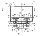
図1から図3は本発明に係る代表的なマイクロ波加熱装置である電子レンジ31の構成図で、図1は正面から見た断面図、図2は図1のA−A‘断面図、図3は図1のB−B‘断面図、図4は、図1のD−D‘断面図である。
(Embodiment 1)
1 to 3 are configuration diagrams of a
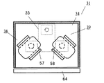
図1に示すように、電子レンジ31は、代表的なマイクロ波発生手段であるマグネトロン32から放射されたマイクロ波を伝送する導波管33と、導波管33の上部に接続され幅方向寸法(約410mm)が奥行き方向寸法(約315mm)より大きい形状の加熱室34と、代表的な被加熱物である食品(図示せず)を載置するため加熱室34内に固定され、セラミックやガラスなどの低損失誘電材料からなるためにマイクロ波が容易に透過できる性質の載置台35と、加熱室34内の載置台35より下方に形成されるアンテナ空間37と、導波管33内のマイクロ波を加熱室34内に放射するため、導波管33からアンテナ空間37にわたり、加熱室34の幅方向に対して対称位置に取り付けられた二つの回転アンテナ38、39と、回転アンテナ38、39を回転駆動できる代表的な駆動手段としてのモータ40、41と、モータ40、41を制御して回転アンテナ38、39の向きを制御する制御手段411と、各回転アンテナ38、39の回転の原点を検出する原点検出機構を構成するフォトインタラプタ36と、加熱室34内の温度分布を検出する温度分布検出手段である赤外線センサ10とを有する。
As shown in FIG. 1, a
また、電子レンジ31は、図2に示すようにドア64を備えている。そして、設定手段63がドア64の下部に配置されている。設定手段63は、使用者が、食品や調理内容に応じて様々な調理メニューを選択できるものである。この選択結果に基づき、制御手段411はマグネトロン32やモータ40、41を制御することができる。
The
回転アンテナ38、39は、放射指向性を有する構成である。本実施の形態1の電子レンジ31は、回転アンテナ38、39のうちの少なくとも一方の放射指向性の強い部位を所定の向きに制御して特定の食品を集中加熱する構成としている。具体的にどのように制御しているかについては後述する。
The rotating
また、回転アンテナ38、39は、導波管33と加熱室底面42との境界面に設けられた直径約30mmで略円形の結合孔43、44を貫通する直径約18mmで略円筒状の導電性材料から成る結合部45、46と、結合部45、46の上端にかしめや溶接などで電気的に接続されて一体化され、概ね垂直方向よりも水平方向に広い面積を有する導電性材料から成る放射部47、48とを備える。
The rotating
また、回転アンテナ38,39は、結合部43、44の中心が回転駆動の中心となるようにモータ40、41のシャフト49、50に嵌合された構成としている。放射部47、48は回転の方向に対して形状が一定ではないために放射指向性がある構成としている。
The rotating
回転アンテナ38、39の回転の中心は加熱室34内の中心から略等距離に配置する。この構成により、アンテナが一つの構成では通常は加熱しにくい加熱室内の中央付近を、回転アンテナ38、39の放射指向性の強い部分を中央付近に向けることにより加熱可能とするものである。
The centers of rotation of the rotating
導波管33は、図3のように上から見てT字型を成し、左右対称な形状であるため、マグネトロン32から結合部45、46までの距離が等しく、かつ結合部45、46は加熱室34の幅方向に対しても対称位置に取り付けられているので、マグネトロン32から放射されるマイクロ波は導波管33、回転アンテナ38、39を介して加熱室34内にほぼ均等に分配される。
Since the
放射部47、48は同一の形状で、放射部上面51、52が略四辺形にRを有する形状で、そのうち対向する2辺には加熱室底面42側に曲げられた放射部曲げ部53、54を有し、その2辺の外側へのマイクロ波の放射を制限する構成である。加熱室底面42と放射部上面51、52までの距離は約10mm程度とし、放射部曲げ部53、54は、それよりも約5mm程度低い位置に引き下げられている。
The radiating
そして,残る2辺は結合部45、46から端部までの水平方向の長さが異なり、結合部の中心からの長さが75mm程度の端部55、56、結合部の中心からの長さが55mm程度の端部57、58を構成している。また端部の幅方向の寸法はいずれも80mm以上としている。この構成において回転アンテナ38、39は、結合部45、46から端部57、58の方向への放射指向性を強くすることができる。
The remaining two sides have different horizontal lengths from the
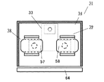
この構成において一般的な食品を均一に加熱する場合は、従来の電子レンジと同様、特に置き場所にこだわる必要はなく、回転アンテナ38、39も従来同様に一定回転させてよい。一方、集中加熱する場合は、加熱室34内の中央付近を加熱する場合、制御手段411は、図4に示すように、回転アンテナ38、39の端部57、58を、加熱室34の幅方向の略中央かつ奥行き方向の略中央という所定の向きに向けるように制御する。
In the case of heating a general food uniformly in this configuration, it is not necessary to pay particular attention to the place of placement as in the case of a conventional microwave oven, and the
回転アンテナ38、39の端部57、58が加熱室34の幅方向の略中央かつ奥行き方向の略中央を向くとき、端部57、58の方向への放射指向性が強いので、特に端部57、58の方向からマイクロ波が放射されその方向に位置する食品を集中的に加熱することができる。
When the
また、加熱室34内の左側付近を加熱する場合、制御手段411は、図5に示すように、回転アンテナ38、39の端部57、58を、左向き(加熱室34をドア64側から見て左側)に向けるように制御する。
Further, when heating the vicinity of the left side in the
回転アンテナ38、39の端部57、58が、両方とも、加熱室34をドア64側から見て左側を向くとき、各アンテナは端部57、58の方向への放射指向性が強いので、特に端部57、58の方向からマイクロ波が放射されその方向に位置する食品を集中的に加熱することができる。
When the
同様に、加熱室34内の右側付近を加熱する場合、制御手段411は、図6に示すように、回転アンテナ38、39の端部57、58を、右向き(加熱室34をドア64側から見て右側)に向けるように制御する。
Similarly, when the vicinity of the right side in the
回転アンテナ38、39の端部57、58が両方とも、加熱室34をドア64側から見て右側を向くとき、各アンテナは端部57、58の方向への放射指向性が強いので、特に端部57、58の方向からマイクロ波が放射されその方向に位置する食品を集中的に加熱することができる。
When both ends 57 and 58 of the
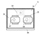
また、加熱室34内の前方中央付近を加熱する場合、制御手段411は、図7に示すように、回転アンテナ38、39の端部57、58を、加熱室34の幅方向の略中央かつ奥行き方向の前方(加熱室34内の中央前方付近)に向けるように制御する。
In addition, when the vicinity of the front center in the
図7に示すように、回転アンテナ38、39の端部57、58が、加熱室34内の中央前方付近を向くとき、各アンテナは端部57、58の方向への放射指向性が強いので、特に端部57、58の方向からマイクロ波が放射されその方向に位置する食品を集中的に加熱することができる。
As shown in FIG. 7, when the
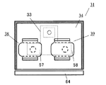
また、加熱室34内の後方中央付近を加熱する場合、制御手段411は、図8に示すように、回転アンテナ38、39の端部57、58を、加熱室34の幅方向の略中央かつ奥行き方向の後方(加熱室34内の中央後方付近)に向けるように制御する。
In addition, when the vicinity of the rear center in the
図8に示すように、回転アンテナ38、39の端部57、58が、加熱室34内の中央後方付近を向くとき、各アンテナは端部57、58の方向への放射指向性が強いので、特に端部57、58の方向からマイクロ波が放射されその方向に位置する食品を集中的に加熱することができる。
As shown in FIG. 8, when the
以上のように、本実施の形態1の電子レンジ31は、局所的に加熱したい場所に応じて回転アンテナの向きを制御するものであり。回転アンテナ38、39を所定の向きに向けるためには、モータ40、41としてステッピングモータを用いるとか、あるいは一定回転のモータであっても基準位置を検出して通電時間を制御するなどの手段が考えられる。
As described above, the
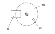
本実施の形態1の電子レンジ31では、モータ40、41としてステッピングモータを用いており、各モータのシャフト40、41にそれぞれ原点検出機構を設けている。この原点検出機構は、図9に示すように、シャフトを中心軸とする円板36aと、フォトインタラプタ36とにより構成される。円板36aには、矩形状のスリット36bが設けられている。
In the
円板36aは、回転アンテナ38、39を回転させるモータのシャフト49、50の軸にそれぞれ共通に取り付けられていて、発光素子と受光素子とを備えたフォトインタラプタ36の光路を遮るように回転するものである。
The
この構成により、スリット36bがフォトインタラプタ36の光路を通過するときは、前記光路を遮るものが無いので、スリットの通過時点を検出することができる。従って、スリット36bの位置を回転アンテナ38、39の原点と設定しておくことで、各モータに取り付けられたフォトインタラプタ36により回転アンテナの原点を検出することができるものである。
With this configuration, when the
また、制御手段411は、原点検出機構で検出できる原点を基準として、回転アンテナ38、39の指向性の強い部分を局所加熱箇所に集中させるときの回転アンテナ38、39の角度(停止位置)を予め記憶しているアンテナ角度記憶部を有している。回転アンテナ38、39の動作を制御して局所加熱を実行する際には、アンテナ角度記憶部の情報が参照される。
Further, the control means 411 uses the origin that can be detected by the origin detection mechanism as a reference, and determines the angle (stop position) of the
なお、ここまで、回転アンテナが二つの場合について説明してきたが、回転アンテナの数はこれに限られず二個以上の複数個でも良く、例えば、図10に示すように、三つの回転アンテナを有する構成としても良い。図10に示す状態では、各回転アンテナの端部が、加熱室内の中央付近を向いており、その中央付近に位置する食品を集中的に加熱することができる。 In addition, although the case where there are two rotating antennas has been described so far, the number of rotating antennas is not limited to this, and may be two or more. For example, as illustrated in FIG. It is good also as a structure. In the state shown in FIG. 10, the end portions of the respective rotating antennas face the vicinity of the center in the heating chamber, and the food located near the center can be intensively heated.
次に、図11を参照して、本実施の形態1の電子レンジ31が備える温度検出手段について説明する。この温度検出手段は、基板19上に一列に並んで設けられた複数の赤外線検出素子13と、基板19全体を収納するケース18と、ケース18を赤外線検出素子13が並んでいる方向と垂直に交わる方向に移動させるステッピングモータ11と、を備えるものである。
Next, with reference to FIG. 11, the temperature detection means with which the
基板19上には、赤外線検出素子13を封入する金属製のカン15と、赤外線検出素子の動作を処理する電子回路20とが設けられている。また、カン15には赤外線が通過するレンズ14が設けられている。また、ケース18には、赤外線を通過させる赤外線通過孔16と、電子回路20からのリード線を通過させる孔17とが設けられている。
On the
この構成により、ステッピングモータ11が回転運動することで、ケース18を、赤外線検出素子13が一列に並んでいる方向とは垂直方向に移動させることができる。
With this configuration, when the stepping
図12は、図1中のC−C‘断面における赤外線温度検出スポットを説明する図である。図に示すように、本実施の形態1の電子レンジ31は、温度検出手段のステッピングモータ11が往復回転動作することにより、加熱室34内のほぼ全ての領域の温度分布を検出することができるものである。
FIG. 12 is a diagram illustrating an infrared temperature detection spot in the C-C ′ cross section in FIG. 1. As shown in the figure, the
具体的には、例えば、まず図12中のA1〜A4の領域の温度分布を、温度検出手段が有する一列に並んだ温度検出素子13(例えば、赤外線センサ)が同時に検出する。次に、ステッピングモータ11が回転動作しケース18が移動するとき、温度検出素子13がB1〜B4の領域の温度分布を検出する。さらに、ステッピングモータ11が回転動作してケース18が移動するとき、温度検出素子13がC1〜C4の領域の温度分布を検出し、同様に、D1〜D4の領域の温度分布が検出される。
Specifically, for example, first, the temperature detection elements 13 (for example, infrared sensors) arranged in a line of the temperature detection means simultaneously detect the temperature distribution in the areas A1 to A4 in FIG. Next, when the stepping
また、上述の動作に続けて、ステッピングモータ11が逆回転することで、D1〜D4の領域側から、C1〜C4、B1〜B4、A1〜A4の順に、温度分布を検出する。温度検出手段は、以上の動作を繰り返すことで、加熱室34内の全体の温度分布を検出することができる。
In addition, the temperature distribution is detected in the order of C1 to C4, B1 to B4, and A1 to A4 from the region side of D1 to D4 by the reverse rotation of the stepping
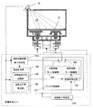
次に、図13を参照して、制御手段411の概略構成を説明する。制御手段411は、回転アンテナ38、39の動作を制御するアンテナ制御部101と、加熱室34内に載置された被加熱物が食品であるか否かを判定する食品判定部102と、加熱処理のうち初期段階の終了を判定する加熱初期段階終了判定部103と、加熱処理全体の終了を判定する加熱終了判定部104とを有する構成である。
Next, a schematic configuration of the
食品判定部102は、被加熱物の初期温度分布を記憶する初期温度分布記憶部108と、被加熱物の単位時間あたりの温度上昇率を算出する温度上昇率算出部109と、を有し、算出した温度上昇率が所定以上の場合に、被加熱物が食品であると判定するものである。これは、すなわち、温度を検出した領域が、被加熱物を載せる載置台であるのか又は加熱対象である食品であるのかを判定するものである。これは載置台はマイクロ波を透過してほとんど温度上昇しないが、食品はマイクロ波を吸収して温度上昇しやすい、その特性の違いにより判別するものである。
The
加熱初期段階終了判定部103は、例えば、加熱開始から所定時間が経過した場合に加熱初期段階が終了したと判定する判定条件や、被加熱物の最高温度が所定温度以上に到達した場合に加熱初期段階が終了したと判定する判定条件や、また、加熱開始から被加熱物の温度変化の最高値が所定以上である場合に加熱初期段階が終了したと判定する判定条件を用いて、加熱処理の初期段階が終了したことを判定するものである。
The heating initial stage
加熱終了判定部104は、例えば、被加熱物の温度分布のうち最高温度が予め設定された設定温度を超えるときに加熱処理を終了すると判定する判定条件や、食品と判定した箇所の平均温度が設定温度を越えるときに加熱処理を終了する判定条件や、また、被加熱物の最高温度が所定温度に到達するのに要する時間を測定し、その要した時間の一定の割合(例えば、50%)を追加加熱時間として加熱処理し、その後追加加熱時間が終了したときに加熱処理を終了する構成等により、加熱処理の終了を判定するものである。
The heating
アンテナ制御部101は、加熱室内を均一加熱させるべく回転アンテナ38、39の動作を制御する分散加熱モード制御部105と、被加熱物の低温部分を加熱すべく回転アンテナ38、39の動作を制御する局所加熱(スポット加熱)モード制御部106と、加熱室内に載置された被加熱物の低温部を検出する低温部抽出部107とを有する構成である。
The antenna control unit 101 controls the operation of the
分散加熱モード制御部105は、例えば、マイクロ波発振中に所定の位置で停止させることで局所的な加熱のできる二つの回転アンテナ38、39を、その停止位置を刻々と変化させることで分散加熱を実現したり、回転アンテナ38、39を連続的に回転させることで分散加熱を実現したり、また、回転アンテナ38、39の停止位置をランダムに変えることで分散加熱を実現する構成である。
For example, the distributed heating
局所加熱モード制御部106は、低温部抽出部107より最低温度箇所の情報を得て、局所加熱すべく回転アンテナ38、39の向きを制御する構成である。例えば、最低温度箇所が、図12中のB2、B3、C2、C3のいずれかであれば、回転アンテナ38、39が中央を加熱する向き、すなわち図4に示した停止位置に回転アンテナ38、39を停止させる。
The local heating
また、最低温度箇所が、図12中のB1、C1のいずれかであれば、回転アンテナ38,39が左方向を加熱する向き、すなわち図5に示した停止位置に回転アンテナ38、39を停止させる。また、最低温度箇所が、図12中のB4、C4のいずれかであれば、回転アンテナ38,39が右方向を加熱する向き、すなわち図6に示した停止位置に回転アンテナ38、39を停止させる。
If the lowest temperature point is either B1 or C1 in FIG. 12, the rotating
また、最低温度箇所が、図12中のA2、A3のいずれかであれば、回転アンテナ38,39が前方を加熱する向き、すなわち図7に示した停止位置に回転アンテナ38、39を停止させる。また、最低温度箇所が、図12中のD2、D3のいずれかであれば、回転アンテナ38,39が後方を加熱する向き、すなわち図8に示した向きに回転アンテナ38、39を停止させる。
Also, if the lowest temperature location is one of A2 and A3 in FIG. 12, the rotating
以上のように、制御手段411は、温度検出手段が検出した最低温度箇所に応じて、回転アンテナ38、39の停止位置を制御するものであるが、このとき、回転アンテナが所定の位置に停止したまま加熱室内にマイクロ波を放射しつづけると、回転アンテナ自体が昇温し過ぎて融解する恐れがある。
As described above, the
この点を鑑みて、制御手段411の局所加熱モード制御部106は、上述の局所加熱モード時に、回転アンテナを目標角度(停止位置)を中心として所定角度(例えば、±5度)程度往復揺動させるものである。これにより、局所的加熱効果に影響を与えることなく回転アンテナの劣化を防止することができる。また、マイクロ波放射中に回転アンテナが停止しつづけることで、回転アンテナの一部にマイクロ波が集中しすぎて、過剰加熱することを防止する。この往復揺動動作は、局所加熱開始時から行っても良いが、局所加熱開始時から所定時間経過後(例えば、30秒〜1分後)に開始する構成としてもよい。
In view of this point, the local heating
この往復揺動動作を実行するために、制御手段411は、回転アンテナ38、39が停止することを許容する上限時間を予め記憶する停止上限時間記憶部と、回転アンテナが停止している時間をカウントする停止時間計時部と、回転アンテナ38、39を往復揺動させる角度を記憶する往復角度記憶部と、を有している。
In order to execute this reciprocating rocking motion, the control means 411 includes a stop upper limit time storage unit that stores in advance an upper limit time that allows the
また、局所加熱開始時から所定時間経過後(例えば、30秒〜1分後)に回転アンテナを所定角度(例えば、5度)だけ回転させる構成としても良い。 Moreover, it is good also as a structure which rotates a rotation antenna only a predetermined angle (for example, 5 degree | times) after predetermined time progress (for example, 30 second-after 1 minute) from the time of a local heating start.
また、制御手段411は、回転アンテナ38、39が所定の停止位置(角度)にあるときを原点として記憶している。そして、制御手段411は、例えば、加熱処理実行前または加熱処理実行後に回転アンテナ38、39の原点を確認する原点検出モードを実行する。
Further, the control means 411 stores the time when the
原点検出モード中は、回転アンテナ38、39の角度を特定することができず、このままマイクロ波を発振すると不本意な加熱状態を起こし不良の原因となってしまうことがある。そこで、制御手段411は、原点検出モード中で回転アンテナを駆動している間は、マグネトロンの動作を停止する制御を行う。
During the origin detection mode, the angles of the
また、制御手段411は、原点検出モードを加熱処理終了後に行い、原点を検出した状態で非加熱時に待機する。これにより、加熱処理を開始する前に原点検出のための待機時間が発生するのを防ぐことできる。
Further, the
また、制御手段411は、原点検出モードで原点が見つからなかった場合には、エラーと判定してそれ以降の加熱処理の実行を禁止するメニューと、回転アンテナ38,39を停止させた状態で加熱処理を実行するメニューと、を有するものである。この構成により、調理メニューに応じて、例えば、加熱室34内の温度分布の偏っていても構わないメニュー(単に加熱処理できればムラがあっても良い場合等)のときは、回転アンテナ38、39の動作を停止したまま加熱処理を実行するので、ユーザに対して最低限の機能を提供することができる。
In addition, when the origin is not found in the origin detection mode, the
なお、原点が検出できない場合は、回転アンテナ38、39を駆動するモータ40、41が故障している場合もあり、その状態のまま回転アンテナ38、39を動作させることは危険であるので、回転アンテナ38、39の動作は停止させるものである。
If the origin cannot be detected, the
一方、加熱室34内の温度分布が偏っていたのではユーザが所望する出来栄えの加熱処理を実現することができないメニューのときは、加熱処理の実行自体を禁止するものである。
On the other hand, if the temperature distribution in the
また、制御手段411は、加熱開始の初期段階においては分散加熱モードで加熱室34全体を均一加熱し、加熱室34内の温度分布に差が生じはじめたときに局所加熱モードに移行するものとしても良い。加熱開始の初期段階では加熱室34内の温度分布に差がないので、分散加熱モードが効率よく加熱室34全体を昇温させることができる。
In addition, the control means 411 uniformly heats the
また、制御手段411は、加熱開始の初期段階においては、まず、加熱室34内の中央付近を局所的に加熱するものとしても良い。通常、加熱室内の温度分布に差がない状態から加熱処理を開始すると、加熱室の中央付近が最も昇温しにくい。従って、まず、加熱室34内の中央付近を局所加熱し、その後、分散加熱を行って加熱室全体の均一加熱を行うことで、効率よく加熱室全体を均一加熱することができる。
Further, in the initial stage of starting heating, the
また、各回転アンテナ38、39を駆動するモータ40、41は、例えば、ステッピングモータとしても良い。このとき、制御手段411は、各回転アンテナ38、39に取り付けられた各ステッピングモータに対してパルスを入力するタイミングを、各ステッピングモータ毎に時間差を設けて同時にならないように制御すると良い。同時にパルスを入力すると、そのタイミングで必要な電流が増大し、電子レンジ31に大電流に対応可能な回路を設置しなければならなくなるが、時間差を設けてパルスを入力することで回路が大型化するのを防止できる。
In addition, the
次に、本実施の形態1の電子レンジ31の動作について説明する。まず、加熱初期段階時の動作について、図14を参照して説明する。
Next, the operation of the
まず、加熱処理が開始されると、マグネトロン32がマイクロ波を発生させ、そのマイクロ波が導波菅を介して加熱室34内に伝送される(S101)。このとき、温度検出手段は、加熱初期時点での加熱室34内の温度分布を検出し、制御手段411は温度分布の検出結果を記憶する(S102)。
First, when the heat treatment is started, the
次に、制御手段411は、分散加熱を実現するために、例えば、回転アンテナ38、39を一定速度で回転させる(S103)。一定時間経過後、温度検出手段は、再び加熱室34内の温度分布を検出する(S104)。
Next, the control means 411 rotates, for example, the rotating
そして、制御手段411の加熱初期段階終了判定部103は、S102の段階で検出した加熱初期段階での加熱室内の温度分布と、S104の段階で検出した一定時間経過後の加熱室内の温度分布とを参照して、一定の加熱初期段階終了の判定条件が見たされているか否かを判断する。判定条件が具備されていなかった場合は(S105−No)、続けて加熱室34内を分散加熱し、所定時間経過後に再び加熱室34内の温度分布を検出する。
And the heating initial stage completion | finish
判定条件が具備されていた場合は(S105−Yes)、温度検出手段が温度を検出した各領域が、食品が載置された領域であるか否かを判定するステップに移行する。このステップでは、例えば、温度を検出した各領域の単位時間あたりの温度上昇率を参照し、所定値以上である場合には、その領域に食品が載置されていると判断する。また、温度を検出した各領域について初期温度を参照し、その初期温度がマイナスだった場合(例えば、冷凍食品等が想定される)に、その領域は食品が載置されている領域と判断しても良い。このように、S106のステップにおいては、加熱室34内の全領域のうち、食品が載置されている領域と、食品が載置されていないその他の領域とを判別し、制御手段411に記憶しておく。(S106)。
If the determination condition is satisfied (S105-Yes), the process proceeds to a step of determining whether or not each area where the temperature detecting means detects the temperature is an area where food is placed. In this step, for example, the temperature increase rate per unit time of each area where the temperature is detected is referred to, and if it is equal to or greater than a predetermined value, it is determined that food is placed in that area. In addition, referring to the initial temperature for each area where the temperature is detected, if the initial temperature is negative (for example, frozen food is assumed), the area is determined to be an area where food is placed. May be. As described above, in the step of S106, among all the regions in the
加熱初期段階が終了すると、電子レンジ31は、続けて、加熱フィードバック段階へ移行する。図15を参照して、加熱フィードバック段階の動作について説明する。電子レンジ31の温度分布検出手段は、加熱初期段階が終了した後、加熱室34内の全体の温度分布を検出する(S107)。そして、加熱室34内で食品が載置されていると判定されている領域内での最低温度の領域を抽出、すなわち、食品箇所のうち最低温度箇所を抽出する(S108)。
When the initial heating stage ends, the
その最低温度箇所が図12中のB2、B3、C2、C3のいずれかの領域であるか否かを判定する(S109)。最低温度箇所がB2、B3、C2、C3のいずれかの領域であった場合は(S109−Yes)、制御手段411は、回転アンテナ38、39が加熱3室34内の中央を加熱する向き、すなわち図4に示した停止位置に回転アンテナ38、39を停止させるように動作制御を実行する(S117)。
It is determined whether or not the minimum temperature location is any one of B2, B3, C2, and C3 in FIG. 12 (S109). When the lowest temperature portion is any one of B2, B3, C2, and C3 (S109-Yes), the control means 411 causes the
最低温度箇所がB2、B3、C2、C3のいずれの領域でもなかった場合は(S109−No)、続けて、食品箇所のうち最低温度箇所がB1、C1のいずれかである否かを判定する(S110)。 When the lowest temperature location is not any of B2, B3, C2, and C3 (S109-No), it is determined whether the lowest temperature location is any of B1 and C1 among the food locations. (S110).
最低温度箇所がB1、C1、のいずれかの領域であった場合は(S110−Yes)、制御手段411は、回転アンテナ38、39が加熱室34内の左方向を加熱する向き、すなわち図5に示した停止位置に回転アンテナ38、39を停止させるように動作制御を実行する(S118)。
When the lowest temperature location is any one of B1 and C1 (S110-Yes), the control means 411 directs the
最低温度箇所がB1、C1のいずれの領域でもなかった場合は(S110−No)、続けて、食品箇所のうち最低温度箇所がB4、C4のいずれかである否かを判定する(S111)。 If the lowest temperature location is neither B1 nor C1 (S110-No), it is then determined whether the lowest temperature location is B4 or C4 among the food locations (S111).
最低温度箇所がB4、C4、のいずれかの領域であった場合は(S111−Yes)、制御手段411は、回転アンテナ38、39が加熱室34内の右方向を加熱する向き、すなわち図6に示した停止位置に回転アンテナ38、39を停止させるように動作制御を実行する(S119)。
When the lowest temperature location is any region of B4 and C4 (S111-Yes), the control means 411 causes the
最低温度箇所がB4、C4のいずれの領域でもなかった場合は(S111−No)、続けて、食品箇所のうち最低温度箇所がA2、A3のいずれかである否かを判定する(S112)。 If the lowest temperature location is neither B4 nor C4 (S111-No), it is subsequently determined whether the lowest temperature location of the food location is A2 or A3 (S112).
最低温度箇所がA2、A3、のいずれかの領域であった場合は(S112−Yes)、制御手段411は、回転アンテナ38、39が加熱室34内の前方向を加熱する向き、すなわち図7に示した停止位置に回転アンテナ38、39を停止させるように動作制御を実行する(S120)。
When the lowest temperature location is one of the areas A2 and A3 (S112-Yes), the control means 411 directs the
最低温度箇所がA2、A3のいずれの領域でもなかった場合は(S112−No)、続けて、食品箇所のうち最低温度箇所がD2、D3のいずれかであるか否かを判定する(S113)。 When the lowest temperature location is not in any of the areas A2 and A3 (S112-No), it is subsequently determined whether the lowest temperature location of the food location is either D2 or D3 (S113). .
最低温度箇所がD2、D3、のいずれかの領域であった場合は(S113−Yes)、制御手段411は、回転アンテナ38、39が加熱室34内の後方向を加熱する向き、すなわち図8に示した停止位置に回転アンテナ38、39を停止させるように動作制御を実行する(S121)。
When the lowest temperature location is one of D2 and D3 (S113-Yes), the control means 411 directs the
最低温度箇所がD2、D3のいずれの領域でもなかった場合は(S113−No)、続けて、制御手段411は、回転アンテナ38、39を一定回転させて加熱室34内を均一加熱する分散加熱モードに移行する(S114)。
If the lowest temperature location is neither D2 nor D3 (S113-No), then the control means 411 performs distributed heating in which the inside of the
制御手段411は、S114、S117〜S121のいずれかステップを実行した後に、終了判定を行う(S115)。例えば、食品の温度分布のうち最高温度が予め設定された設定温度を超えるときに加熱処理を終了すると判定する加熱処理終了判定条件や、食品と判定した箇所の平均温度が設定温度を越えるときに加熱処理を終了すると判定する加熱処理終了判定条件を満たしているか否かを判定する。 The control means 411 performs an end determination after executing any one of steps S114 and S117 to S121 (S115). For example, when the maximum temperature of the food temperature distribution exceeds a preset temperature, the heat treatment end determination condition for determining that the heat treatment is to be terminated, or when the average temperature of the location determined as food exceeds the set temperature It is determined whether or not a heat treatment end determination condition for determining to end the heat treatment is satisfied.
加熱処理終了判定条件を満たしていた場合は(S115−Yes)、加熱処理を終了する(S116)。加熱処理終了判定条件を満たしていない場合は(S115−No)、S107のステップの段階に移行し、再びS107以降のステップを繰り返す。 When the heat treatment end determination condition is satisfied (S115-Yes), the heat treatment is ended (S116). When the heat treatment end determination condition is not satisfied (S115-No), the process proceeds to the step of S107, and the steps after S107 are repeated again.
以上のように、本実施の形態1の電子レンジ31は、二つの回転アンテナにより加熱室34内の特定の箇所を集中的に加熱することができるものであり、加熱処理中に被加熱物である食品の温度分布を検出し、その食品の最低温度箇所にスポットを当てて局所的に加熱することができるので、食品をムラなく加熱処理することができる。
As described above, the
また、局所的加熱と分散加熱とを食品の温度分布に応じて切り換えることができ、すなわち必要な箇所にマイクロ波を集中させることができるので、効率よく短時間で食品を加熱することができる。 In addition, the local heating and the dispersion heating can be switched according to the temperature distribution of the food, that is, the microwave can be concentrated at a necessary place, so that the food can be efficiently heated in a short time.
なお、図15において説明した加熱フィードバック段階の動作制御については、食品の最低温度箇所を探索する順序はこれに限られず、結果として食品全体を探索するものであれば他の順序で実行しても良い。 Note that the operation control in the heating feedback stage described in FIG. 15 is not limited to the order of searching for the minimum temperature portion of the food, and may be executed in another order as long as the entire food is searched as a result. good.
(実施の形態2)
図16は、本実施の形態2の電子レンジの加熱フィードバック段階を説明するフローチャートである。なお、以下の説明では、上述した構成要素と同一の構成要素には同一の符号を付し、その説明を省略する。
(Embodiment 2)
FIG. 16 is a flowchart illustrating the heating feedback stage of the microwave oven according to the second embodiment. In the following description, the same components as those described above are denoted by the same reference numerals, and the description thereof is omitted.
本実施の形態2の電子レンジ31は、加熱初期段階が終了した後、図16に示す加熱フィードバック段階に移行する。図15に示した実施の形態1の加熱フィードバック制御と図16に示した本実施の形態2の加熱フィードバック制御との違いは、本実施の形態2の加熱フィードバック制御が、加熱室34内の各領域(A1〜A4、B1〜B4、C1〜C4、D1〜D4)を、中央領域A(B2、B3、C2、C3)と左側領域B(B1、C1)と右側領域C(B4、C4)と前方領域D(A2、A3)と後方領域E(D2、D3)とに分類し、その分類した領域内の食品箇所の平均温度に基づいて加熱フィードバックを行う点にある。
In the
図16を参照して、本実施の形態2の加熱フィードバック段階の動作制御について説明する。電子レンジ31の温度検出手段は、加熱初期段階が終了した後、加熱室34内の全体の温度分布を検出する(S201)。そして、中央領域A(B2、B3、C2、C3)と左側領域B(B1、C1)と右側領域C(B4、C4)と前方領域D(A2、A3)と後方領域E(D2、D3)毎に食品箇所の平均温度を算出する(S202)。
With reference to FIG. 16, the operation control in the heating feedback stage of the second embodiment will be described. The temperature detection means of the
続けて、分類した各領域(A〜F)のうち平均温度が最低である領域を求め、その結果に応じて回転アンテナ38、39の動作を制御する。まず、分類した各領域(A〜F)のうち最低温度領域(平均温度が最低である領域)が中央領域Aであるか否かを判定する。最低温度領域が中央領域Aであった場合(S203−Yes)、制御手段411は、回転アンテナ38、39が加熱室34内の中央を加熱する向き、すなわち図4に示した停止位置に回転アンテナ38、39を停止させるように動作制御を実行する(S210)。
Subsequently, an area having the lowest average temperature is obtained from the classified areas (A to F), and the operations of the
最低温度領域が中央領域Aでなかった場合は(S203−No)、続けて、分類した各領域(A〜F)のうち最低温度領域が左側領域Bであるか否かを判定する(S204)。
最低温度領域が左側領域Bであった場合(S204−Yes)、制御手段411は、回転アンテナ38、39が加熱室34内の左側を加熱する向き、すなわち図5に示した停止位置に回転アンテナ38、39を停止させるように動作制御を実行する(S211)。
When the lowest temperature region is not the central region A (S203-No), it is determined whether the lowest temperature region is the left region B among the classified regions (A to F) (S204). .
When the lowest temperature region is the left region B (S204-Yes), the
最低温度領域が左側領域Bでなかった場合は(S204−No)、続けて、分類した各領域(A〜F)のうち最低温度領域が右側領域Cであるか否かを判定する(S205)。
最低温度領域が右側領域Cであった場合(S205−Yes)、制御手段411は、回転アンテナ38、39が加熱室34内の右側を加熱する向き、すなわち図6に示した停止位置に回転アンテナ38、39を停止させるように動作制御を実行する(S212)。
When the lowest temperature region is not the left region B (S204-No), it is determined whether the lowest temperature region is the right region C among the classified regions (A to F) (S205). .
When the lowest temperature region is the right region C (S205-Yes), the control means 411 determines that the
最低温度領域が右側領域Cでなかった場合は(S205−No)、続けて、分類した各領域(A〜F)のうち最低温度領域が前方領域Dであるか否かを判定する(S206)。
最低温度領域が前方領域Dであった場合(S206−Yes)、制御手段411は、回転アンテナ38、39が加熱室34内の前方側を加熱する向き、すなわち図7に示した停止位置に回転アンテナ38、39を停止させるように動作制御を実行する(S213)。
When the lowest temperature region is not the right region C (S205-No), it is determined whether the lowest temperature region is the front region D among the classified regions (A to F) (S206). .
When the lowest temperature region is the front region D (S206-Yes), the
最低温度領域が前方領域Dでなかった場合は(S206−No)、続けて、分類した各領域(A〜F)のうち最低温度領域が後方領域Eであるか否かを判定する(S207)。
最低温度領域が後方領域Eであった場合(S207−Yes)、制御手段411は、回転アンテナ38、39が加熱室34内の後方側を加熱する向き、すなわち図8に示した停止位置に回転アンテナ38、39を停止させるように動作制御を実行する(S214)。
When the lowest temperature region is not the front region D (S206-No), it is determined whether the lowest temperature region is the rear region E among the classified regions (A to F) (S207). .
When the lowest temperature region is the rear region E (S207-Yes), the
最低温度箇所が後方領域Eでもなかった場合は(S207−No)、続けて、制御手段411は、回転アンテナ38、39を一定回転させて加熱室34内を均一加熱する分散加熱モードに移行する(S208)。
If the lowest temperature location is not the rear region E (S207-No), then the
制御手段は、S208、S210〜S214のいずれかステップを実行した後に、終了判定を行う(S209)。実施の形態1と同様に、例えば、食品の温度分布のうち最高温度が、予め設定された設定温度を超えるときに加熱処理を終了すると判定したり、食品と判定した箇所の平均温度が設定温度を越えるときに加熱処理を終了すると判定する加熱処理終了判定条件を満たしているか否かを判定する。 The control means performs an end determination after executing any one of steps S208 and S210 to S214 (S209). As in the first embodiment, for example, it is determined that the heating process is terminated when the maximum temperature of the temperature distribution of the food exceeds a preset temperature, or the average temperature at the location determined as the food is the set temperature. It is determined whether or not a heat treatment end determination condition for determining that the heat treatment is to be ended when the temperature exceeds is satisfied.
加熱処理終了判定条件を満たしていた場合は(S209−Yes)、加熱処理を終了する(S116)。加熱処理終了判定条件を満たしていない場合は(S209−No)、S201のステップの段階に移行し、再びS201以降のステップを繰り返す。 If the heat treatment end determination condition is satisfied (S209—Yes), the heat treatment is terminated (S116). When the heat treatment end determination condition is not satisfied (S209-No), the process proceeds to the step of S201, and the steps after S201 are repeated again.
このように、本実施の形態2の電子レンジ31は、分類した一定領域内(A〜E)の食品箇所の平均温度に基づいて、局所加熱箇所を決定するので、食品の一箇所だけが極端に低い場合であっても、食品全体として加熱が必要な箇所に対して集中加熱を行うことができる。
Thus, since the
(実施の形態3)
本実施の形態3の電子レンジとして、回転アンテナの変形例について説明する。なお、以下の説明では、上述した構成要素と同一の構成要素には同一の符号を付し、その説明を省略する。例えば、回転アンテナとしては、図17に示すように、円板形状の一部に開口部を有するものであっても良い。
(Embodiment 3)
A modification of the rotating antenna will be described as the microwave oven according to the third embodiment. In the following description, the same components as those described above are denoted by the same reference numerals, and the description thereof is omitted. For example, as shown in FIG. 17, the rotating antenna may have an opening in a part of a disk shape.
具体的には、図17中、回転アンテナ83、84は、放射部85、86上に円弧形状の開口部87、88を有している。この開口部87、88は、幅方向の長さL1が加熱室内に放射されるマイクロ波の波長の4分の1以上としている。従って、回転アンテナ83、84は、停止しているときは開口部に放射指向性がある構成となり、加熱室34内の特定の領域を局所的に加熱することを可能とする。
Specifically, in FIG. 17, the rotating
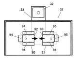
また、回転アンテナの他の変形例としては、例えば、図18に示すように、長方形状の回転アンテナ90、91がある。この回転アンテナ90、91は、長方形状のうち3辺側が加熱室底面側に曲げられた曲げ部94、95を有し、残り1辺部分92,93が折り曲げておらず、その折り曲げられていない辺部分92、93に指向性が強い構成となり、加熱室34内の特定の領域を局所的に加熱することを可能とする。
In addition, as another modification of the rotating antenna, for example, there are rectangular
また、回転アンテナの他の変形例としては、例えば、図19に示すように、長方形状の回転アンテナ201、202がある。回転アンテナ201、202は、長方形状の4辺側に加熱室底面側に曲げられた曲げ部203、204を有し、さらに、放射部206、207上に開口部208、209を有することで指向性が強い構成となり、加熱室34内の特定の領域を局所的に加熱することを可能とする。
Further, as another modification of the rotating antenna, for example, there are rectangular
また、各回転アンテナは、互いの間隔を5[mm]以上空けるものとしている。これにより、各回転アンテナが互いに干渉して回転アンテナの一部等が過剰加熱で破損することを防止することができる。 In addition, the rotating antennas are spaced from each other by 5 [mm] or more. As a result, it is possible to prevent the rotating antennas from interfering with each other to partially damage the rotating antennas due to excessive heating.
なお、以上に示した実施の形態は様々に組み合わせて実施することができるものである。
本発明を詳細にまた特定の実施態様を参照して説明したが、本発明の精神と範囲を逸脱することなく様々な変更や修正を加えることができることは当業者にとって明らかである。
Note that the embodiment described above can be implemented in various combinations.
Although the present invention has been described in detail and with reference to specific embodiments, it will be apparent to those skilled in the art that various changes and modifications can be made without departing from the spirit and scope of the invention.
以上のように、本発明は、加熱室に配置された回転アンテナの放射指向性の強い部位を所定の向きに制御して特定の被加熱物を集中加熱することができるので、食品などの各種誘電体の加熱、解凍、陶芸加熱、乾燥、焼結、或いは生体化学反応等の用途にも適用することができるものである。 As described above, according to the present invention, a specific portion to be heated can be centrally heated by controlling a portion having a strong radiation directivity of a rotating antenna disposed in a heating chamber in a predetermined direction. It can also be applied to uses such as dielectric heating, thawing, ceramics heating, drying, sintering, or biochemical reaction.
10 温度センサ(温度検出手段)
31 電子レンジ(マイクロ波加熱装置 )
32 マグネトロン(マイクロ波発生手段 )
33 導波管
34 加熱室
35 載置台
37 アンテナ空間
38、39、 回転アンテナ
40、41 モータ(駆動手段)
411 制御手段
10 Temperature sensor (temperature detection means)
31 Microwave oven (microwave heating device)
32 Magnetron (microwave generation means)
33
411 Control means
Claims (2)
前記マイクロ波発生手段からマイクロ波を伝送する導波管と、
前記マイクロ波で加熱する被加熱物を収納する加熱室と、
前記導波管から前記加熱室に前記マイクロ波を下方から放射するための複数の回転アンテナと、
前記回転アンテナを回転駆動する駆動手段と、
前記加熱室内の温度分布を検出する温度分布検出手段と、
前記温度分布検出手段の検出結果に基づき前記駆動手段を制御して前記回転アンテナの向きを制御する制御手段とを有し、
前記制御手段は、前記加熱室内の特定の領域に対して前記回転アンテナの放射指向性の強い部分を向けるときの前記回転アンテナの角度を記憶するアンテナ角度記憶部と、前記回転アンテナが所定の角度で停止することを許容する上限時間を記憶する停止上限時間記憶部と、前記回転アンテナが停止している時間をカウントする停止時間計時部とを有し、前記温度分布検出手段が検出した各検出領域の温度のうち低温部分に前記回転アンテナの放射指向性の強い部分を向けて停止し、前記停止時間計時部がカウントした時間が前記停止上限時間記憶部が記憶する時間に到達するとき、所定の角度で停止している前記回転アンテナを所定角度ずらした位置に移動させるマイクロ波加熱装置。 Microwave generation means;
A waveguide for transmitting microwaves from the microwave generating means;
A heating chamber for storing an object to be heated by the microwave;
A plurality of rotating antennas for radiating the microwave from below to the heating chamber from the waveguide;
Drive means for rotationally driving the rotating antenna;
Temperature distribution detecting means for detecting a temperature distribution in the heating chamber;
Control means for controlling the direction of the rotating antenna by controlling the driving means based on the detection result of the temperature distribution detecting means,
The control means includes an antenna angle storage unit that stores an angle of the rotating antenna when a portion having a strong radiation directivity of the rotating antenna is directed to a specific region in the heating chamber, and the rotating antenna has a predetermined angle. Each of the detections detected by the temperature distribution detecting means, including a stop upper limit time storage unit that stores an upper limit time allowed to stop at, and a stop time counting unit that counts a time during which the rotating antenna is stopped. when toward the portion having strong radiation directivity of the rotation antenna in a low temperature portion of the temperature region is stopped, the time the stop time counting unit has counted reaches the time stored is the stop upper limit time storing unit, a predetermined A microwave heating apparatus that moves the rotating antenna, which is stopped at an angle, to a position shifted by a predetermined angle .
Priority Applications (5)
| Application Number | Priority Date | Filing Date | Title |
|---|---|---|---|
| JP2006169268A JP4979280B2 (en) | 2006-06-19 | 2006-06-19 | Microwave heating device |
| EP07745423.9A EP2051563B1 (en) | 2006-06-19 | 2007-06-15 | Microwave heating device |
| US12/305,314 US8525086B2 (en) | 2006-06-19 | 2007-06-15 | Microwave heating appliance |
| CN2007800230730A CN101473692B (en) | 2006-06-19 | 2007-06-15 | Microwave heating device |
| PCT/JP2007/062169 WO2007148632A1 (en) | 2006-06-19 | 2007-06-15 | Microwave heating device |
Applications Claiming Priority (1)
| Application Number | Priority Date | Filing Date | Title |
|---|---|---|---|
| JP2006169268A JP4979280B2 (en) | 2006-06-19 | 2006-06-19 | Microwave heating device |
Publications (3)
| Publication Number | Publication Date |
|---|---|
| JP2007335377A JP2007335377A (en) | 2007-12-27 |
| JP2007335377A5 JP2007335377A5 (en) | 2009-07-30 |
| JP4979280B2 true JP4979280B2 (en) | 2012-07-18 |
Family
ID=38833374
Family Applications (1)
| Application Number | Title | Priority Date | Filing Date |
|---|---|---|---|
| JP2006169268A Expired - Fee Related JP4979280B2 (en) | 2006-06-19 | 2006-06-19 | Microwave heating device |
Country Status (5)
| Country | Link |
|---|---|
| US (1) | US8525086B2 (en) |
| EP (1) | EP2051563B1 (en) |
| JP (1) | JP4979280B2 (en) |
| CN (1) | CN101473692B (en) |
| WO (1) | WO2007148632A1 (en) |
Families Citing this family (55)
| Publication number | Priority date | Publication date | Assignee | Title |
|---|---|---|---|---|
| WO2008108046A1 (en) * | 2007-03-07 | 2008-09-12 | Panasonic Corporation | Microwave heating device |
| JP5273930B2 (en) * | 2007-03-07 | 2013-08-28 | パナソニック株式会社 | Microwave heating device |
| JP5217882B2 (en) * | 2008-10-10 | 2013-06-19 | パナソニック株式会社 | Microwave processing equipment |
| JP5217881B2 (en) * | 2008-10-10 | 2013-06-19 | パナソニック株式会社 | Microwave processing equipment |
| WO2010073528A1 (en) * | 2008-12-25 | 2010-07-01 | パナソニック株式会社 | Microwave cooking device |
| US9215756B2 (en) | 2009-11-10 | 2015-12-15 | Goji Limited | Device and method for controlling energy |
| ES2563734T3 (en) | 2010-05-03 | 2016-03-16 | Goji Limited | Modal analysis |
| PL2393340T3 (en) * | 2010-06-04 | 2015-12-31 | Whirlpool Co | Microwave heating apparatus with rotatable antenna and method thereof |
| JP5820661B2 (en) * | 2010-09-14 | 2015-11-24 | 東京エレクトロン株式会社 | Microwave irradiation device |
| AU2011311838B2 (en) * | 2010-10-07 | 2015-07-30 | Milt D. Mathis | Microwave rotary kiln |
| JP2013053795A (en) * | 2011-09-02 | 2013-03-21 | Toshiba Corp | Heating cooker |
| CN102519057B (en) * | 2011-12-22 | 2015-03-25 | 宁波方太厨具有限公司 | Device for detecting microwave stirring mechanism of flat plate-type microwave oven |
| CN103591620B (en) * | 2012-08-16 | 2017-03-08 | 广东美的厨房电器制造有限公司 | A kind of microwave oven and its control method |
| CN103634959B (en) * | 2012-08-20 | 2015-12-02 | 侯梦斌 | A kind of microwave heating equipment with automatic loading and unloading raw material box alms bowl and technique |
| DE102012222156A1 (en) * | 2012-12-04 | 2014-06-05 | BSH Bosch und Siemens Hausgeräte GmbH | microwave |
| EP3195695A4 (en) * | 2014-09-17 | 2018-05-16 | Whirlpool Corporation | Direct heating through patch antennas |
| CN104235901A (en) * | 2014-09-25 | 2014-12-24 | 广东美的厨房电器制造有限公司 | Microwave oven food thawing control method and microwave oven |
| EP3199873A4 (en) * | 2014-09-25 | 2018-05-16 | Guangdong Midea Kitchen Appliances Manufacturing Co., Ltd. | Microwave oven thawing control method, device, and microwave oven |
| CN104456648B (en) * | 2014-11-24 | 2017-04-05 | 广东美的厨房电器制造有限公司 | Microwave oven |
| US11229095B2 (en) * | 2014-12-17 | 2022-01-18 | Campbell Soup Company | Electromagnetic wave food processing system and methods |
| CN105737540A (en) * | 2016-03-05 | 2016-07-06 | 何朝武 | Intelligent adjusting drying system |
| CN105655724B (en) * | 2016-03-07 | 2018-11-02 | 南京航空航天大学 | Towards the cured microwave antenna array of Composite Microwave |
| CN108781486B (en) * | 2016-03-25 | 2021-08-10 | 松下知识产权经营株式会社 | Microwave heating device |
| US10004115B2 (en) * | 2016-06-13 | 2018-06-19 | The Markov Corporation | Electronic oven with reflective energy steering |
| WO2018004539A1 (en) * | 2016-06-28 | 2018-01-04 | Whirlpool Corporation | Multi-feed microwave oven with improved crisp function |
| US11246191B2 (en) | 2016-09-22 | 2022-02-08 | Whirlpool Corporation | Method and system for radio frequency electromagnetic energy delivery |
| EP3530074A4 (en) | 2016-10-19 | 2020-05-27 | Whirlpool Corporation | Food load cooking time modulation |
| EP3529536B1 (en) | 2016-10-19 | 2021-07-14 | Whirlpool Corporation | System and method for food preparation utilizing a multi-layer model |
| EP3530075A4 (en) | 2016-10-19 | 2020-05-27 | Whirlpool Corporation | Method and device for electromagnetic cooking using closed loop control |
| WO2018118065A1 (en) | 2016-12-22 | 2018-06-28 | Whirlpool Corporation | Method and device for electromagnetic cooking using non-centered loads |
| EP3560291A4 (en) | 2016-12-22 | 2020-11-25 | Whirlpool Corporation | Method and device for electromagnetic cooking using non-centered loads management through spectromodal axis rotation |
| WO2018120773A1 (en) | 2016-12-28 | 2018-07-05 | Guangdong Oppo Mobile Telecommunications Corp., Ltd. | Antenna device for mobile terminal and mobile terminal |
| US11638333B2 (en) | 2016-12-29 | 2023-04-25 | Whirlpool Corporation | System and method for analyzing a frequency response of an electromagnetic cooking device |
| US11343883B2 (en) | 2016-12-29 | 2022-05-24 | Whirlpool Corporation | Detecting changes in food load characteristics using Q-factor |
| US11184960B2 (en) | 2016-12-29 | 2021-11-23 | Whirlpool Corporation | System and method for controlling power for a cooking device |
| US11483906B2 (en) | 2016-12-29 | 2022-10-25 | Whirlpool Corporation | System and method for detecting cooking level of food load |
| CN109792809B (en) | 2016-12-29 | 2021-03-26 | 松下电器产业株式会社 | Electromagnetic cooking apparatus and method of controlling cooking in electromagnetic cooking apparatus |
| EP3563638B1 (en) | 2016-12-29 | 2021-09-01 | Whirlpool Corporation | Electromagnetic cooking device with automatic melt operation and method of controlling cooking in the electromagnetic cooking device |
| US11432379B2 (en) | 2016-12-29 | 2022-08-30 | Whirlpool Corporation | Electromagnetic cooking device with automatic liquid heating and method of controlling cooking in the electromagnetic cooking device |
| US11503679B2 (en) | 2016-12-29 | 2022-11-15 | Whirlpool Corporation | Electromagnetic cooking device with automatic popcorn popping feature and method of controlling cooking in the electromagnetic device |
| WO2018125136A1 (en) | 2016-12-29 | 2018-07-05 | Whirlpool Corporation | System and method for controlling a heating distribution in an electromagnetic cooking device |
| EP3563628B1 (en) | 2016-12-29 | 2021-08-25 | Whirlpool Corporation | System and method for detecting changes in food load characteristics using coefficient of variation of efficiency |
| EP3563637B1 (en) | 2016-12-29 | 2022-07-27 | Whirlpool Corporation | Electromagnetic cooking device with automatic anti-splatter operation and method of controlling cooking in the electromagnetic device |
| DE102017105320A1 (en) * | 2017-03-14 | 2018-09-20 | Vorwerk & Co. Interholding Gmbh | System for preparing at least one food |
| US20190357324A1 (en) * | 2018-05-19 | 2019-11-21 | The Markov Corporation | Universal Electronic Oven Heating Functionality Module |
| DE102019215684A1 (en) | 2019-10-11 | 2021-04-15 | BSH Hausgeräte GmbH | Detection of a standstill of a rotatable microwave distribution device |
| CN113551456B (en) * | 2020-04-23 | 2022-09-20 | 青岛海尔电冰箱有限公司 | Unfrozen object temperature detection method, unfreezing device and refrigerator |
| CN113551454B (en) * | 2020-04-23 | 2022-11-08 | 青岛海尔电冰箱有限公司 | Unfreezing control method based on temperature, unfreezing device and refrigerator |
| CN113551455B (en) * | 2020-04-23 | 2022-11-15 | 青岛海尔电冰箱有限公司 | Unfreezing control method based on temperature, unfreezing device and refrigerator |
| KR20210136717A (en) * | 2020-05-08 | 2021-11-17 | 엘지전자 주식회사 | Oven includes a plurality of antennas and method of control the same |
| US20210392725A1 (en) * | 2020-06-10 | 2021-12-16 | Yizhou LIN | Heating apparatus and methods for heating |
| CN112197310A (en) * | 2020-09-30 | 2021-01-08 | 广东美的厨房电器制造有限公司 | Temperature control method, temperature control device, electronic equipment, rotary disc type microwave oven and medium |
| CN114302526A (en) * | 2021-12-22 | 2022-04-08 | 广东美的白色家电技术创新中心有限公司 | Microwave oven |
| CN114340072A (en) * | 2021-12-22 | 2022-04-12 | 广东美的白色家电技术创新中心有限公司 | Antenna device for microwave oven and microwave oven |
| CN114302525A (en) * | 2021-12-22 | 2022-04-08 | 广东美的白色家电技术创新中心有限公司 | Microwave oven |
Family Cites Families (13)
| Publication number | Priority date | Publication date | Assignee | Title |
|---|---|---|---|---|
| CN1080555A (en) * | 1992-06-29 | 1994-01-12 | 天津市北洋仪器公司 | The medical microwave temperature measuring equipment of heating |
| CN1050305C (en) * | 1995-05-17 | 2000-03-15 | 深圳安科高技术有限公司 | Microwave radiator |
| JP3375803B2 (en) * | 1995-10-04 | 2003-02-10 | シャープ株式会社 | microwave |
| JP3617181B2 (en) * | 1996-05-08 | 2005-02-02 | 松下電器産業株式会社 | High frequency heating device |
| JP3617224B2 (en) * | 1996-12-16 | 2005-02-02 | 松下電器産業株式会社 | High frequency heating device |
| KR19990026281A (en) * | 1997-09-23 | 1999-04-15 | 윤종용 | Microwave Disperser |
| JP3600094B2 (en) * | 1999-12-07 | 2004-12-08 | 三洋電機株式会社 | microwave |
| JP3825644B2 (en) * | 2001-02-28 | 2006-09-27 | 三洋電機株式会社 | microwave |
| JP2004071229A (en) * | 2002-08-02 | 2004-03-04 | Sharp Corp | High frequency heating device |
| CN2583598Y (en) * | 2002-11-25 | 2003-10-29 | 上海鸿泽企业发展有限公司 | Box-type microwave heater using rotary antenna energy feed |
| JP2004219010A (en) * | 2003-01-17 | 2004-08-05 | Sharp Corp | High-frequency heating cooker |
| JP2004259646A (en) * | 2003-02-27 | 2004-09-16 | Mitsubishi Electric Corp | Radio frequency heating apparatus |
| JP2006169268A (en) | 2004-12-10 | 2006-06-29 | Nippon Paint Co Ltd | Brilliant coating composition, brilliant coating film formation method, and brilliant coated product |
-
2006
- 2006-06-19 JP JP2006169268A patent/JP4979280B2/en not_active Expired - Fee Related
-
2007
- 2007-06-15 EP EP07745423.9A patent/EP2051563B1/en not_active Not-in-force
- 2007-06-15 US US12/305,314 patent/US8525086B2/en active Active
- 2007-06-15 WO PCT/JP2007/062169 patent/WO2007148632A1/en active Application Filing
- 2007-06-15 CN CN2007800230730A patent/CN101473692B/en not_active Expired - Fee Related
Also Published As
| Publication number | Publication date |
|---|---|
| CN101473692A (en) | 2009-07-01 |
| WO2007148632A1 (en) | 2007-12-27 |
| US20100059509A1 (en) | 2010-03-11 |
| US8525086B2 (en) | 2013-09-03 |
| EP2051563A4 (en) | 2011-08-24 |
| JP2007335377A (en) | 2007-12-27 |
| EP2051563B1 (en) | 2014-06-11 |
| CN101473692B (en) | 2012-03-14 |
| EP2051563A1 (en) | 2009-04-22 |
Similar Documents
| Publication | Publication Date | Title |
|---|---|---|
| JP4979280B2 (en) | Microwave heating device | |
| JP5116260B2 (en) | High frequency heating device | |
| JP5104021B2 (en) | Microwave heating device | |
| JP5076625B2 (en) | Microwave heating device | |
| JP5076626B2 (en) | Microwave heating device | |
| JP5076627B2 (en) | Microwave heating device | |
| JP5217237B2 (en) | Microwave heating device | |
| JP5034667B2 (en) | Microwave heating device | |
| JP4807187B2 (en) | Microwave heating device | |
| JP5194561B2 (en) | Microwave heating device | |
| JP4967796B2 (en) | Microwave heating device | |
| JP4924197B2 (en) | Microwave heating apparatus and program | |
| JP2011086486A (en) | Microwave heating device | |
| JP5040426B2 (en) | Microwave heating device | |
| JP5003273B2 (en) | Microwave heating device | |
| JP5273930B2 (en) | Microwave heating device | |
| JP5593710B2 (en) | Microwave heating cooker | |
| JP2010040363A (en) | Microwave heating device | |
| JP5076631B2 (en) | Microwave heating apparatus and program | |
| JP2008166253A (en) | Microwave heating apparatus | |
| JP2008157586A (en) | Microwave heating apparatus | |
| JP2008282695A (en) | Microwave heating apparatus | |
| JP2008170076A (en) | Microwave heating device | |
| JP2008258006A (en) | Microwave heating apparatus |
Legal Events
| Date | Code | Title | Description |
|---|---|---|---|
| RD02 | Notification of acceptance of power of attorney |
Free format text: JAPANESE INTERMEDIATE CODE: A7422 Effective date: 20071113 |
|
| RD04 | Notification of resignation of power of attorney |
Free format text: JAPANESE INTERMEDIATE CODE: A7424 Effective date: 20071120 |
|
| A621 | Written request for application examination |
Free format text: JAPANESE INTERMEDIATE CODE: A621 Effective date: 20090316 |
|
| A521 | Written amendment |
Free format text: JAPANESE INTERMEDIATE CODE: A523 Effective date: 20090617 |
|
| A131 | Notification of reasons for refusal |
Free format text: JAPANESE INTERMEDIATE CODE: A131 Effective date: 20110906 |
|
| A521 | Written amendment |
Free format text: JAPANESE INTERMEDIATE CODE: A523 Effective date: 20111104 |
|
| TRDD | Decision of grant or rejection written | ||
| A01 | Written decision to grant a patent or to grant a registration (utility model) |
Free format text: JAPANESE INTERMEDIATE CODE: A01 Effective date: 20120321 |
|
| A01 | Written decision to grant a patent or to grant a registration (utility model) |
Free format text: JAPANESE INTERMEDIATE CODE: A01 |
|
| A61 | First payment of annual fees (during grant procedure) |
Free format text: JAPANESE INTERMEDIATE CODE: A61 Effective date: 20120417 |
|
| FPAY | Renewal fee payment (event date is renewal date of database) |
Free format text: PAYMENT UNTIL: 20150427 Year of fee payment: 3 |
|
| R150 | Certificate of patent or registration of utility model |
Free format text: JAPANESE INTERMEDIATE CODE: R150 |
|
| LAPS | Cancellation because of no payment of annual fees |