WO2010073528A1 - Microwave cooking device - Google Patents
Microwave cooking device Download PDFInfo
- Publication number
- WO2010073528A1 WO2010073528A1 PCT/JP2009/006836 JP2009006836W WO2010073528A1 WO 2010073528 A1 WO2010073528 A1 WO 2010073528A1 JP 2009006836 W JP2009006836 W JP 2009006836W WO 2010073528 A1 WO2010073528 A1 WO 2010073528A1
- Authority
- WO
- WIPO (PCT)
- Prior art keywords
- microwave
- heating
- unit
- tray
- heated
- Prior art date
Links
- 238000010411 cooking Methods 0.000 title claims abstract description 21
- 238000010438 heat treatment Methods 0.000 claims abstract description 306
- 239000011521 glass Substances 0.000 claims abstract description 31
- 230000005540 biological transmission Effects 0.000 claims abstract description 8
- 238000001514 detection method Methods 0.000 claims description 25
- 239000006096 absorbing agent Substances 0.000 claims description 19
- 230000008859 change Effects 0.000 claims description 4
- 230000004044 response Effects 0.000 claims description 2
- 230000005611 electricity Effects 0.000 abstract 3
- 235000013305 food Nutrition 0.000 description 49
- 238000010257 thawing Methods 0.000 description 36
- 235000013611 frozen food Nutrition 0.000 description 24
- 238000000034 method Methods 0.000 description 20
- 238000003860 storage Methods 0.000 description 15
- 239000002184 metal Substances 0.000 description 14
- 238000010586 diagram Methods 0.000 description 11
- 238000010792 warming Methods 0.000 description 9
- XLYOFNOQVPJJNP-UHFFFAOYSA-N water Substances O XLYOFNOQVPJJNP-UHFFFAOYSA-N 0.000 description 9
- 230000007246 mechanism Effects 0.000 description 7
- 230000008878 coupling Effects 0.000 description 5
- 238000010168 coupling process Methods 0.000 description 5
- 238000005859 coupling reaction Methods 0.000 description 5
- 238000009826 distribution Methods 0.000 description 5
- 238000002474 experimental method Methods 0.000 description 5
- 229910000859 α-Fe Inorganic materials 0.000 description 5
- 241000251468 Actinopterygii Species 0.000 description 4
- 239000012141 concentrate Substances 0.000 description 4
- 230000002093 peripheral effect Effects 0.000 description 4
- 230000008569 process Effects 0.000 description 4
- 230000005855 radiation Effects 0.000 description 4
- 241000287828 Gallus gallus Species 0.000 description 3
- 230000006837 decompression Effects 0.000 description 3
- 230000005684 electric field Effects 0.000 description 3
- 230000003287 optical effect Effects 0.000 description 3
- 235000013550 pizza Nutrition 0.000 description 3
- 239000000758 substrate Substances 0.000 description 3
- 210000000689 upper leg Anatomy 0.000 description 3
- 235000015278 beef Nutrition 0.000 description 2
- 238000005452 bending Methods 0.000 description 2
- 239000000919 ceramic Substances 0.000 description 2
- 239000004020 conductor Substances 0.000 description 2
- 239000003989 dielectric material Substances 0.000 description 2
- 230000000694 effects Effects 0.000 description 2
- 230000004048 modification Effects 0.000 description 2
- 238000012986 modification Methods 0.000 description 2
- 239000011347 resin Substances 0.000 description 2
- 229920005989 resin Polymers 0.000 description 2
- 125000006850 spacer group Chemical group 0.000 description 2
- 244000126211 Hericium coralloides Species 0.000 description 1
- 230000007547 defect Effects 0.000 description 1
- 235000019688 fish Nutrition 0.000 description 1
- 239000004615 ingredient Substances 0.000 description 1
- 238000009413 insulation Methods 0.000 description 1
- 239000012212 insulator Substances 0.000 description 1
- 235000013372 meat Nutrition 0.000 description 1
- 238000002360 preparation method Methods 0.000 description 1
- 230000001902 propagating effect Effects 0.000 description 1
- 235000015067 sauces Nutrition 0.000 description 1
- 238000003756 stirring Methods 0.000 description 1
- 238000003466 welding Methods 0.000 description 1
Images


Classifications
-
- H—ELECTRICITY
- H05—ELECTRIC TECHNIQUES NOT OTHERWISE PROVIDED FOR
- H05B—ELECTRIC HEATING; ELECTRIC LIGHT SOURCES NOT OTHERWISE PROVIDED FOR; CIRCUIT ARRANGEMENTS FOR ELECTRIC LIGHT SOURCES, IN GENERAL
- H05B6/00—Heating by electric, magnetic or electromagnetic fields
- H05B6/64—Heating using microwaves
- H05B6/72—Radiators or antennas
- H05B6/725—Rotatable antennas
-
- H—ELECTRICITY
- H05—ELECTRIC TECHNIQUES NOT OTHERWISE PROVIDED FOR
- H05B—ELECTRIC HEATING; ELECTRIC LIGHT SOURCES NOT OTHERWISE PROVIDED FOR; CIRCUIT ARRANGEMENTS FOR ELECTRIC LIGHT SOURCES, IN GENERAL
- H05B6/00—Heating by electric, magnetic or electromagnetic fields
- H05B6/64—Heating using microwaves
- H05B6/6408—Supports or covers specially adapted for use in microwave heating apparatus
-
- H—ELECTRICITY
- H05—ELECTRIC TECHNIQUES NOT OTHERWISE PROVIDED FOR
- H05B—ELECTRIC HEATING; ELECTRIC LIGHT SOURCES NOT OTHERWISE PROVIDED FOR; CIRCUIT ARRANGEMENTS FOR ELECTRIC LIGHT SOURCES, IN GENERAL
- H05B6/00—Heating by electric, magnetic or electromagnetic fields
- H05B6/64—Heating using microwaves
- H05B6/6414—Aspects relating to the door of the microwave heating apparatus
-
- H—ELECTRICITY
- H05—ELECTRIC TECHNIQUES NOT OTHERWISE PROVIDED FOR
- H05B—ELECTRIC HEATING; ELECTRIC LIGHT SOURCES NOT OTHERWISE PROVIDED FOR; CIRCUIT ARRANGEMENTS FOR ELECTRIC LIGHT SOURCES, IN GENERAL
- H05B6/00—Heating by electric, magnetic or electromagnetic fields
- H05B6/64—Heating using microwaves
- H05B6/6447—Method of operation or details of the microwave heating apparatus related to the use of detectors or sensors
- H05B6/645—Method of operation or details of the microwave heating apparatus related to the use of detectors or sensors using temperature sensors
-
- H—ELECTRICITY
- H05—ELECTRIC TECHNIQUES NOT OTHERWISE PROVIDED FOR
- H05B—ELECTRIC HEATING; ELECTRIC LIGHT SOURCES NOT OTHERWISE PROVIDED FOR; CIRCUIT ARRANGEMENTS FOR ELECTRIC LIGHT SOURCES, IN GENERAL
- H05B6/00—Heating by electric, magnetic or electromagnetic fields
- H05B6/64—Heating using microwaves
- H05B6/6447—Method of operation or details of the microwave heating apparatus related to the use of detectors or sensors
- H05B6/6464—Method of operation or details of the microwave heating apparatus related to the use of detectors or sensors using weight sensors
-
- H—ELECTRICITY
- H05—ELECTRIC TECHNIQUES NOT OTHERWISE PROVIDED FOR
- H05B—ELECTRIC HEATING; ELECTRIC LIGHT SOURCES NOT OTHERWISE PROVIDED FOR; CIRCUIT ARRANGEMENTS FOR ELECTRIC LIGHT SOURCES, IN GENERAL
- H05B6/00—Heating by electric, magnetic or electromagnetic fields
- H05B6/64—Heating using microwaves
- H05B6/647—Aspects related to microwave heating combined with other heating techniques
- H05B6/6482—Aspects related to microwave heating combined with other heating techniques combined with radiant heating, e.g. infrared heating
-
- H—ELECTRICITY
- H05—ELECTRIC TECHNIQUES NOT OTHERWISE PROVIDED FOR
- H05B—ELECTRIC HEATING; ELECTRIC LIGHT SOURCES NOT OTHERWISE PROVIDED FOR; CIRCUIT ARRANGEMENTS FOR ELECTRIC LIGHT SOURCES, IN GENERAL
- H05B6/00—Heating by electric, magnetic or electromagnetic fields
- H05B6/64—Heating using microwaves
- H05B6/647—Aspects related to microwave heating combined with other heating techniques
- H05B6/6491—Aspects related to microwave heating combined with other heating techniques combined with the use of susceptors
- H05B6/6494—Aspects related to microwave heating combined with other heating techniques combined with the use of susceptors for cooking
-
- H—ELECTRICITY
- H05—ELECTRIC TECHNIQUES NOT OTHERWISE PROVIDED FOR
- H05B—ELECTRIC HEATING; ELECTRIC LIGHT SOURCES NOT OTHERWISE PROVIDED FOR; CIRCUIT ARRANGEMENTS FOR ELECTRIC LIGHT SOURCES, IN GENERAL
- H05B6/00—Heating by electric, magnetic or electromagnetic fields
- H05B6/64—Heating using microwaves
- H05B6/66—Circuits
- H05B6/68—Circuits for monitoring or control
- H05B6/688—Circuits for monitoring or control for thawing
-
- H—ELECTRICITY
- H05—ELECTRIC TECHNIQUES NOT OTHERWISE PROVIDED FOR
- H05B—ELECTRIC HEATING; ELECTRIC LIGHT SOURCES NOT OTHERWISE PROVIDED FOR; CIRCUIT ARRANGEMENTS FOR ELECTRIC LIGHT SOURCES, IN GENERAL
- H05B6/00—Heating by electric, magnetic or electromagnetic fields
- H05B6/64—Heating using microwaves
- H05B6/76—Prevention of microwave leakage, e.g. door sealings
- H05B6/766—Microwave radiation screens for windows
Definitions
- the present invention relates to a microwave heating cooker that dielectrically heats an object to be heated.
- the microwave oven which is a typical microwave heating cooker, can directly heat food that is to be heated, making it an indispensable cooking tool in daily life because it does not require the preparation of a pot or pot. Yes.
- the bottom of the heating room space for storing foods has been flattened so that multiple dishes can be arranged and heated, and the width dimension is more than 400 mm, which is relatively larger than the depth dimension.
- a product with a heated chamber of a different shape has been put into practical use.
- Grid function is a so-called heating dish provided with a microwave absorber such as ferrite that absorbs microwaves and generates heat on the lower surface, and the heating dish is heated by microwaves and placed. This is a function to cook food.
- thawing function is a function of thawing frozen food by heating with microwaves, steam, or a combination thereof.
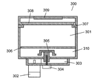
- the microwave heating cooker 300 includes a magnetron 302, a waveguide 303, a heating chamber 301, a mounting table 306, a power feeding unit (antenna space) 310, a rotating antenna 305, a motor 304, a heating dish 308, a dish receiving unit 307, and a heater. 309.
- Magnetron 302 is a typical microwave generator.
- the waveguide 303 transmits the microwave radiated from the magnetron 302 to the heating chamber 301.
- a heating object such as food is placed inside, and is subjected to a heating operation using microwaves.
- the mounting table 306 is made of a low-loss dielectric material such as ceramic or glass having a property that microwaves can be easily transmitted, and is fixed in the heating chamber 301, on which a heating object is mounted.
- the power feeding unit 310 is an antenna space formed below the mounting table 306 in the heating chamber 301.
- the rotating antenna 305 is attached to the vicinity of the center of the heating chamber 301 from the waveguide 303 to the power feeding unit 310 in order to radiate the microwave in the waveguide 303 into the heating chamber 301.
- the motor 304 rotationally drives the rotating antenna 305.
- the heating dish 308 is installed in the heating chamber 301 according to the application, and the dish receiving unit 307 supports the heating dish 308.
- the heater 309 performs electrothermal heating.
- the microwave heating process is started with food or the like placed on the mounting table 306.
- Microwaves radiated from the magnetron 302 are radiated from the upper surface of the radiating portion of the rotating antenna 305 toward the heating chamber 301 through the waveguide 303 and the rotating antenna 305.
- the rotating antenna 305 radiates the microwaves while rotating at a constant speed (see, for example, Patent Document 1).
- the thawing function When performing the thawing function to heat the frozen food that is the object to be heated by microwave heating, first place the frozen food on a heat-resistant tray or flat plate, and place the tray or flat plate in that state on the mounting table 306. Put. Then, the thawing function is selected, and the operation of the microwave heating cooker is started. When the object to be heated reaches a predetermined temperature or when the operation is performed for a set time, the thawing operation ends (for example, see Patent Document 2).
- the microwave heating cooker 300 is provided with slit holes, which are a plurality of substantially rectangular openings provided around the heating dish main body, separately from the one configured as described above, and is mainly composed of ferrite. Some slit hole closing members made of rubber are provided detachably with respect to the slit holes (see, for example, Patent Document 3).
- a microwave heating cooker equipped with this slit hole when executing a thawing function for heating frozen food that is an object to be heated, the frozen food is placed on a heat-resistant tray or flat plate, and the tray or flat plate is mounted. Place on the table 306. Further, the slit hole closing member is attached and detached, the slit hole is opened, a menu is selected, and the operation of the microwave heating cooker is started. When the object to be heated reaches a predetermined temperature or when the operation is performed for a set time, the thawing operation ends.
- the desired effect can be obtained by the installed heating dish 308. I can't. That is, since there is almost no gap between the peripheral edge of the heating plate 308 and the inner wall of the heating chamber 301, the microwaves uniformly radiated from the power feeding unit 310 (rotating antenna 305) to the heating chamber 301 are generated on the heating plate 308. It is blocked by the lower surface and is difficult to go around to the upper surface side of the heating pan 308.
- the present invention provides a microwave heating that can automatically and continuously perform a thawing function and a grill function without a user's operation even when a heating pan on which an object to be heated is placed is set in a heating chamber.
- a cooker is provided.
- the present invention provides a heating chamber in which a door to which glass is attached is provided in the front opening and accommodates an object to be heated, a microwave transmissive mounting table that constitutes a bottom surface of the heating chamber, and a microwave absorber on the lower surface.
- a metal heating pan that is detachably attached to the heating chamber and places an object to be heated, a microwave generator, a waveguide that transmits the microwave from the microwave generator to the heating chamber, and a directivity
- a directional power supply unit that supplies the microwave from the waveguide to the heating chamber, a drive unit that rotationally drives the directional power supply unit, and the directional power supply unit facing the door.
- a control unit that controls the drive unit to supply microwaves to the space above the heating dish using the inside of the glass as a main transmission path, and a power feeding unit that is formed below the mounting table and accommodates the directional power feeding unit Part.
- the inside of the door can be used as a microwave transmission path without using an additional member or requiring processing of an existing member. That is, without making the configuration complicated, the dead space can be effectively used to increase the amount of microwaves that wrap around the heating pan.
- the desired cooking finish suitable for the kind of to-be-heated object is obtained, such as making a to-be-heated object absorb microwave directly, and heating efficiency can be improved. Therefore, the thawing function and the grilling function can be performed automatically and continuously without the user's operation in a state where the heating pan on which the object to be heated is placed is installed in the heating chamber.
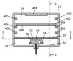
- FIG. 1 is a front sectional view showing an internal structure of a microwave oven that is a microwave heating cooker according to an embodiment of the present invention.
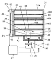
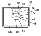
- FIG. 2 is a view showing a section 2-2 of the microwave oven in FIG. 3A is a 3-3 cross-sectional view of the microwave oven in FIG. 1 for explaining the orientation of the rotating waveguide in the present embodiment.
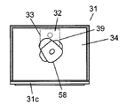
- FIG. 3B is another 3-3 cross-sectional view of FIG. 1 for explaining the direction of the rotating waveguide of the microwave oven in the present embodiment.
- FIG. 3C is still another 3-3 cross-sectional view of FIG. 1 for explaining the direction of the rotating waveguide of the microwave oven in the present embodiment.
- FIG. 4 is an explanatory diagram of the origin detection mechanism of the rotating waveguide of the microwave oven in the present embodiment.
- FIG. 5 is a configuration diagram showing the configuration of the control unit of the microwave oven in the present embodiment.
- FIG. 6 is a flowchart showing the operation of the microwave oven in the present embodiment.
- FIG. 7 is a diagram illustrating a configuration of a temperature detector used in the microwave oven according to the present embodiment.
- FIG. 8 is a plan view showing a modification of the rotating waveguide of the microwave oven in the present embodiment.
- FIG. 9A is a plan view illustrating a heating pan of the microwave oven in the present embodiment.
- FIG. 9B is a side view illustrating the heating pan of the microwave oven in the present embodiment.
- FIG. 9C is a cross-sectional view of 9C-9C in FIG. 9A for explaining the heating pan of the microwave oven in the present embodiment.
- FIG. 10A is an explanatory diagram of the orientation of the open portion of the rotating waveguide with respect to the heating dish of the microwave oven and the wrapping of the microwaves to the upper surface side of the heating dish in the present embodiment.
- FIG. 10B is another explanatory diagram of the direction of the opening portion of the rotating waveguide with respect to the heating dish of the microwave oven and the wrapping of the microwaves to the upper surface side of the heating dish in the present embodiment.
- FIG. 11A is an explanatory diagram of a method for confirming the amount of microwave wrapping around the heating pan of the microwave oven in the present embodiment.
- FIG. 11B is another explanatory diagram of a method for confirming the amount of microwave wrapping around the heating pan of the microwave oven in the present embodiment.
- FIG. 11A is an explanatory diagram of a method for confirming the amount of microwave wrapping around the heating pan of the microwave oven in the present embodiment.
- FIG. 11B is another explanatory diagram of a method for confirming the amount of microwave wrapping around the heating pan of the microwave oven in the present
- FIG. 11C is still another explanatory diagram of the method for confirming the amount of microwave wrapping around the heating pan of the microwave oven in the present embodiment.
- FIG. 12A is an explanatory diagram of the relationship between the direction of the opening of the rotating waveguide in the heating pan of the microwave oven according to the present embodiment and the amount of microwave wraparound.
- FIG. 12B is another explanatory diagram of the relationship between the direction of the opening portion of the rotating waveguide in the heating pan of the microwave oven according to the present embodiment and the amount of microwave wraparound.
- FIG. 13 is a diagram illustrating the relationship illustrated in FIG. 12B.
- FIG. 14 is a front sectional view showing an internal structure of a conventional microwave oven.
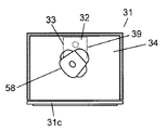
- the microwave oven 31 has a door 31b attached to a main body 31a.
- the main body 31 a is connected to a heating chamber 34 for storing a heated object such as food, a magnetron 32 for generating microwaves for cooking the heated object, and a magnetron 32 for guiding the microwave into the heating chamber 34.
- the waveguide 33 is built in.
- a front opening 38 is formed in the front surface of the heating chamber 34.
- the door 31b is attached to the main body 31a and is configured to cover the front opening 38 formed in the heating chamber 34 so as to be freely opened and closed.
- the door 31b may be attached to the main body 31a through a hinge or as a sliding type like a sliding door.
- the door 31b may be attached to the main body 31a so as to be pulled out.
- it When attached via a hinge, it may be attached to either the left side, the right side, or the lower side of the front opening 38.
- the door 31b includes a metal plate 60, an inner glass 61 and an outer glass 62 that sandwich the metal plate 60 in the front-rear direction, and a choke cover (not shown) that covers the outer periphery of the metal plate 60.
- a plurality of through holes are formed at positions facing the front opening 38 of the metal plate 60 so that the inside of the heating chamber 34 can be seen.
- a choke structure 63 is formed on the outer periphery of the metal plate 60.
- FIG. 2 illustrates a case where the choke structure 63 is formed by bending the metal plate 60 a plurality of times.
- the choke structure 63 is preferably formed by bending a plurality of end portions formed in a comb shape by a plurality of slits formed at the end of the metal plate 60 and provided at predetermined intervals.
- the number of slits is not particularly limited.
- the inner glass 61 plays a role of constituting one surface of the heating chamber 34 when the door 31b is closed.
- the inner glass 61 makes the inside of the heating chamber 34 visible when the door 31b is closed.
- the outer glass 62 plays a role of constituting the outer surface of the door 31b. As with the inner glass 61, the outer glass 62 also makes the heating chamber 34 visible when the door 31b is closed.
- the microwave oven 31 includes a mounting table 35, a power feeding unit (antenna space) 37, a rotating waveguide 39, a motor 41, a control unit 411, and a photo interrupter 36.
- the heating chamber 34 is connected to the upper portion of the waveguide 33 and forms a space having a shape whose width direction dimension (about 400 mm) is larger than the depth direction dimension (about 310 mm).
- the mounting table 35 is made of a low-loss dielectric material such as ceramic or glass having a property that allows microwaves to easily pass through.
- the mounting table 35 is provided inside the heating chamber 34 for mounting food (not shown) as a typical object to be heated. Fixed to.
- the power feeding unit 37 is formed below the mounting table 35 in the heating chamber 34.
- the rotating waveguide 39 is attached in the power feeding unit 37 and radiates the microwave in the waveguide 33 into the heating chamber 34.
- the motor 41 is a drive unit that rotationally drives the rotary waveguide 39.
- the control unit 411 is a control unit that controls the rotation and direction of the rotary waveguide 39 by controlling the motor 41.
- the photo interrupter 36 constitutes an origin detection mechanism that detects the origin of rotation of each rotary waveguide 39.
- the rotating waveguide 39 is a directional power supply unit that has the open portion 58 shown in FIGS. 3A to 3C and can radiate microwaves in a concentrated manner in the direction in which the open portion 58 faces.
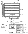
- a heater 401 capable of performing electrothermal heating is installed on the upper surface portion of the heating chamber 34.
- the heating chamber 34 has three stages of dish receivers that support the heating dish 402. Specifically, the heating chamber 34 includes an upper tray receiver 403, an intermediate tray receiver 404, and a lower tray receiver 405.
- the upper tray receiver 403, the middle tray receiver 404, and the lower tray receiver 405 are collectively referred to as a tray 400.
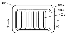
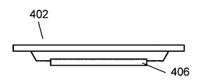
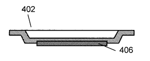
- FIG. 9A shows a plan view of the heating dish 402 as seen from above.
- FIG. 9B shows a side view of the heating dish 402 as viewed from the side.
- FIG. 9C shows a 9C-9C cross-sectional view in FIG. 9A.
- the heating dish 402 includes a frame-shaped peripheral portion 402a and a plate 402c formed inside thereof and having a plurality of grooves 402b (not shown in FIG. 9C) having a predetermined depth formed in parallel.
- An object to be heated is placed on the plate 402 c and placed in the heating chamber 34.
- the microwave absorber 406 (for example, ferrite) is provided in the back surface side (mounting table 35 side) of a plate.
- the operation part 31c is arrange
- the operation unit 31c is a device that allows the user to select various cooking menus according to food and cooking contents.
- the operation unit 31c can be used to set a heating time, or to select a preset automatic cooking menu such as “warming function”, “thaw function”, “thaw / grill function”, and “grill function”.
- Warming function refers to a cooking method that heats food by radiating microwaves toward the food.
- Derosting function means frozen food by a method in which microwaves are continuously or intermittently radiated and heated in frozen food, a method in which frozen food is heated and thawed by steam, or a method in which food is thawed by a combination thereof. This means the heating method.
- the “thaw / grill function” refers to the direction of the front opening 38 of the heating chamber 34, which is a direction in which the opening 58 of the rotating waveguide 39 easily goes around the upper surface of the heating dish, or the peripheral edge of the heating dish 402 and the inner wall of the heating chamber 34.
- the frozen food placed on the heating dish 402 is absorbed in the microwave in any direction of the gap direction with the microwave and thawed, and then the thawed food is cooked by the “grill function” described later. That means.
- the open portion 58 of the rotating waveguide 39 is directed to the front opening 38 of the heating chamber 34, and heating is performed by performing a heating plate upper surface heating mode in which a large amount of supply is performed in the microwave supply to the upper surface of the heating plate 402 After the frozen food placed on the plate 402 absorbs microwaves and thaws, the thawed food is subsequently cooked by the “grill function” described later.
- the “grill function” means that the microwaves are concentrated on the microwave absorber 406 on the back surface side of the heating dish 402 on which food is placed to generate heat at a high temperature. It refers to a cooking method in which food is heated through the heating dish 402, or a cooking method in which food is heated by a combination of the heated dish 402 and the heating heater.
- control unit 411 executes these menus by controlling the magnetron 32 and the motor 41.
- the microwave oven 31 controls the opening 58, which is a portion having a high radiation directivity, of the rotating waveguide 39 in a predetermined direction, and particularly in the “thaw / grill function”, the first half is a heating pan.
- the amount of microwave sneaking into the upper surface of 402 is increased to efficiently defrost.
- the microwaves are concentrated on the microwave absorber 406 on the back side of the plate of the heating dish 402 to efficiently generate heat. Specific control will be described later.
- the coupling portion 46 is made of a substantially cylindrical conductive material that passes through a substantially circular coupling hole (not shown) provided in the boundary surface between the waveguide 33 and the heating chamber bottom surface 42. ing.
- the radiating portion 48 is made of a conductive material having a larger area in the horizontal direction than the vertical direction, and is integrally connected to the upper end of the coupling portion 46 by caulking or welding.
- the rotating waveguide 39 includes a coupling portion 46 and a radiating portion 48.
- the rotating waveguide 39 is fitted to the shaft 50 of the motor 41 so that the center of the coupling portion 46 becomes the center of rotation driving.
- the radiating portion 48 has a radiation directivity because the shape is not constant with respect to the direction of rotation.
- the center of rotation of the rotating waveguide 39 is arranged at the center in the heating chamber 34.
- the radiating portion 48 is formed in a trapezoidal shape with the radiating portion upper surface 52 having the open portion 58 side as a bottom when viewed from above.
- the radiating portion upper surface 52 having the open portion 58 side as a bottom when viewed from above.
- three sides excluding the bottom side have radiation portion bent portions 54 bent toward the heating chamber bottom surface 42 (FIG. 1) side, and limit microwave radiation to the outside of the three sides. It is configured accordingly.
- the rotating waveguide 39 is also rotated at a constant speed as in the conventional case. Also good. Further, when it is possible to heat uniformly by stopping at an angle in the middle of rotation, the stop may be mixed. In this embodiment, the rotation is constant.
- the rotating waveguide 39 may be rotated and stopped at predetermined time intervals, or may be rotated at a constant speed. If it can be heated more uniformly, constant rotation may be used. In this embodiment, the rotation is constant.
- the operation is started in a state where the heating dish 402 on which the frozen food is placed is set in a predetermined tray 400, for example, the upper tray receiver 403.
- the opening 58 of the rotating waveguide 39 is directed to the front opening 38 of the heating chamber 34, and the microwave reaches the upper side of the heating dish 402 through the inner glass 61 of the door 31 b and is placed on the heating dish 402.
- the frozen food is thawed, and after the thawing, the food is cooked by the grill function.
- the opening 58 of the rotating waveguide 39 facing a predetermined position (for example, a direction different from the front opening 38).
- the operation of the rotating waveguide 39 may be stopped or may be rotated constantly.
- a predetermined stop position of the rotating waveguide 39 will be described with reference to FIGS. 3A to 3C.
- the angle information (stop position) of the rotating waveguide 39 is stored on the basis of the origin detected by the origin detection mechanism having the photo interrupter 36 by the control unit 411. As shown in FIG. 3A, when the open portion 58 of the rotating waveguide 39 is in the direction of the door 31b, it is 180 °, and when it is backward (not shown), it is the origin position (0 degree).
- the microwaves are concentrated and emitted to the inner glass 61 of the door 31b. Then, the radiated microwave passes through the gap between the heating dish 402 and the inner glass 61, the inside of the inner glass 61, and the gap space between the inner glass and the metal plate 60, and wraps around the heating dish 402.
- the inner glass 61 is a dielectric, and the wavelength of the microwave traveling through the dielectric is shortened to the inverse of the square root of the dielectric constant of the dielectric. Therefore, in the case of glass having a relative dielectric constant of 4 to 9, this corresponds to a space gap of about 2 to 3 times the plate thickness of the glass.
- the direction of the rotating waveguide 39 suitable for the “grill function” is not generally determined, but it should be different from at least the direction of the door 31b. Therefore, it is conceivable that an appropriate direction is obtained in advance by experiments and stored in the control unit 411.
- the heating pan 402 placed on the upper tray receiver 403
- the heating dish 402 is placed in the upper tray receiving unit 403 at the position (for example, 130 ° clockwise from the origin).
- the controller 411 stores the stop position of the rotating waveguide 39 in the “grill function” when it is opened.
- the open portion 58 of the rotating waveguide 39 is directed toward the left side surface of the heating chamber 34.
- the position (for example, 230 ° clockwise from the origin) is used for the middle stage. This is stored in the control unit 411 as the stop position of the rotating waveguide 39 of the “grill function” when the heating plate 402 is placed on the plate receiving unit 404.
- the microwave oven 31 controls the orientation of the rotating waveguide 39 according to the position of the heating dish 402.
- a method such as using a stepping motor as the motor 41 or detecting the reference position and controlling the energization time even if the motor rotates at a constant speed is considered. It is done.
- an origin detection mechanism is provided on the shaft 50 of the stepping motor used as the motor 41.
- the origin detection mechanism includes a disc 36 a having the shaft 50 as a central axis and a photo interrupter 36.
- the circular plate 36a is provided with a rectangular slit 36b.
- the disc 36a is attached to the shaft 50 of the motor 41 that rotates the rotating waveguide 39, and rotates so as to block the optical path of the photo interrupter 36 that includes a light emitting element and a light receiving element.
- the control unit 411 includes an antenna control unit 412 and a storage unit 413.
- the antenna control unit 412 controls the operation of the rotating waveguide 39 by controlling the operation of the motor 41.
- the storage unit 413 stores position information (angle information) of the rotating waveguide 39.
- the antenna control unit 412 refers to necessary information from the storage unit 413 according to a command signal from the operation unit 31c, controls the motor 41, and controls the operation of the rotating waveguide 39.
- the storage unit 413 is suitable for heating the heating dish 402 for each position where the heating dish 402 is placed in the heating chamber 34 (upper stage, middle stage, lower stage), the positional information of the rotating waveguide 39 suitable for thawing.
- the position information of the rotating waveguide 39 is stored. Specifically, position information 414 for thawing at the upper stage (180 ° clockwise from the origin), position information 415 for the grill at the upper stage (130 ° clockwise from the origin), and for the grill at the middle stage Position information 416 (230 ° clockwise from the origin) is stored.
- the microwave oven 31 is turned on and enters a standby state in step S102.
- step S102 the user enters a menu selection acceptance state using the operation unit 31c.
- the operation unit 31c outputs a menu signal Sm corresponding to the menu selection selected by the user to the control unit 411.
- the user selects a “warming function”, “thaw / grill function”, “grill function”, or other menu depending on the content (type of food) to be heated.
- the menu includes the position (upper, middle or lower) where the heating pan 402 is placed.
- the operation unit 31 c When it is determined that the “warming function” is selected, the operation unit 31 c outputs a menu signal SmA indicating the “warming function” to the antenna control unit 412. Then, the control proceeds to step S103.
- step S103 the antenna control unit 412 rotates the rotating waveguide 39 at a constant speed by rotating the motor 41 at a constant speed in response to the menu signal SmA. Then, the control proceeds to the next Step S104.
- step S104 the control unit 411 operates the magnetron 32 to start the heat treatment. Then, the control proceeds to the next Step S105.
- step S105 the timer starts timing. After the elapse of the first predetermined period P1 is confirmed, the control proceeds to the next step S106.
- step S106 the operation of the magnetron 32 or the like is stopped, and the heating process by the “warming function” is completed.
- step S102 when “defrost / grill function” is selected, the operation unit 31c outputs a menu signal SmB indicating that “defrost / grill function” is selected to the antenna control unit 412. Then, the control proceeds to the next Step S107.
- step S107 based on the menu signal SmB, the antenna control unit 412 determines whether the position where the heating pan 402 is placed is the upper stage. Note that the “thaw / grill function” allows you to select types such as meat, fish, and pizza. Then, the control proceeds to the next Step S108.
- step S108 the antenna control unit 412 controls the operation of the motor 41 with reference to the corresponding position information from the storage unit 413 based on the position information determined in step S107. Specifically, the antenna control unit 412 refers to the position information 416 in the storage unit 413 based on the position information in the menu signal Sm determined in S107. As a result, the antenna control unit 412 allows the rotating waveguide 39 to rotate and stop in a direction in which microwaves easily reach the upper surface of the heating dish 402, for example, in the direction of the front opening 38 (180 °). Control the behavior. Then, the control proceeds to the next Step S109.
- step S109 with the rotating waveguide 39 stopped at the predetermined position controlled in S108, the control unit 411 operates the magnetron 32 and starts the heat treatment. Then, the control proceeds to the next Step S110.
- step S110 after a predetermined stop time has elapsed, the rotary waveguide 39 is rotated again to make a full turn, and is stopped at 180 ° for a predetermined time. Thus, the rotation and the 180 ° stop are repeated. Then, the control proceeds to the next Step S111.
- step S111 the timer starts timing. After the elapse of the second predetermined period P2 is confirmed, control proceeds to the next step S112. During this time, the state in which microwaves are likely to wrap around the upper side of the heating dish continues, so that the food can be thawed efficiently.
- step S112 it is determined whether or not the thawing is completed. If the thawing has not been completed (No in S112), the thawing is continued, and it is determined in step S112 whether the thawing has been completed. This is repeated until thawing is complete. If the thawing is completed (Yes in S112), the process proceeds to step S113 in order to continue the “grill function” since the thawing has been completed. After this, in order to bake the food, the process should be shifted to the “grill function”, which is the same as the case where the “grill function” is selected in the above-described step S102 (that is, the food that is not originally frozen is baked). Bake it.
- step S102 when “grill function” is selected, the operation unit 31c outputs a menu signal SmC indicating that “grill function” is selected to the antenna control unit 412. Then, the control proceeds to the next Step S113.
- the menu signals SmA and SmB described above and the menu signal SmC are collectively referred to as a menu signal Sm.
- step S113 based on the menu signal SmC, the antenna control unit 412 determines whether the position where the heating pan 402 is placed is the upper, middle or lower stage.
- the “grill function” allows selection of the type of grilled food such as fish, bird's thigh, roast beef or roast chicken, pizza or paella.
- the position of the plate is stored in advance in the upper, middle and lower stages, and the position of the plate is selected by selecting the type of food to be grilled with the "grill function". Determine.
- the present invention is not limited to this, and for example, a detector may be provided in each of the tray receivers 403 to 405, and the tray position may be determined based on a signal from this detector. Then, the control proceeds to the next Step S114.
- step S114 based on the menu signal SmC, the antenna control unit 412 refers to the corresponding position information from the storage unit 413, and controls the operation of the motor 41. For example, when the grill function is selected on the upper stage by the operation unit 31c, the antenna control unit 412 refers to the upper position information 415 and rotates the rotating waveguide 39 clockwise from the origin to a position of 130 °. Then, the operation of the motor 40 is controlled to stop at that position. Then, the control proceeds to the next Step S115.
- step S115 the control unit 411 operates the magnetron 32 while starting the heat treatment while the rotary waveguide 39 is stopped. Then, the control proceeds to the next Step S116.
- step S116 after the predetermined stop time of the rotating waveguide 39 has elapsed, the rotating waveguide 39 is rotated again to make one turn, and is stopped at 130 ° for a predetermined time. In this way, the rotation and the 130 ° stop are repeated. Next, the process proceeds to step 117.
- step S117 the timer starts measuring time, and after the elapse of the third predetermined period P3 is confirmed, control proceeds to the next step S118. During this time, the state where the microwave tends to concentrate on the ferrite on the back surface of the heating dish continues, so that the heating dish is heated and the bottom surface of the food can be efficiently baked.
- step S118 the magnetron 32 is stopped, and in the next step S119, the heater 401 is driven this time. Then, in the next step S120, the timer starts measuring time, and after the elapse of the fourth predetermined period P4 is confirmed, the control proceeds to the next step 106. During this time, the upper surface of the food can be efficiently baked by the heater 401.
- step S106 after the operations of the rotating waveguide 39, the heater 401, the magnetron 32, and the like are stopped, the heating process of the “grill function” ends.
- the microwave oven 31 has the three-stage (upper, middle, and lower) tray receivers 403 to 405 in the heating chamber 34, and the cooking menu depends on the position of the tray receiver. And various foods can be cooked with the “grill function”.
- the upper stage (dish receiving part 403), it is used when cooking traditionally grilled with thin ingredients such as fish and chicken thighs.
- the middle stage (dish receiving portion 404), it is used when cooking a large food such as roast beef or roast chicken.
- the upper surface can improve the cooking performance by taking a distance from the upper surface heater because the heating power may be soft. .
- the lower surface of the cooked food by causing the ferrite which is the microwave absorber 406 attached to the lower surface of the heating dish 402 to absorb the microwave and generate heat.
- the upper surface of the cooked food can be cooked by heating the heater 401 with the heater 401 disposed on the upper surface of the heating chamber 34.
- the stop position of the rotating waveguide 39 of the microwave heating cooker is controlled by the position of the dish receiving portion.
- the temporary stop position of the rotating waveguide 39 is different.
- the stop position is obtained in advance by experiments as described above, and the storage unit 413.
- the motor 41 By providing the motor 41 with the origin detection mechanism, it is possible to accurately control the stop position of the rotating waveguide 39, and the most efficient heating can be realized at the respective positions of the tray receivers 403 to 405.
- the amount of microwaves propagating to the upper space of the heating dish 402 (the space where the food is placed) is reduced, so that the moisture inside the food is excessively evaporated. Can be prevented.
- the antenna control unit 412 of the control unit 411 may reciprocally swing the rotating waveguide 39 about a predetermined angle (for example, ⁇ 5 degrees) around the target angle (stop position).
- a predetermined angle for example, ⁇ 5 degrees
- This reciprocating rocking operation may be performed from the start of heating, or may be configured to start after a predetermined time has elapsed from the start of heating (for example, after 30 seconds to 1 minute).
- control unit 411 includes a stop upper limit time storage unit that stores in advance an upper limit time that allows the rotating waveguide 39 to stop, and the rotating waveguide stops. And a reciprocal angle storage unit that stores an angle at which the rotary waveguide 39 is reciprocally swung.
- the rotating waveguide 39 may be rotated by a predetermined angle (for example, 5 degrees) after a predetermined time has elapsed (for example, after 30 seconds to 1 minute) from the start of heating when the grill function is performed.
- a predetermined angle for example, 5 degrees
- a predetermined time for example, after 30 seconds to 1 minute
- the rotation speed of the rotating waveguide 39 may be controlled.
- the structure may be such that the microwave is concentrated on the heating dish 402 by rotating the rotating waveguide 39 slowly in the vicinity of a predetermined position and rotating the others at a constant speed.
- an experiment is performed in advance to determine beforehand in which position the microwave is concentrated on the heating dish by controlling the rotating waveguide at which speed.
- control unit 411 stores the time when the rotary waveguide 39 is at a predetermined stop position (angle) as the origin. Then, for example, the control unit 411 executes an origin detection mode for confirming the origin of the rotating waveguide 39 together with the “warming function” and the “grill function” before or after the heat treatment.
- the control unit 411 performs control to stop the operation of the magnetron while driving the rotary waveguide 39 in the origin detection mode.
- control unit 411 performs the origin detection mode after the end of the heating process, and waits for non-heating with the origin detected. Thereby, it is possible to prevent the standby time for detecting the origin from occurring before starting the heat treatment.
- FIG. 7 shows an example of a temperature detector for detecting the temperature distribution.
- the temperature detector 10 includes an infrared detection element 13, a case 18, and a stepping motor 11.
- the infrared detection elements 13 are provided in a line on the substrate 19, the case 18 accommodates the entire substrate 19, and the stepping motor 11 causes the case 18 to cross the direction perpendicular to the direction in which the infrared detection elements 13 are aligned. Move.
- a metal can 15 enclosing the infrared detection element 13 and an electronic circuit 20 for processing the operation of the infrared detection element 13 are provided.
- the can 15 is provided with a lens 14 through which infrared rays pass.
- the case 18 is provided with an infrared passage hole 16 through which infrared rays pass and a hole 17 through which lead wires from the electronic circuit 20 pass.
- the case 18 can be moved in a direction perpendicular to the direction in which the infrared detection elements 13 are aligned.
- the stepping motor 11 of the temperature detector reciprocates, the temperature distribution in almost all regions in the heating chamber 34 can be detected.
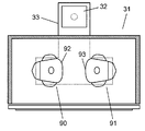
- the number of rotating waveguides 39 is not limited to this and may be two or more.
- two rotating waveguides 90 and 91 may be provided in the width direction of the heating chamber 34.
- the open portions 92 and 93 of the rotating waveguides 90 and 91 are arranged so as to face the vicinity of the center in the heating chamber 34. Even in this case, in an experiment in advance, in which positional relationship between the two rotary waveguides 90 and 91, whether the microwave easily wraps around the heating dish 402, or whether the microwave concentrates on the heating dish 402 Should be obtained in advance through experiments.
- the number of combinations of stopping positions of the rotating waveguides 90 and 91 increases (for example, one rotating waveguide 90 is the origin position and the other rotating waveguide 91 is the other). Is 90 degrees counterclockwise from the origin), and the variable range of microwave control is widened. Therefore, it is possible to more efficiently circulate microwaves to the upper side of the heating dish 402 or to concentrate microwaves on the heating dish 402. As a result, the heating efficiency of the “thawing / grill function” and the heating efficiency of the grill can be improved. On the other hand, it becomes possible to intensively heat the right half or the left half of the heating dish 402, and the upper half or the lower half area, and the variety of cooking methods is widened.
- microwaves are radiated into the heating chamber 34 from below the heating chamber 34, but a power feeding unit 37 is provided above the heating chamber 34, and microwaves are radiated from above the heating chamber 34, Microwaves may wrap around the lower surface of 402.
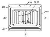
- FIG. 10A shows a state where the heating dish 402 (FIG. 9) set in the tray part 400 of the heating chamber 34 is viewed from above.
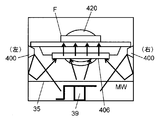
- FIG. 10B shows a state in which the food placed on the heating dish 402 is heated by microwaves as seen from the direction of the inner glass 61 of the door 31b.
- the rotating waveguide 39 faces the horizontal direction of the microwave oven 31, that is, the direction parallel to the door 31b.
- the microwave MW radiated from the magnetron 32 is substantially perpendicular to the left and right inner walls of the heating chamber 34 via the opening 58 of the rotating waveguide 39, and the door 31b and the rear wall protrusion 420 ( Radiated in a direction generally parallel to the circulation fan unit housing). For this reason, most of the microwave radiated into the heating chamber 34 is reflected by the left and right side walls of the heating chamber 34, the saucer 400, and the like, and finally is almost absorbed by the microwave absorber 406. And it is converted into heat by the microwave absorber 406 and the food F is directly heated from below.
- the opening 58 of the rotating waveguide 39 is positioned in a direction substantially perpendicular to the door 31b, and the microwave is projected to the door 31b or the rear wall. Radiating to the part 420. As described above, there are gaps between the heating dish 402 and the door 31b and between the heating dish 402 and the side wall on the rear wall protrusion 420 side.
- microwaves radiated from the opening 58 of the rotating waveguide 39 are heated via the gap between the heating dish 402 and the door 31b and the gap between the heating dish 402 and the side wall on the rear wall protrusion 420 side.
- the temperature reaches 402 and reaches the upper side of the heating chamber 34.
- the microwave is reflected by the inner wall of the heating chamber 34 and is used to heat the article to be heated (food) placed on the upper tray receiver 403. That is, the space generated between the heating dish 402 and the inner wall of the heating chamber 34 that is caused by the door 31b and the rear wall protrusion 420 is used as a main transmission path for supplying microwaves to the upper surface of the heating dish 402. Yes.
- the door 31b is provided with the inner glass 61 that functions as a transmission path corresponding to a space gap distance of about 2 to 3 times the plate thickness of the door 31b.
- the upper side of 402 can be supplied.
- the rotary waveguide 39 is first set so that the opening 58 faces the door 31b. Position. In this state, microwaves are supplied for a predetermined first heating time T1, and microwaves are supplied to the upper surface side of the heating dish 402 in the heating chamber 34 to thaw frozen food and the like. Then, if necessary, next, the rotating waveguide 39 is moved (rotated) so that the opening 58 is oriented parallel to the door 31b, and microwaves are supplied for a predetermined second heating time T2. . Accordingly, the microwave absorber 406 can generate heat, and the thawed food can be heated or baked from below.
- the microwaves are first put together (first predetermined time T1), the microwave is supplied to the upper side of the heating dish 402, and the frozen food is thawed from above, and then the microwave is supplied to the microwave absorber 406.
- second predetermined time T2 By supplying all together (second predetermined time T2), the thawed frozen food is heated from below.
- the position of the opening 58 may be changed intermittently or intermittently.
- the first heating time T1 is continuously continued, and the opening 58 is not stopped in a direction parallel to the door 31b, but is stopped only for a time shorter than the first heating time, and the frozen food is thawed slightly.
- the opening 58 is positioned in a direction perpendicular to the door 31b and heated (grilled) by the microwave absorber 406 for a time shorter than the second heating time T2. This operation is repeated.
- the total time of direct heating (thawing) by the microwave and the total time of heating (grill) by the microwave absorber 406 do not necessarily have to be the same as the first and second heating times T1 and T2. It is determined.
- the rotating waveguide 39 may be rotated at a constant speed without stopping the opening 58 in a predetermined direction.
- heating by the microwave supplied to the upper surface of the heating dish 402 (defrosting function) and heating by the microwave absorber 406 on the lower surface of the heating dish 402 (grill function) are continuous. Alternately.
- the direction of the opening 58 of the rotating waveguide 39 in the heating chamber 34 and the microwave are supplied to the upper side of the heating dish 402. Describe the relationship with quantity.
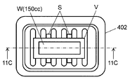
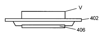
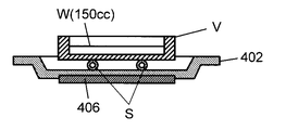
- the amount of microwaves radiated on the lower surface side of the heating plate 402 and wraps around the upper surface side of the heating plate 402 through the gap (mainly the inner glass 61) between the heating plate 402 and the inner wall (including the door 31b) of the heating chamber 34 is This can be confirmed by the method shown in FIGS. 11A to 11C.
- 11A to 11C correspond to FIGS. 9A to 9C, respectively.
- the amount of microwaves can be confirmed by the temperature of the water placed on the upper surface of the heating dish 402.
- an insulator is placed on the upper surface of the heating dish 402 as a spacer S for heat insulation.
- a resin container V in which 150 cc of water W is stored is placed thereon.
- the heat insulating spacer S prevents heat from the heating dish 402 from being conducted to the water W through the resin container V, and measures the temperature rise of the water W only by the wrapping microwaves. It is used for.
- 12A is a plan view of the heating pan 402 placed inside the heating chamber 34 as shown in FIG. 10A.
- the front is the door 31b side
- the back is the rear wall protrusion 420 (circulation fan unit storage) side
- the right is the right inner wall side of the heating chamber 34
- the left is the left inner wall side of the heating chamber 34.
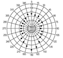
- the direction of the rotating waveguide 39 (open portion 58) having strong directivity is represented by an angle.
- the direction toward the rear wall protrusion 420 (circulation fan unit storage) is the reference (0 °), and the clockwise direction when viewed from above is the + side.
- the difference from the reference is graphed in 15 ° increments with the wraparound amount in the case of rotation as a reference. From the figure, it can be seen that the directivity is the largest at the front (door 31b side) of 180 °, the next is the rear (the rear wall protrusion 420 side), and the left and right are small.
- FIG. 13 shows the difference between the direction of the opening 58, the amount of wraparound of the microwave, and the rotation. That is, in the case where the rotating waveguide 39 is held at a position where the opening 58 is directed to the door 31b (inner glass 61) side, the microwave radiated from the rotating waveguide 39 is efficiently directed toward the heating dish 402. It turns out that it can supply. Even when the opening 58 is directed toward the rear wall protrusion 420 (circulation fan unit storage), the amount of microwave wrap-around is greater than when the opening 58 is directed toward the left and right inner walls.
- the rotating waveguide 39 is The stop position (angle) and time can be determined appropriately.
- the control unit 411 radiates the microwave MW from the opening unit 58 at the first position D1 where the amount of wraparound of the microwave MW is large for the first predetermined time T1, and the microwave MW.
- the microwave MW By radiating the microwave MW for the second predetermined time T2 at the second position D2 where the amount of wraparound is small, the frozen food can be continuously cooked from thawing while being placed on the heating dish 402.
- the first position D1 is a 180 ° or 0 ° position in FIG. 12B
- the second position D2 is a 90 ° or 270 ° position.
- the first position D1 and the second position D2 can be determined as appropriate for each microwave oven 31.
- the controller 411 continuously radiates the microwave MW for the first predetermined time T1 at the first position D1, and then continuously radiates the microwave MW for the second predetermined time T2 at the second position D2. You may let them. Further, the control unit 411 continuously radiates the microwave MW at the first position D1 for the first small heating time ⁇ T1 that is shorter than the first predetermined time T1, and then at the second position D2, the second predetermined time.
- the total of the first small heating time ⁇ T1 and the second small heating time ⁇ T2 means that the microwave MW is continuously emitted for the second small heating time ⁇ T2 that is smaller than the time T2 is the first predetermined time T1. The process may be repeated until the second predetermined time T2 or longer.
- the form using the heating tray 402 provided with the microwave absorber 406 was demonstrated.
- a case where a heat-resistant tray not provided with the microwave absorber 406 is used instead of the heating dish 402 can be considered. Even in this case, the same effect as that of the present invention in which the inside of the door is used as a microwave transmission path, the direction of the rotating waveguide 39 is controlled, and the amount of microwave wrapping up the tray is adjusted. can get.
- a temperature detection unit that detects the temperature of the object to be heated is provided, and only when the temperature of the object to be heated is low and it is determined that the object is a frozen product, the control unit 411 rotates the rotating waveguide 39 as a directional power supply unit. May be stopped toward the door 31b.
- the thawing function can be utilized to increase the amount of microwave wrapping around the heating dish 402 and efficiently defrost.
- the rotating waveguide 39 may be efficiently baked using the grill function without stopping the rotating waveguide 39 toward the door 31b.
- a weight detection unit that detects the weight of the object to be heated is provided, and in particular when the weight of the object to be heated is determined to be heavy, the control unit 411 stops the rotating waveguide 39 toward the door 31b. May be.
- the weight is heavy, it is considered that the size is generally large.
- the central portion tends to be difficult to be heated only by heat conduction. In this case, it is considered that heating to the central part is easier when heated by microwaves. Therefore, the rotating waveguide 39 is stopped in the direction of the door, and the amount of microwave wrapping around the heating pan can be increased to efficiently heat a large one to the center.
- the rotating waveguide 39 may be efficiently baked using the grill function without stopping the rotating waveguide 39 in the direction of the door.
- a misuse determination unit can be provided as a safety measure in case of misuse such as using a dish other than the heating dish 402. .
- the control unit 411 may continue to rotate the rotating waveguide 39 without stopping.
- the control unit 411 can stop the rotating waveguide 39 in the direction of the door and wrap around the heating dish to efficiently absorb the food. .
- the microwave absorber 406 for absorbing microwaves is provided on the lower surface of the heating dish, all microwaves in the heating chamber can be consumed safely.
- the regular heating dish 402 When the regular heating dish 402 is not used, for example, only the food is placed on the mounting table without the heating dish 402, a metal dish different from the heating dish 402 is placed, or the heating dish 402 and the food are both forgotten. It is also possible that misuse such as starting under load conditions will occur. In particular, when a metal dish different from the heating dish 402 is inserted, there is nothing that can absorb microwaves on the lower surface of the metal dish, and there is nothing that can absorb microwaves under no-load conditions. At this time, the electric field in the heating chamber 34 becomes strong, but if the rotating waveguide 39 is further stopped, there is a possibility that the strong electric field concentrates on a part. Therefore, when the heating dish 402 is determined to be misused, it is possible to prevent a strong electric field from concentrating on a part by continuing to rotate the rotating waveguide 39 without stopping.
- the microwave output may be reduced or stopped.
- the heating dish 402 may press a switch when the heating dish 402 is attached to the heating chamber 34. When a switch is arranged at the mounting position at the end of the heating dish 402 and the switch is not pressed, it can be determined that the regular heating dish 402 is not used.
- a temperature detection unit that detects the temperature of at least one of the heating dish 402 or the object to be heated may be provided. When a temperature different from the predetermined temperature is detected, it can be determined that the regular heating dish 402 is not used and misused.
- a weight detection unit that detects the weight of at least one of the heating dish 402 and the object to be heated may be provided. When a weight different from the predetermined weight is detected, it can be determined that the regular heating dish 402 is not used and misused.
- the present invention can be continuously heated from thawing, it can be used for a microwave heating apparatus such as a microwave oven.
Abstract
Description
以下に、図1~図13を参照して、本発明の実施の形態に係るマイクロ波加熱調理器について電子レンジを例として説明する。 (Embodiment)
Hereinafter, a microwave heating cooker according to an embodiment of the present invention will be described with reference to FIGS. 1 to 13 using a microwave oven as an example.
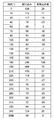
但し、本実施の形態においては、C=1、m=150gである。 P = 4.19 × m × C × ΔT / t (1)
However, in the present embodiment, C = 1 and m = 150 g.
=140[W] ・・・・(2)
次に、図12A、図12Bを参照して、回転導波管39の開放部58の向きと、マイクロ波の回り込み量の関係(開放部58の向きに対するマイクロ波の指向性)について説明する。図12Aは、図10Aで示したように、加熱室34の内部に載置された加熱皿402の平面図である。同図において、手前がドア31b側で、奥が後壁突出部420(循環ファンユニット格納部)側で、右が加熱室34の右内壁側、左が加熱室34の左内壁側である。回転導波管39の開放部58から見るこれらの方向をそれぞれ、180°、0°、90°、及び270°とする。 P = 4.19 × 150 × 1 × (60-20) / 180
= 140 [W] (2)
Next, with reference to FIG. 12A and FIG. 12B, the relationship between the direction of the
31a 本体
31b ドア
31c 操作部
32 マグネトロン(マイクロ波発生器)
33 導波管
34 加熱室
35 載置台
37 給電部
38 前面開口
39 回転導波管(指向性給電部)
41 モータ
42 加熱室底面(載置台)
58 開放部
60 金属板
61 内側ガラス(ガラス)
62 外側ガラス
90 回転導波管
91 回転導波管
92 開放部
93 開放部
400 受皿部
402 加熱皿(トレイ)
402a 周囲部
402b 溝
402c プレート
403 上段用皿受部
404 中段用皿受部
405 下段用皿受部
406 マイクロ波吸収体
411 制御部
412 循環ファンユニット格納部
420 後壁突出部 31 Microwave oven (microwave heating device)
33
41
58
62
402a
Claims (14)
- ガラスを取り付けたドアを前面開口に設け被加熱物を収納する加熱室と、
前記加熱室内の底面を構成するマイクロ波透過性の載置台と、
前記加熱室に着脱可能に装着し被加熱物を載置するトレイと、
マイクロ波発生部と、
前記マイクロ波発生部からのマイクロ波を前記加熱室に伝送する導波管と、
指向性を有し前記導波管から前記マイクロ波を前記加熱室に供給する指向性給電部と、
前記指向性給電部を回転駆動する駆動部と、
前記指向性給電部を前記ドアの方向に向け前記ガラス内を主伝送経路として前記トレイの上方の空間に前記マイクロ波を供給するよう前記駆動部を制御する制御部と、
前記載置台より下方に形成されて前記指向性給電部を収容する給電部と
を備えたマイクロ波加熱調理器。 A heating chamber in which a door fitted with glass is provided in the front opening to store an object to be heated;
A microwave-permeable mounting table constituting the bottom surface of the heating chamber;
A tray that is detachably mounted in the heating chamber and places an object to be heated;
A microwave generator,
A waveguide for transmitting microwaves from the microwave generation section to the heating chamber;
A directional power supply unit that has directivity and supplies the microwave from the waveguide to the heating chamber;
A drive unit that rotationally drives the directional power supply unit;
A control unit for controlling the driving unit to supply the microwave to the space above the tray with the directional power feeding unit facing the door and using the glass as a main transmission path;
The microwave cooking device provided with the electric power feeding part which is formed below the said mounting base and accommodates the said directional electric power feeding part. - 前記トレイが、下面にマイクロ波吸収体を設けた加熱皿である請求項1に記載のマイクロ波加熱調理器。 The microwave heating cooker according to claim 1, wherein the tray is a heating dish provided with a microwave absorber on a lower surface.
- 使用者の操作に応答して、使用者が選択する被加熱物の調理メニューを表すメニュー信号を出力する操作部をさらに備え、前記制御部が、前記メニュー信号に基づいて前記駆動部を制御して前記指向性給電部の向きを変え、前記トレイの上下の空間へのマイクロ波の供給量を制御する請求項1に記載のマイクロ波加熱調理器。 In response to a user operation, the apparatus further includes an operation unit that outputs a menu signal representing a cooking menu of the object to be heated selected by the user, and the control unit controls the drive unit based on the menu signal. The microwave heating cooker according to claim 1, wherein the direction of the directional power feeding unit is changed to control the amount of microwave supply to the space above and below the tray.
- 前記制御部が、前記指向性給電部が所定方向に向く位置で前記指向性給電部を停止させる請求項3に記載のマイクロ波加熱調理器。 The microwave heating cooker according to claim 3, wherein the control unit stops the directional power supply unit at a position where the directional power supply unit faces in a predetermined direction.
- 前記制御部が、前記指向性給電部が所定方向に向く位置の近傍で前記指向性給電部を揺動させる請求項3に記載のマイクロ波加熱調理器。 The microwave heating cooker according to claim 3, wherein the control unit swings the directional power supply unit in the vicinity of a position where the directional power supply unit is oriented in a predetermined direction.
- 前記制御部が、マイクロ波による加熱中、前記指向性給電部が所定方向の近傍で減速させつつ、前記指向性給電部を回転させる請求項3に記載のマイクロ波加熱調理器。 The microwave heating cooker according to claim 3, wherein the control unit rotates the directional power supply unit while the directional power supply unit decelerates in the vicinity of a predetermined direction during heating by microwaves.
- 前記所定方向が、前記ドアの方向である請求項4に記載のマイクロ波加熱調理器。 The microwave heating cooker according to claim 4, wherein the predetermined direction is a direction of the door.
- 前記制御部が、加熱調理運転の初期段階において、前記指向性給電部が所定方向に向く位置で前記指向性給電部を停止させる請求項4に記載のマイクロ波加熱調理器。 The microwave heating cooker according to claim 4, wherein the control unit stops the directional power feeding unit at a position where the directional power feeding unit faces in a predetermined direction in an initial stage of the cooking operation.
- 被加熱物の温度を検出する温度検出部をさらに備え、前記制御部が、前記被加熱物の温度に基づいて前記駆動部を制御して前記指向性給電部の向きを変え、前記トレイの上下の空間へのマイクロ波の供給量を制御する請求項1に記載のマイクロ波加熱調理器。 A temperature detection unit that detects a temperature of the object to be heated; and wherein the control unit controls the driving unit based on the temperature of the object to be heated to change the direction of the directional power supply unit. The microwave heating cooker of Claim 1 which controls the supply amount of the microwave to the space of.
- 被加熱物の重量を検出する重量検出部をさらに備え、前記制御部が、前記被加熱物の重量に基づいて前記駆動部を制御して前記指向性給電部の向きを変え、前記トレイの上下の空間へのマイクロ波の供給量を制御する請求項1に記載のマイクロ波加熱調理器。 A weight detection unit configured to detect the weight of the object to be heated; and the control unit controls the driving unit based on the weight of the object to be heated to change the direction of the directional power supply unit, and The microwave heating cooker of Claim 1 which controls the supply amount of the microwave to the space of.
- 前記トレイの誤使用と判定する誤使用判定部をさらに備え、前記誤使用判定部により前記トレイの誤使用と判定した場合は、前記制御部が、前記指向性給電部を回転させる請求項1に記載のマイクロ波加熱調理器。 The misuse determination part which determines that the said tray is misused is further provided, The said control part rotates the said directional electric power feeding part, when it determines with the misuse of the said tray by the said misuse determination part. The microwave heating cooker as described.
- 前記誤使用判定部が、前記トレイを加熱室に装着したときに前記トレイに押されるスイッチを有し、前記スイッチが押されない場合に前記トレイが使用されていない誤使用と判定する請求項11に記載のマイクロ波加熱調理器。 The said misuse determination part has a switch pushed by the said tray when the said tray is mounted in a heating chamber, and when the said switch is not pushed, it determines with the misuse that the said tray is not used. The microwave heating cooker as described.
- 前記誤使用判定部が、前記トレイまたは前記被加熱物の少なくとも一方の温度を検出する温度検出部を有し、所定の温度と異なる温度を検出した場合に前記トレイが使用されていない誤使用と判定する請求項11に記載のマイクロ波加熱調理器。 The misuse determination unit has a temperature detection unit that detects the temperature of at least one of the tray or the object to be heated, and the tray is not used when a temperature different from a predetermined temperature is detected. The microwave heating cooker of Claim 11 which determines.
- 前記誤使用判定部が、前記トレイまたは前記被加熱物の少なくとも一方の重量を検出する重量検出部を有し、所定の重量と異なる重量を検出した場合に前記トレイが使用されていない誤使用と判定する請求項11に記載のマイクロ波加熱調理器。 The misuse determination unit includes a weight detection unit that detects the weight of at least one of the tray or the object to be heated, and the tray is not used when a weight different from a predetermined weight is detected. The microwave heating cooker of Claim 11 which determines.
Priority Applications (3)
| Application Number | Priority Date | Filing Date | Title |
|---|---|---|---|
| EP09834343.7A EP2348257B1 (en) | 2008-12-25 | 2009-12-14 | Microwave cooking device |
| CN200980152516.5A CN102265092B (en) | 2008-12-25 | 2009-12-14 | Microwave cooking device |
| JP2010543804A JP5310741B2 (en) | 2008-12-25 | 2009-12-14 | Microwave heating cooker |
Applications Claiming Priority (6)
| Application Number | Priority Date | Filing Date | Title |
|---|---|---|---|
| JP2008329322 | 2008-12-25 | ||
| JP2008-329322 | 2008-12-25 | ||
| JP2008-329323 | 2008-12-25 | ||
| JP2008329323 | 2008-12-25 | ||
| JP2009-233608 | 2009-10-07 | ||
| JP2009233608 | 2009-10-07 |
Publications (1)
| Publication Number | Publication Date |
|---|---|
| WO2010073528A1 true WO2010073528A1 (en) | 2010-07-01 |
Family
ID=42287186
Family Applications (1)
| Application Number | Title | Priority Date | Filing Date |
|---|---|---|---|
| PCT/JP2009/006836 WO2010073528A1 (en) | 2008-12-25 | 2009-12-14 | Microwave cooking device |
Country Status (4)
| Country | Link |
|---|---|
| EP (1) | EP2348257B1 (en) |
| JP (1) | JP5310741B2 (en) |
| CN (1) | CN102265092B (en) |
| WO (1) | WO2010073528A1 (en) |
Cited By (7)
| Publication number | Priority date | Publication date | Assignee | Title |
|---|---|---|---|---|
| WO2011105110A1 (en) * | 2010-02-25 | 2011-09-01 | パナソニック株式会社 | Cooking device |
| JP2012042145A (en) * | 2010-08-20 | 2012-03-01 | Panasonic Corp | Heating cooker |
| JP2012047348A (en) * | 2010-08-24 | 2012-03-08 | Panasonic Corp | Cooking device |
| JP2016118344A (en) * | 2014-12-22 | 2016-06-30 | パナソニックIpマネジメント株式会社 | Microwave heating device |
| CN106248252A (en) * | 2016-07-28 | 2016-12-21 | 无锡信大气象传感网科技有限公司 | The meteorology Fibre Optical Sensor temperature calibration instrument being easily installed and overhauling |
| JP2017053533A (en) * | 2015-09-09 | 2017-03-16 | 日立アプライアンス株式会社 | Heating cooker |
| WO2022044719A1 (en) * | 2020-08-25 | 2022-03-03 | パナソニックIpマネジメント株式会社 | High frequency heating cooker |
Families Citing this family (8)
| Publication number | Priority date | Publication date | Assignee | Title |
|---|---|---|---|---|
| CN103512058A (en) * | 2012-06-29 | 2014-01-15 | 太仓南极风能源设备有限公司 | Microwave oven |
| CN103634959B (en) * | 2012-08-20 | 2015-12-02 | 侯梦斌 | A kind of microwave heating equipment with automatic loading and unloading raw material box alms bowl and technique |
| JP6414684B2 (en) * | 2014-12-22 | 2018-10-31 | パナソニックIpマネジメント株式会社 | Microwave heating device |
| EP3240363B1 (en) * | 2014-12-22 | 2020-08-26 | Panasonic Intellectual Property Management Co., Ltd. | Microwave heating device |
| JP6414683B2 (en) * | 2014-12-22 | 2018-10-31 | パナソニックIpマネジメント株式会社 | Microwave heating device |
| CN106052907A (en) * | 2016-07-28 | 2016-10-26 | 无锡信大气象传感网科技有限公司 | Temperature calibration device for meteorological detection optical fiber temperature sensor |
| CN111417226A (en) * | 2019-01-04 | 2020-07-14 | 青岛海尔股份有限公司 | Heating device |
| CN110996423B (en) * | 2019-12-30 | 2022-05-17 | 广东美的厨房电器制造有限公司 | Method, device and equipment for generating time distribution coefficient of microwave cooking equipment |
Citations (8)
| Publication number | Priority date | Publication date | Assignee | Title |
|---|---|---|---|---|
| JPS59200129A (en) * | 1983-04-28 | 1984-11-13 | Toshiba Corp | Cooking device |
| JPH09229372A (en) | 1996-02-23 | 1997-09-05 | Matsushita Electric Ind Co Ltd | High frequency heating device |
| JPH09306664A (en) * | 1996-05-08 | 1997-11-28 | Matsushita Electric Ind Co Ltd | High frequency heating device |
| JP2004071216A (en) | 2002-08-02 | 2004-03-04 | Sharp Corp | Microwave heating apparatus |
| JP2007139245A (en) * | 2005-11-16 | 2007-06-07 | Matsushita Electric Ind Co Ltd | High frequency heating cooking apparatus |
| JP2007225186A (en) | 2006-02-23 | 2007-09-06 | Matsushita Electric Ind Co Ltd | High frequency cooking heater |
| JP2007333362A (en) * | 2006-06-19 | 2007-12-27 | Matsushita Electric Ind Co Ltd | Micro-wave heating device |
| JP2007335377A (en) * | 2006-06-19 | 2007-12-27 | Matsushita Electric Ind Co Ltd | Microwave heating apparatus |
Family Cites Families (6)
| Publication number | Priority date | Publication date | Assignee | Title |
|---|---|---|---|---|
| JP3375803B2 (en) * | 1995-10-04 | 2003-02-10 | シャープ株式会社 | microwave |
| JP4655634B2 (en) * | 2005-01-14 | 2011-03-23 | パナソニック株式会社 | Microwave heating device |
| JP2008190752A (en) * | 2007-02-02 | 2008-08-21 | Mitsubishi Electric Corp | High frequency heating device |
| JP5034667B2 (en) * | 2007-05-14 | 2012-09-26 | パナソニック株式会社 | Microwave heating device |
| JP5003273B2 (en) * | 2007-05-15 | 2012-08-15 | パナソニック株式会社 | Microwave heating device |
| JP4916381B2 (en) * | 2007-05-18 | 2012-04-11 | パナソニック株式会社 | Induction heating cooker |
-
2009
- 2009-12-14 WO PCT/JP2009/006836 patent/WO2010073528A1/en active Application Filing
- 2009-12-14 CN CN200980152516.5A patent/CN102265092B/en active Active
- 2009-12-14 EP EP09834343.7A patent/EP2348257B1/en active Active
- 2009-12-14 JP JP2010543804A patent/JP5310741B2/en active Active
Patent Citations (8)
| Publication number | Priority date | Publication date | Assignee | Title |
|---|---|---|---|---|
| JPS59200129A (en) * | 1983-04-28 | 1984-11-13 | Toshiba Corp | Cooking device |
| JPH09229372A (en) | 1996-02-23 | 1997-09-05 | Matsushita Electric Ind Co Ltd | High frequency heating device |
| JPH09306664A (en) * | 1996-05-08 | 1997-11-28 | Matsushita Electric Ind Co Ltd | High frequency heating device |
| JP2004071216A (en) | 2002-08-02 | 2004-03-04 | Sharp Corp | Microwave heating apparatus |
| JP2007139245A (en) * | 2005-11-16 | 2007-06-07 | Matsushita Electric Ind Co Ltd | High frequency heating cooking apparatus |
| JP2007225186A (en) | 2006-02-23 | 2007-09-06 | Matsushita Electric Ind Co Ltd | High frequency cooking heater |
| JP2007333362A (en) * | 2006-06-19 | 2007-12-27 | Matsushita Electric Ind Co Ltd | Micro-wave heating device |
| JP2007335377A (en) * | 2006-06-19 | 2007-12-27 | Matsushita Electric Ind Co Ltd | Microwave heating apparatus |
Non-Patent Citations (1)
| Title |
|---|
| See also references of EP2348257A4 * |
Cited By (8)
| Publication number | Priority date | Publication date | Assignee | Title |
|---|---|---|---|---|
| WO2011105110A1 (en) * | 2010-02-25 | 2011-09-01 | パナソニック株式会社 | Cooking device |
| JP2012042145A (en) * | 2010-08-20 | 2012-03-01 | Panasonic Corp | Heating cooker |
| JP2012047348A (en) * | 2010-08-24 | 2012-03-08 | Panasonic Corp | Cooking device |
| JP2016118344A (en) * | 2014-12-22 | 2016-06-30 | パナソニックIpマネジメント株式会社 | Microwave heating device |
| TWI713411B (en) * | 2014-12-22 | 2020-12-11 | 日商松下知識產權經營股份有限公司 | Microwave heating device |
| JP2017053533A (en) * | 2015-09-09 | 2017-03-16 | 日立アプライアンス株式会社 | Heating cooker |
| CN106248252A (en) * | 2016-07-28 | 2016-12-21 | 无锡信大气象传感网科技有限公司 | The meteorology Fibre Optical Sensor temperature calibration instrument being easily installed and overhauling |
| WO2022044719A1 (en) * | 2020-08-25 | 2022-03-03 | パナソニックIpマネジメント株式会社 | High frequency heating cooker |
Also Published As
| Publication number | Publication date |
|---|---|
| CN102265092B (en) | 2014-05-07 |
| CN102265092A (en) | 2011-11-30 |
| EP2348257A4 (en) | 2015-05-06 |
| JPWO2010073528A1 (en) | 2012-06-07 |
| EP2348257A1 (en) | 2011-07-27 |
| JP5310741B2 (en) | 2013-10-09 |
| EP2348257B1 (en) | 2016-06-29 |
Similar Documents
| Publication | Publication Date | Title |
|---|---|---|
| JP5310741B2 (en) | Microwave heating cooker | |
| JP5116260B2 (en) | High frequency heating device | |
| EP2233838B1 (en) | Cooker | |
| EP2234456B1 (en) | Cooking device | |
| WO2009084169A1 (en) | Cooking device | |
| JP2009144970A5 (en) | ||
| JP4629085B2 (en) | Cooker | |
| JP2009129844A5 (en) | ||
| JP2011153780A (en) | High-frequency heating cooker | |
| JP2010002170A (en) | Cooker | |
| JP5593710B2 (en) | Microwave heating cooker | |
| CN109417839A (en) | With the improved multiple feeding type micro-wave furnace for drying crisp function | |
| WO2022044719A1 (en) | High frequency heating cooker | |
| JP5194561B2 (en) | Microwave heating device | |
| JP2010127469A (en) | Microwave heating device | |
| JP5899411B2 (en) | High frequency heating device | |
| JP5040426B2 (en) | Microwave heating device | |
| JP2011153750A (en) | High-frequency heating device | |
| JP2012154539A (en) | Heat cooking device | |
| JP2010255872A (en) | Heating cooker | |
| JP2008282693A (en) | Microwave heating apparatus | |
| JP2011204542A (en) | High frequency cooking device | |
| JP2014016068A (en) | Microwave heating device | |
| JP2014016069A (en) | Heated object loading means and microwave heating device using the same | |
| JP2013143251A (en) | Microwave heating apparatus |
Legal Events
| Date | Code | Title | Description |
|---|---|---|---|
| WWE | Wipo information: entry into national phase |
Ref document number: 200980152516.5 Country of ref document: CN |
|
| 121 | Ep: the epo has been informed by wipo that ep was designated in this application |
Ref document number: 09834343 Country of ref document: EP Kind code of ref document: A1 |
|
| DPE1 | Request for preliminary examination filed after expiration of 19th month from priority date (pct application filed from 20040101) | ||
| ENP | Entry into the national phase |
Ref document number: 2010543804 Country of ref document: JP Kind code of ref document: A |
|
| WWE | Wipo information: entry into national phase |
Ref document number: 2009834343 Country of ref document: EP |
|
| NENP | Non-entry into the national phase |
Ref country code: DE |