JP4629085B2 - Cooker - Google Patents
Cooker Download PDFInfo
- Publication number
- JP4629085B2 JP4629085B2 JP2007306314A JP2007306314A JP4629085B2 JP 4629085 B2 JP4629085 B2 JP 4629085B2 JP 2007306314 A JP2007306314 A JP 2007306314A JP 2007306314 A JP2007306314 A JP 2007306314A JP 4629085 B2 JP4629085 B2 JP 4629085B2
- Authority
- JP
- Japan
- Prior art keywords
- heated
- heating
- heating chamber
- antenna
- cooker
- Prior art date
- Legal status (The legal status is an assumption and is not a legal conclusion. Google has not performed a legal analysis and makes no representation as to the accuracy of the status listed.)
- Expired - Fee Related
Links
Images


Classifications
-
- H—ELECTRICITY
- H05—ELECTRIC TECHNIQUES NOT OTHERWISE PROVIDED FOR
- H05B—ELECTRIC HEATING; ELECTRIC LIGHT SOURCES NOT OTHERWISE PROVIDED FOR; CIRCUIT ARRANGEMENTS FOR ELECTRIC LIGHT SOURCES, IN GENERAL
- H05B6/00—Heating by electric, magnetic or electromagnetic fields
- H05B6/64—Heating using microwaves
- H05B6/72—Radiators or antennas
- H05B6/725—Rotatable antennas
-
- H—ELECTRICITY
- H05—ELECTRIC TECHNIQUES NOT OTHERWISE PROVIDED FOR
- H05B—ELECTRIC HEATING; ELECTRIC LIGHT SOURCES NOT OTHERWISE PROVIDED FOR; CIRCUIT ARRANGEMENTS FOR ELECTRIC LIGHT SOURCES, IN GENERAL
- H05B6/00—Heating by electric, magnetic or electromagnetic fields
- H05B6/64—Heating using microwaves
- H05B6/647—Aspects related to microwave heating combined with other heating techniques
-
- H—ELECTRICITY
- H05—ELECTRIC TECHNIQUES NOT OTHERWISE PROVIDED FOR
- H05B—ELECTRIC HEATING; ELECTRIC LIGHT SOURCES NOT OTHERWISE PROVIDED FOR; CIRCUIT ARRANGEMENTS FOR ELECTRIC LIGHT SOURCES, IN GENERAL
- H05B6/00—Heating by electric, magnetic or electromagnetic fields
- H05B6/64—Heating using microwaves
- H05B6/66—Circuits
- H05B6/68—Circuits for monitoring or control
- H05B6/687—Circuits for monitoring or control for cooking
-
- H—ELECTRICITY
- H05—ELECTRIC TECHNIQUES NOT OTHERWISE PROVIDED FOR
- H05B—ELECTRIC HEATING; ELECTRIC LIGHT SOURCES NOT OTHERWISE PROVIDED FOR; CIRCUIT ARRANGEMENTS FOR ELECTRIC LIGHT SOURCES, IN GENERAL
- H05B6/00—Heating by electric, magnetic or electromagnetic fields
- H05B6/64—Heating using microwaves
- H05B6/70—Feed lines
- H05B6/705—Feed lines using microwave tuning
-
- Y—GENERAL TAGGING OF NEW TECHNOLOGICAL DEVELOPMENTS; GENERAL TAGGING OF CROSS-SECTIONAL TECHNOLOGIES SPANNING OVER SEVERAL SECTIONS OF THE IPC; TECHNICAL SUBJECTS COVERED BY FORMER USPC CROSS-REFERENCE ART COLLECTIONS [XRACs] AND DIGESTS
- Y02—TECHNOLOGIES OR APPLICATIONS FOR MITIGATION OR ADAPTATION AGAINST CLIMATE CHANGE
- Y02B—CLIMATE CHANGE MITIGATION TECHNOLOGIES RELATED TO BUILDINGS, e.g. HOUSING, HOUSE APPLIANCES OR RELATED END-USER APPLICATIONS
- Y02B40/00—Technologies aiming at improving the efficiency of home appliances, e.g. induction cooking or efficient technologies for refrigerators, freezers or dish washers
Description
本発明は、被加熱物を誘電加熱する加熱調理器に関するものである。 The present invention relates to a cooking device that dielectrically heats an object to be heated.
代表的なマイクロ波加熱装置である電子レンジは、被加熱物である食品を直接的に加熱できるので、なべや釜を準備する必要がない簡便さでもって生活上の不可欠な機器になっている。これまで、電子レンジは、マイクロ波が伝搬する加熱室のうち食品を収納する空間の大きさが、幅方向寸法および奥行き方向寸法がおおよそ300〜400mm前後、高さ方向寸法がおおよそ200mm前後のものが、一般に普及している。 A microwave oven, which is a typical microwave heating device, can directly heat foods to be heated, and has become an indispensable device in daily life with the simplicity that does not require the preparation of a pan or pot. Up to now, microwave ovens have a space for storing food in a heating chamber through which microwaves propagate, and the width and depth dimensions are approximately 300 to 400 mm, and the height dimension is approximately 200 mm. However, it is popular.
近年においては、食材を収納する空間の底面をフラットにし、さらに幅寸法を400mm以上として奥行き寸法よりも比較的大きくし、食器を複数個並べて加熱できるように利便性を高めた横幅が広い加熱室形状を持った製品が実用化されている。 In recent years, the bottom of the space for storing foods has been flattened, and the width has a width of at least 400 mm, which is relatively larger than the depth. Products with shapes have been put into practical use.
また、電子レンジの多機能化に伴い、従来からある、いわゆる「温めメニュー」(食品に対してマイクロ波を放射することで食品を加熱する高周波加熱)に加えて、「グリルメニュー」を備えるものが市場に登場している。グリルメニューとは、食品を載せた加熱皿を昇温させることで食品を加熱皿を介して加熱する方法や、加熱ヒータにより食品を加熱する方法、またはこれらの組み合わせにより食品を直火焼き風(表面はパリッとしつつ中身はジューシーに調理する調理仕上がり)に調理するメニューのことである。 In addition to the so-called “warming menu” (high-frequency heating that heats food by radiating microwaves to food) along with the increasing functionality of microwave ovens, it has a “grill menu” Has appeared on the market. The grill menu is a method of heating food through a heating dish by raising the temperature of a heating dish on which the food is placed, a method of heating food with a heater, or a combination of these, direct-fired food ( It is a menu that cooks with a crispy surface and a juicy cooking.
従来、この種の高周波加熱装置300は、図20の従来の高周波加熱装置の構成図に示すように、代表的なマイクロ波発生手段であるマグネトロン302から放射されたマイクロ波を伝送する導波管303と、加熱室301と、代表的な被加熱物である食品(図示せず)を載置するため加熱室301内に固定され、セラミックやガラスなどの低損失誘電材料からなるためにマイクロ波が容易に透過できる性質の載置台306と、加熱室301内の載置台306より下方に形成されるアンテナ空間310と、導波管303内のマイクロ波を加熱室301内に放射するため、導波管303からアンテナ空間310にわたり、加熱室301の中央付近に取り付けられた回転アンテナ305と、回転アンテナ305を回転駆動できる代表的な駆動手段としてのモータ304と、加熱室301内に用途に応じて設置される加熱皿308と、加熱皿308を支持する皿受部307と、電熱加熱を行うヒータ309とを備えるものである。
Conventionally, as shown in the block diagram of the conventional high-frequency heating apparatus in FIG. 20, this type of high-
高周波加熱により被加熱物を直接加熱する温めメニューのときは、載置台306の上に食品等が置かれた状態で、高周波加熱処理が実行される。マグネトロン302から放射されたマイクロ波が導波管303を経て回転アンテナ305に一旦吸収され、そして回転アンテナ305の放射部上面からマイクロ波が加熱室301に向けて放射される。このとき、通常、加熱室301内にマイクロ波を均一に攪拌させるため回転アンテナ305は、一定速度で回転しながらマイクロ波を放射する。
In the case of a warming menu in which an object to be heated is directly heated by high-frequency heating, high-frequency heating processing is performed with foods or the like placed on the mounting table 306. The microwave radiated from the
また、直火焼き風に調理するグリルメニューのときは、皿受部307に置かれた加熱皿308上に食品(例えば、鳥もも肉、魚など)が置かれる。この状態で、食品の上側に位置することになるヒータ309により、食品の表面部分が加熱処理される。一方、マイクロ波によって昇温させられた加熱皿308により食品の裏面部が加熱処理される。
In addition, in the case of a grill menu for cooking in an open fire style, food (for example, chicken, meat, fish, etc.) is placed on the
マイクロ波を食品に集中させる加熱調理では、マイクロ波の性質により食品の内部の水分が過度に蒸発してしまうことに対し、ヒータや加熱皿により食品を加熱する処理では、食品内部の水分や旨みを閉じ込めつつ、食品の表面をパリッと仕上げる、いわゆる直火焼き風に仕上げることができるものである(特許文献1参照)。
特許文献1に開示されている従来の高周波加熱装置は、グリルメニューのときには、載置台306の上に食品等が置かれていない状態で加熱皿308をマイクロ波によって昇温させ、加熱皿308の上に置かれた食品の裏面部を加熱処理することを想定している。つまり、従来の高周波加熱装置は、載置台306と加熱皿308とに食品等を置いた状態で加熱処理を行うという発想のもと発明されたものではない。このため、仮に、載置台306の上に食品等が置かれた状態で加熱皿308をマイクロ波によって昇温させようとすると、載置台306の下方から放射されるマイクロ波が載置台306の上の食品等によって反射、散乱して伝播しまい、載置台306の上に食品等が置かれていない状態程充分に加熱皿308を昇温させることができない。
In the conventional high-frequency heating device disclosed in
また、加熱室内に放射されたマイクロ波の一部が、加熱皿308の上側空間(食品が置かれている空間)まで伝播して食品を直接加熱するが、従来の高周波加熱装置では、加熱皿308に接する食品の裏面部を加熱する点についてのみ述べるに留まり、加熱皿308の上側空間に伝播するマイクロ波が加熱皿308に載置された食品を加熱する点については考慮されていない。
In addition, a part of the microwave radiated into the heating chamber propagates to the upper space (the space where the food is placed) of the
本発明は、上記事情に鑑みてなされたもので、加熱室の底面に被加熱物を載置した状態でも、マイクロ波によって効果的に加熱皿を昇温させることができ、さらに、加熱皿に載置された被加熱物をマイクロ波によっても効果的に加熱することができる加熱調理器を提供することを目的とする。 The present invention has been made in view of the above circumstances, and even in a state where an object to be heated is placed on the bottom surface of the heating chamber, the heating dish can be effectively heated by microwaves. It is an object of the present invention to provide a heating cooker that can effectively heat a placed object to be heated also by microwaves.
本発明の加熱調理器は、第1の被加熱物をその底面兼載置台に載置する加熱室と、前記加熱室内部に着脱自在に設けられ、その上面に第2の被加熱物を載置する着脱自在な加熱皿と、蒸気を発生し前記加熱室内に供給する蒸気供給手段と、前記加熱室上部に設けられ、いずれもピーク波長が1.5μm以上1.7μm未満、2.0μm以上2.3μm未満、3.4μm以上4.5μm未満のいずれか1つの赤外線を発生し前記第2の被加熱物を加熱する少なくとも3つの赤外線発生手段と、マイクロ波を発生する高周波供給手段と、前記高周波供給手段が発生したマイクロ波を放射するためのアンテナと、前記被加熱物に対する加熱処理に関する条件を指示する操作を受け付ける操作部と、前記操作部によって受け付けた、前記第1の被加熱物及び前記第2の被加熱物に対する前記加熱処理に関する条件を指示する操作に基づいて、前記被加熱物に対する加熱処理を制御する制御手段と、を備え、前記少なくとも3つの赤外線発生手段のうち、中央側に位置する赤外線発生手段が、周囲に位置する赤外線発生手段より短いピーク波長を有する赤外線を発生するものである。 The heating cooker according to the present invention is provided with a heating chamber for placing the first object to be heated on the bottom surface and the mounting table, and detachably provided in the heating chamber, and the second object to be heated is placed on the upper surface. A detachable heating pan to be placed, steam supply means for generating and supplying steam into the heating chamber, and a peak wavelength of 1.5 μm or more and less than 1.7 μm or 2.0 μm or more Less than 2.3 μm, 3.4 μm or more and less than 4.5 μm, generating at least one infrared ray to heat the second object to be heated, and at least three infrared ray generating means for generating microwaves, An antenna for radiating microwaves generated by the high-frequency supply means, an operation unit for receiving an operation for instructing a condition relating to a heat treatment for the object to be heated, and the first object to be heated received by the operation unit And The second on the basis of the operation of instructing the conditions relating to the heat treatment for the object to be heated, wherein comprising a control means for controlling the heating processing to the article to be heated, the, among the at least three infrared ray generating means, the center-side The infrared ray generation means located at the position generates infrared rays having a shorter peak wavelength than the infrared ray generation means located around .
本発明の加熱調理器によれば、加熱室の底面兼載置台に被加熱物を載置した状態でも、マイクロ波によって効果的に加熱皿を昇温させることができ、さらに、加熱皿に載置された被加熱物をマイクロ波によっても効果的に加熱することができる。これによって加熱室の底面兼載置台と加熱皿とに被加熱物を載置した状態で加熱処理を開始するという、これまでの加熱調理器にはなかった新たな調理方法、すなわち加熱皿によって区切られる上下の空間を一度の処理によって加熱するという上下加熱を可能とする。 According to the heating cooker of the present invention, even when the object to be heated is placed on the bottom / mounting table of the heating chamber, the heating dish can be effectively heated by the microwave, and further, placed on the heating dish. The placed object to be heated can also be effectively heated by microwaves. In this way, the heating process is started in a state where the object to be heated is placed on the bottom surface mounting table and the heating dish of the heating chamber. It is possible to perform up-and-down heating in which the upper and lower spaces are heated by a single treatment.
本発明の加熱調理器の一態様は、被加熱物をその底面兼載置台に載置する加熱室と、前記加熱室内部に着脱自在に設けられ、その上面に前記被加熱物とは別の被加熱物を載置する着脱自在な加熱皿と、マイクロ波を発生する高周波供給手段と、前記高周波供給手段が発生したマイクロ波を放射するためのアンテナと、前記被加熱物に対する加熱処理に関する条件を指示する操作を受け付ける操作部と、前記操作部によって受け付けた前記加熱処理に関する条件を指示する操作に基づいて、前記被加熱物に対する加熱処理を制御する制御手段と、を備え、前記制御手段は、前記操作部によって受け付けた、前記加熱室の底面兼載置台に載置された第1の被加熱物及び前記加熱皿に載置された第2の被加熱物に対する加熱処理に関する条件を指示する操作に基づいて、前記アンテナの放射指向性の強い部位の向きを制御し、前記第1、第2の被加熱物を加熱完了させて運転停止させる、ものである。 One aspect of the heating cooker of the present invention is provided with a heating chamber for placing an object to be heated on its bottom surface and a mounting table, and detachably provided in the inside of the heating chamber, the upper surface being different from the object to be heated. A detachable heating pan on which the object to be heated is placed, a high frequency supply means for generating microwaves, an antenna for radiating microwaves generated by the high frequency supply means, and a condition relating to the heat treatment for the heated object An operation unit that receives an operation for instructing the heating object, and a control unit that controls a heat treatment for the object to be heated based on an operation for instructing a condition related to the heat treatment received by the operation unit. It was accepted by the operating unit, the condition regarding the heat treatment for the first object to be heated placed on the bottom Kensai table of the heating chamber and the second object to be heated placed on the heating pan instruction Based on the operation that controls a strong site of orientations of the radiation directivity of the antenna, the first, it is operated stop heating to complete the second object to be heated is intended.
この構成により、加熱室の底面兼載置台に被加熱物を載置した状態でも、マイクロ波によって効果的に加熱皿を昇温させることができ、さらに、加熱皿に載置された被加熱物をマイクロ波によっても効果的に加熱することができる。これによって加熱室の底面兼載置台と加熱皿とに被加熱物を載置した状態で加熱処理を開始するという、これまでの加熱調理器にはなかった新たな調理方法、すなわち加熱皿によって区切られる上下の空間を一度の処理によって加熱するという上下加熱を可能とする。 With this configuration, even when the object to be heated is placed on the bottom surface / mounting table of the heating chamber, the heating dish can be effectively heated by the microwave, and further, the object to be heated placed on the heating dish Can also be effectively heated by microwaves. In this way, the heating process is started in a state where the object to be heated is placed on the bottom surface mounting table and the heating dish of the heating chamber. It is possible to perform up-and-down heating in which the upper and lower spaces are heated by a single treatment.
また、本発明の加熱調理器の一態様は、前記制御手段が、前記第1の被加熱物に対して加熱処理を行う場合には、前記第1の被加熱物にマイクロ波が放射されるように、前記第2の被加熱物に対して加熱処理を行う場合には、前記第2の被加熱物または前記加熱皿にマイクロ波が放射されるように、前記アンテナの放射指向性の強い部位の向きを制御する、ものを含む。 Further, according to one aspect of the cooking device of the present invention, when the control means performs a heat treatment on the first object to be heated, a microwave is radiated to the first object to be heated. As described above, when the heat treatment is performed on the second object to be heated, the radiation directivity of the antenna is strong so that the microwave is radiated to the second object to be heated or the heating dish. Includes things that control the orientation of the part.
この構成により、アンテナの放射指向性の強い部位が向けられた方向には被加熱物が存在しておらず、従って、アンテナから放射されるマイクロ波は、最小限の減衰をもって加熱皿に到達し加熱皿を昇温させることができる、さらには、最小限の減衰をもって加熱皿に載置された被加熱物を加熱することができる。 With this configuration, there is no object to be heated in the direction in which the strong radiation directivity part of the antenna is directed, so that the microwave radiated from the antenna reaches the heating pan with minimal attenuation. The temperature of the heating dish can be raised, and further, the object to be heated placed on the heating dish can be heated with minimal attenuation.
また、本発明の加熱調理器の一態様は、前記制御手段が、前記第2の被加熱物にマイクロ波を放射する場合、前記加熱皿の周部にマイクロ波が放射されるように、前記アンテナの放射指向性の強い部位の向きを制御する、ものを含む。 Moreover, when the said control means radiates | emits a microwave to the said 2nd to-be-heated object, the one aspect | mode of the heating cooker of this invention is such that a microwave is radiated | emitted to the surrounding part of the said heating pan. Includes those that control the direction of the antenna's strong radiation directivity.
この構成により、アンテナの放射指向性の強い部位が向けられた方向には被加熱物が存在しておらず、従って、アンテナから放射されるマイクロ波は、最小限の減衰をもって加熱皿の周部を通過し加熱皿に載置された被加熱物を加熱することができる。 With this configuration, there is no object to be heated in the direction in which the strong radiation directivity portion of the antenna is directed, and therefore, the microwave radiated from the antenna has a minimum attenuation and is around the periphery of the heating pan. The object to be heated that has passed through and placed on the heating pan can be heated.
また、本発明の加熱調理器の一態様は、マイクロ波によるマイクロ波による加熱とは異なる熱放射によって、前記第2の被加熱物を加熱する熱供給手段を備え、前記制御手段が、前記アンテナの放射指向性の強い部位の向きを制御して前記第2の被加熱物または前記加熱皿にマイクロ波を放射した後、前記第2の被加熱物を前記熱供給手段によって加熱するよう制御する、ものを含む。 Moreover, one aspect of the heating cooker of the present invention includes a heat supply unit that heats the second object to be heated by heat radiation different from the microwave heating, and the control unit includes the antenna. And controlling the direction of the portion having strong radiation directivity to radiate microwaves to the second object to be heated or the heating pan, and then controlling the second object to be heated to be heated by the heat supply means. , Including things.
この構成により、加熱皿に載置された被加熱物を輻射熱によって加熱する前に加熱室底面兼載置台上の第1の被加熱物と加熱皿または加熱皿に載置された第2の被加熱物をマイクロ波によって同時期に加熱する事で第1の被加熱物と第2の被加熱物を別々に加熱した場合の合計時間に比べて時間を短縮することができる。 With this configuration, before the object to be heated placed on the heating pan is heated by radiant heat, the first object to be heated on the heating chamber bottom and mounting table and the second object placed on the heating pan or the heating dish. By heating the heated object at the same time with microwaves, the time can be shortened compared to the total time when the first heated object and the second heated object are heated separately.
また、本発明の加熱調理器の一態様は、前記熱供給手段が、光ヒータを含み、前記制御手段が、前記第2の被加熱物を前記光ヒータによって加熱するよう制御する、ものを含む。 Moreover, the one aspect | mode of the heating cooker of this invention contains what the said heat supply means contains an optical heater, and the said control means controls so that the said 2nd to-be-heated object may be heated with the said optical heater. .
この構成により、加熱皿に載置された被加熱物をより素早く均一に焦げ目を付けて加熱できる。 According to this configuration, the object to be heated placed on the heating pan can be heated more quickly and uniformly.
また、本発明の加熱調理器の一態様は、前記光ヒータが、蒸気透過型のヒータである、ものを含む。 Moreover, the one aspect | mode of the heating cooker of this invention contains what the said optical heater is a vapor | steam transmission type heater.
この構成により、蒸気を透過する性質を持つ光(特に、赤外線光)が被加熱物表面に直接輻射されるようになると、加熱室内の蒸気の多少によらず、加熱皿に載置された被加熱物表面がパリッと仕上がり焦げ目も素早く付けることが可能となる。 With this configuration, when light (especially infrared light) having the property of transmitting steam is directly radiated to the surface of the object to be heated, regardless of the amount of steam in the heating chamber, the object placed on the heating pan is placed. The surface of the heated object is crisp and it is possible to quickly apply burnt eyes.
また、本発明の加熱調理器の一態様は、前記制御手段が、前記第2の被加熱物に対する加熱処理に関する情報に基づく所定の時間、前記熱供給手段による前記第2の被加熱物の加熱を継続する、ものを含む。 Further, according to one aspect of the heating cooker of the present invention, the control unit heats the second object to be heated by the heat supply unit for a predetermined time based on information on the heat treatment for the second object to be heated. Including things that continue.
また、本発明の加熱調理器の一態様は、前記加熱処理に関する情報には、被加熱物を特定するための情報が含まれ、前記制御手段が、前記操作部によって受け付けた、前記第1の被加熱物及び前記第2の被加熱物を特定するための情報に基づいて、前記第1の被加熱物及び前記第2の被加熱物に向けるべき前記アンテナの放射指向性の強い部位の向きを制御する、ものを含む。 Moreover, the one aspect | mode of the heating cooker of this invention WHEREIN: The information regarding the to-be-heated material is contained in the information regarding the said heat processing, The said control means received the said 1st by the said operation part. Based on the information for specifying the object to be heated and the second object to be heated, the direction of the portion having a strong radiation directivity of the antenna to be directed to the first object to be heated and the second object to be heated Including things that control.
この構成により、被加熱物の種類(メニュー)を特定する識別情報を入力するだけで上下加熱処理を加熱調理器に行わせることができる。この結果、利用者は、上下加熱に伴う煩雑な入力操作から解放される。 With this configuration, it is possible to cause the heating cooker to perform the up-and-down heating process only by inputting identification information for specifying the type (menu) of the object to be heated. As a result, the user is relieved from the complicated input operation associated with the vertical heating.
また、本発明の加熱調理器の一態様は、前記アンテナが、前記加熱室の底部に設けられる、ものを含む。 Moreover, the one aspect | mode of the heating cooker of this invention contains what the said antenna is provided in the bottom part of the said heating chamber.
この構成により、加熱室の底面兼載置台に載置された被加熱物に効率的にマイクロ波を放射することができる。 With this configuration, it is possible to efficiently radiate microwaves to an object to be heated placed on the bottom surface / mounting table of the heating chamber.
また、本発明の加熱調理器の一態様は、前記加熱皿が、高周波吸収体を有する、ものを含む。 Moreover, the one aspect | mode of the heating cooker of this invention contains what the said heating pan has a high frequency absorber.
この構成により、高周波吸収体がマイクロ波を吸収して高温になり、加熱皿に載置された被加熱物を加熱室の底面兼載置台側から加熱することができる。 With this configuration, the high-frequency absorber absorbs microwaves and becomes high temperature, and the object to be heated placed on the heating pan can be heated from the bottom surface / mounting table side of the heating chamber.
また、本発明の加熱調理器の一態様は、蒸気によって前記被加熱物を加熱する蒸気供給手段を備え、前記制御手段が、前記第1の被加熱物または前記第2の被加熱物を前記蒸気供給手段によって加熱するよう制御する、ものを含む。 Moreover, one aspect of the heating cooker of the present invention includes a steam supply unit that heats the object to be heated by steam, and the control unit transfers the first object to be heated or the second object to be heated to the above item. Including those controlled to be heated by steam supply means.
この構成により、被加熱物の内部の温度上昇を促しつつ表面が過度に焦げるのを防止することができる。また、表面に適度な湿度を与えることになるので被加熱物の表面を蒸気で包むことになり、被加熱物の内部の水分が逃げにくくなり、表面はカリッと焼かれ、中身はジューシーな調理を行うことができることになる。 With this configuration, it is possible to prevent the surface from being excessively burned while promoting the temperature rise inside the object to be heated. Also, since the surface is given moderate humidity, the surface of the object to be heated is wrapped with steam, moisture inside the object to be heated is difficult to escape, the surface is crisp and the contents are cooked juicy Will be able to do.
以下、本発明の実施の形態について、図面を参照しながら説明する。なお、以降説明する本実施の形態によって本発明が限定されるものではない。 Hereinafter, embodiments of the present invention will be described with reference to the drawings. It should be noted that the present invention is not limited by the embodiment described below.
まず、本発明の実施の形態の加熱調理器の外観の一例を説明する。図1に、本発明の実施の形態の加熱調理器を前面部(加熱室内を視認するための透光窓70が配置された面)からみた構成例を示す。加熱調理器100の前面には、加熱室11内を視認するための透光窓70と、操作パネル23とが設けられている。操作パネル23には、加熱の開始を指示するスタートスイッチ26、加熱の終了を指示する取り消しスイッチ24、表示部27、予め用意されている調理プログラムを選定するための、またはマニュアル操作を行うためのダイヤル59、が設けられている。このように、加熱室11内を視認しやすい位置に操作パネル23が設けられ、これにより、加熱室11内及び表示部27の表示内容を確認しながらスイッチまたはダイヤルを操作することが容易に行える。
First, an example of the external appearance of the heating cooker according to the embodiment of the present invention will be described. In FIG. 1, the structural example which looked at the heating cooker of embodiment of this invention from the front part (surface in which the
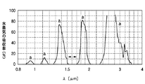
次に、本発明の実施の形態の加熱調理器の内部構造の一例を説明する。図2に、本発明の実施の形態の加熱調理器を左右(加熱調理器の前面部に向かって左右方向)に切断した断面図を、図3に、本発明の実施の形態の加熱調理器の天面の天板を天面方向に切断した断面図を、図4に、光の波長に対する水蒸気の光を吸収する割合を示すグラフを、図5に、本発明の実施の形態の加熱調理器を前後(加熱調理器の前面部から加熱室の奥に向かう方向)に切断した断面図を、それぞれ示す。 Next, an example of the internal structure of the heating cooker according to the embodiment of the present invention will be described. FIG. 2 is a cross-sectional view of the heating cooker according to the embodiment of the present invention cut left and right (left and right direction toward the front portion of the heating cooker), and FIG. 3 is a heating cooker according to the embodiment of the present invention. FIG. 4 is a cross-sectional view of the top plate of the top surface cut in the top surface direction, FIG. 4 is a graph showing the ratio of absorbing water vapor to the wavelength of light, and FIG. Sectional drawing which cut | disconnected the cooker in the front and back (direction which goes to the back of a heating chamber from the front part of a heating cooker) is shown, respectively.
図2および図3に示すように、本発明の実施の形態の加熱調理器100は、加熱室11と、蒸気を透過し易い赤外線を発生させる赤外線発生手段20と、係止部17に支持されて加熱室11を上下に区画する加熱皿30と、被加熱物12aである食品を置く加熱室11の底面兼載置台11aよりも下側から高周波を供給する高周波発生手段40と、加熱室11内に蒸気を発生させる蒸気発生手段60と、を備えている。なお、本実施の形態では、蒸気発生手段60を加熱室11内に設けたが、加熱室11外で発生させた蒸気を加熱室11内に供給してもよい。
As shown in FIGS. 2 and 3, the
蒸気発生手段60によって、蒸気は次々に供給されて加熱室内を循環するので、被加熱物12aに接する領域の蒸気密度がゼロになるわけではなく、被加熱物12aの表面が過度に焦げるのを防止することができる。また、蒸気は、加熱皿30によって区画された空間のうちの上の空間にも循環するため(蒸気のこの循環は加熱皿30の構造によって実現される。加熱皿30の構造については後述する。)、加熱皿30に載置された被加熱物12bの内部の温度上昇を促し中心部に生が残ることなく過度に焦げることを防止することができる。また、表面に適度な湿度を与えることになるので被加熱物12bの表面を蒸気で包むことになり、被加熱物12bの内部の水分が逃げにくくなり、表面はカリッと焼かれ、中身はジューシーな調理を行うことができることになる。
Since the steam is supplied one after another by the steam generating means 60 and circulates in the heating chamber, the steam density in the region in contact with the object to be heated 12a does not become zero, and the surface of the object to be heated 12a is excessively burnt. Can be prevented. Further, since the steam circulates also in a space above the space partitioned by the heating dish 30 (this circulation of the steam is realized by the structure of the
この加熱調理器100は、二つのアンテナを回転させる方式を用いた電子レンジであり、被加熱物12aである食品を置く加熱室11の底面兼載置台11aよりも下側から高周波を供給する高周波発生手段40を有しており、高周波発生手段40であるマグネトロン41を右側に設けた例である。マグネトロン41から発生した高周波を加熱室11内に導く導波管42と、電波を加熱室11へ放射する回転アンテナ43を設けている。回転アンテナ43は、放射指向性を有する構成である。本実施の形態の加熱調理器100は、回転アンテナ43のうちの少なくとも一方の放射指向性の強い部位を所定の向きに制御して特定の方向にマイクロ波をより集中して放射する構成としている。図5に示す加熱室11の底面兼載置台11aから天面方向に伸びる矢印は、回転アンテナ43から放射されるマイクロ波を表しており、その向きはマイクロ波が放射される方向を、その長さはマイクロ波の強度を示している。図5では、加熱皿の周部付近にマイクロ波が強く放射される場合を示している。具体的にどのように制御しているかについては後述する。
This
また、図5に示すように、加熱室11の奥の仕切板11cの後方には、連通路14と循環ファン15とヒータ16を有しており、循環ファン15によって加熱室11内の空気を吸い込んでヒータ16により加熱し(図5における加熱室11から循環ファン15に向かう矢印がその空気の流れを表している。)、仕切板11cに設けられている排出孔から加熱された空気を加熱室11内に送ることができるようになっている(図5におけるヒータ16から加熱室11に向かう矢印がその空気の流れを表している。)。
Further, as shown in FIG. 5, a
また、図2及び図5に示すように、加熱室11上部には、赤外線発生手段20として赤外線を発生させる複数本(図3に示すように、天井面11bの中央にアルゴンヒータ21a、そのアルゴンヒータ21aの前後両側にミラクロンヒータ21b、の合計3本が設けられている。)の管ヒータ21(光ヒータ)を備えており、この各管ヒータ21と、マグネトロン41を制御部で制御し、管ヒータ21が水蒸気に吸収されにくい波長の赤外線を輻射して、加熱室11内に存在する水蒸気を透過して被加熱物12b(加熱皿30がない場合は被加熱物12a)に当てて調理を行う構成としている。なお、アルゴンヒータ21aおよびミラクロンヒータ21bを総称する場合には、管ヒータ21と記すことにする。
As shown in FIGS. 2 and 5, the
複数の波長を発生する管ヒータ21はそれが発生する赤外線の波長が、図4に示すように水蒸気吸収率が低い領域の波長である1.5μm以上1.7μm未満もしくは、2.0μm以上2.3μm未満もしくは、3.4μm以上4.5μm未満のいずれか一つの波長をピークとして発生するように構成してある。
As shown in FIG. 4, the
これによって3本の管ヒータ21からは水蒸気吸収率が低い領域の波長である1.5μm以上1.7μm未満もしくは、2.0μm以上2.3μm未満もしくは、3.4μm以上4.5μm未満のいずれか一つの波長をピークとする赤外線が加熱室11内に放射され、この赤外線が水蒸気に吸収されることなくこれを透過して被加熱物12a、12bである食品を効率よく輻射加熱することになる。
As a result, the wavelength of the region where the water vapor absorption rate is low is from 1.5 μm to less than 1.7 μm, from 2.0 μm to less than 2.3 μm, or from 3.4 μm to less than 4.5 μm. Infrared light having a peak at one wavelength is radiated into the
その結果、加熱室11に置かれた被加熱物12b(12a)を直接より素早く均一に加熱できる。また、赤外線が被加熱物12b(12a)表面に直接輻射されるようになると被加熱物12b(12a)表面がパリッと仕上がり焦げ目も素早く付けることが可能となる。さらに、蒸気は循環して次々に供給されるので、被加熱物12a、12bに接する領域の蒸気密度がゼロになるわけではなく、被加熱物12a、12bの内部の温度上昇を促しつつ表面が過度に焦げるのを防止することができる。また、被加熱物12b(12a)の表面を蒸気で包むことになるので、被加熱物12b(12a)の内部の水分が逃げにくくなり、表面はカリッと焼かれ、中身はジューシーな調理を行うことができることになる。
As a result, the object to be heated 12b (12a) placed in the
図5に示すように、加熱室11の天井面11bに管ヒータ21は、天井面11bの中央にアルゴンヒータ21aが設けられ、そのアルゴンヒータ21aの前後両側にミラクロンヒータ21bが設けられていて、前述したような所望の波長の赤外線を発生させている。アルゴンヒータ21aは心線がタングステン線であり、透明な管部材22にはアルゴンガスが封入されている。このアルゴンヒータ21aは、ミラクロンヒータ21bと比較して動作の立ち上がりが早いという特徴を持っている。
As shown in FIG. 5, the
ミラクロンヒータ21bは、従来から用いられているが、アルゴンヒータ21aより波長が長く、マイカヒータなどに比較して立ち上がりが早いので、被加熱物12a、12bの表面に焦げ色を付けるのに適している。また、コストが安いという特徴がある。
The
ここで、ミラクロンヒータ21bを電子レンジに搭載する場合、ミラクロンヒータ21bがマイクロ波を吸収し発熱してしまい、使用しているガラス材料を溶かす恐れがあるので、誘電率が比較的低くマイクロ波を吸収しにくい、白色管のミラクロンヒータ21bを採用することが望ましい。
Here, when the
また、加熱室11には、図2及び図5に示すように、加熱室11における互いに対向する立壁11d、11dに係止部17が設けられている。加熱皿30は、この係止部17に支持されて加熱室11を上下に区画するとともに被加熱物12bを載置することができる。なお、加熱皿30によって区画される下の空間を第1の空間、上の空間を第2の空間と称することがある。
Moreover, as shown in FIG.2 and FIG.5, the latching | locking
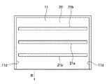
加熱皿30は、図6の本発明の実施の形態の加熱調理器における加熱皿の構成図に示すように、全体矩形板状の加熱皿30の左右両辺には樹脂取っ手33が設けられており、加熱室11の係止部17に沿って前後方向へ出し入れ可能となっている。また、加熱皿30の周部には、加熱室11を上下に連通する連通孔31が設けられている。これにより、加熱皿30によって区画した加熱室11の下方において蒸気を発生させ、発生した蒸気を加熱皿30の周部に設けた連通孔31から上方に案内して、加熱皿30の上に載置された被加熱物12bを加熱調理する。図5において、加熱皿30によって区画される下の空間から加熱皿30の周部を通過して加熱皿30によって区画される上の空間に向かう矢印があるが、この矢印が、上の空間に向かう蒸気の流れを表している。
As shown in the configuration diagram of the heating dish in the heating cooker according to the embodiment of the present invention in FIG. 6, the
また、加熱室11の第1の空間に放射されたマイクロ波の一部は、加熱皿30の周部を通過して第2の空間に伝播する。加熱皿30のうち、係止部17に接する樹脂取っ手33以外の箇所は、加熱室11の壁面に接しておらず、当該箇所からマイクロ波が第2の空間に伝播し易い。加熱皿30に設けられた連通孔31もまた、第1の空間から第2の空間へのマイクロ波の伝播を助長する。その結果、第2の空間に伝播したマイクロ波によって、加熱皿30に載置された被加熱物12bが加熱される。特に、図5に示すように、回転アンテナ43のマイクロ波の放射指向性の強い方向を加熱皿30の周部に向けると、回転アンテナ43から放射されたマイクロ波が減衰を最小限に留められた状態で第2の空間にも伝播することになり、加熱皿30に載置された被加熱物12bを効率的に加熱することができる。
In addition, a part of the microwave radiated to the first space of the
また、加熱皿30の底面兼載置台には、高周波発生手段40によって発せられる高周波を吸収して発熱する例えばフェライトゴムのような電波吸収発熱体32を設けるのが望ましい。これにより、加熱皿30の上に載置された被加熱物12bを下側から加熱することになり、被加熱物12bを上下両面から加熱調理することができる。なお、電波吸収発熱体32に接する加熱皿30の下面を未塗装とすることにより、熱伝導率が向上し、調理時間を短縮することができる。さらに、回転アンテナ43のマイクロ波の放射指向性の強い方向を加熱皿30に向ければ、加熱皿30を効率的に昇温させることができる。
In addition, it is desirable to provide a radio wave
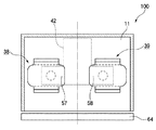
続いて、回転アンテナの具体的な構成、及び回転アンテナの制御方法について説明する。図7に、本発明の実施の形態の加熱調理器における、回転アンテナ付近の詳細な構成図(正面から見た断面図)を、図8に、図7のB−B’における加熱調理器の断面図を、それぞれ示す。 Next, a specific configuration of the rotating antenna and a method for controlling the rotating antenna will be described. FIG. 7 is a detailed configuration diagram (cross-sectional view seen from the front) in the vicinity of the rotating antenna in the heating cooker according to the embodiment of the present invention. FIG. 8 is a diagram of the heating cooker in BB ′ of FIG. Cross-sectional views are shown respectively.
図7に示すように、加熱調理器100は、代表的なマイクロ波発生手段であるマグネトロン41から放射されたマイクロ波を伝送する導波管42と、導波管42の上部に接続され幅方向寸法(約410mm)が奥行き方向寸法(約315mm)より大きい形状の加熱室11と、代表的な被加熱物である食品(図示せず)を載置するため加熱室11内に固定され、セラミックやガラスなどの低損失誘電材料からなるためにマイクロ波が容易に透過できる性質の載置台11aと、加熱室11内の載置台11aより下方に形成されるアンテナ空間37と、導波管42内のマイクロ波を加熱室11内に放射するため、導波管42からアンテナ空間37にわたり、加熱室11の幅方向に対して対称位置に取り付けられた二つの回転アンテナ38、39と、回転アンテナ38、39を回転駆動できる代表的な駆動手段としてのモータ61、62と、モータ61、62を制御して回転アンテナ38、39の向きを制御する制御部160(後述する図17に記載。)と、各回転アンテナ38、39の回転の原点を検出する原点検出機構を構成するフォトインタラプタ36と、加熱室11内の温度分布を検出する温度分布検出手段である赤外線センサ10と、を有する。
As shown in FIG. 7, the
また、回転アンテナ38、39は、導波管42と加熱室底面兼載置台との境界面に設けられた直径約30mmで略円形の結合孔43、44を貫通する直径約18mmで略円筒状の導電性材料から成る結合部45、46と、結合部45、46の上端にかしめや溶接などで電気的に接続されて一体化され、概ね垂直方向よりも水平方向に広い面積を有する導電性材料から成る放射部47、48とを備える。
The
また、回転アンテナ38,39は、結合孔43、44の中心が回転駆動の中心となるようにモータ61、62のシャフト49、50に嵌合された構成としている。放射部47、48は回転の方向に対して形状が一定ではないために放射指向性がある構成としている。
The
回転アンテナ38、39の回転の中心は加熱室11内の中心から略等距離に配置する。この構成により、アンテナが一つの構成では通常は加熱しにくい加熱室内の中央付近を、回転アンテナ38、39の放射指向性の強い部分を中央付近に向けることにより加熱可能とするものである。
The centers of rotation of the
放射部47、48は同一の形状で、放射部上面51、52が略四辺形にRを有する形状で、そのうち対向する2辺には加熱室底面兼載置台側に曲げられた放射部曲げ部53、54を有し、その2辺の外側へのマイクロ波の放射を制限する構成である。加熱室底面兼載置台と放射部上面51、52までの距離は約10mm程度とし、放射部曲げ部53、54は、それよりも約5mm程度低い位置に引き下げられている。
The radiating
そして、残る2辺は結合部45、46から端部までの水平方向の長さが異なり、結合部の中心からの長さが75mm程度の端部55、56、結合部の中心からの長さが55mm程度の端部57、58を構成している。また端部の幅方向の寸法はいずれも80mm以上としている。この構成において回転アンテナ38、39は、結合部45、46から端部57、58の方向への放射指向性を強くすることができる。
The remaining two sides have different horizontal lengths from the
この構成において一般的な食品を均一に加熱する場合は、従来の電子レンジと同様、特に置き場所にこだわる必要はなく、回転アンテナ38、39も従来同様に一定回転させてよい。一方、集中加熱する場合、例えば加熱室11内の中央付近を加熱する場合、制御部160は、図9の本発明の実施の形態の加熱調理器による回転アンテナの向きの一例に示すように、回転アンテナ38、39の端部57、58を、加熱室11の幅方向の略中央かつ奥行き方向の略中央という所定の向きに向けるように制御する。
In the case of heating a general food uniformly in this configuration, it is not necessary to pay particular attention to the place of placement as in the case of a conventional microwave oven, and the
回転アンテナ38、39の端部57、58が加熱室11の幅方向の略中央かつ奥行き方向の略中央を向くとき、端部57、58の方向への放射指向性が強いので、特に端部57、58の方向からマイクロ波が放射されその方向に位置する食品を集中的に加熱することができる。
When the
また、加熱室11内の左側付近を加熱する場合、制御部160は、図10の本発明の実施の形態の加熱調理器による回転アンテナの向きの一例に示すように、回転アンテナ38、39の端部57、58を、左向き(加熱室11をドア64側から見て左側)に向けるように制御する。
Further, when the vicinity of the left side in the
同様に、加熱室11内の右側付近を加熱する場合、制御部160は、図11の本発明の実施の形態の加熱調理器による回転アンテナの向きの一例に示すように、回転アンテナ38、39の端部57、58を、右向き(加熱室11をドア64側から見て右側)に向けるように制御する。
Similarly, when the vicinity of the right side in the
また、加熱室11内の前方中央付近を加熱する場合、制御部160は、図12の本発明の実施の形態の加熱調理器による回転アンテナの向きの一例に示すように、回転アンテナ38、39の端部57、58を、加熱室11の幅方向の略中央かつ奥行き方向の前方(加熱室11内の中央前方付近)に向けるように制御する。
In addition, when the vicinity of the front center in the
また、加熱室11内の後方中央付近を加熱する場合、制御部160は、図13の本発明の実施の形態の加熱調理器による回転アンテナの向きの一例に示すように、回転アンテナ38、39の端部57、58を、加熱室11の幅方向の略中央かつ奥行き方向の後方(加熱室11内の中央後方付近)に向けるように制御する。
In addition, when the vicinity of the rear center in the
以上のように、本実施の形態の加熱調理器100は、局所的に加熱したい場所に応じて回転アンテナの向きを制御するものであり。回転アンテナ38、39を所定の向きに向けるためには、モータ61、62としてステッピングモータを用いるとか、あるいは一定回転のモータであっても基準位置を検出して通電時間を制御するなどの手段が考えられる。
As mentioned above, the
本実施の形態の加熱調理器では、モータ61、62としてステッピングモータを用いており、各モータのシャフト49、50にそれぞれ原点検出機構を設けている。図14に、図7のD−D’における加熱調理器の断面図を示す。原点検出機構は、図14に示すように、シャフトを中心軸とする円板36aと、フォトインタラプタ36とにより構成される。円板36aには、矩形状のスリット36bが設けられている。
In the cooking device of the present embodiment, stepping motors are used as the
円板36aは、回転アンテナ38、39を回転させるモータのシャフト49、50の軸にそれぞれ共通に取り付けられていて、発光素子と受光素子とを備えたフォトインタラプタ36の光路を遮るように回転するものである。
The
この構成により、スリット36bがフォトインタラプタ36の光路を通過するときは、前記光路を遮るものが無いので、スリットの通過時点を検出することができる。従って、スリット36bの位置を回転アンテナ38、39の原点と設定しておくことで、各モータに取り付けられたフォトインタラプタ36により回転アンテナの原点を検出することができるものである。
With this configuration, when the
また、制御部は、原点検出機構で検出できる原点を基準として、回転アンテナ38、39の指向性の強い部分を局所加熱箇所に集中させるときの回転アンテナ38、39の角度(停止位置)を予め記憶しているアンテナ角度記憶部を有している。回転アンテナ38、39の動作を制御して局所加熱を実行する際には、アンテナ角度記憶部の情報が参照される。
In addition, the control unit determines in advance the angle (stop position) of the
次に、図15に示す、本発明の実施の形態の加熱調理器における赤外線センサ10の構成図を参照して、本実施の形態の加熱調理器が備える温度検出手段について説明する。この温度検出手段は、基板109上に一列に並んで設けられた複数の赤外線検出素子103と、基板109全体を収納するケース108と、ケース108を赤外線検出素子103が並んでいる方向と垂直に交わる方向に移動させるステッピングモータ101と、を備えるものである。
Next, with reference to the block diagram of the
基板109上には、赤外線検出素子103を封入する金属製のカン105と、赤外線検出素子の動作を処理する電子回路110とが設けられている。また、カン105には赤外線が通過するレンズ104が設けられている。また、ケース108には、赤外線を通過させる赤外線通過孔106と、電子回路110からのリード線を通過させる孔107とが設けられている。
On the
この構成により、ステッピングモータ101が回転運動することで、ケース108を、赤外線検出素子103が一列に並んでいる方向とは垂直方向に移動させることができる。
With this configuration, when the stepping
図16は、図7のC−C’断面における赤外線温度検出スポットを説明する図であり、図17は、本発明の実施の形態における赤外線温度検出スポットを説明するための加熱調理器の断面図(正面図)である。図17に示すように、本実施の形態の加熱調理器100は、制御部160による制御のもと、温度検出手段のステッピングモータ101が往復回転動作することにより、加熱室11内のほぼ全ての領域の温度分布を検出することができるものである。
16 is a diagram for explaining infrared temperature detection spots in the CC ′ section of FIG. 7, and FIG. 17 is a sectional view of a heating cooker for explaining infrared temperature detection spots in the embodiment of the present invention. (Front view). As shown in FIG. 17, the
具体的には、例えば、まず図16中のA1〜A4の領域の温度分布を、温度検出手段が有する一列に並んだ温度検出素子103(例えば、赤外線センサ)が同時に検出する。次に、ステッピングモータ101が回転動作しケース108が移動するとき、温度検出素子103がB1〜B4の領域の温度分布を検出する。さらに、ステッピングモータ101が回転動作してケース108が移動するとき、温度検出素子103がC1〜C4の領域の温度分布を検出し、同様に、D1〜D4の領域の温度分布が検出される。
Specifically, for example, first, the temperature detection elements 103 (for example, infrared sensors) arranged in a line of the temperature detection unit simultaneously detect the temperature distribution in the areas A1 to A4 in FIG. Next, when the stepping
また、上述の動作に続けて、ステッピングモータ101が逆回転することで、D1〜D4の領域側から、C1〜C4、B1〜B4、A1〜A4の順に、温度分布を検出する。温度分布検出手段は、以上の動作を繰り返すことで、加熱室11内の全体の温度分布を検出することができる。
Further, following the above-described operation, the stepping
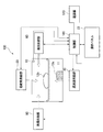
続いて、本発明の参考例の加熱調理器による、マイクロ波により加熱処理時における一連の処理を説明する。図18に、本発明の参考例の加熱調理器の構成を示す機能ブロック図を示す。 Subsequently, a series of processes at the time of heat treatment by microwaves by the cooking device of the reference example of the present invention will be described. In FIG. 18, the functional block diagram which shows the structure of the heating cooker of the reference example of this invention is shown.
加熱調理器100は、高周波発生部40(図2における、マグネトロン41、導波管42、及び回転アンテナ43により構成される。)と、熱風供給部80(図5における、連通路14、循環ファン15、及びヒータ16により構成される。)と、輻射熱供給部20(図3における管ヒータ21に相当する。)と、蒸気供給部60(図2における蒸気発生手段60に相当する。)と、操作パネル23(図1における操作パネル23に相当する。)と、赤外線センサ10(図7における赤外線センサ10に相当する。)と、電源部170と、加熱調理器100全体を制御する制御部160とを備えている。
The
制御部160は、図示しないCPU(Central Processing Unit)とROM(Read Only Memory)とを備えている。CPUは、ROMに格納されているプログラム及びデータに従って制御を行う。制御部160による制御には、高周波発生部40、熱風供給部80、輻射熱供給部20、蒸気供給部60のいずれか一つまたは複数へ電源部170からの給電量を優先して確保する制御が含まれる。この制御により、高周波発生部40、熱風供給部80、輻射熱供給部20、蒸気供給部60のいずれか一つまたは複数が駆動し、被加熱物12a、12bを加熱する。
The
次に、本発明の参考例の加熱調理器による処理の流れを説明する。図19に、本発明の参考例の加熱調理器による加熱処理のフローチャートを示す。 Next, the flow of the process by the heating cooker of the reference example of this invention is demonstrated . In FIG. 19, the flowchart of the heat processing by the heating cooker of the reference example of this invention is shown.
まず、制御部は、操作パネルによって、上下加熱調理のための操作、特に、被加熱物の状態を通知する操作、加熱処理に対する条件を指示する操作、及び加熱処理の開始を指示する操作を受け付ける(ステップ101)。被加熱物の状態を通知する操作には、被加熱物の重量、形状、個数、などを入力する操作が含まれる。この操作は、利用者が被加熱物の重量、形状、個数を測定し、その測定した数値を入力する構成でもよいが、好ましくは、加熱調理器に付随するレシピブックに記述されているあるレシピの識別番号を操作パネルのダイヤルにて指定する。このレシピブックには、レシピ毎に、調理に必要な素材のグラム数、個数、大きさなどが取り決められているため、制御部は、レシピの識別番号を指示する操作を受け付けることによって、被加熱物の状態を認識することができる。なお、本発明の参考例の被加熱物の状態を通知する操作は、必須ではなく、加熱室内に設けられた各種センサ(図示せず)によって被加熱物の重量、形状、個数を測定し、その測定した数値を入力値とする構成であってもよい。 First, the control unit accepts an operation for cooking up and down, particularly an operation for notifying a state of an object to be heated, an operation for instructing a condition for the heat treatment, and an operation for instructing the start of the heat treatment by the operation panel. (Step 101). The operation for notifying the state of the object to be heated includes an operation for inputting the weight, shape, number, etc. of the object to be heated. This operation may be configured such that the user measures the weight, shape, and number of objects to be heated and inputs the measured numerical values. Preferably, a recipe described in a recipe book attached to the heating cooker is used. The identification number is specified with the dial on the operation panel. In this recipe book, the number of grams, the number, the size, etc. of the ingredients necessary for cooking are determined for each recipe. Therefore, the control unit accepts an operation to instruct the recipe identification number, The state of the object can be recognized. The operation of notifying the state of the object to be heated in the reference example of the present invention is not essential, and the weight, shape, and number of objects to be heated are measured by various sensors (not shown) provided in the heating chamber. The measured numerical value may be used as an input value.
また、加熱処理に対する条件としては、主に、被加熱物を載置する場所、場所毎の被加熱物に対する加熱方法、が挙げられる。被加熱物を載置する場所は、具体的には、1.加熱室の底面兼載置台のみ、2.加熱皿のみ、あるいは、3.加熱室の底面兼載置台及び加熱皿、を指示する条件である。
The conditions for the heat treatment mainly include a place where the object to be heated is placed and a heating method for the object to be heated at each place. Specifically, the place to place the object to be heated is: 1. Only the bottom and mounting table of the
また、場所毎の被加熱物に対する加熱方法には、加熱室の底面兼載置台に載置された被加熱物、及び加熱皿に載置された被加熱物に対する加熱方法(高周波による加熱、熱風による加熱、輻射熱による加熱、蒸気による加熱、各加熱方法による加熱温度、各加熱方法による加熱時間など)を指示する条件である。これらの条件は、利用者が操作パネルによって入力する構成でもよいが、好ましくは、レシピの識別番号を指示する操作を受け付けることによって、当該レシピの識別番号毎に規定されている、各加熱方法の順序、加熱温度及び加熱時間などを参照する。 In addition, the heating method for the object to be heated at each location includes a heating object placed on the bottom and mounting table of the heating chamber and a heating method for the object to be heated placed on the heating pan (high-frequency heating, hot air Heating by radiant heat, heating by steam, heating temperature by each heating method, heating time by each heating method, etc.). These conditions may be configured to be input by the user through the operation panel, but preferably, by accepting an operation for instructing the recipe identification number, each heating method defined for each recipe identification number is accepted. Refer to the order, heating temperature and heating time.
本発明の参考例では、被加熱物は、3.加熱室の底面兼載置台及び加熱皿に載置され、加熱室の底面兼載置台にはマイクロ波による加熱を要する被加熱物を、加熱皿には輻射熱による加熱を要する被加熱物を、それぞれ載置する場合を説明する。その他の加熱方法は従来からよく知られているものと同じであり、説明は省略する。 In the reference example of the present invention, the object to be heated is 3. Placed on the bottom and mounting table and heating pan of the heating chamber, the heated object that needs to be heated by microwaves on the bottom and mounting table of the heating chamber, and the heated object that requires heating by radiant heat on the heating plate, respectively The case of mounting will be described. Other heating methods are the same as those well known in the art, and a description thereof will be omitted.
制御部は、操作パネルによって受け付けた被加熱物の状態を通知する操作によって検出した被加熱物の状態(場合によっては加熱室内に設けられた各種センサによって検出させてもよい)を基に、マイクロ波によって加熱しようとする加熱室の底面兼載置台に載置された被加熱物の負荷量を特定する(ステップ102)。具体的には、制御部は、被加熱物の重量、形状、個数と、その重量、形状、個数を有する被加熱物の負荷量と、を対応付けたテーブルをROMに記憶しており、そのテーブルを参照して、操作パネルによって受け付けた、または各種センサによって検出した加熱物の状態に対応する負荷量を特定する。なお、制御部は、レシピや操作部に記載されている識別番号を指示する操作を受け付けることによって被加熱物の状態を通知される場合がある。この場合にも同様に、各レシピや操作部に記載されている識別番号と、そのレシピに必要とされる被加熱物の負荷量と、を対応付けたテーブルをROMに記憶しておき、そのテーブルを参照して、操作パネルによって受け付けたレシピの識別番号に対応する負荷量を特定する。 Based on the state of the heated object detected by the operation for notifying the state of the heated object received by the operation panel (may be detected by various sensors provided in the heating chamber in some cases), The load amount of the object to be heated placed on the bottom / mounting table of the heating chamber to be heated by the wave is specified (step 102). Specifically, the control unit stores in the ROM a table that associates the weight, shape, and number of the object to be heated with the load amount of the object to be heated having the weight, shape, and number. The load amount corresponding to the state of the heated object received by the operation panel or detected by various sensors is specified with reference to the table. Note that the control unit may be notified of the state of the object to be heated by receiving an operation for instructing the identification number described in the recipe or the operation unit. In this case as well, a table in which the identification number written in each recipe or operation unit and the load amount of the heated object required for the recipe are stored in the ROM is stored. With reference to the table, the load amount corresponding to the identification number of the recipe received by the operation panel is specified.
制御部は、被加熱物の負荷量を特定すると、その負荷量の大小を判定し(ステップ103)、回転アンテナ38、39の端部57、58を向けるべき方向を決定し、回転アンテナ38、39を決定した方向に回転する。制御部は、加熱室の底面兼載置台に載置された被加熱物の負荷量が大きいほど(ステップ104、Y)、回転アンテナ38、39の端部57、58を向けるべき方向を被加熱物が載置される加熱室中央から分散させ加熱皿に集中させる(ステップ105)、被加熱物の負荷量が小さいほど(ステップ104、N)、回転アンテナ38、39の端部57、58を向けるべき方向を加熱室中央に集中させる(ステップ106)。
When the control unit specifies the load amount of the object to be heated, it determines the magnitude of the load amount (step 103), determines the direction in which the
なお、マイクロ波による加熱時、蒸気供給部60からスチームを供給して、加熱室の底面兼載置台に載置された被加熱物または加熱皿に載置された被加熱物を併用加熱するようにしてもよい。これにより、被加熱物の表面にうるおいをもたした状態で被加熱物を加熱することができる。
During heating by microwaves, steam is supplied from the
この処理によって、加熱室の底面兼載置台11aに載置された第1の被加熱物の負荷量が大きい場合には回転アンテナ38、39の放射指向性の強い部位が被加熱物に向けられないことになるが、回転アンテナ38、39の放射指向性のそれほど強くない部位は被加熱物に向けられており負荷量が大きいため、その部位から放射されたマイクロ波は効率よく吸収され当該被加熱物を充分加熱することができる。他方、回転アンテナ38、39の放射指向性の強い部位が向けられた方向には被加熱物が存在しておらず、従って、回転アンテナ38、39から放射されるマイクロ波は、最小限の減衰をもって加熱皿30に到達し加熱皿を昇温させることができる、さらには、最小限の減衰をもって加熱皿30の周部を通過し加熱皿30に載置された被加熱物12bを加熱することができる。
By this process, when the load amount of the first object to be heated placed on the bottom surface / mounting table 11a of the heating chamber is large, the parts having strong radiation directivity of the
制御部は、回転アンテナ38、39を回転させた後高周波供給部40に給電してマイクロ波の放射を開始させる(ステップ107)。その後、制御部が特定した、ある第1、第2の被加熱物の組み合わせの中での第1所定の時間(これは特定された第1、第2の被加熱物の組み合わせ毎にその組み合わせの中での第1、第2の被加熱物の重量、形状、個数等によって予め記憶されている)になるまで(ステップ108、Y)、上記の回転アンテナ38、39によるマイクロ波の放射を継続する。これによって第1の被加熱物が主体的に加熱されるとともに、加熱皿30及び当該加熱皿上の第2の被加熱物が予備加熱される。
The control unit rotates the
制御部は、第1の所定時間に達したと判断すると(ステップ108、Y)、加熱皿30に載置された被加熱物を加熱するために輻射熱供給部20に給電して輻射熱による加熱を開始させる(ステップ109)。その後、時間が経過して予め定めた第2所定の時間(これも特定された第1、第2の被加熱物の組み合わせ毎にその組み合わせの中での第1、第2の被加熱物の重量、形状、個数等によって予め記憶されており、第1の被加熱物の加熱が完了する時間である)になると(ステップ110、Y)、輻射熱による加熱を停止する(ステップ111)。
When the control unit determines that the first predetermined time has been reached (
このように、この加熱調理器では、加熱室の底面兼載置台11aに載置された第1の被加熱物の負荷量が大きい場合においても、輻射熱による加熱を開始するときには既に加熱皿30の温度は負荷量が小さいときに比べ若干低いものの充分昇温されており、さらに、加熱皿30に載置された被加熱物もマイクロ波による照射によって予熱されているため、第一の加熱物と第二の加熱物を別々に加熱した場合の加熱時間の合計と比べて両者を同時期に加熱した場合の方が加熱時間を短縮することができる。
Thus, in this heating cooker, even when the load amount of the first object to be heated placed on the bottom surface / mounting table 11a of the heating chamber is large, when the heating by radiant heat is started, the
また、加熱室の底面兼載置台に載置された被加熱物の負荷量が小さい場合にも、輻射熱による加熱を開始するときには、従来のように、加熱皿にのみ被加熱物を載置して輻射熱による被加熱物の加熱とマイクロ波による加熱皿の昇温とを同時期に開始する場合と比べれば、加熱皿30は充分加熱されていると言え、第一の加熱物と第二の加熱物を別々に加熱した場合の加熱時間の合計と比べて両者を同時期に加熱した場合の方が加熱時間を短縮することができる。
In addition, even when the load of the object to be heated placed on the bottom / mounting table of the heating chamber is small, when heating by radiant heat is started, the object to be heated is placed only on the heating pan as in the past. Compared to the case where the heating of the object to be heated by radiant heat and the heating of the heating dish by microwave are started at the same time, it can be said that the
制御部は、上記の回転アンテナ38、39によるマイクロ波の放射を停止した後、輻射熱による加熱を所定の時間、継続する(ステップ112)。なお、この所定の時間も特定された第1、第2の被加熱物の組み合わせ毎にその組み合わせの中での第1、第2の被加熱物の重量、形状、個数等に応じて第2の被加熱物の加熱が完了する時間で、あらかじめ記憶されており、レシピの識別番号を指示する操作を受け付けたときに参照した加熱時間によって、特定されるが、加熱調理器による調理開始前に使用者が操作パネルによって入力された加熱時間で特定されるようにしてもよい。
After stopping the microwave radiation by the rotating
なお、加熱時、蒸気供給部60からスチームを供給して、加熱室の底面兼載置台に載置された被加熱物または加熱皿に載置された被加熱物を併用加熱するようにしてもよい。これにより、被加熱物の表面にうるおいをもたした状態で被加熱物を加熱することができる。さらに、加熱皿に載置された被加熱物に対してグリル調理やオーブン調理を行う場合が考えられる。グリル調理を行う場合にはスチームによる加熱を併用することで、表面が過度に焦げるのを防止しつつ被加熱物の中身をジューシーに仕上げることができる。一方、オーブン調理の場合スチームを併用することで内部の火通りを良くし、被加熱物の表面をパリッと、中身をジューシーに仕上げることができる。
In addition, at the time of heating, steam may be supplied from the
そして、制御部は、輻射熱による加熱を所定の時間継続すると(ステップ112、Y)、輻射熱による加熱を停止し(ステップ113)、一連の加熱処理を停止する。
Then, when heating by radiant heat is continued for a predetermined time (
以上、従来の加熱調理器では、加熱室の底面兼載置台に被加熱物が載置されている場合には、加熱皿を充分昇温させることができなかったが、本発明の参考例の加熱調理器によれば、加熱室の底面兼載置台に被加熱物が載置されている場合にも、効果的に加熱皿を昇温させることができる。さらに、輻射熱による加熱の対象となる、加熱皿に載置されている被加熱物を輻射熱による加熱前にマイクロ波によって加熱しておくことができる。このことは、加熱室の底面兼載置台と加熱皿とにそれぞれ別の被加熱物を載置した状態で加熱処理を開始し完了させるという、これまでの加熱調理器にはなかった新たな調理方法、すなわち加熱皿によって区切られる上下の空間を一度の処理によって加熱するという上下加熱を提案することに通ずる。 As described above, in the conventional cooking device, when the object to be heated is placed on the bottom / mounting table of the heating chamber, the heating dish could not be sufficiently heated, but in the reference example of the present invention , According to the heating cooker, even when an object to be heated is placed on the bottom / mounting table of the heating chamber, the temperature of the heating dish can be increased effectively. Furthermore, the object to be heated, which is a target for heating by radiant heat, placed on a heating pan can be heated by microwaves before being heated by radiant heat. This is a new cooking that has not been done in previous cooking devices, in which heating processing is started and completed in a state where different objects to be heated are placed on the bottom surface of the heating chamber and the heating pan, respectively. This leads to the proposal of the method, that is, the upper and lower heating in which the upper and lower spaces separated by the heating pan are heated by a single treatment.
また、加熱室の底面兼載置台に載置される被加熱物の形状、重さ、個数などの状態に応じて回転アンテナの向きを制御することによって、加熱室の底面兼載置台に載置される被加熱物へのマイクロ波の放射、または、加熱皿または加熱皿の周部へのマイクロ波の放射、を好適に切り替えることができる。 In addition, the orientation of the rotating antenna is controlled according to the shape, weight, number, etc. of the object to be heated placed on the bottom / mounting table of the heating chamber, thereby placing it on the bottom / mounting table of the heating chamber. The microwave radiation to the object to be heated or the microwave radiation to the heating dish or the peripheral part of the heating dish can be suitably switched.
また、加熱皿に載置された被加熱物を輻射熱によって加熱する前に上述のように加熱皿または加熱皿に載置された被加熱物をマイクロ波によって加熱しておくことによって、第1の加熱物と第2の加熱物を別々に加熱した場合の加熱時間の合計と比べて両者を同時期に加熱した場合の方が時間を短縮することができる。 Further, before heating the object to be heated placed on the heating dish by radiant heat, the heating dish or the object to be heated placed on the heating dish is heated by the microwave as described above, whereby the first Compared with the sum total of the heating time at the time of heating a heating thing and a 2nd heating thing separately, the direction where both are heated at the same period can shorten time.
また、加熱調理器に付随するレシピブックに従って加熱室の底面兼載置台及び加熱皿に適量の被加熱物を載置すれば、レシピを特定する識別情報を入力するだけで上下加熱処理を加熱調理器に行わせることができる。この結果、利用者は、上下加熱に伴う煩雑な入力操作から解放される。 In addition, if an appropriate amount of an object to be heated is placed on the bottom / mounting table and the heating pan of the heating chamber in accordance with the recipe book attached to the heating cooker, the cooking process is performed by simply inputting identification information for identifying the recipe. Can be performed. As a result, the user is relieved from the complicated input operation associated with the vertical heating.
以上、本発明の加熱調理器によれば、加熱室の底面兼載置台に被加熱物を載置した状態でも、マイクロ波によって効果的に加熱皿を昇温させることができ、さらに、加熱皿に載置された被加熱物をマイクロ波によっても効果的に加熱することができる、換言すると加熱室の底面兼載置台と加熱皿の両方に被加熱物を載置して加熱することができるという効果を奏し、被加熱物を誘電加熱する加熱調理器に関する分野において有用である。 As described above, according to the heating cooker of the present invention, even when the object to be heated is placed on the bottom / mounting table of the heating chamber, the heating dish can be effectively heated by the microwave. It is possible to effectively heat the object to be heated placed by the microwave. In other words, the object to be heated can be placed and heated on both the bottom surface mounting table and the heating dish of the heating chamber. It is effective in the field regarding the heating cooker which produces the effect of said and heats to-be-heated material dielectrically.
11 加熱室
11a 加熱室の底面兼載置台
12 食品
20 赤外線発生手段
21 アルゴンヒータ
30 加熱皿
40 高周波発生手段
41 マグネトロン
42 導波管
43 回転アンテナ
DESCRIPTION OF
Claims (7)
前記加熱室内部に着脱自在に設けられ、その上面に第2の被加熱物を載置する着脱自在な加熱皿と、
蒸気を発生し前記加熱室内に供給する蒸気供給手段と、
前記加熱室上部に設けられ、いずれもピーク波長が1.5μm以上1.7μm未満、2.0μm以上2.3μm未満、3.4μm以上4.5μm未満のいずれか1つの赤外線を発生し前記第2の被加熱物を加熱する少なくとも3つの赤外線発生手段と、
マイクロ波を発生する高周波供給手段と、
前記高周波供給手段が発生したマイクロ波を放射するためのアンテナと、
前記被加熱物に対する加熱処理に関する条件を指示する操作を受け付ける操作部と、
前記操作部によって受け付けた、前記第1の被加熱物及び前記第2の被加熱物に対する加熱処理に関する条件を指示する操作に基づいて、前記アンテナの放射指向性の強い部位の向きを制御するとともに前記熱供給手段および前記蒸気供給手段を制御し、前記第1、第2の被加熱物を加熱完了させて運転停止させる制御手段と、を備え、
前記少なくとも3つの赤外線発生手段のうち、中央側に位置する赤外線発生手段が、周囲に位置する赤外線発生手段より短いピーク波長を有する赤外線を発生する加熱調理器。 A heating chamber for mounting the first object to be heated on the bottom surface and mounting table;
A detachable heating pan that is detachably provided in the heating chamber and on which the second object to be heated is placed;
Steam supply means for generating steam and supplying the steam into the heating chamber;
Provided in the upper part of the heating chamber, all generate infrared rays having a peak wavelength of 1.5 μm or more and less than 1.7 μm, 2.0 μm or more and less than 2.3 μm, 3.4 μm or more and less than 4.5 μm. At least three infrared ray generating means for heating two objects to be heated;
High-frequency supply means for generating microwaves;
An antenna for radiating microwaves generated by the high-frequency supply means;
An operation unit for receiving an operation for instructing a condition related to the heat treatment for the object to be heated;
While controlling the direction of a portion having a strong radiation directivity of the antenna based on an operation instructing a condition related to heat treatment for the first heated object and the second heated object received by the operation unit. Control means for controlling the heat supply means and the steam supply means to complete the heating of the first and second objects to be heated and to stop the operation ,
Of the at least three infrared ray generating means, the infrared ray generating means located on the center side generates infrared rays having a shorter peak wavelength than the infrared ray emitting means located around .
前記制御手段は、前記第1の被加熱物に対して加熱処理を行う場合には、前記第1の被加熱物にマイクロ波が放射されるように、前記第2の被加熱物に対して加熱処理を行う場合には、前記第2の被加熱物または前記加熱皿にマイクロ波が放射されるように、前記アンテナの放射指向性の強い部位の向きを制御する加熱調理器。 The cooking device according to claim 1, wherein
When the heat treatment is performed on the first object to be heated, the control unit applies the second object to be heated so that a microwave is emitted to the first object to be heated. A heating cooker that controls the direction of a portion of the antenna having a strong radiation directivity so that microwaves are radiated to the second object to be heated or the heating pan when performing heat treatment.
前記制御手段は、前記第2の被加熱物にマイクロ波を放射する場合、前記加熱皿の周部にマイクロ波が放射されるように、前記アンテナの放射指向性の強い部位の向きを制御する加熱調理器。 A cooking device according to claim 2,
When the microwave is radiated to the second object to be heated, the control means controls a direction of a portion having a strong radiation directivity of the antenna so that the microwave is radiated to a peripheral portion of the heating dish. Cooking cooker.
前記制御手段は、前記アンテナの放射指向性の強い部位の向きを制御して前記第2の被加熱物または前記加熱皿にマイクロ波を放射した後、前記第2の被加熱物を前記熱供給手段によって加熱するよう制御する加熱調理器。 A cooking device according to claim 2 or 3, wherein
The control means controls the direction of a portion having a high radiation directivity of the antenna to radiate microwaves to the second object to be heated or the heating dish, and then supplies the second object to be heated to the heat supply. A cooker that is controlled to heat by means.
前記制御手段は、前記第2の被加熱物に対する加熱処理に関する条件に基づく所定の時間、前記熱供給手段による前記第2の被加熱物の加熱を継続する加熱調理器。 A cooking device according to claim 4, wherein
The said control means is a heating cooker which continues the heating of the said 2nd to-be-heated object by the said heat supply means for the predetermined time based on the conditions regarding the heat processing with respect to the said 2nd to-be-heated object.
前記加熱処理に関する条件には、被加熱物の種類を特定するための識別番号が含まれ、
前記制御手段は、前記操作部によって受け付けた、前記第1の被加熱物及び前記第2の被加熱物を特定するための識別番号に基づいて、前記第1の被加熱物及び前記第2の被加熱物に向けるべき前記アンテナの放射指向性の強い部位の向きを制御する加熱調理器。 A cooking device according to any one of claims 1 to 5,
The conditions relating to the heat treatment include an identification number for specifying the type of the object to be heated,
The control means receives the first heated object and the second heated material based on an identification number for identifying the first heated object and the second heated object received by the operation unit. A heating cooker for controlling the direction of a portion having a strong radiation directivity of the antenna to be directed to an object to be heated.
Priority Applications (5)
| Application Number | Priority Date | Filing Date | Title |
|---|---|---|---|
| JP2007306314A JP4629085B2 (en) | 2007-11-27 | 2007-11-27 | Cooker |
| CN2008801181365A CN101878672A (en) | 2007-11-27 | 2008-11-26 | Cooking device |
| US12/744,980 US20100301039A1 (en) | 2007-11-27 | 2008-11-26 | Cooker |
| EP08854076A EP2217038A1 (en) | 2007-11-27 | 2008-11-26 | Cooking device |
| PCT/JP2008/003482 WO2009069293A1 (en) | 2007-11-27 | 2008-11-26 | Cooking device |
Applications Claiming Priority (1)
| Application Number | Priority Date | Filing Date | Title |
|---|---|---|---|
| JP2007306314A JP4629085B2 (en) | 2007-11-27 | 2007-11-27 | Cooker |
Publications (3)
| Publication Number | Publication Date |
|---|---|
| JP2009129844A JP2009129844A (en) | 2009-06-11 |
| JP2009129844A5 JP2009129844A5 (en) | 2010-03-18 |
| JP4629085B2 true JP4629085B2 (en) | 2011-02-09 |
Family
ID=40678204
Family Applications (1)
| Application Number | Title | Priority Date | Filing Date |
|---|---|---|---|
| JP2007306314A Expired - Fee Related JP4629085B2 (en) | 2007-11-27 | 2007-11-27 | Cooker |
Country Status (5)
| Country | Link |
|---|---|
| US (1) | US20100301039A1 (en) |
| EP (1) | EP2217038A1 (en) |
| JP (1) | JP4629085B2 (en) |
| CN (1) | CN101878672A (en) |
| WO (1) | WO2009069293A1 (en) |
Families Citing this family (7)
| Publication number | Priority date | Publication date | Assignee | Title |
|---|---|---|---|---|
| JP5131969B2 (en) * | 2007-12-19 | 2013-01-30 | パナソニック株式会社 | Cooker |
| JP5471436B2 (en) * | 2009-12-28 | 2014-04-16 | パナソニック株式会社 | Cooker |
| JP5593710B2 (en) * | 2010-01-27 | 2014-09-24 | パナソニック株式会社 | Microwave heating cooker |
| JP5600956B2 (en) * | 2010-02-12 | 2014-10-08 | パナソニック株式会社 | Microwave heating cooker |
| JP5625618B2 (en) * | 2010-08-24 | 2014-11-19 | パナソニック株式会社 | Cooker |
| CN106465490B (en) * | 2014-07-10 | 2019-11-01 | 松下知识产权经营株式会社 | Microwave heating equipment |
| US20190110643A1 (en) * | 2017-10-14 | 2019-04-18 | Gloria Contreras | Smart charger plate |
Citations (8)
| Publication number | Priority date | Publication date | Assignee | Title |
|---|---|---|---|---|
| JP2003257614A (en) * | 2001-12-27 | 2003-09-12 | Sanyo Electric Co Ltd | High frequency heating device |
| JP2004294050A (en) * | 2002-12-12 | 2004-10-21 | Matsushita Electric Ind Co Ltd | High-frequency heating cooker |
| JP2005147604A (en) * | 2003-11-19 | 2005-06-09 | Matsushita Electric Ind Co Ltd | High frequency heating cooking device, and cooking method using the device |
| JP2006097988A (en) * | 2004-09-29 | 2006-04-13 | Sanyo Electric Co Ltd | Microwave oven |
| JP2006286443A (en) * | 2005-04-01 | 2006-10-19 | Matsushita Electric Ind Co Ltd | Microwave heating device |
| JP2007139245A (en) * | 2005-11-16 | 2007-06-07 | Matsushita Electric Ind Co Ltd | High frequency heating cooking apparatus |
| JP2007333362A (en) * | 2006-06-19 | 2007-12-27 | Matsushita Electric Ind Co Ltd | Micro-wave heating device |
| JP2008281302A (en) * | 2007-05-14 | 2008-11-20 | Panasonic Corp | Heating cooker |
Family Cites Families (9)
| Publication number | Priority date | Publication date | Assignee | Title |
|---|---|---|---|---|
| JPS5164936U (en) * | 1974-11-18 | 1976-05-21 | ||
| JP2897645B2 (en) * | 1994-08-04 | 1999-05-31 | 松下電器産業株式会社 | Cooking device |
| KR100247767B1 (en) * | 1997-11-04 | 2000-04-01 | 윤종용 | Microwave oven with two level synchronous cooking function and control method thereof |
| JP2001248840A (en) * | 2000-03-03 | 2001-09-14 | Mitsubishi Electric Corp | Heating cooking system |
| EP1684548B1 (en) * | 2002-03-12 | 2008-12-24 | Panasonic Corporation | High-frequency heating apparatus and control method thereof |
| JP2004071216A (en) | 2002-08-02 | 2004-03-04 | Sharp Corp | Microwave heating apparatus |
| EP1458220B1 (en) * | 2003-03-12 | 2006-06-07 | Matsushita Electric Industrial Co., Ltd. | High frequency heating apparatus having a steam generating function |
| JP2006128075A (en) * | 2004-10-01 | 2006-05-18 | Seiko Epson Corp | High-frequency heating device, semiconductor manufacturing device, and light source device |
| JP2008241062A (en) * | 2007-03-26 | 2008-10-09 | Matsushita Electric Ind Co Ltd | Heating cooker |
-
2007
- 2007-11-27 JP JP2007306314A patent/JP4629085B2/en not_active Expired - Fee Related
-
2008
- 2008-11-26 EP EP08854076A patent/EP2217038A1/en not_active Withdrawn
- 2008-11-26 CN CN2008801181365A patent/CN101878672A/en active Pending
- 2008-11-26 WO PCT/JP2008/003482 patent/WO2009069293A1/en active Application Filing
- 2008-11-26 US US12/744,980 patent/US20100301039A1/en not_active Abandoned
Patent Citations (8)
| Publication number | Priority date | Publication date | Assignee | Title |
|---|---|---|---|---|
| JP2003257614A (en) * | 2001-12-27 | 2003-09-12 | Sanyo Electric Co Ltd | High frequency heating device |
| JP2004294050A (en) * | 2002-12-12 | 2004-10-21 | Matsushita Electric Ind Co Ltd | High-frequency heating cooker |
| JP2005147604A (en) * | 2003-11-19 | 2005-06-09 | Matsushita Electric Ind Co Ltd | High frequency heating cooking device, and cooking method using the device |
| JP2006097988A (en) * | 2004-09-29 | 2006-04-13 | Sanyo Electric Co Ltd | Microwave oven |
| JP2006286443A (en) * | 2005-04-01 | 2006-10-19 | Matsushita Electric Ind Co Ltd | Microwave heating device |
| JP2007139245A (en) * | 2005-11-16 | 2007-06-07 | Matsushita Electric Ind Co Ltd | High frequency heating cooking apparatus |
| JP2007333362A (en) * | 2006-06-19 | 2007-12-27 | Matsushita Electric Ind Co Ltd | Micro-wave heating device |
| JP2008281302A (en) * | 2007-05-14 | 2008-11-20 | Panasonic Corp | Heating cooker |
Also Published As
| Publication number | Publication date |
|---|---|
| CN101878672A (en) | 2010-11-03 |
| WO2009069293A1 (en) | 2009-06-04 |
| JP2009129844A (en) | 2009-06-11 |
| US20100301039A1 (en) | 2010-12-02 |
| EP2217038A1 (en) | 2010-08-11 |
Similar Documents
| Publication | Publication Date | Title |
|---|---|---|
| JP5131969B2 (en) | Cooker | |
| JP4629089B2 (en) | Cooker | |
| JP5116260B2 (en) | High frequency heating device | |
| JP5152971B2 (en) | Cooker | |
| JP2009144970A5 (en) | ||
| WO2009084170A1 (en) | Cooking device | |
| JP4629085B2 (en) | Cooker | |
| JP5310741B2 (en) | Microwave heating cooker | |
| JP2009129844A5 (en) | ||
| JP2010002170A (en) | Cooker | |
| JP4536763B2 (en) | Heating device with steam generation function | |
| JP2010230306A (en) | Heating device with steam generating function | |
| JP2013037795A (en) | Microwave heating device | |
| JP5076625B2 (en) | Microwave heating device | |
| WO2009084171A1 (en) | Cooking device | |
| JP2011153780A (en) | High-frequency heating cooker | |
| JP2008286457A (en) | Microwave heating device | |
| JP5593710B2 (en) | Microwave heating cooker | |
| JP5194561B2 (en) | Microwave heating device | |
| JP2011153750A (en) | High-frequency heating device | |
| JP2010151441A (en) | Heating device with steam generating function | |
| KR100657480B1 (en) | Microwave Range | |
| JP2008282693A (en) | Microwave heating apparatus |
Legal Events
| Date | Code | Title | Description |
|---|---|---|---|
| A521 | Written amendment |
Free format text: JAPANESE INTERMEDIATE CODE: A523 Effective date: 20100129 |
|
| A621 | Written request for application examination |
Free format text: JAPANESE INTERMEDIATE CODE: A621 Effective date: 20100129 |
|
| A871 | Explanation of circumstances concerning accelerated examination |
Free format text: JAPANESE INTERMEDIATE CODE: A871 Effective date: 20100129 |
|
| A975 | Report on accelerated examination |
Free format text: JAPANESE INTERMEDIATE CODE: A971005 Effective date: 20100427 |
|
| A131 | Notification of reasons for refusal |
Free format text: JAPANESE INTERMEDIATE CODE: A131 Effective date: 20100511 |
|
| A521 | Written amendment |
Free format text: JAPANESE INTERMEDIATE CODE: A523 Effective date: 20100709 |
|
| TRDD | Decision of grant or rejection written | ||
| A01 | Written decision to grant a patent or to grant a registration (utility model) |
Free format text: JAPANESE INTERMEDIATE CODE: A01 Effective date: 20101012 |
|
| A01 | Written decision to grant a patent or to grant a registration (utility model) |
Free format text: JAPANESE INTERMEDIATE CODE: A01 |
|
| A61 | First payment of annual fees (during grant procedure) |
Free format text: JAPANESE INTERMEDIATE CODE: A61 Effective date: 20101110 |
|
| FPAY | Renewal fee payment (event date is renewal date of database) |
Free format text: PAYMENT UNTIL: 20131119 Year of fee payment: 3 |
|
| R150 | Certificate of patent or registration of utility model |
Free format text: JAPANESE INTERMEDIATE CODE: R150 |
|
| LAPS | Cancellation because of no payment of annual fees |