US2489337A - Aerial reflecting signal target - Google Patents
Aerial reflecting signal target Download PDFInfo
- Publication number
- US2489337A US2489337A US610166A US61016645A US2489337A US 2489337 A US2489337 A US 2489337A US 610166 A US610166 A US 610166A US 61016645 A US61016645 A US 61016645A US 2489337 A US2489337 A US 2489337A
- Authority
- US
- United States
- Prior art keywords
- streamers
- signal target
- balloon
- resonant
- aerial
- Prior art date
- Legal status (The legal status is an assumption and is not a legal conclusion. Google has not performed a legal analysis and makes no representation as to the accuracy of the status listed.)
- Expired - Lifetime
Links
- 239000011888 foil Substances 0.000 description 13
- 239000003989 dielectric material Substances 0.000 description 4
- 238000010276 construction Methods 0.000 description 3
- 239000002184 metal Substances 0.000 description 3
- 239000004020 conductor Substances 0.000 description 2
- 239000010410 layer Substances 0.000 description 2
- 239000000463 material Substances 0.000 description 2
- 238000000034 method Methods 0.000 description 2
- 101100489581 Caenorhabditis elegans par-5 gene Proteins 0.000 description 1
- UFHFLCQGNIYNRP-UHFFFAOYSA-N Hydrogen Chemical compound [H][H] UFHFLCQGNIYNRP-UHFFFAOYSA-N 0.000 description 1
- 230000001174 ascending effect Effects 0.000 description 1
- 238000002592 echocardiography Methods 0.000 description 1
- 239000007789 gas Substances 0.000 description 1
- 230000005484 gravity Effects 0.000 description 1
- 239000001257 hydrogen Substances 0.000 description 1
- 229910052739 hydrogen Inorganic materials 0.000 description 1
- 238000012986 modification Methods 0.000 description 1
- 230000004048 modification Effects 0.000 description 1
- 230000003287 optical effect Effects 0.000 description 1
- 229920000136 polysorbate Polymers 0.000 description 1
- 230000000979 retarding effect Effects 0.000 description 1
- 239000002356 single layer Substances 0.000 description 1
Images
Classifications
-
- H—ELECTRICITY
- H01—ELECTRIC ELEMENTS
- H01Q—ANTENNAS, i.e. RADIO AERIALS
- H01Q15/00—Devices for reflection, refraction, diffraction or polarisation of waves radiated from an antenna, e.g. quasi-optical devices
- H01Q15/14—Reflecting surfaces; Equivalent structures
- H01Q15/145—Reflecting surfaces; Equivalent structures comprising a plurality of reflecting particles, e.g. radar chaff
Definitions
- This invention relates to meteorological instruments, and more particularly to reflecting signal targets.
- resonant targets may be suspended from the balloon to effectively reflect radio signals from a distant transmitter to its associated receiver.
- Reflecting foil members may be distributed at random within the balloon structure and caused to adhere to the surface thereof. These windows or chaff provide a fairly efiective reflecting surface.
- Other targets may consist of flat planes covered with sheets of foil, wire mesh, or other conducting material. This assembly may be suspended below the balloon by a cable or cord. While these corner reflectors provide excellent reflecting targets, their weight presents a disadvantage in using them with balloons Where a high rate of ascent is desirable.
- conducting means of a foil-strip nature having such dimensions as to be resonant at a predetermined frequency are mounted in end-to-end fashion on elongated paper strips or streamers.
- the resonant foil strips are spaced along the paper streamers at definite, predetermined intervals, each foil strip forming a resonant metallic member at the radio frequency being radiated by the tracking means.
- a further object of the present invention is to provide a new and improved signal target having a yielding and practically unbreakable structure.
- a still further object of the present invention is to provide a new and improved signal target which may be easily fabricated from a limited number of inexpensive components.
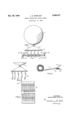
- Figure 1 is a view in elevation of a balloon ready for launching showing the rolls of streamers suspended below the balloon;
- Figure 2 is a view in elevation of a balloon in flight carrying unfurled streamers
- FIG. 3 illustrates the details of the streamer construction
- Figure 4 is a detail of a modified form of streamer construction.
- supporting bar 5 is shown attached by means of cords 6 to a balloon I, which may be inflated with hydrogen or other gas lighter-than-air.
- Aflixed to supporting bar 5 and spaced therealong are the ends of paper streamers which are arranged in rolls 8 placed upon a shaft 9.
- Vanes l0 comprise fins of cardboard or other suitable material fitted into slots at the ends of shaft 9.
- the vanes [0 present a large surface to the air thus retarding the unrolling due to gravity of the streamers wound in rolls 8 until the assembly has gained an appreciable altitude.
- the shaft 9 with its vanes l0 will be released and will drop to the ground.
- the ascending signal target then appears as in Figure 2 with the streamers presenting an array of resonant refleeting members l2 suspended below the balloon 1.
- This array reflects an appreciable portion of the radio frequency energy impinging thereon, and the echoes returned to the tracking means 3 provide signals whereby the course of the balloon may be followed.
- Strips of conducting material preferably metal foil, are glued or otherwise fastened length, one-fourth of an inch in width and were spaced approximately three. inches apart along the streamer. Under actual tests a plurality of streamers fifty to one hundred feet long have been satisfactorily employed.
- a curtain. i5- comprises two layers of paper ,or other dielectric material having resonant foil members glued or otherwise fastened therebe, tween.
- the curtain I5 is ribboned along. its length, thus forming a narrow paper streamer along which the resonant foil. members are uni..- iormly spaced.
- the ribboned portion terminates before each end of the curtainsuch that the streamers are kept suspended in an orderly fashion below the balloon when in flight and a mosaic of resonant reflecting members is thereby exposed to the tracking radio waves.
- the curtain l5 may be rolled up and attached to the balloon in a manner similar to thatdescribed in connection Withthe rolled paper steamers.
- rolled curtain may be slipped over shaft 9- in place of the rolls B'in Figure Land-the free end of thecurtain may be aflixed to supporting ⁇ par 5.
- the curtain Upon ascent of the assembly the curtain will ,unfurl and shaft 9 withits vanes 10 willbereleased.
- the resonant. foil members spaced on the curtain will then providean effectiue signal target.
- curtains from ten to twenty feet in length were employed satistac torily.
- both the individual-streamers and the curtain have beendescribed as having two layers of dielectric material
- the resonant foil members may; beidirectly aflixed: to a single layer of dielectric baqkingt Thou g ,:the resonant foil members have ,beendscribed as being carriedaloft by balloons
- the-streamers may be broadcast directly to the atmosphere from airplanes, or may be suspended below parachutes to provide aerial signal reflecting targets.
- a reflecting signal target comprising, aerial supporting means, a streamer of dielectric mater ial suspended from said supporting means, and
- An aerial target for reflecting radio waves comprising, an aerial vehicle, streamers of dielectrio material having aifixed thereto a plurality of resonant metal foil strips said streamers being rolled and fastened at their free ends to said vehicle, and automatic means whereby said streamers may be unrolled upon ascent of said yehicle.
- a reflecting radio signal target comprising, an aerial vehicle, streamers of dielectric material rolled and attached at one end to said vehicle, a plurality of foil strips of predetermined dimensions afiixed to andspaced along said streamers, and automatic means for permitting the gradual ,unrolling of said streamers upon ascent of said vehicle.
Landscapes
- Engineering & Computer Science (AREA)
- Radar, Positioning & Navigation (AREA)
- Remote Sensing (AREA)
- Physics & Mathematics (AREA)
- Electromagnetism (AREA)
- Aerials With Secondary Devices (AREA)
Description
NOV. 29, 1949 J, s N 2,489,337
AERIAL REFLECTING SIGNAL TARGET Filed Aug. 10, 1945 INVENTOR. JACOB GEORGE SPERLING iff rn y Patented Nov. 29, 1949 AERIAL REFLECTING SIGNAL TARGET Jacob George Sperling, Asbury Park, N. J., assignor to the United States of America as represented by the Secretary of War Application August 10, 1945, Serial No. 610,166
(Granted under the act of March 3, 1883, as amended April 30, 1928; 370 O. G. 757) 3 Claims.
The invention described herein may be manufactured and used by or for the Government for governmental purposes, without the payment to me of any royalty thereon.
This invention relates to meteorological instruments, and more particularly to reflecting signal targets.
In recent years it has become the practice to obtain meteorological information pertaining to the atmosphere at high altitudes through the use of balloons, by means of which meteorological instruments are carried aloft to record temperature, pressure and humidity. In employing this technique it is also desirable to track the course of balloons in flight in order to obtain data on the velocity and direction of winds at various altitudes. To make such determinations of practical value it is necessary to follow the course of balloons to high altitudes and over appreciable distances.
Although balloons have been tracked in the past by optical means, with the development of radar systems it has become feasible to track balloons by the use of radio waves. Transmitted pulses of high frequency radio energy are directed at the balloon, and the returned echo signals reflected therefrom provide continuous information as to the course of the balloon through the atmosphere. This method makes it possible to track the balloon over great distances and under varying conditions of weather and visibility.
In order to enhance the intensity of the echo signals, resonant targets may be suspended from the balloon to effectively reflect radio signals from a distant transmitter to its associated receiver. In this connection many types of resonant targets have been proposed. Reflecting foil members may be distributed at random within the balloon structure and caused to adhere to the surface thereof. These windows or chaff provide a fairly efiective reflecting surface. Other targets may consist of flat planes covered with sheets of foil, wire mesh, or other conducting material. This assembly may be suspended below the balloon by a cable or cord. While these corner reflectors provide excellent reflecting targets, their weight presents a disadvantage in using them with balloons Where a high rate of ascent is desirable.
According to the present invention, conducting means of a foil-strip nature having such dimensions as to be resonant at a predetermined frequency are mounted in end-to-end fashion on elongated paper strips or streamers. The resonant foil strips are spaced along the paper streamers at definite, predetermined intervals, each foil strip forming a resonant metallic member at the radio frequency being radiated by the tracking means. By employing a plurality of these paper streamers which are readily borne aloft by suitable means, a high average echo response to transmitted pulses is obtained, whereby the course of the target may be followed accurately over great distances.
It is, therefore, an object of the present invention to provide an effective light weight signal target.
A further object of the present invention is to provide a new and improved signal target having a yielding and practically unbreakable structure.
A still further object of the present invention is to provide a new and improved signal target which may be easily fabricated from a limited number of inexpensive components.
These and other objects and advantages of the present invention will become apparent from a perusal of the following detailed description, taken in connection with the accompanying drawings in which Figure 1 is a view in elevation of a balloon ready for launching showing the rolls of streamers suspended below the balloon;
Figure 2 is a view in elevation of a balloon in flight carrying unfurled streamers;
Figure 3 illustrates the details of the streamer construction; and
Figure 4 is a detail of a modified form of streamer construction.
Referring now to Figure 1, supporting bar 5 is shown attached by means of cords 6 to a balloon I, which may be inflated with hydrogen or other gas lighter-than-air. Aflixed to supporting bar 5 and spaced therealong are the ends of paper streamers which are arranged in rolls 8 placed upon a shaft 9. Vanes l0 comprise fins of cardboard or other suitable material fitted into slots at the ends of shaft 9. Upon releasing the assembly it will ascend rapidly. The vanes [0 present a large surface to the air thus retarding the unrolling due to gravity of the streamers wound in rolls 8 until the assembly has gained an appreciable altitude. When rolls 8 are completely unrolled, the shaft 9 with its vanes l0 will be released and will drop to the ground. The ascending signal target then appears as in Figure 2 with the streamers presenting an array of resonant refleeting members l2 suspended below the balloon 1. This array reflects an appreciable portion of the radio frequency energy impinging thereon, and the echoes returned to the tracking means 3 provide signals whereby the course of the balloon may be followed.
The streamer construction is shown in detail in Figure 3. Strips of conducting material, preferably metal foil, are glued or otherwise fastened length, one-fourth of an inch in width and were spaced approximately three. inches apart along the streamer. Under actual tests a plurality of streamers fifty to one hundred feet long have been satisfactorily employed.
In some applications it may be desirable to construct the streamers as shown in Figure 4. A curtain. i5- comprises two layers of paper ,or other dielectric material having resonant foil members glued or otherwise fastened therebe, tween. The curtain I5 is ribboned along. its length, thus forming a narrow paper streamer along which the resonant foil. members are uni..- iormly spaced. The ribboned portion terminates before each end of the curtainsuch that the streamers are kept suspended in an orderly fashion below the balloon when in flight and a mosaic of resonant reflecting members is thereby exposed to the tracking radio waves. The curtain l5 may be rolled up and attached to the balloon in a manner similar to thatdescribed in connection Withthe rolled paper steamers. The
rolled curtain may be slipped over shaft 9- in place of the rolls B'inFigure Land-the free end of thecurtain may be aflixed to supporting {par 5. Upon ascent of the assembly the curtain will ,unfurl and shaft 9 withits vanes 10 willbereleased. The resonant. foil members spaced on the curtain will then providean effectiue signal target. In. one embodiment curtains from ten to twenty feet in length were employed satistac torily.
Having. described the present invention it is understood that the specific examples are .citedby way of illustration-rather than by way-o, mitation. For example, both the individual-streamers and the curtain have beendescribed as having two layers of dielectric material If desired, the resonant foil members may; beidirectly aflixed: to a single layer of dielectric baqkingt Thou g ,:the resonant foil members have ,beendscribed as being carriedaloft by balloons, the-streamers may be broadcast directly to the atmosphere from airplanes, or may be suspended below parachutes to provide aerial signal reflecting targets. Many other modifications within the scope of the invention as set forth in the appended claims may ocour to persons skilled in the art.
What is claimed is:
l. A reflecting signal target comprising, aerial supporting means, a streamer of dielectric mater ial suspended from said supporting means, and
metal foil strips of predetermined dimensions attached longitudinally to said streamer and unip o spa ed t e e 2. An aerial target for reflecting radio waves comprising, an aerial vehicle, streamers of dielectrio material having aifixed thereto a plurality of resonant metal foil strips said streamers being rolled and fastened at their free ends to said vehicle, and automatic means whereby said streamers may be unrolled upon ascent of said yehicle.
'3; A reflecting radio signal target comprising, an aerial vehicle, streamers of dielectric material rolled and attached at one end to said vehicle, a plurality of foil strips of predetermined dimensions afiixed to andspaced along said streamers, and automatic means for permitting the gradual ,unrolling of said streamers upon ascent of said vehicle. H V H M JACOB GEORGEv SPERLING.
REFERENCES CITED The following references are of record in the file of this patent:
UNITED STATES PATENTS Number Name Date 1"-,096;82'2 Brandt May 19, 1914 1 ,320,980 Bowman Nov. 4, 19-19 1,334,947 Davis Mar. 30,1920 1,794,828 Bleriot Mar. 3, :1931 1,892,755 Scheppmann Jan. 3", 1933 2,151,336 Scharlau Mar. 21,1939 2,366,423 Pear, Jr. Jan. 2, 1945 2,382,065 Kappeler Aug. 14';- 1945 OREIGN PATENTS Number Country Date 295,613- aGreat Britain' Aug. 14, 1923 I 541,611 Germany June18, 1927 759,788 France Feb. 9, 193.4-
OTHER REFERENCES d n Daily Ex r Thursd Fe 24 1 4;
' page l, column l.-3{l 3-18;
Priority Applications (1)
| Application Number | Priority Date | Filing Date | Title |
|---|---|---|---|
| US610166A US2489337A (en) | 1945-08-10 | 1945-08-10 | Aerial reflecting signal target |
Applications Claiming Priority (1)
| Application Number | Priority Date | Filing Date | Title |
|---|---|---|---|
| US610166A US2489337A (en) | 1945-08-10 | 1945-08-10 | Aerial reflecting signal target |
Publications (1)
| Publication Number | Publication Date |
|---|---|
| US2489337A true US2489337A (en) | 1949-11-29 |
Family
ID=24443952
Family Applications (1)
| Application Number | Title | Priority Date | Filing Date |
|---|---|---|---|
| US610166A Expired - Lifetime US2489337A (en) | 1945-08-10 | 1945-08-10 | Aerial reflecting signal target |
Country Status (1)
| Country | Link |
|---|---|
| US (1) | US2489337A (en) |
Cited By (22)
| Publication number | Priority date | Publication date | Assignee | Title |
|---|---|---|---|---|
| US2756948A (en) * | 1952-12-05 | 1956-07-31 | Winzen Res Inc | Skin stressed balloon |
| US2881425A (en) * | 1954-03-19 | 1959-04-07 | Charles A Gregory | Method of producing radio wave reflector cords of varied length |
| US3122743A (en) * | 1956-04-20 | 1964-02-25 | Frank R Vlasic | Collapsible radar reflective device |
| US3229290A (en) * | 1953-03-06 | 1966-01-11 | Evan D Fisher | Releasable balloon decoys |
| US3228633A (en) * | 1953-03-05 | 1966-01-11 | Evan D Fisher | Balloon launching device |
| US3273062A (en) * | 1963-08-30 | 1966-09-13 | Litton Systems Inc | System of propagating radio energy by means of artificial scatterers |
| US4145111A (en) * | 1976-10-04 | 1979-03-20 | Saab-Scania Aktiebolag | Laser beam reflector assembly adapted for external attachment to target aircraft |
| US4688040A (en) * | 1984-11-28 | 1987-08-18 | General Dynamics, Pomona Division | Radar return suppressor |
| US4763127A (en) * | 1986-01-24 | 1988-08-09 | Tracor Aerospace Austin, Inc. | Fiber under foil chaff coil |
| US5410918A (en) * | 1992-08-13 | 1995-05-02 | University Corporation For Atmospheric Research | Ambient air sampler |
| US7363861B2 (en) | 2004-08-13 | 2008-04-29 | Armtec Defense Products Co. | Pyrotechnic systems and associated methods |
| US20080290087A1 (en) * | 2007-05-21 | 2008-11-27 | Rf Dynamics Ltd. | Electromagnetic heating |
| US7913625B2 (en) | 2006-04-07 | 2011-03-29 | Armtec Defense Products Co. | Ammunition assembly with alternate load path |
| US7994962B1 (en) * | 2007-07-17 | 2011-08-09 | Drosera Ltd. | Apparatus and method for concentrating electromagnetic energy on a remotely-located object |
| US8146502B2 (en) | 2006-01-06 | 2012-04-03 | Armtec Defense Products Co. | Combustible cartridge cased ammunition assembly |
| US8207479B2 (en) | 2006-02-21 | 2012-06-26 | Goji Limited | Electromagnetic heating according to an efficiency of energy transfer |
| US8492686B2 (en) | 2008-11-10 | 2013-07-23 | Goji, Ltd. | Device and method for heating using RF energy |
| US8653482B2 (en) | 2006-02-21 | 2014-02-18 | Goji Limited | RF controlled freezing |
| US8839527B2 (en) | 2006-02-21 | 2014-09-23 | Goji Limited | Drying apparatus and methods and accessories for use therewith |
| US9131543B2 (en) | 2007-08-30 | 2015-09-08 | Goji Limited | Dynamic impedance matching in RF resonator cavity |
| US9215756B2 (en) | 2009-11-10 | 2015-12-15 | Goji Limited | Device and method for controlling energy |
| US10674570B2 (en) | 2006-02-21 | 2020-06-02 | Goji Limited | System and method for applying electromagnetic energy |
Citations (11)
| Publication number | Priority date | Publication date | Assignee | Title |
|---|---|---|---|---|
| US1096822A (en) * | 1913-07-15 | 1914-05-19 | Emil Brandt | Process of coating webs of paper with leaf metal. |
| US1320980A (en) * | 1918-09-21 | 1919-11-04 | Western Electric Co | Transformer. |
| US1334947A (en) * | 1919-02-04 | 1920-03-30 | Francis R Coughlin | Apparatus for and method of manufacturing mounted gold-leaf |
| GB295613A (en) * | 1927-05-14 | 1928-08-14 | William Dunbar | A new or improved composition of matter for magnetic screening and other purposes |
| US1794828A (en) * | 1928-10-10 | 1931-03-03 | Bleriot Louis | Aerial advertising and signaling |
| DE541611C (en) * | 1932-01-14 | Hein | Support masts for directional antennas | |
| US1892755A (en) * | 1929-05-25 | 1933-01-03 | Lorenz C Ag | Method of making electrical condensers |
| FR759788A (en) * | 1933-08-18 | 1934-02-09 | New antenna of t. s. f. insulated for outdoor installations, on vehicles or ships | |
| US2151336A (en) * | 1934-07-05 | 1939-03-21 | Telefunken Gmbh | Radio signaling apparatus |
| US2366423A (en) * | 1942-08-17 | 1945-01-02 | Washington Inst Of Technology | Radiosonde antenna system |
| US2382065A (en) * | 1940-05-15 | 1945-08-14 | Micafil Ltd Works For Electric | Apparatus for producing wound condensers |
-
1945
- 1945-08-10 US US610166A patent/US2489337A/en not_active Expired - Lifetime
Patent Citations (11)
| Publication number | Priority date | Publication date | Assignee | Title |
|---|---|---|---|---|
| DE541611C (en) * | 1932-01-14 | Hein | Support masts for directional antennas | |
| US1096822A (en) * | 1913-07-15 | 1914-05-19 | Emil Brandt | Process of coating webs of paper with leaf metal. |
| US1320980A (en) * | 1918-09-21 | 1919-11-04 | Western Electric Co | Transformer. |
| US1334947A (en) * | 1919-02-04 | 1920-03-30 | Francis R Coughlin | Apparatus for and method of manufacturing mounted gold-leaf |
| GB295613A (en) * | 1927-05-14 | 1928-08-14 | William Dunbar | A new or improved composition of matter for magnetic screening and other purposes |
| US1794828A (en) * | 1928-10-10 | 1931-03-03 | Bleriot Louis | Aerial advertising and signaling |
| US1892755A (en) * | 1929-05-25 | 1933-01-03 | Lorenz C Ag | Method of making electrical condensers |
| FR759788A (en) * | 1933-08-18 | 1934-02-09 | New antenna of t. s. f. insulated for outdoor installations, on vehicles or ships | |
| US2151336A (en) * | 1934-07-05 | 1939-03-21 | Telefunken Gmbh | Radio signaling apparatus |
| US2382065A (en) * | 1940-05-15 | 1945-08-14 | Micafil Ltd Works For Electric | Apparatus for producing wound condensers |
| US2366423A (en) * | 1942-08-17 | 1945-01-02 | Washington Inst Of Technology | Radiosonde antenna system |
Cited By (45)
| Publication number | Priority date | Publication date | Assignee | Title |
|---|---|---|---|---|
| US2756948A (en) * | 1952-12-05 | 1956-07-31 | Winzen Res Inc | Skin stressed balloon |
| US3228633A (en) * | 1953-03-05 | 1966-01-11 | Evan D Fisher | Balloon launching device |
| US3229290A (en) * | 1953-03-06 | 1966-01-11 | Evan D Fisher | Releasable balloon decoys |
| US2881425A (en) * | 1954-03-19 | 1959-04-07 | Charles A Gregory | Method of producing radio wave reflector cords of varied length |
| US3122743A (en) * | 1956-04-20 | 1964-02-25 | Frank R Vlasic | Collapsible radar reflective device |
| US3273062A (en) * | 1963-08-30 | 1966-09-13 | Litton Systems Inc | System of propagating radio energy by means of artificial scatterers |
| US4145111A (en) * | 1976-10-04 | 1979-03-20 | Saab-Scania Aktiebolag | Laser beam reflector assembly adapted for external attachment to target aircraft |
| US4688040A (en) * | 1984-11-28 | 1987-08-18 | General Dynamics, Pomona Division | Radar return suppressor |
| US4763127A (en) * | 1986-01-24 | 1988-08-09 | Tracor Aerospace Austin, Inc. | Fiber under foil chaff coil |
| US5410918A (en) * | 1992-08-13 | 1995-05-02 | University Corporation For Atmospheric Research | Ambient air sampler |
| US7363861B2 (en) | 2004-08-13 | 2008-04-29 | Armtec Defense Products Co. | Pyrotechnic systems and associated methods |
| US8146502B2 (en) | 2006-01-06 | 2012-04-03 | Armtec Defense Products Co. | Combustible cartridge cased ammunition assembly |
| US8807038B1 (en) | 2006-01-06 | 2014-08-19 | Armtec Defense Products Co. | Combustible cartridge cased ammunition assembly |
| US9872345B2 (en) | 2006-02-21 | 2018-01-16 | Goji Limited | Food preparation |
| US9167633B2 (en) | 2006-02-21 | 2015-10-20 | Goji Limited | Food preparation |
| US10080264B2 (en) | 2006-02-21 | 2018-09-18 | Goji Limited | Food preparation |
| US8207479B2 (en) | 2006-02-21 | 2012-06-26 | Goji Limited | Electromagnetic heating according to an efficiency of energy transfer |
| US10674570B2 (en) | 2006-02-21 | 2020-06-02 | Goji Limited | System and method for applying electromagnetic energy |
| US11057968B2 (en) | 2006-02-21 | 2021-07-06 | Goji Limited | Food preparation |
| US11523474B2 (en) | 2006-02-21 | 2022-12-06 | Goji Limited | Electromagnetic heating |
| US11729871B2 (en) | 2006-02-21 | 2023-08-15 | Joliet 2010 Limited | System and method for applying electromagnetic energy |
| US8653482B2 (en) | 2006-02-21 | 2014-02-18 | Goji Limited | RF controlled freezing |
| US8759729B2 (en) | 2006-02-21 | 2014-06-24 | Goji Limited | Electromagnetic heating according to an efficiency of energy transfer |
| US10492247B2 (en) | 2006-02-21 | 2019-11-26 | Goji Limited | Food preparation |
| US8839527B2 (en) | 2006-02-21 | 2014-09-23 | Goji Limited | Drying apparatus and methods and accessories for use therewith |
| US8941040B2 (en) | 2006-02-21 | 2015-01-27 | Goji Limited | Electromagnetic heating |
| US9040883B2 (en) | 2006-02-21 | 2015-05-26 | Goji Limited | Electromagnetic heating |
| US9078298B2 (en) | 2006-02-21 | 2015-07-07 | Goji Limited | Electromagnetic heating |
| US8136451B2 (en) | 2006-04-07 | 2012-03-20 | Armtec Defense Products Co. | Ammunition assembly with alternate load path |
| US7913625B2 (en) | 2006-04-07 | 2011-03-29 | Armtec Defense Products Co. | Ammunition assembly with alternate load path |
| US8430033B2 (en) * | 2006-04-07 | 2013-04-30 | Armtec Defense Products Co. | Ammunition assembly with alternate load path |
| US20120291652A1 (en) * | 2006-04-07 | 2012-11-22 | Armtec Defense Products Co. | Ammunition assembly with alternate load path |
| US8389916B2 (en) | 2007-05-21 | 2013-03-05 | Goji Limited | Electromagnetic heating |
| US20080290087A1 (en) * | 2007-05-21 | 2008-11-27 | Rf Dynamics Ltd. | Electromagnetic heating |
| US7994962B1 (en) * | 2007-07-17 | 2011-08-09 | Drosera Ltd. | Apparatus and method for concentrating electromagnetic energy on a remotely-located object |
| US9131543B2 (en) | 2007-08-30 | 2015-09-08 | Goji Limited | Dynamic impedance matching in RF resonator cavity |
| US11129245B2 (en) | 2007-08-30 | 2021-09-21 | Goji Limited | Dynamic impedance matching in RF resonator cavity |
| US10687395B2 (en) | 2008-11-10 | 2020-06-16 | Goji Limited | Device for controlling energy |
| US9374852B2 (en) | 2008-11-10 | 2016-06-21 | Goji Limited | Device and method for heating using RF energy |
| US11653425B2 (en) | 2008-11-10 | 2023-05-16 | Joliet 2010 Limited | Device and method for controlling energy |
| US8492686B2 (en) | 2008-11-10 | 2013-07-23 | Goji, Ltd. | Device and method for heating using RF energy |
| US10405380B2 (en) | 2009-11-10 | 2019-09-03 | Goji Limited | Device and method for heating using RF energy |
| US9609692B2 (en) | 2009-11-10 | 2017-03-28 | Goji Limited | Device and method for controlling energy |
| US10999901B2 (en) | 2009-11-10 | 2021-05-04 | Goji Limited | Device and method for controlling energy |
| US9215756B2 (en) | 2009-11-10 | 2015-12-15 | Goji Limited | Device and method for controlling energy |
Similar Documents
| Publication | Publication Date | Title |
|---|---|---|
| US2489337A (en) | Aerial reflecting signal target | |
| US4023408A (en) | Stormscope | |
| Stroud et al. | Rocket‐grenade measurements of temperatures and winds in the mesosphere over Churchill, Canada | |
| US4471358A (en) | Re-entry chaff dart | |
| Bowman et al. | Multihour stratospheric flights with the heliotrope solar hot-air balloon | |
| US5940023A (en) | Parachute apparatus having enhanced radar reflective characteristics | |
| Willis | Radar observations of ice spheres in free fall | |
| US3381293A (en) | Radar markers | |
| Swaim et al. | Performance characterization of heliotrope solar hot-air balloons during multihour stratospheric flights | |
| Lhermitte | Note on the observation of small-scale atmospheric turbulence by Doppler radar techniques | |
| US3529794A (en) | Radar responsive parachute | |
| Ksanfomaliti et al. | Acoustic measurements of the wind velocity at the Venera-13 and Venera-14 landing sites | |
| Lamberth et al. | mountain lee waves at White Sands Missile Range | |
| Miś et al. | Stratospheric VLF vertical electric mono-and dipole antenna tests in 2014–2015 | |
| Black et al. | Appearance of the sea surface in tropical cyclones | |
| US3005605A (en) | Automatic homing aircraft | |
| Murphy et al. | Gun-launched probes over Barbados | |
| Maglieri et al. | Sonic-boom measurements for SR-71 aircraft operating at Mach numbers to 3.0 and altitudes to 24384 meters | |
| Fletcher | Early developments of weather radar during World War II | |
| Smith | Monthly wind measurements in the mesodecline over a one‐year period | |
| Jenkins et al. | Rocket sounding of high atmosphere meteorological parameters | |
| Webb et al. | Meteorological Rocket Network probing of the stratosphere and lower mesosphere | |
| Lewis et al. | Flight Measurements of Boundary-layer Noise on the X-15 | |
| Maglieri et al. | Ground Measurements of the Shock-Wave Noise From Supersonic Bomber Airplanes in the Altitude Range From 30,000 to 50,000 Feet | |
| US3058346A (en) | System for measurement of air temperature at ground level |