JP5639617B2 - Sticking device and sticking method - Google Patents
Sticking device and sticking method Download PDFInfo
- Publication number
- JP5639617B2 JP5639617B2 JP2012110098A JP2012110098A JP5639617B2 JP 5639617 B2 JP5639617 B2 JP 5639617B2 JP 2012110098 A JP2012110098 A JP 2012110098A JP 2012110098 A JP2012110098 A JP 2012110098A JP 5639617 B2 JP5639617 B2 JP 5639617B2
- Authority
- JP
- Japan
- Prior art keywords
- support
- laminate
- plate member
- substrate
- plate
- Prior art date
- Legal status (The legal status is an assumption and is not a legal conclusion. Google has not performed a legal analysis and makes no representation as to the accuracy of the status listed.)
- Active
Links
Images

Classifications
-
- H—ELECTRICITY
- H01—ELECTRIC ELEMENTS
- H01L—SEMICONDUCTOR DEVICES NOT COVERED BY CLASS H10
- H01L21/00—Processes or apparatus adapted for the manufacture or treatment of semiconductor or solid state devices or of parts thereof
- H01L21/67—Apparatus specially adapted for handling semiconductor or electric solid state devices during manufacture or treatment thereof; Apparatus specially adapted for handling wafers during manufacture or treatment of semiconductor or electric solid state devices or components ; Apparatus not specifically provided for elsewhere
- H01L21/67005—Apparatus not specifically provided for elsewhere
- H01L21/67011—Apparatus for manufacture or treatment
- H01L21/67092—Apparatus for mechanical treatment
-
- B—PERFORMING OPERATIONS; TRANSPORTING
- B30—PRESSES
- B30B—PRESSES IN GENERAL
- B30B15/00—Details of, or accessories for, presses; Auxiliary measures in connection with pressing
- B30B15/06—Platens or press rams
-
- B—PERFORMING OPERATIONS; TRANSPORTING
- B30—PRESSES
- B30B—PRESSES IN GENERAL
- B30B15/00—Details of, or accessories for, presses; Auxiliary measures in connection with pressing
- B30B15/32—Discharging presses
-
- B—PERFORMING OPERATIONS; TRANSPORTING
- B32—LAYERED PRODUCTS
- B32B—LAYERED PRODUCTS, i.e. PRODUCTS BUILT-UP OF STRATA OF FLAT OR NON-FLAT, e.g. CELLULAR OR HONEYCOMB, FORM
- B32B37/00—Methods or apparatus for laminating, e.g. by curing or by ultrasonic bonding
- B32B37/10—Methods or apparatus for laminating, e.g. by curing or by ultrasonic bonding characterised by the pressing technique, e.g. using action of vacuum or fluid pressure
-
- B—PERFORMING OPERATIONS; TRANSPORTING
- B29—WORKING OF PLASTICS; WORKING OF SUBSTANCES IN A PLASTIC STATE IN GENERAL
- B29C—SHAPING OR JOINING OF PLASTICS; SHAPING OF MATERIAL IN A PLASTIC STATE, NOT OTHERWISE PROVIDED FOR; AFTER-TREATMENT OF THE SHAPED PRODUCTS, e.g. REPAIRING
- B29C43/00—Compression moulding, i.e. applying external pressure to flow the moulding material; Apparatus therefor
- B29C43/32—Component parts, details or accessories; Auxiliary operations
- B29C43/56—Compression moulding under special conditions, e.g. vacuum
- B29C2043/561—Compression moulding under special conditions, e.g. vacuum under vacuum conditions
-
- B—PERFORMING OPERATIONS; TRANSPORTING
- B29—WORKING OF PLASTICS; WORKING OF SUBSTANCES IN A PLASTIC STATE IN GENERAL
- B29C—SHAPING OR JOINING OF PLASTICS; SHAPING OF MATERIAL IN A PLASTIC STATE, NOT OTHERWISE PROVIDED FOR; AFTER-TREATMENT OF THE SHAPED PRODUCTS, e.g. REPAIRING
- B29C43/00—Compression moulding, i.e. applying external pressure to flow the moulding material; Apparatus therefor
- B29C43/02—Compression moulding, i.e. applying external pressure to flow the moulding material; Apparatus therefor of articles of definite length, i.e. discrete articles
- B29C43/20—Making multilayered or multicoloured articles
- B29C43/203—Making multilayered articles
-
- B—PERFORMING OPERATIONS; TRANSPORTING
- B32—LAYERED PRODUCTS
- B32B—LAYERED PRODUCTS, i.e. PRODUCTS BUILT-UP OF STRATA OF FLAT OR NON-FLAT, e.g. CELLULAR OR HONEYCOMB, FORM
- B32B2309/00—Parameters for the laminating or treatment process; Apparatus details
- B32B2309/02—Temperature
-
- B—PERFORMING OPERATIONS; TRANSPORTING
- B32—LAYERED PRODUCTS
- B32B—LAYERED PRODUCTS, i.e. PRODUCTS BUILT-UP OF STRATA OF FLAT OR NON-FLAT, e.g. CELLULAR OR HONEYCOMB, FORM
- B32B2309/00—Parameters for the laminating or treatment process; Apparatus details
- B32B2309/04—Time
-
- B—PERFORMING OPERATIONS; TRANSPORTING
- B32—LAYERED PRODUCTS
- B32B—LAYERED PRODUCTS, i.e. PRODUCTS BUILT-UP OF STRATA OF FLAT OR NON-FLAT, e.g. CELLULAR OR HONEYCOMB, FORM
- B32B2309/00—Parameters for the laminating or treatment process; Apparatus details
- B32B2309/08—Dimensions, e.g. volume
- B32B2309/10—Dimensions, e.g. volume linear, e.g. length, distance, width
-
- B—PERFORMING OPERATIONS; TRANSPORTING
- B32—LAYERED PRODUCTS
- B32B—LAYERED PRODUCTS, i.e. PRODUCTS BUILT-UP OF STRATA OF FLAT OR NON-FLAT, e.g. CELLULAR OR HONEYCOMB, FORM
- B32B2309/00—Parameters for the laminating or treatment process; Apparatus details
- B32B2309/12—Pressure
-
- B—PERFORMING OPERATIONS; TRANSPORTING
- B32—LAYERED PRODUCTS
- B32B—LAYERED PRODUCTS, i.e. PRODUCTS BUILT-UP OF STRATA OF FLAT OR NON-FLAT, e.g. CELLULAR OR HONEYCOMB, FORM
- B32B41/00—Arrangements for controlling or monitoring lamination processes; Safety arrangements
Description
本発明は、押圧力を加えることにより、基板と支持体とを接着層を介して貼り付ける貼付装置および貼付方法に関する。 The present invention relates to a pasting apparatus and a pasting method for pasting a substrate and a support through an adhesive layer by applying a pressing force.
接着層を介して基板と支持体とを貼り付ける貼付技術として、例えば、特許文献1には、減圧プレス機における所定温度に加熱した上下一対の熱盤間に、半導体或いはセラミックスからなる無機基板を含む積層材と積層加工用の補助材料との組み合わせセットを設置して、上記組み合わせセットに上記一対の熱盤を接触させた後、少なくとも加圧開始から0.05MPaまでの低圧負荷を10秒間以上かけて行う無機基板のプレス加工法が記載されている。 As an application technique for attaching a substrate and a support through an adhesive layer, for example, Patent Document 1 discloses an inorganic substrate made of a semiconductor or ceramics between a pair of upper and lower heating plates heated to a predetermined temperature in a vacuum press. After installing the combination set of the laminated material and the auxiliary material for lamination processing and bringing the pair of hot plates into contact with the combination set, a low pressure load of at least 0.05 MPa from the start of pressurization is 10 seconds or more. The method of pressing an inorganic substrate is described.
しかしながら、本発明者等が検討したところ、例えばウエハ基板等の基板と当該基板を支持する支持体とを接着層を介して貼り付けるために、特許文献1に記載されているような従来のプレス加工法を用いた場合には、以下の問題点が生じることが分かった。即ち、上下一対のプレート部材を備えたプレス機を用い、プレート部材で基板及び支持体を挟み込んで押圧すると、プレート部材と支持体又は基板とが密着し、プレート部材および支持体の平面度が高い場合、基板及び支持体が、上側のプレート部材に貼り付いた状態となる場合がある。このような場合には、基板及び支持体をプレス機から搬出することが難しくなる。 However, when the present inventors examined, for example, in order to attach a substrate such as a wafer substrate and a support supporting the substrate via an adhesive layer, a conventional press as described in Patent Document 1 is used. It has been found that the following problems occur when the processing method is used. That is, when a press machine including a pair of upper and lower plate members is used and the substrate and the support are sandwiched and pressed by the plate members, the plate member and the support or the substrate are brought into close contact with each other, and the flatness of the plate member and the support is high. In some cases, the substrate and the support may be attached to the upper plate member. In such a case, it becomes difficult to carry out the substrate and the support from the press.
本発明は、上記課題に鑑みてなされたものであり、上下一対のプレート部材を備え、基板と支持体とを接着層を介して貼り付ける貼付装置において、接着層を介して貼り付けられた基板及び支持体が、上側のプレート部材に貼り付くことを防止するための技術を提供することを主たる目的とする。 The present invention has been made in view of the above problems, and includes a substrate pasted through an adhesive layer in a pasting apparatus that includes a pair of upper and lower plate members and pastes the substrate and the support through the adhesive layer. And it aims at providing the technique for preventing a support body sticking to an upper plate member.
上記の課題を解決するために、本発明に係る貼付装置は、基板と、接着層と、上記基板を支持する支持体とをこの順に積層してなる積層体に押圧力を加えることにより、上記基板と支持体とを接着層を介して貼り付ける貼付装置であって、積層体を挟み込む上下一対のプレート部材を備え、上側のプレート部材における積層体と接する部位に、当該プレート部材への積層体の貼り付きを防止する防止部が設けられていることを特徴としている。 In order to solve the above-described problem, the pasting device according to the present invention applies the pressing force to a laminate formed by laminating a substrate, an adhesive layer, and a support that supports the substrate in this order. A pasting device for pasting a substrate and a support through an adhesive layer, comprising a pair of upper and lower plate members sandwiching the laminate, and a laminate on the plate member at a portion in contact with the laminate in the upper plate member It is characterized in that a prevention part for preventing the sticking is provided.
また、本発明に係る貼付方法は、基板と、接着層と、上記基板を支持する支持体とをこの順に積層してなる積層体に押圧力を加えることにより、上記基板と支持体とを接着層を介して貼り付ける貼付方法であって、上下一対のプレート部材によって積層体を挟み込んで押圧する貼付工程と、貼付工程の後、一対のプレート部材を互いに離間させる離間工程とを包含しており、離間工程では、上側のプレート部材における積層体と接する部位に設けられた防止部が、上側のプレート部材へ積層体が貼り付くことを防止することを特徴としている。 Further, the sticking method according to the present invention bonds the substrate and the support by applying a pressing force to the laminate formed by laminating the substrate, the adhesive layer, and the support that supports the substrate in this order. A pasting method for pasting through a layer, which includes a pasting step of sandwiching and pressing the laminated body by a pair of upper and lower plate members, and a separating step of separating the pair of plate members from each other after the pasting step In the separation step, the prevention portion provided at a portion of the upper plate member that contacts the laminated body prevents the laminated body from sticking to the upper plate member.
本発明によれば、上側のプレート部材への積層体の貼り付きを防止することができる。 According to the present invention, it is possible to prevent the laminate from sticking to the upper plate member.
本発明に係る貼付装置は、基板と、接着層と、上記基板を支持する支持体とをこの順に積層してなる積層体に押圧力を加えることにより、上記基板と支持体とを接着層を介して貼り付ける貼付装置であって、積層体を挟み込む上下一対のプレート部材を備え、上側のプレート部材における積層体と接する部位に、当該プレート部材への積層体の貼り付きを防止する防止部が設けられている構成である。 The sticking device according to the present invention applies a pressing force to a laminate formed by laminating a substrate, an adhesive layer, and a support that supports the substrate in this order, thereby attaching the adhesive layer to the substrate and the support. And a pair of upper and lower plate members that sandwich the laminate, and a prevention unit that prevents the laminate from sticking to the plate member at a portion in contact with the laminate in the upper plate member. It is the structure provided.
〔積層体〕
貼付の対象となる積層体は、基板と、例えば熱可塑性樹脂を含む接着層と、上記基板を支持するサポートプレート(支持体)とがこの順に積層されて形成されている。即ち、積層体は、基板およびサポートプレートの何れか一方に接着剤が塗布されることによって、または、接着剤が塗布されてなる接着テープを貼着することによって接着層が形成された後、基板と、接着層と、サポートプレートとがこの順に積層されることによって形成されている。そして、積層体は、予め積層されて形成された後、例えば、ロボットアーム等の搬送装置によって、貼付装置の所定位置に載置(セット)される。上記積層体は、予め積層されて形成された状態で、基板とサポートプレートとの相対位置がずれないように、仮止めされていることがより好ましい。或いは、積層体は、例えば、ロボットアーム等の搬送装置によって、貼付装置のプレート部材上で基板およびサポートプレートが積層されて形成されることにより、貼付装置の所定位置に載置(セット)されてもよい。
[Laminate]
The laminate to be affixed is formed by laminating a substrate, an adhesive layer containing, for example, a thermoplastic resin, and a support plate (support) that supports the substrate in this order. That is, the laminated body is formed by applying an adhesive to one of the substrate and the support plate, or after adhering an adhesive tape to which the adhesive is applied to form an adhesive layer. And an adhesive layer and a support plate are laminated in this order. And after a laminated body is laminated | stacked beforehand and formed, it is mounted (set) in the predetermined position of a sticking apparatus by conveyance apparatuses, such as a robot arm, for example. It is more preferable that the laminate is temporarily fixed so that the relative position between the substrate and the support plate is not shifted in a state where the laminate is formed in advance. Alternatively, the laminated body is placed (set) on a predetermined position of the sticking device by, for example, forming a substrate and a support plate on the plate member of the sticking device by a transport device such as a robot arm. Also good.
尚、積層体を形成する形成方法および形成装置、つまり、接着層の形成方法や接着層形成装置、並びに、基板およびサポートプレートの重ね合わせ方法や重ね合わせ装置は、特に限定されるものではなく、種々の方法や装置を採用することができる。本発明においては、積層体は、貼付装置によって押圧力が加えられる時点で、基板と、接着層と、サポートプレートとがこの順に積層されて形成されていればよい。 In addition, the forming method and forming apparatus for forming the laminate, that is, the method for forming the adhesive layer and the adhesive layer forming apparatus, and the method for overlaying the substrate and the support plate and the overlay apparatus are not particularly limited, Various methods and apparatuses can be employed. In the present invention, the laminated body only needs to be formed by laminating the substrate, the adhesive layer, and the support plate in this order when the pressing force is applied by the sticking device.
上記基板は、サポートプレートに支持された(貼り付けられた)状態で、薄化、搬送、実装等のプロセスに供される。基板は、ウエハ基板に限定されず、例えば、サポートプレートによる支持が必要なセラミックス基板、薄いフィルム基板、フレキシブル基板等の任意の基板であってもよい。 The substrate is subjected to processes such as thinning, conveyance, and mounting while being supported (attached) to a support plate. The substrate is not limited to a wafer substrate, and may be any substrate such as a ceramic substrate, a thin film substrate, or a flexible substrate that needs to be supported by a support plate.
上記サポートプレートは、基板を支持する支持体であり、接着層を介して基板に貼り付けられる。そのため、サポートプレートは、基板の薄化、搬送、実装等のプロセス時に、基板の破損または変形を防ぐために必要な強度を有していればよく、より軽量であることが望ましい。以上の観点から、サポートプレートは、ガラス、シリコン、アクリル系樹脂、セラミック等で構成されていることがより好ましい。 The support plate is a support that supports the substrate, and is attached to the substrate via an adhesive layer. Therefore, the support plate only needs to have a strength necessary to prevent breakage or deformation of the substrate during a process such as thinning, transporting, and mounting of the substrate, and is desirably lighter. From the above viewpoint, the support plate is more preferably made of glass, silicon, acrylic resin, ceramic, or the like.
上記接着層を構成する接着剤は、例えば、加熱することによって熱流動性が向上する熱可塑性樹脂を接着材料として含んでいればよい。熱可塑性樹脂としては、例えば、アクリル系樹脂、スチレン系樹脂、マレイミド系樹脂、炭化水素系樹脂、エラストマー等が挙げられる。 The adhesive which comprises the said contact bonding layer should just contain the thermoplastic resin which heat fluidity improves by heating, for example as an adhesive material. Examples of the thermoplastic resin include acrylic resins, styrene resins, maleimide resins, hydrocarbon resins, and elastomers.
接着層の形成方法、即ち、基板またはサポートプレートに接着剤を塗布する塗布方法、或いは、基材に接着剤を塗布して接着テープを形成する形成方法は、特に限定されるものではないが、接着剤の塗布方法としては、例えば、スピンコート法、ディッピング法、ローラーブレード法、ドクターブレード法、スプレー法、スリットノズルによる塗布法等が挙げられる。 The method for forming the adhesive layer, that is, the method for applying the adhesive to the substrate or the support plate, or the method for forming the adhesive tape by applying the adhesive to the substrate is not particularly limited. Examples of the method for applying the adhesive include a spin coating method, a dipping method, a roller blade method, a doctor blade method, a spray method, and a coating method using a slit nozzle.
接着層の厚さは、貼り付けの対象となる基板およびサポートプレートの種類、貼り付け後の基板に施される処理等に応じて適宜設定すればよいが、10〜150μmの範囲内であることが好ましく、15〜100μmの範囲内であることがより好ましい。 The thickness of the adhesive layer may be set as appropriate according to the type of substrate to be pasted and the type of support plate, the treatment applied to the substrate after pasting, etc., but within the range of 10 to 150 μm. Is preferable, and it is more preferable that it exists in the range of 15-100 micrometers.
尚、基板からサポートプレートを剥離するときには、接着層に溶剤を供給して接着層を溶解すればよい。これにより、基板とサポートプレートとを分離することができる。このとき、サポートプレートに、その厚さ方向に貫通する貫通孔が形成されていれば、この貫通孔を介して接着層に溶剤を容易に供給することができるので、より好ましい。 When the support plate is peeled from the substrate, a solvent is supplied to the adhesive layer to dissolve the adhesive layer. Thereby, a board | substrate and a support plate can be isolate | separated. At this time, if the support plate has a through-hole penetrating in the thickness direction, it is more preferable because the solvent can be easily supplied to the adhesive layer through the through-hole.
また、基板とサポートプレートとの間には、貼り付けを妨げない限り、接着層以外の他の層がさらに形成されていてもよい。例えば、サポートプレートと接着層との間に、光を照射することによって変質する分離層が形成されていてもよい。分離層が形成されていることにより、基板の薄化、搬送、実装等のプロセス後に光を照射することで、基板とサポートプレートとを容易に分離することができる。 Further, a layer other than the adhesive layer may be further formed between the substrate and the support plate as long as the attachment is not hindered. For example, a separation layer that is altered by irradiation with light may be formed between the support plate and the adhesive layer. Since the separation layer is formed, the substrate and the support plate can be easily separated by irradiating light after processes such as thinning, transporting, and mounting of the substrate.
〔貼付装置〕
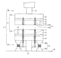
本実施形態に係る貼付装置について、図1を参照しながら以下に説明する。図1に示すように、本実施形態に係る貼付装置1は、積層体(図示しない)を挟み込む一対のプレート部材2と、プレート部材2を支持する支柱部材3とを備えている。貼付装置1は、貼付時に密閉することが可能で、吸引装置等を用いてその内部を減圧環境にすることができるチャンバー(図示しない)内に収容されている。
[Paste device]
The sticking apparatus according to the present embodiment will be described below with reference to FIG. As shown in FIG. 1, the sticking device 1 according to this embodiment includes a pair of
プレート部材2は、円盤状の外観を有し、上下方向に配設された下側プレート部材2aおよび上側プレート部材2bで構成されている。
The
下側プレート部材2aは、積層体と接する部位であって例えば基板側を下にして積層体が載置される載置プレート12と、支柱部材3の下側支持部材3aの中心支持部材31に固定される部位である支持プレート14と、載置プレート12および支持プレート14間に設けられた中間プレート13とで構成されている。上記載置プレート12および中間プレート13は、アルミナ等のセラミックスで形成されている。また、載置プレート12と中間プレート13との間には、下側プレート部材2aを加熱することによって押圧時に積層体を50〜300℃に加熱する、例えば面ヒータやリボンヒータ等の加熱装置(図示しない)が挟み込まれている。つまり、下側プレート部材2aは、加熱装置を内蔵している。上記支持プレート14は、ステンレス等の金属またはセラミックスや石等で形成されている。中間プレート13は、加熱装置と支持プレート14との短絡を防止する絶縁体としての機能を有している。また、支持プレート14が金属で形成されている場合は下側プレート部材2aの下側支持部材3aへの固定が容易となっている。尚、載置プレート12、中間プレート13および支持プレート14は、複数のボルトおよびナットで互いに固定されている。
The
載置プレート12は、非押圧時の平面度が1.0μm以下となるように、その表面が形成されている。ここで、上記平面度とは、平面に対する凹凸の度合いを示す数値であり、「平面度が1.0μm以下」とは、非押圧時の載置プレート12(および後述する押圧プレート22)表面の凹凸が±1.0μm以下であることを指す。また、載置プレート12は、押圧時の撓み量を低減することができるように、例えば35mm以上の厚さ(上下方向の厚さ)を有している。載置プレート12はセラミックスで形成されているので、その表面の平面度を1.0μm以下となるように容易に加工することができる。また、セラミックスは、金属と比較して、熱膨張率が小さいので加熱状態での押圧時の載置プレート12表面および押圧プレート22表面の湾曲やゆがみ等を小さくすること、つまり、湾曲やゆがみ等が生じ難いので上記各表面の平面性(水平性)を維持することができる。
The surface of the
下側プレート部材2aは、さらに、載置プレート12表面の温度を測定する例えば熱電対等からなる温度計16を備えると共に、載置プレート12における積層体と接する部位に、搬送装置による搬送動作を容易にするために、積層体の搬送時に当該積層体を持ち上げる複数の搬送用ピン17…を備えている。
The
上側プレート部材2bは、積層体と接する部位であって例えばサポートプレートを押圧する押圧プレート22と、支柱部材3の上側支持部材3bの中心支持部材41に固定される部位である支持プレート24と、押圧プレート22および支持プレート24間に設けられた中間プレート23とで構成されている。上記押圧プレート22および中間プレート23は、アルミナ等のセラミックスで形成されている。また、押圧プレート22と中間プレート23との間には、上側プレート部材2bを加熱することによって押圧時に積層体を50〜300℃に加熱する、例えば面ヒータやリボンヒータ等の加熱装置(図示しない)が挟み込まれている。つまり、上側プレート部材2bは、加熱装置を内蔵している。上記支持プレート24は、ステンレス等の金属またはセラミックスや石等で形成されている。中間プレート23は、加熱装置と支持プレート24との短絡を防止する絶縁体としての機能を有している。また、支持プレート24が金属で形成されている場合は上側プレート部材2bの上側支持部材3bへの固定が容易となっている。尚、押圧プレート22、中間プレート23および支持プレート24は、複数のボルトおよびナットで互いに固定されている。
The
押圧プレート22は、非押圧時の平面度が1.0μm以下となるように、その表面が形成されている。また、押圧プレート22は、押圧時の撓み量を低減することができるように、例えば35mm以上の厚さ(上下方向の厚さ)を有している。押圧プレート22はセラミックスで形成されているので、その表面の平面度を1.0μm以下となるように容易に加工することができる。
The surface of the
上側プレート部材2bは、さらに、押圧プレート22表面の温度を測定する例えば熱電対等からなる温度計16を備えると共に、押圧プレート22における積層体と接する部位に、上側プレート部材2bへの積層体の貼り付きを防止する複数の防止部材(防止部)27…を備えている。
The
上記防止部材27は、積層体を押圧した後、下側プレート部材2a及び上側プレート部材2bを離間させたときに、上側プレート部材2bへの積層体の貼り付きを防止する部材である。
The
ここで、防止部材27が無い場合、プレート部材2によって積層体を押圧したとき、上側プレート部材2bの押圧プレート22表面と積層体とは密着し、押圧プレート22表面および積層体の表面の平面度が高い場合、積層体が上側プレート部材2bに貼り付いてしまう場合がある。特に、押圧プレート22の非押圧時の平面度が1.0μm以下である場合、押圧プレート22表面に積層体が貼り付き易くなる。
Here, when there is no
これに対し、防止部材27は、積層体を上側プレート部材2bから離れる方向に押圧するようになっている。この押圧の力と積層体の自重とが合わさることによって、積層体が上側プレート部材2bに貼り付くことを首尾よく防止することができる。
On the other hand, the
即ち、一実施形態において、防止部材27は、ステンレス等の金属で形成されており、図2(a)及び(b)に示すように、ピン(押圧部材)27aと、このピン27aを押圧プレート22表面から突出するように弾性的に付勢するバネ27bとで構成されている。
That is, in one embodiment, the
バネ27bの付勢力は、図2(a)に示すように、積層体を押圧しているときにピン27aが押圧プレート22内部の凹部28に押し込まれ、図2(b)に示すように、積層体の押圧が解除されるとピン27aが押圧プレート22表面から突出するように調節されている。これにより、積層体を押圧した後、下側プレート部材2a及び上側プレート部材2bを離間させたときに、積層体に対し、上側プレート部材2bから離れる方向に力を加えることができる。この力と積層体の自重とが合わさることによって、上側プレート部材2bへの積層体の貼り付きを防止することができる。バネ27bの強さは、積層体のサイズや重さ等に応じて適宜設定すればよい。
As shown in FIG. 2A, the urging force of the
また、ピン27aの積層体と接触する側の先端Aは、積層体に疵を付けないように丸められていることがより好ましい。また、防止部材27…の配置数は特に限定されないが、積層体を安定して押圧し得る数が配置されていることが好ましく、一例において、押圧プレート22上に3箇所設けることができる。
Moreover, it is more preferable that the tip A of the
また、他の実施形態において、押圧プレート22には、防止部材27…に代えて又は加えて、押圧プレート22から積層体に向かって気体を送出する送出部(防止部)29が設けられていてもよい。
In another embodiment, the
送出部29が押圧プレート22から積層体に向かって気体を送出することにより、積層体を下方に押圧し、積層体が上側プレート部材2bに貼り付いてしまうことを首尾よく防止することができる。
By sending the gas from the
なお、送出部29が送出する気体は特に限定されず、例えば、窒素等のガスを用いることができる。また、送出部29は、積層体が押圧プレート22に貼り付かないように気体を送出すればよく、送出する気体の流量は特に限定されない。また、送出部29は、押圧プレート22に複数設けてもよい。
In addition, the gas which the sending
上記搬送用ピン17は、押圧動作の前後における搬送装置による搬送動作を容易にするために、積層体の搬送時に当該積層体を持ち上げる部材である。搬送用ピン17は、先端が丸く形成されたステンレス等の金属で構成されており、載置プレート12内部に移動可能に設置されている。そして、当該搬送用ピン17は、例えば上記制御部によって、積層体を押圧しているときに載置プレート12内部に収容され、積層体の押圧が解除されると載置プレート12表面から突出するように、その動作が制御されている。これにより、搬送用ピン17は、基板に疵を付けることなく、積層体の搬送時に当該積層体を載置プレート12表面から持ち上げて、搬送装置による搬送動作を容易にするようになっている。
The
支柱部材3は、上下方向に配設され、下側プレート部材2aを支持する下側支持部材3a、および、上側プレート部材2bを支持する上側支持部材3bで構成されている。これら下側支持部材3aおよび上側支持部材3bは、ステンレス等の金属またはセラミックスや石等で形成されている。
The
下側支持部材3aは、土台30に固定され、下側プレート部材2aの少なくとも中心部を支持する中心支持部材31と、土台30に固定され、下側プレート部材2aの中心部以外を支持する複数の周辺支持部材32…とで構成されている。そして、下側支持部材3aは、下側プレート部材2aを、載置プレート12の表面が水平になるように固定している。中心支持部材31の直径は、押圧時において下側プレート部材2aを支持するのに必要な強度を有していればよいが、下側プレート部材2aの熱を逃がさないように、より細い方が望ましい。下側支持部材3aが有する周辺支持部材32…の個数は、下側プレート部材2aの熱を逃がすことなく、また、下側プレート部材2a全体をバランスよく支持するために、3〜10個の範囲内であることが好ましく、6個または8個であることがより好ましい。これら複数の周辺支持部材32…は、下側プレート部材2a全体をバランスよく支持するために、つまり、載置プレート12の表面の水平を維持することができるように、互いに等間隔に配置されている。周辺支持部材32の直径は、押圧時において下側プレート部材2aの撓み量を低減するのに必要な強度を有していればよいが、下側プレート部材2aの熱を逃がさないように、より細い方が望ましい。
The lower support member 3a is fixed to the
上側支持部材3bは、積層体を押圧する押圧力を付与する(荷重を掛ける)加圧装置(図示しない)に接続され、上側プレート部材2bの少なくとも中心部を支持する中心支持部材41によって構成されている。そして、上側支持部材3bは、上側プレート部材2bを、押圧プレート22の表面が水平になるように固定している。中心支持部材41の直径は、押圧時において上側プレート部材2bを支持するのに必要な強度を有していればよい。中心支持部材41は、加圧装置によって駆動されることにより、上下方向に移動可能となっている。従って、上側支持部材3bは、上側プレート部材2bを、積層体に押圧力を加えるために移動自在に支持している。
The
上記周辺支持部材32は、筒状部32aと、筒状部32aに収容された支持部32bとで構成されている。支持部32bは、筒状部32aに出入りすることにより、上側プレート部材2bの移動方向、即ち、上下方向に相対的に伸縮自在となっている。具体的には、支持部32bは、その先端部が支持プレート14に固定され、上側プレート部材2bによる押圧力に抗して下側プレート部材2aを押圧して、下側プレート部材2aの撓み量を低減することができるように、例えば、0.1μm単位で伸縮自在となっている。
The
上記支持部32bは、載置プレート12表面の平面度が、例えば、1.0μm以下となるように、つまり、載置プレート12表面の湾曲やゆがみ等を補正して当該載置プレート12表面の平面性(水平性)を維持するようになっている。例えば、工具等を用いた手動でその伸縮動作が行われ、載置プレート12表面の湾曲やゆがみ等を補正して当該載置プレート12表面の平面性を維持することができる。尚、非押圧時における載置プレート12表面の湾曲やゆがみ等を補正する構成や方法は、特に限定されるものではなく、載置プレート12表面の平面性を維持することができるのであれば、種々の構成や方法を採用することができる。
The
尚、手動による支持部32bの伸縮動作は、様々な基準に基づいて行うことができる。例えば、載置プレート12の下側にマイクロメーターを配設し、当該マイクロメーターの測定値に基づいて、載置プレート12の湾曲やゆがみ等を補正するように支持部32bを伸縮させてもよい。又、プレート部材2に圧力分布測定器(センサシート)を押圧させ、当該圧力分布測定器の測定結果に基づいて、圧力分布に偏りが無くなるように支持部32bを伸縮させてもよい。又、プレート部材2によって基板にサポートプレートが貼り合わされてなる積層体を実際に押圧した後に、当該積層体の平面度を測定し、その測定結果に基づいて、押圧して得られる積層体の平面度が向上するように支持部32bを伸縮させてもよい。
In addition, the expansion / contraction operation | movement of the
又、一変形例において、貼付装置1は、積層体に押圧力を加えたときに生じるプレート部材2の撓み量を検知する検知部(図示しない)と、上記検知部が検知した撓み量が相殺されるように周辺支持部材32…を伸縮させる制御部(図示しない)とを備えていてもよい。
Moreover, in one modification, the sticking device 1 has a detection unit (not shown) that detects the amount of bending of the
具体的には、検知部は、例えばCCDやCOMS等の撮像素子を複数備え、プレート部材2、つまり、載置プレート12および押圧プレート22を撮像することにより、その撓み量を非接触で検知することができるように構成され得る。CCDやCOMS等の撮像素子を用いることにより、検知部の検知限界を1.0μmにすることが可能である。上記撓み量は、載置プレート12の中心部または押圧プレート22の中心部を基準として検知することができる。また、検知部は、撮像素子を複数備える構成の替わりに、プレート部材2に内蔵された例えば圧力センサ等のセンサを複数備え、載置プレート12および押圧プレート22に掛かる圧力分布を測定することにより、その撓み量を検知することができるように構成されていてもよい。
Specifically, the detection unit includes a plurality of imaging elements such as CCD and COMS, and detects the amount of deflection in a non-contact manner by imaging the
制御部は、検知部の検知結果(測定結果)に基づき、載置プレート12の中心部または押圧プレート22の中心部を基準として、載置プレート12の周辺部および押圧プレート22の周辺部の撓み量が1.0μm以下となるように、即ち、撓み量が検知部による例えば検知限界以下となるように、周辺支持部材32の支持部32bの伸縮動作を高ギア比でパルス制御するように構成することができる。つまり、本変形例によれば、検知部および制御部によって、積層体の押圧時、つまり、基板と支持体との貼り付け時に、載置プレート12の周辺部および押圧プレート22の周辺部の撓み量をフィードバック制御して補正することができるので、基板と支持体とを接着層を介して均一に貼り付けることが可能となる。尚、支持部32bの伸縮動作の制御は、上述したパルス制御に限定されず、例えば、パルス制御以外の方法でモータ制御してもよいし、ロードセルを配置してフィードバック制御してもよい。
Based on the detection result (measurement result) of the detection unit, the control unit bends the peripheral part of the mounting
また、制御部は、非押圧時においても、周辺支持部材32の支持部32bの伸縮動作を制御するように構成してもよい。つまり、支持部32bは、押圧動作に関係無く、常時、載置プレート12表面および押圧プレート22表面の湾曲やゆがみ等を補正して当該載置プレート12表面および押圧プレート22表面の平面性(水平性)を維持するように、その伸縮動作が制御部によって制御されるように構成してもよい。尚、制御部は、非押圧時には、例えば工具等を用いた手動で支持部32bの伸縮動作を行うことができるように、当該支持部32bの伸縮動作のパルス制御を解除する構成となっていてもよい。
In addition, the control unit may be configured to control the expansion / contraction operation of the
尚、他の変形例において、上側支持部材3bも、下側支持部材3aと同様に、周辺支持部材を備えていてもよい。すなわち、複数の周辺支持部材が、中心支持部材41に設けられ、上側プレート部材2bの中心部以外を支持するように構成してもよい。
In another modification, the
上側支持部材3bが有する周辺支持部材の個数は、上側プレート部材2bの熱を逃がすことなく、また、上側プレート部材2b全体をバランスよく支持(押圧)するために、3〜10個の範囲内であることが好ましく、6個または8個であることがより好ましい。これら複数の周辺支持部材は、上側プレート部材2b全体をバランスよく支持(押圧)するために、つまり、押圧プレート22の表面の水平を維持することができるように、互いに等間隔に配置されている。これらの周辺支持部材の直径は、押圧時において上側プレート部材2bの撓み量を低減するのに必要な強度を有していればよいが、上側プレート部材2bの熱を逃がさないように、より細い方が望ましい。
The number of peripheral support members included in the
また、上記の周辺支持部材は、周辺支持部材32と同様、筒状部と、筒状部に収容された支持部とで構成され得る。支持部は、筒状部に出入りすることにより、上側プレート部材2bの移動方向、即ち、上下方向に相対的に伸縮自在となっている。具体的には、支持部は、その先端部が支持プレート24に当接され(必要に応じて固定され)、上側プレート部材2bによる押圧力に抗して当該上側プレート部材2bの撓み量を低減することができるように、例えば、0.1μm単位で伸縮自在となっている。支持部は、例えば工具等を用いた手動でその伸縮動作が行われ、押圧プレート22表面の湾曲やゆがみ等を補正して当該押圧プレート22表面の平面性を維持することができる。
In addition, the peripheral support member can be constituted by a cylindrical portion and a support portion accommodated in the cylindrical portion, like the
尚、非押圧時における押圧プレート22表面の湾曲やゆがみ等を補正する構成や方法は、特に限定されるものではなく、押圧プレート22表面の平面性を維持することができるのであれば、種々の構成や方法を採用することができる。例えば、上記変形例のように貼付装置1が検知部及び制御部を備え、制御部が、周辺支持部材32の支持部32bに加えて、上側支持部材3bが有する周辺支持部材の支持部の伸縮動作を同様に制御するように構成してもよい。
The configuration and method for correcting the curvature and distortion of the surface of the
又、上記説明においては、下側プレート部材2aが固定され、上側プレート部材2bが上側支持部材3bを介して加圧装置によって上下方向に駆動される構成を例に挙げて説明したが、他の変形例において、上側プレート部材2bが固定され、下側プレート部材2aが下支持部材3aを介して加圧装置によって上下方向に駆動される構成であってもよく、或いは、下側プレート部材2aおよび上側プレート部材2bが上下方向に駆動される構成であってもよい。
In the above description, the
〔貼付方法〕
次に、上記構成の貼付装置1を用いた積層体の貼付方法について説明する。
[Attaching method]
Next, the sticking method of the laminated body using the sticking apparatus 1 of the said structure is demonstrated.
先ず、チャンバー内に収容された貼付装置1における下側プレート部材2aの載置プレート12の中央に、例えば基板、接着層およびサポートプレートがこの順に積層されて基板とサポートプレートとがずれないように仮止めされた積層体を、ロボットアーム等の搬送装置を用いて搬送して、基板側が下になるようにして載置する(搬送工程)。このとき、チャンバー内は減圧環境となっている。また、一対のプレート部材2は、加熱装置によって予め50〜300℃に加熱されている。
First, for example, a substrate, an adhesive layer, and a support plate are laminated in this order in the center of the mounting
次に、貼付装置1における上側プレート部材2bを下降させることによって押圧プレート22をサポートプレートに当接させ、さらに下降させることによって積層体を押圧すると共に加熱する(貼付工程および加熱工程)。即ち、基板、接着層およびサポートプレートは、減圧環境下において押圧され加熱される。押圧力は、例えば、基板の直径が300mmである場合には、基板全体で1〜6tの荷重が掛かるようにすることが好ましい。
Next, the
ここで、接着層は、接着材料である熱可塑性樹脂のガラス転移点(Tg)以上の温度になるまで加熱されることが好ましい。接着層を熱可塑性樹脂のガラス転移点以上の温度まで加熱することによって、接着層の熱流動性が向上し、容易に変形するようになる。加熱装置による基板の加熱条件は、接着層、即ち、接着材料である熱可塑性樹脂の材質にもよるが、加熱温度は50〜300℃であることが好ましく、加熱時間、つまり押圧時間は0.5〜6分間であることが好ましく、0.5〜3分間であることがより好ましい。基板およびサポートプレートを加熱しながら押圧することにより、接着層は熱流動性を維持し、押圧に応じて容易に変形して均一に拡がる。従って、基板とサポートプレートとを均一に貼り付けることが可能であり、貼付不良が生じるおそれがない。 Here, it is preferable that the adhesive layer is heated to a temperature equal to or higher than the glass transition point (Tg) of the thermoplastic resin as the adhesive material. By heating the adhesive layer to a temperature equal to or higher than the glass transition point of the thermoplastic resin, the thermal fluidity of the adhesive layer is improved and the adhesive layer is easily deformed. The heating condition of the substrate by the heating device depends on the material of the adhesive layer, that is, the thermoplastic resin as the adhesive material, but the heating temperature is preferably 50 to 300 ° C., and the heating time, that is, the pressing time is 0. It is preferably 5 to 6 minutes, and more preferably 0.5 to 3 minutes. By pressing the substrate and the support plate while heating, the adhesive layer maintains heat fluidity and easily deforms and spreads uniformly according to the pressing. Therefore, it is possible to apply the substrate and the support plate uniformly, and there is no possibility that an attachment failure will occur.
本発明に係る貼付装置1は、貼付工程と加熱工程とを同時に行うため、両工程を別々に行う場合と比較して、基板と支持体と貼り付ける貼付時間を短縮することができる。また、チャンバー内は減圧環境であるため、接着層と基板およびサポートプレートとの間に気泡が混入せず、好適に貼り付けることができる。 Since the sticking apparatus 1 according to the present invention performs the sticking process and the heating process at the same time, the sticking time for sticking the substrate and the support can be shortened as compared with the case where both processes are performed separately. Further, since the inside of the chamber is a reduced pressure environment, bubbles are not mixed between the adhesive layer, the substrate and the support plate, and can be suitably attached.
その後、貼付装置1が上側プレート部材2bを上昇させることによって上側プレート部材2bと下側プレート部材2aとを離間する(離間工程)。このとき、貼付工程中は凹部28に収納されていた防止部材27のピン27aが、押圧プレート22表面から突出する。これによって、ピン27aが積層体を上側プレート部材2bから離れる方向に押圧して、積層体が押圧プレート22に貼り付くことを防止する。
Thereafter, the attaching device 1 raises the
なお、上述したように、押圧プレート22は、防止部材27に代えて又は加えて、押圧プレート22から積層体に向かって気体を送出する送出部29を備えていてもよい。この場合、離間工程において、送出部29が、積層体に向かって気体を送出することによって、積層体が押圧プレート22に貼り付くことを防止する。
Note that, as described above, the
以上のように、本発明に係る貼付装置1では、離間工程において積層体が上側プレート部材2bに貼り付くことを防止することができるため、離間工程後、積層体を確実に載置プレート12上に載置された状態とすることができる。
As described above, in the sticking device 1 according to the present invention, it is possible to prevent the laminated body from sticking to the
最後に、ロボットアーム等の搬送装置を用いて、積層体を貼付装置1から搬出する(搬出工程)。上述したように本発明に係る貼付装置1では、離間工程後、積層体は載置プレート12上に載置された状態にある。したがって、搬送用ピン17を載置プレート12表面から突出させ、当該積層体を載置プレート12表面から持ち上げることにより、搬送装置による搬送動作を容易に行うことができる。
Finally, the laminated body is unloaded from the sticking device 1 using a transfer device such as a robot arm (unloading step). As described above, in the sticking device 1 according to the present invention, the laminated body is placed on the
本発明は上述した実施形態に限定されるものではなく、請求項に示した範囲で種々の変更が可能であり、それぞれ開示された技術的手段を適宜組み合わせて得られる実施形態についても本発明の技術的範囲に含まれる。また、本明細書中に記載された文献の全てが参考として援用される。 The present invention is not limited to the above-described embodiments, and various modifications can be made within the scope of the claims, and embodiments obtained by appropriately combining the respective technical means disclosed are also included in the present invention. Included in the technical scope. Moreover, all the literatures described in this specification are used as reference.
本発明に係る貼付装置は、例えば、微細化された半導体装置の製造工程において広範に利用することができる。 The sticking device according to the present invention can be widely used, for example, in a manufacturing process of a miniaturized semiconductor device.
1 貼付装置
2 プレート部材
2a 下側プレート部材
2b 上側プレート部材
3 支柱部材
3a 下側支持部材
3b 上側支持部材
12 載置プレート(積層体と接する部位)
14 支持プレート(支柱部材と接する部位)
17 搬送用ピン
22 押圧プレート(積層体と接する部位)
24 支持プレート(支柱部材と接する部位)
27 防止部材(防止部)
27a ピン(押圧部材)
27b バネ
28 凹部
29 送出部(防止部)
31 中心支持部材
32 周辺支持部材
41 中心支持部材
DESCRIPTION OF SYMBOLS 1
14 Support plate (part in contact with the column member)
17 Conveying
24 Support plate (part in contact with the column member)
27 Prevention member (Prevention part)
27a pin (pressing member)
31
Claims (9)
積層体を挟み込む上下一対のプレート部材を備え、
上側のプレート部材における積層体と接する部位に、プレート部材への積層体の貼り付きを防止する防止部が設けられており、
上記防止部は、上側のプレート部材から離れる方向に上記積層体を押圧する押圧部材を備えており、
上側のプレート部材における積層体と接する部位には、上記押圧部材を収納する凹部が設けられており、上記押圧部材は、上側のプレート部材から離れる方向に上記積層体を押圧するように、弾性的に付勢されていることを特徴とする貼付装置。 A pasting apparatus that applies a pressing force to a laminate formed by laminating a substrate, an adhesive layer, and a support that supports the substrate in this order, thereby attaching the substrate and the support through the adhesive layer. And
It has a pair of upper and lower plate members that sandwich the laminate,
The portion contacting with the laminate of the upper plate member, Ri Contact by preventing portion is provided to prevent the sticking of the laminate to the plate member,
The prevention unit includes a pressing member that presses the laminated body in a direction away from the upper plate member.
The upper plate member is in contact with the laminated body and is provided with a recess for housing the pressing member. The pressing member is elastic so as to press the laminated body in a direction away from the upper plate member. A sticking device characterized by being biased by .
上記支柱部材は、プレート部材の少なくとも中心部を支持する中心支持部材と、当該中心支持部材に設けられ、プレート部材の中心部以外を支持する複数の周辺支持部材とからなり、上記中心支持部材は一対のプレート部材のうち少なくとも一方を、積層体に押圧力を加えるために移動自在に支持すると共に、上記周辺支持部材はプレート部材の移動方向に伸縮自在となっており、
上記積層体に押圧力を加えたときに生じるプレート部材の撓み量を検知する検知部と、
上記検知部が検知した撓み量が相殺されるように周辺支持部材を伸縮させる制御部と、
をさらに備えることを特徴とする請求項1〜4の何れか一項に記載の貼付装置。 A strut member that supports the plate member,
The support member includes a center support member that supports at least the center of the plate member, and a plurality of peripheral support members that are provided on the center support member and support other than the center of the plate member. At least one of the pair of plate members is movably supported to apply a pressing force to the laminate, and the peripheral support member is extendable in the moving direction of the plate member.
A detector that detects the amount of bending of the plate member that occurs when a pressing force is applied to the laminate;
A controller that expands and contracts the peripheral support member so that the amount of deflection detected by the detector is offset;
The sticking device according to any one of claims 1 to 4 , further comprising:
積層体を挟み込む上下一対のプレート部材を備え、It has a pair of upper and lower plate members that sandwich the laminate,
上側のプレート部材における積層体と接する部位に、プレート部材への積層体の貼り付きを防止する防止部が設けられており、A portion that contacts the laminate in the upper plate member is provided with a prevention portion that prevents the laminate from sticking to the plate member,
上記プレート部材を支持する支柱部材を備え、A strut member that supports the plate member,
上記支柱部材は、プレート部材の少なくとも中心部を支持する中心支持部材と、当該中心支持部材に設けられ、プレート部材の中心部以外を支持する複数の周辺支持部材とからなり、上記中心支持部材は一対のプレート部材のうち少なくとも一方を、積層体に押圧力を加えるために移動自在に支持すると共に、上記周辺支持部材はプレート部材の移動方向に伸縮自在となっており、The support member includes a center support member that supports at least the center of the plate member, and a plurality of peripheral support members that are provided on the center support member and support other than the center of the plate member. At least one of the pair of plate members is movably supported to apply a pressing force to the laminate, and the peripheral support member is extendable in the moving direction of the plate member.
上記積層体に押圧力を加えたときに生じるプレート部材の撓み量を検知する検知部と、A detector that detects the amount of bending of the plate member that occurs when a pressing force is applied to the laminate;
上記検知部が検知した撓み量が相殺されるように周辺支持部材を伸縮させる制御部と、A controller that expands and contracts the peripheral support member so that the amount of deflection detected by the detector is offset;
をさらに備えることを特徴とする貼付装置。An affixing device further comprising:
上下一対のプレート部材によって積層体を挟み込んで押圧する貼付工程と、
貼付工程の後、一対のプレート部材を互いに離間させる離間工程とを包含しており、
離間工程では、上側のプレート部材における積層体と接する部位に設けられた防止部が、上側のプレート部材へ積層体が貼り付くことを防止し、
上記離間工程では、上記防止部が備える押圧部材によって、上側のプレート部材から離れる方向に上記積層体を押圧し、
上側のプレート部材における積層体と接する部位には、上記押圧部材を収納する凹部が設けられており、上記押圧部材は、上側のプレート部材から離れる方向に上記積層体を押圧するように、弾性的に付勢されていることを特徴とする貼付方法。 This is a pasting method in which a substrate, an adhesive layer, and a support that supports the substrate are stacked in this order to apply a pressing force to the laminate to adhere the substrate and the support through the adhesive layer. And
A pasting step of sandwiching and pressing the laminate by a pair of upper and lower plate members;
A separation step of separating the pair of plate members from each other after the attaching step;
In the separation step, the prevention portion provided in the portion of the upper plate member that contacts the laminate prevents the laminate from sticking to the upper plate member ,
In the separation step, the laminate is pressed in a direction away from the upper plate member by a pressing member provided in the prevention unit,
The upper plate member is in contact with the laminated body and is provided with a recess for housing the pressing member. The pressing member is elastic so as to press the laminated body in a direction away from the upper plate member. The sticking method characterized by being urged | biased by .
上下一対のプレート部材によって積層体を挟み込んで押圧する貼付工程と、
貼付工程の後、一対のプレート部材を互いに離間させる離間工程とを包含しており、
離間工程では、上側のプレート部材における積層体と接する部位に設けられた防止部が、上側のプレート部材へ積層体が貼り付くことを防止し、
上記プレート部材を支持する支柱部材が、プレート部材の少なくとも中心部を支持する中心支持部材と、当該中心支持部材に設けられ、プレート部材の中心部以外を支持する複数の周辺支持部材とからなり、上記中心支持部材は一対のプレート部材のうち少なくとも一方を、積層体に押圧力を加えるために移動自在に支持すると共に、上記周辺支持部材はプレート部材の移動方向に自在に伸縮し、
上記積層体に押圧力を加えたときに生じるプレート部材の撓み量を検知し、
検知した撓み量が相殺されるように周辺支持部材を伸縮させることを特徴とする貼付方法。 This is a pasting method in which a substrate, an adhesive layer, and a support that supports the substrate are stacked in this order to apply a pressing force to the laminate to adhere the substrate and the support through the adhesive layer. And
A pasting step of sandwiching and pressing the laminate by a pair of upper and lower plate members;
A separation step of separating the pair of plate members from each other after the attaching step;
In the separation step, the prevention portion provided in the portion of the upper plate member that contacts the laminate prevents the laminate from sticking to the upper plate member,
The column member that supports the plate member includes a center support member that supports at least the center of the plate member, and a plurality of peripheral support members that are provided on the center support member and support other than the center of the plate member, The center support member supports at least one of the pair of plate members movably to apply a pressing force to the laminate, and the peripheral support member expands and contracts freely in the movement direction of the plate member.
Detecting the amount of bending of the plate member that occurs when a pressing force is applied to the laminate,
A pasting method, wherein the peripheral support member is expanded or contracted so that the detected amount of bending is offset .
Priority Applications (4)
| Application Number | Priority Date | Filing Date | Title |
|---|---|---|---|
| JP2012110098A JP5639617B2 (en) | 2012-05-11 | 2012-05-11 | Sticking device and sticking method |
| KR20147034704A KR101508892B1 (en) | 2012-05-11 | 2013-04-26 | Adhering apparatus and adhering method |
| PCT/JP2013/062408 WO2013168611A1 (en) | 2012-05-11 | 2013-04-26 | Adhering apparatus and adhering method |
| TW102115907A TWI499508B (en) | 2012-05-11 | 2013-05-03 | Sticking method and sticking apparatus |
Applications Claiming Priority (1)
| Application Number | Priority Date | Filing Date | Title |
|---|---|---|---|
| JP2012110098A JP5639617B2 (en) | 2012-05-11 | 2012-05-11 | Sticking device and sticking method |
Publications (3)
| Publication Number | Publication Date |
|---|---|
| JP2013239499A JP2013239499A (en) | 2013-11-28 |
| JP2013239499A5 JP2013239499A5 (en) | 2014-11-06 |
| JP5639617B2 true JP5639617B2 (en) | 2014-12-10 |
Family
ID=49550656
Family Applications (1)
| Application Number | Title | Priority Date | Filing Date |
|---|---|---|---|
| JP2012110098A Active JP5639617B2 (en) | 2012-05-11 | 2012-05-11 | Sticking device and sticking method |
Country Status (4)
| Country | Link |
|---|---|
| JP (1) | JP5639617B2 (en) |
| KR (1) | KR101508892B1 (en) |
| TW (1) | TWI499508B (en) |
| WO (1) | WO2013168611A1 (en) |
Families Citing this family (4)
| Publication number | Priority date | Publication date | Assignee | Title |
|---|---|---|---|---|
| JP6291275B2 (en) * | 2014-02-13 | 2018-03-14 | 東京応化工業株式会社 | Pasting method |
| JP6836003B1 (en) * | 2020-08-27 | 2021-02-24 | 信越エンジニアリング株式会社 | Work separation device and work separation method |
| CN114966145A (en) * | 2021-02-25 | 2022-08-30 | 上海为彪汽配制造有限公司 | Contact ICT (information and communications technology) testing needle bed and testing method thereof |
| CN115195264B (en) * | 2022-08-01 | 2024-01-19 | 北京半导体专用设备研究所(中国电子科技集团公司第四十五研究所) | Laminating workbench and laminating machine |
Family Cites Families (10)
| Publication number | Priority date | Publication date | Assignee | Title |
|---|---|---|---|---|
| JP2003241157A (en) * | 2002-02-21 | 2003-08-27 | Shibaura Mechatronics Corp | Apparatus and method for sticking substrate together, and apparatus and method for manufacturing liquid crystal display panel |
| JP2005191535A (en) * | 2003-12-01 | 2005-07-14 | Tokyo Ohka Kogyo Co Ltd | Sticking device and sticking method |
| JP4751612B2 (en) * | 2004-12-28 | 2011-08-17 | 芝浦メカトロニクス株式会社 | Substrate bonding apparatus and substrate bonding method |
| JP4480660B2 (en) * | 2005-10-27 | 2010-06-16 | Necエンジニアリング株式会社 | Substrate bonding equipment |
| JP4671841B2 (en) * | 2005-11-09 | 2011-04-20 | パナソニック株式会社 | Degassing method and degassing apparatus between objects |
| JP4781802B2 (en) * | 2005-12-06 | 2011-09-28 | 東京応化工業株式会社 | Support plate laminating means and laminating apparatus, and support plate laminating method |
| TWM317916U (en) * | 2006-11-13 | 2007-09-01 | Cheng Uei Prec Ind Co Ltd | An organ of quickly mold change |
| JP2010010207A (en) * | 2008-06-24 | 2010-01-14 | Tokyo Ohka Kogyo Co Ltd | Separating apparatus and separating method |
| JP5210060B2 (en) * | 2008-07-02 | 2013-06-12 | 東京応化工業株式会社 | Peeling apparatus and peeling method |
| KR101037633B1 (en) * | 2008-11-25 | 2011-05-30 | 세메스 주식회사 | Method of processing sunstrate |
-
2012
- 2012-05-11 JP JP2012110098A patent/JP5639617B2/en active Active
-
2013
- 2013-04-26 WO PCT/JP2013/062408 patent/WO2013168611A1/en active Application Filing
- 2013-04-26 KR KR20147034704A patent/KR101508892B1/en active IP Right Grant
- 2013-05-03 TW TW102115907A patent/TWI499508B/en active
Also Published As
| Publication number | Publication date |
|---|---|
| TWI499508B (en) | 2015-09-11 |
| WO2013168611A1 (en) | 2013-11-14 |
| KR20150005715A (en) | 2015-01-14 |
| KR101508892B1 (en) | 2015-04-07 |
| TW201404596A (en) | 2014-02-01 |
| JP2013239499A (en) | 2013-11-28 |
Similar Documents
| Publication | Publication Date | Title |
|---|---|---|
| US9272494B2 (en) | Sticking apparatus and sticking method | |
| JP5639617B2 (en) | Sticking device and sticking method | |
| JP6046926B2 (en) | Pasting device | |
| KR101959151B1 (en) | Bonding method and bonding apparatus | |
| TWI507285B (en) | Substrate assembly device | |
| JP5977592B2 (en) | Pasting device | |
| TWI763696B (en) | pasting device | |
| JP6291275B2 (en) | Pasting method | |
| JP2010225924A (en) | Device and method for mounting electronic component |
Legal Events
| Date | Code | Title | Description |
|---|---|---|---|
| A521 | Request for written amendment filed |
Free format text: JAPANESE INTERMEDIATE CODE: A523 Effective date: 20140916 |
|
| A621 | Written request for application examination |
Free format text: JAPANESE INTERMEDIATE CODE: A621 Effective date: 20140916 |
|
| A871 | Explanation of circumstances concerning accelerated examination |
Free format text: JAPANESE INTERMEDIATE CODE: A871 Effective date: 20140916 |
|
| A975 | Report on accelerated examination |
Free format text: JAPANESE INTERMEDIATE CODE: A971005 Effective date: 20141014 |
|
| TRDD | Decision of grant or rejection written | ||
| A01 | Written decision to grant a patent or to grant a registration (utility model) |
Free format text: JAPANESE INTERMEDIATE CODE: A01 Effective date: 20141021 |
|
| A61 | First payment of annual fees (during grant procedure) |
Free format text: JAPANESE INTERMEDIATE CODE: A61 Effective date: 20141024 |
|
| R150 | Certificate of patent or registration of utility model |
Ref document number: 5639617 Country of ref document: JP Free format text: JAPANESE INTERMEDIATE CODE: R150 |
|
| S111 | Request for change of ownership or part of ownership |
Free format text: JAPANESE INTERMEDIATE CODE: R313111 |
|
| R350 | Written notification of registration of transfer |
Free format text: JAPANESE INTERMEDIATE CODE: R350 |
|
| R250 | Receipt of annual fees |
Free format text: JAPANESE INTERMEDIATE CODE: R250 |