JP5634698B2 - 質量流量センサ装置の製造方法および質量流量センサ装置 - Google Patents
質量流量センサ装置の製造方法および質量流量センサ装置 Download PDFInfo
- Publication number
- JP5634698B2 JP5634698B2 JP2009241623A JP2009241623A JP5634698B2 JP 5634698 B2 JP5634698 B2 JP 5634698B2 JP 2009241623 A JP2009241623 A JP 2009241623A JP 2009241623 A JP2009241623 A JP 2009241623A JP 5634698 B2 JP5634698 B2 JP 5634698B2
- Authority
- JP
- Japan
- Prior art keywords
- mass flow
- flow sensor
- bypass
- sensor
- carrier member
- Prior art date
- Legal status (The legal status is an assumption and is not a legal conclusion. Google has not performed a legal analysis and makes no representation as to the accuracy of the status listed.)
- Expired - Fee Related
Links
Images


Classifications
-
- G—PHYSICS
- G01—MEASURING; TESTING
- G01F—MEASURING VOLUME, VOLUME FLOW, MASS FLOW OR LIQUID LEVEL; METERING BY VOLUME
- G01F1/00—Measuring the volume flow or mass flow of fluid or fluent solid material wherein the fluid passes through a meter in a continuous flow
- G01F1/68—Measuring the volume flow or mass flow of fluid or fluent solid material wherein the fluid passes through a meter in a continuous flow by using thermal effects
- G01F1/684—Structural arrangements; Mounting of elements, e.g. in relation to fluid flow
- G01F1/6842—Structural arrangements; Mounting of elements, e.g. in relation to fluid flow with means for influencing the fluid flow
Landscapes
- Physics & Mathematics (AREA)
- Fluid Mechanics (AREA)
- General Physics & Mathematics (AREA)
- Measuring Volume Flow (AREA)
Description
・担体部材を少なくとも部分的に前記バイパス内に配置し、
・少なくとも1つのセンサ部材を伴う質量流量センサを、通過して流れる空気質量を求めるために、少なくとも部分的にバイパス内に配置し、前記担体部材と機械的に次のように結合する、すなわち、少なくとも1つのセンサ部材が、前記バイパス内に、所定のポジションで配置されるように結合し、
・次に、切り欠きを備えた流体内物体を提供し、当該流体内物体は、少なくとも1つのセンサ部材の領域においてフローガイドを設定するために構成されており、当該流体内物体を、前記バイパス内で担体部材上に配置し、前記担体部材および/またはハウジングボディと機械的に、前記質量流量センサが前記流体内物体の切り欠き内に配置されるように結合する、ことを特徴とする、質量流量センサ装置を製造する方法および
質量流量センサ装置であって、当該質量流量センサ装置は以下のものを有しており:すなわち、
・バイパスを有しているハウジングボディと、
・少なくとも部分的に前記バイパス内に配置されている担体部材と、
・通過して流れる空気質量を求める少なくとも1つのセンサ部材を有する質量流量センサとを有しており、当該質量流量センサは、少なくとも部分的に前記バイパス内に配置されており、前記少なくとも1つのセンサ部材が前記バイパス内で所定の位置に配置されるように前記担体部材と機械的に結合されており、
・切り欠きを有する流体内物体を有しており、当該流体内物体は少なくとも1つのセンサ部材の領域においてフローガイドを設定するように構成されており、かつ前記流体内物体は前記バイパス内で、前記担体部材上に配置されており、前記担体部材および/またはハウジングボディと機械的に、前記質量流量センサが前記流体内物体の切り欠き内に配置されるように結合されている、ことを特徴とする質量流量センサ装置によって解決される。
Claims (5)
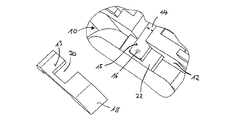
- ハウジングボディ(6)を有する質量流量センサ装置(2)を製造する方法であって、当該ハウジングボディ(6)はバイパス(10)を有しており、
・担体部材(22)を前記ハウジングボディ(6)および/または前記バイパス(10)の内壁部(12)に接着し、
・少なくとも1つのセンサ部材(16)を伴う質量流量センサ(14)を、通過して流れる空気質量を求めるために、少なくとも部分的にバイパス(10)内に配置し、前記担体部材(22)と機械的に次のように結合する、すなわち、少なくとも1つのセンサ部材(16)が、前記バイパス(10)内に、所定のポジションで配置されるように結合し、
・次に、切り欠き(20)を備えた流体内物体(18)を提供し、当該流体内物体は、少なくとも1つのセンサ部材(16)の領域においてフローガイドを設定するために構成されており、当該流体内物体を、前記担体部材(22)および/または前記バイパス(10)の内壁部(12)に、前記担体部材(22)を覆うように接着し、前記担体部材(22)および/またはハウジングボディ(6)と、前記質量流量センサ(14)が前記流体内物体(18)の切り欠き(20)内に配置されるように機械的に結合する、
ことを特徴とする、質量流量センサ装置を製造する方法。 - 前記質量流量センサ(14)を前記担体部材(22)上に接着する、請求項1記載の方法。
- 質量流量センサ装置(2)であって、
当該質量流量センサ装置は以下のものを有しており:すなわち、
・バイパス(10)を有しているハウジングボディ(6)と、
・前記ハウジングボディ(6)および/または前記バイパス(10)の内壁部(12)に接着されている担体部材(22)と、
・通過して流れる空気質量を求める少なくとも1つのセンサ部材(16)を有する質量流量センサ(14)とを有しており、当該質量流量センサは、少なくとも部分的に前記バイパス(10)内に配置されており、前記少なくとも1つのセンサ部材(16)が前記バイパス(10)内で所定の位置に配置されるように前記担体部材(22)と機械的に結合されており、
・切り欠き(20)を有する流体内物体(18)を有しており、当該流体内物体は少なくとも1つのセンサ部材(16)の領域においてフローガイドを設定するように構成されており、かつ前記流体内物体は前記担体部材(22)および/または前記バイパス(10)の内壁部(12)に、前記担体部材(22)を覆うように接着されており、前記担体部材(22)および/またはハウジングボディ(6)と、前記質量流量センサ(14)が前記流体内物体(18)の切り欠き(20)内に配置されるように機械的に結合されている、
ことを特徴とする質量流量センサ装置。 - 前記担体部材(22)はセラミックまたはプラスチックから構成されている、請求項3記載の質量流量センサ装置(2)。
- 前記バイパス(10)は、前記ハウジングボディ(6)内で、フローチャネル(8)から分岐しており、流れ方向において下流で再び前記フローチャネル(8)に合流する、請求項3または4記載の質量流量センサ装置(2)。
Applications Claiming Priority (2)
| Application Number | Priority Date | Filing Date | Title |
|---|---|---|---|
| DE102008052404.2 | 2008-10-21 | ||
| DE200810052404 DE102008052404B4 (de) | 2008-10-21 | 2008-10-21 | Verfahren zum Herstellen einer Massenstromsensorvorrichtung |
Publications (2)
| Publication Number | Publication Date |
|---|---|
| JP2010101889A JP2010101889A (ja) | 2010-05-06 |
| JP5634698B2 true JP5634698B2 (ja) | 2014-12-03 |
Family
ID=42054947
Family Applications (1)
| Application Number | Title | Priority Date | Filing Date |
|---|---|---|---|
| JP2009241623A Expired - Fee Related JP5634698B2 (ja) | 2008-10-21 | 2009-10-20 | 質量流量センサ装置の製造方法および質量流量センサ装置 |
Country Status (2)
| Country | Link |
|---|---|
| JP (1) | JP5634698B2 (ja) |
| DE (1) | DE102008052404B4 (ja) |
Families Citing this family (4)
| Publication number | Priority date | Publication date | Assignee | Title |
|---|---|---|---|---|
| CN104964721B (zh) * | 2015-06-30 | 2017-12-05 | 蔡丰勇 | 空气流量计的气体流道结构 |
| DE112019000709T5 (de) | 2018-02-07 | 2020-11-05 | Denso Corporation | Vorrichtung zur Messung einer physikalischen Größe |
| JP2020106428A (ja) * | 2018-12-27 | 2020-07-09 | 株式会社デンソー | 物理量計測装置 |
| JP2019138707A (ja) | 2018-02-07 | 2019-08-22 | 株式会社デンソー | 物理量計測装置 |
Family Cites Families (10)
| Publication number | Priority date | Publication date | Assignee | Title |
|---|---|---|---|---|
| DE4219454C2 (de) | 1992-06-13 | 1995-09-28 | Bosch Gmbh Robert | Massenflußsensor |
| JP2859831B2 (ja) * | 1995-05-25 | 1999-02-24 | 光照 木村 | フローセンサ、その製造方法および駆動方法 |
| JP3310167B2 (ja) | 1996-06-12 | 2002-07-29 | 株式会社ユニシアジェックス | 気体流量計測装置 |
| DE19744997A1 (de) * | 1997-10-11 | 1999-04-15 | Bosch Gmbh Robert | Vorrichtung zur Messung der Masse eines strömenden Mediums |
| JP3587734B2 (ja) * | 1999-06-30 | 2004-11-10 | 株式会社日立製作所 | 熱式空気流量センサ |
| DE19939824A1 (de) * | 1999-08-21 | 2001-02-22 | Bosch Gmbh Robert | Vorrichtung zur Messung der Masse eines strömenden Mediums |
| JP4106224B2 (ja) | 2002-03-14 | 2008-06-25 | 株式会社デンソー | 流量測定装置 |
| JP2006047272A (ja) * | 2004-06-29 | 2006-02-16 | Ngk Spark Plug Co Ltd | 流量センサ |
| DE102005036189A1 (de) | 2005-08-02 | 2007-02-08 | Robert Bosch Gmbh | Verfahren zur Herstellung eines Heißfilmluftmassenmessers |
| DE102007024865A1 (de) * | 2007-05-29 | 2008-12-04 | Robert Bosch Gmbh | Vorrichtung zur Bestimmung wenigstens eines Parameters eines fluiden Mediums |
-
2008
- 2008-10-21 DE DE200810052404 patent/DE102008052404B4/de not_active Expired - Fee Related
-
2009
- 2009-10-20 JP JP2009241623A patent/JP5634698B2/ja not_active Expired - Fee Related
Also Published As
| Publication number | Publication date |
|---|---|
| JP2010101889A (ja) | 2010-05-06 |
| DE102008052404B4 (de) | 2014-05-28 |
| DE102008052404A1 (de) | 2010-04-29 |
Similar Documents
| Publication | Publication Date | Title |
|---|---|---|
| US8215160B2 (en) | Sensor structure | |
| JP5396410B2 (ja) | センサの構造 | |
| US8701475B2 (en) | Air flow measuring device | |
| CN104081169B (zh) | 流量计测装置 | |
| KR101957133B1 (ko) | 유체의 유동 특성을 검출하기 위한 센서 장치 | |
| CN105324644B (zh) | 物理量测量装置 | |
| JP4416012B2 (ja) | 吸入空気流量測定装置 | |
| CN106662476B (zh) | 物理量检测装置 | |
| CN106415213B (zh) | 用于确定流过通道结构的流体介质的至少一个参数的传感器装置 | |
| JP6689387B2 (ja) | エアフローメータ | |
| CN107607164B (zh) | 热式流量计 | |
| JP2009541757A (ja) | 排気管内の層抵抗体 | |
| JP5634698B2 (ja) | 質量流量センサ装置の製造方法および質量流量センサ装置 | |
| JP4755712B2 (ja) | 質量流量センサ装置 | |
| KR101768736B1 (ko) | 공기 질량 계측기 | |
| JP4707412B2 (ja) | 気体流量測定装置 | |
| JP2015087196A (ja) | 温湿度センサ用ヒータの温度制御装置 | |
| US6571623B1 (en) | Measuring instrument with rectangular flow channel and sensors for measuring the mass of a flowing medium | |
| JP2012242298A (ja) | 流量検出装置 | |
| KR20080015926A (ko) | 유량 센서 | |
| JP5542614B2 (ja) | 流量測定装置 | |
| CN106969790B (zh) | 用于感测流体介质的至少一个流动特性的传感器装置 | |
| CN110741232A (zh) | 用于感测流体介质的至少一个特性的传感器 | |
| CN105319326B (zh) | 确定流过测量通道的流体介质的至少一个参数的传感器 | |
| KR20150070389A (ko) | 공기 질량 센서 |
Legal Events
| Date | Code | Title | Description |
|---|---|---|---|
| RD04 | Notification of resignation of power of attorney |
Free format text: JAPANESE INTERMEDIATE CODE: A7424 Effective date: 20101228 |
|
| A621 | Written request for application examination |
Free format text: JAPANESE INTERMEDIATE CODE: A621 Effective date: 20120827 |
|
| RD02 | Notification of acceptance of power of attorney |
Free format text: JAPANESE INTERMEDIATE CODE: A7422 Effective date: 20120827 |
|
| A131 | Notification of reasons for refusal |
Free format text: JAPANESE INTERMEDIATE CODE: A131 Effective date: 20131125 |
|
| A521 | Request for written amendment filed |
Free format text: JAPANESE INTERMEDIATE CODE: A523 Effective date: 20140220 |
|
| TRDD | Decision of grant or rejection written | ||
| A01 | Written decision to grant a patent or to grant a registration (utility model) |
Free format text: JAPANESE INTERMEDIATE CODE: A01 Effective date: 20140916 |
|
| A61 | First payment of annual fees (during grant procedure) |
Free format text: JAPANESE INTERMEDIATE CODE: A61 Effective date: 20141015 |
|
| R150 | Certificate of patent or registration of utility model |
Ref document number: 5634698 Country of ref document: JP Free format text: JAPANESE INTERMEDIATE CODE: R150 |
|
| R250 | Receipt of annual fees |
Free format text: JAPANESE INTERMEDIATE CODE: R250 |
|
| R250 | Receipt of annual fees |
Free format text: JAPANESE INTERMEDIATE CODE: R250 |
|
| R250 | Receipt of annual fees |
Free format text: JAPANESE INTERMEDIATE CODE: R250 |
|
| R250 | Receipt of annual fees |
Free format text: JAPANESE INTERMEDIATE CODE: R250 |
|
| R250 | Receipt of annual fees |
Free format text: JAPANESE INTERMEDIATE CODE: R250 |
|
| R250 | Receipt of annual fees |
Free format text: JAPANESE INTERMEDIATE CODE: R250 |
|
| S111 | Request for change of ownership or part of ownership |
Free format text: JAPANESE INTERMEDIATE CODE: R313113 |
|
| R360 | Written notification for declining of transfer of rights |
Free format text: JAPANESE INTERMEDIATE CODE: R360 |
|
| R360 | Written notification for declining of transfer of rights |
Free format text: JAPANESE INTERMEDIATE CODE: R360 |
|
| R371 | Transfer withdrawn |
Free format text: JAPANESE INTERMEDIATE CODE: R371 |
|
| S111 | Request for change of ownership or part of ownership |
Free format text: JAPANESE INTERMEDIATE CODE: R313113 |
|
| R350 | Written notification of registration of transfer |
Free format text: JAPANESE INTERMEDIATE CODE: R350 |
|
| LAPS | Cancellation because of no payment of annual fees |