JP5627698B2 - Imaging system and technique - Google Patents
Imaging system and technique Download PDFInfo
- Publication number
- JP5627698B2 JP5627698B2 JP2012534178A JP2012534178A JP5627698B2 JP 5627698 B2 JP5627698 B2 JP 5627698B2 JP 2012534178 A JP2012534178 A JP 2012534178A JP 2012534178 A JP2012534178 A JP 2012534178A JP 5627698 B2 JP5627698 B2 JP 5627698B2
- Authority
- JP
- Japan
- Prior art keywords
- slide
- focus
- stage
- dither
- lens
- Prior art date
- Legal status (The legal status is an assumption and is not a legal conclusion. Google has not performed a legal analysis and makes no representation as to the accuracy of the status listed.)
- Expired - Fee Related
Links
- 238000000034 method Methods 0.000 title claims description 149
- 238000003384 imaging method Methods 0.000 title description 114
- 230000033001 locomotion Effects 0.000 claims description 101
- 238000012360 testing method Methods 0.000 claims description 21
- 238000013519 translation Methods 0.000 claims description 17
- 238000005259 measurement Methods 0.000 claims description 9
- 238000005452 bending Methods 0.000 claims description 8
- 238000010586 diagram Methods 0.000 description 95
- 238000012545 processing Methods 0.000 description 81
- 210000001519 tissue Anatomy 0.000 description 69
- 230000008569 process Effects 0.000 description 55
- 230000006870 function Effects 0.000 description 31
- 238000005286 illumination Methods 0.000 description 31
- 230000003287 optical effect Effects 0.000 description 23
- 239000002131 composite material Substances 0.000 description 20
- 239000011521 glass Substances 0.000 description 19
- 238000004364 calculation method Methods 0.000 description 16
- 210000003128 head Anatomy 0.000 description 14
- 230000007170 pathology Effects 0.000 description 13
- 239000004033 plastic Substances 0.000 description 10
- 230000004044 response Effects 0.000 description 8
- 239000000523 sample Substances 0.000 description 8
- 230000007704 transition Effects 0.000 description 6
- 241000276498 Pollachius virens Species 0.000 description 5
- 230000008859 change Effects 0.000 description 5
- 238000013461 design Methods 0.000 description 5
- 238000000386 microscopy Methods 0.000 description 5
- 230000008901 benefit Effects 0.000 description 4
- 210000004027 cell Anatomy 0.000 description 4
- 230000007246 mechanism Effects 0.000 description 4
- 239000005357 flat glass Substances 0.000 description 3
- 239000000463 material Substances 0.000 description 3
- 230000001575 pathological effect Effects 0.000 description 3
- 230000003134 recirculating effect Effects 0.000 description 3
- 230000032258 transport Effects 0.000 description 3
- 229910000831 Steel Inorganic materials 0.000 description 2
- 230000001133 acceleration Effects 0.000 description 2
- 238000004458 analytical method Methods 0.000 description 2
- 238000013459 approach Methods 0.000 description 2
- 230000000295 complement effect Effects 0.000 description 2
- 238000004624 confocal microscopy Methods 0.000 description 2
- 238000005516 engineering process Methods 0.000 description 2
- 230000005484 gravity Effects 0.000 description 2
- 238000007373 indentation Methods 0.000 description 2
- 238000007689 inspection Methods 0.000 description 2
- 238000012544 monitoring process Methods 0.000 description 2
- 210000001747 pupil Anatomy 0.000 description 2
- 230000005855 radiation Effects 0.000 description 2
- 230000009467 reduction Effects 0.000 description 2
- 238000005070 sampling Methods 0.000 description 2
- 239000004065 semiconductor Substances 0.000 description 2
- 239000010959 steel Substances 0.000 description 2
- 230000001360 synchronised effect Effects 0.000 description 2
- 230000001960 triggered effect Effects 0.000 description 2
- 238000004804 winding Methods 0.000 description 2
- 238000002965 ELISA Methods 0.000 description 1
- 239000004593 Epoxy Substances 0.000 description 1
- 229910000760 Hardened steel Inorganic materials 0.000 description 1
- 229910000639 Spring steel Inorganic materials 0.000 description 1
- 239000006094 Zerodur Substances 0.000 description 1
- 230000005856 abnormality Effects 0.000 description 1
- 210000004102 animal cell Anatomy 0.000 description 1
- 238000000339 bright-field microscopy Methods 0.000 description 1
- 238000004113 cell culture Methods 0.000 description 1
- 210000003850 cellular structure Anatomy 0.000 description 1
- 210000000349 chromosome Anatomy 0.000 description 1
- 150000001875 compounds Chemical class 0.000 description 1
- 238000007796 conventional method Methods 0.000 description 1
- 238000012937 correction Methods 0.000 description 1
- 230000008878 coupling Effects 0.000 description 1
- 238000010168 coupling process Methods 0.000 description 1
- 238000005859 coupling reaction Methods 0.000 description 1
- 238000003745 diagnosis Methods 0.000 description 1
- 201000010099 disease Diseases 0.000 description 1
- 208000037265 diseases, disorders, signs and symptoms Diseases 0.000 description 1
- 238000007876 drug discovery Methods 0.000 description 1
- 238000013213 extrapolation Methods 0.000 description 1
- 238000010166 immunofluorescence Methods 0.000 description 1
- 230000003993 interaction Effects 0.000 description 1
- 238000011545 laboratory measurement Methods 0.000 description 1
- 238000010859 live-cell imaging Methods 0.000 description 1
- 239000003879 lubricant additive Substances 0.000 description 1
- 239000010687 lubricating oil Substances 0.000 description 1
- 238000012423 maintenance Methods 0.000 description 1
- 229910044991 metal oxide Inorganic materials 0.000 description 1
- 150000004706 metal oxides Chemical class 0.000 description 1
- 239000000203 mixture Substances 0.000 description 1
- 230000000737 periodic effect Effects 0.000 description 1
- 238000002135 phase contrast microscopy Methods 0.000 description 1
- 238000004161 plant tissue culture Methods 0.000 description 1
- 238000005498 polishing Methods 0.000 description 1
- 239000004810 polytetrafluoroethylene Substances 0.000 description 1
- 229920001343 polytetrafluoroethylene Polymers 0.000 description 1
- 230000003252 repetitive effect Effects 0.000 description 1
- 230000000717 retained effect Effects 0.000 description 1
- 238000004904 shortening Methods 0.000 description 1
- 229910001220 stainless steel Inorganic materials 0.000 description 1
- 239000010935 stainless steel Substances 0.000 description 1
- 229920001169 thermoplastic Polymers 0.000 description 1
- 239000012815 thermoplastic material Substances 0.000 description 1
- 239000004416 thermosoftening plastic Substances 0.000 description 1
- 230000002103 transcriptional effect Effects 0.000 description 1
- 238000012546 transfer Methods 0.000 description 1
Images


Classifications
-
- G—PHYSICS
- G02—OPTICS
- G02B—OPTICAL ELEMENTS, SYSTEMS OR APPARATUS
- G02B21/00—Microscopes
- G02B21/36—Microscopes arranged for photographic purposes or projection purposes or digital imaging or video purposes including associated control and data processing arrangements
-
- G—PHYSICS
- G02—OPTICS
- G02B—OPTICAL ELEMENTS, SYSTEMS OR APPARATUS
- G02B21/00—Microscopes
- G02B21/0004—Microscopes specially adapted for specific applications
- G02B21/002—Scanning microscopes
- G02B21/0024—Confocal scanning microscopes (CSOMs) or confocal "macroscopes"; Accessories which are not restricted to use with CSOMs, e.g. sample holders
- G02B21/0036—Scanning details, e.g. scanning stages
-
- G—PHYSICS
- G02—OPTICS
- G02B—OPTICAL ELEMENTS, SYSTEMS OR APPARATUS
- G02B17/00—Systems with reflecting surfaces, with or without refracting elements
- G02B17/08—Catadioptric systems
-
- G—PHYSICS
- G02—OPTICS
- G02B—OPTICAL ELEMENTS, SYSTEMS OR APPARATUS
- G02B21/00—Microscopes
- G02B21/0004—Microscopes specially adapted for specific applications
- G02B21/002—Scanning microscopes
-
- G—PHYSICS
- G02—OPTICS
- G02B—OPTICAL ELEMENTS, SYSTEMS OR APPARATUS
- G02B21/00—Microscopes
- G02B21/0004—Microscopes specially adapted for specific applications
- G02B21/002—Scanning microscopes
- G02B21/0024—Confocal scanning microscopes (CSOMs) or confocal "macroscopes"; Accessories which are not restricted to use with CSOMs, e.g. sample holders
- G02B21/0052—Optical details of the image generation
- G02B21/006—Optical details of the image generation focusing arrangements; selection of the plane to be imaged
-
- G—PHYSICS
- G02—OPTICS
- G02B—OPTICAL ELEMENTS, SYSTEMS OR APPARATUS
- G02B21/00—Microscopes
- G02B21/24—Base structure
- G02B21/241—Devices for focusing
- G02B21/245—Devices for focusing using auxiliary sources, detectors
-
- G—PHYSICS
- G02—OPTICS
- G02B—OPTICAL ELEMENTS, SYSTEMS OR APPARATUS
- G02B21/00—Microscopes
- G02B21/24—Base structure
- G02B21/26—Stages; Adjusting means therefor
-
- G—PHYSICS
- G02—OPTICS
- G02B—OPTICAL ELEMENTS, SYSTEMS OR APPARATUS
- G02B21/00—Microscopes
- G02B21/36—Microscopes arranged for photographic purposes or projection purposes or digital imaging or video purposes including associated control and data processing arrangements
- G02B21/361—Optical details, e.g. image relay to the camera or image sensor
-
- G—PHYSICS
- G02—OPTICS
- G02B—OPTICAL ELEMENTS, SYSTEMS OR APPARATUS
- G02B27/00—Optical systems or apparatus not provided for by any of the groups G02B1/00 - G02B26/00, G02B30/00
- G02B27/02—Viewing or reading apparatus
-
- G—PHYSICS
- G01—MEASURING; TESTING
- G01N—INVESTIGATING OR ANALYSING MATERIALS BY DETERMINING THEIR CHEMICAL OR PHYSICAL PROPERTIES
- G01N1/00—Sampling; Preparing specimens for investigation
- G01N1/28—Preparing specimens for investigation including physical details of (bio-)chemical methods covered elsewhere, e.g. G01N33/50, C12Q
- G01N1/30—Staining; Impregnating ; Fixation; Dehydration; Multistep processes for preparing samples of tissue, cell or nucleic acid material and the like for analysis
- G01N1/31—Apparatus therefor
- G01N1/312—Apparatus therefor for samples mounted on planar substrates
-
- G—PHYSICS
- G01—MEASURING; TESTING
- G01N—INVESTIGATING OR ANALYSING MATERIALS BY DETERMINING THEIR CHEMICAL OR PHYSICAL PROPERTIES
- G01N35/00—Automatic analysis not limited to methods or materials provided for in any single one of groups G01N1/00 - G01N33/00; Handling materials therefor
- G01N35/00029—Automatic analysis not limited to methods or materials provided for in any single one of groups G01N1/00 - G01N33/00; Handling materials therefor provided with flat sample substrates, e.g. slides
- G01N2035/00039—Transport arrangements specific to flat sample substrates, e.g. pusher blade
- G01N2035/00049—Transport arrangements specific to flat sample substrates, e.g. pusher blade for loading/unloading a carousel
-
- G—PHYSICS
- G01—MEASURING; TESTING
- G01N—INVESTIGATING OR ANALYSING MATERIALS BY DETERMINING THEIR CHEMICAL OR PHYSICAL PROPERTIES
- G01N35/00—Automatic analysis not limited to methods or materials provided for in any single one of groups G01N1/00 - G01N33/00; Handling materials therefor
- G01N35/00029—Automatic analysis not limited to methods or materials provided for in any single one of groups G01N1/00 - G01N33/00; Handling materials therefor provided with flat sample substrates, e.g. slides
- G01N2035/00099—Characterised by type of test elements
- G01N2035/00138—Slides
-
- G—PHYSICS
- G01—MEASURING; TESTING
- G01N—INVESTIGATING OR ANALYSING MATERIALS BY DETERMINING THEIR CHEMICAL OR PHYSICAL PROPERTIES
- G01N35/00—Automatic analysis not limited to methods or materials provided for in any single one of groups G01N1/00 - G01N33/00; Handling materials therefor
- G01N35/02—Automatic analysis not limited to methods or materials provided for in any single one of groups G01N1/00 - G01N33/00; Handling materials therefor using a plurality of sample containers moved by a conveyor system past one or more treatment or analysis stations
- G01N35/04—Details of the conveyor system
- G01N2035/0439—Rotary sample carriers, i.e. carousels
- G01N2035/0441—Rotary sample carriers, i.e. carousels for samples
-
- G—PHYSICS
- G01—MEASURING; TESTING
- G01N—INVESTIGATING OR ANALYSING MATERIALS BY DETERMINING THEIR CHEMICAL OR PHYSICAL PROPERTIES
- G01N35/00—Automatic analysis not limited to methods or materials provided for in any single one of groups G01N1/00 - G01N33/00; Handling materials therefor
- G01N35/02—Automatic analysis not limited to methods or materials provided for in any single one of groups G01N1/00 - G01N33/00; Handling materials therefor using a plurality of sample containers moved by a conveyor system past one or more treatment or analysis stations
- G01N35/04—Details of the conveyor system
- G01N2035/046—General conveyor features
- G01N2035/0462—Buffers [FIFO] or stacks [LIFO] for holding carriers between operations
-
- G—PHYSICS
- G01—MEASURING; TESTING
- G01N—INVESTIGATING OR ANALYSING MATERIALS BY DETERMINING THEIR CHEMICAL OR PHYSICAL PROPERTIES
- G01N35/00—Automatic analysis not limited to methods or materials provided for in any single one of groups G01N1/00 - G01N33/00; Handling materials therefor
- G01N35/02—Automatic analysis not limited to methods or materials provided for in any single one of groups G01N1/00 - G01N33/00; Handling materials therefor using a plurality of sample containers moved by a conveyor system past one or more treatment or analysis stations
- G01N35/04—Details of the conveyor system
- G01N2035/0474—Details of actuating means for conveyors or pipettes
- G01N2035/0491—Position sensing, encoding; closed-loop control
- G01N2035/0493—Locating samples; identifying different tube sizes
-
- G—PHYSICS
- G01—MEASURING; TESTING
- G01N—INVESTIGATING OR ANALYSING MATERIALS BY DETERMINING THEIR CHEMICAL OR PHYSICAL PROPERTIES
- G01N35/00—Automatic analysis not limited to methods or materials provided for in any single one of groups G01N1/00 - G01N33/00; Handling materials therefor
- G01N35/0099—Automatic analysis not limited to methods or materials provided for in any single one of groups G01N1/00 - G01N33/00; Handling materials therefor comprising robots or similar manipulators
Description
本願は、「On−the−Fly Focusing Sensor」という名称の2010年7月23日出願の米国特許仮出願第61/367,341号、「Slide Caching in a Slide Scanning Microscope」という名称の2010年1月28日出願の米国特許仮出願第61/299,231号、「Scanning Microscope Slide Stage」という名称の2009年11月13日出願の米国特許仮出願第61/261,251号、「High Speed Slide Scanning System for Digital Pathology」という名称の2009年10月29日出願の米国特許仮出願第61/256,228号、および「On−the−Fly Focusing Systems and Techniques for Scanning Microscopes」という名称の2009年10月19日出願の米国特許仮出願第61/252,995号に対する優先権を主張する。同願をすべて、参照により本明細書に組み込む。 This application is based on US Patent Provisional Application No. 61 / 367,341, filed July 23, 2010, entitled “On-the-Fly Focusing Sensor”, 2010 1 named “Slide Caching in a Slide Scanning Microscope”. US Provisional Application No. 61 / 299,231 filed on May 28, US Patent Provisional Application No. 61 / 261,251 filed on November 13, 2009 entitled “Scanning Microscope Slide Stage”, “High Speed Slide” US Provisional Application No. 61 / 256,228, filed Oct. 29, 2009, entitled “Scanning System for Digital Pathology”, and “On-the-Fly”. Claims priority to US Provisional Application No. 61 / 252,995, filed Oct. 19, 2009, entitled “Focusing Systems and Technologies for Scanning Microscopes”. All of that application is incorporated herein by reference.
本願は、撮像の分野に関し、より詳細には、画像を取得および捕獲するシステムおよび技法に関する。 The present application relates to the field of imaging, and more particularly to systems and techniques for acquiring and capturing images.
疾病を示す細胞構造の変化の分子撮像識別は、依然として、創薬科学をよりよく理解するための鍵である。顕微鏡検査の適用分野は、微生物学(たとえば、グラム染色など)、植物組織培養、動物細胞培養(たとえば、位相差顕微鏡検査など)、分子生物学、免疫学(たとえば、ELISAなど)、細胞生物学(たとえば、免疫蛍光法、染色体分析など)、共焦点顕微鏡検査、微速度および生細胞撮像、直列および3次元撮像に適用することができる。 Molecular imaging discrimination of changes in cellular structure indicative of disease remains the key to a better understanding of drug discovery science. Microscopy applications include microbiology (eg, Gram stain), plant tissue culture, animal cell culture (eg, phase contrast microscopy), molecular biology, immunology (eg, ELISA), cell biology. (Eg, immunofluorescence, chromosome analysis, etc.), confocal microscopy, time-lapse and live cell imaging, serial and three-dimensional imaging.
共焦点顕微鏡検査の進歩により、細胞内で発生する秘密の多くを解明してきたため、蛍光マーカを使用すると、転写および並進のレベル変化を検出することができる。共焦点手法の利点は、試験片を通じて順次高い分解能で個々の光学断面を撮像する特性に起因する。しかし依然として、比較的低いコストで病理組織の正確な分析を提供する病理組織の画像のデジタル処理システムおよび方法が必要とされている。 Advances in confocal microscopy have uncovered many of the secrets that occur in cells, so fluorescent markers can be used to detect transcriptional and translational level changes. The advantage of the confocal technique is due to the property of imaging individual optical sections through the specimen with sequentially high resolution. However, there remains a need for digital processing systems and methods for pathological tissue images that provide accurate analysis of pathological tissue at a relatively low cost.
デジタル病理学における所望の目標は、観察するための高分解能のデジタル画像を短期間で取得することである。病理学者が顕微鏡の接眼レンズを通じてスライドを観察する現在の手動の方法では、細胞特性の検査または染色された細胞と染色されていない細胞の計数の際に診断することができる。デジタル画像が収集され、高分解能のモニタで観察され、また後の使用のために共用および保管できる自動化された方法が望ましい。デジタル化プロセスは、高い処理量ならびに高分解能および高品質の画像で効率的に実現されると有利である。 The desired goal in digital pathology is to acquire high resolution digital images for observation in a short period of time. Current manual methods in which a pathologist views a slide through a microscope eyepiece can make a diagnosis upon examination of cell characteristics or counting of stained and unstained cells. It is desirable to have an automated method in which digital images can be collected, viewed on a high resolution monitor, and shared and stored for later use. The digitization process is advantageously implemented efficiently with high throughput and high resolution and quality images.
従来の仮想顕微鏡検査システムにおける撮像技法では、個々の画像で、画像の大部分において著しく焦点がずれている可能性がある。従来の撮像システムは、カメラによって得られるそれぞれの個々のスナップショットに対して単一の焦点距離に制限されており、したがって、走査されている対象試験片の表面が均一でないとき、それぞれの「視野」には焦点のずれた領域がある。仮想顕微鏡検査で用いられる高倍率レベルでは、均一の表面を有する試験片は極めてまれである。 With imaging techniques in conventional virtual microscopy systems, individual images can be significantly out of focus in the majority of the image. Conventional imaging systems are limited to a single focal length for each individual snapshot taken by the camera, and therefore each “field of view” when the surface of the target specimen being scanned is not uniform. "Has a region out of focus. At high magnification levels used in virtual microscopy, specimens with a uniform surface are extremely rare.
従来のシステムは、1)第1の通過において、組織断面の上部に配置された2次元の格子上に構成された画像フレームによって分離される点のアレイで最善の焦点を判定するステップと、2)別の通過において、各焦点へ移動して画像フレームを獲得するステップとを含む2ステッププロセスに基づく事前集束技法を使用して、高い比率の焦点ずれ画像に対処する。これらの最善の焦点間の点では、焦点は補間される。この2ステッププロセスは、焦点ずれ画像を低減させ、またはさらにはなくすことができるが、このプロセスの結果、傾けた画像を獲得する速度が著しく損失される。 Conventional systems include 1) determining the best focus in an array of points separated by image frames constructed on a two-dimensional grid placed on top of the tissue cross section in the first pass; In a different pass, a high-focus defocused image is addressed using a pre-focusing technique based on a two-step process that includes moving to each focus and acquiring an image frame. At the point between these best focus points, the focus points are interpolated. This two-step process can reduce or even eliminate defocused images, but as a result of this process, the speed of acquiring tilted images is significantly lost.
したがって、従来の撮像システムに固有の著しい問題を克服し、焦点の合った高品質の画像を高い処理量で効率的に提供するシステムを提供することが望ましいであろう。 Therefore, it would be desirable to provide a system that overcomes the significant problems inherent in conventional imaging systems and that efficiently provides high quality images with high focus and high throughput.
本明細書に記載するシステムによれば、試験片の焦点の合った画像を取得するデバイスは、試験片を検査するように配置された対物レンズを含む。対物レンズには低速集束ステージが結合され、低速集束ステージは、対物レンズの移動を制御する。ディザ焦点ステージがディザレンズを含み、ディザ焦点ステージはディザレンズを移動させる。ディザレンズを介して伝送される光に従って、焦点センサが焦点情報を提供する。少なくとも1つの電気構成要素が焦点情報を使用して測定基準を判定し、測定基準に従って対物レンズの第1の焦点位置を判定し、電気構成要素は、対物レンズを第1の焦点位置へ移動させるための位置情報を低速集束ステージへ送る。対物レンズが第1の焦点位置へ移動された後、画像センサが試験片の画像を捕獲する。XY移動ステージを含むことができ、XY移動ステージ上に試験片が配置され、電気構成要素は、XY移動ステージの移動を制御する。XY移動ステージの移動は、ディザレンズの運動に位相ロックすることができる。ディザ焦点ステージは、ディザレンズを並進運動で移動させる音声コイル作動式の屈曲アセンブリを含むことができる。ディザレンズは、少なくとも60Hzの共振周波数で移動させることができ、電気構成要素は、焦点情報を使用して、1秒当たり少なくとも60回の焦点計算を実行する。焦点センサおよびディザ焦点ステージは、双方向に動作するように設定することができ、焦点センサは、共振周波数のディザレンズの運動の正弦波形の上下部分両方に関する焦点情報を生成する。測定基準は、コントラスト情報、鮮明度情報、および/または色度情報を含むことができる。焦点情報は、試験片の焦点走査中に使用される焦点窓の複数の区間に対する情報を含むことができる。電気構成要素は、XY移動ステージの移動を制御することができ、XY移動ステージの速度を判定する際に、複数の区間の少なくとも一部分からの情報が使用される。焦点センサの視野は、画像センサの視野に対して傾けることができる。 In accordance with the system described herein, a device for acquiring a focused image of a test strip includes an objective lens arranged to inspect the test strip. A slow focusing stage is coupled to the objective lens, and the slow focusing stage controls the movement of the objective lens. The dither focus stage includes a dither lens, and the dither focus stage moves the dither lens. A focus sensor provides focus information according to the light transmitted through the dither lens. At least one electrical component uses the focus information to determine a metric, and determines a first focus position of the objective according to the metric, and the electrical component moves the objective to the first focus position. Position information is sent to the low-speed focusing stage. After the objective lens is moved to the first focal position, the image sensor captures an image of the specimen. An XY moving stage can be included, a test piece is disposed on the XY moving stage, and the electrical components control the movement of the XY moving stage. The movement of the XY moving stage can be phase locked to the movement of the dither lens. The dither focus stage may include a voice coil actuated bending assembly that moves the dither lens in translation. The dither lens can be moved at a resonant frequency of at least 60 Hz, and the electrical component performs at least 60 focus calculations per second using the focus information. The focus sensor and dither focus stage can be set to operate in both directions, and the focus sensor generates focus information for both the upper and lower portions of the sinusoidal waveform of the dither lens motion at the resonant frequency. The metric can include contrast information, definition information, and / or chromaticity information. The focus information can include information for multiple sections of the focus window used during the focus scan of the specimen. The electrical component can control the movement of the XY moving stage, and information from at least a portion of the plurality of sections is used in determining the speed of the XY moving stage. The field of view of the focus sensor can be tilted with respect to the field of view of the image sensor.
さらに本明細書に記載するシステムによれば、試験片の焦点の合った画像を取得する方法が提供される。この方法は、試験片を検査するように配置された対物レンズの移動を制御するステップを含む。ディザレンズの運動が制御され、ディザレンズを介して伝送される光に従って焦点情報が提供される。焦点情報を使用して測定基準を判定し、測定基準に従って対物レンズの第1の焦点位置を判定する。対物レンズを第1の焦点位置へ移動させるために使用される位置情報が送られる。第1の焦点位置は、最善の焦点位置として判定することができ、この方法は、対物レンズが最善の焦点位置へ移動された後に、試験片の画像を捕獲するステップをさらに含むことができる。ディザレンズは、少なくとも60Hzの共振周波数で移動させることができ、1秒当たり少なくとも60回の焦点計算を実行することができる。測定基準は、鮮明度情報、コントラスト情報、および/または色度情報を含むことができる。焦点情報は、試験片の焦点走査中に使用される焦点窓の複数の区間に対する情報を含むことができる。試験片が配置されたXY移動ステージの移動を制御することができ、XY移動ステージの速度を判定する際に、複数の区間の少なくとも一部分からの情報を使用することができる。XY移動ステージの移動を制御して、試験片の前後の並進走査を提供することができる。 Furthermore, the system described herein provides a method for acquiring a focused image of a specimen. The method includes controlling the movement of an objective lens arranged to inspect the specimen. The movement of the dither lens is controlled and focus information is provided according to the light transmitted through the dither lens. The focus information is used to determine a measurement standard, and the first focus position of the objective lens is determined according to the measurement standard. Position information used to move the objective lens to the first focal position is sent. The first focus position can be determined as the best focus position, and the method can further include capturing an image of the specimen after the objective lens is moved to the best focus position. The dither lens can be moved at a resonant frequency of at least 60 Hz and can perform at least 60 focus calculations per second. The metric can include sharpness information, contrast information, and / or chromaticity information. The focus information can include information for multiple sections of the focus window used during the focus scan of the specimen. The movement of the XY moving stage on which the test piece is arranged can be controlled, and information from at least a part of the plurality of sections can be used when determining the speed of the XY moving stage. The movement of the XY translation stage can be controlled to provide translational scanning before and after the specimen.
さらに本明細書に記載するシステムによれば、試験片の画像を取得する方法は、公称焦点面を確立するステップを含む。試験片は、関連するxおよびy座標を有する開始位置で位置決めされる。前記試験片を越える単一の横断で、第1の処理が実行される。第1の処理は、ディザレンズを使用して、複数の点のそれぞれに対して焦点位置を判定するステップと、前記焦点位置に従って、前記複数の点のそれぞれに対してフレームを獲得するステップとを含む。 Further in accordance with the system described herein, a method for obtaining an image of a specimen includes establishing a nominal focal plane. The specimen is positioned at a starting position with associated x and y coordinates. The first process is performed in a single traverse beyond the specimen. The first process includes a step of determining a focal position for each of a plurality of points using a dither lens, and a step of acquiring a frame for each of the plurality of points according to the focal position. Including.
さらに本明細書に記載するシステムによれば、コンピュータ可読媒体が、上述したステップのいずれかによって試験片の焦点の合った画像を取得するために記憶されたコードを備える。さらに、コンピュータ可読媒体は、後述するプロセスのいずれか1つまたは複数を実行するために記憶されたコードを備えることができる。 Further in accordance with the system described herein, a computer readable medium comprises code stored for obtaining a focused image of a test strip by any of the steps described above. Further, the computer readable medium can comprise stored code for performing any one or more of the processes described below.
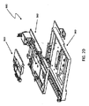
さらに本明細書に記載するシステムによれば、顕微鏡ステージのためのデバイスが、移動ステージブロックと、移動ステージブロックを案内する底ブロックとを含む。底ブロックは、実質上平坦な第1のブロックと、三角形の形状を有する第2のブロックとを含み、第1のブロックおよび第2のブロックは、移動ステージブロックを並進方向に案内する。第1のブロックおよび第2のブロックは、底板上の高くなった突起上で支持することができる。第1のブロックおよび第2のブロックは、ガラスから作製することができる。移動ステージブロック上に、第1のブロックおよび第2のブロックに接触する複数のボタン要素を配置することができ、ボタン要素は、並進方向にのみ移動ステージブロックの運動を可能にすることができる。ボタン要素は、球面形状を有することができ、熱可塑性物質から作製することができる。複数のボタン要素の少なくとも2つは、第2のブロックの三角形の形状の両側で互いに面するように構成することができ、複数のボタン要素の少なくとも1つのボタンは、その平坦な面で第1のブロックに接触する。移動ステージブロック上の複数のボタン要素の位置は、三角形を形成することができる。複数のボタン要素はそれぞれ、ステージの運動中に等しい重量を保持することができる。移動ステージブロックは、複数のボタン要素の位置によって形成された三角形の質量中心に重心を有するような形状とすることができる。片持ち梁アームアセンブリを提供することができ、片持ち梁アセンブリに堅く結合された第1の端部と、移動ステージブロック上の質量中心位置に結合された第2の端部とを有する屈曲要素を提供することができる。片持ち梁アームアセンブリは、レール上の再循環式の軸受設計を介して動作する軸受ブロックに結合された片持ち梁アームを含むことができる。レール上で軸受ブロックを駆動させると、屈曲要素は、移動ステージブロックに力を印加することができる。屈曲要素の曲げ剛性は、片持ち梁アームアセンブリの上下運動から移動ステージブロックを分離することができる。底ブロックは、移動ステージブロックの並進方向に対して垂直な方向に別の移動ステージを形成することができる。150ナノメートル程度の運動の繰返し精度を提供することができる。運動の繰返し精度は、移動ステージおよび底ブロックの並進方向に直交することができる。 Further in accordance with the system described herein, a device for a microscope stage includes a moving stage block and a bottom block that guides the moving stage block. The bottom block includes a substantially flat first block and a second block having a triangular shape, and the first block and the second block guide the moving stage block in the translational direction. The first block and the second block can be supported on raised protrusions on the bottom plate. The first block and the second block can be made from glass. A plurality of button elements that contact the first block and the second block may be disposed on the moving stage block, and the button elements may allow movement of the moving stage block only in the translational direction. The button element can have a spherical shape and can be made from a thermoplastic material. At least two of the plurality of button elements can be configured to face each other on both sides of the triangular shape of the second block, and at least one button of the plurality of button elements is first on its flat surface. Touch the block. The positions of the plurality of button elements on the moving stage block can form a triangle. Each of the plurality of button elements can hold an equal weight during stage movement. The moving stage block may have a shape having a center of gravity at the center of mass of a triangle formed by the positions of a plurality of button elements. A bending element that can provide a cantilever arm assembly and has a first end rigidly coupled to the cantilever assembly and a second end coupled to a center of mass position on the moving stage block Can be provided. The cantilever arm assembly can include a cantilever arm coupled to a bearing block that operates through a recirculating bearing design on the rail. When the bearing block is driven on the rail, the bending element can apply a force to the moving stage block. The bending stiffness of the bending element can separate the moving stage block from the up and down movement of the cantilever arm assembly. The bottom block can form another moving stage in a direction perpendicular to the translation direction of the moving stage block. It can provide motion repeatability on the order of 150 nanometers. The repeatability of the movement can be orthogonal to the translational direction of the moving stage and the bottom block.
さらに本明細書に記載するシステムによれば、スライドキャッシングのためのデバイスが、ラックと、バッファと、ラックとバッファの間で第1のスライドを移動させるスライドハンドラと、XYステージとを含む。XYステージは、第2のスライドの走査に関連して第2のスライドを移動させ、第1のスライドに対応するスライドハンドラの少なくとも1つの機能が、第2のスライドに対応するXYステージの少なくとも1つの機能と並行して実行される。スライドハンドラは、ラック、バッファ、およびXYステージの間で第1のスライドおよび第2のスライドを移動させることができ、少なくとも3自由度で移動することができる。XYステージは、バッファからXYステージへスライドを移動させるスライドピックアップヘッドを含むことができる。撮像デバイスが、第1のスライドおよび第2のスライドを撮像することができ、集束システムおよびカメラを含むことができる。集束システムは、動的集束システムを含むことができる。XYステージの機能と並行して実行されるスライドハンドラの機能は、少なくとも10%の時間利得を提供することができる。スライドハンドラは、機械的ピックアップデバイスおよび/または真空ピックアップデバイスを含むスライドピックアップヘッドを含むことができる。バッファは、複数のスライドを受け入れる複数のバッファ位置を含むことができる。バッファの少なくとも1つのバッファ位置は、スライドのサムネイル画像を捕獲するために使用される位置とすることができる。ラックは、少なくとも1つの主トレーおよび迂回トレーを含むことができ、主トレー内に何らかのスライドが配置される前に、迂回トレー内に配置されたスライドが処理される。 Further in accordance with the system described herein, a device for slide caching includes a rack, a buffer, a slide handler that moves a first slide between the rack and the buffer, and an XY stage. The XY stage moves the second slide in relation to the scanning of the second slide, and at least one function of the slide handler corresponding to the first slide is at least one of the XY stages corresponding to the second slide. Executed in parallel with one function. The slide handler can move the first slide and the second slide between the rack, the buffer, and the XY stage, and can move with at least three degrees of freedom. The XY stage can include a slide pickup head that moves the slide from the buffer to the XY stage. An imaging device can image the first slide and the second slide, and can include a focusing system and a camera. The focusing system can include a dynamic focusing system. A slide handler function executed in parallel with an XY stage function can provide a time gain of at least 10%. The slide handler can include a slide pickup head that includes a mechanical pickup device and / or a vacuum pickup device. The buffer may include a plurality of buffer positions that accept a plurality of slides. At least one buffer position of the buffer may be a position used to capture a thumbnail image of the slide. The rack can include at least one main tray and a bypass tray, and slides placed in the bypass tray are processed before any slides are placed in the main tray.
さらに本明細書に記載するシステムによれば、スライドキャッシングのための方法が、ラックおよびバッファを提供するステップを含む。ラックとバッファの間で、第1のスライドが移動される。第2のスライドが、第2のスライドの走査に関連してバッファ内またはバッファ外へ移動される。ラックとバッファの間の第1のスライドの移動は、第2のスライドの走査と並行して実行することができる。第2のスライドの走査は、集束動作および画像捕獲動作を含むことができる。第2のスライドの走査と並行して第1のスライドを移動させることで、少なくとも10%の時間利得を提供することができる。第2のスライドの走査は、動的集束動作を含むことができる。バッファは、カメラバッファ位置および戻りバッファ位置の少なくとも1つを含む複数のバッファ位置を含むことができる。この方法は、第1のスライドおよび/または第2のスライドがカメラバッファ位置にあるとき、第1のスライドおよび/または第2のスライドのサムネイル画像を捕獲するステップをさらに含むことができる。 Further in accordance with the system described herein, a method for slide caching includes providing a rack and a buffer. The first slide is moved between the rack and the buffer. The second slide is moved into or out of the buffer in connection with the scanning of the second slide. The movement of the first slide between the rack and the buffer can be performed in parallel with the scanning of the second slide. The scanning of the second slide can include a focusing operation and an image capture operation. Moving the first slide in parallel with the scanning of the second slide can provide a time gain of at least 10%. The scanning of the second slide can include a dynamic focusing operation. The buffer can include a plurality of buffer positions including at least one of a camera buffer position and a return buffer position. The method can further include capturing a thumbnail image of the first slide and / or the second slide when the first slide and / or the second slide is in the camera buffer position.
さらに本明細書に記載するシステムによれば、スライドキャッシングのためのデバイスは、第1のラック、第2のラック、第1のXYステージ、および第2のXYステージを含む。第1のXYステージは、第1のスライドを、第1のスライドの走査に関連して第1のラック内または第1のラック外へ移動させる。第2のXYステージは、第2のスライドを、第2のスライドの走査に関連して第2のラック内または第2のラック外へ移動させる。第1のスライドに対応する第1のXYステージの少なくとも1つの機能は、第2のスライドに対応する第2のXYステージの少なくとも1つの機能と並行して実行される。第1のラックおよび第2のラックは、単一のラックの一部を形成することができる。撮像デバイスが、第1のスライドおよび第2のスライドを撮像することができる。第1のXYステージと第2のXYステージはそれぞれ、スライドピックアップヘッドを含むことができる。 Further in accordance with the system described herein, a device for slide caching includes a first rack, a second rack, a first XY stage, and a second XY stage. The first XY stage moves the first slide in or out of the first rack in relation to the scanning of the first slide. The second XY stage moves the second slide in or out of the second rack in relation to the scanning of the second slide. At least one function of the first XY stage corresponding to the first slide is executed in parallel with at least one function of the second XY stage corresponding to the second slide. The first rack and the second rack can form part of a single rack. An imaging device can image the first slide and the second slide. Each of the first XY stage and the second XY stage can include a slide pickup head.
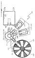
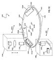
さらに本明細書に記載するシステムによれば、スライド走査のためのデバイスが、回転可能なトレーと、回転可能なトレー内に配置された少なくとも1つの凹部とを含む。凹部は、スライドを受け取るように寸法設定され、凹部は、回転可能なトレーの回転の結果、走査位置でスライドを安定させる。凹部は、スライドを安定させる複数の凸部を含むことができ、回転可能なトレーの円周リング上に配置された複数の凹部を含むことができる。撮像システムを含むことができ、撮像システムの少なくとも1つの構成要素は、回転可能なトレーの放射方向に移動する。撮像システムの構成要素は、回転可能なトレーの1回転に対応して放射方向に漸進的に移動することができる。凹部は、長さが幅より大きいスライドを受け取るように寸法設定することができ、スライドの長さは、回転可能なトレーの放射方向に向けることができる。凹部は、長さが幅より大きいスライドを受け取るように寸法設定することができ、スライドの幅は、回転可能なトレーの放射方向に向けることができる。 Further in accordance with the system described herein, a device for slide scanning includes a rotatable tray and at least one recess disposed in the rotatable tray. The recess is sized to receive the slide, and the recess stabilizes the slide at the scanning position as a result of rotation of the rotatable tray. The recess can include a plurality of protrusions that stabilize the slide, and can include a plurality of recesses disposed on the circumferential ring of the rotatable tray. An imaging system can be included, and at least one component of the imaging system moves in the radial direction of the rotatable tray. The components of the imaging system can move progressively in the radial direction corresponding to one rotation of the rotatable tray. The recess can be sized to receive a slide whose length is greater than the width, and the length of the slide can be directed in the radial direction of the rotatable tray. The recess can be sized to receive a slide whose length is greater than the width, and the width of the slide can be directed in the radial direction of the rotatable tray.
さらに本明細書に記載するシステムによれば、スライドを走査する方法が、回転可能なトレーの少なくとも1つの凹部内にスライドを配置するステップと、回転可能なトレーを回転させるステップとを含む。凹部は、スライドを受け取るように寸法設定され、凹部は、回転可能なトレーの回転の結果、走査位置でスライドを安定させる。凹部は、スライドを安定させる複数の凸部を含むことができ、回転可能なトレーの円周リング上に配置された複数の凹部を含むことができる。この方法は、撮像システムを提供するステップと、回転可能なトレーの放射方向に撮像システムの少なくとも1つの構成要素を移動させるステップとをさらに含むことができる。撮像システムの構成要素は、回転可能なトレーの1回転に対応して放射方向に漸進的に移動させることができる。凹部は、長さが幅より大きいスライドを受け取るように寸法設定することができ、スライドの長さは、回転可能なトレーの放射方向に向けられる。凹部は、長さが幅より大きいスライドを受け取るように寸法設定することができ、スライドの幅は、回転可能なトレーの放射方向に向けられる。 Further in accordance with the system described herein, a method for scanning a slide includes positioning the slide within at least one recess of the rotatable tray and rotating the rotatable tray. The recess is sized to receive the slide, and the recess stabilizes the slide at the scanning position as a result of rotation of the rotatable tray. The recess can include a plurality of protrusions that stabilize the slide, and can include a plurality of recesses disposed on the circumferential ring of the rotatable tray. The method can further include providing an imaging system and moving at least one component of the imaging system in the radial direction of the rotatable tray. The components of the imaging system can be moved progressively in the radial direction in response to one rotation of the rotatable tray. The recess can be sized to receive a slide whose length is greater than the width, the length of the slide being directed in the radial direction of the rotatable tray. The recess can be sized to receive a slide whose length is greater than the width, the width of the slide being directed in the radial direction of the rotatable tray.
本明細書に記載するシステムの実施形態について、図面に基づいて本明細書により詳細に説明する。図面について、以下に簡単に説明する。 Embodiments of the system described herein will be described in more detail herein with reference to the drawings. The drawings are briefly described below.
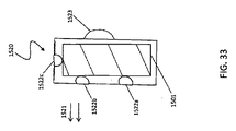
図35Bは、本明細書に記載するシステムの別の実施形態による回転式スライドホルダ上のスライドの代替構成を示す概略図である。
図1は、本明細書に記載するシステムの様々な実施形態によるデジタル病理学標本の走査および撮像に関連して使用される様々な構成要素デバイスを含むことができる走査顕微鏡および/または他の走査デバイスの撮像システム5の概略図である。撮像システム5は、本明細書に別途詳細にさらに論じるように、他の構成要素システム50の中でも、集束システム10、スライドステージシステム20、スライドキャッシングシステム30、および照射システム40を有する撮像デバイスを含むことができる。本明細書に記載するシステムは、「Digital Microscope Slide Scanning System and Methods」という名称のDietzらの米国特許出願公開第2008/0240613号に記載されているように、精度を実質的に損失することなく、拡大して画像を再構成し、再構成された画像を表示および記憶することに関連する特徴を含む、画像の捕獲、ステッチ、および拡大のための顕微鏡スライド走査計器のアーキテクチャおよび技法に関連して使用できることにも留意されたい。同願を、参照により本明細書に組み込む。
FIG. 1 illustrates a scanning microscope and / or other scanning that can include various component devices used in connection with scanning and imaging of digital pathology specimens according to various embodiments of the systems described herein. It is the schematic of the
図2は、本明細書に記載するシステムの一実施形態によるスライド上に配置された組織標本101および/または他の物体の焦点の合った画像を撮る集束システムの構成要素を含む光学走査顕微鏡および/または他の適当な撮像システムの撮像デバイス100を示す概略図である。本明細書に記載する集束システムは、スナップショットが捕獲されると、各スナップショットに対する最善の焦点の判定を実現する。これを、「実行中の集束」と呼ぶことができる。本明細書に提供されるデバイスおよび技法は、病理学スライド内の一領域のデジタル画像を形成するのに必要な時間を著しく低減させる。本明細書に記載するシステムは、従来のシステムの2ステップ手法のステップを組み込み、事前集束に必要な時間を本質的になくす。本明細書に記載するシステムは、スナップショットを捕獲するための実行中の処理を使用して顕微鏡スライド上の試験片のデジタル画像を作成するステップを提供し、すべてのスナップショットを捕獲する総時間は、スナップショットを捕獲する前に各スナップショットに対する焦点を事前判定するステップを使用する方法によって必要とされる時間より短くなる。
FIG. 2 illustrates an optical scanning microscope that includes components of a focusing system that takes a focused image of a tissue specimen 101 and / or other object placed on a slide according to one embodiment of the system described herein. FIG. 6 is a schematic diagram illustrating an
撮像デバイス100は、電荷結合デバイス(CCD)および/またはコンプリメンタリ(complimentary)金属酸化膜半導体(CMOS)画像センサなどの撮像センサ110を含むことができる。撮像センサ110は、デジタル病理学画像を捕獲するカメラ111の一部とすることができる。撮像センサ110は、光が伝送される顕微鏡の結像レンズ112、ビームスプリッタ114、ならびに集光器116および光源118および/または他の適当な光学構成要素119などの他の構成要素を介して、顕微鏡対物レンズ120から伝送される光を受け取ることができる。顕微鏡対物レンズ120は、無限大補正式とすることができる。一実施形態では、ビームスプリッタ114は、光ビーム源の約70%を画像センサ110へ誘導し、約30%の残りの部分を経路に沿ってディザ集束ステージ150および焦点センサ160へ誘導するように配分することを実現することができる。撮像されている組織標本101は、X方向およびY方向に移動できるXY移動ステージ130上に配置することができ、XY移動ステージ130は、本明細書に別途さらに論じるように制御することができる。低速集束ステージ140が、画像センサ110によって捕獲される組織101の画像を集束させるように、顕微鏡対物レンズ120のZ方向の移動を制御することができる。低速集束ステージ140は、顕微鏡対物レンズ120を移動させるモータおよび/または他の適したデバイスを含むことができる。本明細書に記載するシステムによれば、オンフライ(on−fly−)集束に対する微細な集束制御を提供するために、ディザ集束ステージ150および焦点センサ160が使用される。様々な実施形態では、焦点センサ160は、CCDおよび/またはCMOSセンサとすることができる。
The
ディザ集束ステージ150および焦点センサ160は、画像スナップショットが捕獲されると、各画像スナップショットに対する最善の焦点を取得するために撮像プロセス中に急速に計算される鮮明度値および/または他の測定基準に従って、実行中の集束を提供する。本明細書に別途詳細にさらに論じるように、ディザ集束ステージ150は、顕微鏡対物レンズ120のより低速の運動で実行可能な移動周波数とは無関係に、それを超過する周波数で、たとえば正弦運動で移動させることができる。焦点センサ160によって、ディザ集束ステージ150の運動範囲にわたって、組織の観察のための焦点情報に関する複数の測定が行われる。焦点電子機器および制御システム170は、焦点センサおよびディザリング焦点ステージ150を制御する電子機器と、マスタクロックと、低速焦点ステージ140を制御(Z方向)する電子機器と、X−Y移動ステージ130と、本明細書の技法によるシステムの一実施形態の他の構成要素とを含むことができる。焦点電子機器および制御システム170は、ディザ集束ステージ150および焦点センサ160からの情報を使用して鮮明度計算を実行するために使用することができる。ディザ移動によって画定される正弦曲線の少なくとも一部分にわたって、鮮明度値を計算することができる。次いで、焦点電子機器および制御システム170は、その情報を使用して組織の最善の焦点画像に対する位置を判定し、低速焦点ステージ140に命令して、撮像プロセス中に最善の焦点画像を取得するのに所望の位置へ顕微鏡対物レンズ120を移動(図示のようにZ軸に沿って)させる。制御システム170はまた、その情報を使用して、XY移動ステージ120の速度、たとえばステージ130のY方向の移動速度を制御することもできる。一実施形態では、隣接する画素のコントラスト値の差を計算してそれを2乗し、それらの値をともに合計して1つの点数を形成することによって、鮮明度値を算出することができる。鮮明度値を判定するための様々なアルゴリズムについては、本明細書に別途さらに論じる。
The
本明細書に別途論じる構成要素によれば、本明細書に記載するシステムによる様々な実施形態では、顕微鏡スライド上の試験片のデジタル画像を作成するデバイスは、無限大補正式の顕微鏡対物レンズと、ビームスプリッタと、カメラ集束レンズと、高分解能のカメラと、センサ焦点レンズ群と、ディザ集束ステージと、集束センサと、集束粗動(低速)ステージと、焦点電子機器とを含む。このデバイスは、スナップショットを捕獲する前にすべてのスナップショットに対する焦点を事前判定する必要なく、対物レンズを集束させてカメラを通じて各スナップショットを捕獲することを可能にすることができ、すべてのスナップショットを捕獲する総時間は、スナップショットを捕獲する前に各スナップショットに対する焦点を事前判定するステップを必要とするシステムによって必要とされる時間より短くなる。このシステムは、i)z範囲全体にわたって粗動焦点ステージを移動させて鮮明度値を監視することによって、組織上の第1の焦点を判定して公称焦点面を確立するコンピュータ制御部、ii)当該領域の隅部から開始するように組織をxおよびyで位置決めするコンピュータ制御部、iii)ディザ微焦点ステージが移動するように設定し、ディザ焦点ステージがXYステージの速度も制御するマスタクロックに同期されるコンピュータ制御部、iv)ステージに命令して、フレームから隣接するフレームへ移動させるコンピュータ制御部、ならびに/またはv)トリガ信号を生成して画像センサ上でフレームを獲得し、光源をトリガして光パルスを生じさせるコンピュータ制御部を含むことができる。 According to components discussed elsewhere herein, in various embodiments with the systems described herein, a device for creating a digital image of a specimen on a microscope slide includes an infinitely corrected microscope objective and , A beam splitter, a camera focusing lens, a high resolution camera, a sensor focus lens group, a dither focusing stage, a focusing sensor, a focusing coarse (slow) stage, and focusing electronics. This device can focus the objective and capture each snapshot through the camera without the need to pre-determine the focus for every snapshot before capturing the snapshot, The total time to capture a shot will be less than the time required by a system that requires pre-determining the focus for each snapshot before capturing the snapshot. The system includes: i) a computer controller that determines the first focal point on the tissue and establishes a nominal focal plane by moving the coarse focus stage over the z-range and monitoring the sharpness value; ii) A computer controller that positions the tissue at x and y to start from the corners of the region; iii) a master clock that sets the dither fine focus stage to move and also controls the speed of the XY stage. A computer controller to be synchronized, iv) a computer controller that commands the stage to move from frame to adjacent frame, and / or v) generates a trigger signal to acquire the frame on the image sensor and triggers the light source And a computer controller for generating light pulses.
さらに、別の実施形態によれば、本明細書に記載するシステムは、顕微鏡スライド上の試験片のデジタル画像を作成するコンピュータ実施方法を提供することができる。この方法は、顕微鏡スライドのうち試験片の少なくとも一部分を含む領域を含む走査領域を判定するステップを含むことができる。走査領域は、複数のスナップショットに分けることができる。これらのスナップショットは、顕微鏡対物レンズおよびカメラを使用して捕獲することができ、対物レンズおよび顕微鏡の集束ならびにカメラを通じた各スナップショットの捕獲は、スナップショットを捕獲する前にすべてのスナップショットに対する焦点を事前判定する必要なく、各スナップショットに対して行うことができる。すべてのスナップショットを捕獲する総時間は、スナップショットを捕獲する前に各スナップショットに対する焦点を事前判定するステップを必要とする方法によって必要とされる時間より短くすることができる。 Furthermore, according to another embodiment, the system described herein can provide a computer-implemented method for creating a digital image of a specimen on a microscope slide. The method can include determining a scan area that includes an area of the microscope slide that includes at least a portion of the specimen. The scanning area can be divided into a plurality of snapshots. These snapshots can be captured using a microscope objective lens and camera, and focusing of the objective lens and microscope and capture of each snapshot through the camera is performed on all snapshots before capturing the snapshot. This can be done for each snapshot without the need to pre-determine the focus. The total time to capture all snapshots can be shorter than the time required by a method that requires pre-determining the focus for each snapshot before capturing the snapshot.
図3Aは、焦点電子機器161、マスタクロック163、およびステージ制御電子機器165を含む焦点電子機器および制御システム170の一実施形態の概略図である。図3Bは、焦点電子機器161の一実施形態の概略図である。図示の実施形態では、焦点電子機器161は、適切な速さのA/D変換器171、および鮮明度計算を行うために使用できるマイクロプロセッサ173を有するフィールドプログラマブルゲートアレイ(FPGA)172などの適当な電子機器を含むことができる。A/D変換器171は、焦点センサ160から情報を受け取ることができ、焦点センサ160は、FPGA172およびマイクロプロセッサ173に結合され、鮮明度情報を出力するために使用される。170内に含まれるマスタクロックは、システムの焦点電子機器161、ステージ制御電子機器165、および他の構成要素へマスタクロック信号を供給することができる。ステージ制御電子機器165は、本明細書に別途さらに論じるように、低速焦点ステージ140、X−Y移動ステージ130、ディザ集束ステージ150を制御するために使用される制御信号、ならびに/または他の制御信号および情報を生成することができる。FPGA172は、他の情報の中でも、クロック信号を焦点センサ160へ供給することができる。研究室における測定は、640×32画素のフレーム上の鮮明度計算を18マイクロ秒で行うことができることを示す。これは、本明細書に記載するシステムの適切な動作にとって優に十分な速さである。一実施形態では、焦点センサ160は、本明細書に別途さらに論じるように、640×32のストリップに窓を有する単色のCCDカメラを含むことができる。
FIG. 3A is a schematic diagram of one embodiment of a focus electronics and
走査顕微鏡は、本明細書に別途さらに論じるように、コントラスト情報、および/またはRGBもしくは何らかの他の色空間の強度情報を含む1Dまたは2Dの画素アレイを獲得することができる。システムは、広い視野にわたって、たとえば25mm×50mmのガラススライド上で最善の焦点を見出す。多くの市販のシステムは、CCDアレイを有する20倍で0.75NAの顕微鏡対物レンズによって生成される情景を標本化する。対物レンズおよび集光器のNAが0.75であり、波長が500nmであることを考えると、この光学系の横方向の分解能は約0.5ミクロンである。この分解能の要素をナイキスト周波数で標本化するには、物体での画素寸法は、約0.25ミクロンである。30fpsで動作する4メガ画素のカメラ(たとえば、Dalsa Falcon 4M30/60)の場合、画素寸法が7.4ミクロンの状態では、物体から撮像カメラまでの倍率は7.4/0.25=30倍である。したがって、2352×1728の1つのフレームは、物体で0.588mm×0.432mmの面積を覆うことができ、これは、面積で15mm×15mmと画定される典型的な組織断面の場合、約910フレームに等しい。本明細書に記載するシステムは、焦点寸法における組織の空間的変動が、物体におけるフレーム寸法よりはるかに小さい場合に使用されることが望ましい。実際には、焦点の変動は、より大きい距離にわたって発生し、焦点調整の大部分は、傾きを補正するために行われる。これらの傾きは通常、物体における1フレーム寸法当たり0.5〜1ミクロンの範囲内である。 A scanning microscope can acquire a 1D or 2D pixel array that includes contrast information and / or intensity information of RGB or some other color space, as discussed further herein. The system finds the best focus over a wide field of view, for example on a 25 mm x 50 mm glass slide. Many commercial systems sample the scene produced by a 20 × 0.75 NA microscope objective with a CCD array. Considering that the NA of the objective lens and the condenser is 0.75 and the wavelength is 500 nm, the lateral resolution of this optical system is about 0.5 microns. To sample this resolution factor at the Nyquist frequency, the pixel size at the object is about 0.25 microns. For a 4 megapixel camera operating at 30 fps (eg, Dalsa Falcon 4M30 / 60), if the pixel size is 7.4 microns, the magnification from the object to the imaging camera is 7.4 / 0.25 = 30x It is. Thus, one frame of 2352 × 1728 can cover an area of 0.588 mm × 0.432 mm with an object, which is about 910 for a typical tissue cross section defined as 15 mm × 15 mm in area. Equal to frame. The system described herein is desirably used when the spatial variation of the tissue in the focal dimension is much smaller than the frame dimension in the object. In practice, focus variations occur over larger distances, and most of the focus adjustment is done to correct for tilt. These tilts are typically in the range of 0.5 to 1 micron per frame size on the object.
現在の走査システム(たとえば、BioImagene iScan Coreoシステム)で結果を得る時間は、20倍で15mm×15mmの視野の事前走査および走査に対して約3.5分であり、15mm×15mmの視野で40倍の走査に対して約15分である。15mm×15mmの視野は、35フレームを26回の通過で通ることによって走査される。これらの走査は、1秒の回帰時間で単方向に行うことができる。本明細書に記載するシステムによる技法を使用して走査する時間は、公称焦点面を見出すのに約5秒とすることができ、1回の通過当たり1.17秒(25回通過)であり、合計は、5+25×(1.17+1)=59.25秒(約1分)である。これは、従来の手法に比べてかなりの時間の節約である。本明細書に記載するシステムの他の実施形態では、さらに速い焦点時間を可能にすることができるが、連続走査の際に運動のぼけを回避するために、短い照射時間で必要な光の量が制限されることがある。この問題は、本明細書に別途さらに論じるようにLED光源とすることができる光源118をパルシングまたはストロービングして高いピーク照射を可能にすることで緩和することができる。一実施形態では、光源118のパルシングは、焦点電子機器および制御システム170によって制御することができる。さらに、システムを双方向に動作させることで、20倍の走査の場合の約25秒の回帰時間の節約がなくなり、その結果、走査時間は35秒になるはずである。
The time to obtain results with current scanning systems (eg, BioImagene iScan Core system) is approximately 3.5 minutes for pre-scanning and scanning of a 15 mm × 15 mm field at 20 × and 40 times for a 15 mm × 15 mm field of view. About 15 minutes for a double scan. A 15 mm × 15 mm field of view is scanned by passing 35 frames in 26 passes. These scans can be unidirectional with a 1 second regression time. The time to scan using the system-based technique described herein can be approximately 5 seconds to find the nominal focal plane, and is 1.17 seconds (25 passes) per pass. , The sum is 5 + 25 × (1.17 + 1) = 59.25 seconds (about 1 minute). This is a considerable time saving compared to conventional approaches. Other embodiments of the systems described herein can allow for faster focus times, but the amount of light required in a short exposure time to avoid motion blur during continuous scanning. May be limited. This problem can be mitigated by pulsing or strobing the light source 118, which can be an LED light source, as discussed further herein, to allow high peak illumination. In one embodiment, the pulsing of the light source 118 can be controlled by the focus electronics and
焦点電子機器および制御システム170に関連して使用される構成要素はまた、より全体として、本明細書に記載する技法の実施形態に関連して様々な異なる機能を実行するために使用される電気構成要素を指すことができることに留意されたい。
The components used in connection with the focus electronics and
図4は、本明細書に記載するシステムの一実施形態によるディザ焦点ステージ150をより詳細に示す概略図である。ディザ焦点ステージ150はディザ集束レンズ151を含むことができ、ディザ集束レンズ151は、音声コイルアクチュエータなどの1つまたは複数のアクチュエータ152a、b、によって移動させることができ、剛性の筐体153内へ取り付けることができる。一実施形態では、レンズは、市販の50mmの焦点距離を有する無彩色レンズとすることができる。たとえば、Edmund ScientificのNT32−323を参照されたい。別法として、ディザ集束レンズ151は、プラスチックから構築し、非球面にし、レンズの重量が低減されるような形状(極めて低い質量)にすることができる。屈曲構造154は、剛性の筐体153に取り付けることができ、剛性の接地点に取り付けることができ、またディザ集束レンズ151の並進運動のみを、たとえば約600〜1000ミクロンというわずかな距離だけ可能にすることができる。一実施形態では、屈曲構造154は、曲げ方向に厚さ約0.254mm(0.010”)の適当なステンレス鋼シートから構築することができ、4本のバーの連結を形成することができる。屈曲部154は、多くのサイクルにわたって動作するように、その疲労限度から程遠い使用応力(5低い係数)で適したばね鋼から設計することができる。
FIG. 4 is a schematic diagram illustrating the
ディザ集束レンズ151および屈曲部154の移動質量は、約60Hz以上の第1の機械的共振を提供するように設計することができる。移動質量は、制御システム170にフィードバックを提供するために、容量性センサまたは渦電流センサなどの適切な高帯域幅(たとえば、1kHz超)の位置センサ155で監視することができる(図2参照)。たとえば、KLA TencorのADE部門は、本願に適した1kHz帯域幅、1mmの測定範囲、および77ナノメートルの分解能を有する容量性センサの5mmの2805プローブを製造する。要素170内に含まれる機能によって代表されるようなディザ焦点および制御システムは、ディザ集束レンズ151の振幅を規定の焦点範囲に維持することができる。ディザ焦点および制御システムは、よく知られている利得制御式の発振器回路に依拠することができる。共振動作するとき、ディザ集束レンズ151を低電流で駆動し、音声コイル巻線内で低い電力を放散することができる。たとえば、BEI Kimco LAO8−10(巻線A)アクチュエータを使用すると、平均電流を180mA未満にすることができ、放散される電力を0.1W未満にすることができる。
The moving masses of the
本明細書に記載するシステムの様々な実施形態に関連して、ディザレンズの他のタイプの運動および他のタイプのアクチュエータ152a、bを使用できることに留意されたい。たとえば、アクチュエータ152a、bとして、圧電アクチュエータを使用することができる。さらに、ディザレンズの運動は、顕微鏡対物レンズ120の運動とは無関係なままの共振周波数以外の運動とすることができる。
It should be noted that other types of dither lens movements and other types of actuators 152a, b may be used in connection with various embodiments of the systems described herein. For example, piezoelectric actuators can be used as the
本明細書の技法による一実施形態に含むことができる上記の容量性センサなどのセンサ155は、ディザ集束レンズがどこに位置決めされるか(たとえば、レンズの移動に対応する正弦波またはサイクルに対して)に関して、フィードバックを提供することができる。本明細書に別途説明するように、焦点センサを使用して取得されたどの画像フレームが最善の鮮明度値をもたらすかに関して、判断を行うことができる。このフレームに対して、センサ155によって示される正弦波位置に対するディザ集束レンズの位置を判定することができる。センサ155によって示される位置は、低速集束ステージ140に対する適当な調整を判定するために、170の制御電子機器によって使用することができる。たとえば、一実施形態では、顕微鏡対物レンズ120の移動は、低速焦点ステージ140の低速ステッパモータによって制御することができる。センサ155によって示される位置を使用して、顕微鏡対物レンズ120をZ方向に最善の焦点位置で位置決めするのに対応する移動量(および対応する制御信号(複数可))を判定することができる。制御信号(複数可)は、顕微鏡対物レンズ120の位置を最善の焦点位置へ必要に応じて変更するために、低速焦点ステージ140のステッパモータへ伝送することができる。
A
図5A〜5Eは、本明細書に記載するシステムによる集束動作の反復を示す概略図である。これらの図は、画像センサ110、焦点センサ160、ディザレンズを有するディザ集束ステージ150、および顕微鏡対物レンズ120を示す。組織101は、焦点動作が実行される間に、y軸、すなわちXY移動ステージ130上を移動しているところを示す。一例では、ディザ集束ステージ150は、60Hz以上(たとえば、80Hz、100Hz)などの所望の周波数でディザレンズを移動させることができるが、他の実施形態では、本明細書に記載するシステムはまた、ディザレンズが適用できる状況に応じてより低い周波数(たとえば、50Hz)で移動する状態で動作できることに留意されたい。XY移動ステージ130には、フレームから隣接するフレームへ、たとえばY方向に移動するように命令することができる。たとえば、ステージ130には、13mm/秒で一定に移動するように命令ことができる。これは、20倍の対物レンズの場合、約30フレーム/秒の取得速度に対応する。ディザ焦点ステージ150とXY移動ステージ130を位相ロックすることができるため、ディザ焦点ステージ150およびセンサ160は、1秒当たり60回の焦点計算を行うことができ、または1秒当たり120個の焦点もしくは1フレーム当たり4個の焦点で双方向に機能する(正弦波の上下運動を読む)ことができる。フレーム高さが1728画素である場合、これは、432画素ごと、または20倍の対物レンズの場合108ミクロンごとに1つの焦点があることに等しい。XY移動ステージ130が移動しているため、焦点は、情景の変動を最小で維持するために、非常に短い期間、たとえば330μ秒(以下)で捕獲されるはずである。
5A-5E are schematic diagrams illustrating repetition of focusing operations by the systems described herein. These figures show an
様々な実施形態では、本明細書に別途さらに論じるように、このデータを記憶および使用して、次のフレームの焦点位置を外挿することができ、または別法として、外挿を使用しないことがあり、最後の焦点が、有効なフレームの焦点位置に使用される。ディザ周波数が60Hzであり、フレーム速度が1秒当たり30フレームである場合、焦点は、フレームのうち、スナップ撮影されたフレームの中心から1/4以下の位置で得られる。通常、組織の高さは、フレームの1/4では、この焦点を不正確にするのに十分なほど変化しない。 In various embodiments, this data can be stored and used to extrapolate the focal position of the next frame, or alternatively no extrapolation is used, as discussed further herein. And the last focus is used for the effective frame focus position. When the dither frequency is 60 Hz and the frame rate is 30 frames per second, the focal point is obtained at a position of 1/4 or less from the center of the snap-captured frame in the frame. Typically, the height of the tissue does not change enough to make this focus inaccurate at 1/4 of the frame.
組織上で第1の焦点を見出して、公称焦点面または基準面101’を確立することができる。たとえば、基準面101’は、最初に顕微鏡対物レンズ120を移動させ、z範囲全体にわたって、たとえば+1/−1mmで低速焦点ステージ140を使用して鮮明度値を監視することによって判定することができる。基準面101’が見出された後、図5Aから始まるように、当該領域の隅部および/または他の特定の位置から開始するように組織101をXおよびYで位置決めし、ディザ集束ステージ150は移動するように設定され、および/または他の方法で、ディザ集束ステージ150の移動は引き続き監視される。
A first focal point can be found on the tissue to establish a nominal focal plane or reference plane 101 '. For example, the reference plane 101 ′ can be determined by first moving the
ディザ焦点ステージ150は、XY移動ステージ130の速度の制御に関連して使用することもできる制御システム170(図2参照)内のマスタクロックに同期させることができる。たとえば、ディザ焦点ステージ150が60ヘルツで0.6ミリメートルのp−v(山から谷)の正弦運動によって移動する場合、32%のデューティーサイクルで正弦のより直線的な範囲を使用すると仮定すると、2.7ミリ秒の期間にわたって焦点範囲で8つの点を収集することができる。図5B〜5Dでは、ディザ集束ステージ150は、ディザレンズを正弦運動で移動させ、正弦曲線の少なくとも一部分に沿って焦点標本が得られる。したがって焦点標本は、330μ秒ごとに、または3kHzの速度で得られるはずである。物体と焦点センサ160の間の倍率が5.5倍である場合、ディザレンズでの0.6mmのp−v運動は、対物レンズでの20のミクロンp−v運動に等しい。この情報は、最も高い鮮明度が算出される位置、すなわち最善の焦点を、低速焦点ステージ140のより低速のステッパモータに伝えるために使用される。図5Eに示すように、低速焦点ステージ140は、画像センサ110が組織101の当該領域の最善の焦点画像110’を捕獲するのに合わせて顕微鏡対物レンズ120を最善の焦点位置(運動範囲120’によって示す)へ移動させるように命令される。一実施形態では、画像センサ110は、たとえば制御システム170によってトリガして、ディザレンズ運動の特有の数のサイクル後に画像のスナップショットを撮影することができる。XY移動ステージ130は次のフレームへ移動し、ディザ焦点ステージ150におけるディザレンズの周期的な運動が継続し、図5A〜5Eの集束動作が繰り返される。鮮明度値は、プロセスの進行を妨げない速度、たとえば3kHzで計算することができる。
The
図6Aは、本明細書に記載するシステムの一実施形態によるディザ焦点光学系および鮮明度判断の命令波形を示すグラフ200の概略図である。一実施形態では、図5A〜5Eの例に関連して論じる時間に基づいて、
T=16.67ミリ秒、/*レンズが60Hzで共振する場合のディザレンズ正弦の期間*/
F=300μm、/*焦点値の正の範囲*/
N=8、/*期間E内で取得される焦点の数*/
Δt=330μ秒、/*330μ秒ごとに取得される焦点標本*/
E=2.67ミリ秒、/*N個の焦点が取得される期間*/
Δf=焦点の進行の中心で1.06μm。/*焦点曲線のステップ寸法*/
したがって、このデューティーサイクルが32%である場合、8.48μm(8×1.06μm=8.48μm)が焦点処理を通じて標本化される。
FIG. 6A is a schematic diagram of a
T = 16.67 milliseconds, / * dither lens sine period when the lens resonates at 60 Hz * /
F = 300 μm, / * positive range of focus value * /
N = 8, / * Number of focal points acquired within period E * /
Δt = 330 μsec, / * focus sample taken every 330 μsec * /
E = 2.67 milliseconds, / * period during which N focal points are acquired * /
Δf = 1.06 μm at the center of focus progression. / * Focus curve step size * /
Thus, if this duty cycle is 32%, 8.48 μm (8 × 1.06 μm = 8.48 μm) is sampled through the focus process.
図6Bは、グラフ210に示すディザレンズの正弦波運動の一部分に対する計算された鮮明度(Zs)値のグラフ210を示す概略図である。各点iの関数として標本化された各焦点面に対する位置(z)は、等式1によって与えられる。
FIG. 6B is a schematic diagram illustrating a
![]()
![]()
CCDカメラに窓を付けることで、本明細書に記載するシステムに適した速いフレーム速度を提供することができる。たとえば、カナダのオンタリオ州ウォータールーのDalsaという会社は、Genie M640−1/3という640×480の単色カメラを生産している。Genie M640−1/3は、640×32のフレーム寸法において3,000フレーム/秒で動作する。CCDアレイ上の画素寸法は、7.4ミクロンである。物体と焦点面の間の倍率が5.5倍であると、1つの焦点画素は、その物体における約1.3ミクロンと同等である。1つの焦点画素当たり約16個の物体画素(4×4)の平均化を行うことができるが、良好な焦点情報を取得するのに十分な高さの空間周波数コントラスト変化が保持される。一実施形態では、最善の焦点位置は、鮮明度計算グラフ210のピーク値に従って判定することができる。追加の実施形態では、本明細書に別途さらに論じるように、他の焦点計算および技法を使用して、コントラスト測定基準の使用を含む他の測定基準に従って、最善の焦点位置を判定できることに留意されたい。
Adding a window to the CCD camera can provide a high frame rate suitable for the system described herein. For example, a company called Dalsa in Waterloo, Ontario, Canada, produces a 640 × 480 monochromatic camera called Genie M640-1 / 3. The Genie M640-1 / 3 operates at 3,000 frames / second in a 640 × 32 frame size. The pixel size on the CCD array is 7.4 microns. If the magnification between the object and the focal plane is 5.5 times, then one focal pixel is equivalent to about 1.3 microns in the object. About 16 object pixels (4 × 4) can be averaged per focus pixel, but the spatial frequency contrast change is kept high enough to obtain good focus information. In one embodiment, the best focus position can be determined according to the peak value of the
図7Aおよび7Bは、本明細書に記載するシステムの一実施形態による試験片(組織)の集束判断および調整を示す概略図である。図7Aでは、図250は、本明細書に論じるXY移動ステージ130の移動によるY軸に沿った試験片の移動に関連して近似の画像フレームに示す試験片の図である。Y軸に沿った(たとえば、XYステージの移動による)試験片の移動に関連する試験片上の1つの横断または通過を250に示す。図250’は、図250の一部分の拡大版である。図250’の1つのフレームをdtpと呼び、試験片の一定の組織点を指す。図250’の例では、試験片の境界を示し、試験片上の走査中、本明細書に記載するシステムによって複数の焦点計算が実行される。フレーム251では、例として、試験片の撮像に関連して4つの焦点計算(焦点位置1、2、3、および0*として示す)が実行された後に最善の焦点判断が行われることを示すが、本明細書に記載するシステムに関連してより多くの焦点計算を実行することもできる。図7Bは、検査されている試験片のY軸位置に対する顕微鏡対物レンズのZ軸位置のグラフを示す概略図260を示す。図示の位置261は、顕微鏡対物レンズ120を調整して本明細書に記載するシステムの一実施形態による最善の焦点を実現するようにZ軸に沿って判定された位置を示す。
7A and 7B are schematic diagrams illustrating focus determination and adjustment of a specimen (tissue) according to one embodiment of the system described herein. In FIG. 7A, FIG. 250 is an illustration of a test strip shown in an approximate image frame in relation to the movement of the test strip along the Y axis due to the movement of the
本明細書に記載するシステムは、顕微鏡対物レンズ全体が正弦または三角形のパターンで焦点を通じて移動される米国特許第7,576,307号および第7,518,642号に記載されているものなどの従来のシステムに比べて、著しい利点を提供することに留意されたい。同特許を、参照により本明細書に組み込む。本明細書に提供するシステムは、重い顕微鏡対物レンズおよび添付のステージとともに使用するのに適しており(特にターレットを介して他の対物レンズが追加されている場合)、ディザ光学系を使用する記載のより高い周波数では移動できないという点で有利である。本明細書に記載するディザレンズでは、質量を調整する(たとえば、より軽く、より少ないガラスにする)ことができ、焦点センサに対する撮像要求は、顕微鏡対物レンズによって課されるものより少ない。本明細書に記載するように、焦点データを高速で得て、鮮明度を算出するときの情景の変動を最小にすることができる。情景変動を最小にすることによって、本明細書に記載するシステムは、組織が顕微鏡対物レンズの下を移動している間、焦点が合った状態と焦点がぼけた状態をシステムが移動するときの鮮明度測定基準の不連続性を低減させる。従来のシステムでは、そのような不連続性により、最善の焦点計算に雑音が加わる。 The system described herein is such as that described in US Pat. Nos. 7,576,307 and 7,518,642 where the entire microscope objective is moved through the focal point in a sinusoidal or triangular pattern. Note that it offers significant advantages over conventional systems. That patent is incorporated herein by reference. The system provided herein is suitable for use with heavy microscope objectives and attached stages (especially when other objectives are added via a turret) and described using dither optics. This is advantageous in that it cannot move at higher frequencies. With the dither lens described herein, the mass can be adjusted (eg, lighter and less glass), and the imaging requirements for the focus sensor are less than those imposed by the microscope objective. As described in this specification, it is possible to obtain focus data at a high speed and minimize the variation of the scene when calculating the sharpness. By minimizing scene variability, the system described herein allows the system to move between in-focus and out-of-focus conditions while the tissue is moving under the microscope objective. Reduce discontinuities in sharpness metrics. In conventional systems, such discontinuities add noise to the best focus calculation.
図8は、本明細書に記載するシステムの一実施形態によるディザ集束光学系によって標本化された複数の点における各鮮明度応答に対する鮮明度曲線およびコントラスト比を含む、焦点位置を移動することから生成される鮮明度プロファイルの一例を示す概略図300である。グラフ310は、x軸にディザレンズの振幅をマイクロメートル単位で示し、y軸に沿って鮮明度単位を示す。図示のように、ディザレンズの運動は、代表点A、B、C、D、およびEを中心とすることができるが、鮮明度曲線上のそれぞれの点に、本明細書に記載する演算を適用できることに留意されたい。ディザレンズの運動がそれぞれの点A、B、C、D、およびEを中心とするときにディザレンズ正弦曲線のサイクルの2分の1で焦点センサ160から生成される鮮明度応答を、それぞれグラフ310a〜eに示す。これに基づき、コントラスト関数=(max−min)/(max+min)に従って、点A〜Eのうちの対応する1つを有するそれぞれの鮮明度応答に対するコントラスト比が算出される。点A〜Eのうちの1つ(たとえば、ディザレンズ運動が中心とする)および鮮明度応答曲線310a〜eのうちの対応する1つに対して判定されるコントラスト関数に関連して、maxは、鮮明度応答曲線から取得される最大の鮮明度値を表し、minは、鮮明度応答曲線から取得される最小の鮮明度値を表す。その結果得られるコントラスト関数グラフ320を、鮮明度曲線グラフ310の下に示し、コントラスト比値のグラフは、ディザレンズ振幅に従ってディザレンズの移動に対応する。グラフ320内のコントラスト関数の最小値は、最善の焦点位置である。コントラスト関数および最善の焦点位置の判断に基づいて、制御信号を生成することができ、この制御信号を使用して、画像センサ110が画像110’を捕獲する前に顕微鏡対物レンズ120を最善の焦点位置内へ移動させるように低速焦点ステージ140を制御する。
FIG. 8 from moving the focal position, including sharpness curves and contrast ratios for each sharpness response at multiple points sampled by the dither focusing optics according to one embodiment of the system described herein. It is the schematic 300 which shows an example of the sharpness profile produced | generated.
図9は、制御信号を生成して低速焦点ステージ140を制御するためのコントラスト関数の使用を示す機能制御ループブロック図350を示す。Udは、焦点制御ループに対する妨害と見なすことができ、たとえばスライドの傾き、または組織表面の高さの変化を表すことができる。機能ブロック352は、焦点センサ160によって生成して焦点電子機器および制御システム170へ通信できる鮮明度ベクトル情報の生成を示す。機能ブロック354は、ディザレンズが焦点を標本化する点におけるコントラスト数(たとえば、コントラスト関数の値)の生成を示す。このコントラスト数は、最善の焦点が事前に確立された最初のステップで生成される設定点または基準値(Ref)と比較される。この比較から生成される誤差信号は、適用される適当な利得K1(機能ブロック356)とともに、情景に焦点を合わせたまま維持するように働く低速焦点モータ(機能ブロック358)を補正する。一実施形態では、移動の最小または閾値量に従って顕微鏡対物レンズ120の位置を調整できることに留意されたい。したがって、そのような一実施形態では、調整が閾値より小さくなるのを回避することができる。
FIG. 9 shows a function control loop block diagram 350 illustrating the use of a contrast function to generate a control signal to control the
図10は、本明細書に記載するシステムの一実施形態による焦点処理に関連して焦点窓402が複数の区間に分割されていることを示す概略図である。図示の実施形態では、焦点窓は8つの区間(402’)にさらに分割されるが、本明細書に記載するシステムに関連して、8つの区間より少ない区間または多い区間を使用することもできる。これらの区間の第1の部分集合は、スナップショットn内に位置することができ、区間の第2の部分集合は、スナップショットn+1内に位置することができる。たとえば、区間2、3、4、5は、時間t1でスナップ撮影された画像フレーム404内に位置する。区間6および7は、XY移動ステージ130が図内で下から上へ横断するときにスナップ撮影される次の画像フレーム内に完全に位置することができ、ならびに/または区間0および1は、ステージ130が図の上から下へ横断するときにスナップ撮影される次の画像フレーム内に完全に位置することができる。焦点位置0、1、2、および3を使用して、スナップ撮影される次のフレームに対する最善の焦点位置を位置0*で外挿することができる。組織の範囲は、たとえば当該領域全体を横断する蛇行したパターンを実行することによって確立することができる。
FIG. 10 is a schematic diagram illustrating that the
画像センサの方形の窓404は、撮像中に獲得される1列のフレームが方形の焦点窓402と位置合わせされるように、ステージ130の進行方向へ向けることができる。たとえばDalsaの4M30/60CCDカメラを使用する画像フレーム406内の物体の寸法は、倍率30倍の結像レンズを使用すると0.588mm×0.432mmである。アレイ寸法は、(2352×7.4ミクロン/30)×(1720×7.4ミクロン/30)とすることができる。画像フレーム406の広い方の寸法(0.588mm)は、焦点窓402に対して垂直に向けることができ、組織の断面を横断する列の数を最小にすることができる。焦点センサは、焦点レッグ406内で5倍の倍率を使用すると、0.05mm×0.94mmである。方形の窓402は、(32×7.4ミクロン/5.0)×(640×7.4ミクロン/5.0)とすることができる。したがって、焦点センサのフレーム402は、画像センサのフレーム404より約2.2倍高くすることができ、本明細書に別途さらに論じるように、複数の区間を伴う先取り集束技法に関連して使用できることが有利である。本明細書に記載するシステムの一実施形態によれば、1秒当たり120回の最善の焦点判断を行うことができ、333μ秒ごとに鮮明度計算が行われ、その結果、2.67ミリ秒で8つの鮮明度が計算される。2.67ミリ秒は、ディザレンズ運動のディザ期間の2分の1である8.3ミリ秒にわたるデューティーサイクルの約32%に等しい。
The
各区間に対する鮮明度測定基準を算出および記憶することができる。複数の区間を使用して単一の焦点に対する鮮明度測定基準を算出するとき、たとえばそのような単一の点で考慮されるすべての区間に対するすべての鮮明度測定基準を追加することなどによって、各区間に対する鮮明度測定基準を判定して組み合わせることができる。区間ごとの鮮明度演算の一例を等式2に示す(たとえば、640×32のストリップに窓を有するカメラの使用に基づく)。行iでは寸法nが最高32であり、列jでは寸法mが最高640/zである場合、1区間に対する鮮明度を等式2によって表すことができる。上式で、zは区間の数である。
A sharpness metric for each interval can be calculated and stored. When calculating sharpness metrics for a single focus using multiple intervals, for example by adding all the sharpness metrics for all intervals considered at such a single point, The sharpness metrics for each section can be determined and combined. An example of the sharpness calculation for each interval is shown in Equation 2 (eg, based on the use of a camera with a window in a 640 × 32 strip). For row i, dimension n is a maximum of 32, and for column j, dimension m is a maximum of 640 / z, the sharpness for a section can be expressed by
![]()
![]()
上式で、kは1および5の間またはこれに等しい整数である。他の鮮明度測定基準およびアルゴリズムも、本明細書に記載するシステムに関連して使用することができる。XY移動ステージ130がy軸に沿って移動しているとき、システムは、焦点窓402内の区間0〜7すべてに対する鮮明度情報を獲得する。ステージ130が移動しているとき、組織の断面の高さがどのように変動しているかを知ることが望ましい。鮮明度曲線(最大鮮明度が最善の焦点である)を算出することによって、焦点高さを変動させることで、区間6および7はたとえば、情報を提供してから、次の最善の焦点面が位置決めされた次のフレームを移動させることができる。この先取りによって大きな焦点変化が予想される場合、ステージ130を減速させて、より密接して隔置された点を提供し、高さの遷移をより良好に追跡することができる。
Where k is an integer between 1 and 5 or equal thereto. Other sharpness metrics and algorithms can also be used in connection with the systems described herein. As the
走査プロセス中、システムが白色空間(組織なし)からより暗い空間(組織)へ遷移しているかどうかを判定できることが有利である。たとえば区間6および7内の鮮明度を算出することによって、この遷移が行われようとしているかどうかを予測することが可能である。この列を走査しながら、区間6および7が鮮明度の増大を示す場合、XY移動ステージ130に命令して減速させ、組織境界上でより密接して隔置された焦点を作成させることができる。他方では、高鮮明度から低鮮明度への移動が検出された場合、スキャナの図が白色空間に入っていると判定することができ、ステージ130を減速させて組織境界上でより密接して隔置された焦点を作成できることが望ましい。これらの遷移が行われない領域では、ステージ130に命令してより速い一定の速度で移動させ、スライド走査の総処理量を増大させることができる。この方法では、組織を高速で走査できることが有利である。本明細書に記載するシステムによれば、集束データが収集される間に、スナップショットを撮ることができる。さらに、第1の走査ですべての焦点データを収集および記憶することができ、後の走査中に最善の焦点でスナップショットを撮ることができる。一実施形態では、焦点の変化を検出し、したがって組織または白色空間を含む領域内または領域外への遷移を判定するために、鮮明度値に関して本明細書に記載する方法と類似の方法で、コントラスト比または機能値を使用する。
Advantageously, during the scanning process it can be determined whether the system is transitioning from white space (no tissue) to a darker space (tissue). For example, by calculating the sharpness in
たとえば、0.588×0.432mmの画像フレーム寸法で、15mm×15mmで20倍の走査の場合、26列のデータが存在し、各列は35個のフレームを有する。撮像速度が30fpsである場合、各列を1.2秒で横断し、または走査時間は約30秒である。焦点センサ160が1秒当たり120個(以上)の焦点を算出するため、本明細書に記載するシステムは、1フレーム当たり4つの焦点(120焦点/秒を30fpsで割った値)を取得することができる。撮像速度が60fpsである場合、走査時間は15秒であり、1フレーム当たり2つの焦点(120焦点/秒を60fpsで割った値)である。
For example, for an image frame size of 0.588 × 0.432 mm and a 15 × 15
別の実施形態では、焦点センサ160としてカラーカメラを使用することができ、鮮明度コントラスト測定基準に対する別法および/または追加として、色度測定基準を判定することができる。たとえば、640×480のGenieカメラのDalsaのカラー版を、この実施形態による焦点センサ140として適切に使用することができる。色度測定基準は、同様に照射された白色の明度に対する彩度として説明することができる。等式の形(等式3Aおよび3B)では、色度(C)は、R、G、B色尺度の直線的な組合せとすることができる。
In another embodiment, a color camera can be used as the
CB=−37.797×R−74.203×G+112×B 等式3A
CR=112×R−93.786×G−18.214×B 等式3B
R=G=B、CB=CR=0であることに留意されたい。全体的な色度を表すCに対する値は、CBおよびCRに基づいて判定することができる。(たとえば、CBとCRを足すことなどによる)。
C B = −37.797 × R−74.203 × G + 112 × B Equation 3A
C R = 112 × R−93.786 × G-18.214 × B Equation 3B
Note that R = G = B and C B = C R = 0. Values for C that represents the overall chromaticity can be determined based on C B and C R. (E.g., such as by adding the C B and C R).
XY移動ステージ130がy軸に沿って移動しているとき、焦点センサ160は、明視野顕微鏡の場合と同様に、色(R、G、B)情報を獲得することができる。ステージが移動しているとき、組織の断面の高さがどのように変動しているかを知ることが望ましい。RGB色情報の使用をコントラスト技法の場合と同様に使用して、システムが白色空間(組織なし)から多彩な空間(組織)へ遷移しているかどうかを判定することができる。たとえば区間6および7内の色度を算出することによって、この遷移が行われようとしているかどうかを予測することが可能である。たとえば、色度がほとんど検出されない場合、C=0であり、組織境界に接近していないと認識することができる。しかし、この焦点列を走査しながら、区間6および7が色度の増大を示す場合、ステージ130に命令して減速させ、組織境界上でより密接して隔置された焦点を作成させることができる。他方では、高色度から低色度への移動が検出された場合、スキャナが白色空間に入っていると判定することができ、ステージ130を減速させて組織境界上でより密接して隔置された焦点を作成できることが望ましい。これらの遷移が行われない領域では、ステージ130に命令してより速い一定の速度で移動させ、スライド走査の総処理量を増大させることができる。
When the
鮮明度値、コントラスト比値、および/または色度値を使用して、視野または次に来るフレーム(複数可)が、組織を有するスライド領域に入っているのか、それともその組織から出ているのかを判定することに関連して、処理の変動を加えることができる。たとえば、白色空間から組織を有する領域に入るとき(たとえば、組織領域間)、Y方向の移動を低減させることができ、取得される複数の焦点も増大することができる。白色空間または組織標本間の領域を観察したとき、Y方向の移動を増大させることができ、組織を含む領域上の移動が検出される(たとえば、色度および/または鮮明度値の増大などによる)まで、より少ない焦点を判定することができる。 Whether the field of view or upcoming frame (s) is in or out of the slide area with tissue using the sharpness value, contrast ratio value, and / or chromaticity value Variations in processing can be added in connection with determining. For example, when entering a region having tissue from white space (eg, between tissue regions), movement in the Y direction can be reduced, and multiple acquired focal points can also be increased. When observing white space or a region between tissue specimens, movement in the Y direction can be increased, and movement on the region containing tissue is detected (eg, due to increased chromaticity and / or sharpness values, etc.) ) Less focus can be determined.
図11は、本明細書の技法による一実施形態で複数の時点で取得できる異なる鮮明度値の図を示す。上部部分462は、ディザレンズ移動の正弦波サイクルの2分の1(たとえば、単一のピークからピークまでのサイクルまたは期間の2分の1)に対応する曲線452を含む。X軸は、このサイクル中のディザレンズ振幅値に対応し、Y軸は、鮮明度値に対応する。点462aなどの点はそれぞれ、焦点センサを使用してフレームが取得される点を表し、各フレームは、その点のX軸値によって表されるディザレンズ振幅で取得され、その点のY軸値によって表される鮮明度値を有する。下部部分464内の要素465は、図示のデータ点に対する部分462内に表される取得された1組の鮮明度値に適合された曲線を表す。
FIG. 11 shows a diagram of different sharpness values that can be obtained at multiple time points in one embodiment in accordance with the techniques herein.
図12は、本明細書に記載するシステムの一実施形態による検査下で試験片の走査中に実行中の焦点処理を示す流れ図500である。ステップ502で、検査されている試験片に対して、公称焦点面または基準面を判定することができる。ステップ502後、処理はステップ504へ進み、本明細書に記載するシステムによるディザレンズが、特定の共振周波数で移動するように設定される。ステップ504後、処理はステップ506へ進み、XY移動ステージは、特定の速度で移動するように命令される。ステップ504および506の順序は、本明細書に論じる処理の他のステップの場合と同様に、本明細書に記載するシステムに従って適当に修正できることに留意されたい。ステップ506後、処理はステップ508へ進み、本明細書に記載するシステムによるディザレンズの運動(たとえば、正弦)に関連して、検査されている試験片に対する焦点の鮮明度計算が実行される。鮮明度計算は、本明細書に別途さらに論じるように、コントラスト、色度、および/または他の適当な尺度の使用を含むことができる。
FIG. 12 is a flow diagram 500 illustrating focus processing being performed while scanning a specimen under inspection according to one embodiment of the system described herein. At
ステップ508後、処理はステップ510へ進み、本明細書に記載するシステムによって画像を捕獲するために画像センサに関連して使用される顕微鏡対物レンズの位置に対して、最善の焦点位置が判定される。ステップ510後、処理はステップ512へ進み、最善の焦点位置に関する制御信号が、顕微鏡対物レンズの位置(Z軸)を制御する低速焦点ステージへ送られる。ステップ512はまた、対物レンズ下の試験片部分の画像を捕獲するようにカメラ(たとえば、画像センサ)へトリガ信号を送ることを含むことができる。トリガ信号は、たとえば特有の数のサイクル(たとえば、ディザレンズの移動に関係する)後などに画像センサによる画像の捕獲を引き起こす制御信号とすることができる。ステップ512後、処理は試験ステップ514へ進み、走査下で試験片を保持するXY移動ステージの速度を調整するべきかどうかが判定される。この判断は、本明細書に別途詳細にさらに論じるように、焦点視野内の複数の区間の鮮明度および/または他の情報を使用する先取り処理技法に従って行うことができる。試験ステップ514で、XYステージの速度を調整するべきであると判定された場合、処理はステップ516へ進み、XY移動ステージの速度が調整される。ステップ516後、処理はステップ508へ戻る。試験ステップ514で、XY移動ステージの速度に対する調整を行うべきではないと判定された場合、処理は試験ステップ518へ進み、焦点処理を継続するべきかどうかが判定される。処理を継続するべきである場合、処理はステップ508へ戻る。そうではなく、処理を継続するべきでない(たとえば、現在の試験片の走査が完了した)場合、焦点処理は終了され、処理は完了する。
After
図13は、本明細書に記載するシステムの一実施形態による低速焦点ステージにおける処理を示す流れ図530である。ステップ532で、顕微鏡対物レンズの位置(たとえば、Z軸に沿って)を制御する低速焦点ステージは、試験片を検査している顕微鏡対物レンズの位置を調整するための情報を有する制御信号を受け取る。ステップ532後、処理はステップ534へ進み、低速焦点ステージは、本明細書に記載するシステムによる顕微鏡対物レンズの位置を調整する。ステップ534後、処理は待機ステップ536へ進み、低速焦点ステージは、別の制御信号を受け取るのを待機する。ステップ536後、処理はステップ532へ戻る。
FIG. 13 is a flow diagram 530 illustrating processing in a slow focus stage according to one embodiment of the system described herein. At
図14は、本明細書に記載するシステムの一実施形態による画像捕獲処理を示す流れ図550である。ステップ552で、カメラの画像センサは、顕微鏡検査下で試験片の画像を捕獲するための処理をトリガするトリガ信号および/または他の命令を受け取る。様々な実施形態では、トリガ信号は、本明細書に記載するシステムによる焦点処理で使用されるディザレンズの特有の数の運動サイクル後、画像センサの画像捕獲処理のトリガを制御する制御システムから受け取ることができる。別法として、トリガ信号は、XY移動ステージ上の位置センサに基づいて提供することができる。一実施形態では、位置センサは、Renishaw Linear Encoderモデル番号T1000−10Aとすることができる。ステップ552後、処理はステップ554へ進み、画像センサは、画像を捕獲する。本明細書に詳細に論じるように、画像センサによって捕獲された画像は、本明細書に記載するシステムによる集束システムの動作に関連して焦点を合わすことができる。捕獲された画像は、本明細書に参照する他の技法に従って、ともにステッチすることができる。ステップ554後、処理はステップ556へ進み、画像センサは、別のトリガ信号を受け取るのを待機する。ステップ556後、処理はステップ552へ戻る。
FIG. 14 is a flow diagram 550 illustrating an image capture process according to one embodiment of the system described herein. At
図15は、本明細書に記載するシステムの一実施形態による焦点処理に対する代替構成を示す概略図600である。窓を有する焦点センサは、フレーム視野(FOV)602を有することができ、フレームFOV602は、撮像センサのフレームFOV604の幅に実質上等しい幅を斜めに走査するように傾けることができ、または他の方法で位置決めすることができる。本明細書に記載するように、窓は、進行方向に傾けることができる。たとえば、タイトル(titled)の焦点センサのフレームFOV602は、45度回転させることができ、物体(組織)で0.94×0.707=0.66mmという有効幅を有するはずである。撮像センサのフレームFOV604は、0.588mmという有効幅を有することができ、したがって、組織を保持するXY移動ステージが対物レンズ下へ移動すると、タイトルの焦点センサのフレームFOV602は、画像センサによって観察される幅の縁部を見る。図では、傾けた焦点センサの複数のフレームは、時間0、1、2、および3において中間位置の画像センサのフレームFOV604上で重ね合わせたところを示す。焦点列内の隣接するフレームの中心間の3つの点で、焦点を得ることができる。焦点位置0、1、2、および3は、スナップ撮影される次のフレームに対する最善の焦点位置を位置0*で外挿するために使用される。この方法に対する走査時間は、本明細書に別途記載する方法に類似しているはずである。タイトルの焦点センサのフレームFOV602が、より短い先取り、この場合0.707×(0.94−0.432)/2=0.18mmを有し、または傾けた焦点センサが、獲得すべき次のフレーム内へ42%侵入するとき、画像センサのフレームFOV604に対して傾斜している傾けた焦点センサのフレームFOV602は、走査幅の縁部上の組織を見る。これは特定の場合、縁部の焦点情報を提供できることが有利になり得る。
FIG. 15 is a schematic diagram 600 illustrating an alternative configuration for focus processing according to one embodiment of the system described herein. A focus sensor having a window can have a frame field of view (FOV) 602, which can be tilted to scan diagonally a width substantially equal to the width of the
図16は、本明細書に記載するシステムの別の実施形態による焦点処理に対する代替構成を示す概略図650である。図650のように、タイトルの焦点センサのフレームFOV652および画像センサのフレームFOV654を示す。傾けたセンサのフレームFOV652を使用して、組織を横断する前方通過に関する焦点情報を獲得することができる。後方通過の際には、撮像センサは、焦点ステージが先の前方通過焦点データを使用して調整する間、フレームをスナップ撮影する。従来の方法で中間位置0、1、2、3を飛ばし、すべての画像フレームで焦点データを得たい場合、XY移動ステージは、高速の焦点取得を考えると、前方通過の速度の4倍で移動することができる。たとえば、20倍で15mm×15mmである場合、1列のデータは35フレームである。焦点データは、1秒当たり120個の点で獲得されるため、前方通過は、0.3秒(1秒当たり35フレーム/120焦点)で実行することができる。この例における列の数は26であり、したがって焦点部分は、26×0.3または7.6秒で行うことができる。30fpsでの画像取得は、約32秒である。したがって、総走査時間の焦点部分はわずか20%であり、これは効率的である。さらに、焦点が1つおきにフレームを飛ばすことができた場合、走査時間の焦点部分は実質上さらに落ち込むはずである。
FIG. 16 is a schematic diagram 650 illustrating an alternative configuration for focus processing according to another embodiment of the system described herein. As shown in FIG. 650, a title focus
他の実施形態では、焦点センサの焦点ストリップは、隣接するデータ列を標本化して、本明細書に記載するシステムに関連して使用できる追加の先取り情報を提供するように、視野内の他の位置に他の向きで位置決めできることに留意されたい。 In other embodiments, the focus strips of the focus sensor sample other adjacent data strings to provide additional prefetch information that can be used in connection with the systems described herein. Note that the position can be positioned in other orientations.
スライドを運ぶXY移動ステージは、後方進行上で生成されるものに対して、前方進行上で生成される最善の焦点を繰り返すことができる。焦点の深さが0.9ミクロンである20倍の0.75NAの対物レンズの場合、約0.1ミクロンまで繰り返すことが望ましいはずである。0.1ミクロンの前方/後方の繰返し精度を満たすステージを構築することができ、したがって本明細書に別途さらに論じるように、この要件は技術的に実行可能である。 The XY translation stage that carries the slide can repeat the best focus generated on the forward progression versus that generated on the backward progression. For a 20x 0.75NA objective with a focal depth of 0.9 microns, it would be desirable to repeat to about 0.1 microns. A stage that meets 0.1 micron forward / backward repeatability can be constructed, and thus this requirement is technically feasible, as discussed further herein.
一実施形態では、本明細書に記載するシステムによって検査されているガラススライド上の組織または塗抹標本は、スライド全体または約25mm×50mmの面積を覆うことができる。分解能は、対物レンズの開口数(NA)、スライドへの結合媒体、集光器のNA、および光の波長に依存する。たとえば、60倍で0.9NAの顕微鏡対物レンズの平面のアポクロマート(平面APO)の場合、空気中の緑色光(532nm)では、顕微鏡の横方向の分解能は約0.2μmであり、焦点の深さは0.5μmである。 In one embodiment, the tissue or smear on the glass slide being examined by the system described herein can cover the entire slide or an area of about 25 mm × 50 mm. The resolution depends on the numerical aperture (NA) of the objective lens, the coupling medium to the slide, the NA of the collector, and the wavelength of the light. For example, in the case of a planar apochromat (plane APO) of a microscope objective lens of 60 × and 0.9 NA, the horizontal resolution of the microscope is about 0.2 μm for the green light (532 nm) in the air, and the depth of focus The thickness is 0.5 μm.
本明細書に記載するシステムの動作に関連して、当該領域上で線走査センサまたはCCDアレイを介して制限された視野を移動させ、制限された視野またはフレームもしくはタイルをともに組み合わせてモザイクを形成することによって、デジタル画像を取得することができる。モザイクは、継ぎ目のないように見え、観察者が画像全体を見るときに目に見えるステッチ、焦点、または照射異常がないことが望ましい。 In conjunction with the operation of the system described herein, a limited field of view is moved over the area via a line scan sensor or a CCD array, and the limited field of view or frames or tiles are combined together to form a mosaic. By doing so, a digital image can be acquired. Desirably, the mosaic appears seamless and has no stitches, focal points, or illumination abnormalities visible when the viewer sees the entire image.
図17は、本明細書に記載するシステムの一実施形態によってスライド上の組織のモザイク画像を獲得するための処理を示す流れ図700である。ステップ702で、スライドのサムネイル画像を獲得することができる。サムネイル画像は、1倍または2倍程度の倍率の低分解能とすることができる。スライドラベル上にバーコードが存在する場合、このステップでバーコードを復号して、スライド画像に取り付けることができる。ステップ702後、処理はステップ704へ進み、組織は、標準的な画像処理ツールを使用してスライド上で見ることができる。組織は、所与の当該領域に走査領域を狭めるように範囲内にとどめることができる。ステップ704後、処理はステップ706へ進み、組織の平面にXY座標システムを取り付けることができる。ステップ706後、処理はステップ708へ進むことができ、組織に対して規則的なXおよびY間隔で1つまたは複数の焦点を生成することができ、本明細書に別途論じる1つまたは複数のオンフライ集束技法などの焦点技法を使用して、最善の焦点を判定することができる。ステップ708後、処理はステップ710へ進むことができ、所望の焦点の座標、および/または他の適当な情報を保存することができ、これらをアンカー点と呼ぶことができる。アンカー点間にフレームが位置する場合、焦点を補間できることに留意されたい。
FIG. 17 is a flow diagram 700 illustrating a process for obtaining a mosaic image of tissue on a slide according to one embodiment of the system described herein. At
ステップ710後、処理はステップ712へ進むことができ、顕微鏡対物レンズは、本明細書に別途論じる技法によって最善の焦点位置で位置決めされる。ステップ712後、処理はステップ714へ進み、画像が収集される。ステップ714後、処理は試験ステップ716へ進み、当該領域全体が走査および撮像されたかどうかが判定される。そうでない場合、処理はステップ718へ進み、XYステージは、本明細書に別途論じる技法によって、X方向および/またはY方向に組織を移動させる。ステップ718後、処理はステップ708へ戻る。試験ステップ716で、当該領域全体が走査および撮像されたと判定された場合、処理はステップ720へ進み、本明細書に記載するシステムによって、本明細書に別途論じる技法(たとえば、米国特許出願公開第2008/0240613号参照)を使用して、収集された画像フレームはともにステッチまたは他の方法で組み合わされ、モザイク画像を作成する。ステップ720後、処理は完了する。本明細書に記載するシステムに関連して他の適当なシーケンスを使用して、1つまたは複数のモザイク画像を獲得することもできることに留意されたい。
After
本明細書に記載するシステムの有利な動作のために、対物レンズの焦点の深さのほんの一部まで、z位置繰返し精度を繰返し可能にすることができる。焦点モータによってz位置へ戻る際のわずかな誤差は、傾けたシステム(2DのCCDまたはCMOS)および線走査システムの隣接する列で容易に見られる。60倍の上述した分解能の場合、150ナノメートル以下程度のzピーク繰返し精度が望ましく、したがってそのような繰返し精度は、4倍、20倍、および/または40倍の対物レンズなどの他の対物レンズにも適しているはずである。 For advantageous operation of the system described herein, the z-position repeatability can be made repeatable up to a fraction of the depth of focus of the objective lens. Slight errors in returning to the z position by the focus motor are easily seen in tilted systems (2D CCD or CMOS) and adjacent columns of line scan systems. For the above-described resolution of 60 times, z-peak repeatability on the order of 150 nanometers or less is desirable, so such repeatability is not limited to other objectives such as 4x, 20x, and / or 40x objectives. Should also be suitable.
さらに本明細書に記載するシステムによれば、たとえば実行中の集束技法に関連して本明細書に別途論じるXY移動ステージ130としての機能を含む本明細書に論じるデジタル病理学撮像に対する特徴および技法に関連して使用できる病理学上の顕微鏡検査の適用分野に対して、XYステージを含むスライドステージシステムに対する様々な実施形態が提供される。一実施形態によれば、本明細書に別途詳細にさらに論じるように、XYステージは、堅い底ブロックを含むことができる。底ブロックは、高くなった突起上で支持された平坦なガラスブロックと、高くなった突起上で支持された三角形の横断面を有する第2のガラスブロックとを含むことができる。2つのブロックは、移動ステージブロックを案内するための平滑かつまっすぐなレールまたは通路として使用することができる。
Further in accordance with the system described herein, features and techniques for digital pathology imaging as discussed herein including, for example, functionality as an
図18は、本明細書に記載するシステムの一実施形態によるXYステージの精密ステージ800(たとえば、Yステージ部分)の一実装形態を示す概略図である。たとえば、精密ステージ800は、25mm×50mmの面積にわたって、150ナノメートル以下程度のzピーク繰返し精度を実現することができる。本明細書に別途さらに論じるように、精密ステージ800は、たとえば実行中の集束技法に関して論じたXY移動ステージ130に関連する機能を含む、本明細書に別途論じる特徴および技法に関連して使用することができる。精密ステージ800は、堅い底ブロック810を含むことができ、高くなった突起上に平坦なガラスブロック812が支持される。これらの突起の間隔は、精密ステージ800の重量による簡単な支持体上のガラスブロックのたるみが最小になるような間隔である。三角形の横断面を有する第2のガラスブロック814は、高くなった突起上で支持される。ガラスブロック812、814は、ガラスブロックを歪ませない半剛性のエポキシによって、底ブロック810に接着接合することができる。ガラスブロック812、814は、まっすぐにすることができ、500nmで1つまたは2つの光波まで研磨することができる。ガラスブロック812、814に対する材料として、Zerodurなどの低熱膨張の材料を用いることができる。他の適当なタイプのガラスを、本明細書に記載するシステムに関連して使用することもできる。切抜き816により、顕微鏡の集光器からの光をスライド上の組織へ照射することができる。
FIG. 18 is a schematic diagram illustrating one implementation of a precision stage 800 (eg, a Y stage portion) of an XY stage according to an embodiment of the system described herein. For example, the precision stage 800 can achieve a z-peak repeatability of about 150 nanometers or less over an area of 25 mm × 50 mm. As discussed further herein, precision stage 800 is used in connection with features and techniques discussed elsewhere herein, including functions associated with
2つのガラスブロック812、814は、移動ステージブロック820を案内するための平滑かつまっすぐなレールまたは通路として使用することができる。移動ステージブロック820は、位置821a〜eに示すように、ガラスブロックに接触する硬質プラスチックの球面形状のボタン(たとえば、5つのボタン)を含むことができる。これらのプラスチックボタンが球面であるため、接触表面は、プラスチックの弾性係数によって判定される非常に小さい領域<<0.5mm)に制限することができる。たとえば、英国のGGB Bearing Technology CompanyからのPTFEまたは他の熱可塑性物質混合物に他の潤滑添加剤を加えたものを使用して、直径約3mmの接触ボタンの形状に鋳造することができる。一実施形態では、プラスチックボタンと研磨されたガラスの間の摩擦係数は、可能な限り低くするべきであるが、計器の保守を抑えるために、液体の潤滑剤の使用を回避できることが望ましい。一実施形態では、0.1〜0.15の摩擦係数で枯渇を容易に実現することができる。
The two
図19Aおよび19Bは、位置821a〜eでガラスブロック810、812に接触する球面形状のボタン822a〜eを示す、本明細書に記載するシステムの一実施形態による移動ステージブロック820のより詳細な図である。これらのボタンは、駆動方向(Y)以外のすべての方向で優れた剛性を可能にする位置に構成することができる。たとえば、2つのプラスチックボタンは、三角形の形状のガラスブロック814の側面に接触するように互いに面することができ(すなわち、4つのボタン822b〜e)、1つのプラスチックボタン822aは、平坦なガラスブロック812に接触するように位置決めされる。移動ステージブロック820は、プラスチック支持ボタン822a〜eの位置によって形成された三角形の質量中心826に重心がくるような軽い重量および形状の1つまたは複数の孔824を含むことができる。このようにして、三角形828の隅部にあるプラスチックボタン822a〜eはそれぞれ、ステージ800の運動中はいつでも等しい重量を有することができる。
19A and 19B show a more detailed view of the moving
再び図18を参照すると、スライドネスト832内で、ばね式のアーム830を介してスライド801が締め付けられる。スライド801は、ネスト832内に手動で配置することができ、および/または補助機構によってネスト832内にロボットで配置することができる。堅い片持ち梁アーム840は、高い疲労強度の鋼から作製できる小さい直径の屈曲棒842の端部を支持して堅く締め付ける。一例では、この直径は、0.7mmとすることができる。棒状の屈曲部842の他方の端部は、移動ステージ820上の質量中心位置826に取り付けることができる。片持ち梁アーム840は、軸受ブロック850に取り付けることができ、軸受ブロック850は、硬化された鋼レール852上の再循環式の軸受設計を介して動作することができる。軸受ブロック850には親ねじアセンブリ854を取り付けることができ、親ねじアセンブリ854は、ステッパモータ856によって回転させることができる。上記の要素に適した構成要素は、日本のTHKなどのいくつかの会社を通じて入手可能である。親ねじアセンブリ854は、レール852上の軸受ブロック850を駆動し、棒状の屈曲部842を介して移動ステージブロック820を押したり引いたりする。
Referring to FIG. 18 again, the
棒状の屈曲部842の曲げ剛性は、プラスチックパッド上の移動ステージブロック820の剛性の6000分の1より大きい係数とすることができる(これは、z方向の移動ステージの平面に直交する力に対向する剛性である)。これにより、軸受雑音によって生成される軸受ブロック850/片持ち梁アーム840の上下運動から、移動ステージブロック820を効果的に分離する。
The bending stiffness of the bar-shaped
本明細書に記載する精密ステージ800の設計における注意深い物質収支および幾何形状への注意により、わずかな振動運動を生成するはずの移動ステージブロック820上のモーメントを最小にする。追加として、移動ステージブロック820は、研磨されたガラス上で動作するため、60倍の倍率で走査するのに十分な150ナノメートル未満のピークでz位置繰返し精度を有する。60倍の条件は最も厳しいため、20倍および40倍の高NAの対物レンズなどの他のより低い倍率もまた、60倍の条件下で取得される性能に類似している適した性能を示す。
Careful material balance and attention to geometry in the design of the precision stage 800 described herein minimizes the moment on the moving
図20は、本明細書に記載するシステムの一実施形態によるYステージ920、Xステージ940、および底板960を含む、本明細書に論じる精密ステージの特徴によるXY複合ステージ900全体の一実装形態を示す。この場合、Yステージ920に対する底ブロックは、X方向の移動ステージであるXステージ940になる。Xステージ940に対する底ブロックは、地面へ固定できる底板960である。XY複合ステージ900は、本明細書に記載するシステムによって、Z方向に150ナノメートル程度の繰返し精度、ならびにX方向およびY方向に1〜2ミクロン(以下)程度の繰返し精度を実現する。これらのステージが、英国グロスターシャーのRenishawによって生産されるものなどのテープスケールを介してフィードバック位置を含む場合、本明細書に記載するシステムによってミクロン以下の精度が実現可能である。
FIG. 20 illustrates one implementation of the entire XY
本明細書に記載するシステムによるステージ設計は、本明細書に記載するシステムによるXYステージが、球形でない玉軸受または円筒形でないクロスローラ軸受のために繰返し精度の誤差を受けないという点で、球形の軸受で支持された移動ステージより優れていることがある。さらに、再循環式の軸受設計では、異なる寸法の玉の新しい玉コンプリメントにより、繰り返しできない運動を引き起こすことができる。本明細書に記載する実施形態の追加の利益は、ステージのコストである。ガラス要素は、標準的なラップ仕上げおよび研磨技法を利用し、過度に高価ではない。軸受ブロックおよび親ねじアセンブリは、棒状の屈曲部が移動ステージを軸受ブロックから切り離すという点で、特に高品質である必要はない。 The stage design according to the system described herein is spherical in that the XY stage according to the system described herein is not subject to repeatability errors due to non-spherical ball bearings or non-cylindrical cross roller bearings. It may be superior to the moving stage supported by the bearing. In addition, in recirculating bearing designs, a new ball complement of balls of different dimensions can cause non-repeatable motion. An additional benefit of the embodiments described herein is the cost of the stage. Glass elements utilize standard lapping and polishing techniques and are not overly expensive. The bearing block and lead screw assembly need not be of high quality in that the bar-shaped bends separate the moving stage from the bearing block.
さらに本明細書に記載するシステムによれば、デジタル病理学スライドの走査中の走査時間を低減および/または他の方法で最小にすることが有利である。臨床上の設定では、所望の作業の流れは、スライドのラックをロボットのスライド走査顕微鏡内へ配置し、ドアを閉じ、システムに命令してスライドを走査させることである。すべてのスライドが走査されるまで、ユーザの介入が必要とされないことが望ましい。バッチ寸法は、複数のスライド(たとえば、160枚のスライド)を含むことができ、すべてのスライドを走査する時間を、バッチ時間と呼ぶ。スライド処理量とは、1時間当たりに処理されるスライドの数である。サイクル時間とは、観察する準備ができたそれぞれの利用可能なスライド画像間の時間である。 Furthermore, according to the system described herein, it is advantageous to reduce and / or otherwise minimize the scan time during scanning of a digital pathology slide. In a clinical setting, the desired workflow is to place a slide rack into the robot's slide scanning microscope, close the door, and command the system to scan the slide. It is desirable that no user intervention is required until all slides have been scanned. A batch dimension can include multiple slides (eg, 160 slides), and the time to scan all the slides is called the batch time. The slide processing amount is the number of slides processed per hour. The cycle time is the time between each available slide image that is ready to be observed.
サイクル時間は、画像を獲得する際、(a)スライドをロボットで持ち上げるステップと、(b)スライド組織領域およびラベルのサムネイル図または概観画像を作成するステップと、(c)スライド組織を範囲内にとどめる当該領域を計算するステップと、(d)範囲内にとどめた組織領域を事前走査して、組織上で焦点の合った最善の点の規則的なアレイを見出すステップと、(e)ステージおよび/またはセンサの移動に従って組織を走査するステップと、(f)観察する準備ができた圧縮された出力画像を作成するステップと、(g)スライドを配置して次のスライドのために準備するステップとによる影響を受けることがある。ステップ(d)は、本明細書に記載するシステムによって動的な集束または「実行中の」集束が実行された場合、必要でないこともあり、したがって、実行中の集束技法を使用する結果、走査/画像取得時間を低減できることに留意されたい。 The cycle time is determined when acquiring an image: (a) lifting the slide with a robot; (b) creating a thumbnail view or overview image of the slide tissue region and label; and (c) bringing the slide tissue within range. Calculating the region of interest to be retained; (d) pre-scanning the tissue region remaining within range to find a regular array of best points in focus on the tissue; and (e) a stage and Scanning the tissue according to the movement of the sensor; (f) creating a compressed output image ready for viewing; and (g) placing the slide and preparing it for the next slide. May be affected by. Step (d) may not be necessary if dynamic focusing or “running” focusing is performed by the system described herein, and as a result, using the running focusing technique, scanning Note that the image acquisition time can be reduced.
本明細書に記載するシステムは、ステップ(a)、(b)、(c)、および(g)を実行する時間をなくし、または著しく短くすることをさらに伴うことができる。本明細書に詳細にさらに論じるように、本明細書に記載するシステムの様々な実施形態によれば、これらの利得は、たとえば、1つのスライドに対する上述したステップ(a)、(b)、(c)、および(g)が、別のスライドに対するステップ(d)、(e)、および(f)に合わせて重複されるキャッシング概念を使用することによって実現することができる。様々な実施形態では、1つのスライドに対するステップ(a)、(b)、および(c)と別のスライドに対するステップ(d)、(e)、および(f)の重複は、1つのスライドに対するステップ(a)、(b)、および(c)が別のスライドに対するステップ(d)、(e)、および(f)と重複されないシステムと比較すると、10%、25%、またはさらには50%の利得を提供することができる。 The system described herein can further involve eliminating or significantly shortening the time to perform steps (a), (b), (c), and (g). As further discussed in detail herein, in accordance with various embodiments of the systems described herein, these gains are determined, for example, by steps (a), (b), ( c) and (g) can be realized by using a caching concept that is duplicated for steps (d), (e), and (f) for another slide. In various embodiments, the overlap of steps (a), (b), and (c) for one slide with steps (d), (e), and (f) for another slide is a step for one slide. 10%, 25%, or even 50% compared to a system where (a), (b), and (c) are not duplicated with steps (d), (e), and (f) for another slide Gain can be provided.
図21は、本明細書に記載するシステムの一実施形態によるスライドキャッシングデバイス1000を示す概略図である。スライドピックアップヘッド1002は、スライド1001を持ち上げるように位置決めすることができる。ピックアップヘッド1002は、機械的デバイスおよび/または真空デバイスを使用して、スライド1001を持ち上げることができる。スライド1001は、バッチ、たとえば160枚のスライドからなるバッチ内のスライドの集合体のうちの1つとすることができる。スライドの集合体は、スライドラック1003内に配置することができる。ピックアップヘッド1002は、鋼レール1005上を進む軸受車またはブロック1004に取り付けられる。軸受ブロック1004は、回転する親ねじ1006によって移動される。回転エンコーダ1007でモータ数を検出し、直線的な進行に変換し、スライド位置をY方向に制御することができる。要素1002〜1007は、スライドローダ/アンローダ1008と呼ばれる移動アセンブリを備えることができる。スライドローダ/アンローダ1008はまた、電動式の軸受車またはブロック1009上で、レール1010上をx方向に移動することができ、それによってスライドローダ/アンローダ1008は、X方向とY方向の両方に移動することができる。
FIG. 21 is a schematic diagram illustrating a
動作の際には、スライドは、依然としてピックアップヘッド1002上に保持したまま、低分解能のカメラ1011下に位置決めして、スライド組織領域およびラベルのサムネイル図または概観画像を取得することができる(たとえば、上述したステップ(b))。この動作が完了した後、ステップ(c)を実行することができ、スライドは、スライドバッファ1012上の位置へ配置される。スライドバッファ1012は、2つ(以上)のバッファスロットまたは位置1018a、1018bを含むことができ、バッファ位置1018a内にスライド1017を含むところを示す。
In operation, the slide can be positioned under the
一実施形態では、複合XYステージ1013が、Y方向に移動するステージ板1014を含むことができ、ステージ板1014は、x方向に移動する板1015に取り付けられる。XYステージ1013は、たとえば本明細書に論じる複合XYステージ900の特徴を含めて、本明細書に別途論じるものに類似の特徴および機能を有することができる。ステージ板1014は、追加のスライドピックアップヘッド1016をさらに含むことができる。ピックアップヘッド1016は、上述したピックアップヘッド1012に類似のものとすることができる。ピックアップヘッド1016は、機械的デバイスおよび/または真空デバイスを使用して、スライドを持ち上げることができる。
In one embodiment, the
複合XYステージ1016のピックアップヘッド1016は、バッファ位置1018aへ移動してスライド1017を持ち上げることができる。スライド1017は次に、(d)事前走査するステップと、(e)走査するステップと、(f)出力画像を作成するステップとを含む上述したステップの1つまたは複数に進むことができる。この処理が実行されている間、スライドローダ/アンローダ1008は、点線1001’によって概略的に示すように、別のスライド(たとえば、スライド1001)を持ち上げ、カメラ1011を使用してスライド1001のサムネイル図を取得し、スライドバッファ1012内の空の位置1018bにスライド1001を配置することができる。先のスライド(スライド1017)上で走査が完了したとき、XY複合ステージ1013のスライドピックアップヘッド1016は、スライド1017をバッファ位置1018aへ配置し、バッファ位置1018bから走査する準備ができた次のスライド(スライド1001)を持ち上げることができる。複合XYステージ1013は、高分解能の光学システム顕微鏡の光学系およびカメラ1019下で規則的な前後の走査パターンで移動して、本明細書に別途論じる特徴および技法によって、生物学的組織の高分解能の画像を獲得することができる。複合XYステージ1013および/またはスライドローダ/アンローダ1008の移動およびスライド選択は、制御システム内の1つまたは複数の処理装置によって制御できることにさらに留意されたい。
The
スライドローダ/アンローダ1008は、バッファ位置1018aへ移動して、スライド1017を持ち上げ、スライド1017をスライドラック1003内へ配置することができる。このスライド1017は、上記で列挙したステップのすべてを完了させる。次いでスライドローダ/アンローダ1008は引き続き、別のスライドを持ち上げてスライドバッファ1012内へ積み、最終的にスライド1001を持ち上げてスライドラック1003へ戻すことができる。上述したもののような処理は、スライドラック1003内に位置するすべてのスライドが走査されるまで継続することができる。
The slide loader / unloader 1008 can move to the
本明細書に記載するシステムによるスライドキャッシング技法は、有利な時間の節約を提供する。たとえば、20倍の15mm×15mmの視野のシステム内では、ピックアップ時間は約25秒であり、サムネイル取得は約10秒であり、事前走査時間は約30秒であり、走査時間は90秒である。出力ファイルの生成は、走査プロセスと同時に行われ、約5秒追加することがある。スライドの配置は、約20秒である。これらの時間をすべて足し合わせると、180秒のサイクル時間になる。XY複合ステージはそれでもなお、走査されたスライドを持ち上げて配置する時間を必要とし、それによって約10秒相殺することがある。したがって、それに応じた走査時間の低減は、約1−(180−55+10)/180=25%である。本明細書に別途さらに論じるように、実行中の集束などの動的焦点技法を使用するシステムの場合、事前走査時間をなくすことができ、速いデータ速度のカメラを用いると、持上げおよび配置に関連しない時間を20〜30秒まで低減させることができる。この場合、スライドキャッシングを使用する際の走査時間の低減は、約1−(75−55+10)/75=50%とすることができる。 The slide caching technique with the system described herein provides advantageous time savings. For example, in a 20x 15 mm x 15 mm field of view system, the pickup time is about 25 seconds, the thumbnail acquisition is about 10 seconds, the pre-scan time is about 30 seconds, and the scan time is 90 seconds. . Output file generation occurs simultaneously with the scanning process and may add approximately 5 seconds. Slide placement is approximately 20 seconds. When all these times are added, the cycle time is 180 seconds. The XY compound stage still requires time to lift and place the scanned slide, which may offset about 10 seconds. Accordingly, the corresponding reduction in scan time is approximately 1− (180−55 + 10) / 180 = 25%. As discussed further herein, for systems that use dynamic focus techniques such as ongoing focusing, prescan time can be eliminated, and high data rate cameras can be associated with lifting and placement. The time not to perform can be reduced to 20 to 30 seconds. In this case, the reduction in scan time when using slide caching can be about 1− (75−55 + 10) / 75 = 50%.
図22Aは、第1のスライドに関連して本明細書に記載するシステムの一実施形態によるスライドキャッシング処理を示す流れ図1100である。ステップ1102で、第1のスライドは、スライドラックから持ち上げられる。ステップ1102後、処理はステップ1104へ進み、サムネイル画像が取得され、および/またはスライド上の組織の当該領域の判定を含むことができる他のサムネイル処理が、第1のスライドに対して実行される。ステップ1104後、処理はステップ1106へ進み、第1のスライドは、スライドバッファ内へ配置される。ステップ1106後、処理はステップ1108へ進み、第1のスライドは、スライドバッファから持ち上げられる。ステップ1108後、処理はステップ1110へ進み、第1のスライドは、本明細書に別途さらに論じるもののような技法によって走査および撮像される。様々な実施形態では、走査および撮像技法は、集束ステップの事前走査および/または実行中の集束技法などの動的集束技法の使用を含むことができることに留意されたい。ステップ1110後、処理はステップ1112へ進み、第1のスライドは、スライドバッファ内に配置される。ステップ1112後、処理はステップ1114へ進み、第1のスライドは、スライドバッファから持ち上げられる。ステップ1114後、処理はステップ1116へ進み、第1のスライドは、スライドラック内に配置される。ステップ1116後、第1のスライドに対する処理は完了する。
FIG. 22A is a
図22Bは、第2のスライドに関連して本明細書に記載するシステムの一実施形態によるスライドキャッシング処理を示す流れ図1120である。本明細書にさらに論じるように、流れ図1120の様々なステップは、流れ図1100のステップと並行して実行することができる。ステップ1122で、第2のスライドは、スライドラックから持ち上げられる。ステップ1102後、処理はステップ1124へ進み、サムネイル画像が取得され、および/またはスライド上の組織の当該領域の判定を含むことができる他のサムネイル処理が、第2のスライドに対して実行される。ステップ1124後、処理はステップ1126へ進み、第2のスライドは、スライドバッファ内へ配置される。ステップ1126後、処理はステップ1128へ進み、第2のスライドは、スライドバッファから持ち上げられる。ステップ1128後、処理はステップ1130へ進み、第2のスライドは、本明細書に別途さらに論じるもののような技法によって走査および撮像される。様々な実施形態では、走査および撮像技法は、集束ステップの事前走査および/または実行中の集束技法などの動的集束技法の使用を含むことができることに留意されたい。ステップ1130後、処理はステップ1132へ進み、第2のスライドは、スライドバッファ内に配置される。ステップ1132後、処理はステップ1134へ進み、第2のスライドは、スライドバッファから持ち上げられる。ステップ1134後、処理はステップ1136へ進み、第2のスライドは、スライドラック内に配置される。ステップ1136後、第2のスライドに対する処理は完了する。
FIG. 22B is a
スライドキャッシングに対処する本明細書に記載するシステムの一実施形態によれば、サイクル時間を低減させるために、第1のスライドに対する流れ図1100のステップを、第2のスライドに対する流れ図1120のステップと並行して、スライドキャッシングデバイスによって実行することができる。たとえば、第2のスライドに対する流れ図1120のステップ1122、1124、1126(たとえば、スライドラックから第2のスライドを持ち上げること、サムネイル画像処理、および第2のスライドをスライドバッファ内へ配置することに関連するステップ)は、第1のスライドに対する流れ図1100のステップ1108、1110、および1112(たとえば、スライドバッファから第1のスライドを持ち上げること、第1のスライドを走査および撮像すること、ならびに第1のスライドを再びスライドバッファ内に配置することに関連するステップ)と重複することができる。さらに、ステップ1134および1136(たとえば、スライドバッファから第2のスライドを持ち上げること、およびスライドをスライドラック内へ配置することに関連するステップ)はまた、第1のスライドの走査ステップと重複することができる。本明細書に記載するシステムによる並列スライド処理技法によれば、一度に1つのスライドを処理することと比較すると、最高50%の時間利得を取得することができ、本明細書に記載するシステムおよび技法の他の態様を使用すると、追加の利得が可能である。
According to one embodiment of the system described herein that addresses slide caching, the steps of
図23Aおよび23Bは、本明細書に記載するシステムの様々な実施形態による時間の節約を示す、本明細書に記載するシステムの実施形態によるスライドキャッシング技法を使用するタイミング図を示す。 23A and 23B illustrate timing diagrams using slide caching techniques according to embodiments of the system described herein, showing time savings according to various embodiments of the system described herein.
図23Aは、事前走査ステップが使用されるシナリオに対するタイミング図1150を示す。このタイミング図は、スライドラックからスライドを持ち上げること、サムネイル画像処理、スライドをバッファ内に配置すること、バッファから持ち上げること、事前走査、スライドを走査してファイルを出力すること、バッファ内へ配置すること、およびスライドラック内へ配置することを含むスライドキャッシングを使用するスライド処理ステップを実行することに関連して、約300秒の期間にわたる3枚のスライド(スライド1、2、および3)に対するタイミングを示す。図示のように、一実施形態では、図示の処理に対するサイクル時間は、約150秒とすることができる。 FIG. 23A shows a timing diagram 1150 for a scenario where a pre-scan step is used. This timing diagram lifts the slide from the slide rack, thumbnail image processing, places the slide in the buffer, lifts from the buffer, pre-scans, outputs the file by scanning the slide, places it in the buffer And timing for three slides (slides 1, 2 and 3) over a period of about 300 seconds in connection with performing a slide processing step using slide caching including placement in a slide rack Indicates. As shown, in one embodiment, the cycle time for the illustrated process can be about 150 seconds.
図23Bは、実行中の集束技法が使用される(事前走査なし)シナリオに対するタイミング図1160を示す。このタイミング図は、スライドラックからスライドを持ち上げること、サムネイル画像処理、スライドをバッファ内に配置すること、バッファから持ち上げること、スライドを走査してファイルを出力すること、バッファ内へ配置すること、およびスライドラック内へ配置することを含むスライドキャッシングを使用するスライド移動および走査ステップを実行することに関連して、約150秒の期間にわたる3枚のスライド(スライド1、2、および3)に対するタイミングを示す。図示のように、一実施形態では、図示の処理に対するサイクル時間は、約50秒とすることができる。 FIG. 23B shows a timing diagram 1160 for a scenario where an ongoing focusing technique is used (no pre-scan). This timing diagram shows how to lift a slide from a slide rack, thumbnail image processing, placing the slide in a buffer, lifting the buffer, scanning the slide to output a file, placing it in the buffer, and The timing for three slides (slides 1, 2, and 3) over a period of about 150 seconds in connection with performing slide movement and scanning steps using slide caching, including placement in a slide rack. Show. As illustrated, in one embodiment, the cycle time for the illustrated process can be approximately 50 seconds.
図24は、本明細書に記載するシステムの別の実施形態によるスライドキャッシングデバイス1200を示す概略図である。図示の実施形態では、バッファは必要ではなく、スライドキャッシングデバイス1200を使用すると、持上げ、サムネイル、および配置時間をサイクル時間からなくすことができる。スライドキャッシングデバイス1200は、独立して動作する2つのXY複合ステージ1210、1220を含むことができる。XY複合ステージ1210、1220はそれぞれ、XY複合ステージ1013に対して本明細書に論じるものに類似の特徴を有することができる。ステージ1210の端部に、第1のスライドラック1211を位置決めすることができ、ステージ1220の端部に、第2のスライドラック1221を位置決めすることができる。本明細書に記載するシステムの別の実施形態に関連して、第1のスライドラック1211および第2のスライドラック1211は、1つのスライドラックの一部分を代わりに指すことができることに留意されたい。2つのサムネイルカメラ1212、1222は、XY複合ステージ1210、1220それぞれに作用することができる。スライドラック1211、1221は、対応するピックアップヘッドを有するその対応するXY複合ステージ1210、1220へスライドを供給することができる。1つの顕微鏡光学縦列1230は、XY複合ステージ1210、1220の両方に作用することができる。たとえば、XY複合ステージの一方(たとえば、ステージ1210)がスライドを走査している間、他方(たとえば、ステージ1220)は、別のスライドとともにその持上げ、サムネイル、および配置機能を実行している。これらの機能は、走査時間と重複させることができる。したがって、サイクル時間は、スライドの走査時間によって判定することができ、したがって、本明細書に記載するシステムの図示の実施形態によれば、持上げ、サムネイル、および配置時間をサイクル時間からなくすことができる。
FIG. 24 is a schematic diagram illustrating a
図25Aは、スライド処理のために2つのXY複合ステージを有するスライドキャッシングデバイスに関して記載するシステムの一実施形態による第1のスライドに関連するスライドキャッシング処理を示す流れ図1250である。ステップ1252で、第1のスライドは、スライドラックから持ち上げられる。ステップ1252後、処理はステップ1254へ進み、第1のスライド上でサムネイル処理が実行される。ステップ1254後、処理はステップ1256へ進み、第1のスライドは、本明細書に別途さらに論じるもののような技法によって走査および撮像される。様々な実施形態では、走査および撮像技法は、集束ステップの事前走査および/または実行中の集束技法などの動的集束技法の使用を含むことができることに留意されたい。ステップ1256後、処理はステップ1258へ進み、第1のスライドは、再びスライドラック内へ配置される。ステップ1258後、第1のスライドに対する処理は完了する。
FIG. 25A is a
図25Bは、スライド処理のために2つのXY複合ステージを有するスライドキャッシングデバイスに関して記載するシステムの一実施形態による第2のスライドに関連するスライドキャッシング処理を示す流れ図1270である。ステップ1272で、第2のスライドは、スライドラックから持ち上げられる。ステップ1272後、処理はステップ1274へ進み、第2のスライド上でサムネイル処理が実行される。ステップ1274後、処理はステップ1276へ進み、第2のスライドは、本明細書に別途さらに論じるもののような技法によって走査および撮像される。様々な実施形態では、走査および撮像技法は、集束ステップの事前走査および/または実行中の集束技法などの動的集束技法の使用を含むことができることに留意されたい。ステップ1276後、処理はステップ1278へ進み、第2のスライドは、再びスライドラック内へ配置される。ステップ1278後、第2のスライドに対する処理は完了する。
FIG. 25B is a
スライドキャッシングを伴う本明細書に記載するシステムの一実施形態によれば、サイクル時間を低減させるために、第1のスライドに関する流れ図1250のステップを、第2のスライドに関する流れ図1270のステップと並行して、スライドキャッシングデバイスによって実行することができる。たとえば、第2のスライドに対するステップ1272、1274、および1278(たとえば、持上げ、サムネイル処理、および配置)は、第1のスライドのステップ1256(たとえば、第1のスライドの走査/撮像)と重複することができ、逆も同様であり、したがって持上げ、サムネイル処理、および配置の時間は、サイクル時間からなくなる。したがってサイクル時間は、本明細書に記載するシステムの一実施形態によるスライドの走査時間のみによって決まる。
According to one embodiment of the system described herein with slide caching, the steps of the
図26は、本明細書に記載するシステムの別の実施形態によるスライドキャッシングデバイス1300を示す概略図である。スライドキャッシングデバイス1300は、カルーセル1310として構成されたスライドラックと、スライドハンドラ1320と、バッファ1330と、XYステージ1340とを含むことができる。カルーセル1310は、1つまたは複数の位置1312、1312’、1312”を含むことができ、これらの位置には、本明細書に別途論じるもののような特徴および機能を有することができる撮像デバイス1350によって撮像される前および/または後に、スライド1301などのスライドを配置することができる。位置1312、1312’、1312”は、くさび(たとえば、8つのくさび)のアレイとして示し、本明細書に別途さらに論じるように、カルーセル1310は、複数のスライド位置がそれぞれの図示の最上位のくさび位置1312、1312’、1312”の下へ延びるような高さを有することができる。スライドハンドラ1320は、ピックアップヘッドとして働くアーム1322を含むことができ、スライドを持ち上げるために機械的および/または真空デバイスを含むことができる。スライドハンドラ1320上のアーム1322は、位置1322a〜d間を移動して、カルーセル1310、バッファ1330、およびXYステージ1340の間でスライドを移動させることができる。
FIG. 26 is a schematic diagram illustrating a
バッファ1330は、複数のバッファ位置1332、1334を含むことができる。1つのバッファ位置1332は、戻りバッファ位置1332と呼ぶことができ、XYステージ1340を介して撮像デバイス1350から戻されているスライドは、スライドハンドラ1320によって再びカルーセル1310へ位置決めしてから移動させることができる。別のバッファ位置1334は、カメラバッファ位置1334と呼ぶことができ、撮像デバイス1350へ送られるスライドは第1に、本明細書に別途論じる技法によって捕獲されたスライドのサムネイル画像を有することができる。カメラバッファ位置1334でスライドのサムネイル画像が捕獲された後、このスライドは、XYステージ1340上の位置1342へ移動させることができ、XYステージ1340は、本明細書に別途論じる技法による走査および撮像のために、スライドを撮像デバイス1350へ輸送する。
図27は、スライドキャッシングデバイス1300の別の図を示す概略図である。スライドキャッシングデバイス1300の構成要素は、様々な移動および複数の移動自由度で動作する機能を有することができる。たとえば、カルーセル1310は、方向1311に回転可能とすることができ、複数のスライド(スライド1、2、3、および4として示す)を収容するために、各回転位置において複数の高さ位置で複数のスライド位置1312a〜dを含むことができる。一実施形態では、それぞれのくさび位置1312、1312’、1312”における複数のスライド位置1312a〜dは、たとえば一実施形態では30.48cm(12インチ)であるカルーセル1310の高さ内に等距離で位置決めされた40枚のスライドに対する位置を含むことができる。さらに、カルーセル1310はまた、1つまたは複数のスライド位置1314a、bを有するユーザトレー1314を含むことができ、これらの位置でユーザは、カルーセル1310内の他のスライドに加えて、撮像すべきスライドを挿入することができる。ユーザトレー1314へのスライドの相互作用、たとえばユーザトレー1314のカバーを持ち上げること、および/またはユーザトレー1314の位置決めする1314a、bのうちの1つの位置内へスライドを挿入することは、迂回モードをトリガするように働くことができ、迂回モードでは、カルーセル1310のくさび位置からの次のスライドの代わりに、ユーザトレー1314からのスライドが処理される。
FIG. 27 is a schematic diagram illustrating another view of the
少なくとも3運動自由度を有するスライドハンドラ1320のアーム1322を示す。たとえば、アーム1322は、方向1321aに回転して、カルーセル1310、バッファ1330、およびXYステージ1340のそれぞれと係合することができる。追加として、アーム1322は、カルーセル1310の位置1312a〜dの異なる高さに対応して、方向1321bに調整可能とすることができる。追加として、アーム1322は、カルーセル1310、バッファ1330、およびXYステージ1340からのスライドの積降しに関連して、方向1321cに延びることができる。一実施形態では、以下にさらに論じるように、スライドキャッシングデバイス1300の無駄時間を最小にするために、アーム1322が回転する弧の距離を最小にすること、ならびに/またはアーム1322および/もしくはスライドハンドラ1320によって横断される他の距離を最小にすることが有利である。様々な実施形態では、カルーセル1310、スライドハンドラ1320、およびXYステージ1340の移動は、本明細書に別途論じるもののような制御システムによって制御することができる。一実施形態では、バッファ1330およびXYステージ1340は、同じ高さとすることができることにも留意されたい。
Shown is an
図28A〜28Jは、本明細書に記載するシステムの一実施形態による図26および27のスライドキャッシングデバイスのスライドキャッシング動作を示す概略図である。一実施形態によれば、本明細書に論じるスライド動作は、システムの無駄時間、すなわちスライド走査および撮像動作と重複しないスライド持上げおよび移送動作中の時間を最小にする。無駄時間は、たとえばXYステージ1340が、スライドハンドラ1320にスライドを持ち上げさせる位置へ移動する駐車時間を含むことがある。無駄時間への他の寄与は、スライドをバッファ1330の戻り位置へ移動させることと、XYステージ1340にスライドを再び積むこととを含む。
28A-28J are schematic diagrams illustrating the slide caching operation of the slide caching device of FIGS. 26 and 27 according to one embodiment of the system described herein. According to one embodiment, the sliding motion discussed herein minimizes system dead time, i.e., the time during slide lifting and transport operations that do not overlap with slide scanning and imaging operations. The dead time may include, for example, a parking time during which the
図28Aは、スライド2が撮像デバイス1350で現在走査および撮像されている図示のシーケンスを開始する。スライド1、3、および4はカルーセル1310内で、走査および撮像されるのを待機しており、スライドハンドラ1320は、スライド2をXYステージ1340へ送達した位置にある。図28Bは、スライド2が引き続き走査および撮像される間に、スライドハンドラ1320が回転および下降して、走査および撮像すべき次のスライド(スライド3)を積むことを示す。図28Cは、スライドハンドラ1320は、スライド3のサムネイル画像を取得するために、スライド3をバッファ1330のカメラバッファ位置1334へ輸送することを示す。図28Dは、スライドハンドラ1320が、スライド2の走査を完了した後、画像デバイス1350から戻っているXYステージ1340からスライド2を降ろすように位置決めされることを示す。XYステージ1340が降ろすべき位置内へ移動する時間は、たるみ時間の一例であることに留意されたい。XYステージ1340が降ろすべき位置にあり、その上に降ろすべきスライド2が待機しており、スライド3がXYステージ1340上へ積まれるのを待機した後の時間は、駐車時間の一例である。
FIG. 28A begins the illustrated sequence in which slide 2 is currently being scanned and imaged with imaging device 1350.
図28Eは、スライド2がスライドハンドラ1320によってXYステージ1340からバッファ1330の戻り位置1332へ輸送されることを示す。次いでスライドハンドラ1320は、カメラバッファ位置1334からスライド3を持ち上げるための位置へ進む。図28Fは、スライド3がカメラバッファ位置1334から持ち上げられ、XYステージ1340上へ降ろされることを示す。図28Gは、スライド2がスライドハンドラ1310によって戻りバッファ位置1332から持ち上げられている間に、スライド3が現在走査されていることを示す。図28Hは、正しい位置に対して並進して回転および移動するスライドハンドラ1310によってスライド2がカルーセル1310内の位置へ戻されることを示す。図28Iは、スライドハンドラ1310がカルーセル1310からスライド1を持ち上げるように正しい位置に対して並進して移動することを示す。図28Jは、スライド3が現在依然として走査されている間に、スライドハンドラ1310がスライド1を輸送してカメラバッファ位置で降ろし、この位置でスライド1のサムネイル画像が取得されることを示す。カルーセル1310上の任意の残りのスライド(たとえば、スライド4)、および/またはユーザによってユーザトレー1314内へ挿入された任意のユーザスライドに対して、図示のシーケンスに関連して上記で論じたものに類似のさらなる反復を実行し、本明細書に論じた迂回モード動作を開始することができる。
FIG. 28E shows that
さらに本明細書に記載するシステムによれば、本明細書に記載するシステムの様々な技法および特徴に適用できる顕微鏡検査の実施形態に関連して、照射システムを使用することができる。顕微鏡は、明視野顕微鏡検査のためにケーラー照射を一般に使用できることが知られている。ケーラー照射の主な特徴は、開口数と照射面積がどちらも、調整可能な虹彩を介して制御可能であることであり、したがって照射は、倍率、視野、および開口数を変動させて広い範囲の顕微鏡対物レンズを機械加工するように調整することができる。ケーラー照射は、所望の結果を提供するが、著しい空間体積を占める複数の構成要素を必要とすることがある。したがって、本明細書に記載するシステムの様々な実施形態は、知られているケーラー照射システムの特定の欠点を回避しながらケーラー照射の利点を維持する、顕微鏡検査の適用分野で有利な照射のための特徴および技法をさらに提供する。 Further, the systems described herein can use the illumination system in connection with microscopy embodiments that can be applied to the various techniques and features of the systems described herein. It is known that microscopes can generally use Koehler irradiation for bright field microscopy. The main feature of Koehler irradiation is that both the numerical aperture and the irradiation area are controllable via an adjustable iris, so the irradiation can vary over a wide range with varying magnification, field of view, and numerical aperture. The microscope objective can be adjusted to be machined. Koehler irradiation provides the desired result, but may require multiple components that occupy significant space volume. Thus, various embodiments of the systems described herein are for advantageous illumination in microscopy applications that maintain the advantages of Koehler illumination while avoiding certain disadvantages of known Kohler illumination systems. Further features and techniques are provided.
図29は、本明細書に記載するシステムの一実施形態による発光ダイオード(LED)照射アセンブリ1402を使用してスライド1401を照射する照射システム1400を示す概略図である。LED照射アセンブリ1402は、本明細書にさらに論じる複数の実施形態による様々な特徴を有することができる。LED照射アセンブリ1402からの光は、鏡1404および/または他の適当な光学構成要素を介して集光器1406へ伝送される。集光器1406は、本明細書に別途さらに論じるように、XYステージ1408の任意の必要な作業距離を収容するのに適した作業距離(たとえば、少なくとも28mm)を有する集光器とすることができる。一実施形態では、集光器は、28mmの作業距離を有するMoticによって製造された集光器SG03.0701とすることができる。集光器1406は、スライド1402上の試験片を照射する光の開口数(円錐角度)を制御する調整可能な虹彩絞りを含むことができる。スライド1401は、顕微鏡対物レンズ1410の下でXYステージ1408上に配置することができる。LED照射アセンブリ1402は、たとえば本明細書に記載するシステムの特徴および技法によるXYステージの移動、スライドキャッシング、および/または動的集束に関連する動作を含むスライド1401上の試験片の走査および撮像に関連して使用することができる。
FIG. 29 is a schematic diagram illustrating an
LED照射アセンブリ1402は、明白色のLEDなどのLED1420と、集光器要素として使用できるレンズ1422と、スライド1401上の照射面積を制御できる調整可能な虹彩視野絞り1424とを含むことができる。LED1420の発光表面は、レンズ1422によって集光器1406の入口瞳1406a上へ撮像することができる。入口瞳1406aは、集光器1406のNA調整絞り1406bと同じ場所に位置することができる。レンズ1422は、LED1402の画像が集光器1406のNA調整絞り1406bの開口を埋めるように、LED1420の出力光の大部分を収集するように、またLED1420の画像を集光器1406のNA調整絞り1406b上へ適当な倍率で集束させるように選択することができる。
The
集光器1406を使用して、NA調整絞り1406bでLED1420の光をスライド1401上へ集束させることができる。スライド1401上の照射面積は、LED照射アセンブリ1402内に取り付けられた視野絞り1424によって制御することができる。視野絞り、および/または集光器1406と視野絞り1424の間の間隔は、視野絞り1424がスライド1401のうち照射される面積を制御できるように、LED1420からの光をスライド1401の平面上へ撮像するように調整することができる。
A
スライドを含むYステージが移動している間に画像センサがフレームを獲得するため、LED1420のパルス(たとえば、ストロボ)を切り換えて、短時間にわたって非常に高い明度を可能にすることができる。たとえば、約13mm/秒で移動するYステージの場合、0.5画素(0.250ミクロン/画素)以下のぼけを維持するために、LED1420は、10マイクロ秒だけパルスを発することができる。LED光パルスは、本明細書に別途さらに論じる焦点システムおよび技法によって、ディザレンズ共振周波数にロックされたマスタクロックによってトリガすることができる。
Since the image sensor acquires a frame while the Y stage containing the slide is moving, the pulse (eg, strobe) of the
図30は、LED照射アセンブリ1402に関して本明細書に記載する特徴に対応する、本明細書に記載するシステムによるLED照射アセンブリ1402’に対する一実施形態のより詳細な側面図を示す概略図である。LED1430、レンズ1432、および視野絞り1434の実装形態および構成を、他の構造上の支持および調整構成要素1436に対してこれに関連して示す。
FIG. 30 is a schematic diagram illustrating a more detailed side view of one embodiment for an LED illumination assembly 1402 'according to a system described herein, corresponding to features described herein with respect to
図31は、LED照射アセンブリ1402に関して論じるもののような特徴および機能を有する本明細書に記載するシステムの一実施形態によるLED照射アセンブリ1402”の特有の実装形態の分解図を示す概略図である。アダプタ1451、マウント1452、クランプ1453、およびマウント1454を使用して、レンズ1462に対してしっかりと位置決めされるように、LED照射アセンブリ1402”内にLED1455をしっかりと取り付けて位置を定めることができる。適当なねじおよびワッシャ構成要素1456〜1461をさらに使用して、LED照射アセンブリ1402”を固定して取り付けることができる。様々な実施形態では、LED1455は、4,500ルーメンの光学出力および70,000時間の長い寿命を有する明白色のLEDであるPhlatLight White LED CM−360 Series、ならびに/またはLuxeonによって作製される適したLEDとすることができる。レンズ1462は、MG 9P6mmでOD(外径)12mmのレンズとすることができる。結像レンズ構成要素1463、アダプタ1464、スタック結像レンズ構成要素、および保持リング1467を使用して、調整可能な視野絞り構成要素1465に対してレンズ1462を位置決めして取り付けることができる。調整可能な視野絞り構成要素1465は、Thor Labsによるリング作動式の光彩絞り、部品番号SM1D12Dとすることができる。スタック結像レンズ1466は、Thor LabsによるP3LGスタック結像レンズとすることができる。結像レンズ1463は、Thor LabsによるP50DまたはP5LG結像レンズとすることができる。他のワッシャ1468およびねじ構成要素1469を適宜使用して、LED照射アセンブリ1402”の要素をさらに固定して取り付けることができる。
FIG. 31 is a schematic diagram illustrating an exploded view of a specific implementation of an
さらに本明細書に記載するシステムによれば、本明細書に記載するシステムの様々な実施形態によるデジタル病理学の適用分野向けの高速スライド走査のためのデバイスおよび技法が提供される。一実施形態では、病理学顕微鏡向けのスライドホルダは、(i)ディスク形のトレーと、(ii)トレー内に形成された複数の凹部とを含むことができ、各凹部は、スライドを受け取るように適合され、これらの凹部は、トレー内で円周方向に配置される。トレーは、中心のスピンドル孔および2つのロック孔を含むことができ、ロック孔は、トレーに対して垂直な軸の周りを高速で回転するように適合された駆動部を持ち上げるように適合される。これらの凹部は、トレー内で別個の角度位置に付けた凹部とすることができる。これらの凹部は、スライドに接触するがスライドを過度に抑制しない半円形の凸部を有することができ、それによって実質上歪みのないスライドを可能にする。凹部はまた、切抜きを有することができ、それによって指で保持すると、操作者は凹部からスライドを抜差しすることができる。様々な実施形態では、撮像システムに関して本明細書に別途論じる特徴および技法に関連して、スライドホルダおよびその動作を使用することができる。 Further, the systems described herein provide devices and techniques for high speed slide scanning for digital pathology applications in accordance with various embodiments of the systems described herein. In one embodiment, a slide holder for a pathology microscope can include (i) a disc-shaped tray and (ii) a plurality of recesses formed in the tray, each recess receiving a slide. These recesses are arranged circumferentially in the tray. The tray can include a central spindle hole and two lock holes, the lock holes being adapted to lift a drive adapted to rotate at high speed about an axis perpendicular to the tray. . These indentations can be indentations at separate angular positions in the tray. These recesses can have semi-circular projections that contact the slide but do not over-suppress the slide, thereby allowing a substantially distortion-free slide. The recess can also have a cut-out so that when held with a finger, the operator can insert and remove the slide from the recess. In various embodiments, the slide holder and its operation can be used in connection with features and techniques discussed elsewhere herein with respect to the imaging system.
図32は、デジタル病理学撮像に関連して使用できる本明細書に記載するシステムの一実施形態による高速スライド走査デバイス1500を示す概略図である。スライドホルダ1510がトレー1512を含むことができ、凹部1514a、b..nが、トレー1512上の円周または環状のリング1515の角度位置に配置され、凹部1514a〜nはそれぞれ、スライド1501を保持するように寸法設定することができる。トレー1512は、円形のディスクとして示し、所望の数のスライドを保持するように製造することができる。たとえば、16枚のスライドを保持するために、トレー1512は直径約33.02cm(13インチ)とすることができる。スライドの他の構成ならびにトレーの寸法および形状の他の構成は、本明細書に記載するシステムに関連して適宜使用でき、凹部1514a〜nの向きおよび構成を適宜修正できることに留意されたい。凹部1514a内にスライド1501を配置するなど、トレー1512の各凹部1514a〜n内にスライドを配置することができ、トレー1512は、高速スライド走査デバイス1500内へ配置することができる。トレー1512は、中心のスピンドル孔1516cと、2つのロック孔1516aおよび1516bとを含むことができ、ロック孔1516aおよび1516bは、スライドホルダ1510を回転方向1519に軸1518の周りを高速で回転させる駆動部と係合することができる。トレー1512は、1502で代表として示す低プロファイルの引出し内へ配置することができ、この引出しは、トレー1512をデバイス1500内へ後退させることができる。
FIG. 32 is a schematic diagram illustrating a high speed
図33は、本明細書に記載するシステムの一実施形態による高速スライド走査デバイスのトレー上の凹部1520をより詳細に示す概略図である。凹部1520は、凹部1514a〜nのいずれかとすることができる。凹部1520は、スライド1501に接触するがスライド1501を過度に抑制しない3つの凸部1522a〜cなどの複数の半円形の凸部を含むことができ、それによって実質上歪みのないスライド1501を可能にする。切抜き1523によって、指で保持すると、操作者は凹部1520からスライド1501を抜差しすることができる。軸1518の周りを回転するときにスライドホルダ1510/トレー1512によって生成される、矢印1521によって概略的に示す向心加速度は、撮像が行われている間に、スライド1501にわずかな保持力を印加して、スライド1501を定位置に維持することができる。保持力は、半円形の凸部1522a〜cに対してスライド1501を位置合わせするために、100rpmより速い速度でトレー1512を回転させることによって、最初少なくとも0.1gになるように設計することができる。スライド1501が位置合わせされた後、回転速度は、本明細書に別途論じるもののようなシステムの撮像速度と一貫して低減させることができる。より低い速度では、わずかな保持力でも、凸部1522a〜cに対してスライド1501を安定させるはずである。
FIG. 33 is a schematic diagram illustrating in more detail the
図32を再び参照すると、本明細書に別途詳細に論じるもののような顕微鏡撮像システム1530は、円周リング1515のうちスライドが配置された領域を撮像するように、回転式のトレー1512の上に配置することができる。撮像システム1530は、大きな作業距離を有する高NA、たとえば0.75NAの顕微鏡対物レンズ1532と、中間レンズ1534と、CCDまたはCMOSの2Dアレイ画像センサ1536とを含むことができ、画像センサ1536は、スライド1501上の物体を画像センサ1536へ拡大するように、適当な距離に配置される。画像センサ1536は、100フレーム/秒より大きいものなどの速いフレーム速度を有することができる。たとえば、画像センサ1536は、100フレーム/秒で動作するDalsa Falcon 1.4M100カメラの一部または均等物とすることができる。撮像システム1530は、直流モータもしくはステッパモータ、玉もしくは親ねじ、および/または直線ガイドなどの構成要素から構築できる2軸電動式の駆動部に堅く取り付けることができる。一方の軸、放射軸1531aは、撮像システム1530またはその少なくとも1つの構成要素を、10ミクロンの分解能でわずかな移動、たとえば1mmのステップによって放射状に移動させ、その下で回転するトレー1512上の1つまたは複数のリングを撮像することができる。他方の軸、焦点軸1531bは、0.1ミクロンの分解能で、5〜10ミクロンのわずかな移動で移動する。焦点軸は、高速で移動を実行するように、たとえば数ミリ秒でわずかな移動を実行するように構築することができる。顕微鏡対物レンズ1534の移動は、制御システムによって制御することができ、本明細書に別途論じるもののような動的集束技法に関連して使用することができる。
Referring again to FIG. 32, a
回転式のトレー1502の下に、照射システム1540を配置することができ、本明細書に別途論じる照射構成要素と同様に、高明度の白色LEDなどの光源1542と、鏡1544などの1つまたは複数の光路構成要素と、集光器1546とを含むことができる。一実施形態では、顕微鏡の集光器および撮像経路はともに接続され、剛性体として移動することができ、したがって照射システム1540の移動方向1541は、撮像システム1530の放射方向1531aと同じ方向である。焦点方向1531bでは、撮像経路は、集光器経路から切り離すことができ、したがって撮像システム1530の1つまたは複数の構成要素は、高速の焦点移動を実行するために、焦点方向1531bに独立した移動を含むことができる。
Under the
図34は、凹部1520内のスライド1501上の試験片1501’を撮像するためにスライド1501に対して第1の放射方向の位置から開始する撮像経路を示す概略図である。スライド1501を有する凹部1520は、スライドホルダ1510とともに回転方向1524に回転する。本明細書に別途論じる画像捕獲技法に従って、フレーム(たとえば、フレーム1525)に対して画像を捕獲することができる。図示のように、画像は、トレー1512が撮像システム1530の下を回転すると、スライドホルダ1510上の各スライドに対して1つのフレーム行(たとえば、フレーム1525)にわたって捕獲される。トレー1512の1回の回転後、撮像システム1530の放射方向の位置は、各スライドに対して別のフレーム行にわたって画像を捕獲するように増分される。各フレームは、下の情景を一時的に止めて高速で獲得される。明視野照射は、そのような短い露出を可能にするのに十分な放射とすることができる。これらの露出は、数10秒から数百マイクロ秒の時間枠で行うことができる。このプロセスは、スライドホルダ1510内の各スライドに対する当該領域全体が撮像されるまで継続される。この実施形態に関連して、収集された画像を当該領域のモザイク画像にする処理は、トレー1512上で回転される複数のスライド間の複数のフレーム行を正確に相関させるのに適した組織機構および/または画像タグ付けを必要とする。画像タイルの収集の弧状の運動は、知られているステッチソフトウェアによって対処でき、病理学者が標準的な顕微鏡下で見ながら理解するはずの図に変形できるため、捕獲された画像を正しいスライドに相関させるように画像にタグ付けするのに適した撮像処理技法を使用することができる。
FIG. 34 is a schematic diagram showing an imaging path starting from a position in the first radial direction with respect to the
一例として、6rpmで回転する直径33.53cm(13.2インチ)のディスク形のトレーでは、NA=0.75の20倍の顕微鏡対物レンズは、約1平方mmの視野を生成する。この弧状の視野は、約10ミリ秒で横断される。15平方mmの有効面積内の組織断面の場合、視野間の重複を25%とすると、放射軸に沿って20個の視野を増分する必要があるはずである。フレーム転送が、取得時間を制限しないように十分なほど短かった場合、ディスク上の16枚のスライドを撮像するには、20回転で十分なはずである。これは、200秒間にわたって6rpmで、または12.5秒ごとに1枚のスライドという処理量で行われるはずである。
As an example, in a 13.2-inch diameter disk-shaped tray rotating at 6 rpm, a 20 × microscope objective with NA = 0.75 produces a field of view of about 1 square mm. This arcuate field of view is traversed in about 10 milliseconds. For a tissue cross section within an effective area of 15 square mm, if the overlap between fields is 25%, it would be necessary to
図35Aおよび35Bは、本明細書に記載するシステムの別の実施形態による回転式スライドホルダ上のスライドの代替構成を示す概略図である。図35Aは、トレー1512’を示し、凹部1514’は、スライド1501の長い方の寸法が、方向1519’に回転するディスク形状のトレー1512’の半径に沿って向けられるように構成される。この構成では、より多くのスライド(たとえば、30枚のスライド)を、トレー1512’上に収めることができる。図35Bは、上述のように構成された凹部1520’内のスライド1501に対する撮像経路の概略図である。図示の実施形態では、スライド1501は、方向1521’に示す向心力および凸部1522a’〜c’に従って、凹部1520’内に維持される。試験片1501’に対するフレーム1525’に対する画像を収集するための画像処理が実行される回転の方向1524’を示す。撮像システム1530の放射方向の位置は、各スライドに対して連続するフレーム行にわたって画像を捕獲するように、スライドの長さ方向の刻みで増分される。一例では、15mm×15mmの有効面積の場合、視野間の重複を25%とすると、放射軸に沿って20個の視野を増分する必要があるはずである。この場合も、6rpmの20回転で、200秒にわたって完全な撮像を提供するはずであるが、スライドの向きを考えると、より効率的な走査、したがって処理量は、6.67秒ごとに1枚のスライドまで増大するはずである。
FIGS. 35A and 35B are schematic diagrams illustrating alternative configurations of slides on a rotating slide holder according to another embodiment of the system described herein. FIG. 35A shows a
図36は、スライド1551上の試験片1551’を検査するように配置された対物レンズ1552を含む、本明細書に記載するシステムの一実施形態による撮像システム1550を示す概略図である。一実施形態では、焦点位置は、画像取得前のディスクのより低速の事前の回転によって事前に決定することができる。1枚のスライド当たり多くても20秒を自動焦点に充てることで、総走査時間は1枚のスライド当たり30秒になるはずであり、これは、現在の現況技術のシステムより1桁速い。スライド1551が配置されたトレー1560が方向1561に回転すると、対物レンズ1552は、本明細書に記載するシステムによって判定された最善の焦点に位置決めされるように、方向1562にわずかに移動することができる。別個の自動焦点値は、各視野1553に対して設定する必要はないが、スライドの反りまたは組織厚さの空間周波数がより大きいため、スライド1551上の別個のより大きい区間1554、たとえば3×3の視野またはサブフレームに該当するはずである。自動焦点値は、スライドが弧状の経路内でカメラの下を移動する間に、最善の焦点を適用して補間されるはずである。
FIG. 36 is a schematic diagram illustrating an
別法として、本明細書に提供する高速走査システムに関連して、本明細書に別途記載する実行中の集束技法などの動的集束技法を用いることができることが有利である。焦点(たとえば、1秒当たり120個の焦点)を獲得する時間により、上記で論じた高速回転走査技法とともに、実行中の集束を使用できることに留意されたい。回転式のディスクを10,000分の1の速度まで制御して、ディスクの回転フィードバックに依拠することなく各画像の開ループ標本化を可能にすることは、十分に制御システムの分野内であることにさらに留意されたい。 Alternatively, in conjunction with the fast scanning system provided herein, it is advantageous to be able to use dynamic focusing techniques such as the ongoing focusing techniques described elsewhere herein. Note that depending on the time to acquire the focus (eg, 120 focus per second), ongoing focusing can be used with the fast rotating scanning techniques discussed above. It is well within the field of control systems to control a rotating disk to a speed of 1 / 10,000 and allow open-loop sampling of each image without relying on disk rotational feedback. Note further.
通常、スライドの低分解能のサムネイル画像が生成される。これは、ここで記載した高分解能の顕微鏡に干渉しないように、ディスクの角度位置上に低分解能のカメラを設定することによって実現することができる。極めて大量の適用分野では、ディスクの形式はロボットによる取扱いに向いている。300mm(約12”)のディスクを取り扱う半導体ウェーハのロボットを使用して、バッファストックから高速走査デバイスへディスクを移動させることができる。さらに、大部分の技術では、ステップおよび反復運動で、直線ステージを通じて顕微鏡対物レンズの下にスライドを位置決めする。これらの運動は、画像取得時間を左右する。回転運動を使用する本明細書に記載するシステムは、効率的であり、かつ繰返し精度が非常に高い。自動焦点および画像取得時間は、現在の現況技術の製品より1桁小さい。 Typically, a low resolution thumbnail image of the slide is generated. This can be achieved by setting a low resolution camera on the angular position of the disk so as not to interfere with the high resolution microscope described here. In very large application fields, the disc type is suitable for robotic handling. A semiconductor wafer robot handling a 300 mm (about 12 ") disk can be used to move the disk from the buffer stock to the high speed scanning device. In addition, in most techniques, linear and staged steps and repetitive motions. Through which the slide is positioned under the microscope objective, these movements dictate the image acquisition time, and the system described here using rotational movement is efficient and very repeatable Autofocus and image acquisition time is an order of magnitude less than current state of the art products.
大部分のシステムはまた、ステージの停止および再開運動中にスライドを定位置に保持するのに、締付け機構またはばねの固定具を必要とする。本明細書に記載するシステムは、回転運動が向心加速度をもたらし、ディスク内に切り抜いた凹部内の所定の位置へスライドを押し入れるという点で、固定機構を必要としない。これにより、スライドホルダの構造はより簡単になり、かつ信頼性がより高くなる。さらに、スライドの固定は、スライドに反りまたは歪みをもたらし、自動焦点プロセスを複雑にすることがあり、本明細書に記載するシステムによって回避することが有利である。 Most systems also require a clamping mechanism or spring fixture to hold the slide in place during stage stop and restart movements. The system described herein does not require a locking mechanism in that the rotational motion results in centripetal acceleration and pushes the slide into place in a recess cut out in the disk. This makes the structure of the slide holder simpler and more reliable. In addition, the fixation of the slide can cause warping or distortion of the slide, complicating the autofocus process, and is advantageously avoided by the system described herein.
現在のシステムでは、1枚のスライド当たり15mmの有効面積に対して、ピーク速度は2〜3分である。本明細書に提供するシステムおよび方法では、上記で概説した例の場合、同じ有効面積を30秒未満で走査することができる。多くの病理学研究室は、1日当たり100枚から200枚のスライドを走査することを目指している。これらの高速の画像取得により、操作者は、ディスクの積み降ろし、バーコードの読取り、事前の集束という追加のステップを含めて、日常的なスライドの在庫に1時間で対処することができる。これにより、結果を得る時間がより速くなり、研究室の経済性を高めることができる。 In current systems, for an effective area of 15 mm per slide, the peak speed is 2-3 minutes. In the systems and methods provided herein, for the example outlined above, the same effective area can be scanned in less than 30 seconds. Many pathology laboratories aim to scan 100 to 200 slides per day. These fast image acquisitions allow the operator to deal with daily slide inventory in one hour, including the additional steps of loading and unloading discs, reading barcodes, and pre-focusing. This allows faster time to obtain results and increases the economics of the laboratory.
図37は、本明細書に記載するシステムの一実施形態による回転可能なトレーを使用する高速スライド走査を示す流れ図1600である。ステップ1602で、回転可能なトレーの凹部内へスライドが配置される。ステップ1602後、処理はステップ1604へ進み、回転可能なトレーは、走査および撮像システムに対するスライド走査位置内へ移動される。ステップ1604後、処理はステップ1606へ進み、回転可能なトレーの回転が開始される。上記で論じたように、回転可能なトレーの回転により、スライドに向心力が作用して、スライドを所望の撮像位置に維持する。ステップ1606後、処理はステップ1608へ進み、撮像システムは、回転可能なトレーの円周リング上の各スライドに対して1つのフレーム行にわたって、動的集束技法を含む本明細書に記載するシステムおよび技法に従って画像を捕獲する。ステップ1608後、処理は試験ステップ1610へ進み、回転可能なトレー上の各スライド上の所望の当該領域が走査および撮像されたかどうかが判定される。そうでない場合、処理はステップ1612へ進み、撮像システムおよび/またはその特定の構成要素は、回転可能なトレーの放射方向に1つ刻みで移動される。ステップ1612後、処理はステップ1608へ戻る。試験ステップ1610で、各スライド上の当該領域が走査および撮像されたと判定された場合、処理はステップ1614へ進み、各スライドに対して撮像された当該領域に対応する1つまたは複数のモザイク画像が作成される。ステップ1614後、処理は完了する。
FIG. 37 is a flow diagram 1600 illustrating a high speed slide scan using a rotatable tray in accordance with one embodiment of the system described herein. At
さらに本明細書に記載するシステムによれば、本明細書に記載する撮像システムの特徴に関連して、光学複像デバイスおよび技法を提供および使用することができる。一実施形態では、本明細書に記載するシステムは、20倍で0.75NAのPlan Apo対物レンズによって生成される分解能要素を標本化することができる。この分解能要素は、500nmの波長で約0.5ミクロンである。この分解能要素のさらなる標本化を取得するには、撮像センサの前の結像レンズを変えることができる。この対物レンズ(f_tube lens=画像センサの前の結像レンズの焦点距離)を考えると、結像レンズの焦点距離を算出する近似計算は、
pix_sensor=CCDまたはCMOS画像センサ上の画素寸法
pix_object=物体または組織上の画素寸法
f_tube lens=pix_object/pix_sensor*9mmである。
Further, the systems described herein can provide and use optical double-image devices and techniques in connection with the features of the imaging systems described herein. In one embodiment, the system described herein can sample the resolution factor generated by a 20 × 0.75 NA Plan Apo objective. This resolution factor is about 0.5 microns at a wavelength of 500 nm. To obtain further sampling of this resolution element, the imaging lens in front of the imaging sensor can be changed. Considering this objective lens (f_tube lens = focal length of the imaging lens in front of the image sensor), the approximate calculation for calculating the focal length of the imaging lens is:
pix_sensor = pixel size on CCD or CMOS image sensor pix_object = pixel size on object or tissue f_tube lens = pix_object / pix_sensor * 9 mm.
Dalsa Falcon 4M30/60(7.4ミクロンのセンサ画素)の場合に0.25ミクロンの物体での画素寸法を取得するには、結像レンズの焦点距離は約266mmになるはずである。物体での画素寸法が0.125ミクロンである場合、結像レンズの焦点距離は約532mmになるはずである。これらの2つの物体画素寸法間を切り換えることができることが望ましく、これは、撮像センサの前を往復する1つのステージに2つ以上の結像レンズを取り付けることによって実現することができる。新しい各焦点距離に関連する経路長さが異なることを考えると、固定の画像センサ位置に対する経路を折り畳むために、折畳み式の鏡を追加することも必要である。 To obtain a pixel size with an object of 0.25 microns in the case of Dalsa Falcon 4M30 / 60 (7.4 micron sensor pixel), the focal length of the imaging lens should be about 266 mm. If the pixel size at the object is 0.125 microns, the focal length of the imaging lens should be about 532 mm. It is desirable to be able to switch between these two object pixel dimensions, which can be achieved by attaching two or more imaging lenses to one stage that reciprocates in front of the imaging sensor. Given the different path lengths associated with each new focal length, it is also necessary to add a folding mirror to fold the path for a fixed image sensor position.
図38は、本明細書に記載するシステムの一実施形態による光学複像システム1700を示す概略図である。光学複像システム1700は、本明細書に別途記載するように、カメラ1711の画像センサ1710と、顕微鏡対物レンズ1720とを含むことができる。実行中の集束システムなどの本明細書に論じるシステムおよび技法に関連する他の構成要素はまた、図示の光学複像システム1700とともに使用できることに留意されたい。2つ以上の物体画素寸法を実現するには、本明細書に記載するシステムに関連して、複数の結像レンズ、たとえば第1の結像レンズ1740および第2の結像レンズ1750を提供することができる。ステージ1730は、撮像センサの前で第1の結像レンズ1740および第2の結像レンズ1750をそれぞれ往復させることができる。一実施形態では、ステージ1730は、方向1731に移動する直線作動式のステージとすることができるが、本明細書に記載するシステムに関連して、他のタイプのステージおよびその移動も使用できることに留意されたい。第2の結像レンズ1750に対して、第2の結像レンズ1750から画像センサ1710への光路を調整するために、1つまたは複数の折畳み式の鏡を含むことができる鏡アセンブリ1752を示す。
FIG. 38 is a schematic diagram illustrating an optical double-
図39Aおよび39Bは、本明細書に記載するシステムの一実施形態による画像センサ1710の前での第1の結像レンズ1740および第2の結像レンズ1750の往復を示す光学複像システム1700の概略図である。図39Aは、ステージ1730上で画像センサ1710の前に位置決めされた第1の結像レンズ1740に対する光路1741を示す。図39Bは、ステージ1730を介して画像センサ1710の前を往復した後の第2の結像レンズ1750に対する光路1751を示す。図示のように、光路1751は、鏡アセンブリ1752の1つまたは複数の鏡を使用して増大された。どちらの図でも、光学複像システム1700は、本明細書に別途詳細に論じるもののような他の適当な構造および光学的な構成要素1760を含むことができることに留意されたい。
FIGS. 39A and 39B illustrate an optical double-
本明細書に論じる様々な実施形態は、本明細書に記載するシステムに関連して適当な組合せで互いに組み合わせることができる。追加として、場合によっては、フローチャート、流れ図、および/または記載の流れ処理内のステップの順序は、適宜修正することができる。さらに、本明細書に記載するシステムの様々な態様は、記載の特徴を有し、記載の機能を実行する、ソフトウェア、ハードウェア、ソフトウェアとハードウェアの組合せ、および/または他のコンピュータ実施モジュールもしくはデバイスを使用して実施することができる。本明細書に記載するシステムのソフトウェア実装形態は、コンピュータ可読記憶媒体内に記憶され、1つまたは複数の処理装置によって実行される実行可能なコードを含むことができる。コンピュータ可読記憶媒体は、コンピュータハードドライブ、ROM、RAM、フラッシュメモリ、CD−ROM、DVD−ROM、フラッシュドライブ、および/もしくはたとえばユニバーサルシリアルバス(USB)インターフェースを有する他のドライブなどの携帯型のコンピュータ記憶媒体、ならびに/または処理装置によって実行可能なコードを記憶および実行できる任意の他の適当な有形の記憶媒体もしくはコンピュータメモリを含むことができる。本明細書に記載するシステムは、任意の適当な動作システムに関連して使用することができる。 The various embodiments discussed herein can be combined with each other in any suitable combination in connection with the systems described herein. In addition, in some cases, the order of steps in the flowcharts, flowcharts, and / or described flow processes can be modified as appropriate. Further, various aspects of the systems described herein may include software, hardware, software and hardware combinations, and / or other computer-implemented modules having the described characteristics and performing the described functions. Can be implemented using a device. A software implementation of the system described herein can include executable code stored in a computer-readable storage medium and executed by one or more processing devices. The computer readable storage medium is a portable computer such as a computer hard drive, ROM, RAM, flash memory, CD-ROM, DVD-ROM, flash drive, and / or other drive having a universal serial bus (USB) interface, for example. A storage medium and / or any other suitable tangible storage medium or computer memory capable of storing and executing code executable by the processing device may be included. The system described herein can be used in connection with any suitable operating system.
本発明の他の実施形態は、本明細書を考慮し、または本明細書に開示する本発明を実施すれば、当業者には明らかであろう。本明細書および例は、例示的なのみを目的とし、本発明の本当の範囲および精神は、以下の特許請求の範囲に示されるものとする。 Other embodiments of the invention will be apparent to those skilled in the art from consideration of the specification or practice of the invention disclosed herein. It is intended that the specification and examples be considered as exemplary only, with a true scope and spirit of the invention being indicated by the following claims.
Claims (9)
前記試験片を検査するように配置された対物レンズと、
前記対物レンズに結合され、前記対物レンズの移動を制御する低速集束ステージと、
ディザレンズを含み、前記ディザレンズを移動させるディザ焦点ステージと、
前記ディザレンズを介して伝送される光に従って焦点情報を提供する焦点センサと、
前記焦点情報を使用して測定基準を判定し、前記測定基準に従って前記対物レンズの第1の焦点位置を判定し、前記対物レンズを前記第1の焦点位置へ移動させるための位置情報を前記低速集束ステージへ送る少なくとも1つの電気構成要素と、
前記対物レンズが前記第1の焦点位置内へ移動された後に、前記試験片の画像を捕獲する画像センサと、
XY移動ステージを備え、
前記焦点情報が、前記試験片の焦点走査中に使用される焦点窓の複数の区間に対する情報を含み、
前記XY移動ステージ上に前記試験片が配置され、前記少なくとも1つの電気構成要素が、前記XY移動ステージの移動を制御し、前記XY移動ステージのXY方向の速度を調整するべきかどうかを判定する際に、前記複数の区間の少なくとも一部分からの前記情報が使用されるデバイス。 A device for acquiring a focused image of a specimen,
An objective lens arranged to inspect the specimen;
A slow focusing stage coupled to the objective lens and controlling movement of the objective lens;
A dither focus stage including a dither lens and moving the dither lens;
A focus sensor that provides focus information according to light transmitted through the dither lens;
The focus information is used to determine a measurement reference, the first focus position of the objective lens is determined according to the measurement reference, and position information for moving the objective lens to the first focus position is the low speed. At least one electrical component sent to the focusing stage;
An image sensor that captures an image of the specimen after the objective lens is moved into the first focal position;
Equipped with an XY moving stage,
The focus information includes information for a plurality of sections of a focus window used during focus scan of the specimen;
The test piece is disposed on the XY moving stage, and the at least one electric component controls movement of the XY moving stage and determines whether or not to adjust the XY speed of the XY moving stage. In particular, a device in which the information from at least a portion of the plurality of intervals is used.
前記試験片を検査するように配置された対物レンズの移動を制御するステップと、
ディザレンズの運動を制御するステップと、
前記ディザレンズを介して伝送される光に従って焦点情報を提供するステップと、
前記焦点情報を使用して測定基準を判定し、前記測定基準に従って前記対物レンズの第1の焦点位置を判定するステップと、
前記対物レンズを前記第1の焦点位置内へ移動させるために使用される位置情報を送るステップと、
前記試験片が配置されたXY移動ステージの移動を制御するステップと、
を含み、
前記焦点情報が、前記試験片の焦点走査中に使用される焦点窓の複数の区間に対する情報を含み、
前記XY移動ステージのXY方向の速度を調整するべきかどうかを判定する際に、前記複数の区間の少なくとも一部分からの前記情報が使用される方法。 A method for acquiring a focused image of a specimen,
Controlling the movement of an objective lens arranged to inspect the specimen;
Controlling the movement of the dither lens;
Providing focus information according to light transmitted through the dither lens;
Determining a measurement criterion using the focus information and determining a first focal position of the objective lens according to the measurement criterion;
Sending positional information used to move the objective lens into the first focal position;
Controlling the movement of an XY moving stage on which the test piece is disposed;
Including
The focus information includes information for a plurality of sections of a focus window used during focus scan of the specimen;
A method in which the information from at least a portion of the plurality of sections is used in determining whether to adjust the XY speed of the XY moving stage.
前記対物レンズが前記最善の焦点位置へ移動された後に、前記試験片の画像を捕獲するステップをさらに含む、請求項6に記載の方法。 The first focus position is determined as the best focus position, and the method includes:
The method of claim 6, further comprising capturing an image of the specimen after the objective lens is moved to the best focus position.
Applications Claiming Priority (11)
| Application Number | Priority Date | Filing Date | Title |
|---|---|---|---|
| US25299509P | 2009-10-19 | 2009-10-19 | |
| US61/252,995 | 2009-10-19 | ||
| US25622809P | 2009-10-29 | 2009-10-29 | |
| US61/256,228 | 2009-10-29 | ||
| US26125109P | 2009-11-13 | 2009-11-13 | |
| US61/261,251 | 2009-11-13 | ||
| US29923110P | 2010-01-28 | 2010-01-28 | |
| US61/299,231 | 2010-01-28 | ||
| US36734110P | 2010-07-23 | 2010-07-23 | |
| US61/367,341 | 2010-07-23 | ||
| PCT/US2010/002772 WO2011049608A2 (en) | 2009-10-19 | 2010-10-18 | Imaging system and techniques |
Related Child Applications (3)
| Application Number | Title | Priority Date | Filing Date |
|---|---|---|---|
| JP2013260023A Division JP5819389B2 (en) | 2009-10-19 | 2013-12-17 | Imaging system and technique |
| JP2013260025A Division JP5819390B2 (en) | 2009-10-19 | 2013-12-17 | Imaging system and technique |
| JP2013260029A Division JP5902144B2 (en) | 2009-10-19 | 2013-12-17 | Imaging system and technique |
Publications (2)
| Publication Number | Publication Date |
|---|---|
| JP2013508746A JP2013508746A (en) | 2013-03-07 |
| JP5627698B2 true JP5627698B2 (en) | 2014-11-19 |
Family
ID=43900872
Family Applications (4)
| Application Number | Title | Priority Date | Filing Date |
|---|---|---|---|
| JP2012534178A Expired - Fee Related JP5627698B2 (en) | 2009-10-19 | 2010-10-18 | Imaging system and technique |
| JP2013260023A Expired - Fee Related JP5819389B2 (en) | 2009-10-19 | 2013-12-17 | Imaging system and technique |
| JP2013260029A Expired - Fee Related JP5902144B2 (en) | 2009-10-19 | 2013-12-17 | Imaging system and technique |
| JP2013260025A Active JP5819390B2 (en) | 2009-10-19 | 2013-12-17 | Imaging system and technique |
Family Applications After (3)
| Application Number | Title | Priority Date | Filing Date |
|---|---|---|---|
| JP2013260023A Expired - Fee Related JP5819389B2 (en) | 2009-10-19 | 2013-12-17 | Imaging system and technique |
| JP2013260029A Expired - Fee Related JP5902144B2 (en) | 2009-10-19 | 2013-12-17 | Imaging system and technique |
| JP2013260025A Active JP5819390B2 (en) | 2009-10-19 | 2013-12-17 | Imaging system and technique |
Country Status (13)
| Country | Link |
|---|---|
| US (4) | US9036255B2 (en) |
| EP (4) | EP2993478B1 (en) |
| JP (4) | JP5627698B2 (en) |
| KR (4) | KR101423896B1 (en) |
| CN (4) | CN104020553B (en) |
| AU (1) | AU2010308550B2 (en) |
| BR (1) | BR112012009241A2 (en) |
| CA (4) | CA2842661C (en) |
| HK (4) | HK1176683A1 (en) |
| IL (4) | IL218822A (en) |
| IN (1) | IN2012DN02336A (en) |
| SG (3) | SG187479A1 (en) |
| WO (1) | WO2011049608A2 (en) |
Families Citing this family (148)
| Publication number | Priority date | Publication date | Assignee | Title |
|---|---|---|---|---|
| AU2010222633B2 (en) | 2009-03-11 | 2015-05-14 | Sakura Finetek Usa, Inc. | Autofocus method and autofocus device |
| CN104020553B (en) | 2009-10-19 | 2017-06-16 | 文塔纳医疗系统公司 | Imaging system and technology |
| JP2011180442A (en) * | 2010-03-02 | 2011-09-15 | Sony Corp | Device, method and program for acquisition of sample image |
| JP5577885B2 (en) * | 2010-06-28 | 2014-08-27 | ソニー株式会社 | Microscope and focusing method |
| CN103180769B (en) * | 2010-10-29 | 2016-02-24 | 佳能株式会社 | Microscope, image acquiring device and image-taking system |
| US9522396B2 (en) | 2010-12-29 | 2016-12-20 | S.D. Sight Diagnostics Ltd. | Apparatus and method for automatic detection of pathogens |
| DE102011121928B4 (en) * | 2011-08-01 | 2015-03-05 | Physik Instrumente (Pi) Gmbh & Co. Kg | Arrangement for operating a dynamic nanofocusing system |
| CN103765277B (en) * | 2011-09-09 | 2016-11-09 | 文塔纳医疗系统公司 | Use the focusing of error signal and imaging system and technology |
| GB2495537B (en) * | 2011-10-14 | 2017-02-15 | Solentim Ltd | Method of and apparatus for analysis of a sample of biological tissue cells |
| US10591501B2 (en) * | 2011-10-31 | 2020-03-17 | Torsten Matthias | Automatic structure determination |
| CN106840812B (en) | 2011-12-29 | 2019-12-17 | 思迪赛特诊断有限公司 | Methods and systems for detecting pathogens in biological samples |
| EP2810213B1 (en) | 2012-02-01 | 2020-01-22 | Ventana Medical Systems, Inc. | System for detecting genes in tissue samples |
| WO2013165576A1 (en) | 2012-05-02 | 2013-11-07 | Aperio Technologies, Inc. | Real-time focusing in line scan imaging |
| JP6019798B2 (en) * | 2012-06-22 | 2016-11-02 | ソニー株式会社 | Information processing apparatus, information processing system, and information processing method |
| JP6022285B2 (en) * | 2012-09-28 | 2016-11-09 | シスメックス株式会社 | Specimen storage device, specimen storage method, and specimen inspection system |
| JP5923026B2 (en) * | 2012-10-31 | 2016-05-24 | 浜松ホトニクス株式会社 | Image acquisition apparatus and image acquisition method |
| DE102012223533A1 (en) * | 2012-12-18 | 2014-06-18 | Carl Zeiss Microscopy Gmbh | Digital microscope system |
| US9001422B2 (en) | 2013-02-28 | 2015-04-07 | Ventana Medical Systems, Inc. | Slide handling system and techniques |
| JP2014178357A (en) * | 2013-03-13 | 2014-09-25 | Sony Corp | Digital microscope device, imaging method of the same and program |
| ES2641480T3 (en) | 2013-03-15 | 2017-11-10 | Ventana Medical Systems, Inc. | Machine learning system based on tissue objects for automated slide scoring full digital |
| TWI625551B (en) * | 2013-03-15 | 2018-06-01 | 傲思丹度科技公司 | 3d light field displays and methods with improved viewing angle depth and resolution |
| DE102013103971A1 (en) | 2013-04-19 | 2014-11-06 | Sensovation Ag | Method for generating an overall picture of an object composed of several partial images |
| EP2999988A4 (en) | 2013-05-23 | 2017-01-11 | S.D. Sight Diagnostics Ltd. | Method and system for imaging a cell sample |
| CN104251811A (en) * | 2013-06-28 | 2014-12-31 | 西门子医疗保健诊断公司 | Digital microscope and image identification method |
| IL227276A0 (en) | 2013-07-01 | 2014-03-06 | Parasight Ltd | A method and system for preparing a monolayer of cells, particularly suitable for diagnosis |
| CN103353670A (en) * | 2013-08-01 | 2013-10-16 | 陈松 | Full-automatic electrically-controlled microscope sample bench |
| EP3039477B1 (en) * | 2013-08-26 | 2021-10-20 | S.D. Sight Diagnostics Ltd. | Digital microscopy systems, methods and computer program products |
| JP6173154B2 (en) * | 2013-10-01 | 2017-08-02 | オリンパス株式会社 | Microscope system |
| US20150177158A1 (en) * | 2013-12-13 | 2015-06-25 | General Electric Company | Operational performance assessment of additive manufacturing |
| US10007102B2 (en) | 2013-12-23 | 2018-06-26 | Sakura Finetek U.S.A., Inc. | Microscope with slide clamping assembly |
| EP3161448A1 (en) | 2014-06-27 | 2017-05-03 | Ventana Medical Systems, Inc. | Automated specimen processing systems and methods of detecting specimen-bearing microscope slides |
| US10274715B2 (en) * | 2014-08-06 | 2019-04-30 | Cellomics, Inc. | Image-based laser autofocus system |
| EP3180646B1 (en) * | 2014-08-13 | 2020-04-01 | Daniel Summer Gareau | Line-scanning, sample-scanning, multimodal confocal microscope |
| WO2016030897A1 (en) * | 2014-08-27 | 2016-03-03 | S.D. Sight Diagnostics Ltd | System and method for calculating focus variation for a digital microscope |
| CA2957783C (en) | 2014-10-02 | 2023-02-28 | Ventana Medical Systems, Inc. | Polymers and conjugates comprising the same |
| JP6800152B2 (en) | 2014-11-10 | 2020-12-16 | ベンタナ メディカル システムズ, インコーポレイテッド | Classification of nuclei in histological images |
| CN107003233B (en) * | 2014-12-26 | 2021-02-12 | 希森美康株式会社 | Cell imaging device, cell imaging method, and sample cell |
| CN107111874B (en) | 2014-12-30 | 2022-04-08 | 文塔纳医疗系统公司 | Systems and methods for co-expression analysis |
| EP3251087B1 (en) | 2015-01-29 | 2018-11-28 | Ventana Medical Systems, Inc. | Dot detection, color classification of dots and counting of color classified dots |
| WO2016120441A2 (en) | 2015-01-30 | 2016-08-04 | Ventana Medical Systems, Inc. | Quality metrics for automatic evaluation of dual ish images |
| WO2016120442A1 (en) | 2015-01-30 | 2016-08-04 | Ventana Medical Systems, Inc. | Foreground segmentation and nucleus ranking for scoring dual ish images |
| EP3262454A4 (en) | 2015-02-23 | 2019-02-27 | Li-Cor, Inc. | Fluorescence biopsy specimen imager and methods |
| US10663710B2 (en) | 2015-03-12 | 2020-05-26 | Koninklijke Philips N.V. | Illumination unit for digital pathology scanning |
| JP6588102B2 (en) * | 2015-03-20 | 2019-10-09 | ベンタナ メディカル システムズ, インコーポレイテッド | System and method for image segmentation |
| JP6134348B2 (en) * | 2015-03-31 | 2017-05-24 | シスメックス株式会社 | Cell imaging device and cell imaging method |
| AU2016261279B2 (en) | 2015-05-10 | 2020-12-10 | Ventana Medical Systems, Inc. | Compositions and methods for simultaneous inactivation of alkaline phosphatase and peroxidase enzymes during automated multiplex tissue staining assays |
| WO2016189065A1 (en) | 2015-05-26 | 2016-12-01 | Ventana Medical Systems, Inc. | Method and system for assessing stain quality for in-situ hybridization and immunohistochemistry |
| EP3314234B1 (en) | 2015-06-26 | 2021-05-19 | Li-Cor, Inc. | Fluorescence biopsy specimen imager |
| EP3341734A4 (en) | 2015-08-28 | 2019-02-06 | Ventana Medical Systems, Inc. | Protein proximity assay in formalin fixed paffafin embedded tissue using caged haptens |
| CA2998829A1 (en) | 2015-09-17 | 2017-03-23 | S.D. Sight Diagnostics Ltd | Methods and apparatus for detecting an entity in a bodily sample |
| BR112018005822A2 (en) | 2015-09-24 | 2018-10-09 | Leica Biosystems Imaging Inc | real-time focus in line scan imaging |
| KR102493466B1 (en) * | 2015-10-14 | 2023-01-30 | 삼성전자 주식회사 | Apparatus for auto focus control, and method for manufacturing semiconductor device |
| WO2017066635A1 (en) * | 2015-10-16 | 2017-04-20 | Mikroscan Technologies, Inc. | Systems, media, methods, and apparatus for enhanced digital microscopy |
| CN105301794B (en) * | 2015-10-30 | 2017-08-25 | 中国科学院遗传与发育生物学研究所 | Super-resolution imaging device for fast moving objects |
| DE102015119590B4 (en) * | 2015-11-12 | 2023-02-09 | Carsten Jung | Illumination arrangement and microscope |
| JP6876062B2 (en) | 2016-01-26 | 2021-05-26 | ヴェンタナ メディカル システムズ, インク. | Predictive diagnostic workflow for tumors with automated disection, next-generation sequencing, and automated slide staining equipment |
| EP3426684A1 (en) | 2016-03-08 | 2019-01-16 | Ventana Medical Systems, Inc. | Multiplexed immunohistochemistry using recombinant antibodies with epitope tags |
| CN107205113B (en) * | 2016-03-18 | 2020-10-16 | 松下知识产权经营株式会社 | Image generation device, image generation method, and computer-readable storage medium |
| US11733150B2 (en) | 2016-03-30 | 2023-08-22 | S.D. Sight Diagnostics Ltd. | Distinguishing between blood sample components |
| JP6742783B2 (en) * | 2016-04-01 | 2020-08-19 | 株式会社ミツトヨ | Imaging system and imaging method |
| US10489964B2 (en) | 2016-04-21 | 2019-11-26 | Li-Cor, Inc. | Multimodality multi-axis 3-D imaging with X-ray |
| US11307196B2 (en) | 2016-05-11 | 2022-04-19 | S.D. Sight Diagnostics Ltd. | Sample carrier for optical measurements |
| CA3022770A1 (en) | 2016-05-11 | 2017-11-16 | S.D. Sight Diagnostics Ltd | Performing optical measurements on a sample |
| US10768406B2 (en) | 2016-06-20 | 2020-09-08 | Scanogen Inc. | Imaging system |
| WO2017223378A1 (en) | 2016-06-23 | 2017-12-28 | Li-Cor, Inc. | Complementary color flashing for multichannel image presentation |
| WO2018002015A1 (en) | 2016-06-28 | 2018-01-04 | Ventana Medical Systems, Inc. | New colors for chromogenic ihc and ish staining with multi-dye quinone methide and tyramide conjugates |
| WO2018002016A1 (en) | 2016-06-28 | 2018-01-04 | Ventana Medical Systems, Inc. | Application of click chemistry for signal amplification in ihc and ish assays |
| CN109477848B (en) * | 2016-07-25 | 2023-07-18 | 西门子医疗保健诊断公司 | Systems, methods, and apparatus for identifying sample container lids |
| US20180045937A1 (en) * | 2016-08-10 | 2018-02-15 | Zeta Instruments, Inc. | Automated 3-d measurement |
| JP2019533149A (en) | 2016-09-23 | 2019-11-14 | ヴェンタナ メディカル システムズ, インク. | Method and system for scoring extracellular matrix biomarkers in tumor samples |
| US11280803B2 (en) | 2016-11-22 | 2022-03-22 | Sakura Finetek U.S.A., Inc. | Slide management system |
| EP3545488A1 (en) | 2016-11-23 | 2019-10-02 | Li-Cor, Inc. | Motion-adaptive interactive imaging method |
| US10613308B2 (en) * | 2016-11-30 | 2020-04-07 | Yuefeng YIN | Method and microscope for measuring and calculating heights on curved surface of microscope slide |
| EP3555622B1 (en) | 2016-12-19 | 2023-02-22 | Ventana Medical Systems, Inc. | Methods and systems for quantitative immunohistochemistry |
| EP3554556B1 (en) | 2016-12-19 | 2022-03-09 | Ventana Medical Systems, Inc. | Peptide nucleic acid conjugates |
| CN110073222A (en) | 2016-12-21 | 2019-07-30 | 文塔纳医疗系统公司 | Method, system and solid composite for reagent delivering |
| CN110088804B (en) | 2016-12-22 | 2023-06-27 | 文塔纳医疗系统公司 | Computer scoring based on primary color and immunohistochemical images |
| JP2020507106A (en) * | 2016-12-30 | 2020-03-05 | ライカ バイオシステムズ イメージング インコーポレイテッドLeica Biosystems Imaging, Inc. | Low resolution slide imaging, slide label imaging and high resolution slide imaging using dual optical paths and a single imaging sensor |
| US10663711B2 (en) | 2017-01-04 | 2020-05-26 | Corista, LLC | Virtual slide stage (VSS) method for viewing whole slide images |
| US10783627B2 (en) * | 2017-03-03 | 2020-09-22 | Case Western Reserve University | Predicting cancer recurrence using local co-occurrence of cell morphology (LoCoM) |
| WO2018179946A1 (en) * | 2017-03-30 | 2018-10-04 | 富士フイルム株式会社 | Observation device, observation control method, and observation control program |
| JP6889009B2 (en) * | 2017-04-13 | 2021-06-18 | 浜松ホトニクス株式会社 | Image acquisition system and image acquisition method |
| CN110494891B (en) | 2017-04-14 | 2023-11-28 | 文塔纳医疗系统公司 | Block-based local registration and global placement for stitching |
| EP3616158A1 (en) | 2017-04-25 | 2020-03-04 | Li-Cor, Inc. | Top-down and rotational side view biopsy specimen imager and methods |
| EP3396430B1 (en) | 2017-04-27 | 2023-08-16 | Euroimmun Medizinische Labordiagnostika AG | Optical scanning arrangement and method |
| WO2018215844A2 (en) | 2017-05-26 | 2018-11-29 | Ventana Medical Systems, Inc. | Non-contact, on-slide fluid mixing |
| EP3646006A1 (en) | 2017-06-28 | 2020-05-06 | Ventana Medical Systems, Inc. | System level calibration |
| WO2019020556A1 (en) | 2017-07-24 | 2019-01-31 | Ventana Medical Systems, Inc. | Methods and systems for evaluation of immune cell infiltrate in tumor samples |
| EP4300424A3 (en) | 2017-08-04 | 2024-03-06 | Ventana Medical Systems, Inc. | Automatic assay assessment and normalization for image processing |
| EP3662440B1 (en) | 2017-08-04 | 2021-12-29 | Ventana Medical Systems, Inc. | Color unmixing with scatter correction |
| US10459193B2 (en) * | 2017-09-29 | 2019-10-29 | Leica Biosystems Imaging, Inc. | Real-time autofocus focusing algorithm |
| JP7004808B2 (en) * | 2017-10-04 | 2022-01-21 | ライカ バイオシステムズ イメージング インコーポレイテッド | Opposed edge system for scanning and processing glass slides |
| EP3467563A1 (en) * | 2017-10-06 | 2019-04-10 | Siemens Healthcare GmbH | Microscope device |
| JP7214729B2 (en) | 2017-11-14 | 2023-01-30 | エス.ディー.サイト ダイアグノスティクス リミテッド | Sample container for optical measurement |
| EP3714251B1 (en) | 2017-11-21 | 2024-04-03 | Ventana Medical Systems, Inc. | Contactless mixing using modulated air jets |
| JP7044875B2 (en) * | 2017-11-27 | 2022-03-30 | ライカ バイオシステムズ イメージング インコーポレイテッド | Slide rack judgment system |
| US10921335B2 (en) | 2017-11-30 | 2021-02-16 | Leica Biosystems Imaging, Inc. | Safety light curtain to disable carousel rotation |
| JP7004813B2 (en) | 2017-12-01 | 2022-01-21 | ライカ バイオシステムズ イメージング インコーポレイテッド | Fixed reference edge system for slide loading and unloading |
| EP3721406B1 (en) | 2017-12-05 | 2024-01-24 | Ventana Medical Systems, Inc. | Method of computing tumor spatial and inter-marker heterogeneity |
| CN111448569B (en) | 2017-12-06 | 2023-09-26 | 文塔纳医疗系统公司 | Method for storing and retrieving digital pathology analysis results |
| CN111417958A (en) | 2017-12-07 | 2020-07-14 | 文塔纳医疗系统公司 | Deep learning system and method for joint cell and region classification in biological images |
| WO2019120635A1 (en) | 2017-12-18 | 2019-06-27 | Ventana Medical Systems, Inc. | Peptide nucleic acid conjugates |
| EP3729369A2 (en) | 2017-12-24 | 2020-10-28 | Ventana Medical Systems, Inc. | Computational pathology approach for retrospective analysis of tissue-based companion diagnostic driven clinical trial studies |
| DK3746790T3 (en) | 2018-01-31 | 2023-12-11 | Ventana Med Syst Inc | Methods and systems for evaluating immune cell infiltrate in colorectal stage III cancer |
| CN108827920B (en) * | 2018-03-21 | 2022-05-27 | 苏州国科医工科技发展(集团)有限公司 | Low-fluorescence bleaching confocal imaging method and system |
| EP3776337A1 (en) | 2018-04-13 | 2021-02-17 | Ventana Medical Systems, Inc. | Systems for cell shape estimation |
| US10706328B2 (en) | 2018-05-07 | 2020-07-07 | Google Llc | Focus-weighted, machine learning disease classifier error prediction for microscope slide images |
| JP7214756B2 (en) | 2018-05-15 | 2023-01-30 | ベンタナ メディカル システムズ, インコーポレイテッド | Quantification of signal in stain aggregates |
| CA3100642A1 (en) | 2018-05-21 | 2019-11-28 | Corista, LLC | Multi-sample whole slide image processing in digital pathology via multi-resolution registration and machine learning |
| EP3797296A1 (en) | 2018-05-21 | 2021-03-31 | Genentech, Inc. | Her2 heterogeneity as a biomarker in cancer |
| WO2020016266A1 (en) | 2018-07-17 | 2020-01-23 | Ventana Medical Systems, Inc. | Materials and methods for detecting fusion proteins |
| EP3830742A1 (en) | 2018-07-27 | 2021-06-09 | Ventana Medical Systems, Inc. | Systems for automated in situ hybridization analysis |
| EP3853214A1 (en) | 2018-09-20 | 2021-07-28 | Ventana Medical Systems, Inc. | Coumarin-based crosslinking reagents |
| JP2022513316A (en) | 2018-10-01 | 2022-02-07 | ヴェンタナ メディカル システムズ, インク. | Methods and systems for predicting response to PD-1 axis-oriented therapies |
| EP3867868A1 (en) | 2018-10-15 | 2021-08-25 | Ventana Medical Systems, Inc. | Image enhancement to enable improved nuclei detection and segmentation |
| CN112868024A (en) | 2018-10-15 | 2021-05-28 | 文塔纳医疗系统公司 | System and method for cell sorting |
| WO2020104538A1 (en) | 2018-11-20 | 2020-05-28 | Ventana Medical Systems, Inc. | Methods and systems for preparing and analyzing cellular samples for morphological characteristics and biomarker expression |
| RU2703106C1 (en) * | 2019-01-29 | 2019-10-15 | Общество с ограниченной ответственностью "Медицинские компьютерные системы (МЕКОС)" | Method of selecting the bundled and scanning modes of the adapted multifunctional scanning microscope |
| CN113454458A (en) | 2019-02-05 | 2021-09-28 | 文塔纳医疗系统公司 | Methods and systems for assessing immune cell infiltration in stage IV colorectal cancer |
| KR102237696B1 (en) * | 2019-04-29 | 2021-04-08 | 계명대학교 산학협력단 | A artificial intelligence computer aided diagnosis system for automated analysis of cervical cancer cell image and its control method |
| CN110132967B (en) * | 2019-05-14 | 2021-10-08 | 南京凯泽瑞兹光电科技有限公司 | Digital pathological section scanner |
| JP2022533577A (en) | 2019-05-14 | 2022-07-25 | ヴェンタナ メディカル システムズ, インク. | A system including a biological sample processing chamber |
| KR102236513B1 (en) * | 2019-05-24 | 2021-04-06 | 주식회사 필로시스 | Scanning device and driving method of the same |
| WO2021025675A1 (en) * | 2019-08-05 | 2021-02-11 | Hewlett-Packard Development Company, L.P. | Apparatus and method to determining nozzle health in 3d printing |
| CN110441898A (en) * | 2019-08-21 | 2019-11-12 | 苏州精濑光电有限公司 | A kind of microscope and its control method |
| CN114303203A (en) | 2019-08-28 | 2022-04-08 | 文塔纳医疗系统公司 | Assessment of antigen repair and target repair progression quantification using vibrational spectroscopy |
| JP2022546430A (en) | 2019-08-28 | 2022-11-04 | ベンタナ メディカル システムズ, インコーポレイテッド | Label-free assessment of biomarker expression by vibrational spectroscopy |
| JP2022546058A (en) | 2019-08-28 | 2022-11-02 | ベンタナ メディカル システムズ, インコーポレイテッド | Systems and methods for assessing duration and quality of specimen fixation using vibrational spectroscopy |
| CN115023616A (en) * | 2019-11-27 | 2022-09-06 | 标准生物工具加拿大公司 | Automated and high throughput imaging mass cytometry |
| KR102358718B1 (en) * | 2019-12-19 | 2022-02-04 | 서울과학기술대학교 산학협력단 | Modulized sample stage |
| CN111896430A (en) * | 2020-01-06 | 2020-11-06 | 上海恺擎智能科技有限公司 | Pollen monitoring method and device |
| CN115552248A (en) | 2020-05-07 | 2022-12-30 | 文塔纳医疗系统公司 | Tissue chemistry systems and methods for evaluating EGFR and EGFR ligand expression in tumor samples |
| RU2755569C1 (en) * | 2020-07-21 | 2021-09-17 | Общество с ограниченной ответственностью "Медицинские компьютерные системы (МЕКОС)" | Method for collective training of automatic microscopy combines analysing biomaterial preparations |
| CN115278087B (en) * | 2020-08-31 | 2024-04-02 | 深圳迈瑞生物医疗电子股份有限公司 | Sample image photographing method and sample image photographing apparatus |
| CN112051250B (en) * | 2020-09-09 | 2021-11-23 | 南京诺源医疗器械有限公司 | Medical fluorescence imaging image light supplement adjusting system and adjusting method |
| EP4217393A1 (en) | 2020-09-22 | 2023-08-02 | Ventana Medical Systems, Inc. | Prediction of response to epidermal growth factor receptor-directed therapies using epiregulin and amphiregulin |
| CA3187935A1 (en) * | 2020-11-06 | 2022-05-12 | Illumina, Inc. | Apparatus and method of obtaining an image of a sample in motion |
| JP2024504944A (en) | 2021-01-15 | 2024-02-02 | ヴェンタナ メディカル システムズ, インク. | Storage stable caged hapten |
| KR102462847B1 (en) | 2021-01-29 | 2022-11-04 | 한국광기술원 | Whole slide imaging device for correcting shadow distortion and method therefor |
| EP4326736A1 (en) | 2021-04-18 | 2024-02-28 | Ventana Medical Systems, Inc. | Morphological marker staining |
| WO2022238467A1 (en) | 2021-05-13 | 2022-11-17 | F. Hoffmann-La Roche Ag | Real-time prediction of tissue fixation time |
| CN113358056B (en) * | 2021-05-31 | 2023-06-27 | 深圳中科飞测科技股份有限公司 | Scanning method, scanning system and storage medium for workpiece surface morphology |
| KR102440919B1 (en) | 2021-07-08 | 2022-09-06 | 가톨릭대학교 산학협력단 | Method, Device and program for automatically labeling slide scan data |
| KR20230073005A (en) | 2021-11-18 | 2023-05-25 | 한국광기술원 | Device and method for generating whole slide image having z axis scanning |
| WO2023192946A1 (en) | 2022-03-31 | 2023-10-05 | Ventana Medical Systems, Inc. | Methods and systems for predicting response to pd-1 axis directed therapeutics in colorectal tumors with deficient mismatch repair |
| WO2023239529A2 (en) | 2022-06-09 | 2023-12-14 | Ventana Medical Systems, Inc. | On-slide synthesis of a schiff reagent |
| JP2023184341A (en) * | 2022-06-17 | 2023-12-28 | シスメックス株式会社 | Inspection system control method, smear preparation device control method, inspection system, and smear preparation device |
| KR102648424B1 (en) | 2023-06-21 | 2024-03-15 | 주식회사 큐리오시스 | Apparatus and method for displaying information of slide |
Family Cites Families (110)
| Publication number | Priority date | Publication date | Assignee | Title |
|---|---|---|---|---|
| GB190603092A (en) * | 1906-02-08 | 1906-11-01 | Hector Lebrun | Table for Microscopes. |
| US2788485A (en) * | 1953-05-22 | 1957-04-09 | Chauncey L Parsons | Translator drive |
| US2788455A (en) | 1955-11-04 | 1957-04-09 | Ingraham E Co | Self-starting synchronous motor |
| FR81726E (en) | 1962-05-23 | 1963-11-02 | Centre Nat Rech Scient | Interferential measurement method and its applications |
| US3233949A (en) * | 1962-08-01 | 1966-02-08 | Stocker & Yale Inc | Sliding mechanisms |
| DE2218156A1 (en) * | 1971-06-18 | 1972-12-21 | Bausch & Lomb | Slide finger for microscope |
| JPS5235212A (en) * | 1975-09-16 | 1977-03-17 | Daiichi Nenryo Kogyo | Method of making ironworks dust harmless |
| JPS6034740B2 (en) * | 1976-02-27 | 1985-08-10 | 株式会社ニコン | cross moving stage |
| JPS52143848A (en) | 1976-05-26 | 1977-11-30 | Hitachi Ltd | Thin plate external appearance inspector |
| GB2034913A (en) * | 1978-11-21 | 1980-06-11 | Coal Industry Patents Ltd | Microscope stage |
| US4433235A (en) * | 1980-10-09 | 1984-02-21 | Hitachi, Ltd. | Focusing position detecting device in optical magnifying and observing apparatus |
| US4453807A (en) | 1981-06-17 | 1984-06-12 | Smithkline Beckman Corp | System for handling slides |
| JPS6235212A (en) * | 1985-08-09 | 1987-02-16 | Nippon Kogaku Kk <Nikon> | Observing device |
| JPS61239780A (en) | 1985-04-16 | 1986-10-25 | Matsushita Electric Ind Co Ltd | Auto-focus device |
| JPH07122694B2 (en) | 1986-10-16 | 1995-12-25 | オリンパス光学工業株式会社 | Illumination device for microscope |
| US5202931A (en) | 1987-10-06 | 1993-04-13 | Cell Analysis Systems, Inc. | Methods and apparatus for the quantitation of nuclear protein |
| US4844617A (en) * | 1988-01-20 | 1989-07-04 | Tencor Instruments | Confocal measuring microscope with automatic focusing |
| US5075079A (en) * | 1990-05-21 | 1991-12-24 | Technicon Instruments Corporation | Slide analysis system |
| US5367401A (en) * | 1990-11-23 | 1994-11-22 | Perceptive Scientific Instruments, Inc. | Microscope slide rotary stage |
| US5162641A (en) * | 1991-02-19 | 1992-11-10 | Phoenix Laser Systems, Inc. | System and method for detecting, correcting and measuring depth movement of target tissue in a laser surgical system |
| US5784162A (en) | 1993-08-18 | 1998-07-21 | Applied Spectral Imaging Ltd. | Spectral bio-imaging methods for biological research, medical diagnostics and therapy |
| FR2673478B1 (en) * | 1991-03-01 | 1994-02-04 | Data Fit International | AUTOMATIC SLIDE DIGITIZATION STATION. |
| JPH054122U (en) * | 1991-04-30 | 1993-01-22 | オリンパス光学工業株式会社 | Transmission optical microscope |
| JPH054122A (en) | 1991-06-28 | 1993-01-14 | Brother Ind Ltd | Method and device for wire-cut electric discharge machining |
| GB2258109B (en) | 1991-07-25 | 1995-05-17 | Sony Broadcast & Communication | Autofocus systems |
| JP2768065B2 (en) | 1991-08-06 | 1998-06-25 | 住友金属工業株式会社 | Speed control method of die set cutting machine |
| DE4131360A1 (en) * | 1991-09-20 | 1993-03-25 | Jenoptik Jena Gmbh | MICROSCOPE HANDLING SYSTEM |
| US5428690A (en) * | 1991-09-23 | 1995-06-27 | Becton Dickinson And Company | Method and apparatus for automated assay of biological specimens |
| JP2565793Y2 (en) * | 1991-10-29 | 1998-03-18 | オリンパス光学工業株式会社 | Moving stage |
| US5912699A (en) | 1992-02-18 | 1999-06-15 | Neopath, Inc. | Method and apparatus for rapid capture of focused microscopic images |
| JPH0694987A (en) | 1992-09-03 | 1994-04-08 | Nikon Corp | Focus detector |
| GB2273994A (en) * | 1992-12-18 | 1994-07-06 | Morphometrix Inc | Process microscopy system |
| US5432871A (en) | 1993-08-04 | 1995-07-11 | Universal Systems & Technology, Inc. | Systems and methods for interactive image data acquisition and compression |
| US5532873A (en) * | 1993-09-08 | 1996-07-02 | Dixon; Arthur E. | Scanning beam laser microscope with wide range of magnification |
| JPH0883753A (en) | 1994-09-13 | 1996-03-26 | Nikon Corp | Focal point detecting method |
| US5846749A (en) | 1994-10-12 | 1998-12-08 | The Regents Of The University Of California | Quantitative measurement of tissue protein identified by immunohistochemistry and standardized protein determination |
| JP3541260B2 (en) * | 1995-01-20 | 2004-07-07 | 株式会社ニコン | Cross carriage |
| US5589938A (en) | 1995-07-10 | 1996-12-31 | Zygo Corporation | Method and apparatus for optical interferometric measurements with reduced sensitivity to vibration |
| US6251586B1 (en) | 1995-10-02 | 2001-06-26 | The United States Of America As Represented By The Department Of Health And Human Services | Epithelial protein and DNA thereof for use in early cancer detection |
| US5981279A (en) | 1995-11-09 | 1999-11-09 | Allegheny University Of The Health Sciences | Compositions and methods to regulate calmodulin gene expression, and uses thereof for influencing cell growth and differentiation |
| US6165734A (en) | 1995-12-12 | 2000-12-26 | Applied Spectral Imaging Ltd. | In-situ method of analyzing cells |
| US5768033A (en) * | 1996-06-14 | 1998-06-16 | Brock; Dennis | Microscope assembly comprising a supported and movable specimen wheel and fine adjustment means |
| US6396941B1 (en) | 1996-08-23 | 2002-05-28 | Bacus Research Laboratories, Inc. | Method and apparatus for internet, intranet, and local viewing of virtual microscope slides |
| JPH10197802A (en) * | 1997-01-10 | 1998-07-31 | Nikon Corp | Stage |
| US6665008B1 (en) | 1997-07-15 | 2003-12-16 | Silverbrook Research Pty Ltd | Artcard for the control of the operation of a camera device |
| US5982535A (en) * | 1997-08-07 | 1999-11-09 | Marine Biological Laboratory | Centrifuge microscope capable of realizing polarized light observation |
| GB9721991D0 (en) * | 1997-10-18 | 1997-12-17 | Secr Defence | Optical systems |
| DE19746575A1 (en) | 1997-10-22 | 1999-04-29 | Zeiss Carl Fa | Optical image recording device and method for its use |
| WO1999022318A1 (en) | 1997-10-27 | 1999-05-06 | Massachusetts Institute Of Technology | Image search and retrieval system |
| WO1999045139A1 (en) | 1998-03-05 | 1999-09-10 | Board Of Regents, The University Of Texas System | Diagnostic assay for late-onset alzheimer's disease |
| US6185030B1 (en) * | 1998-03-20 | 2001-02-06 | James W. Overbeck | Wide field of view and high speed scanning microscopy |
| US6562299B1 (en) | 1998-09-18 | 2003-05-13 | Cytyc Corporation | Method and apparatus for preparing cytological specimens |
| WO2000037984A2 (en) | 1998-12-21 | 2000-06-29 | Evotec Biosystems Ag | Positioning of the measuring volume in a scanning microscopic method |
| JP2000241713A (en) * | 1999-02-16 | 2000-09-08 | Leica Microsystems Wetzler Gmbh | Holder for sample carrier |
| US6118582A (en) * | 1999-07-12 | 2000-09-12 | Immuno Concepts, Inc. | Slide holder |
| US7006674B1 (en) * | 1999-10-29 | 2006-02-28 | Cytyc Corporation | Apparatus and methods for verifying the location of areas of interest within a sample in an imaging system |
| US7505614B1 (en) | 2000-04-03 | 2009-03-17 | Carl Zeiss Microimaging Ais, Inc. | Remote interpretation of medical images |
| CN2418493Y (en) * | 2000-04-26 | 2001-02-07 | 王雷鸣 | Multi-working-position microscope article-carrying table |
| JP3794670B2 (en) | 2000-04-28 | 2006-07-05 | 株式会社日立国際電気 | Microscope autofocus method and apparatus |
| US6711283B1 (en) | 2000-05-03 | 2004-03-23 | Aperio Technologies, Inc. | Fully automatic rapid microscope slide scanner |
| US7518652B2 (en) | 2000-05-03 | 2009-04-14 | Aperio Technologies, Inc. | Method and apparatus for pre-focus in a linear array based slide scanner |
| US7738688B2 (en) | 2000-05-03 | 2010-06-15 | Aperio Technologies, Inc. | System and method for viewing virtual slides |
| US7027628B1 (en) | 2000-11-14 | 2006-04-11 | The United States Of America As Represented By The Department Of Health And Human Services | Automated microscopic image acquisition, compositing, and display |
| US6816606B2 (en) | 2001-02-21 | 2004-11-09 | Interscope Technologies, Inc. | Method for maintaining high-quality focus during high-throughput, microscopic digital montage imaging |
| US7155049B2 (en) | 2001-01-11 | 2006-12-26 | Trestle Acquisition Corp. | System for creating microscopic digital montage images |
| US6993169B2 (en) | 2001-01-11 | 2006-01-31 | Trestle Corporation | System and method for finding regions of interest for microscopic digital montage imaging |
| TW528881B (en) * | 2001-02-05 | 2003-04-21 | Hitachi Int Electric Inc | Position measuring apparatus |
| US7012575B2 (en) | 2001-07-27 | 2006-03-14 | Samsung Electronics Co., Ltd. | Deceleration module integrated with rolling device for automatically extending/retracting antenna and automatic antenna extending system using the same |
| US6697509B2 (en) | 2001-10-04 | 2004-02-24 | Chromavision Medical Systems, Inc. | Method and apparatus for scoring the uptake of markers in cells |
| JP2003255234A (en) * | 2002-03-05 | 2003-09-10 | Lasertec Corp | Microscope and imaging method |
| JP2003270545A (en) | 2002-03-14 | 2003-09-25 | Olympus Optical Co Ltd | Optical scanning stage |
| US7012757B2 (en) | 2002-05-08 | 2006-03-14 | Be Here Corporation | Method for designing a lens system and resulting apparatus |
| US6788457B2 (en) * | 2002-05-30 | 2004-09-07 | George Mauro | Microscope stage |
| WO2003106157A2 (en) * | 2002-06-14 | 2003-12-24 | Chromavision Medical Systems, Inc. | Automated slide staining apparatus |
| US7116440B2 (en) | 2003-02-28 | 2006-10-03 | Aperio Technologies, Inc. | Image processing and analysis framework |
| US7345814B2 (en) * | 2003-09-29 | 2008-03-18 | Olympus Corporation | Microscope system and microscope focus maintaining device for the same |
| WO2005050563A2 (en) | 2003-11-17 | 2005-06-02 | Aureon Biosciences Corporation | Pathological tissue mapping |
| JP2005202092A (en) | 2004-01-15 | 2005-07-28 | Hitachi Kokusai Electric Inc | Focusing point detecting method and optical microscope using the same |
| JP2005266584A (en) * | 2004-03-19 | 2005-09-29 | Olympus Corp | Automatic focusing method and its device |
| DE602005007403D1 (en) * | 2004-03-25 | 2008-07-24 | Olympus Corp | Scanning confocal microscope |
| CA2559778C (en) * | 2004-03-26 | 2011-07-05 | Infectio Recherche Inc. | Removable microfluidic flow cell |
| US20060050376A1 (en) * | 2004-09-02 | 2006-03-09 | Houston Edward S | Robotic microscopy apparatus for high throughput observation of multicellular organisms |
| US7066004B1 (en) * | 2004-09-02 | 2006-06-27 | Sandia Corporation | Inertial measurement unit using rotatable MEMS sensors |
| JP2005024567A (en) * | 2004-09-07 | 2005-01-27 | Hitachi Kokusai Electric Inc | Location finding apparatus |
| US7113625B2 (en) | 2004-10-01 | 2006-09-26 | U.S. Pathology Labs, Inc. | System and method for image analysis of slides |
| JP2006281553A (en) | 2005-03-31 | 2006-10-19 | Seiko Epson Corp | Printer, method of detecting stick slip, program, and printing system |
| US7417213B2 (en) | 2005-06-22 | 2008-08-26 | Tripath Imaging, Inc. | Apparatus and method for rapid microscopic image focusing having a movable objective |
| US7508583B2 (en) * | 2005-09-14 | 2009-03-24 | Cytyc Corporation | Configurable cytological imaging system |
| JP2007086559A (en) | 2005-09-26 | 2007-04-05 | Pentax Corp | Camera |
| JP4708143B2 (en) | 2005-09-30 | 2011-06-22 | シスメックス株式会社 | Automatic microscope and analyzer equipped with the same |
| JP4354446B2 (en) * | 2005-10-13 | 2009-10-28 | 株式会社東海ヒット | Microscope stage and microscope observation unit |
| JP4680052B2 (en) * | 2005-12-22 | 2011-05-11 | シスメックス株式会社 | Specimen imaging apparatus and specimen analyzer including the same |
| EP2036003B1 (en) | 2006-06-30 | 2017-05-03 | Leica Biosystems Imaging, Inc. | Method for storing and retrieving large images via dicom |
| US8010555B2 (en) | 2006-06-30 | 2011-08-30 | Aperio Technologies, Inc. | System and method for managing images over a network |
| US8067245B2 (en) * | 2006-07-24 | 2011-11-29 | Medica Corporation | Automated microscope for blood cell analysis |
| CN101681144B (en) * | 2006-11-01 | 2014-05-14 | 英法塞技术公司 | Monocular holographic data storage system architecture |
| US7697831B1 (en) | 2007-02-20 | 2010-04-13 | Siimpel Corporation | Auto-focus with lens vibration |
| US8098956B2 (en) | 2007-03-23 | 2012-01-17 | Vantana Medical Systems, Inc. | Digital microscope slide scanning system and methods |
| JP5421244B2 (en) | 2007-04-27 | 2014-02-19 | アペリオ・テクノロジーズ・インコーポレイテッド | Second opinion network |
| US7576307B2 (en) | 2007-04-30 | 2009-08-18 | General Electric Company | Microscope with dual image sensors for rapid autofocusing |
| US8165363B2 (en) | 2007-05-04 | 2012-04-24 | Aperio Technologies, Inc. | System and method for quality assurance in pathology |
| US7869022B2 (en) * | 2007-07-18 | 2011-01-11 | Asml Netherlands B.V. | Inspection method and apparatus lithographic apparatus, lithographic processing cell, device manufacturing method and distance measuring system |
| US8330768B2 (en) | 2007-07-27 | 2012-12-11 | Sharp Laboratories Of America, Inc. | Apparatus and method for rendering high dynamic range images for standard dynamic range display |
| US8878923B2 (en) | 2007-08-23 | 2014-11-04 | General Electric Company | System and method for enhanced predictive autofocusing |
| EP3067729B1 (en) * | 2007-09-03 | 2020-09-23 | Nikon Corporation | Automatic focusing device and microscope |
| JP2009098437A (en) * | 2007-10-17 | 2009-05-07 | Nikon Corp | Focus adjustment device and microscope device |
| CN201141938Y (en) * | 2007-12-24 | 2008-10-29 | 颜睿 | Rotary microscope carrier |
| US20110190153A1 (en) | 2008-06-09 | 2011-08-04 | Nils Adey | System and method for hybridization slide processing |
| CN100595624C (en) * | 2008-10-24 | 2010-03-24 | 陈百捷 | Moving table for microexamination |
| CN104020553B (en) | 2009-10-19 | 2017-06-16 | 文塔纳医疗系统公司 | Imaging system and technology |
-
2010
- 2010-10-18 CN CN201410208185.5A patent/CN104020553B/en active Active
- 2010-10-18 KR KR1020137020285A patent/KR101423896B1/en active IP Right Grant
- 2010-10-18 SG SG2013003306A patent/SG187479A1/en unknown
- 2010-10-18 CA CA2842661A patent/CA2842661C/en not_active Expired - Fee Related
- 2010-10-18 AU AU2010308550A patent/AU2010308550B2/en not_active Ceased
- 2010-10-18 EP EP15186102.8A patent/EP2993478B1/en active Active
- 2010-10-18 SG SG2013003298A patent/SG187478A1/en unknown
- 2010-10-18 KR KR1020137020286A patent/KR101423897B1/en active IP Right Grant
- 2010-10-18 JP JP2012534178A patent/JP5627698B2/en not_active Expired - Fee Related
- 2010-10-18 CA CA2842723A patent/CA2842723C/en not_active Expired - Fee Related
- 2010-10-18 EP EP10825320.4A patent/EP2491452A4/en not_active Withdrawn
- 2010-10-18 BR BR112012009241-3A patent/BR112012009241A2/en not_active Application Discontinuation
- 2010-10-18 CA CA2842721A patent/CA2842721C/en active Active
- 2010-10-18 EP EP15186110.1A patent/EP2993510B1/en active Active
- 2010-10-18 CA CA2776527A patent/CA2776527C/en not_active Expired - Fee Related
- 2010-10-18 IN IN2336DEN2012 patent/IN2012DN02336A/en unknown
- 2010-10-18 CN CN201410208221.8A patent/CN104020554B/en not_active Expired - Fee Related
- 2010-10-18 CN CN201410208157.3A patent/CN104020556B/en not_active Expired - Fee Related
- 2010-10-18 SG SG10201403755RA patent/SG10201403755RA/en unknown
- 2010-10-18 CN CN201080047161.6A patent/CN102687061B/en not_active Expired - Fee Related
- 2010-10-18 KR KR1020137020284A patent/KR101424414B1/en active IP Right Grant
- 2010-10-18 EP EP15186091.3A patent/EP2990855A1/en not_active Withdrawn
- 2010-10-18 WO PCT/US2010/002772 patent/WO2011049608A2/en active Application Filing
- 2010-10-18 KR KR1020127010005A patent/KR101420030B1/en active IP Right Grant
-
2012
- 2012-03-25 IL IL218822A patent/IL218822A/en active IP Right Grant
- 2012-04-11 US US13/444,141 patent/US9036255B2/en active Active
-
2013
- 2013-03-15 HK HK13103268.4A patent/HK1176683A1/en not_active IP Right Cessation
- 2013-12-17 JP JP2013260023A patent/JP5819389B2/en not_active Expired - Fee Related
- 2013-12-17 JP JP2013260029A patent/JP5902144B2/en not_active Expired - Fee Related
- 2013-12-17 JP JP2013260025A patent/JP5819390B2/en active Active
-
2015
- 2015-02-11 US US14/619,268 patent/US10061107B2/en not_active Expired - Fee Related
- 2015-02-11 US US14/619,219 patent/US9575301B2/en active Active
- 2015-02-11 US US14/619,210 patent/US20150153555A1/en not_active Abandoned
- 2015-02-24 HK HK15101864.4A patent/HK1201333A1/en unknown
- 2015-02-24 HK HK15101861.7A patent/HK1201332A1/en not_active IP Right Cessation
- 2015-02-25 HK HK15101884.0A patent/HK1201334A1/en not_active IP Right Cessation
- 2015-09-21 IL IL241747A patent/IL241747A/en active IP Right Grant
- 2015-09-21 IL IL241745A patent/IL241745A/en active IP Right Grant
- 2015-09-21 IL IL241746A patent/IL241746A/en active IP Right Grant
Also Published As
Similar Documents
| Publication | Publication Date | Title |
|---|---|---|
| JP5902144B2 (en) | Imaging system and technique | |
| KR101734628B1 (en) | Focus and imaging system and techniques using error signal | |
| AU2013205438B2 (en) | Imaging system and techniques |
Legal Events
| Date | Code | Title | Description |
|---|---|---|---|
| A977 | Report on retrieval |
Free format text: JAPANESE INTERMEDIATE CODE: A971007 Effective date: 20130624 |
|
| A131 | Notification of reasons for refusal |
Free format text: JAPANESE INTERMEDIATE CODE: A131 Effective date: 20130628 |
|
| A601 | Written request for extension of time |
Free format text: JAPANESE INTERMEDIATE CODE: A601 Effective date: 20130904 |
|
| A602 | Written permission of extension of time |
Free format text: JAPANESE INTERMEDIATE CODE: A602 Effective date: 20130911 |
|
| A521 | Request for written amendment filed |
Free format text: JAPANESE INTERMEDIATE CODE: A523 Effective date: 20131219 |
|
| A131 | Notification of reasons for refusal |
Free format text: JAPANESE INTERMEDIATE CODE: A131 Effective date: 20140128 |
|
| A521 | Request for written amendment filed |
Free format text: JAPANESE INTERMEDIATE CODE: A523 Effective date: 20140421 |
|
| TRDD | Decision of grant or rejection written | ||
| A01 | Written decision to grant a patent or to grant a registration (utility model) |
Free format text: JAPANESE INTERMEDIATE CODE: A01 Effective date: 20140902 |
|
| A61 | First payment of annual fees (during grant procedure) |
Free format text: JAPANESE INTERMEDIATE CODE: A61 Effective date: 20140930 |
|
| R150 | Certificate of patent or registration of utility model |
Ref document number: 5627698 Country of ref document: JP Free format text: JAPANESE INTERMEDIATE CODE: R150 |
|
| R250 | Receipt of annual fees |
Free format text: JAPANESE INTERMEDIATE CODE: R250 |
|
| R250 | Receipt of annual fees |
Free format text: JAPANESE INTERMEDIATE CODE: R250 |
|
| R250 | Receipt of annual fees |
Free format text: JAPANESE INTERMEDIATE CODE: R250 |
|
| R250 | Receipt of annual fees |
Free format text: JAPANESE INTERMEDIATE CODE: R250 |
|
| LAPS | Cancellation because of no payment of annual fees |