JP7004808B2 - Opposed edge system for scanning and processing glass slides - Google Patents
Opposed edge system for scanning and processing glass slides Download PDFInfo
- Publication number
- JP7004808B2 JP7004808B2 JP2020518679A JP2020518679A JP7004808B2 JP 7004808 B2 JP7004808 B2 JP 7004808B2 JP 2020518679 A JP2020518679 A JP 2020518679A JP 2020518679 A JP2020518679 A JP 2020518679A JP 7004808 B2 JP7004808 B2 JP 7004808B2
- Authority
- JP
- Japan
- Prior art keywords
- slide
- facing
- movable
- stage
- edge
- Prior art date
- Legal status (The legal status is an assumption and is not a legal conclusion. Google has not performed a legal analysis and makes no representation as to the accuracy of the status listed.)
- Active
Links
Images


Classifications
-
- G—PHYSICS
- G01—MEASURING; TESTING
- G01N—INVESTIGATING OR ANALYSING MATERIALS BY DETERMINING THEIR CHEMICAL OR PHYSICAL PROPERTIES
- G01N35/00—Automatic analysis not limited to methods or materials provided for in any single one of groups G01N1/00 - G01N33/00; Handling materials therefor
- G01N35/00029—Automatic analysis not limited to methods or materials provided for in any single one of groups G01N1/00 - G01N33/00; Handling materials therefor provided with flat sample substrates, e.g. slides
-
- B—PERFORMING OPERATIONS; TRANSPORTING
- B01—PHYSICAL OR CHEMICAL PROCESSES OR APPARATUS IN GENERAL
- B01L—CHEMICAL OR PHYSICAL LABORATORY APPARATUS FOR GENERAL USE
- B01L3/00—Containers or dishes for laboratory use, e.g. laboratory glassware; Droppers
- B01L3/50—Containers for the purpose of retaining a material to be analysed, e.g. test tubes
- B01L3/508—Containers for the purpose of retaining a material to be analysed, e.g. test tubes rigid containers not provided for above
- B01L3/5085—Containers for the purpose of retaining a material to be analysed, e.g. test tubes rigid containers not provided for above for multiple samples, e.g. microtitration plates
-
- B—PERFORMING OPERATIONS; TRANSPORTING
- B01—PHYSICAL OR CHEMICAL PROCESSES OR APPARATUS IN GENERAL
- B01L—CHEMICAL OR PHYSICAL LABORATORY APPARATUS FOR GENERAL USE
- B01L9/00—Supporting devices; Holding devices
- B01L9/52—Supports specially adapted for flat sample carriers, e.g. for plates, slides, chips
- B01L9/523—Supports specially adapted for flat sample carriers, e.g. for plates, slides, chips for multisample carriers, e.g. used for microtitration plates
-
- G—PHYSICS
- G02—OPTICS
- G02B—OPTICAL ELEMENTS, SYSTEMS OR APPARATUS
- G02B21/00—Microscopes
- G02B21/24—Base structure
- G02B21/26—Stages; Adjusting means therefor
-
- G—PHYSICS
- G02—OPTICS
- G02B—OPTICAL ELEMENTS, SYSTEMS OR APPARATUS
- G02B21/00—Microscopes
- G02B21/34—Microscope slides, e.g. mounting specimens on microscope slides
-
- A—HUMAN NECESSITIES
- A47—FURNITURE; DOMESTIC ARTICLES OR APPLIANCES; COFFEE MILLS; SPICE MILLS; SUCTION CLEANERS IN GENERAL
- A47B—TABLES; DESKS; OFFICE FURNITURE; CABINETS; DRAWERS; GENERAL DETAILS OF FURNITURE
- A47B81/00—Cabinets or racks specially adapted for other particular purposes, e.g. for storing guns or skis
- A47B81/06—Furniture aspects of radio, television, gramophone, or record cabinets
-
- B—PERFORMING OPERATIONS; TRANSPORTING
- B01—PHYSICAL OR CHEMICAL PROCESSES OR APPARATUS IN GENERAL
- B01L—CHEMICAL OR PHYSICAL LABORATORY APPARATUS FOR GENERAL USE
- B01L2300/00—Additional constructional details
- B01L2300/06—Auxiliary integrated devices, integrated components
- B01L2300/0627—Sensor or part of a sensor is integrated
-
- B—PERFORMING OPERATIONS; TRANSPORTING
- B65—CONVEYING; PACKING; STORING; HANDLING THIN OR FILAMENTARY MATERIAL
- B65B—MACHINES, APPARATUS OR DEVICES FOR, OR METHODS OF, PACKAGING ARTICLES OR MATERIALS; UNPACKING
- B65B21/00—Packaging or unpacking of bottles
- B65B21/02—Packaging or unpacking of bottles in or from preformed containers, e.g. crates
-
- G—PHYSICS
- G01—MEASURING; TESTING
- G01N—INVESTIGATING OR ANALYSING MATERIALS BY DETERMINING THEIR CHEMICAL OR PHYSICAL PROPERTIES
- G01N35/00—Automatic analysis not limited to methods or materials provided for in any single one of groups G01N1/00 - G01N33/00; Handling materials therefor
- G01N35/00029—Automatic analysis not limited to methods or materials provided for in any single one of groups G01N1/00 - G01N33/00; Handling materials therefor provided with flat sample substrates, e.g. slides
- G01N2035/00039—Transport arrangements specific to flat sample substrates, e.g. pusher blade
- G01N2035/00049—Transport arrangements specific to flat sample substrates, e.g. pusher blade for loading/unloading a carousel
-
- G—PHYSICS
- G01—MEASURING; TESTING
- G01N—INVESTIGATING OR ANALYSING MATERIALS BY DETERMINING THEIR CHEMICAL OR PHYSICAL PROPERTIES
- G01N35/00—Automatic analysis not limited to methods or materials provided for in any single one of groups G01N1/00 - G01N33/00; Handling materials therefor
- G01N35/00029—Automatic analysis not limited to methods or materials provided for in any single one of groups G01N1/00 - G01N33/00; Handling materials therefor provided with flat sample substrates, e.g. slides
- G01N2035/00099—Characterised by type of test elements
- G01N2035/00138—Slides
-
- G—PHYSICS
- G01—MEASURING; TESTING
- G01N—INVESTIGATING OR ANALYSING MATERIALS BY DETERMINING THEIR CHEMICAL OR PHYSICAL PROPERTIES
- G01N35/00—Automatic analysis not limited to methods or materials provided for in any single one of groups G01N1/00 - G01N33/00; Handling materials therefor
-
- G—PHYSICS
- G01—MEASURING; TESTING
- G01N—INVESTIGATING OR ANALYSING MATERIALS BY DETERMINING THEIR CHEMICAL OR PHYSICAL PROPERTIES
- G01N35/00—Automatic analysis not limited to methods or materials provided for in any single one of groups G01N1/00 - G01N33/00; Handling materials therefor
- G01N35/02—Automatic analysis not limited to methods or materials provided for in any single one of groups G01N1/00 - G01N33/00; Handling materials therefor using a plurality of sample containers moved by a conveyor system past one or more treatment or analysis stations
-
- G—PHYSICS
- G02—OPTICS
- G02B—OPTICAL ELEMENTS, SYSTEMS OR APPARATUS
- G02B21/00—Microscopes
- G02B21/24—Base structure
Description
関連出願の相互参照
本出願は、2017年10月4日に出願された米国仮特許出願第62/568,203号の優先権を主張し、この特許出願は、本明細書によって、あたかも全体が記載されるかのように、参照により本明細書に援用される。
Cross-reference to related applications This application claims the priority of US Provisional Patent Application No. 62 / 568,203 filed on October 4, 2017, which is referred to herein as if in its entirety. Incorporated herein by reference as described.
本発明は、一般にデジタルスライド走査装置に関し、さらに特に、固定された基準縁部を含む走査ステージと、スライド(例えば、スライドガラス)をデジタルスライド走査装置(例えば、デジタルパソロジー用の)の走査ステージの支持面に固定するために使用される可動対向縁部とに関する。 The present invention relates generally to digital slide scanning devices, and more particularly to scanning stages that include a fixed reference edge and a slide (eg, slide glass) to a digital slide scanning device (eg, for digital pathology). With respect to the movable facing edge used for fixing to the support surface of the.
デジタルパソロジーは、物理的なスライドから生成される情報の管理を可能にするコンピュータ技術によって対応される、画像に基づく情報環境である。デジタルパソロジーは、仮想顕微鏡によって部分的に可能にされ、これは検体を物理的なスライドガラス上で走査され、コンピュータモニタ上で格納され、表示され、管理され、そして分析されることができるデジタルスライド画像を作成する実践である。スライドガラス全体を撮像する機能によって、デジタルパソロジー分野は、爆発的に発展し、がんなどの重大な疾患の、さらによりよい、より高速な、そしてより安価な診断、予後、および予測を達成するために、最も有望な診断医薬手段のうちの1つと現在みなされている。 Digital pathology is an image-based information environment supported by computer technology that enables the management of information generated from physical slides. Digital pathology is partially enabled by a virtual microscope, which is a digital image that can be scanned on a physical glass slide and stored, displayed, managed, and analyzed on a computer monitor. It is a practice of creating a slide image. With the ability to image the entire glass slide, the field of digital pathology has exploded to achieve better, faster, and cheaper diagnosis, prognosis, and prediction of critical diseases such as cancer. Therefore, it is currently regarded as one of the most promising diagnostic pharmaceutical means.
デジタルスライド走査装置によって走査されるスライドガラスは、走査中にステージに対して静止したままで、高品質なデジタル画像データを生成しなければならない。加えて、スライドガラスが走査ステージからスライドラック中へ脱着されるときに、スライドガラスの縁部の向きは、スライドガラスに損傷を与えることを避けるために、厳密に制御されなければならない。従来のデジタルスライドスキャナは、高品質なデジタル画像データを確保し、処理中にスライドガラスに損傷を与えることを回避するのに高価な解決策を用いる。したがって、上記に記載した従来システムで見いだされたこのような有意な問題を打開するシステムおよび方法が必要とされる。 The slide glass scanned by the digital slide scanning device must remain stationary with respect to the stage during scanning to produce high quality digital image data. In addition, as the slide glass is detached from the scanning stage into the slide rack, the orientation of the edges of the slide glass must be tightly controlled to avoid damaging the slide glass. Traditional digital slide scanners use expensive solutions to ensure high quality digital image data and avoid damaging the slide glass during processing. Therefore, there is a need for systems and methods to overcome such significant problems found in the conventional systems described above.
加えて、対向縁部システムは、走査中にスライドガラスを固定することと、スライドガラスをガイドして走査ステージからスライドラック中へ脱着させることの両方が本明細書に記載されている。実施形態において、このシステムは、スライドガラスの第1の縁部(例えば、第1の長辺縁部)に対面する表面を含む、固定された基準縁部を備える。また、システムは、スライドガラスの第2の縁部(例えば、第2の長辺縁部)に対面する表面を含む、可動対向縁部を備える。可動対向縁部は、デジタル走査装置のプロセッサによって制御される。スライドガラスをステージ上に装着するときに、可動対向縁部は、対向縁部の表面をスライドガラスの第2の縁部と係合するようにプロセッサによって制御される。さらに、プロセッサは、可動対向縁部を制御して、スライドガラスの第1の縁部を基準縁部の表面に押し付けることにより、走査するためにスライドガラスを固定する。 In addition, it is described herein that the facing edge system both secures the slide glass during scanning and guides the slide glass to and from the scanning stage into and out of the slide rack. In embodiments, the system comprises a fixed reference edge that includes a surface facing a first edge of the slide glass (eg, a first long edge). The system also comprises a movable facing edge that includes a surface facing a second edge of the slide glass (eg, a second long edge). The movable facing edge is controlled by the processor of the digital scanning device. When the slide glass is mounted on the stage, the movable facing edge is controlled by the processor so that the surface of the facing edge engages the second edge of the slide glass. In addition, the processor controls the movable facing edge to secure the slide glass for scanning by pressing the first edge of the slide glass against the surface of the reference edge.
また、プロセッサは、スライドガラスが走査ステージからスライドラック中へ脱着されているときに、可動対向縁部を制御して、スライドガラスの第1の縁部を基準縁部の表面に押し付ける。有利に、基準縁部の表面は、スライドガラスを挿入するスライドラックのスロットの側部に平行である。また、このシステムは、走査ステージからスライドラックのスロット中にスライドガラスを引き抜くと同時に、スライドガラスの第1の長辺縁部が基準縁部の表面に押し付けられているように構成されるプルバーを含むプッシュ/プル組立体を備える。 The processor also controls the movable facing edges as the slide glass is detached from the scanning stage into the slide rack, pressing the first edge of the slide glass against the surface of the reference edge. Advantageously, the surface of the reference edge is parallel to the side of the slot of the slide rack into which the slide glass is inserted. The system also pulls the slide glass out of the scanning stage into the slot of the slide rack and at the same time provides a pull bar configured such that the first long edge of the slide glass is pressed against the surface of the reference edge. Equipped with push / pull assembly including.
実施形態において、デジタルスライド走査装置は、走査中にスライドガラスが置かれている表面を含むステージであって、スライドガラスが第1の長辺縁部および第2の長辺縁部および第1の短辺縁部および第2の短辺縁部を含む、ステージと、ステージに取り付けられ、スライドガラスの第1の長辺縁部に隣接して置かれている基準縁部であって、この基準縁部の少なくとも一部が走査中にスライドガラスを置く表面より上に延在する、基準縁部と、ステージに取り付けられ、スライドガラスの第2の長辺縁部に近位に置かれている対向縁部であって、対向縁部の少なくとも一部が走査中にスライドガラスを置く表面より上に延在し、対向縁部は基準縁部に向かい、そして基準縁部から離れて移動するように構成される、対向縁部と、対向縁部を制御するように構成されるプロセッサであって、スライドガラスの走査前に、プロセッサは対向縁部が基準縁部に向かい移動し、スライドガラスの第2の長辺縁部を係合し、そしてスライドガラスの第1の長辺縁部を基準縁部に押し付けるように制御する、プロセッサとを備えることが開示されている。スライドガラスに面する基準縁部の表面は、スライドガラスに面する基準縁部の表面の下部がスライドガラスから離れて凹部を形成するように傾斜していることができる。スライドガラスに面する対向縁部の表面は、スライドガラスに面する対向縁部の表面の下部がスライドガラスから離れて凹部を形成されるように傾斜していることができる。スライドガラスに面する基準縁部の表面は、スライドガラスに面する基準縁部の表面の下部がスライドガラスから離れて凹部を形成されるように傾斜していることができ、スライドガラスに面する対向縁部の表面は、スライドガラスに面する対向縁部の表面の下部がスライドガラスから離れて凹部を形成されるように傾斜し、傾斜した対向縁部の表面がスライドガラスを傾斜した基準縁部の表面に押し付けるときに、組み合わされている傾斜した表面は、下方向に圧力を加え、スライドをステージの表面に固定する。対向縁部は、スライドガラスを置くステージの表面より上で枢動する、ばねアームを備えることができ、このばねアームは、ばねアームを作動させて対向縁部の表面をスライドガラスの第2の長辺縁部に押し付けるように構成される、線形ばねに動作可能に接続される。プロセッサは、線形ばねの動作を制御することにより、対向縁部の移動を制御するように構成されることができる。プロセッサは、対向縁部を制御して、スライドラックから走査ステージ上へのスライドガラスの装着中に基準縁部から離れて対向縁部を移動させることができる。プロセッサは、対向縁部を制御して、対向縁部の表面とスライドガラスと、および基準縁部の表面とスライドガラスとの間の接触を維持することができる。 In an embodiment, the digital slide scanning device is a stage including a surface on which the slide glass is placed during scanning, wherein the slide glass has a first long edge and a second long edge and a first. A reference edge that includes a short edge and a second short edge, and a reference edge that is attached to the stage and placed adjacent to the first long edge of the slide glass. At least part of the edge extends above the surface on which the glass slide is placed during scanning, and is mounted on the stage and proximal to the second long edge of the slide glass. Opposing edges such that at least a portion of the opposing edges extends above the surface on which the slide glass is placed during scanning, with the opposing edges moving towards and away from the reference edge. It is a processor configured to control the facing edge portion and the facing edge portion, and before scanning the slide glass, the processor moves the facing edge portion toward the reference edge portion of the slide glass. It is disclosed to include a processor that engages a second long edge and controls the first long edge of the slide glass to be pressed against a reference edge. The surface of the reference edge facing the slide glass can be tilted so that the lower portion of the surface of the reference edge facing the slide glass forms a recess away from the slide glass. The surface of the facing edge portion facing the slide glass can be inclined so that the lower portion of the surface of the facing edge portion facing the slide glass is separated from the slide glass to form a recess. The surface of the reference edge facing the slide glass can be tilted so that the lower part of the surface of the reference edge facing the slide glass forms a recess away from the slide glass and faces the slide glass. The surface of the facing edge is inclined so that the lower part of the surface of the facing edge facing the slide glass forms a recess away from the slide glass, and the surface of the inclined facing edge is the reference edge on which the slide glass is inclined. When pressed against the surface of the section, the combined slanted surface applies downward pressure to secure the slide to the surface of the stage. The facing edge can be provided with a spring arm that pivots above the surface of the stage on which the slide glass is placed, which spring arm activates the spring arm to slide the surface of the facing edge to a second surface of the slide glass. Operatively connected to a linear spring configured to press against the long edge. The processor can be configured to control the movement of the opposing edges by controlling the operation of the linear spring. The processor can control the facing edges to move the facing edges away from the reference edge during mounting of the slide glass from the slide rack onto the scanning stage. The processor can control the facing edges to maintain contact between the surface of the facing edges and the slide glass and between the surface of the reference edges and the slide glass.
実施形態において、方法は、スライドガラスを走査ステージの表面上に置くことであって、スライドガラスが第1の長辺縁部、第2の長辺縁部、第1の短辺縁部および第2の短辺縁部を含み、スライドガラスの第1の長辺縁部は基準縁部に隣接する、スライドガラスを走査ステージの表面上に置くこと、対向縁部がスライドガラスの第2の長辺縁部を係合するように制御すること、対向縁部がスライドガラスの第1の長辺縁部を基準縁部に押し付けるように制御すること、ならびにスライドガラスの走査中に対向縁部とスライドガラスの第2の長辺縁部と、およびスライドガラスの第1の長辺縁部と基準縁部との間での接触を維持することを備えることが開示される。さらに、方法は、対向縁部が第1の長辺縁部を基準縁部に押し付けるように制御し、プッシュ/プル組立体がステージからスライドラック中へスライドガラスを脱着するように制御することを備えることができる。 In an embodiment, the method is to place a glass slide on the surface of the scanning stage, where the glass slide has a first long edge, a second long edge, a first short edge and a first. The first long edge of the slide glass is adjacent to the reference edge, including the two short edges, the slide glass is placed on the surface of the scanning stage, the opposite edge is the second length of the slide glass. Controlling the edges to engage, controlling the opposing edges to press the first long edge of the slide glass against the reference edge, and controlling the facing edges during scanning of the slide glass. It is disclosed that it comprises maintaining contact between the second long edge of the slide glass and between the first long edge of the slide glass and the reference edge. Further, the method controls the facing edge to press the first long edge against the reference edge and controls the push / pull assembly to detach the slide glass from the stage into the slide rack. Can be prepared.
本発明の他の特徴および利点は、以下の詳細な説明および添付図面を再考した後、当業者にとってより容易に明らかになるであろう。 Other features and advantages of the invention will be more readily apparent to those of skill in the art after reviewing the following detailed description and accompanying drawings.
本発明の構造および動作は、以下の詳細な説明および添付図面の再考から理解され、添付の図面では、同一の参照符号は同一の部分を指す。 The structure and operation of the present invention will be understood from the following detailed description and reconsideration of the accompanying drawings, in which the same reference numerals refer to the same parts.
対向縁部システムは、デジタルスライド走査装置によるスライドガラスの走査および処理のために本明細書に開示される。実施形態において、このシステムは、スライドガラスを走査のために置く走査ステージの支持面の対向する側部上に位置している、固定された基準縁部、および可動対向縁部(例えば、ばねアーム)を備える。可動対向縁部は、固定された基準縁部に向かい移動し、スライドガラスを係合し、走査中にスライドガラスを走査ステージに固定するように制御される。スライドガラスがステージからデジタルスライド走査装置のスライドラックに脱着されるときに、スライドガラスは、可動対向縁部と、固定された縁部との間で固定されたままであり、プッシュ/プル組立体は、スライドを走査ステージからスライドラック中へ引き抜く。一実施形態において、固定された基準縁部は、スライドガラスが挿入されているスライドラックの側部に平行である、および/またはこの側部に整列する。 Opposing edge systems are disclosed herein for scanning and processing slide glass with a digital slide scanning device. In embodiments, the system has a fixed reference edge and a movable opposed edge (eg, a spring arm) located on opposite sides of the support surface of the scanning stage on which the slide glass is placed for scanning. ). The movable facing edge moves towards a fixed reference edge, engages the slide glass, and is controlled to secure the slide glass to the scanning stage during scanning. When the slide glass is removed from the stage to the slide rack of the digital slide scanning device, the slide glass remains fixed between the movable facing edges and the fixed edges, and the push / pull assembly is , Pull the slide out of the scanning stage into the slide rack. In one embodiment, the fixed reference edge is parallel to and / or aligned with the side of the slide rack into which the slide glass is inserted.
この説明を読んだ後、様々な代替の実施形態および代替の用途において本発明をどのように実施することができるかが当業者にとって明らかになるであろう。しかしながら、本発明の種々の実施形態をここに記載してきたが、これらの実施形態は単なる一例として提示されており、限定ではないことを理解されたい。したがって、様々な代替の実施形態のこの詳細な説明は、添付の特許請求の範囲に示されるように、本発明の範囲または広さを限定するものと解釈されるべきではない。 After reading this description, one of ordinary skill in the art will appreciate how the invention can be practiced in various alternative embodiments and uses. However, although various embodiments of the present invention have been described herein, it should be understood that these embodiments are presented merely as examples and are not limited. Therefore, this detailed description of the various alternative embodiments should not be construed as limiting the scope or breadth of the invention, as shown in the appended claims.
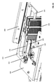
図1Aは、実施形態に従い、ステージ100上に装着中に基準縁部と対向縁部との間に位置しているスライドガラスを備える例示的な走査ステージを示す斜視図である。図示された実施形態において、走査ステージ100は、走査のためにステージ100上に位置している隣接するスライドガラス150の第1の長辺縁部に面している表面とともに位置している基準縁部110を備える。また、走査ステージ100は、走査のためにステージ100上に位置しているスライドガラス150の第2の長辺縁部に面する表面を含む、可動対向縁部120を備える。可動対向縁部120は、例えばデジタルスライド走査装置のプロセッサの制御下で、基準縁部110に向かい、または基準縁部110から離れて移動するように構成される。また、走査ステージ100は、走査ステージ100から、そしてスライドラック250中へ、スライドガラス150の脱着を容易にする、1つ以上のプルフィンガー溝部130を備える(例えば、実施形態に従い、図2Aおよび図2Bに図示される)。
FIG. 1A is a perspective view showing an exemplary scanning stage with a slide glass located between a reference edge and an opposing edge while mounted on the
これらの実施形態は、スライドガラスを基準縁部110と可動対向縁部120との間にスライドガラスの長辺縁部沿いに挟在するように、本明細書に最初に説明される。しかしながら、代替の実施形態において、スライドガラスは、基準縁部110と可動対向縁部120との間でスライドガラスの短辺縁部沿いに挟在されることができる。さらに、スライドがスライドガラスである必要はない。スライドガラス以外のスライドを、スライドガラスに関して本明細書に記載されているものと同一の方式で、ステージ100上に装着し、脱着し、そして支持することができる。
These embodiments are first described herein such that the slide glass is sandwiched between the
図示された実施形態において、図1Aでは、可動対向縁部120の表面は、スライドガラス150と接触していない。実施形態において、デジタルスライド走査装置のプロセッサは、可動対向縁部120を制御して、スライドラック250から走査ステージ100上へのスライドガラス150の装着中にスライドガラス150と接触させない。
In the illustrated embodiment, in FIG. 1A, the surface of the movable facing
図示された実施形態において、可動対向縁部120は、線形ばね142とともにロータリーベアリング140によって移動する、ばねアームを備える。しかしながら、他の市販の既製の構成要素を使用して、可動対向縁部120を移動させることができることを理解するであろう。加えて、可動対向縁部120の少なくとも一部がスライドガラス150に接触して圧力を付勢する位置と、可動対向縁部120がスライドガラス150に接触しない、またはこのスライドガラスに圧力を付勢しない位置との間で、可動対向縁部120が移動することができる限り、ばねアーム以外のいずれかの手段を使用して、可動対向縁部120を実装することができる。実施形態において、可動対向縁部120、およびこの可動対向縁部120を移動させる機構は、可動対向縁部120がスライドガラス150と接触しているときに、少なくとも2つの異なる圧力量(例えば、走査用の第1の圧力量、および脱着用の第2の圧力量)を付勢するようにプロセッサに制御させることを可能にするように実装される。
In the illustrated embodiment, the movable
図1Bは、実施形態に従い、走査中に基準縁部110と対向縁部120との間に位置しているスライドガラス150を備える走査ステージ100を示す斜視図である。図1Aと対照的に、図1Bにおいて、可動対向縁部120の表面は、スライドガラス150と接触している。上記に言及されているように、デジタルスライド走査装置のプロセッサは、可動対向縁部120を制御して、可動対向縁部120の少なくとも1つの端面を基準縁部110に向かい、スライドガラス150に接触しない位置(例えば、図1Aに示される)から、スライドガラス150に接触する位置(例えば、図1Bに示される)に移動させるように構成されることができる。可動対向縁部120は、スライドガラス150の第2の長辺縁部をスライドガラス150に面する可動対向縁部120の端面と係合させるように構成される。具体的に、可動対向縁部120の端面は、横方向の圧力をスライドガラス150に加え、スライドガラス150の第1の長辺縁部を、スライドガラス150に面している基準縁部110の表面に押し付ける。これは、走査中に、基準縁部110と可動対向縁部120の押し付けている端面との間で、スライドガラス150をステージ100の表面に固定する。
FIG. 1B is a perspective view showing a
図1Cは、実施形態に従い、ステージ100からの脱着中に基準縁部110と対向縁部120との間に位置しているスライドガラス150を備える走査ステージ100を示す斜視図である。図示されるように、可動対向縁部120の端面は、スライドガラス150と接触している。可動対向縁部120は、スライドガラス150をスライドステージ100から脱着している間に、横方向の圧力を加え、スライドガラス150の第1の長辺縁部を固定された基準縁部110の面している表面に押し付けるように構成される。固定された基準縁部110の面している表面は、スライドガラス150を挿入しているスライドラック250の側面に平行に位置し、そしてこの側面に整列することができる。
FIG. 1C is a perspective view showing a
一実施形態において、脱着中に可動対向縁部120によってスライドガラス150に加えられる圧力量は、走査中に可動対向縁部120によってスライドガラス150に加えられる圧力量より低い。例えば、デジタルスライド走査装置のプロセッサは、脱着中に可動対向縁部120がより低い圧力を端面からスライドガラス150に加えるように制御し、走査中に可動対向縁部120がより高い圧力を端面からスライドガラス150に加えるように制御することができる。
In one embodiment, the amount of pressure applied to the
図1Dは、実施形態に従い、下にある構造を図示するために取り外されているスライドガラス150および基準縁部110を備えない走査ステージ100を示す斜視図である。図示されるように、ステージ100は、スライドガラス150を下から照明する(例えば、照明系595によって)ことができるように、スライドガラス150が載る表面中に貫通孔132を備える。図示された実施形態において、そのうえ貫通孔132は、プルフィンガー溝部(複数可)130を貫通孔132の対向する側部上で2つのセクション130Aおよび130Bに分離させる。一方のセクション130A/130B中の各プルフィンガー溝部は、他方のセクション130B/130A中の対応するプルフィンガー溝部と、貫通孔を横切り一直線に整列する。
FIG. 1D is a perspective view showing a
図示されるように、貫通孔132は、スライドガラス150が載る、ステージ100のスライド支持面134によって2つ以上の側部上に囲まれる。図示された実施形態において、プルフィンガー溝部130は、スライド支持面134内で貫通孔132の両方の短辺側部上に提供される。スライド支持面134は、走査ステージ100中に凹部を形成されることができる。実施形態において、このスライド凹部の深さは、スライドガラス150がスライド支持面134上に載るときに、スライドガラス150の上面が走査ステージ100の上面と実質的に同じ高さになるようなサイズに形成されることができる。代替に、スライド凹部の深さは、スライドガラス150がスライド支持面134上に載るときに、スライドガラスの上面が走査ステージ100の上面よりわずかに下にあるようなサイズに形成されることができる。別の代替として、スライド凹部の深さは、スライドガラス150がスライド支持面134上に載るときに、スライドガラスの上面が走査ステージ100の上面よりわずかに上にあるようなサイズに形成されることができる。
As shown, the through
実施形態において、ステージ100は、基準縁部が嵌合され、固定される(例えば、1つ以上のねじを介して)基準縁部の溝部112を備える。基準縁部の溝部112は、スライドガラス150を脱着する、または挿入するスライドラック250中のスロットの側部に基準縁部110の第1の側部が平行であり、そしてこの側部と基準縁部110の第1の側部が整列するように、基準縁部110が貫通孔132の1つの側部(例えば、長辺側部)上の支持面上に位置しているように形成される。可動対向縁部120を基準縁部110よりも貫通孔132の対向する側部上のステージ100の上面に取り付ける。可動対向縁部120は、基準縁部110の第1の側面に押し付けられるスライドガラス150の長辺縁部と、スライドガラスを脱着する、または挿入するスライドラック250中のスロットの側部との間で平行な向きを維持するために、横方向の圧力をスライドガラス150に加え、スライドガラス150を基準縁部110の第1の側部に押し付けるように構成される。
In an embodiment, the
図2Aおよび図2Bは、実施形態に従い、デジタルスライド走査装置の例示的なプッシュ/プル組立体200、スライドラック250、および走査ステージ100を示す斜視図である。図示された実施形態において、プッシュ/プル組立体200は、スライドラック250中へ延伸するプッシュバー220を備えるように示される。また、図示されたプッシュ/プル組立体200は、1つ以上のプルフィンガー212を有する開口端部を含むプルバー210を備える。プルフィンガー(複数可)212は、ステージ100中の対応するプルフィンガーの溝部(複数可)130内で移動するように構成される。
2A and 2B are perspective views showing an exemplary push /
一実施形態において、デジタルスライド走査装置のプロセッサは、プッシュ/プル組立体200がスライドガラス150をスライドラック250から走査ステージ100上に装着し、スライドガラス150を走査ステージ100からスライドラック250中に脱着するように制御する。具体的に、プッシュバー220およびプルフィンガー212は、スライドラック250から出て、走査ステージ100のスライド支持面134上に、スライドガラス150を押し付けて走査するように連動する。スライドガラス150を走査した後、プッシュバー220およびプルフィンガー212は、走査ステージ100のスライド支持面134から離れて、走査ステージ100中のスライド凹部に整列し、このスライド凹部と同一の平面にあるスライドラック250中のスロット中へ、スライドガラス150を押し付けるように連動する。図2Aは、スライドガラス150を走査ステージ100上で全体的に支持するときのプッシュ/プル組立体200を示し、一方で、図2Bは、スライドガラス150を走査ステージ100上で部分的に支持し、スライドラック250のスロット内に部分的にあるとき(例えば、スライドガラス150の装着または脱着中)のプッシュ/プル組立体200を示す。
In one embodiment, the processor of the digital slide scanning device is such that the push /
図3は、実施形態に従い、基準縁部110と可動対向縁部120との間に位置している例示的なスライドガラス150を示すブロック図である。図示された実施形態において、スライドガラス150に対向する、固定された基準縁部110および可動対向縁部120の両方の対向する表面をある角度に設定する。具体的に、対面する表面の両方の底面がスライドガラス150の底面に接触しない、またはこの底面から離れて凹部を形成されるように、対面する表面の両方の上面は、スライドガラス150の上面部分に接触し、そして上面から底面に、スライドガラス150の側面から離れて徐々に後退する。換言すれば、スライドガラス150の上面において、固定された基準縁部110および可動対向縁部120の対面する表面は、スライドガラス150に接触するが、スライドガラス150の底面において、固定された基準縁部110の対面する表面とスライドガラス150との間の間隙300A、および可動対向縁部120の対向する表面とスライドガラス150との間の間隙300Bがある。傾斜している対面する表面のこの向きは、対向縁部120がスライドガラス150を基準縁部110中に横方向に押し付けるときに、下方向の圧力をスライドガラス150上に加え、スライドガラス150を走査ステージ100のスライド支持面134に固定する。
FIG. 3 is a block diagram showing an
例示的実施形態
一実施形態において、デジタルスライド走査装置は、スライドガラスが走査中に位置している表面を含むステージを備え、スライドガラスが第1の長辺縁部と第2の長辺縁部と第1の短辺縁部と第2の短辺縁部とを含む。また、走査装置は、スライドが走査のために置かれるときに、ステージに取り付けられ、スライドガラスの第1の長辺縁部に隣接して位置している基準縁部を備える。基準縁部の少なくとも一部は、スライドガラスが走査中に位置している表面より上に延在する。また、走査装置は、ステージに取り付けられ、スライドガラスの第2の長辺縁部に近位に位置している、対向縁部を含む。基準縁部と同様に、対向縁部の少なくとも一部は、スライドガラスが走査中に置かれている表面より上に延在する。また、対向縁部は、基準縁部に向かい、そして基準縁部から離れて移動するように構成される。また、走査装置は、可動対向縁部を制御するように構成されるプロセッサを含み、プロセッサは、スライドガラスの走査前に、対向縁部が基準縁部に向かい移動し、スライドガラスの第2の長辺縁部を係合してスライドガラスの第1の長辺縁部を基準縁部に押し付けるように制御する。
Exemplary Embodiments In one embodiment, the digital slide scanning device comprises a stage that includes a surface on which the slide glass is located during scanning, with the slide glass having a first long edge and a second long edge. And a first short edge and a second short edge. The scanning device also comprises a reference edge that is attached to the stage and is located adjacent to the first long edge of the slide glass when the slide is placed for scanning. At least a portion of the reference edge extends above the surface on which the glass slide is located during scanning. The scanning device also includes opposed edges that are mounted on the stage and located proximal to the second long edge of the slide glass. Similar to the reference edge, at least a portion of the opposing edge extends above the surface on which the glass slide is placed during the scan. Also, the opposing edges are configured to move towards and away from the reference edge. The scanning device also includes a processor configured to control a movable facing edge, the processor moving the facing edge towards a reference edge prior to scanning the slide glass and a second slide glass. The long side edge portion is engaged to control the first long side edge portion of the slide glass to be pressed against the reference edge portion.
一実施形態において、スライドガラスに面する基準縁部の表面は、スライドガラスに面する基準縁部の表面の下部がスライドガラスから離れて凹部を形成されるように傾斜している。同様に、実施形態において、スライドガラスに面する対向縁部の表面は、スライドガラスに面する対向縁部の表面の下部がスライドガラスから離れて凹部を形成されるように傾斜している。傾斜した対向縁部の表面がスライドガラスを傾斜した基準縁部の表面に押し付けるときに、組み合わされ傾斜した表面は、下方向に圧力を加え、スライドをステージの表面に固定する。 In one embodiment, the surface of the reference edge facing the slide glass is inclined so that the lower portion of the surface of the reference edge facing the slide glass forms a recess away from the slide glass. Similarly, in the embodiment, the surface of the facing edge portion facing the slide glass is inclined so that the lower portion of the surface of the facing edge portion facing the slide glass is separated from the slide glass to form a recess. When the surface of the sloping facing edge presses the slide glass against the surface of the sloping reference edge, the combined sloping surface applies downward pressure to secure the slide to the surface of the stage.
実施形態において、対向縁部は、スライドガラスを置くステージの表面より上で枢動する、ばねアームを備え、このばねアームは、ばねアームを作動させて対向縁部の表面をスライドガラスの第2の長辺縁部に押し付けるように構成される、線形ばねに動作可能に接続される。一実施形態において、プロセッサは、線形ばねの動作を制御することにより、対向縁部の移動を制御するように構成される。一実施形態において、プロセッサは、対向縁部を制御し、スライドラックから走査ステージ上へのスライドガラスの装着中に、基準縁部から離れて対向縁部を移動させる。実施形態において、プロセッサは、操作中対向縁部を制御して、対向縁部の表面とスライドガラスと、および基準縁部の表面とスライドガラスとの間の接触を維持する。 In an embodiment, the opposing edge comprises a spring arm that pivots above the surface of the stage on which the slide glass is placed, the spring arm activating the spring arm to bring the surface of the opposing edge to a second slide glass. Operatively connected to a linear spring configured to press against the long edge of the glass. In one embodiment, the processor is configured to control the movement of the opposing edges by controlling the operation of the linear spring. In one embodiment, the processor controls the facing edges and moves the facing edges away from the reference edge during mounting of the slide glass from the slide rack onto the scanning stage. In embodiments, the processor controls the facing edges during operation to maintain contact between the surface of the facing edges and the slide glass and between the surface of the reference edges and the slide glass.
実施形態において、方法は、スライドガラスを走査ステージの表面上に置くことを備え、スライドガラスが第1の長辺縁部、第2の長辺縁部、第1の短辺縁部、および第2の短辺縁部を含み、スライドガラスの第1の長辺縁部は、基準縁部に隣接する。また、方法は、対向縁部がスライドガラスの第2の長辺縁部を係合し、スライドガラスの第1の長辺縁部を基準縁部に押し付けるように制御することを備える。また、方法は、対向縁部とスライドガラスの第2の長辺縁部と、およびスライドガラスの第1の長辺縁部と基準縁部との間に接触を維持することを備える。一実施形態において、そのうえ方法は、対向縁部が第1の長辺縁部を基準縁部に押し付けるように制御し、プッシュ/プル組立体がステージからスライドラック中へスライドガラスを脱着するように制御することを備える。 In an embodiment, the method comprises placing a glass slide on the surface of a scanning stage, the glass slide having a first long edge, a second long edge, a first short edge, and a first. The first long edge of the slide glass, including the two short edges, is adjacent to the reference edge. The method also comprises controlling the opposing edges to engage the second long edge of the slide glass and press the first long edge of the slide glass against the reference edge. The method also comprises maintaining contact between the opposing edges and the second long edge of the slide glass, and between the first long edge of the slide glass and the reference edge. In one embodiment, the method further controls the opposed edge to press the first long edge against the reference edge so that the push / pull assembly detaches the slide glass from the stage into the slide rack. Be prepared to control.
例示的なデジタルスライド走査装置
図4Aは、本明細書で説明される様々な実施形態と関連して使用され得る、一例のプロセッサ対応デバイス550を例示するブロック図である。デバイス550の代替の形式が当業者によって理解されるように使用されてもよい。例示される実施形態では、デバイス550は、1つまたは複数のプロセッサ555、1つまたは複数のメモリ565、1つまたは複数のモーションコントローラ570、1つまたは複数のインタフェースシステム575、1つまたは複数の試料590を有する1つまたは複数のスライドガラス585を各々が支持する1つまたは複数の可動ステージ580、試料を照らす1つまたは複数の照明系595、光学軸に沿って進む光路605を各々が規定する1つまたは複数の対物レンズ600、1つまたは複数の対物レンズポジショナ630、1つまたは複数の任意選択の落射照明系635(例えば、蛍光発光スキャナシステムに含まれる)、1つまたは複数の焦点調節光学系610、1つまたは複数のライン走査カメラ615、および/または1つまたは複数の追加のカメラ620(例えばライン走査カメラまたはエリア走査カメラ)を備え、その各々が試料590および/またはスライドガラス585上で別個の視野625を規定するデジタル撮像デバイス(本明細書では、スキャナシステム、走査システム、走査装置、デジタル走査装置、デジタルスライド走査装置などとも称される)として提示される。スキャナシステム550の様々な要素は、1つまたは複数の通信バス560を介して通信可能に結合される。簡略化のために、スキャナシステム550の様々な要素の各々のうちの1つまたは複数が存在する場合があるが、それらの要素は、適切な情報を搬送するために複数で説明する必要があるときを除いて、単数で説明される。
Illustrative Digital Slide Scanning Device FIG. 4A is a block diagram illustrating an example processor-enabled
1つまたは複数のプロセッサ555は、例えば命令を並列に処理することが可能な中央処理装置(「CPU」)および別個のグラフィックプロセシングユニット(「GPU」)を含んでもよく、あるいは1つまたは複数のプロセッサ555は、命令を並列に処理することが可能なマルチコアプロセッサを含んでもよい。追加の別個のプロセッサが、特定の構成要素を制御するため、または画像処理などの特定の機能を実行するために設けられてもよい。例えば、追加のプロセッサは、データ入力を管理する補助プロセッサ、浮動小数点数学演算を実行する補助プロセッサ、信号処理アルゴリズムの高速実行に適切なアーキテクチャを有する特殊目的プロセッサ(例えば、デジタルシグナルプロセッサ)、メインプロセッサに従属するスレーブプロセッサ(例えば、バックエンドプロセッサ)、ライン走査カメラ615、ステージ580、対物レンズ225および/またはディスプレイ(図示せず)を制御するための追加のプロセッサを含んでもよい。そのような追加のプロセッサは、別個の離散プロセッサであってもよく、またはプロセッサ555と統合されてもよい。
One or
メモリ565は、プロセッサ555によって実行することができるプログラムに関するデータおよび命令の記憶を実現する。メモリ565は、データおよび命令を記憶する1つまたは複数の揮発性および/または不揮発性コンピュータ可読記憶媒体を含んでよく、例えばランダムアクセスメモリ、読み出し専用メモリ、ハードディスクドライブ、着脱可能記憶ドライブなどを含んでもよい。プロセッサ555は、メモリ565に記憶された命令を実行し、スキャナシステム550の全体的な機能を実行するために、通信バス560を介してスキャナシステム550の様々な要素と通信するように構成される。
1つまたは複数の通信バス560は、アナログ電気信号を搬送するように構成された通信バス560を含んでもよく、またデジタルデータを搬送するように構成された通信バス560を含んでもよい。したがって、1つまたは複数の通信バス560を介したプロセッサ555、モーションコントローラ570および/またはインタフェースシステム575からの通信は、電気信号およびデジタルデータの両方を含んでもよい。プロセッサ555、モーションコントローラ570および/またはインタフェースシステム575はまた、無線通信リンクを介して、走査システム550の様々な要素のうちの1つまたは複数と通信するように構成されてもよい。
The one or more communication buses 560 may include a communication bus 560 configured to carry analog electrical signals, or may include a communication bus 560 configured to carry digital data. Thus, communication from the
動き制御システム570は、ステージ580のX、Yおよび/またはZ移動(X-Y面内)および/または対物レンズ600のX、Yおよび/またはZ移動(例えば、対物レンズポジショナ630を介してX-Y面に対して直交してZ軸に沿った)を正確に制御し調整するように構成される。動き制御システム570はまた、スキャナシステム550におけるいずれかの他の移動部分の移動を制御するようにも構成される。例えば、蛍光発光スキャナの実施形態では、動き制御システム570は、落射照明系635において光学フィルタなどの移動を調整するように構成される。
The
インタフェースシステム575は、スキャナシステム550が他のシステムおよび人的操作と連動することを可能にする。例えば、インタフェースシステム575は、オペレータに情報を直接提供し、および/またはオペレータからの直接入力を可能にするユーザインタフェースを含んでもよい。インタフェースシステム575はまた、走査システム550と、直接接続された1つ以上の外部デバイス(例えば、プリンタ、着脱可能記憶媒体)またはネットワーク(図示せず)を介してスキャナシステム550に接続された画像サーバシステム、オペレータステーション、ユーザステーション、および管理サーバシステムなどの外部デバイスとの間の通信およびデータ転送を促進するように構成される。
The
照明系595は、試料590の一部を照射するように構成される。照明系は、例えば、光源および照明光学系を含んでもよい。光源は、光出力を最大化する凹型反射ミラーと、熱を抑制するKG-1フィルタを有する可変輝度ハロゲン光源を備えてよい。光源はまた、いずれかのタイプのアークランプ、レーザまたは他の光源を備える場合もある。一実施形態では、照明系595は、透過モードにおいて試料590を照射し、その結果、ライン走査カメラ615および/または領域走査カメラ620は、試料590を通じて伝送された光エネルギーを検知する。代替として、または組み合わせて、照明系595はまた、反射モードにおいて試料590を照射するように構成されてもよく、その結果、ライン走査カメラ615および/またはカメラ620は、試料590から反射された光エネルギーを検知する。照明系595は、光学顕微鏡検査の任意の既知のモードにおける顕微鏡の試料590の検査に適するように構成されてもよい。 The illumination system 595 is configured to illuminate a portion of the sample 590. The illumination system may include, for example, a light source and an illumination optical system. The light source may include a concave reflection mirror that maximizes the light output and a variable luminance halogen light source having a KG-1 filter that suppresses heat. The light source may also include any type of arc lamp, laser or other light source. In one embodiment, the illumination system 595 illuminates the sample 590 in transmission mode so that the line scanning camera 615 and / or the region scanning camera 620 detects the light energy transmitted through the sample 590. Alternatively or in combination, the illumination system 595 may also be configured to illuminate the sample 590 in reflection mode, so that the line scanning camera 615 and / or the camera 620 is the light reflected from the sample 590. Detect energy. The illumination system 595 may be configured to be suitable for inspection of a sample 590 of a microscope in any known mode of optical microscopy.
一実施形態では、スキャナシステム550は任意選択で、蛍光発光走査のためにスキャナシステム550を最適化する落射照明系635を含む。蛍光発光走査は、蛍光発光分子を含む試料590の走査であり、蛍光発光分子は、特定の波長(励起)で光を吸収することができる感光性分子である。このような感光性分子はまた、より高い波長(放射)においても光を放射する。このようなフォトルミネセンス現象の効率性が非常に低いことが理由で、放射される光の量が非常に少ない場合が多い。この少ない量の放射される光は典型的には、試料590を走査およびデジタル化するための従来の技術(例えば、透過モード顕微鏡検査)を妨げる。有利なことに、スキャナシステム550の任意選択の蛍光発光スキャナシステムの実施形態では、複数の線形センサ配列を含むライン走査カメラ615(例えば、時間遅延統合(「TDI」)ライン走査カメラ)の使用は、ライン走査カメラ615の複数の線形センサ配列の各々に試料590の同一の領域を暴露することによって、ライン走査カメラの光への感度を増大させる。これは特に、放射された少ない光によりわずかな蛍光発光試料を走査するときに有益である。
In one embodiment, the
したがって、蛍光発光スキャナシステムの実施形態では、ライン走査カメラ615は好ましくは、モノクロTDIライン走査カメラである。有利なことに、モノクロ画像は、それらが試料に存在する様々なチャネルからの実信号のさらなる正確な表現を提供することを理由に、蛍光発光顕微鏡検査において理想である。当業者によって理解されるように、蛍光発光試料590は、異なる波長で光を放射する複数の蛍光染料によりラベル付けされることができ、異なる波長は、「チャネル」とも称される。 Therefore, in the embodiment of the fluorescence light emitting scanner system, the line scanning camera 615 is preferably a monochrome TDI line scanning camera. Advantageously, monochrome images are ideal for fluorescence microscopy because they provide a more accurate representation of real signals from the various channels present in the sample. As will be appreciated by those of skill in the art, fluorescent light emitting samples 590 can be labeled with multiple fluorescent dyes that emit light at different wavelengths, the different wavelengths being also referred to as "channels".
さらに、最低の信号レベルおよび最高の信号レベルの様々な蛍光発光試料が、検知するライン走査カメラ615についての広いスペクトルの波長を提示することを理由に、ライン走査カメラ615が検知することができる低い信号レベルおよび高い信号レベルが同様に広いことが望ましい。したがって、蛍光発光スキャナの実施形態では、蛍光発光走査システム550において使用されるライン走査カメラ615は、モノクロの10ビットの64個の線形配列TDIライン走査カメラである。ライン走査カメラ615についての様々なビット深度が走査システム550の蛍光発光スキャナの実施形態による使用のために採用されることができることに留意されるべきである。
In addition, the low signal level that the line scanning camera 615 can detect because the various fluorescent samples with the lowest and highest signal levels present a wide spectral wavelength for the line scanning camera 615 to detect. It is desirable that the signal level and the high signal level are similarly wide. Therefore, in the embodiment of the fluorescence light emitting scanner, the line scanning camera 615 used in the fluorescence light emitting
可動ステージ580は、プロセッサ555またはモーションコントローラ570の制御の下での正確なX-Yの移動のために構成される。可動ステージはまた、プロセッサ555またはモーションコントローラ570の制御の下でのZ移動のために構成されてもよい。可動ステージは、ライン走査カメラ615および/または領域走査カメラによる画像データの捕捉の間、所望の位置に試料を位置付けるように構成される。可動ステージはまた、走査方向において実質的に一定の速度に試料590を加速させ、次いで、ライン走査カメラ615による画像データの捕捉の間、実質的に一定の速度を維持するように構成される。一実施形態では、スキャナシステム550は、可動ステージ580上での試料590の位置において支援するために高精度かつ厳格に調整されたX-Y格子を採用してもよい。一実施形態では、可動ステージ580は、X軸およびY軸の両方において採用された高精度エンコーダを有するリニアモータに基づくX-Yステージである。例えば、非常に正確なナノメータエンコーダを、走査方向における軸上で、および走査方向に垂直な方向における軸上で、および走査方向と同一の面上で使用することができる。ステージはまた、試料590がその上に配置されたスライドグラス585を支持するように構成される。
試料590は、光学顕微鏡検査によって検査されてもよい、任意のものであることができる。例えば、顕微鏡スライドグラス585は、組織および細胞、染色体、DNA、タンパク質、血液、骨髄、尿、バクテリア、気泡、生検材料、または死亡しもしくは生存しているかのいずれかであり、着色されもしくは着色されていないかのいずれかであり、ラベル付けされているもしくはラベル付けされていないかのいずれかである、任意の他のタイプの生物材料を含む標本についての観察用の基板として頻繁に使用される。試料590はまた、マイクロアレイとして一般的に知られている任意の試料および全ての試料を含む、任意のタイプのスライドもしくは他の基板上に堆積された任意のタイプのDNA、またはcDNAもしくはRNAなどのDNA関連材料、またはタンパク質の配列であってもよい。試料590は、微量定量プレート(例えば、96ウェルプレート)であってもよい。試料590の他の例には、集積回路基板、電気泳動レコード、ペトリ皿、フィルム、半導体材料、法医学材料または機械加工部品が含まれる。
Sample 590 can be any that may be inspected by light microscopy. For example, a
対物レンズ600は、対物レンズポジショナ630上に取り付けられ、対物レンズポジショナ630は、一実施形態では、対物レンズ600によって規定された光学軸に沿って対物レンズ600を移動させるために非常に正確なリニアモータを採用する。例えば、対物レンズポジショナ630のリニアモータは、50ナノメートルのエンコーダを含んでもよい。X、Yおよび/またはZ軸におけるステージ580および対物レンズ600の相対的な位置は、走査システム550全体の動作のためにコンピュータ実行可能プログラムされたステップを含む、情報および命令を記憶するためのメモリ565を採用するプロセッサ555の制御の下、モーションコントローラ570を使用して閉ループ方式において調整され制御される。
The objective lens 600 is mounted on the objective lens positioner 630, and the objective lens positioner 630, in one embodiment, is a very accurate linear for moving the objective lens 600 along the optical axis defined by the objective lens 600. Adopt a motor. For example, the linear motor of the objective lens positioner 630 may include an encoder of 50 nanometers. The relative positions of the
一実施形態では、対物レンズ600は、望ましい最高空間分解能に対応する開口数を有する平面アポクロマート(「APO」)無限補正対物レンズであり、対物レンズ600は、透過モード照明顕微鏡検査、反射モード照明顕微鏡検査および/または落射照明モード蛍光発光顕微鏡検査(例えば、Olympus 40X、0.75NAもしくは20X、0.75NA)に適切である。有利なことに、対物レンズ600は、色収差および球面収差を補正することが可能である。対物レンズ600が無限に補正されることを理由に、焦点調節光学系610は、対物レンズ600の上で光学経路605内に配置されることができ、対物レンズ600を通過する光ビームは平行光ビームとなる。焦点調節光学系610は、ライン走査カメラ615および/またはエリア走査カメラ620の光反応素子上に対物レンズ600によって捕捉された光信号の焦点を調節し、フィルタ、倍率変換器レンズおよび/または同様のものなどの光学構成要素を含んでもよい。焦点調節光学系610と組み合わされた対物レンズ600は、走査システム550に関する全倍率を提供する。一実施形態では、焦点調節光学系610は、チューブレンズおよび任意選択の2Xの倍率変換器を包含してもよい。有利なことに、2Xの倍率変換器によって、本来の20Xの対物レンズ600が40Xの倍率で試料590を走査することが可能になる。
In one embodiment, the objective lens 600 is a planar apochromat (“APO”) infinitely corrected objective lens with a numerical aperture corresponding to the desired maximum spatial resolution, and the objective lens 600 is a transmission mode illumination microscopy, a reflection mode illumination microscope. Suitable for inspection and / or epi-illumination mode fluorescence emission microscopy (eg, Olympus 40X, 0.75NA or 20X, 0.75NA). Advantageously, the objective lens 600 is capable of correcting chromatic aberration and spherical aberration. The
ライン走査カメラ615は、画像素子(「画素」)の少なくとも1つの線形配列を含む。ライン走査カメラは、モノクロまたはカラーであってもよい。カラーライン走査カメラは典型的には、少なくとも3つの線形配列を有し、モノクロライン走査カメラは、単一の線形配列または複数の線形配列を有してもよい。カメラの一部としてパッケージ化されるか、撮像電子モジュールにカスタム統合されているかに関わらず、任意のタイプの単数または複数のリニアアレイを使用することができる。例えば、3つのリニアアレイ(「赤-緑-青」、すなわち「RGB」)カラーライン走査カメラまたは96個のリニアアレイモノクロTDIが使用されてもよい。TDIライン走査カメラは典型的には、標本のこれより前に撮像された領域からの光度データを合計することによって、出力信号において大幅に良好な信号対雑音比(「SNR」)を提供し、統合ステージの数の平方根に比例するSNRにおける増大をもたらす。TDIライン走査カメラは、複数のリニアアレイを含む。例えば、24個、32個、48個、64個、96個、またはそれよりも多いリニアアレイを有するTDIライン走査カメラが利用可能である。スキャナシステム550はまた、512個の画素を有するもの、1024個の画素を有するもの、および4096個の画素と同数の画素を有するその他を含む、様々なフォーマットにおいて製造された線形配列を支持する。同様に、様々なピクセルサイズを有するリニアアレイをスキャナシステム550において使用することもできる。いずれかのタイプのライン走査カメラ615の選択のための突出した要件は、ステージ580の動きがライン走査カメラ615のライン速度と同期されることができ、その結果、試料590のデジタル画像の捕捉の間、ステージ580がライン走査カメラ615に対して動くことができることである。
The line scanning camera 615 includes at least one linear array of image elements (“pixels”). The line scanning camera may be monochrome or color. A color line scanning camera typically has at least three linear arrays, and a monochrome line scanning camera may have a single linear array or a plurality of linear arrays. Any type of singular or multiple linear arrays can be used, whether packaged as part of the camera or custom integrated into the imaging electronics module. For example, three linear arrays (“red-green-blue” or “RGB”) color line scanning cameras or 96 linear array monochrome TDIs may be used. A TDI line scanning camera typically provides a significantly better signal-to-noise ratio (“SNR”) in the output signal by summing the light intensity data from areas previously imaged in the sample. It results in an increase in SNR proportional to the square root of the number of integration stages. The TDI line scanning camera includes a plurality of linear arrays. For example, TDI line scanning cameras with 24, 32, 48, 64, 96, or more linear arrays are available. The
ライン走査カメラ615によって生成された画像データは、メモリ565の一部に記憶され、試料590の少なくとも一部の連続するデジタル画像を生成するようにプロセッサ555によって処理される。連続するデジタル画像はさらに、プロセッサ555によって処理されることができ、改正された連続するデジタル画像もメモリ565に記憶されることができる。
The image data generated by the line scanning camera 615 is stored in a portion of
2つ以上のライン走査カメラ615を有する実施形態では、ライン走査カメラ615のうちの少なくとも1つは、撮像センサとして機能するように構成された他のライン走査カメラ615のうちの少なくとも1つとの組み合わせで動作する焦点調節センサとして機能するように構成されることができる。焦点調節センサは、撮像センサと同一の光軸上に論理的に位置付けられることができ、または焦点調節センサは、スキャナシステム550の走査方向に対して撮像センサの前もしくは後に論理的に位置付けられてもよい。焦点調節センサとして機能する少なくとも1つのライン走査カメラ615を有するそのような実施形態では、焦点調節センサによって生成された画像データは、メモリ565の一部に記憶され、スキャナシステム550が試料590と対物レンズ600との間の相対的な距離を調節して、走査の間の試料上の焦点を維持することを可能にするために焦点調節情報を生成するように1つ以上のプロセッサ555によって処理される。加えて、一実施形態において、焦点調節センサとして機能する、少なくとも1つのライン走査カメラ615は、焦点調節センサの複数の個々の画素のそれぞれが異なる論理的な高さで光路605沿いに位置しているように指向されることができる。
In an embodiment having two or more line scanning cameras 615, at least one of the line scanning cameras 615 is combined with at least one of the other line scanning cameras 615 configured to function as an imaging sensor. It can be configured to function as a focus adjustment sensor that operates on. The focus adjustment sensor can be logically positioned on the same optical axis as the image sensor, or the focus adjustment sensor is logically positioned before or after the image sensor with respect to the scanning direction of the
動作中、スキャナシステム550の様々な構成要素およびメモリ565に記憶されたプログラムされたモジュールは、スライドガラス585上に配置された試料590の自動走査およびデジタル化を可能にする。スライドグラス585は、試料590を走査するためのスキャナシステム550の可動ステージ580上に固定して配置される。プロセッサ555の制御の下、可動ステージ580は、ライン走査カメラ615による検知のために実質的に一定の速度に試料590を加速させ、ステージの速度は、ライン走査カメラ615のライン速度と同期される。画像データのストライプを走査した後、可動ステージ580は、試料590を減速させ、実質的に完全に停止させる。可動ステージ580は次いで、画像データの後続のストライプ(例えば、隣接するストライプ)の走査のために試料590を位置付けるために走査方向に直交して移動する。試料590の全ての部分または試料590全体が走査されるまで追加のストライプが続いて走査される。
During operation, various components of the
例えば、試料590のデジタル走査の間、試料590の連続したデジタル画像は、画像ストライプを形成するために一緒に組み合わされた複数の連続した視野として取得される。複数の隣接する画像ストライプも同様に、試料590の一部分またはその全体の連続したデジタル画像を形成するために一緒に組み合わされる。試料590の走査は、垂直画像ストライプまたは水平画像ストライプを取得することを含んでもよい。試料590の走査は、上から下、下から上、またはその両方(双方向)のいずれかであってよく、試料上のいずれの地点において開始してもよい。代替として、試料590の走査は、左から右、右から左、またはその両方(双方向)のいずれであってもよく、試料上のいずれの地点において開始してもよい。加えて、画像ストライプは、隣接するやり方で、または連続するやり方で取得される必要はない。さらに、結果として生じる試料590の画像は、試料590の全体の画像または試料590の一部分のみの画像であってもよい。 For example, during a digital scan of sample 590, a continuous digital image of sample 590 is acquired as a plurality of continuous fields of view combined together to form an image stripe. Multiple adjacent image stripes are likewise combined together to form a continuous digital image of a portion of sample 590 or its entire portion. Scanning of sample 590 may include acquiring vertical or horizontal image stripes. Scanning of the sample 590 may be from top to bottom, bottom to top, or both (bidirectional) and may start at any point on the sample. Alternatively, scanning the sample 590 may be left-to-right, right-to-left, or both (bidirectional) and may begin at any point on the sample. In addition, image stripes need not be acquired in an adjacent or contiguous manner. Further, the resulting image of the sample 590 may be an entire image of the sample 590 or an image of only a portion of the sample 590.
一実施形態では、コンピュータ実行可能命令(例えば、プログラムされたモジュールおよびソフトウェア)がメモリ565に記憶され、実行される際、走査システム550が本明細書で説明される様々な機能を実行することを可能にする。この説明では、用語「コンピュータ可読記憶媒体」は、プロセッサ555による実行のためにコンピュータ実行可能命令を記憶し、これを走査システム550に提供するのに使用される任意の媒体を指すのに使用される。このような媒体の例には、メモリ565、および直接的、または例えばネットワーク(図示せず)を介して間接的のいずれかで走査システム550と通信可能に結合された任意の着脱可能なまたは外部の記憶媒体(図示せず)が含まれる。
In one embodiment, when computer executable instructions (eg, programmed modules and software) are stored and executed in
図4Bは、電荷結合素子(CCD)アレイとして実装され得る、単一のリニアアレイ640を有するライン走査カメラを例示する。単一のリニアアレイ640は、複数の個々のピクセル645を含む。例示される実施形態では、単一の線形配列640は、4096個の画素を有する。代替的な実施形態では、線形配列640は、さらに多くのまたはさらに少ない画素を有してもよい。例えば、線形配列の共通フォーマットは、512個、1024個、および4096個の画素を含む。ピクセル645は、リニアアレイ640についての視野625を規定するために線形方式で配列される。視野625のサイズは、スキャナシステム550の倍率に従って変化する。
FIG. 4B illustrates a line scanning camera with a single
図4Cは、各々がCCDアレイとして実装され得る、3つのリニアアレイを有するライン走査カメラを例示する。3つのリニアアレイは合体してカラーアレイ650を形成する。一実施形態では、カラーアレイ650内の各々の個々のリニアアレイは、異なる色の強さ、例えば、赤、緑または青を検出する。カラーアレイ650内の各々の個々のリニアアレイからのカラー画像データが組み合わされて、カラー画像データの単一の視野625を形成する。
FIG. 4C illustrates a line scanning camera with three linear arrays, each of which can be mounted as a CCD array. The three linear arrays combine to form the
図4Dは、各々がCCDアレイとして実装され得る、複数のリニアアレイを有するライン走査カメラを例示する。複数のリニアアレイは、合体してTDIアレイ655を形成する。有利なことに、TDIライン走査カメラは、標本のこれより前に撮像された領域からの光度データを合計することによって、その出力信号において大幅に良好なSNRを提供し、リニアアレイの数(統合ステージとも称される)の平方根に比例するSNRにおける増大をもたらす。TDIライン走査カメラは、より多様な数のリニアアレイを含んでもよい。例えば、TDIライン走査カメラの一般的な形態は、24個、32個、48個、64個、96個、120個またはそれより多いリニアアレイを含む。
FIG. 4D illustrates a line scanning camera with a plurality of linear arrays, each of which can be mounted as a CCD array. The plurality of linear arrays are combined to form the
開示される実施形態の上記の説明は、いずれかの当業者が本発明を作成する、または使用することを可能にするために提供される。それらの実施形態に対する様々な修正は、当業者にとって容易に明らかであり、本明細書で説明された一般的な原理は、本発明の精神または範囲から逸脱することなく他の実施形態に適用されることができる。よって、本明細書で提示される説明および図面は、本発明の現時点で好ましい実施形態を表し、したがって、本発明によって広く考慮される主題を表すことが理解されることになる。本発明の範囲は、当業者にとって明白になり得る他の実施形態を完全に包含すること、ならびに本発明の範囲はこれにより限定されないことをさらに理解されたい。 The above description of the disclosed embodiments is provided to allow any person skilled in the art to create or use the invention. Various modifications to those embodiments will be readily apparent to those of skill in the art, and the general principles described herein apply to other embodiments without departing from the spirit or scope of the invention. Can be Accordingly, it will be understood that the description and drawings presented herein represent the present preferred embodiments of the invention and thus represent the subject matter broadly considered by the invention. It should be further understood that the scope of the invention fully embraces other embodiments that may be apparent to those skilled in the art, and that the scope of the invention is not thereby limited.
Claims (14)
走査中にスライド(150)を支持するように構成される支持面(134)を含むステージ(100)と、
前記ステージに取り付けられる基準縁部(110)と、
前記ステージに取り付けられる可動対向縁部(120)と、
少なくとも1つのプロセッサと、
を備え、
前記スライドは、第1の側面および前記第1の側面に対向する第2の側面を含み、
前記基準縁部の対面側面は、スライドが前記支持面上にあるときに、前記基準縁部の前記対面側面が前記スライドの前記第1の側面に面するように、前記支持面より上に延在し、
前記可動対向縁部の対面側面は、スライドが前記支持面上にあるときに、前記可動対向縁部の前記対面側面が前記スライドの前記第2の側面に対向するように、前記支持面より上に延在し、前記可動対向縁部(120)は前記基準縁部(110)に向かい、および、前記基準縁部(110)から離れて移動するように構成され、
前記少なくとも1つのプロセッサは、
スライド(150)が、スライドを保持するように構成される複数のスロットを含むスライドラック中のスロットから前記ステージ(100)の前記支持面上に装着されているときに、いかなる圧力も前記可動対向縁部(120)から前記スライドの前記第2の側面に加えないために、前記可動対向縁部(120)が前記スライドの前記第2の側面から離れて残るように制御し、
前記スライド(150)が走査されているときに、前記可動対向縁部(120)から前記スライドの前記第2の側面に第1の圧力量を加えるために、前記可動対向縁部が前記スライドの前記第2の側面に接触するように制御し、
前記スライドが前記ステージ(100)の前記支持面から前記スライドラック中のスロット中に脱着されているときに、前記可動対向縁部(120)から前記スライドの前記第2の側面に、前記第1の圧力量未満である第2の圧力量を加えるために、前記可動対向縁部(120)が前記スライドの前記第2の側面に接触するように制御する、
ように構成される、
デジタルスライド走査装置(550)。 The digital slide scanning device (550) is a digital slide scanning device (550) .
A stage (100) including a support surface (134) configured to support the slide (150) during scanning.
A reference edge (110) attached to the stage and
Movable facing edges (120) attached to the stage and
With at least one processor
Equipped with
The slide includes a first side surface and a second side surface facing the first side surface.
The facing side surface of the reference edge extends above the support surface so that the facing side surface of the reference edge faces the first side surface of the slide when the slide is on the support surface. Being there
The facing side surface of the movable facing edge portion is above the supporting surface so that the facing side surface of the movable facing edge portion faces the second side surface of the slide when the slide is on the support surface. The movable facing edge (120) is configured to move towards and away from the reference edge ( 110) .
The at least one processor
When the slide (150) is mounted on the support surface of the stage (100) from a slot in a slide rack that includes a plurality of slots configured to hold the slide, any pressure is movable and opposed. Controlled so that the movable opposed edge ( 120) remains away from the second side of the slide so that the edge (120) does not add to the second side of the slide.
When the slide (150) is being scanned, the movable facing edge portion of the slide is subjected to a first pressure amount from the movable facing edge portion (120) to the second side surface of the slide. Controlled to come into contact with the second side surface,
When the slide is detached from the support surface of the stage (100) into a slot in the slide rack, the first side surface of the slide from the movable facing edge portion (120) to the second side surface of the slide. In order to apply a second pressure amount less than the pressure amount of , the movable facing edge portion (120) is controlled to be in contact with the second side surface of the slide.
Is configured as
Digital slide scanning device (550) .
前記基準縁部の前記対面側面の前記上部は、前記スライドに接触し、前記基準縁部の前記対面側面の前記上部は、前記スライド上で前記支持面に向かい圧力を加える、
請求項1に記載のデジタルスライド走査装置。 When the slide is on the support surface, the upper part of the facing side surface of the reference edge portion (110) contacts the slide, and the lower part of the facing side surface of the reference edge portion separates from the slide to form a recess. As such, the facing side surface of the reference edge is inclined with respect to the support surface (134) .
The upper part of the facing side surface of the reference edge is in contact with the slide, and the upper part of the facing side surface of the reference edge applies pressure on the slide toward the support surface.
The digital slide scanning apparatus according to claim 1.
前記可動対向縁部の前記対面側面の前記上部が前記スライドに接触するときに、前記可動対向縁部の前記対面側面の前記上部は、前記スライド上で前記支持面に向かい圧力を加える、
請求項1に記載のデジタルスライド走査装置。 When the slide is on the support surface, the upper part of the facing side surface of the reference edge is in contact with the slide, and the lower part of the facing side surface of the movable facing edge portion is separated from the slide to form a recess. As described above, the facing side surface of the movable facing edge portion (120) is inclined with respect to the supporting surface.
When the upper portion of the facing side surface of the movable facing edge portion comes into contact with the slide, the upper portion of the facing side surface of the movable facing edge portion applies pressure toward the support surface on the slide.
The digital slide scanning apparatus according to claim 1.
請求項1に記載のデジタルスライド走査装置。 The movable facing edge comprises an arm that pivots toward or away from the reference edge.
The digital slide scanning apparatus according to claim 1.
請求項4に記載のデジタルスライド走査装置。 The arm is a spring arm, and the stage further comprises a spring (142) configured to actuate the spring arm and pivot towards or away from the reference edge. Prepare, prepare
The digital slide scanning apparatus according to claim 4 .
請求項5に記載のデジタルスライド走査装置。 The spring is a linear spring (142) .
The digital slide scanning apparatus according to claim 5 .
請求項4から6のいずれか1項に記載のデジタルスライド走査装置。 The digital slide scanning device further comprises a rotary bearing (140) attached to the arm, the at least one processor being configured to pivot the arm via the rotary bearing.
The digital slide scanning apparatus according to any one of claims 4 to 6 .
請求項1から6のいずれかに記載のデジタルスライド走査装置。 When the slide is mounted onto the support surface from a slot in the slide rack, the at least one processor controls the movable facing edge to move away from the reference edge.
The digital slide scanning apparatus according to any one of claims 1 to 6 .
スライドを保持するように構成される複数のスロットを含むスライドラックと、
前記スライドラック中の前記複数のスロットのそれぞれから前記支持面上にスライドを装着し、前記支持面から前記スライドラック中の前記複数のスロットのそれぞれの中に脱着するように構成される組立体と、
をさらに備え、
前記少なくとも1つのプロセッサは、前記組立体を制御して、前記スライドラック中の前記複数のスロットのそれぞれから前記支持面上にスライドを装着させ、前記支持面から前記スライドラック中の前記複数のスロットのそれぞれの中にスライドを脱着させるように構成される、
請求項1に記載のデジタルスライド走査装置。 The digital slide scanning device is
A slide rack with multiple slots configured to hold slides,
With an assembly configured to mount slides on the support surface from each of the plurality of slots in the slide rack and detach from the support surface into each of the plurality of slots in the slide rack. ,
Further prepare
The at least one processor controls the assembly to mount slides on the support surface from each of the plurality of slots in the slide rack, and the plurality of slots in the slide rack from the support surface. It is configured to attach and detach the slide in each of the
The digital slide scanning apparatus according to claim 1.
請求項9に記載のデジタルスライド走査装置。 The reference edge is parallel to the sides of the plurality of slots and aligns with the sides.
The digital slide scanning apparatus according to claim 9 .
請求項1に記載のデジタルスライド走査装置。 The support surface comprises a through hole through which the slide glass can be illuminated while on the support surface.
The digital slide scanning apparatus according to claim 1.
請求項11に記載のデジタルスライド走査装置。 The digital slide scanning device further comprises an illumination system configured to illuminate the slide glass on the support surface from below the support surface through the through hole while the slide glass is being scanned. ,
The digital slide scanning apparatus according to claim 11 .
請求項1に記載のデジタルスライド走査装置。 Each slide is a rectangle with opposed long side sides and opposed short side sides, the first side surface and the second side surface being on the opposite long side side of each slide.
The digital slide scanning apparatus according to claim 1.
前記デジタルスライド走査装置(550)は、
走査中にスライド(150)を支持するように構成される支持面(134)を含む前記ステージと、
前記ステージに取り付けられる基準縁部(110)と、
前記ステージに取り付けられる可動対向縁部(120)と、
少なくとも1つのプロセッサと、
を備え、
前記スライドは、第1の側面および前記第1の側面に対向する第2の側面を含み、
前記基準縁部の対面側面は、スライドが前記支持面上にあるときに、前記基準縁部の前記対面側面が前記スライドの前記第1の側面に対向するように、前記支持面より上に延在し、
前記可動対向縁部の対面側面は、スライドが前記支持面上にあるときに、前記可動対向縁部(120)の前記対面側面が前記スライドの前記第2の側面に対向するように、前記支持面より上に延在し、
前記方法は、前記少なくとも1つのプロセッサによって、
スライド(150)が、スライドを保持するように構成される複数のスロットを含むスライドラック中のスロットから前記ステージ(100)の前記支持面(134)上に装着されているときに、いかなる圧力も前記可動対向縁部から前記スライドの前記第2の側面に加えないために、前記可動対向縁部(120)が前記スライドの前記第2の側面から離れて残るように制御することと、
前記スライドが走査されているときに、前記可動対向縁部から前記スライドの前記第2の側面に第1の圧力量を加えるために、前記可動対向縁部(120)が前記スライドの前記第2の側面に接触するように制御することと、
前記スライドが前記ステージの前記支持面(134)から前記スライドラック中のスロット中に脱着されているときに、前記可動対向縁部(120)から前記スライドの前記第2の側面に、前記第1の圧力量未満である第2の圧力量を加えるために、前記可動対向縁部(120)が前記スライドの前記第2の側面に接触するように制御することと、
を含む方法。 A method of controlling a stage (100) in a digital slide scanning device.
The digital slide scanning device (550) is
The stage comprising a support surface (134) configured to support the slide (150) during scanning.
A reference edge (110) attached to the stage and
Movable facing edges (120) attached to the stage and
With at least one processor
Equipped with
The slide includes a first side surface and a second side surface facing the first side surface.
The facing side surface of the reference edge extends above the support surface so that the facing side surface of the reference edge faces the first side surface of the slide when the slide is on the support surface. Being there
The facing side surface of the movable facing edge portion is supported so that the facing side surface of the movable facing edge portion (120) faces the second side surface of the slide when the slide is on the support surface. Extends above the surface,
The method is performed by the at least one processor.
Any pressure when the slide (150) is mounted on the support surface (134) of the stage (100) from a slot in a slide rack that includes a plurality of slots configured to hold the slide. In order to prevent the movable facing edge portion from adding to the second side surface of the slide, the movable facing edge portion (120) is controlled to remain away from the second side surface of the slide.
When the slide is being scanned, the movable facing edge portion (120) is the second side of the slide in order to apply a first pressure amount from the movable facing edge portion to the second side surface of the slide. To control it so that it touches the side of the
When the slide is detached from the support surface (134) of the stage into a slot in the slide rack, the movable facing edge (120) is attached to the second side surface of the slide. In order to apply a second pressure amount that is less than the pressure amount of , the movable facing edge portion (120) is controlled to be in contact with the second side surface of the slide.
How to include.
Applications Claiming Priority (3)
| Application Number | Priority Date | Filing Date | Title |
|---|---|---|---|
| US201762568203P | 2017-10-04 | 2017-10-04 | |
| US62/568,203 | 2017-10-04 | ||
| PCT/US2018/054460 WO2019071040A1 (en) | 2017-10-04 | 2018-10-04 | Opposing edges system for scanning and processing glass slides |
Publications (3)
| Publication Number | Publication Date |
|---|---|
| JP2020537173A JP2020537173A (en) | 2020-12-17 |
| JP2020537173A5 JP2020537173A5 (en) | 2021-11-11 |
| JP7004808B2 true JP7004808B2 (en) | 2022-01-21 |
Family
ID=65897156
Family Applications (1)
| Application Number | Title | Priority Date | Filing Date |
|---|---|---|---|
| JP2020518679A Active JP7004808B2 (en) | 2017-10-04 | 2018-10-04 | Opposed edge system for scanning and processing glass slides |
Country Status (5)
| Country | Link |
|---|---|
| US (1) | US11561232B2 (en) |
| EP (1) | EP3625608A4 (en) |
| JP (1) | JP7004808B2 (en) |
| CN (1) | CN111183387B (en) |
| WO (1) | WO2019071040A1 (en) |
Families Citing this family (5)
| Publication number | Priority date | Publication date | Assignee | Title |
|---|---|---|---|---|
| WO2019071040A1 (en) | 2017-10-04 | 2019-04-11 | Leica Biosystems Imaging, Inc. | Opposing edges system for scanning and processing glass slides |
| WO2019109032A1 (en) * | 2017-12-01 | 2019-06-06 | Leica Biosystems Imaging, Inc. | Fixed reference edge system for slide loading and unloading |
| EP4010791A1 (en) | 2019-08-06 | 2022-06-15 | Leica Biosystems Imaging, Inc. | Graphical user interface for slide-scanner control |
| GB2596597A (en) * | 2020-07-03 | 2022-01-05 | Xrapid France Sas | Microscope apparatus |
| KR102598764B1 (en) * | 2023-06-26 | 2023-11-06 | 주식회사 큐리오시스 | Microparticle counting apparatus and method for correcting brightness of image using calibration table |
Citations (4)
| Publication number | Priority date | Publication date | Assignee | Title |
|---|---|---|---|---|
| US6847481B1 (en) | 2001-10-26 | 2005-01-25 | Ludl Electronics Products, Ltd. | Automated slide loader cassette for microscope |
| JP2012013952A (en) | 2010-06-30 | 2012-01-19 | Sony Corp | Stage device and microscope |
| JP2017021275A (en) | 2015-07-14 | 2017-01-26 | キヤノン株式会社 | Image acquisition device |
| CN106415356A (en) | 2014-05-29 | 2017-02-15 | 瑞尔赛特股份有限公司 | Apparatus for holding a substrate within a secondary device |
Family Cites Families (30)
| Publication number | Priority date | Publication date | Assignee | Title |
|---|---|---|---|---|
| US3738730A (en) * | 1971-07-06 | 1973-06-12 | Aerojet General Co | Microscope attachment |
| US4367915A (en) | 1978-06-29 | 1983-01-11 | Georges Michael P | Automatic microscope slide |
| US4248498A (en) * | 1978-06-29 | 1981-02-03 | Georges Michael P | Automatic microscope slide |
| CN1015838B (en) | 1988-11-28 | 1992-03-11 | 中国科学院化学研究所 | Main body device of differentially-sliding monotube-scanned tunnel microscope |
| CN1015839B (en) | 1989-07-08 | 1992-03-11 | 中国科学院化学研究所 | Multiple probe for scanning tunnel microscope |
| DE4019859A1 (en) | 1990-06-22 | 1992-01-02 | Leica Mikroskopie & Syst | ROLLER SCREW DRIVE |
| US5367401A (en) * | 1990-11-23 | 1994-11-22 | Perceptive Scientific Instruments, Inc. | Microscope slide rotary stage |
| DE4131360A1 (en) * | 1991-09-20 | 1993-03-25 | Jenoptik Jena Gmbh | MICROSCOPE HANDLING SYSTEM |
| CN1076147C (en) | 1997-11-12 | 2001-12-12 | 鸿友科技股份有限公司 | Toutch-type picture detection scanning apparatus capable of withdrawing |
| US6395554B1 (en) * | 1999-09-03 | 2002-05-28 | Packard Instrument Company | Microarray loading/unloading system |
| AU6005499A (en) | 1999-10-07 | 2001-04-23 | Nikon Corporation | Substrate, stage device, method of driving stage, exposure system and exposure method |
| DE10103707B4 (en) * | 2001-01-26 | 2005-04-21 | Leica Microsystems Wetzlar Gmbh | Holder for positioning a slide and apparatus for laser cutting preparations |
| US7753457B2 (en) | 2003-06-12 | 2010-07-13 | Cytyc Corporation | Apparatus for removably retaining a slide within a cassette |
| CN101715564A (en) | 2007-05-15 | 2010-05-26 | 索尼德国有限责任公司 | Microscope measurement system |
| DE102007035218A1 (en) * | 2007-07-25 | 2009-01-29 | Keba Ag | Electrically automated unlocking lock, especially for locker-like storage systems |
| EP2098900A1 (en) | 2008-03-05 | 2009-09-09 | Westfälische Wilhelms-Universität Münster | Scanner arrangement and method for optically scanning an object |
| KR101423896B1 (en) | 2009-10-19 | 2014-07-28 | 벤타나 메디컬 시스템즈, 인코포레이티드 | Device and method for slide caching |
| DE102010061611B3 (en) | 2010-12-29 | 2012-02-16 | Leica Biosystems Nussloch Gmbh | Identification of slides |
| DE202012102044U1 (en) | 2012-03-29 | 2012-07-16 | Leica Microsystems Cms Gmbh | Holder for sample carriers of different shape and size |
| CA2873926A1 (en) | 2012-05-18 | 2013-11-21 | Huron Technologies International Inc. | Slide tray and receptor for microscopic slides and method of operation |
| CN103033408A (en) | 2013-01-09 | 2013-04-10 | 山东英才学院 | Device and method for remotely obtaining digital slice from glass slice |
| JP6173154B2 (en) | 2013-10-01 | 2017-08-02 | オリンパス株式会社 | Microscope system |
| CN104505353A (en) | 2014-12-22 | 2015-04-08 | 杭州立昂微电子股份有限公司 | Device and method for monitoring dislocation of loaded wafer of flat plate type epitaxial furnace |
| JP2017044819A (en) * | 2015-08-25 | 2017-03-02 | キヤノンプレシジョン株式会社 | Stage device and microscope system |
| CN106019607B (en) | 2016-06-28 | 2018-07-06 | 霍勇军 | A kind of intelligent reading sheet devices of medical image mating plate |
| CN205844612U (en) | 2016-07-25 | 2016-12-28 | 麦克奥迪实业集团有限公司 | A kind of microscope auto slice feed arrangement accommodating the section of many boxes |
| CN206224042U (en) | 2016-09-09 | 2017-06-06 | 内蒙古医科大学附属医院 | A kind of microslide is automatically positioned clamping device |
| CN106885709A (en) | 2017-04-27 | 2017-06-23 | 成都嘉因生物科技有限公司 | A kind of load fixed mechanism of pathological section scanner |
| WO2019071040A1 (en) | 2017-10-04 | 2019-04-11 | Leica Biosystems Imaging, Inc. | Opposing edges system for scanning and processing glass slides |
| WO2019109032A1 (en) * | 2017-12-01 | 2019-06-06 | Leica Biosystems Imaging, Inc. | Fixed reference edge system for slide loading and unloading |
-
2018
- 2018-10-04 WO PCT/US2018/054460 patent/WO2019071040A1/en active Search and Examination
- 2018-10-04 US US16/152,212 patent/US11561232B2/en active Active
- 2018-10-04 JP JP2020518679A patent/JP7004808B2/en active Active
- 2018-10-04 CN CN201880064836.4A patent/CN111183387B/en active Active
- 2018-10-04 EP EP18864073.4A patent/EP3625608A4/en active Pending
Patent Citations (4)
| Publication number | Priority date | Publication date | Assignee | Title |
|---|---|---|---|---|
| US6847481B1 (en) | 2001-10-26 | 2005-01-25 | Ludl Electronics Products, Ltd. | Automated slide loader cassette for microscope |
| JP2012013952A (en) | 2010-06-30 | 2012-01-19 | Sony Corp | Stage device and microscope |
| CN106415356A (en) | 2014-05-29 | 2017-02-15 | 瑞尔赛特股份有限公司 | Apparatus for holding a substrate within a secondary device |
| JP2017021275A (en) | 2015-07-14 | 2017-01-26 | キヤノン株式会社 | Image acquisition device |
Also Published As
| Publication number | Publication date |
|---|---|
| EP3625608A4 (en) | 2021-03-03 |
| EP3625608A1 (en) | 2020-03-25 |
| CN111183387A (en) | 2020-05-19 |
| US11561232B2 (en) | 2023-01-24 |
| WO2019071040A1 (en) | 2019-04-11 |
| JP2020537173A (en) | 2020-12-17 |
| US20190101555A1 (en) | 2019-04-04 |
| CN111183387B (en) | 2022-04-05 |
Similar Documents
| Publication | Publication Date | Title |
|---|---|---|
| JP7004808B2 (en) | Opposed edge system for scanning and processing glass slides | |
| JP6972188B2 (en) | Adjustable slide stage for slides of different sizes | |
| JP6869434B2 (en) | Slide rack clamp device | |
| JP7003241B2 (en) | Paste slide judgment system | |
| JP7004813B2 (en) | Fixed reference edge system for slide loading and unloading | |
| JP7009619B2 (en) | Double-pass macro image | |
| JP7288115B2 (en) | Slide inventory and reinsertion system | |
| JP2021503098A (en) | Slide rack gripper device | |
| JP7167276B2 (en) | Low-Resolution Slide Imaging, Slide Label Imaging and High-Resolution Slide Imaging Using Dual Optical Paths and Single Imaging Sensor | |
| JP6940696B2 (en) | Two-dimensional and three-dimensional fixed Z-scan | |
| JP6985506B2 (en) | Real-time autofocus focusing algorithm | |
| JP7021348B2 (en) | Safety light curtain that disables the rotation of the carousel | |
| JP6869435B2 (en) | Slide rack carousel | |
| JP6952891B2 (en) | Carousel for 2x3 and 1x3 slides | |
| JP2021512346A (en) | Impact rescanning system | |
| JP6945737B2 (en) | Dual processor image processing |
Legal Events
| Date | Code | Title | Description |
|---|---|---|---|
| A521 | Request for written amendment filed |
Free format text: JAPANESE INTERMEDIATE CODE: A523 Effective date: 20201110 |
|
| A621 | Written request for application examination |
Free format text: JAPANESE INTERMEDIATE CODE: A621 Effective date: 20201110 |
|
| A521 | Request for written amendment filed |
Free format text: JAPANESE INTERMEDIATE CODE: A523 Effective date: 20210929 |
|
| A977 | Report on retrieval |
Free format text: JAPANESE INTERMEDIATE CODE: A971007 Effective date: 20211116 |
|
| TRDD | Decision of grant or rejection written | ||
| A01 | Written decision to grant a patent or to grant a registration (utility model) |
Free format text: JAPANESE INTERMEDIATE CODE: A01 Effective date: 20211206 |
|
| A61 | First payment of annual fees (during grant procedure) |
Free format text: JAPANESE INTERMEDIATE CODE: A61 Effective date: 20220104 |
|
| R150 | Certificate of patent or registration of utility model |
Ref document number: 7004808 Country of ref document: JP Free format text: JAPANESE INTERMEDIATE CODE: R150 |