JP6019798B2 - Information processing apparatus, information processing system, and information processing method - Google Patents
Information processing apparatus, information processing system, and information processing method Download PDFInfo
- Publication number
- JP6019798B2 JP6019798B2 JP2012140689A JP2012140689A JP6019798B2 JP 6019798 B2 JP6019798 B2 JP 6019798B2 JP 2012140689 A JP2012140689 A JP 2012140689A JP 2012140689 A JP2012140689 A JP 2012140689A JP 6019798 B2 JP6019798 B2 JP 6019798B2
- Authority
- JP
- Japan
- Prior art keywords
- image
- label
- slide plate
- sample
- information processing
- Prior art date
- Legal status (The legal status is an assumption and is not a legal conclusion. Google has not performed a legal analysis and makes no representation as to the accuracy of the status listed.)
- Expired - Fee Related
Links
Images


Classifications
-
- G—PHYSICS
- G16—INFORMATION AND COMMUNICATION TECHNOLOGY [ICT] SPECIALLY ADAPTED FOR SPECIFIC APPLICATION FIELDS
- G16H—HEALTHCARE INFORMATICS, i.e. INFORMATION AND COMMUNICATION TECHNOLOGY [ICT] SPECIALLY ADAPTED FOR THE HANDLING OR PROCESSING OF MEDICAL OR HEALTHCARE DATA
- G16H30/00—ICT specially adapted for the handling or processing of medical images
- G16H30/20—ICT specially adapted for the handling or processing of medical images for handling medical images, e.g. DICOM, HL7 or PACS
-
- G—PHYSICS
- G06—COMPUTING; CALCULATING OR COUNTING
- G06F—ELECTRIC DIGITAL DATA PROCESSING
- G06F16/00—Information retrieval; Database structures therefor; File system structures therefor
- G06F16/50—Information retrieval; Database structures therefor; File system structures therefor of still image data
- G06F16/58—Retrieval characterised by using metadata, e.g. metadata not derived from the content or metadata generated manually
-
- G—PHYSICS
- G06—COMPUTING; CALCULATING OR COUNTING
- G06V—IMAGE OR VIDEO RECOGNITION OR UNDERSTANDING
- G06V20/00—Scenes; Scene-specific elements
- G06V20/60—Type of objects
- G06V20/69—Microscopic objects, e.g. biological cells or cellular parts
Landscapes
- Engineering & Computer Science (AREA)
- Health & Medical Sciences (AREA)
- Theoretical Computer Science (AREA)
- General Health & Medical Sciences (AREA)
- Physics & Mathematics (AREA)
- General Physics & Mathematics (AREA)
- Medical Informatics (AREA)
- Library & Information Science (AREA)
- Data Mining & Analysis (AREA)
- Databases & Information Systems (AREA)
- General Engineering & Computer Science (AREA)
- Primary Health Care (AREA)
- Nuclear Medicine, Radiotherapy & Molecular Imaging (AREA)
- Radiology & Medical Imaging (AREA)
- Epidemiology (AREA)
- Public Health (AREA)
- Biomedical Technology (AREA)
- Molecular Biology (AREA)
- Multimedia (AREA)
- Life Sciences & Earth Sciences (AREA)
- Editing Of Facsimile Originals (AREA)
- Processing Or Creating Images (AREA)
- Microscoopes, Condenser (AREA)
- User Interface Of Digital Computer (AREA)
Description
本技術は、主に医療または病理等の分野で用いられるバーチャル顕微鏡の技術分野において、そのバーチャル顕微鏡で用いられる画像を処理する情報処理装置、情報処理システム及び情報処理方法に関する。 The present technology relates to an information processing apparatus, an information processing system, and an information processing method for processing an image used in a virtual microscope mainly in the technical field of a virtual microscope used in the field of medical treatment or pathology.
医療または病理等の分野において、光学顕微鏡により得られた、生体の細胞、組織、臓器等の画像をデジタル化し、そのデジタル画像に基づき、医師や病理学者等のユーザがその組織等を検査したり、患者を診断したりする、バーチャル顕微鏡のシステムが提案されている。バーチャル顕微鏡は、ユーザの要求に応じて、コンピュータ上で仮想的にその画像を拡大したり、縮小したりして表示部に表示することができる。 In the field of medical treatment or pathology, etc., images of living cells, tissues, organs, etc. obtained by an optical microscope are digitized, and users such as doctors and pathologists inspect the tissues etc. based on the digital images Virtual microscope systems have been proposed for diagnosing patients. The virtual microscope can display the image on the display unit by virtually enlarging or reducing the image on a computer in response to a user request.
特許文献1に記載のバーチャル顕微鏡スライドの作成方法は、コンピュータ制御顕微鏡を使用して試料の複数の低倍率画像を取り込み、これらの画像をタイル化(断片化)し、再構築する。これにより、試料のマクロ画像が作成される。このようなマクロ画像を作成する目的は、ユーザが一度に試料全体をビューすることができるようにすることにあり、また、試料の画像全体を使用して当該画像上の有意な部分を選択することができるようにすることにある(例えば、特許文献1の明細書段落[0042]参照)。
In the method of creating a virtual microscope slide described in
また、特許文献2では、スライドガラス(ガラススライド)内に保持された試料がスキャナによって読み込まれることにより、1つの試料について異なる複数の倍率(解像度)で試料の画像が生成される。また、それら試料の画像うち所定の低倍率の画像がサムネイル画像として設定され得る。このサムネイル画像の一覧がサムネイルリストビューの画面として表示され、これらサムネイル画像は、その試料画像の実データ(スキャンされた原画像)にアクセスするための画像となる(例えば、特許文献2の段落[0045]、[0052]及び図4等参照。)。
Further, in
上記特許文献2におけるサムネイルリストビューのような、サムネイル画像等の一覧を表示するようなシステムを、より便利に使いやすくすることが望まれる。
It is desired to make a system that displays a list of thumbnail images and the like, such as the thumbnail list view in
本技術の目的は、サムネイル画像の一覧を表示するシステムをより便利にし、使用性を高めることができる情報処理装置、情報処理システム及び情報処理方法を提供することにある。 An object of the present technology is to provide an information processing apparatus, an information processing system, and an information processing method that can make a system for displaying a list of thumbnail images more convenient and improve usability.
上記目的を達成するため、本技術に係る情報処理装置は、記憶部と、出力部とを具備する。
前記記憶部は、表面を有するスライド板の画像を記憶する。前記スライド板は、試料を保持し、前記試料に関連するラベル情報が記載されたラベルが前記表面に設けられている。スライド板画像は、前記スライド板が撮影されることにより得られる、前記試料及び前記ラベルの両画像を含む。
前記出力部は、前記スライド板の画像をサムネイル画像として出力可能である。
In order to achieve the above object, an information processing apparatus according to the present technology includes a storage unit and an output unit.
The storage unit stores an image of a slide plate having a surface. The slide plate holds a sample, and a label on which label information related to the sample is written is provided on the surface. The slide plate image includes both images of the sample and the label obtained by photographing the slide plate.
The output unit can output the image of the slide plate as a thumbnail image.
試料及びラベルの両画像を含む、スライド板の画像が、サムネイル画像として表示可能となるので、ユーザは、実際のスライド板をそのまま画面上で観ることができる。したがって、ユーザの直感性が高められ、便利であり使用性が向上する。 Since the image of the slide plate including both the sample image and the label image can be displayed as a thumbnail image, the user can view the actual slide plate as it is on the screen. Therefore, the user's intuition is improved, which is convenient and improves usability.
記憶部は、不揮発性の記憶デバイスの他、一時的に情報を記憶する揮発性の記憶デバイスも含む。 The storage unit includes a nonvolatile storage device and a volatile storage device that temporarily stores information.
出力部の出力機能は、表示のために表示装置に出力する機能も含む。 The output function of the output unit includes a function of outputting to the display device for display.
前記情報処理装置は、前記スライド板の画像内の前記ラベル画像を切り出すことにより切り出しラベル画像を生成する処理部をさらに具備してもよい。前記記憶部は、前記スライド板画像内の少なくとも前記試料画像を含み前記ラベル画像が除去された除ラベルスライド板画像と、前記切り出しラベル画像とを関連付けて記憶してもよい。 The information processing apparatus may further include a processing unit that generates a cutout label image by cutting out the label image in the image of the slide plate. The storage unit may store the removed label slide plate image including at least the sample image in the slide plate image from which the label image is removed and the cut label image in association with each other.
これにより、情報処理装置は、除ラベルスライド板画像と、切り出しラベル画像(あるいはその切り出しラベル画像内に記載された情報であるラベル情報)とを、別々に分けて保存しておくことができ、情報の管理上、有用である。 Thereby, the information processing apparatus can separately store the label removal slide image and the cutout label image (or label information which is information described in the cutout label image) separately, Useful for information management.
前記処理部は、前記スライド板画像のうち前記ラベル画像を隠匿するためのカバー画像を、前記スライド板画像の前記ラベル画像上に合成することにより、前記除ラベルスライド板画像を生成してもよい。前記記憶部は、前記除ラベルスライド板画像と、前記切り出しラベル画像とを関連付けて記憶してもよい。 The processing unit may generate the removed label slide plate image by combining a cover image for concealing the label image of the slide plate image on the label image of the slide plate image. . The storage unit may store the label removal slide image and the cut label image in association with each other.
これにより、出力部は、ラベルカバー画像によりラベル画像、つまりラベル情報が隠匿されたサムネイル画像を出力することができる。 Thereby, the output unit can output a label image, that is, a thumbnail image in which the label information is concealed by the label cover image.
前記処理部は、さらに、前記切り出しラベル画像を暗号化可能であってもよい。前記記憶部は、前記除ラベルスライド板画像と、前記暗号化された暗号化切り出しラベル画像とを関連付けて記憶すればよい。これにより、ラベル情報に個人情報等の隠匿(または秘匿)の必要性が高い情報が含まれる場合に、セキュリティを高めることができる。 The processing unit may further be capable of encrypting the cutout label image. The storage unit may store the removed label slide plate image and the encrypted encrypted cutout label image in association with each other. Thereby, security can be enhanced when the label information includes information that is highly necessary to be concealed (or concealed) such as personal information.
あるいは、前記処理部は、さらに、前記切り出しラベル画像を暗号化可能であってもよい。前記処理部は、前記除ラベルスライド板画像と、前記暗号化された暗号化切り出しラベル画像とを関連付けて記憶してもよい。 Alternatively, the processing unit may be capable of encrypting the cutout label image. The processing unit may store the removed label slide image and the encrypted encrypted cutout label image in association with each other.
前記処理部は、復号パスワードに基づいて前記暗号化切り出しラベル画像を復号可能であり、復号された前記切り出しラベル画像を、前記除ラベルスライド板画像内の前記ラベルが設けられる領域に合成することにより、前記スライド板画像を復元してもよい。 The processing unit is capable of decrypting the encrypted cutout label image based on a decryption password, and synthesizes the decoded cutout label image into an area where the label is provided in the removed label slide plate image. The slide plate image may be restored.
これにより、出力部は、復元されたスライド板画像をサムネイル画像として出力することができる。 Accordingly, the output unit can output the restored slide plate image as a thumbnail image.
例えば、前記情報処理装置は、ユーザによる操作入力を受け付ける受付部をさらに具備し、前記処理部は、前記受付部により受け付けられた操作入力の情報に応じて、上記の復元処理を実行することができる。 For example, the information processing apparatus may further include a reception unit that receives an operation input by a user, and the processing unit may execute the restoration process according to information on the operation input received by the reception unit. it can.
前記処理部は、前記スライド板画像のうち前記ラベル画像を隠匿するためのカバー画像を、前記スライド板画像の前記ラベル画像上に合成することにより、前記除ラベルスライド板画像を生成してもよい。前記記憶部は、前記除ラベルスライド板画像を、元の前記スライド板画像に関連付けて記憶してもよい。 The processing unit may generate the removed label slide plate image by combining a cover image for concealing the label image of the slide plate image on the label image of the slide plate image. . The storage unit may store the removed label slide plate image in association with the original slide plate image.
これにより、前記出力部は、前記元のスライド板画像と前記除ラベルスライド板画像とを選択的に出力する。 Thereby, the output unit selectively outputs the original slide plate image and the removed label slide plate image.
例えば、前記情報処理装置は、ユーザによる操作入力を受け付ける受付部をさらに具備し、前記出力部は、前記受付部により得られた操作入力の情報に応じて、上記の選択的な出力処理を実行することができる。 For example, the information processing apparatus further includes a reception unit that receives an operation input by a user, and the output unit executes the selective output process according to the operation input information obtained by the reception unit. can do.
前記処理部は、前記スライド板の画像のうち、所定の領域をラベル領域として切り出してもよい。あるいは、前記処理部は、前記スライド板の画像のうち、エッジ検出処理により前記ラベル画像を切り出してもよい。あるいは、前記処理部は、前記スライド板の画像のうち前記ラベル情報を、文字認識処理により読み取ってもよい。 The processing unit may cut out a predetermined area as a label area from the image of the slide plate. Alternatively, the processing unit may cut out the label image by edge detection processing from the image of the slide plate. Or the said process part may read the said label information among the images of the said slide board by a character recognition process.
前記処理部は、さらに、前記読み取られた前記ラベル情報を暗号化してもよい。これにより、ラベル情報に個人情報等の隠匿の必要性が高い情報が含まれる場合に、セキュリティを高めることができる。 The processing unit may further encrypt the read label information. Thereby, when label information contains information with high necessity of concealment, such as personal information, security can be improved.
前記スライド板が透明である場合、前記記憶部は、次のようにして得られる除ラベルスライド板画像を、前記スライド板画像に関連付けて記憶してもよい。すなわち、前記スライド板の前記表面の反対側である裏面側から、前記スライド板に照明光が照射されて前記表面側からの前記スライド板の撮影により、前記試料画像及び前記ラベルの影によって前記ラベル情報が隠匿されるようにして、前記除ラベルスライド板画像が得られる。これにより、ラベル画像の切り出し処理のアルゴリズムが不要となる。 When the slide plate is transparent, the storage unit may store a label removal slide plate image obtained as follows in association with the slide plate image. That is, the slide plate is irradiated with illumination light from the back side opposite to the front surface of the slide plate, and the slide image is taken from the front surface side, and the label is reflected by the sample image and the label shadow. The removed label slide plate image is obtained in such a manner that information is concealed. This eliminates the need for an algorithm for label image cutout processing.
本技術に係る情報処理システムは、スキャナ装置と、サーバ装置と、ビューワ装置とを具備する。
前記スキャナ装置は、取得部と、送信部とを含む。前記取得部は、表面を有するスライド板であって試料を保持し前記試料に関連するラベル情報が記載されたラベルが前記表面に設けられたスライド板を撮影可能であり、前記撮影により、前記試料及び前記ラベルの両画像を含む、前記スライド板の画像を取得可能である。前記送信部は、前記スライド板の画像を送信可能である。
前記サーバ装置は、記憶部と、受信部と、送信部とを含む。前記記憶部は、前記スキャナ装置の前記送信部から送信された前記スライド板画像を、サムネイル画像として記憶可能である。前記受信部は、前記サムネイル画像の取得を要求する要求信号を受信可能である。前記送信部は、前記要求信号を受信したことに基づき、前記記憶されたサムネイル画像を送信可能である。
前記ビューワ装置は、生成部と、送信部と、受信部とを具備する。前記生成部は、前記要求信号を生成可能である。前記送信部は、前記生成された要求信号を前記サーバ装置に送信可能である。前記受信部は、前記サーバ装置から送信される前記サムネイル画像を受信可能である。
An information processing system according to the present technology includes a scanner device, a server device, and a viewer device.
The scanner device includes an acquisition unit and a transmission unit. The acquisition unit is capable of photographing a slide plate having a surface, which holds a sample and has a label on which label information related to the sample is written. And an image of the slide plate including both images of the label. The transmission unit can transmit an image of the slide plate.
The server device includes a storage unit, a reception unit, and a transmission unit. The storage unit can store the slide plate image transmitted from the transmission unit of the scanner device as a thumbnail image. The receiving unit can receive a request signal for requesting acquisition of the thumbnail image. The transmission unit can transmit the stored thumbnail image based on the reception of the request signal.
The viewer device includes a generation unit, a transmission unit, and a reception unit. The generation unit can generate the request signal. The transmission unit can transmit the generated request signal to the server device. The receiving unit can receive the thumbnail image transmitted from the server device.
本技術に係る情報処理システムは、サーバ装置と、ビューワ装置とを具備する。
前記サーバ装置は、記憶部と、受信部と、送信部とを含む。前記記憶部は、表面を有するスライド板であって試料を保持し前記試料に関連するラベル情報が記載されたラベルが前記表面に設けられたスライド板が撮影されることにより得られる、前記試料及び前記ラベルの両画像を含む、前記スライド板の画像を、サムネイル画像として記憶可能である。前記受信部は、前記サムネイル画像の取得を要求する要求信号を受信可能である。前記送信部は、前記要求信号を受信したことに基づき、前記記憶されたサムネイル画像を送信可能である。
前記ビューワ装置は、生成部と、送信部と、受信部とを具備する。前記生成部は、前記要求信号を生成可能である。前記送信部は、前記生成された要求信号を前記サーバ装置に送信可能である。前記受信部は、前記サーバ装置から送信される前記サムネイル画像を受信可能である。
An information processing system according to the present technology includes a server device and a viewer device.
The server device includes a storage unit, a reception unit, and a transmission unit. The storage unit is a slide plate having a surface, holds the sample, and is obtained by photographing the slide plate provided with the label on which the label information related to the sample is provided, and the sample and An image of the slide plate including both images of the label can be stored as a thumbnail image. The receiving unit can receive a request signal for requesting acquisition of the thumbnail image. The transmission unit can transmit the stored thumbnail image based on the reception of the request signal.
The viewer device includes a generation unit, a transmission unit, and a reception unit. The generation unit can generate the request signal. The transmission unit can transmit the generated request signal to the server device. The receiving unit can receive the thumbnail image transmitted from the server device.
本技術に係る情報処理方法は、表面を有するスライド板であって試料を保持し前記試料に関連するラベル情報が記載されたラベルが前記表面に設けられたスライド板が撮影されることにより得られる、前記試料及び前記ラベルの両画像を含む、前記スライド板の画像を、サムネイル画像として記憶することを含む。
そして、前記サムネイル画像が出力される。
An information processing method according to an embodiment of the present technology is obtained by photographing a slide plate having a surface, which is a slide plate that holds a sample and includes a label on which label information related to the sample is provided. Storing images of the slide plate including both images of the sample and the label as thumbnail images.
Then, the thumbnail image is output.
以上、本技術によれば、サムネイル画像の一覧を表示するシステムをより便利にし、使用性を高めることができる。 As described above, according to the present technology, a system for displaying a list of thumbnail images can be made more convenient and usability can be improved.
以下、図面を参照しながら、本技術の実施形態を説明する。 Hereinafter, embodiments of the present technology will be described with reference to the drawings.
[情報処理システムの構成] [Configuration of information processing system]
図1は、本技術の一実施形態に係る情報処理システムの構成を示す。 FIG. 1 shows a configuration of an information processing system according to an embodiment of the present technology.
情報処理システムは、ネットワークに互いに通信可能に接続された複数の情報処理装置を備える。情報処理装置として、例えば、デジタル病理スキャナ(スキャナ装置)300、病理サーバ(サーバ装置)200、及び、デジタルビューワ端末(ビューワ装置)100が備えられている。 The information processing system includes a plurality of information processing apparatuses connected to a network so as to communicate with each other. As the information processing apparatus, for example, a digital pathology scanner (scanner apparatus) 300, a pathology server (server apparatus) 200, and a digital viewer terminal (viewer apparatus) 100 are provided.
ネットワークは、典型的にはLAN(Local Area Network)であり、病院内のネットワークある。ネットワークは、WAN(Wide Area Network)を含んでいてもよい。あるいは、ネットワークは、赤外線通信等の近距離無線通信を用いたネットワークであってもよい。 The network is typically a LAN (Local Area Network), which is a hospital network. The network may include a WAN (Wide Area Network). Alternatively, the network may be a network using short-range wireless communication such as infrared communication.
デジタル病理スキャナ300、デジタル病理サーバ200及びデジタルビューワ端末装置100を、以下、それぞれスキャナ300、サーバ200及びビューワ100と呼ぶ。
The
スキャナ300は、スライド板としての透明なスライドガラスSLG(図5参照)に保持された生体の組織等の試料を撮影する光学顕微鏡を備え、また、コンピュータとしての機能も備える。スキャナ300を構成するハードウェアは、公知のものでもよい。
The
サーバ200は、基本的には、スキャナ300により撮影された試料の画像(後述する画像ピラミッド構造50により構成される全体画像群(以下、これを実画像データという。))及びスライドガラスSLG全体の画像を保存する。
The
ビューワ100は、典型的には医師であるユーザにより操作される端末装置である。ビューワ100は、例えばユーザの操作入力に応じて、サーバ200に保存されたスライドガラスSLGの画像、あるいは実画像データをサーバ200から取得し、これを表示する。
The
図2は、例えば情報処理装置としてビューワ100のハードウェア構成を示すブロック図である。
FIG. 2 is a block diagram illustrating a hardware configuration of the
ビューワ100は、典型的にはPC(Personal Computer)で構成される。ビューワ100は、CPU(Central Processing Unit)101、ROM102(Read Only Memory)、RAM(Random Access Memory)103、入出力インターフェース105、及び、これらを互いに接続するバス104を備える。
The
入出力インターフェース105には、表示部106、入力部107、記憶部108、通信部(送信部及び受信部)109、ドライブ部110等が接続される。
A
表示部106は、例えば液晶、EL(Electro-Luminescence)、CRT(Cathode Ray Tube)等を用いた表示デバイスである。
The
入力部107は、例えばポインティングデバイス、キーボード、タッチパネル、その他の操作装置である。入力部107がタッチパネルを含む場合、そのタッチパネルは表示部106と一体となり得る。
The
記憶部108は、不揮発性の記憶デバイスであり、例えばHDD(Hard Disk Drive)、フラッシュメモリ、その他の固体メモリである。
The
ドライブ部110は、例えば光学記録媒体、フロッピー(登録商標)ディスク、磁気記録テープ、フラッシュメモリ等、リムーバブルの記録媒体111を駆動することが可能なデバイスである。これに対し上記記憶部108は、主にリムーバブルでない記録媒体を駆動する、ビューワ100に予め搭載されたデバイスとして使用される場合が多い。
The
通信部109は、LAN及びWAN等に接続可能な、他のデバイスと通信するための通信機器である。通信部109は、有線及び無線のどちらを利用して通信するものであってもよい。通信部は、モデムやルータ等の機能を含んでいてもよい。
The
スキャナ300は、光学顕微鏡の機能を備え、またコンピュータの機能を備えている。コンピュータのハードウェアの構成としては、上記ビューワ100の構成と同様である。スキャナ300は、公知の構成を採用し得る。
The
サーバ200も、コンピュータにより構成され、例えばビューワ100のハードウェアの構成のうち、例えばドライブ部110以外のハードウェア構成を備えていればよい。
The
スキャナ300、サーバ200及びビューワ100が備える、CPU、これらCPUの動作に必要なハードウェア及びソフトウェアは、「処理部」として機能する。
The CPU included in the
[試料の画像構造及び表示原理] [Sample image structure and display principle]
次に、スキャナ300により撮影される画像(実画像データ)及びその表示原理について説明する。図3は、その表示原理を説明するための画像ピラミッド構造を示す図である。
Next, an image (actual image data) photographed by the
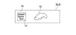
病理の分野一般においては、生体の臓器、組織、細胞、またはこれらの一部から、薄く切り取られたものが試料となる。連続切片として、組織等が、その厚さ方向に連続して複数切り取られる場合もある。切り取られた試料は、スライドガラスSLGに収められ、この試料15(図5参照)が顕微鏡による観察対象となる。本実施形態では、顕微鏡の機能を備えたスキャナ300によりスライドガラスSLGの試料15が読み取られ、これにより得られたデジタル画像が、スキャナ300あるいはサーバ200に記憶される。
In the general field of pathology, a sample obtained by thinly cutting a living organ, tissue, cell, or a part thereof is used as a sample. As a continuous section, a plurality of tissues or the like may be continuously cut in the thickness direction. The cut sample is stored in the slide glass SLG, and the sample 15 (see FIG. 5) is an observation object by a microscope. In the present embodiment, the
画像ピラミッド構造50は、スキャナ300により同じ1つの組織等の試料15から得られる同一の画像について、異なる複数の解像度により生成された画像群(試料の全体画像群)である。画像ピラミッド構造50の最下には、最も大きいサイズの画像が配置され、最上には最も小さいサイズの画像が配置される。最も大きいサイズの画像の解像度は、例えば50×50(Kpixel:キロピクセル)、あるいは40×60(Kpixel)である。最も小さいサイズの画像は、例えば256×256(pixel)、あるいは、256×512(pixel)である。
The
つまり、同じ表示部106が、これらの画像を例えば100%でそれぞれ表示(それらの画像のピクセル数と同じ物理的なドット数でそれぞれ表示)すると、最も大きいサイズの画像が最も大きく表示され、最も小さいサイズの画像が最も小さく表示される。ここで、図3では、その表示部106の表示範囲をDとして示している。
That is, when the
図4は、この画像ピラミッド構造50の画像群を生成するときの手順を説明するための図である。
FIG. 4 is a diagram for explaining a procedure for generating an image group of the
まず、スキャナ300により高解像度の画像として元画像が撮影される。この元画像が、図3で示した画像ピラミッド構造50の最下の画像である最も大きいサイズの画像に相当し、つまり最も高い解像度の画像となる。
First, an original image is taken as a high-resolution image by the
スキャナ300またはサーバ200は、図3に示すように、上記のように得られた最も大きいサイズの画像から、段階的に解像度を小さくした複数の画像を生成し、これらを例えば所定サイズの単位である「タイル」単位で記憶する。1タイルのサイズは、例えば256×256(pixel)である。このように生成された画像群が画像ピラミッド構造50を形成し、スキャナ300はこの画像ピラミッド構造50の情報を記憶する。実際には、スキャナ300は、それら異なる複数の解像度の画像と、解像度の情報とをそれぞれ対応付けて記憶すればよい。なお、画像ピラミッド構造50の生成及びその記憶は、図1に示したビューワ100が実行してもよい。
As shown in FIG. 3, the
これらの画像ピラミッド構造50を形成する全体画像群は、公知の圧縮方法により生成されてもよいし、例えば一般的なサムネイル画像を生成するときの公知の圧縮方法により生成されてもよい。あるいは、スキャナ300は、元画像の撮影倍率から順に撮影倍率を変えて、実際に複数の異なる解像度で試料を撮影し、これにより得られた全体画像群により画像ピラミッド構造50を作成してもよい。
The entire image group forming these
ビューワ100は、この画像ピラミッド構造50のシステムを採用するアプリケーションソフトウェアを用い、ユーザの入力部107を介した入力操作に応じて、画像ピラミッド構造50から所望の画像を抽出し、これを表示部106に出力する。具体的には、ビューワ100は、ユーザにより選択された任意の解像度の画像のうちの、ユーザにより選択された任意の部位の画像を表示する。このような処理により、ユーザは、観察倍率を変えながら試料15を観察しているような感覚を得ることができる。すなわち、ビューワ100は仮想顕微鏡として機能する。ここでの仮想的な観察倍率は、実際には解像度に相当する。
The
また、スキャナ300は、上記したように、試料15を保持したスライドガラスSLGの全体を所定の倍率(解像度)で撮影することにより、スライドガラスSLG全体の画像(以下、これをスライドガラス画像SLTという。)を生成する。図7の左側は、その撮影により得られたスライドガラス画像SLTの一例を示す。スキャナ300は、このスライドガラス画像SLTを自身の記憶部に保存するか、またはサーバ200に送信してサーバ200がこのスライドガラス画像SLTを保存する。このスライドガラス画像SLTがサムネイル画像として設定される。スライドガラス画像SLTが比較的低解像度で撮影された場合は、スライドガラス画像SLTがそのままサムネイル画像として設定される。
Further, as described above, the
あるいは、上記所定の倍率が比較的高解像度で撮影された場合、スライドガラス画像SLTが圧縮されて得られる画像が、サムネイル画像として設定されてもよい。 Alternatively, when the predetermined magnification is taken at a relatively high resolution, an image obtained by compressing the slide glass image SLT may be set as a thumbnail image.
図5に示すように、スライドガラスSLGの表面には、スライドガラスSLGの取り扱いの利便性を高めるために、ラベル情報17が記載されたラベル16が貼り付けられる場合がある。ラベル情報17は、その試料15に関連する情報であり、手書きまたは印刷により記載された、文字、記号または図形等の情報である。ラベル16は、典型的には、その貼り付け面が粘着性を有するいわゆる紙のシールである。
As shown in FIG. 5, a
ラベル情報の例としては、そのスライドガラスSLGが保持する組織または細胞の持ち主である患者を個別に識別するID(Identifier)が挙げられる。そのほか、ラベル情報は、染色情報、患者の検査日時またはスキャン日時等を示す情報であってもよい。例えばスライドガラスSLGの長手方向の左側にラベル16が貼り付けられている。そして、スライドガラスSLGの中央、あるいは、その中央から右側にわたって試料15が収容されている。
As an example of the label information, there is an ID (Identifier) for individually identifying a patient who owns a tissue or a cell held by the slide glass SLG. In addition, the label information may be information indicating staining information, patient examination date or scan date, or the like. For example, a
本実施形態に係るスキャナ300は、上記のように、ラベル16及び試料15の両画像を含む、スライドガラス画像SLTを生成する。本技術の基本的な特徴は、スキャナ300、サーバ200またはビューワ100が、このようなスライドガラス画像SLTを、サムネイル画像として出力することにある。
As described above, the
また、スキャナ300またはサーバ200は、上記のように作成されたスライドガラス画像SLTと、これに対応する実画像データ(上記画像ピラミッドを形成する全体画像群)とを関連付けて記憶する。これにより、後述するように、ビューワ100はそのスライドガラス画像SLTを示すサムネイル画像を表示することができる。ユーザがそのサムネイル画像にアクセスすると、実画像データを閲覧することが可能な所定のアプリケーションソフトウェアが起動する。これにより、ユーザは、実画像データを観察することができる。
Further, the
以下では、スライドガラス画像SLTの記憶に関連する処理及び表示に関連する処理について、いくつかの実施形態を説明する。各実施形態において、同様の処理についての説明を簡略化または省略する。 Below, some embodiment is described about the process relevant to memory | storage of the slide glass image SLT, and the process relevant to a display. In each embodiment, description of similar processing is simplified or omitted.
[スライドガラス画像SLTの記憶処理] [Storage processing of slide glass image SLT]
1.サーバ200がスライドガラス画像SLTを記憶する形態
(A)ラベル画像が暗号化されない場合の処理
1. Form in which
スライドガラス画像SLTの記憶処理において、ラベル画像の切り出し画像(切り出しラベル画像)が暗号化されない場合について説明する。 The case where the cutout image (cutout label image) of the label image is not encrypted in the storage processing of the slide glass image SLT will be described.
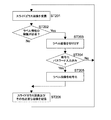
図6は、スキャナ300から送信されたスライドガラス画像SLTをサーバ200が受信した場合に、サーバ200がこれを記憶する処理を示すフローチャートである。以降で説明する処理は、典型的にはハードウェア及びソフトウェアの協働により実現される。
FIG. 6 is a flowchart illustrating a process in which the
サーバ200は、スキャナ300から送信されたスライドガラス画像SLTを受信する(ステップ101)。この場合、サーバ200はスライドガラス画像SLTを一時的にメモリに記憶する(記憶部)。サーバ200は、スライドガラス画像SLT内のラベル情報の隠匿(秘匿)が必要か否かを判定する(ステップ102)。ステップ102の判定処理は、サーバ200が予め定められたアルゴリズムにしたがって動的に実行すればよい。
The
隠匿が不要な場合とは、例えばラベル情報に個人情報(例えば患者の名前等)が含まれない場合や、ラベル情報が記載されていない場合等である。サーバ200は、その個人情報である名前を文字認識技術により読み取り、その読み取った名前を、人の名前のデータベースと照合させたり、あるいはその他のアルゴリズムによって、ラベル情報に個人情報が含まれる否かを判定することができる。
The case where concealment is unnecessary is, for example, a case where the label information does not include personal information (for example, the name of a patient) or a case where the label information is not described. The
なお、現在の文字認識処理は、OCR(Optical Character Reader(Recognition))のように光学的に対象情報を読み取る工程(すなわち対象物をスキャナで読み取る工程)を含む場合に限られず、テキスト情報を含まない画像内の文字をテキスト情報に変換する技術もある。 Note that the current character recognition process is not limited to the case where it includes a step of optically reading target information (ie, a step of reading the target with a scanner) like OCR (Optical Character Reader (Recognition)), and includes text information. There is also a technique for converting characters in a non-image into text information.
また、「動的に実行する」場合の他の例として、人間が、個人情報が含むか否かの2値情報を予めそのラベルに記載しておき、サーバ200がそのラベル情報のうち2値情報を読み取る形態が挙げられる。
As another example of the case of “dynamically executing”, a person previously describes binary information indicating whether or not personal information is included in the label, and the
あるいはステップ102の判定処理は、人間がその判定処理を行う等、静的に実行されてもよい。
Alternatively, the determination process in
サーバ200は、ステップ102でNOの場合、そのスライドガラス画像SLTをそのままサムネイル画像(マクロ画像)として記憶する(ステップ104)。
If NO in
<ラベル画像の切り出し処理の形態>
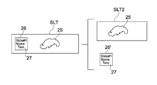
サーバ200は、ステップ102でYESの場合、図7に示すようにそのスライドガラス画像SLTに含まれるラベル画像26及び試料画像25のうち、ラベル画像26を切り出すことにより、切り出しラベル画像26’を生成する(ステップ103)。
<Form of Label Image Cutout Process>
If YES in
ステップ103の切り出し処理において、スライドガラス画像SLTの表面のうちラベル画像26が設けられる領域をサーバ200が認識するためのアルゴリズム(つまり、切り出し処理のアルゴリズム)としては、次のような方法が挙げられる。
In the cutout process in
(1)スライドガラス画像SLTのうち、所定の領域をラベルの領域として認識する。
例えば、試料の染色工程の際、ラベルが自動で貼付されていたり、または、手動である場合でも貼り付け位置が決まっているような場合は、ラベルの領域を固定位置及び固定サイズとする。
(1) A predetermined area in the slide glass image SLT is recognized as a label area.
For example, in the case of a sample staining step, when the label is automatically attached or when the attachment position is determined even when it is manual, the area of the label is set as a fixed position and a fixed size.
(2)スライドガラス画像SLTのうち、エッジ検出処理によりラベル画像26を認識する。
例えば2値化された輝度値の境界を検出する処理等、公知のエッジ検出のアルゴリズムを用いることにより、ラベルの領域を自動検出が可能である。
(2) The
For example, the label area can be automatically detected by using a known edge detection algorithm such as a process of detecting a binarized luminance value boundary.
(3)スライドガラス画像SLTのうち、ラベル16に記載されたラベル情報17を文字認識処理により読み取る。
これは、上記した文字認識処理のアルゴリズムを用いて、ラベル情報17としての文字が記載されている領域の外接枠(例えば矩形の枠)を、ラベル領域として認識する方法である。
(3) The
This is a method of recognizing a circumscribed frame (for example, a rectangular frame) of an area in which characters as the
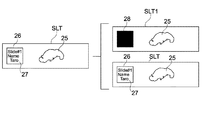
また、サーバ200は、ステップ103の処理に付随して、次の処理を実行する。サーバ200は図7に示すように、オリジナルのスライドガラス画像SLTのラベル画像を隠匿するためのカバー画像28を、ラベル画像26上に合成することにより、ラベル情報17が隠匿されたスライドガラス画像を生成する。ここで説明の便宜上、このようにラベル情報17が隠匿されたスライドガラス画像を、ラベル画像が除去された除ラベルスライドガラス画像(除ラベルスライド板画像)という。
In addition, the
図7に示した例では、ラベル画像26を隠匿するためのカバー画像28は、黒単色で塗りつぶされ画像となっている。もちろん、カバー画像28は、黒一色の画像に限られず、他の色(単色または複数色)であってもよいし、模様または図柄等を含む画像であってもよい。
In the example shown in FIG. 7, the
模様または図柄を含む画像としては、モザイクによりラベル画像26をぼかした画像や、鍵の絵等が挙げられる。鍵の絵は、後述するように、ラベル画像26が暗号化される場合に適用されることが望ましい。
Examples of the image including a pattern or a pattern include an image in which the
<画像の記憶処理の形態>
サーバ200によるステップ104における画像の記憶処理の形態は、次のように3つの形態がある。
<Mode of image storage processing>
There are three forms of image storage processing in
(1)サーバ200は、ステップ103で生成された切り出しラベル画像26’と、元のスライドガラス画像SLTとを関連付けて(紐付けして)、これらを別々のファイルとして記憶する。
(1) The
(2)図8に示すように、サーバ200は、スライドガラス画像SLTのうちラベル画像26の領域を除く、少なくとも試料画像を含む除ラベルスライドガラス画像SLT2と、ステップ103で生成された切り出しラベル画像26'とを関連付けて、これらを別々のファイルとして記憶する。
(2) As shown in FIG. 8, the
図8に示す形態の場合、サーバ200は、元のスライドガラス画像SLTを、これら切り出しラベル画像26’及び除ラベルスライドガラス画像SLT2を含む画像に関連付けて記憶してもよい。
In the case of the form shown in FIG. 8, the
(3)あるいは、図9に示すように、サーバ200は、除ラベルスライドガラス画像SLT1と、元のスライドガラス画像SLTとを関連付けて、これらを別々のファイルとして記憶する。この場合、ステップ103で生成された切り出しラベル画像26’は、これら除ラベルスライドガラス画像SLT1及び元のスライドガラス画像SLTに関連付けて記憶されればよい。この場合、サーバ200は、ビューワの要求に応じて、画像SLT及びSLT1を選択的に出力することができる。
(3) Alternatively, as shown in FIG. 9, the
サーバ200は、後述するように、ビューワ100によるサムネイル画像の取得の要求に応じて、以上のように保存されたスライドガラス画像SLTや除ラベルスライドガラス画像SLT1等を、ビューワ100に送信することが可能な状態をとる。
As will be described later, the
(B)ラベル画像を暗号化することが可能な場合の処理 (B) Processing when the label image can be encrypted
次に、切り出しラベル画像26’が暗号化され得る場合についての記憶処理を説明する。図10は、その処理を示すフローチャートである。 Next, the storage process when the cutout label image 26 'can be encrypted will be described. FIG. 10 is a flowchart showing the processing.
ステップ201〜203の処理は、図6に示したステップ101〜103と同様である。
The processing in steps 201 to 203 is the same as that in
サーバ200は、暗号化のためのパスワードが入力されたか否かを判定する(ステップ204)。ユーザによるパスワードの入力を、例えばスキャナ300が所定のタイミングで受け付け、そのパスワード情報をサーバ200に送信すればよい。所定のタイミングとは、例えばスキャナ300によるスライドガラスSLGの読み取りの前または後とすればよい。
The
ステップ204でNOの場合、サーバ200はラベル画像26を暗号化できないため、ラベル画像を破棄(削除)してもよい。
If NO in step 204, the
ステップ204でYESの場合、サーバ200は、ラベル画像26を暗号化することにより、図11A及びBに示すように、暗号化切り出しラベル画像26’’を取得する(ステップ205)。暗号化処理では、例えばDES(Data Encryption Standard)やAES(Advanced Encryption Standard)等のアルゴリズムが用いられればよい。
If YES in step 204, the
サーバ200は、上で説明したように、図7〜9のうちいずれか1つの方法によって、暗号化された切り出しラベル画像26’’を保存する(ステップ206)。図7及び8にそれぞれ対応する図を、図11A及びBに示した。
As described above, the
2.スキャナ300がスライドガラス画像SLTを記憶する形態
2. Form in which
上記1.では、サーバ200がスキャナ300から送信されたスライドガラス画像SLTを受信し、これを記憶する処理について説明した。この2.では、スキャナ300がスライドガラス画像SLTを記憶する形態について説明する。
Above 1. In the above description, the
(A)ラベル画像が暗号化されない場合の処理 (A) Processing when the label image is not encrypted
図12は、上記1.の(A)と同様に、切り出しラベル画像26’が暗号化されない場合の記憶処理を示すフローチャートである。スキャナ300が記憶する処理は、基本的には、サーバ200が記憶する処理と同様である。
FIG. As in (A), the storage label processing when the
スキャナ300は、試料の画像の撮影(実画像データの生成)とは別に、上記したようにスライドガラスSLG全体の画像を撮影することにより、ラベル画像26及び試料画像25を含むスライドガラス画像SLTを取得する(ステップ301)。そして、スキャナ300は、図6に示したステップ102と同様の処理を実行する(ステップ302)。
The
スキャナ300は、ステップ302でYESの場合、スライドガラス画像SLTからラベル画像26を切り出すことにより、切り出しラベル画像26’を生成する(ステップ303)。切り出し処理のアルゴリズムは、上記したアルゴリズムでよい。
If YES in step 302, the
スキャナ300は、生成された画像をサーバ200に送信する(ステップ304)。この場合、スキャナ300は、生成された画像を一時的にメモリに記憶し(記憶部)、そしてサーバ200に出力する(出力部)。
The
ステップ304では、ステップ302でNOの場合は、スキャナ300は、ステップ301で撮影されたスライドガラス画像SLTをサムネイル画像として送信する。一方、ステップ303を経由する場合、スキャナ300は、切り出しラベル画像26'と除ラベルスライドガラス画像SLT1(SLT2)とを関連付け、これらの画像をサムネイル画像としてサーバ200に送信する。
In step 304, if NO in step 302, the
(B)ラベル画像が暗号化される場合の処理 (B) Processing when label image is encrypted
図13は、スキャナ300が切り出しラベル画像26’を暗号化する場合の処理を示すフローチャートである。この処理は、基本的には、図10に示した処理と同様である。
FIG. 13 is a flowchart showing processing when the
ステップ406では、スキャナ300は、図11A及びBに示したように、暗号化された切り出しラベル画像26'と、除ラベルスライドガラス画像SLT1等とを関連付け、これらの画像をサムネイル画像としてサーバ200に送信する。
In step 406, as shown in FIGS. 11A and 11B, the
[スライドガラス画像SLTの表示処理] [Display processing of slide glass image SLT]
次に、ビューワ100によるサムネイル画像の表示処理について説明する。図14は、その処理を示すフローチャートである。
Next, display processing of thumbnail images by the
ビューワ100は、サーバ200に、上記スライドガラス画像SLT及び実画像データにアクセスして閲覧するための、ファイル一覧の情報の取得を要求する(要求信号を生成し(生成部)、サーバ200に出力する)(ステップ501)。つまり、ビューワ100は、主に1つまたは複数のスライドガラス画像SLTの取得の要求信号を出力する。ビューワ100は、ユーザによるビューワ100への操作入力にしたがって要求信号を生成してもいし、その他所定のアルゴリズムにしたがってそれを生成してもよい。
The
サーバ200は、その要求信号を受信したことに基づき、その取得要求で指定された1つまたは複数のスライドガラス画像SLTを送信する。この処理では、サーバ200は、図7〜9及び11A及びBのうち1つの形態で保存されたスライドガラス画像SLTをビューワ100に送信する。図14に示した処理では、説明を分かりやすくするために、以下のような前提とする。すなわち、サーバ200が、自身の記憶デバイスに記憶している各種のスライドガラス画像等をビューワ100に送信し、ビューワ100が所定のアルゴリズムにしたがって、そのスライドガラス画像に種々のデータに加工して(例えば暗号化され情報を復号して)表示する形態を説明する。
Based on the reception of the request signal, the
図15及び16は、ビューワ100により表示され得るスライドガラス画像SLT(加工及び未加工の画像を含む)の各種の形態を示す。特に、図15は、上記1.(A)または2.(A)で説明したように、ラベル画像が暗号化されない場合の画像を示す。図16は、上記1.(B)または2.(B)で説明したように、ラベル画像が暗号された場合の画像を示す。これらのうちどのスライドガラス画像SLT(サムネイル画像)を表示するかは、図14に示したフローチャートの判定処理の結果によって変わる。
15 and 16 show various forms of a slide glass image SLT (including processed and unprocessed images) that can be displayed by the
ビューワ100は、スライドガラス画像SLTを取得(受信)すると(ステップ502)、そのスライドガラス画像SLTのラベル情報の隠匿が必要か否かを判定する(ステップ503)。ステップ503の処理は、図6等に示したステップ102において説明した「動的」処理と同様である。
When the
ステップ503でNOの場合、ビューワ100は、受信したスライドガラス画像SLT、すなわち元のスライドガラス画像SLT(図15のAで示す画像)をそのままサムネイル画像として表示する(ステップ508)。この場合、ビューワ100のCPU101及び入出力インターフェース105等は、表示部106にサムネイル画像を出力する出力部として機能する(このことは、後述するステップ509及び510についても同様である。)。
If NO in step 503, the
なお、ステップ503でNOの場合であって、ラベル画像26が暗号化されている場合でも、ステップ508において、ビューワ100はそれを復号し、元のスライドガラス画像SLT(図16のAで示す画像)を表示してもよい。
Note that even in the case of NO in step 503 and the
ステップ503においてYESの場合、ビューワ100は、そのスライドガラス画像SLTのうちラベル画像26が設けられる領域(ラベル領域)の画像を表示するか否かを判定する(ステップ504)。この判定処理の結果は、例えばビューワ100が持つアプリケーションソフトウェアの設定によって変わればよい。例えば、そのラベル領域を表示しない設定になっている場合(ステップ504のNO)、除ラベルスライドガラス画像SLT1(図15のBで示す画像)を生成して表示する(ステップ509)。一方、そのラベル領域を表示する設定になっている場合(ステップ504のYES)、ビューワ100は次のステップ505へ進む。
If YES in step 503, the
なお、図15のCに示す画像は、個人情報を含むラベル情報が記載されたスライドガラス画像SLTである。このように、ビューワは、ステップ505以降の処理を経ないで、スライドガラス画像SLTをそのままサムネイル画像として表示することもできるような、設定を持っていてもよい。 Note that the image shown in FIG. 15C is a slide glass image SLT on which label information including personal information is described. In this way, the viewer may have a setting that allows the slide glass image SLT to be displayed as a thumbnail image without undergoing the processing from step 505 onward.
ステップ509では、サーバ200が除ラベルスライドガラス画像SLT1をビューワ100に送り、ビューワ100がこれを受信して表示してもよい(このことは、後述のステップ510についても同様である。)。
In step 509, the
ステップ504でYESの場合、ビューワ100は、画像を復号するためのパスワードが入力済みであるか否かを判定する(ステップ505)。例えばこれは、ビューワ100が持つ画像を閲覧するアプリケーションソフトウェア上でサーバ200にログインする時や、このソフトウェアを使用する時のユーザID及びパスワードがユーザにより入力されているか否かの判定処理である。もちろん、ビューワ100が画像の表示を要求するごとにパスワードの入力画面を表示し、ユーザにパスワードを入力させてもよい。
If YES in step 504, the
ステップ505においてパスワードが入力済みでない場合、ステップ509に進む。この場合、ビューワ100は、除ラベルスライドガラス画像SLT1として、鍵の絵が合成されたスライドガラス画像SLT(図16のBで示す画像)を、サムネイル画像として表示する。これにより、ラベル情報が暗号化により守られていることを明示することができる。
If the password has not been entered in step 505, the process proceeds to step 509. In this case, the
一方、ステップ505においてパスワードが入力済みである場合、ビューワ100は、ラベル情報を含む、暗号化された切り出しラベル画像26’’をサーバ200から取得し、パスワードを用いて画像を復号する(ステップ506)。この場合、サーバ200は、先に送信したスライドガラス画像SLTに関連付けられた暗号化された切り出しラベル画像26’’(図11A及びB等参照)を、ビューワ100に送信する。
On the other hand, if the password has already been input in step 505, the
復号化に成功しなかった場合(ステップ507のNO)、ビューワ100は、ステップ509に進み、パスワードが入力済みでない場合の処理と同様に、ラベル領域に鍵の絵の画像が合成された除ラベルスライドガラス画像(図16のCで示す画像)を、サムネイル画像として表示する。復号化に成功しなかった場合とは、例えばパスワードが誤入力された場合である。
If the decryption is not successful (NO in step 507), the
復号化に成功した場合(ステップ507のYES)、ビューワ100は、除ラベルスライドガラス画像のラベル領域に、復号された切り出しラベル画像26’を合成することにより、元のスライドガラス画像SLT(図16のDで示す画像)を復元する。そして、ビューワ100は、復元された元のスライドガラス画像SLTを、サムネイル画像として表示する(ステップ510)。
If the decoding is successful (YES in step 507), the
図17は、ビューワ100が表示するサムネイル画像の一覧の画面の例を示す。この例では、例えば1つのフォルダ40内に複数のスライドガラス画像SLTが、サムネイル画像として表示されており、すべてのスライドガラス画像SLT内のラベル画像26が表示されている。ユーザは、このサムネイル画像のファイルにアクセス(例えばダブルクリック)することをトリガーとして、ビューワ100は、サーバ200にそれに対応する実画像データの送信を要求する。そして、サーバ200はこれに応じて実画像データをビューワ100に送信する。
FIG. 17 shows an example of a thumbnail image list screen displayed by the
[本技術による効果] [Effects of this technology]
以上のように、本技術によれば、試料画像25及びラベル画像26の両方を含むスライドガラス画像SLTが、サムネイル画像として表示可能となるので、ユーザは、実際のスライドガラスSLGをそのまま画面上で観ることができる。したがって、ユーザの直感性が高められ、便利であり使用性が向上する。具体的には、ユーザは、所望のファイルを容易に選択できるようになる。
As described above, according to the present technology, since the slide glass image SLT including both the
また、本技術は、以下のような問題も解決することができる。 The present technology can also solve the following problems.
図18A〜Cは、本技術と対比される参考例に係る、実際のスライドガラスSLGと、このスライドガラスSLGからスキャンにより得られるサムネイル画像を示す。 18A to 18C show an actual slide glass SLG and a thumbnail image obtained by scanning from the slide glass SLG according to a reference example compared with the present technology.
例えば図18Aでは、スライドガラスSLGには連続切片に分割された試料15が収められている。しかし、このサムネイル画像T1は、それらのうち1つの試料のみが撮影され、これが画像データ化されたものである。このような場合、ユーザは、サムネイル画像T1に表された試料の画像55が、複数の連続切片の試料15のうちどれを示しているのかが分からない。あるいは、ユーザは、この試料の画像55が連続切片から得られたものであることも分からない場合もある。これに対し、本技術によれば、ユーザは、試料画像25及びラベル画像26の両方を含むスライドガラス画像SLTを観ることができるので、上記のような問題を解消できる。
For example, in FIG. 18A, the
図18Bに示すように、複数のスライドガラスSLG間で、それぞれ試料15a及び15bのサイズがばらばらなので、それらの試料の撮影時の撮影倍率もばらばらになる場合がある。ところが、図のように、サムネイル画像T2及びT3としてそれぞれ得られる試料の画像55a及び55bのサイズがほぼ同じとして表示されると、それらの画像が相似形である場合には、ユーザはその試料のサイズの比較できない。
As shown in FIG. 18B, since the sizes of the
図18Cに示すように、実際のスライドガラスSLGで収められた試料15が右端で切れている場合に、ユーザがそのサムネイル画像T4を観た時に、これが、撮影ミスによるのか、実際に右端で切れているのかを判断できない。このため、無駄な再スキャンが行われる場合がある。
As shown in FIG. 18C, when the
本技術によればこれらの図18B及びCで示した問題も解決することができる。すなわち、ユーザは、実画像データを表示する前に、サムネイル画像を観ることにより、試料のサイズを確認できる。また、無駄な再スキャンが行われることを防止できる。 According to the present technology, the problems shown in FIGS. 18B and 18C can also be solved. That is, the user can confirm the size of the sample by viewing the thumbnail image before displaying the actual image data. In addition, it is possible to prevent unnecessary rescanning.
また、本技術によれば、例えば図7、8、11A及び11Bに示したように、除ラベルスライドガラス画像と、切り出しラベル画像26’とが、別ファイルに分けて保存されるので、情報の管理上、有用である。
Further, according to the present technology, for example, as shown in FIGS. 7, 8, 11A, and 11B, the removal label slide glass image and the
これに対し、本技術によれば、ラベル情報17に個人情報等が含まれる場合であっても、ラベル画像が暗号化されるので、そのラベル画像のデータがコピーされても、個人情報の漏洩を防止でき、セキュリティを高めることができる。
On the other hand, according to the present technology, even if the
例えば、ユーザがファイルの選択段階で、ラベル情報を一括して表示と非表示とを切り替えることも考えられるが、これだけでは、個人情報の漏洩を防止することは困難である。しかしながら本技術では、ラベル領域に隠匿用のカバー画像28が合成され得るので、暗号化されたラベル画像が復号されない限り、画面にラベル画像が表示されることはない。これにより、セキュリティを向上させることができる。
For example, it is conceivable that the user switches between displaying and hiding the label information at a file selection stage, but it is difficult to prevent leakage of personal information only with this. However, in the present technology, since the
[その他の実施形態] [Other embodiments]
本技術は、以上説明した実施形態に限定されず、他の種々の実施形態を実現することができる。 The present technology is not limited to the embodiments described above, and other various embodiments can be realized.
上記実施形態では、スキャナ300が、スライドガラスSLGの表面に照明光を照射して、その光の反射により対象像を撮影した。しかし、スキャナ300は、それにより得られたスライドガラス画像SLTを取得する他、スライドガラスSLGの表面の反対側である裏面側から照明光を照射し、その透過光を対象像として撮影してもよい。スライドガラスSLGに収められた試料15は照明光を通すほど薄く切り取られているため、その像を表面側から撮影することができる。一方、ラベル領域はラベル16が貼り付けられているため影になるので、その撮影により、スキャナ300は、除ラベルスライドガラス画像を取得することができる。この場合、スキャナ300またはサーバ200は、通常のスライドガラス画像SLTと除ラベルスライドガラス画像とを関連付けて記憶しておけばよい。このような実施形態によれば、ラベル画像の切り出し処理のアルゴリズムが不要となる。
In the above embodiment, the
図14に示した処理において、サーバ200が、ステップ506の復号処理及びステップ510の合成処理等を実行し、合成処理により得られたスライドガラス画像SLTをビューワ100に送信してもよい。
In the process illustrated in FIG. 14, the
本実施形態に係る情報処理装置は、スキャナ300、サーバ200及びビューワ100の3つの種類を有していたが、例えばスキャナ300とサーバ200とが物理的に一体となった形態でもよい。この場合、スキャナ300が撮影により取得した各種画像を、自身の記憶デバイスに記憶しておくことができ、ビューワ100の要求に応じて画像をビューワ100に送信するサーバ200としても機能することがでる。
The information processing apparatus according to the present embodiment has the three types of the
上記実施形態において、例えば文字認識処理により、ラベル情報が読み取られ、テキスト情報が作成された場合は、スキャナ300またはサーバ200は、ラベル画像を暗号化する処理に加え、そのテキスト情報(ラベル情報)を暗号化してもよい。
In the above embodiment, when label information is read and text information is created by, for example, character recognition processing, the
以上説明した各形態の特徴部分のうち、少なくとも2つの特徴部分を組み合わせることも可能である。 It is also possible to combine at least two feature portions among the feature portions of each embodiment described above.
本技術は以下のような構成もとることができる。
(1) 表面を有するスライド板であって試料を保持し前記試料に関連するラベル情報が記載されたラベルが前記表面に設けられたスライド板が撮影されることにより得られる、前記試料及び前記ラベルの両画像を含む、前記スライド板の画像を記憶可能な記憶部と、
前記スライド板の画像をサムネイル画像として出力可能な出力部と
を具備する情報処理装置。
(2)(1)に記載の情報処理装置であって、
前記スライド板の画像内の前記ラベル画像を切り出すことにより切り出しラベル画像を生成する処理部をさらに具備し、
前記記憶部は、前記スライド板画像内の少なくとも前記試料画像を含み前記ラベル画像が除去された除ラベルスライド板画像と、前記切り出しラベル画像とを関連付けて記憶する
情報処理装置。
(3)(2)に記載の情報処理装置であって、
前記処理部は、前記スライド板画像のうち前記ラベル画像を隠匿するためのカバー画像を、前記スライド板画像の前記ラベル画像上に合成することにより、前記除ラベルスライド板画像を生成し、
前記記憶部は、前記除ラベルスライド板画像と、前記切り出しラベル画像とを関連付けて記憶する
情報処理装置。
(4)(2)に記載の情報処理装置であって、
前記処理部は、さらに、前記切り出しラベル画像を暗号化可能であり
前記記憶部は、前記除ラベルスライド板画像と、前記暗号化された暗号化切り出しラベル画像とを関連付けて記憶する
情報処理装置。
(5)(3)に記載の情報処理装置であって、
前記処理部は、さらに、前記切り出しラベル画像を暗号化可能であり、
前記処理部は、前記除ラベルスライド板画像と、前記暗号化された暗号化切り出しラベル画像とを関連付けて記憶する
情報処理装置。
(6)(4)または(5)に記載の情報処理装置であって、
前記処理部は、復号パスワードに基づいて前記暗号化切り出しラベル画像を復号可能であり、復号された前記切り出しラベル画像を、前記除ラベルスライド板画像内の前記ラベルが設けられる領域に合成することにより、前記スライド板画像を復元する
情報処理装置。
(7)(2)に記載の情報処理装置であって、
前記処理部は、前記スライド板画像のうち前記ラベル画像を隠匿するためのカバー画像を、前記スライド板画像の前記ラベル画像上に合成することにより、前記除ラベルスライド板画像を生成し、
前記記憶部は、前記除ラベルスライド板画像を、元の前記スライド板画像に関連付けて記憶する
情報処理装置。
(8)(7)に記載の情報処理装置であって、
前記出力部は、前記元のスライド板画像と前記除ラベルスライド板画像とを選択的に出力する
情報処理装置。
(9)(2)から(8)のうちいずれか1つに記載の情報処理装置であって、
前記処理部は、前記スライド板の画像のうち、所定の領域をラベル領域として切り出す
情報処理装置。
(10)(2)から(8)のうちいずれか1つに記載の情報処理装置であって、
前記処理部は、前記スライド板の画像のうち、エッジ検出処理により前記ラベル画像を切り出す
情報処理装置。
(11)(2)に記載の情報処理装置であって、
前記処理部は、前記スライド板の画像のうち前記ラベル情報を、文字認識処理により読み取る
情報処理装置。
(12)(11)に記載の情報処理装置であって、
前記処理部は、さらに、前記読み取られた前記ラベル情報を暗号化する
情報処理装置。
(13)(1)に記載の情報処理装置であって、
前記スライド板が透明である場合、前記記憶部は、前記スライド板の前記表面の反対側である裏面側から、前記スライド板に照明光が照射されて前記表面側からの前記スライド板の撮影により得られる、前記試料画像及び前記ラベルの影によって前記ラベル情報が隠匿された除ラベルスライド板画像を、前記スライド板画像に関連付けて記憶する
情報処理装置。
(14) 表面を有するスライド板であって試料を保持し前記試料に関連するラベル情報が記載されたラベルが前記表面に設けられたスライド板を撮影可能であり、前記撮影により、前記試料及び前記ラベルの両画像を含む、前記スライド板の画像を取得可能な取得部と、
前記スライド板の画像を送信可能な送信部と
を含むスキャナ装置と、
前記スキャナ装置の前記送信部から送信された前記スライド板画像を、サムネイル画像として記憶可能な記憶部と、
前記サムネイル画像の取得を要求する要求信号を受信可能な受信部と、
前記要求信号を受信したことに基づき、前記記憶されたサムネイル画像を送信可能な送信部と
を含むサーバ装置と、
前記要求信号を生成可能な生成部と、
前記生成された要求信号を前記サーバ装置に送信可能な送信部と、
前記サーバ装置から送信される前記サムネイル画像を受信可能な受信部と
を含むビューワ装置と
を具備する情報処理システム。
(15) 表面を有するスライド板であって試料を保持し前記試料に関連するラベル情報が記載されたラベルが前記表面に設けられたスライド板が撮影されることにより得られる、前記試料及び前記ラベルの両画像を含む、前記スライド板の画像を、サムネイル画像として記憶可能な記憶部と、
前記サムネイル画像の取得を要求する要求信号を受信可能な受信部と、
前記要求信号を受信したことに基づき、前記記憶されたサムネイル画像を送信する送信部と
を含むサーバ装置と、
前記要求信号を生成可能な生成部と、
前記生成された要求信号を前記サーバ装置に送信可能な送信部と、
前記サーバ装置から送信される前記サムネイル画像を受信可能な受信部と
を含むビューワ装置と
を具備する情報処理システム。
(16) 表面を有するスライド板であって試料を保持し前記試料に関連するラベル情報が記載されたラベルが前記表面に設けられたスライド板が撮影されることにより得られる、前記試料及び前記ラベルの両画像を含む、前記スライド板の画像を、サムネイル画像として記憶し、
前記サムネイル画像を出力する
情報処理方法。
The present technology can be configured as follows.
(1) The sample and the label, which are obtained by photographing a slide plate having a surface, which holds the sample and has a label on which label information related to the sample is provided. A storage unit capable of storing an image of the slide plate, including both images of
An information processing apparatus comprising: an output unit capable of outputting an image of the slide plate as a thumbnail image.
(2) The information processing apparatus according to (1),
A processing unit that generates a cutout label image by cutting out the label image in the image of the slide plate;
The storage unit stores an associated label-removed slide plate image including at least the sample image in the slide plate image from which the label image has been removed and the cut-out label image in association with each other.
(3) The information processing apparatus according to (2),
The processing unit generates the removed label slide plate image by combining a cover image for concealing the label image among the slide plate images on the label image of the slide plate image,
The storage unit stores the label removal slide image and the cut label image in association with each other.
(4) The information processing apparatus according to (2),
The processing unit is capable of further encrypting the cutout label image, and the storage unit stores the removed label slide plate image and the encrypted encrypted cutout label image in association with each other.
(5) The information processing apparatus according to (3),
The processing unit can further encrypt the cut-out label image,
The processing unit stores the correlated label slide plate image and the encrypted encrypted cutout label image in association with each other.
(6) The information processing apparatus according to (4) or (5),
The processing unit is capable of decrypting the encrypted cutout label image based on a decryption password, and synthesizes the decoded cutout label image into an area where the label is provided in the removed label slide plate image. An information processing apparatus for restoring the slide plate image.
(7) The information processing apparatus according to (2),
The processing unit generates the removed label slide plate image by combining a cover image for concealing the label image among the slide plate images on the label image of the slide plate image,
The storage unit stores the removed label slide plate image in association with the original slide plate image.
(8) The information processing apparatus according to (7),
The output unit selectively outputs the original slide plate image and the removed label slide plate image.
(9) The information processing apparatus according to any one of (2) to (8),
The processing unit cuts out a predetermined area as a label area from the image of the slide plate.
(10) The information processing apparatus according to any one of (2) to (8),
The information processing apparatus, wherein the processing unit cuts out the label image by edge detection processing from an image of the slide plate.
(11) The information processing apparatus according to (2),
The processing unit reads the label information from the image of the slide plate by a character recognition process.
(12) The information processing apparatus according to (11),
The processing unit further encrypts the read label information.
(13) The information processing apparatus according to (1),
When the slide plate is transparent, the storage unit irradiates the slide plate with illumination light from the back side opposite to the front surface of the slide plate, and shoots the slide plate from the front side. An information processing apparatus that stores the obtained label image with the label information concealed by the sample image and the shadow of the label in association with the slide plate image.
(14) A slide plate having a surface, which holds a sample and is capable of photographing a slide plate provided with a label on which label information related to the sample is described. An acquisition unit capable of acquiring an image of the slide plate including both images of a label;
A scanner device including: a transmission unit capable of transmitting an image of the slide plate;
A storage unit capable of storing the slide plate image transmitted from the transmission unit of the scanner device as a thumbnail image;
A receiving unit capable of receiving a request signal for requesting acquisition of the thumbnail image;
A server device including: a transmission unit capable of transmitting the stored thumbnail image based on reception of the request signal;
A generation unit capable of generating the request signal;
A transmission unit capable of transmitting the generated request signal to the server device;
An information processing system comprising: a viewer device including: a receiving unit capable of receiving the thumbnail image transmitted from the server device.
(15) The sample and the label, which are obtained by photographing a slide plate having a surface, which holds a sample and has a label on which label information related to the sample is provided. A storage unit capable of storing images of the slide plate including both images as thumbnail images;
A receiving unit capable of receiving a request signal for requesting acquisition of the thumbnail image;
A server device including: a transmission unit that transmits the stored thumbnail image based on reception of the request signal;
A generation unit capable of generating the request signal;
A transmission unit capable of transmitting the generated request signal to the server device;
An information processing system comprising: a viewer device including: a receiving unit capable of receiving the thumbnail image transmitted from the server device.
(16) The sample and the label, which are obtained by photographing a slide plate having a surface, which holds the sample and has a label on which label information related to the sample is described is provided on the surface The images of the slide plate including both images are stored as thumbnail images,
An information processing method for outputting the thumbnail image.
SLT1、SLT2…除ラベルスライドガラス画像
15…試料
17…ラベル情報
25…試料画像
26…ラベル画像
28…カバー画像
100…ビューワ
101…CPU
102…ROM
105…入出力インターフェース
106…表示部
108…記憶部
109…通信部
200…サーバ
300…スキャナ
SLT1, SLT2 ... Removed
102 ... ROM
105 ... Input /
Claims (14)
前記スライド板の画像であるスライド板画像を出力可能な出力部と、
前記スライド板画像内の前記ラベル画像を切り出すことにより切り出しラベル画像を生成する処理部とを具備し、
前記出力部は、サムネイル画像として、元の前記スライド板画像と、前記スライド板画像内の少なくとも前記試料画像を含み前記ラベル画像の切り出しにより前記ラベル画像が除去された除ラベルスライド板画像とを選択的に出力する
情報処理装置。 A sample image, which is an image of the sample , obtained by photographing a slide plate having a surface, which holds the sample and has a label on which the label information related to the sample is described is provided on the surface And a storage unit that can store an image of the slide plate, including a label image that is an image of the label information ;
A slide plate image output possible output section is an image of the slide plate,
A processing unit that generates a cutout label image by cutting out the label image in the slide plate image;
The output unit selects, as thumbnail images, the original slide plate image and a removed label slide plate image that includes at least the sample image in the slide plate image and from which the label image has been removed by cutting out the label image. Output information processing device.
前記記憶部は、前記除ラベルスライド板画像及び前記元のスライド板画像と、前記切り出しラベル画像とを関連付けて記憶する
情報処理装置。 The information processing apparatus according to claim 1,
Before term memory unit, before and Kijo label slide plate image and the original slide plate image, the information processing apparatus in association with said cutout label image.
前記処理部は、前記スライド板画像のうち前記ラベル画像を隠匿するためのカバー画像を、前記スライド板画像の前記ラベル画像上に合成することにより、前記除ラベルスライド板画像を生成する
情報処理装置。 An information processing apparatus according to claim 2,
The processing unit is configured to generate the removed label slide plate image by combining a cover image for concealing the label image in the slide plate image on the label image of the slide plate image. .
前記処理部は、さらに、前記切り出しラベル画像を暗号化可能であり、
前記記憶部は、前記除ラベルスライド板画像及び前記元のスライド板画像と、前記暗号化された暗号化切り出しラベル画像とを関連付けて記憶する
情報処理装置。 An information processing apparatus according to claim 2,
The processing unit can further encrypt the cut-out label image ,
The storage unit stores the associated label slide plate image and the original slide plate image in association with the encrypted encrypted cutout label image.
前記処理部は、さらに、前記切り出しラベル画像を暗号化可能であり、
前記処理部は、前記除ラベルスライド板画像及び前記元のスライド板画像と、前記暗号化された暗号化切り出しラベル画像とを関連付けて記憶する
情報処理装置。 The information processing apparatus according to claim 3,
The processing unit can further encrypt the cut-out label image,
The information processing apparatus stores the processing unit in association with the removed label slide plate image and the original slide plate image and the encrypted encrypted cutout label image.
前記処理部は、復号パスワードに基づいて前記暗号化切り出しラベル画像を復号可能であり、復号された前記切り出しラベル画像を、前記除ラベルスライド板画像内の前記ラベルが設けられる領域に合成することにより、前記スライド板画像を復元する
情報処理装置。 An information processing apparatus according to claim 4 or 5,
The processing unit is capable of decrypting the encrypted cutout label image based on a decryption password, and synthesizes the decoded cutout label image into an area where the label is provided in the removed label slide plate image. An information processing apparatus for restoring the slide plate image.
前記処理部は、前記スライド板画像のうち、所定の領域をラベル領域として切り出す
情報処理装置。 The information processing apparatus according to any one of claims 1 to 6 ,
Wherein the processing unit of the slide Itaga image, the information processing apparatus for cutting a predetermined area as a label area.
前記処理部は、前記スライド板画像のうち、エッジ検出処理により前記ラベル画像を切り出す
情報処理装置。 The information processing apparatus according to any one of claims 1 to 6 ,
Wherein the processing unit of the slide Itaga image, the information processing apparatus for cutting the label image by an edge detection process.
前記処理部は、前記スライド板画像のうち前記ラベル情報を、文字認識処理により読み取る
情報処理装置。 The information processing apparatus according to claim 1 ,
The processing unit, the label information of the slide Itaga image, the information processing apparatus for reading by the character recognition process.
前記処理部は、さらに、前記読み取られた前記ラベル情報を暗号化する
情報処理装置。 The information processing apparatus according to claim 9 ,
The processing unit further encrypts the read label information.
前記スライド板が透明である場合、前記記憶部は、前記スライド板の前記表面の反対側である裏面側から、前記スライド板に照明光が照射されて前記表面側からの前記スライド板の撮影により得られる、前記試料画像及び前記ラベルの影によって前記ラベル情報が隠匿された除ラベルスライド板画像を、前記元のスライド板画像に関連付けて記憶する
情報処理装置。 The information processing apparatus according to claim 1,
When the slide plate is transparent, the storage unit irradiates the slide plate with illumination light from the back side opposite to the front surface of the slide plate, and shoots the slide plate from the front side. An information processing apparatus that stores the obtained label image with the label information concealed by the sample image and the shadow of the label in association with the original slide plate image.
前記スキャナ装置は、
表面を有するスライド板であって試料を保持し前記試料に関連するラベル情報が記載されたラベルが前記表面に設けられたスライド板を撮影可能であり、前記撮影により、前記試料の画像である試料画像及び前記ラベル情報の画像であるラベル画像を含む、前記スライド板の画像を記憶可能な記憶部と、
前記スライド板の画像であるスライド板画像を送信可能な送信部と、
前記スライド板画像内の前記ラベル画像を切り出すことにより切り出しラベル画像を生成する処理部とを含み、
前記送信部は、サムネイル画像として、元の前記スライド板画像と、前記スライド板画像内の少なくとも前記試料画像を含み前記ラベル画像の切り出しにより前記ラベル画像が除去された除ラベルスライド板画像とを選択的に出力するように送信し、
前記サーバ装置は、
前記スキャナ装置の前記送信部から送信された前記サムネイル画像を記憶可能な記憶部と、
前記サムネイル画像の取得を要求する要求信号を受信可能な受信部と、
前記要求信号を受信したことに基づき、前記記憶されたサムネイル画像を送信可能な送信部とを含み、
前記ビューワ装置は、
前記要求信号を生成可能な生成部と、
前記生成された要求信号を前記サーバ装置に送信可能な送信部と、
前記サーバ装置から送信される前記サムネイル画像を受信可能な受信部とを含む
情報処理システム。 An information processing system comprising a scanner device, a server device, and a viewer device,
The scanner device includes:
A slide plate having a surface, which is capable of photographing a slide plate which holds a sample and has a label on which label information related to the sample is provided, and is an image of the sample by the photographing including the label image is an image and the image of the label information, and a storage unit capable of storing an image of the slide plate,
A transmission unit capable of transmitting a slide plate image which is an image of the slide plate ;
Look including a processing unit for generating a cutout label image by cutting out the label image of the slide plate in the image,
The transmission unit selects, as thumbnail images, the original slide plate image and a removed label slide plate image that includes at least the sample image in the slide plate image and from which the label image has been removed by cutting out the label image. To output automatically,
The server device
A storage unit capable of storing the thumbnail images transmitted from the transmitting portion of the scanner device,
A receiving unit capable of receiving a request signal for requesting acquisition of the thumbnail image;
The basis that the request signal has been received, viewed contains a transmittable transmission portion the stored thumbnail images,
The viewer device is
A generation unit capable of generating the request signal;
A transmission unit capable of transmitting the generated request signal to the server device;
A receiving unit capable of receiving the thumbnail image transmitted from the server device;
前記サーバ装置は、
表面を有するスライド板であって試料を保持し前記試料に関連するラベル情報が記載されたラベルが前記表面に設けられたスライド板が撮影されることにより得られる、前記試料の画像である試料画像及び前記ラベル情報の画像であるラベル画像を含む、前記スライド板の画像を記憶可能な記憶部と、
前記スライド板の画像であるスライド板画像内の前記ラベル画像を切り出すことにより切り出しラベル画像を生成する処理部と、
サムネイル画像として少なくとも前記スライド板画像の取得を要求する要求信号を受信可能な受信部と、
前記要求信号を受信したことに基づき、前記記憶されたスライド板画像を送信可能な送信部とを含み、
前記送信部は、前記サムネイル画像として、元の前記スライド板画像と、前記スライド板画像内の少なくとも前記試料画像を含み前記ラベル画像の切り出しにより前記ラベル画像が除去された除ラベルスライド板画像とを選択的に出力するように送信し、
前記ビューワ装置は、
前記要求信号を生成可能な生成部と、
前記生成された要求信号を前記サーバ装置に送信可能な送信部と、
前記サーバ装置から送信される前記サムネイル画像を受信可能な受信部とを含む
情報処理システム。 An information processing system comprising a server device and a viewer device,
The server device
A sample image, which is an image of the sample , obtained by photographing a slide plate having a surface, which holds the sample and has a label on which the label information related to the sample is described is provided on the surface And a storage unit that can store an image of the slide plate, including a label image that is an image of the label information ;
A processing unit that generates a cutout label image by cutting out the label image in the slide plate image that is an image of the slide plate;
A receiving unit capable of receiving a request signal for requesting acquisition of at least the slide plate image as a thumbnail image;
The basis that the request signal has been received, viewed contains a transmittable transmission unit sliding plate image said stored,
The transmission unit includes, as the thumbnail images, the original slide plate image, and a removed label slide plate image that includes at least the sample image in the slide plate image and from which the label image is removed by cutting out the label image. Send to output selectively,
The viewer device is
A generation unit capable of generating the request signal;
A transmission unit capable of transmitting the generated request signal to the server device;
A receiving unit capable of receiving the thumbnail image transmitted from the server device;
前記スライド板の画像であるスライド板画像内の前記ラベル画像を切り出すことにより切り出しラベル画像を生成するステップと、
サムネイル画像として、元の前記スライド板画像と、前記スライド板画像内の少なくとも前記試料画像を含み前記ラベル画像が除去された除ラベルスライド板画像とを選択的に出力するステップと
を具備する情報処理方法。 A sample image, which is an image of the sample , obtained by photographing a slide plate having a surface, which holds the sample and has a label on which the label information related to the sample is described is provided on the surface a step that contains the label image, at least memorize the image of the slide plate is, and the image of the label information,
Generating a cutout label image by cutting out the label image in the slide plate image which is an image of the slide plate;
As thumbnail images, and the original of the slide plate image, and selectively outputs the label-removed slide plate image the label image including at least the sample image has been removed of the sliding plate in the image
An information processing method comprising :
Priority Applications (5)
| Application Number | Priority Date | Filing Date | Title |
|---|---|---|---|
| JP2012140689A JP6019798B2 (en) | 2012-06-22 | 2012-06-22 | Information processing apparatus, information processing system, and information processing method |
| US13/910,764 US9760759B2 (en) | 2012-06-22 | 2013-06-05 | Information processing apparatus, information processing system, and information processing method |
| CN201310237013.6A CN103514579B (en) | 2012-06-22 | 2013-06-14 | Information processing apparatus, information processing system, and information processing method |
| US15/684,496 US10311280B2 (en) | 2012-06-22 | 2017-08-23 | Information processing apparatus, information processing system, and information processing method |
| US16/404,035 US11177032B2 (en) | 2012-06-22 | 2019-05-06 | Information processing apparatus, information processing system, and information processing method |
Applications Claiming Priority (1)
| Application Number | Priority Date | Filing Date | Title |
|---|---|---|---|
| JP2012140689A JP6019798B2 (en) | 2012-06-22 | 2012-06-22 | Information processing apparatus, information processing system, and information processing method |
Publications (3)
| Publication Number | Publication Date |
|---|---|
| JP2014006321A JP2014006321A (en) | 2014-01-16 |
| JP2014006321A5 JP2014006321A5 (en) | 2015-03-19 |
| JP6019798B2 true JP6019798B2 (en) | 2016-11-02 |
Family
ID=49774124
Family Applications (1)
| Application Number | Title | Priority Date | Filing Date |
|---|---|---|---|
| JP2012140689A Expired - Fee Related JP6019798B2 (en) | 2012-06-22 | 2012-06-22 | Information processing apparatus, information processing system, and information processing method |
Country Status (3)
| Country | Link |
|---|---|
| US (3) | US9760759B2 (en) |
| JP (1) | JP6019798B2 (en) |
| CN (1) | CN103514579B (en) |
Families Citing this family (14)
| Publication number | Priority date | Publication date | Assignee | Title |
|---|---|---|---|---|
| JP6333871B2 (en) * | 2016-02-25 | 2018-05-30 | ファナック株式会社 | Image processing apparatus for displaying an object detected from an input image |
| WO2019170564A1 (en) | 2018-03-06 | 2019-09-12 | Ventana Medical Systems, Inc. | Digital pathology scanning interface and workflow |
| CN109460387A (en) * | 2018-11-05 | 2019-03-12 | 帝麦克斯(苏州)医疗科技有限公司 | Filename generation method and device |
| CN109550712B (en) * | 2018-12-29 | 2020-09-22 | 杭州慧知连科技有限公司 | Chemical fiber filament tail fiber appearance defect detection system and method |
| CN109815352B (en) * | 2019-01-17 | 2021-07-09 | 网易传媒科技(北京)有限公司 | Cover image selection method, medium, device and computing equipment |
| CN110659379B (en) * | 2019-09-24 | 2023-05-23 | 中南林业科技大学 | A Searchable Encrypted Image Retrieval Method Based on Deep Convolutional Network Features |
| CN112987276A (en) * | 2019-12-18 | 2021-06-18 | 深圳迈瑞生物医疗电子股份有限公司 | Smear posture adjusting device and method, cell image analyzer and storage medium |
| CN114746757A (en) * | 2019-12-18 | 2022-07-12 | 深圳迈瑞生物医疗电子股份有限公司 | Method, system and cell image analyzer for obtaining smear label information |
| CN113029639A (en) * | 2021-02-26 | 2021-06-25 | 湖南国科智瞳科技有限公司 | Pathological specimen management system and method |
| WO2023278205A1 (en) * | 2021-06-28 | 2023-01-05 | Gestalt Diagnostics, LLC | Methods, apparatuses, and computer-readable media for enhancing digital pathology platform |
| USD1027977S1 (en) | 2021-06-28 | 2024-05-21 | Gestalt Diagnostics, LLC | Display screen or portion thereof having a graphical user interface |
| CN113963354B (en) * | 2021-12-16 | 2022-04-12 | 深圳市活力天汇科技股份有限公司 | Method and device for obtaining order number |
| US12142309B2 (en) * | 2022-02-24 | 2024-11-12 | Everspin Technologies, Inc. | Low resistance MTJ antifuse circuitry designs and methods of operation |
| WO2024053633A1 (en) * | 2022-09-05 | 2024-03-14 | 株式会社エビデント | Information processing device, information processing system, information processing method, and program |
Family Cites Families (52)
| Publication number | Priority date | Publication date | Assignee | Title |
|---|---|---|---|---|
| US5202931A (en) * | 1987-10-06 | 1993-04-13 | Cell Analysis Systems, Inc. | Methods and apparatus for the quantitation of nuclear protein |
| US4998010A (en) * | 1988-04-08 | 1991-03-05 | United Parcel Service Of America, Inc. | Polygonal information encoding article, process and system |
| US5978497A (en) * | 1994-09-20 | 1999-11-02 | Neopath, Inc. | Apparatus for the identification of free-lying cells |
| US5638459A (en) * | 1994-09-20 | 1997-06-10 | Neopath, Inc. | Method and apparatus for detecting a microscope slide coverslip |
| US6031930A (en) * | 1996-08-23 | 2000-02-29 | Bacus Research Laboratories, Inc. | Method and apparatus for testing a progression of neoplasia including cancer chemoprevention testing |
| US6396941B1 (en) * | 1996-08-23 | 2002-05-28 | Bacus Research Laboratories, Inc. | Method and apparatus for internet, intranet, and local viewing of virtual microscope slides |
| US6272235B1 (en) * | 1997-03-03 | 2001-08-07 | Bacus Research Laboratories, Inc. | Method and apparatus for creating a virtual microscope slide |
| DE69841245D1 (en) | 1997-03-03 | 2009-11-26 | Olympus America Inc | Method and device for generating a virtual slide for a microscope |
| US7043716B2 (en) * | 2001-06-13 | 2006-05-09 | Arius Software Corporation | System and method for multiple level architecture by use of abstract application notation |
| JP4071962B2 (en) * | 2001-12-18 | 2008-04-02 | 重信 会田 | Prepared specimen mount |
| JP2003248176A (en) * | 2001-12-19 | 2003-09-05 | Olympus Optical Co Ltd | Microscopic image photographing device |
| US7657487B2 (en) * | 2002-04-05 | 2010-02-02 | Hewlett-Packard Development Company, L.P. | Apparatus and method for providing data storage device security |
| US7468161B2 (en) * | 2002-04-15 | 2008-12-23 | Ventana Medical Systems, Inc. | Automated high volume slide processing system |
| AU2003298655A1 (en) * | 2002-11-15 | 2004-06-15 | Bioarray Solutions, Ltd. | Analysis, secure access to, and transmission of array images |
| US20050195221A1 (en) * | 2004-03-04 | 2005-09-08 | Adam Berger | System and method for facilitating the presentation of content via device displays |
| EP1603070A3 (en) | 2004-06-01 | 2007-09-05 | Kabushiki Kaisha Toshiba | Medical image storage apparatus protecting personal information |
| JP2006077583A (en) * | 2004-09-07 | 2006-03-23 | Aisan Ind Co Ltd | Engine air-bypass structure |
| US8315445B2 (en) * | 2005-05-13 | 2012-11-20 | Leica Biosystems Melbourne Pty Ltd | Tissue sample identification system and apparatus |
| JP4795720B2 (en) * | 2005-05-18 | 2011-10-19 | 株式会社東芝 | Medical image processing apparatus and information protection system |
| US7899624B2 (en) * | 2005-07-25 | 2011-03-01 | Hernani Del Mundo Cualing | Virtual flow cytometry on immunostained tissue-tissue cytometer |
| AT503459B1 (en) * | 2005-07-26 | 2007-10-15 | Tissuegnostics Gmbh | METHOD AND DEVICE FOR SEGMENTING AREAS |
| JP4356687B2 (en) * | 2005-12-06 | 2009-11-04 | 日本電気株式会社 | Questionnaire collection method and questionnaire collection system |
| EP2005137B1 (en) * | 2006-04-11 | 2017-08-30 | Leica Biosystems Melbourne Pty Ltd | Device and method for cross-referencing |
| US8319145B2 (en) * | 2006-07-10 | 2012-11-27 | Lazare Kaplan International, Inc. | System and method for gemstone micro-inscription |
| JP4904109B2 (en) * | 2006-07-26 | 2012-03-28 | 富士フイルム株式会社 | Interpretation data management device and interpretation data management method |
| US7849024B2 (en) * | 2006-08-16 | 2010-12-07 | Drvision Technologies Llc | Imaging system for producing recipes using an integrated human-computer interface (HCI) for image recognition, and learning algorithms |
| DE102006042157B4 (en) * | 2006-09-06 | 2013-03-21 | Leica Microsystems Cms Gmbh | Method and microscope system for scanning a sample |
| WO2008118886A1 (en) * | 2007-03-23 | 2008-10-02 | Bioimagene, Inc. | Digital microscope slide scanning system and methods |
| JP2008259114A (en) * | 2007-04-09 | 2008-10-23 | Sharp Corp | Image processor |
| JP4937850B2 (en) * | 2007-07-03 | 2012-05-23 | オリンパス株式会社 | Microscope system, VS image generation method thereof, and program |
| US7970197B2 (en) * | 2007-10-30 | 2011-06-28 | Clarient, Inc. | System and method for preventing sample misidentification in pathology laboratories |
| US20090161930A1 (en) * | 2007-12-19 | 2009-06-25 | Cytyc Corporation | System and method for processing and reading information on a biological specimen slide |
| US8284246B2 (en) * | 2008-01-18 | 2012-10-09 | Olympus Corporation | Microscope system, control method used for microscope system, and recording medium for reproducing a microscope state based on microscope operation history and a microscope operation item |
| JP2009225298A (en) * | 2008-03-18 | 2009-10-01 | Mitsubishi Electric Corp | Data processing apparatus |
| JP5284863B2 (en) * | 2009-04-30 | 2013-09-11 | 独立行政法人理化学研究所 | Image processing apparatus, image processing method, and program |
| US8319801B2 (en) * | 2009-05-08 | 2012-11-27 | International Business Machines Corporation | Magnifying content on a graphical display |
| JP5387328B2 (en) * | 2009-08-31 | 2014-01-15 | ソニー株式会社 | Fluorescence image acquisition apparatus, fluorescence image acquisition method, and fluorescence image acquisition program |
| KR101423896B1 (en) * | 2009-10-19 | 2014-07-28 | 벤타나 메디컬 시스템즈, 인코포레이티드 | Device and method for slide caching |
| US8452063B2 (en) * | 2009-11-03 | 2013-05-28 | Mela Sciences, Inc. | Showing skin lesion information |
| JP5617233B2 (en) | 2009-11-30 | 2014-11-05 | ソニー株式会社 | Information processing apparatus, information processing method, and program thereof |
| JP2011113505A (en) * | 2009-11-30 | 2011-06-09 | Tokyo Soft Kk | Business form processing system |
| JP5371848B2 (en) * | 2009-12-07 | 2013-12-18 | 株式会社神戸製鋼所 | Tire shape inspection method and tire shape inspection device |
| JP2011221188A (en) * | 2010-04-07 | 2011-11-04 | Sony Corp | Stage control device, stage control method and microscope |
| JP2012003004A (en) * | 2010-06-16 | 2012-01-05 | Olympus Corp | Image acquisition device and image acquisition method |
| JP5663979B2 (en) * | 2010-06-29 | 2015-02-04 | ソニー株式会社 | Image management server, image display device, image providing method, image acquisition method, program, and image management system |
| JP5703609B2 (en) | 2010-07-02 | 2015-04-22 | ソニー株式会社 | Microscope and region determination method |
| US10139613B2 (en) * | 2010-08-20 | 2018-11-27 | Sakura Finetek U.S.A., Inc. | Digital microscope and method of sensing an image of a tissue sample |
| JP2012048026A (en) * | 2010-08-27 | 2012-03-08 | Sony Corp | Microscope and filter inserting method |
| KR20140082998A (en) * | 2011-09-30 | 2014-07-03 | 라이프 테크놀로지스 코포레이션 | Methods and systems for image analysis identification |
| JP2014149381A (en) * | 2013-01-31 | 2014-08-21 | Sony Corp | Image acquisition apparatus and image acquisition method |
| TW201523421A (en) * | 2013-09-25 | 2015-06-16 | Microsoft Corp | Determining images of article for extraction |
| WO2016165060A1 (en) * | 2015-04-14 | 2016-10-20 | Intel Corporation | Skin detection based on online discriminative modeling |
-
2012
- 2012-06-22 JP JP2012140689A patent/JP6019798B2/en not_active Expired - Fee Related
-
2013
- 2013-06-05 US US13/910,764 patent/US9760759B2/en active Active
- 2013-06-14 CN CN201310237013.6A patent/CN103514579B/en not_active Expired - Fee Related
-
2017
- 2017-08-23 US US15/684,496 patent/US10311280B2/en active Active
-
2019
- 2019-05-06 US US16/404,035 patent/US11177032B2/en active Active
Also Published As
| Publication number | Publication date |
|---|---|
| CN103514579A (en) | 2014-01-15 |
| US9760759B2 (en) | 2017-09-12 |
| US11177032B2 (en) | 2021-11-16 |
| CN103514579B (en) | 2020-09-04 |
| US20170351904A1 (en) | 2017-12-07 |
| JP2014006321A (en) | 2014-01-16 |
| US10311280B2 (en) | 2019-06-04 |
| US20190258845A1 (en) | 2019-08-22 |
| US20130342675A1 (en) | 2013-12-26 |
Similar Documents
| Publication | Publication Date | Title |
|---|---|---|
| JP6019798B2 (en) | Information processing apparatus, information processing system, and information processing method | |
| US11342063B2 (en) | Information processing apparatus, information processing method, and program | |
| JP5584193B2 (en) | System and method for viewing virtual slides | |
| US6633685B1 (en) | Method, apparatus, and storage media for image processing | |
| JP6627861B2 (en) | Image processing system, image processing method, and program | |
| CN101869467B (en) | Digital imaging system of urology surgery | |
| WO2016188154A1 (en) | Method and device for image processing | |
| JP2014130221A (en) | Image processing apparatus, control method thereof, image processing system, and program | |
| JP2018041293A (en) | Image processing apparatus, image processing method, and program | |
| JP2007243256A (en) | Device for encrypting medical image | |
| Memon et al. | Multiple watermarking of medical images for content authentication and recovery | |
| CN110909368B (en) | Data encryption method, device and computer readable storage medium | |
| JP4591142B2 (en) | Medical imaging system | |
| JP4309428B2 (en) | Information processing apparatus and information processing method | |
| JP2005130312A (en) | Stereoscopic vision image processing device, computer program, and parallax correction method | |
| US20150145779A1 (en) | Image Display Apparatus And Image Display Method | |
| CN111147756A (en) | Image processing method, image processing system, and computer-readable storage medium | |
| JP2007244738A (en) | Medical image system | |
| WO2020261955A1 (en) | Diagnosis support program, diagnosis support system, and diagnosis support method | |
| US11688301B2 (en) | Secure tactile display systems | |
| JP4922085B2 (en) | Net service method and net service system | |
| JP7052382B2 (en) | Information processing system, information processing method, and program | |
| KR20020080618A (en) | Intelligent System and Method for Processing Image and Chart of Patients Though Internet | |
| Tagaris et al. | Watermarking sdk implementation to facilitate integration in a secure healthcare environment | |
| CN120111353A (en) | Shooting parameter sharing method, shooting parameter sharing system, mobile terminal and storage medium |
Legal Events
| Date | Code | Title | Description |
|---|---|---|---|
| A521 | Request for written amendment filed |
Free format text: JAPANESE INTERMEDIATE CODE: A523 Effective date: 20150202 |
|
| A621 | Written request for application examination |
Free format text: JAPANESE INTERMEDIATE CODE: A621 Effective date: 20150202 |
|
| A977 | Report on retrieval |
Free format text: JAPANESE INTERMEDIATE CODE: A971007 Effective date: 20151228 |
|
| A131 | Notification of reasons for refusal |
Free format text: JAPANESE INTERMEDIATE CODE: A131 Effective date: 20160105 |
|
| A521 | Request for written amendment filed |
Free format text: JAPANESE INTERMEDIATE CODE: A523 Effective date: 20160303 |
|
| TRDD | Decision of grant or rejection written | ||
| A01 | Written decision to grant a patent or to grant a registration (utility model) |
Free format text: JAPANESE INTERMEDIATE CODE: A01 Effective date: 20160906 |
|
| A61 | First payment of annual fees (during grant procedure) |
Free format text: JAPANESE INTERMEDIATE CODE: A61 Effective date: 20160919 |
|
| R151 | Written notification of patent or utility model registration |
Ref document number: 6019798 Country of ref document: JP Free format text: JAPANESE INTERMEDIATE CODE: R151 |
|
| R250 | Receipt of annual fees |
Free format text: JAPANESE INTERMEDIATE CODE: R250 |
|
| R250 | Receipt of annual fees |
Free format text: JAPANESE INTERMEDIATE CODE: R250 |
|
| LAPS | Cancellation because of no payment of annual fees |