JP5596546B2 - Lithium rechargeable cell with reference electrode for health monitoring - Google Patents
Lithium rechargeable cell with reference electrode for health monitoring Download PDFInfo
- Publication number
- JP5596546B2 JP5596546B2 JP2010525072A JP2010525072A JP5596546B2 JP 5596546 B2 JP5596546 B2 JP 5596546B2 JP 2010525072 A JP2010525072 A JP 2010525072A JP 2010525072 A JP2010525072 A JP 2010525072A JP 5596546 B2 JP5596546 B2 JP 5596546B2
- Authority
- JP
- Japan
- Prior art keywords
- cell
- battery
- reference electrode
- electrode
- potential
- Prior art date
- Legal status (The legal status is an assumption and is not a legal conclusion. Google has not performed a legal analysis and makes no representation as to the accuracy of the status listed.)
- Active
Links
Images


Classifications
-
- G—PHYSICS
- G01—MEASURING; TESTING
- G01R—MEASURING ELECTRIC VARIABLES; MEASURING MAGNETIC VARIABLES
- G01R31/00—Arrangements for testing electric properties; Arrangements for locating electric faults; Arrangements for electrical testing characterised by what is being tested not provided for elsewhere
- G01R31/36—Arrangements for testing, measuring or monitoring the electrical condition of accumulators or electric batteries, e.g. capacity or state of charge [SoC]
-
- G—PHYSICS
- G01—MEASURING; TESTING
- G01R—MEASURING ELECTRIC VARIABLES; MEASURING MAGNETIC VARIABLES
- G01R31/00—Arrangements for testing electric properties; Arrangements for locating electric faults; Arrangements for electrical testing characterised by what is being tested not provided for elsewhere
- G01R31/50—Testing of electric apparatus, lines, cables or components for short-circuits, continuity, leakage current or incorrect line connections
- G01R31/54—Testing for continuity
-
- H—ELECTRICITY
- H01—ELECTRIC ELEMENTS
- H01M—PROCESSES OR MEANS, e.g. BATTERIES, FOR THE DIRECT CONVERSION OF CHEMICAL ENERGY INTO ELECTRICAL ENERGY
- H01M10/00—Secondary cells; Manufacture thereof
- H01M10/05—Accumulators with non-aqueous electrolyte
- H01M10/052—Li-accumulators
- H01M10/0525—Rocking-chair batteries, i.e. batteries with lithium insertion or intercalation in both electrodes; Lithium-ion batteries
-
- H—ELECTRICITY
- H01—ELECTRIC ELEMENTS
- H01M—PROCESSES OR MEANS, e.g. BATTERIES, FOR THE DIRECT CONVERSION OF CHEMICAL ENERGY INTO ELECTRICAL ENERGY
- H01M10/00—Secondary cells; Manufacture thereof
- H01M10/42—Methods or arrangements for servicing or maintenance of secondary cells or secondary half-cells
- H01M10/425—Structural combination with electronic components, e.g. electronic circuits integrated to the outside of the casing
-
- H—ELECTRICITY
- H01—ELECTRIC ELEMENTS
- H01M—PROCESSES OR MEANS, e.g. BATTERIES, FOR THE DIRECT CONVERSION OF CHEMICAL ENERGY INTO ELECTRICAL ENERGY
- H01M10/00—Secondary cells; Manufacture thereof
- H01M10/42—Methods or arrangements for servicing or maintenance of secondary cells or secondary half-cells
- H01M10/44—Methods for charging or discharging
-
- H—ELECTRICITY
- H01—ELECTRIC ELEMENTS
- H01M—PROCESSES OR MEANS, e.g. BATTERIES, FOR THE DIRECT CONVERSION OF CHEMICAL ENERGY INTO ELECTRICAL ENERGY
- H01M10/00—Secondary cells; Manufacture thereof
- H01M10/42—Methods or arrangements for servicing or maintenance of secondary cells or secondary half-cells
- H01M10/48—Accumulators combined with arrangements for measuring, testing or indicating the condition of cells, e.g. the level or density of the electrolyte
-
- H—ELECTRICITY
- H01—ELECTRIC ELEMENTS
- H01M—PROCESSES OR MEANS, e.g. BATTERIES, FOR THE DIRECT CONVERSION OF CHEMICAL ENERGY INTO ELECTRICAL ENERGY
- H01M4/00—Electrodes
-
- H—ELECTRICITY
- H01—ELECTRIC ELEMENTS
- H01M—PROCESSES OR MEANS, e.g. BATTERIES, FOR THE DIRECT CONVERSION OF CHEMICAL ENERGY INTO ELECTRICAL ENERGY
- H01M4/00—Electrodes
- H01M4/02—Electrodes composed of, or comprising, active material
- H01M4/36—Selection of substances as active materials, active masses, active liquids
- H01M4/48—Selection of substances as active materials, active masses, active liquids of inorganic oxides or hydroxides
- H01M4/485—Selection of substances as active materials, active masses, active liquids of inorganic oxides or hydroxides of mixed oxides or hydroxides for inserting or intercalating light metals, e.g. LiTi2O4 or LiTi2OxFy
-
- H—ELECTRICITY
- H01—ELECTRIC ELEMENTS
- H01M—PROCESSES OR MEANS, e.g. BATTERIES, FOR THE DIRECT CONVERSION OF CHEMICAL ENERGY INTO ELECTRICAL ENERGY
- H01M50/00—Constructional details or processes of manufacture of the non-active parts of electrochemical cells other than fuel cells, e.g. hybrid cells
- H01M50/50—Current conducting connections for cells or batteries
- H01M50/543—Terminals
- H01M50/547—Terminals characterised by the disposition of the terminals on the cells
- H01M50/55—Terminals characterised by the disposition of the terminals on the cells on the same side of the cell
-
- H—ELECTRICITY
- H01—ELECTRIC ELEMENTS
- H01M—PROCESSES OR MEANS, e.g. BATTERIES, FOR THE DIRECT CONVERSION OF CHEMICAL ENERGY INTO ELECTRICAL ENERGY
- H01M50/00—Constructional details or processes of manufacture of the non-active parts of electrochemical cells other than fuel cells, e.g. hybrid cells
- H01M50/50—Current conducting connections for cells or batteries
- H01M50/543—Terminals
- H01M50/552—Terminals characterised by their shape
- H01M50/553—Terminals adapted for prismatic, pouch or rectangular cells
-
- H—ELECTRICITY
- H01—ELECTRIC ELEMENTS
- H01M—PROCESSES OR MEANS, e.g. BATTERIES, FOR THE DIRECT CONVERSION OF CHEMICAL ENERGY INTO ELECTRICAL ENERGY
- H01M50/00—Constructional details or processes of manufacture of the non-active parts of electrochemical cells other than fuel cells, e.g. hybrid cells
- H01M50/50—Current conducting connections for cells or batteries
- H01M50/543—Terminals
- H01M50/552—Terminals characterised by their shape
- H01M50/559—Terminals adapted for cells having curved cross-section, e.g. round, elliptic or button cells
-
- H—ELECTRICITY
- H02—GENERATION; CONVERSION OR DISTRIBUTION OF ELECTRIC POWER
- H02J—CIRCUIT ARRANGEMENTS OR SYSTEMS FOR SUPPLYING OR DISTRIBUTING ELECTRIC POWER; SYSTEMS FOR STORING ELECTRIC ENERGY
- H02J7/00—Circuit arrangements for charging or depolarising batteries or for supplying loads from batteries
- H02J7/0013—Circuit arrangements for charging or depolarising batteries or for supplying loads from batteries acting upon several batteries simultaneously or sequentially
- H02J7/0014—Circuits for equalisation of charge between batteries
-
- H—ELECTRICITY
- H02—GENERATION; CONVERSION OR DISTRIBUTION OF ELECTRIC POWER
- H02J—CIRCUIT ARRANGEMENTS OR SYSTEMS FOR SUPPLYING OR DISTRIBUTING ELECTRIC POWER; SYSTEMS FOR STORING ELECTRIC ENERGY
- H02J7/00—Circuit arrangements for charging or depolarising batteries or for supplying loads from batteries
- H02J7/0042—Circuit arrangements for charging or depolarising batteries or for supplying loads from batteries characterised by the mechanical construction
- H02J7/0045—Circuit arrangements for charging or depolarising batteries or for supplying loads from batteries characterised by the mechanical construction concerning the insertion or the connection of the batteries
-
- H—ELECTRICITY
- H02—GENERATION; CONVERSION OR DISTRIBUTION OF ELECTRIC POWER
- H02J—CIRCUIT ARRANGEMENTS OR SYSTEMS FOR SUPPLYING OR DISTRIBUTING ELECTRIC POWER; SYSTEMS FOR STORING ELECTRIC ENERGY
- H02J7/00—Circuit arrangements for charging or depolarising batteries or for supplying loads from batteries
- H02J7/0068—Battery or charger load switching, e.g. concurrent charging and load supply
-
- H—ELECTRICITY
- H01—ELECTRIC ELEMENTS
- H01M—PROCESSES OR MEANS, e.g. BATTERIES, FOR THE DIRECT CONVERSION OF CHEMICAL ENERGY INTO ELECTRICAL ENERGY
- H01M50/00—Constructional details or processes of manufacture of the non-active parts of electrochemical cells other than fuel cells, e.g. hybrid cells
- H01M50/50—Current conducting connections for cells or batteries
- H01M50/543—Terminals
- H01M50/562—Terminals characterised by the material
-
- H—ELECTRICITY
- H01—ELECTRIC ELEMENTS
- H01M—PROCESSES OR MEANS, e.g. BATTERIES, FOR THE DIRECT CONVERSION OF CHEMICAL ENERGY INTO ELECTRICAL ENERGY
- H01M50/00—Constructional details or processes of manufacture of the non-active parts of electrochemical cells other than fuel cells, e.g. hybrid cells
- H01M50/50—Current conducting connections for cells or batteries
- H01M50/543—Terminals
- H01M50/564—Terminals characterised by their manufacturing process
- H01M50/566—Terminals characterised by their manufacturing process by welding, soldering or brazing
-
- Y—GENERAL TAGGING OF NEW TECHNOLOGICAL DEVELOPMENTS; GENERAL TAGGING OF CROSS-SECTIONAL TECHNOLOGIES SPANNING OVER SEVERAL SECTIONS OF THE IPC; TECHNICAL SUBJECTS COVERED BY FORMER USPC CROSS-REFERENCE ART COLLECTIONS [XRACs] AND DIGESTS
- Y02—TECHNOLOGIES OR APPLICATIONS FOR MITIGATION OR ADAPTATION AGAINST CLIMATE CHANGE
- Y02E—REDUCTION OF GREENHOUSE GAS [GHG] EMISSIONS, RELATED TO ENERGY GENERATION, TRANSMISSION OR DISTRIBUTION
- Y02E60/00—Enabling technologies; Technologies with a potential or indirect contribution to GHG emissions mitigation
- Y02E60/10—Energy storage using batteries
-
- Y—GENERAL TAGGING OF NEW TECHNOLOGICAL DEVELOPMENTS; GENERAL TAGGING OF CROSS-SECTIONAL TECHNOLOGIES SPANNING OVER SEVERAL SECTIONS OF THE IPC; TECHNICAL SUBJECTS COVERED BY FORMER USPC CROSS-REFERENCE ART COLLECTIONS [XRACs] AND DIGESTS
- Y02—TECHNOLOGIES OR APPLICATIONS FOR MITIGATION OR ADAPTATION AGAINST CLIMATE CHANGE
- Y02P—CLIMATE CHANGE MITIGATION TECHNOLOGIES IN THE PRODUCTION OR PROCESSING OF GOODS
- Y02P70/00—Climate change mitigation technologies in the production process for final industrial or consumer products
- Y02P70/50—Manufacturing or production processes characterised by the final manufactured product
-
- Y—GENERAL TAGGING OF NEW TECHNOLOGICAL DEVELOPMENTS; GENERAL TAGGING OF CROSS-SECTIONAL TECHNOLOGIES SPANNING OVER SEVERAL SECTIONS OF THE IPC; TECHNICAL SUBJECTS COVERED BY FORMER USPC CROSS-REFERENCE ART COLLECTIONS [XRACs] AND DIGESTS
- Y02—TECHNOLOGIES OR APPLICATIONS FOR MITIGATION OR ADAPTATION AGAINST CLIMATE CHANGE
- Y02T—CLIMATE CHANGE MITIGATION TECHNOLOGIES RELATED TO TRANSPORTATION
- Y02T10/00—Road transport of goods or passengers
- Y02T10/60—Other road transportation technologies with climate change mitigation effect
- Y02T10/70—Energy storage systems for electromobility, e.g. batteries
Landscapes
- Engineering & Computer Science (AREA)
- Chemical & Material Sciences (AREA)
- Chemical Kinetics & Catalysis (AREA)
- Electrochemistry (AREA)
- General Chemical & Material Sciences (AREA)
- Manufacturing & Machinery (AREA)
- Power Engineering (AREA)
- Materials Engineering (AREA)
- Physics & Mathematics (AREA)
- General Physics & Mathematics (AREA)
- Microelectronics & Electronic Packaging (AREA)
- Secondary Cells (AREA)
- Inorganic Chemistry (AREA)
- Battery Electrode And Active Subsutance (AREA)
- Charge And Discharge Circuits For Batteries Or The Like (AREA)
- Connection Of Batteries Or Terminals (AREA)
- Sealing Battery Cases Or Jackets (AREA)
- Cell Separators (AREA)
- Battery Mounting, Suspending (AREA)
Description
本願は、バッテリの充電状態及び/又は健康状態の監視に関する。詳細には、本願は、バッテリ、バッテリ監視システム、バッテリの充電状態及び/又は健康状態を監視することによってバッテリ性能を改善する方法に関する。 The present application relates to monitoring the state of charge and / or health of a battery. In particular, this application relates to a battery, a battery monitoring system, and a method for improving battery performance by monitoring battery charge and / or health.
(関連出願の相互参照)
本願は、米国特許出願第60/993802号(2007年9月14日出願)および米国特許出願第60/994089号(2007年9月17日出願)の出願日の利益を請求するものであり、これらの内容は参照により全体としてここに組み込まれる。
(Cross-reference of related applications)
This application claims the benefit of the filing date of U.S. Patent Application No. 60/993802 (filed September 14, 2007) and U.S. Patent Application No. 60/99404089 (filed Sep. 17, 2007), These contents are incorporated herein by reference in their entirety.
充電状態(SOC: state of charge)監視は、ワイヤレス通信装置やラップトップコンピュータなどの携帯エレクトロニクス製品、電動工具、電気自動車(ハイブリッド式、プラグインハイブリッド式、オール電気式の自動車を含む)、バックアップ電源システム、ソーラーまたは風力コレクタ、燃料セル、従来の火力電源などの発電装置用のエネルギー貯蔵など、多くのバッテリ用途で望ましいか、あるいは必要なものである。バッテリ、またはバッテリパックを形成するバッテリ列は、SOCの制限範囲、またはバッテリから利用可能な全容量を含む広い範囲に渡って使用してもよい。 State of charge (SOC) monitoring includes portable electronics products such as wireless communication devices and laptop computers, power tools, electric vehicles (including hybrid, plug-in hybrid and all-electric vehicles), backup power supplies It is desirable or necessary for many battery applications, such as energy storage for systems, solar or wind collectors, fuel cells, power generation devices such as conventional thermal power supplies. The battery, or the battery string that forms the battery pack, may be used over a wide range including the SOC's limited range or the full capacity available from the battery.
バッテリの充電状態(SOC)および健康状態(SOH: state of health)の正確な知識は、多くの用途、特に、長寿命で高い充電レートまたは高い放電レートの用途、例えば、ハイブリッド式電気自動車(HEV)、プラグインハイブリッド式電気自動車(PHEV)、電気自動車(EV)などにとって重要である。ハイブリッド式電気自動車では、バッテリの充電状態を監視することが特に望ましい。理由は、動作が、典型的にはSOCの全範囲を使用せず、典型的には約50% SOC付近を中心としたSOC範囲、例えば、SOCの約10〜90%または約40〜60%の範囲を使用するためである。もしバッテリ電圧がSOCに対してほとんど変化しない場合、電圧が一定のSOCで時間に依存している場合、または、電圧ヒステリシスが生じてセル電圧が充電/放電履歴に依存している場合は、SOCおよびSOHの監視が困難になることがある。 Accurate knowledge of battery state of charge (SOC) and state of health (SOH) is known in many applications, particularly long life, high charge rate or high discharge rate applications such as hybrid electric vehicles (HEVs). ), Plug-in hybrid electric vehicles (PHEV), electric vehicles (EV) and the like. In a hybrid electric vehicle, it is particularly desirable to monitor the state of charge of the battery. The reason is that the operation typically does not use the full range of SOC, typically about 50% SOC range centered around SOC, eg, about 10-90% or about 40-60% of SOC. This is because of using the range. If the battery voltage hardly changes relative to the SOC, if the voltage is constant SOC and time dependent, or if voltage hysteresis occurs and the cell voltage depends on the charge / discharge history, the SOC And monitoring of SOH can be difficult.
電気化学セル内の各電極の電位を、ある正確さで知ることが望ましい多くの状況がある。バッテリ内の何れか1つの電極での電位は、損傷を生じさせたり、性能や寿命を劣化させる電位に接近するような通常動作中の逸脱を受けることがある。例えば、正極において電位が高過ぎると、電解質の劣化または過充電された正の活性材料を生じさせることがある。リチウムイオンバッテリの場合、負極において電位が低過ぎると、リチウム金属メッキを生じさせることがある。 There are many situations where it is desirable to know with certain accuracy the potential of each electrode in an electrochemical cell. The potential at any one of the electrodes in the battery may be subject to deviations during normal operation that approach the potential to cause damage or degrade performance or life. For example, if the potential is too high at the positive electrode, it may cause electrolyte degradation or an overcharged positive active material. In the case of a lithium ion battery, if the potential is too low at the negative electrode, lithium metal plating may occur.
電極電位の詳細な知識が実用的なバッテリにおいて必要になる他の具体的な例として、リチウムイオンバッテリが高いレートの充電を受けることを検討する。高過ぎる充電レートまたはセルの劣化は、負極での電位をリチウム金属のものよりも降下させ、負極でリチウムメッキを引き起こすことがあり、これは寿命を劣化させ、安全性の懸念を生じさせる。しかしながら、負極での電位を正確に把握していれば、著しいリチウムメッキが生ずる前にセルの充電を停止させるように、バッテリ管理システムを設計できるであろう。 As another specific example where detailed knowledge of electrode potential is required in a practical battery, consider that a lithium ion battery is charged at a high rate. Charge rates that are too high or cell degradation can cause the potential at the negative electrode to drop below that of lithium metal and cause lithium plating at the negative electrode, which degrades life and raises safety concerns. However, if the potential at the negative electrode is accurately known, the battery management system could be designed to stop charging the cell before significant lithium plating occurs.
SOCを正確に監視する他の理由は、バッテリの寿命または安全性を改善することである。高過ぎる充電電圧では、幾つかのバッテリ化学反応が危険になり、極めて高いまたは極めて低いSOCでは多くの化学反応がより急速に劣化する。従って、正確なSOC推測は、安全性または寿命についてシステムを最適化するために有用である。 Another reason for accurately monitoring the SOC is to improve battery life or safety. At too high a charge voltage, some battery chemistries become dangerous, and at very high or very low SOC many chemical reactions degrade more rapidly. Thus, accurate SOC estimation is useful for optimizing the system for safety or lifetime.
従って、各電極での電位を正確に知ることは重大になるであろう。しかしながら、セル電圧は、測定が容易であるが、絶対電位というより電位差を与え、正極と負極の間で大きさが異なることがあるいろいろな分極関与を含み、これにより電極電位の測定を困難なものにする。HEVなどの新しい性能要求は、より良好なSOC/SOH監視の必要性を生じさせている。リチウム金属などの既存の参照電極は、不充分な安定性および寿命(例えば、基準電位のドリフト)または不適切な基準電位に起因して、上記の要求条件下で使用されるリチウムイオンバッテリシステムにとって適切でないかもしれない。 Therefore, knowing exactly the potential at each electrode will be critical. However, the cell voltage is easy to measure, but it gives a potential difference rather than an absolute potential and includes various polarization involvements that can vary in magnitude between the positive and negative electrodes, which makes it difficult to measure the electrode potential. Make things. New performance requirements such as HEV have created a need for better SOC / SOH monitoring. Existing reference electrodes such as lithium metal are not suitable for lithium ion battery systems used under the above requirements due to insufficient stability and lifetime (eg, drift in reference potential) or improper reference potential. It may not be appropriate.
(概要)
バッテリ寿命に関して改善した充電状態(SOC)および健康状態(SOH)の監視を提供するために、材料、セル設計、バッテリ内に組み込まれた参照電極の使用方法が提供される。参照電極端子用にセル缶(cell can)またはキャップ蓋に追加ポートの必要性なしで参照電極を有する、簡素化したセル設計が提供される。
(Overview)
To provide improved state of charge (SOC) and state of health (SOH) monitoring with respect to battery life, materials, cell designs, and methods of using reference electrodes incorporated in the battery are provided. A simplified cell design is provided having a reference electrode without the need for an additional port in the cell can or cap lid for the reference electrode terminal.
参照電極は、一般に、電気化学研究用に用いられているが、高レート充電時のLi堆積を低減または防止したり、寿命セル監視のために、負極電位を監視することを目的としては設計されていない。1つ又はそれ以上の実施形態に係る、参照電極を組み込んだバッテリおよびバッテリシステムは、パワー、充電/放電レート、サイクル寿命、カレンダー寿命の点でHEV、PHEVおよびEVシステムが有する動作条件に適合させる際に、有用な情報を提供する。 Reference electrodes are commonly used for electrochemical research, but are designed for the purpose of monitoring the negative electrode potential to reduce or prevent Li deposition during high rate charging and for life cell monitoring. Not. Batteries and battery systems incorporating reference electrodes according to one or more embodiments are adapted to the operating conditions of HEV, PHEV and EV systems in terms of power, charge / discharge rate, cycle life, calendar life. Provide useful information.
一態様において、少なくとも1つのセパレータで分離された第1および第2作動電極を備え、第1作動電極は第1端子と電気接続され、第2作動電極は第2端子と電気接続されており、さらに、1つ又はそれ以上の参照電極と、作動電極および1つ又はそれ以上の参照電極を収容する缶とを備え、缶は、第1端子および第2端子から電気絶縁され、1つ又はそれ以上の参照電極と電気接続されて1つ又はそれ以上の参照電極用の端子を提供するようにしたバッテリが開示されている。 In one aspect, comprising first and second working electrodes separated by at least one separator, wherein the first working electrode is electrically connected to the first terminal, and the second working electrode is electrically connected to the second terminal; And a can containing one or more reference electrodes and a working electrode and one or more reference electrodes, the can being electrically insulated from the first terminal and the second terminal, A battery is disclosed that is electrically connected to the above reference electrodes to provide a terminal for one or more reference electrodes.
1つ又はそれ以上の実施形態において、バッテリはリチウムイオンバッテリであり、作動電極は、リチウム取り込みおよび放出が可能な電気活性材料を含む。1つ又はそれ以上の実施形態において、バッテリは、巻き構造の円柱セルを備える。1つ又はそれ以上の実施形態において、バッテリは、巻き構造または積層構造の角柱セルを備える。 In one or more embodiments, the battery is a lithium ion battery and the working electrode includes an electroactive material capable of lithium uptake and release. In one or more embodiments, the battery comprises a cylindrical cell with a wound structure. In one or more embodiments, the battery comprises a prismatic cell with a wound or stacked structure.
リチウムイオンバッテリの1つ又はそれ以上の実施形態において、1つ又はそれ以上の参照電極は、Li/Li+に関して約1V〜約4Vのほぼ一定電圧を供給する多相存在(multiphase existence)が可能な電気活性材料で構成される。リチウムイオンバッテリの他の実施形態において、1つ又はそれ以上の参照電極は、バッテリの充電および充電状態の監視のためのバッテリ管理システムとの相互接続が可能である。リチウムイオンバッテリのさらに他の実施形態において、1つ又はそれ以上の参照電極は、作動電極のクーロン容量の約0.001%足らずから、約20%と同程度までのクーロン容量を有する。さらに他の実施形態において、1つ又はそれ以上の参照電極は、置換元素ありまたは置換元素無しの、チタン酸リチウム、リン酸遷移金属リチウム、リチウムマンガンスピネル、および、リチウムと金属、例えば、スズ、アルミニウム、アンチモンなどとの合金、からなるグループから選択される。更なる実施形態において、1つ又はそれ以上の参照電極は、チタン酸リチウムを含む。幾つかの実施形態において、1つ又はそれ以上の参照電極は、リン酸鉄リチウムを含む。他の実施形態において、バッテリは、バッテリパックを含む複数のバッテリのうちの1つである。追加の実施形態において、1つ又はそれ以上の参照電極は、充電中のリチウムメッキに最も敏感である、バッテリ内のある場所に位置決めされる。さらに他の実施形態において、1つ又はそれ以上の参照電極は、作動電極の間に配置される。他の実施形態において、1つ又はそれ以上の参照電極は、負極の端部にほぼ近接しており、多孔性の電気絶縁層によって負極との接触が防止されている。幾つかの実施形態において、1つ又はそれ以上の参照電極のための活性材料は、缶の壁の少なくとも一部にコートされている。 In one or more embodiments of a lithium ion battery, one or more reference electrodes can be multiphase existence that provides a substantially constant voltage of about 1V to about 4V with respect to Li / Li +. It is made of an electroactive material. In other embodiments of the lithium ion battery, the one or more reference electrodes can be interconnected with a battery management system for charging the battery and monitoring the state of charge. In yet another embodiment of the lithium ion battery, the one or more reference electrodes have a Coulomb capacity of less than about 0.001% to about 20% of the Coulomb capacity of the working electrode. In yet other embodiments, the one or more reference electrodes are lithium titanate, lithium transition metal lithium, lithium manganese spinel, and lithium and metal, such as tin, with or without substitutional elements. Selected from the group consisting of aluminum, alloys with antimony, and the like. In a further embodiment, the one or more reference electrodes comprise lithium titanate. In some embodiments, the one or more reference electrodes comprise lithium iron phosphate. In other embodiments, the battery is one of a plurality of batteries including a battery pack. In additional embodiments, one or more reference electrodes are positioned at a location in the battery that is most sensitive to lithium plating during charging. In yet other embodiments, one or more reference electrodes are disposed between the working electrodes. In other embodiments, the one or more reference electrodes are substantially proximate to the end of the negative electrode, and contact with the negative electrode is prevented by the porous electrical insulating layer. In some embodiments, the active material for one or more reference electrodes is coated on at least a portion of the can wall.
幾つかの実施形態において、缶は、アルミニウム、銅、ステンレス鋼、チタンを含むグループからの金属で構成でき、缶は、参照電極および参照電極端子の両方を提供する。幾つかの実施形態において、缶の露出した金属表面は、無孔性の電気絶縁コーティングでコートされる。追加の実施形態において、第1および第2端子は、上側および下側カバープレートにそれぞれ配置される。 In some embodiments, the can can be composed of a metal from the group including aluminum, copper, stainless steel, titanium, and the can provides both a reference electrode and a reference electrode terminal. In some embodiments, the exposed metal surface of the can is coated with a nonporous electrically insulating coating. In additional embodiments, the first and second terminals are disposed on the upper and lower cover plates, respectively.
幾つかの実施形態において、第1および第2端子は、ガスケットを介して缶から電気絶縁されている。他の実施形態において、1つ又はそれ以上の参照電極は、電気化学的に不活性な多孔性の電気絶縁材料に包まれている。これらの実施形態の幾つかにおいて、多孔性の電気絶縁材料は、バッテリ電解質によって濡れている。 In some embodiments, the first and second terminals are electrically isolated from the can via a gasket. In other embodiments, the one or more reference electrodes are encased in an electrochemically inert porous electrically insulating material. In some of these embodiments, the porous electrically insulating material is wetted by the battery electrolyte.
リチウムイオンバッテリの幾つかの実施形態において、1つ又はそれ以上の参照電極は、繰り返し電圧測定の間に、電圧測定時に流れる電流を補償することによって、二相化学量論(two-phase stoichiometry)の範囲内に維持されている。 In some embodiments of the lithium-ion battery, one or more reference electrodes are compensated for two-phase stoichiometry by compensating for the current flowing during the voltage measurement during repeated voltage measurements. Is maintained within the range.
他の態様は、電力を供給する方法であって、該方法は、上述したリチウムイオンバッテリを設置することを含む。幾つかの実施形態において、該方法は、1つ又はそれ以上の参照電極をバッテリ管理システムと相互接続すること、バッテリを充電すること、バッテリの充電状態を監視することをさらに含む。 Another aspect is a method of supplying power, the method comprising installing the lithium ion battery described above. In some embodiments, the method further includes interconnecting the one or more reference electrodes with the battery management system, charging the battery, and monitoring the state of charge of the battery.
リチウムイオンバッテリの幾つかの実施形態において、補償は、参照電極−負極と正極−参照電極との間の測定を交替させることによって生ずる。他の実施形態において、補償は、1つ又はそれ以上の参照電極と1つ又はそれ以上の作動電極との間の電圧リード(lead)の接続を周期的にスイッチングすることによって生ずる。さらに他の実施形態において、補償は、1つ又はそれ以上の参照電極と正極または負極との間に、電圧測定時に流れる電流の量によって決定される電流の方向および量で、電流を周期的に流すことによって生ずる。 In some embodiments of the lithium ion battery, compensation occurs by alternating measurements between the reference electrode-negative electrode and the positive electrode-reference electrode. In other embodiments, compensation occurs by periodically switching the connection of voltage leads between one or more reference electrodes and one or more working electrodes. In yet other embodiments, the compensation periodically causes the current to flow between one or more reference electrodes and the positive or negative electrode with a direction and amount of current determined by the amount of current flowing during voltage measurement. It is caused by flowing.
他の実施形態において、電力を供給する方法は、繰り返し電圧測定の間に、1つ又はそれ以上の参照電極を二相化学量論の範囲内に維持することをさらに含み、この維持は、電圧測定時に流れる電流を補償することによって生ずる。該方法の幾つかの実施形態において、補償は、参照電極−負極と正極−参照電極との間で測定を切り換えることによって生ずる。該方法の他の実施形態において、補償は、1つ又はそれ以上の参照電極と1つ又はそれ以上の作動電極との間の電圧リード(lead)の接続を周期的にスイッチングすることによって生ずる。該方法のさらに他の実施形態において、補償は、1つ又はそれ以上の参照電極と正極または負極との間に、電圧測定時に流れる電流の量によって決定される電流の方向および量で、電流を周期的に流すことによって生ずる。 In other embodiments, the method of supplying power further comprises maintaining one or more reference electrodes within a biphasic stoichiometry between repeated voltage measurements, the maintaining comprising voltage It is generated by compensating the current that flows during measurement. In some embodiments of the method, compensation occurs by switching the measurement between a reference electrode-negative electrode and a positive electrode-reference electrode. In another embodiment of the method, compensation occurs by periodically switching the voltage lead connection between one or more reference electrodes and one or more working electrodes. In yet another embodiment of the method, the compensation comprises current in a direction and amount of current determined by the amount of current flowing during voltage measurement between one or more reference electrodes and the positive or negative electrode. It is caused by flowing periodically.
リチウムイオンバッテリの幾つかの実施形態において、正極及び/又は負極は、1mVより大きい固有のヒステリシスを有する材料で構成される。 In some embodiments of the lithium ion battery, the positive and / or negative electrodes are composed of a material that has an inherent hysteresis of greater than 1 mV.
他の態様は、リチウムイオンバッテリシステムを開示しており、該システムは、(a)電気接続された1つ又はそれ以上のリチウムイオンセルと、(b)バッテリ管理システムとを備えたリチウムイオンバッテリシステムであって、
各セルは、セパレータ膜で分離された第1および第2作動電極を備え、作動電極は、リチウム取り込みおよび放出が可能であり、第1作動電極は、第1電流コレクタ上の第1電気活性層を含み、第2作動電極は、第2電流コレクタ上の第2電気活性層を含み、
各セルは、1つ又はそれ以上の参照電極を備え、各参照電極は、作動電極から電気絶縁されており、セルから出て、電気的測定用の追加端子を提供する分離タブまたは電流コレクタを有しており、
バッテリ管理システムは、バッテリ充電状態モニタを備え、前記モニタは、作動電極の電位差および、1つ又はそれ以上の作動電極と1つ又はそれ以上の参照電極の間の電位に関する情報を受け取るように動作可能である。
Another aspect discloses a lithium ion battery system that includes: (a) one or more electrically connected lithium ion cells; and (b) a battery management system. A system,
Each cell comprises a first and second working electrode separated by a separator membrane, the working electrode being capable of lithium uptake and release, the first working electrode being a first electroactive layer on a first current collector The second working electrode includes a second electroactive layer on the second current collector;
Each cell comprises one or more reference electrodes, each reference electrode being electrically isolated from the working electrode and having a separation tab or current collector that exits the cell and provides an additional terminal for electrical measurements. Have
The battery management system includes a battery charge status monitor that operates to receive information regarding a potential difference of the working electrode and a potential between the one or more working electrodes and one or more reference electrodes. Is possible.
該システムの幾つかの実施形態において、1つ又はそれ以上の参照電極は、Li/Li+に関して約1V〜約4Vのほぼ一定電圧を供給する多相存在が可能な電気活性材料で構成される。該システムの他の実施形態において、1つ又はそれ以上の参照電極は、チタン酸リチウム、リン酸遷移金属リチウム、リチウムマンガンスピネル、および、リチウムと金属、例えば、スズ、アルミニウム、アンチモンなどとの合金、からなるグループから選択される。さらに他の実施形態において、1つ又はそれ以上の参照電極は、充電中のリチウムメッキに最も敏感であるセル位置に位置決めされる。追加の実施形態において、1つ又はそれ以上の参照電極は、作動電極の間に配置される。他の実施形態において、1つ又はそれ以上の参照電極は、負極の端部に直接近接しており、多孔性の電気絶縁層によって負極との接触が防止されている。さらに他の実施形態において、1つ又はそれ以上の参照電極は、多孔性のポリオレフィンセパレータによって封入されている。 In some embodiments of the system, the one or more reference electrodes are composed of an electroactive material capable of multiphase existence providing a substantially constant voltage of about 1 V to about 4 V with respect to Li / Li +. . In other embodiments of the system, the one or more reference electrodes include lithium titanate, lithium transition metal lithium, lithium manganese spinel, and alloys of lithium and metals such as tin, aluminum, antimony, and the like. , Selected from the group consisting of In still other embodiments, one or more reference electrodes are positioned at the cell location that is most sensitive to lithium plating during charging. In additional embodiments, one or more reference electrodes are disposed between the working electrodes. In other embodiments, the one or more reference electrodes are in direct proximity to the end of the negative electrode, and contact with the negative electrode is prevented by a porous electrical insulating layer. In still other embodiments, one or more reference electrodes are encapsulated by a porous polyolefin separator.
該システムの他の実施形態において、1つ又はそれ以上の参照電極は、セラミック粒子とバインダとの混合物からなる多孔性の絶縁コーティングによってコートされている。前記セラミック粒子は、SiO2,Al2O3,MgO,TiO2または他の電気絶縁セラミック材料からなり、前記バインダは、ポリ(二フッ化ビニリデン),ポリ(テトラフルオロエチレン),ポリ(エチレン),ポリ(エチレンオキシド),ポリ(メチルメタクリレート),ラテックスゴム,カルボキシメチルセルロース,または他のポリマーからなる。幾つかの実施形態において、1つ又はそれ以上の参照電極に接続された全ての金属は、活性参照電極材料で直接覆われた金属を除いて、無孔性の電気絶縁コーティングを用いて絶縁されている。他の実施形態において、多孔性絶縁層は、5〜100マイクロメータの厚さを有する。 In other embodiments of the system, one or more reference electrodes are coated with a porous insulating coating consisting of a mixture of ceramic particles and a binder. The ceramic particles are made of SiO 2 , Al 2 O 3 , MgO, TiO 2 or other electrically insulating ceramic material, and the binder is made of poly (vinylidene difluoride), poly (tetrafluoroethylene), poly (ethylene) , Poly (ethylene oxide), poly (methyl methacrylate), latex rubber, carboxymethylcellulose, or other polymers. In some embodiments, all metals connected to one or more reference electrodes are insulated using a nonporous electrically insulating coating, except for metals directly covered with an active reference electrode material. ing. In other embodiments, the porous insulating layer has a thickness of 5 to 100 micrometers.
該システムの1つ又はそれ以上の実施形態において、1つ又はそれ以上の参照電極は、1つ又はそれ以上の参照電極周りの絶縁層の表面が正極および負極を分離するセパレータと接触するように、作動電極と近接して配置される。追加の実施形態において、バッテリは、円柱状、角柱状または袋状(pouch)のバッテリである。他の実施形態は、温度及び/又は電流を監視するためのセンサを含む。幾つかの実施形態において、充電状態モニタは、過充電、過放電、過剰な充電電流、過剰な放電電流を含むグループから選択される1つ又はそれ以上のパラメータが監視可能である。 In one or more embodiments of the system, the one or more reference electrodes are such that the surface of the insulating layer around the one or more reference electrodes contacts a separator that separates the positive and negative electrodes. , Arranged close to the working electrode. In additional embodiments, the battery is a cylindrical, prismatic or pouch battery. Other embodiments include sensors for monitoring temperature and / or current. In some embodiments, the state of charge monitor can monitor one or more parameters selected from the group comprising overcharge, overdischarge, overcharge current, overdischarge current.
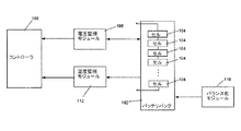
1つ又はそれ以上の実施形態は、バランス化(balancing)モジュールも含む。これらの実施形態の幾つかにおいて、1つ又はそれ以上のリチウムイオンセルは、セル対を備え、バランス化モジュールは、隣接するセル対の相対電圧レベルを評価することができ、隣接セル対の間で電荷を再配分して、対のセル電圧の差を緩和する。 One or more embodiments also include a balancing module. In some of these embodiments, the one or more lithium ion cells comprise a cell pair, and the balancing module can evaluate the relative voltage level of adjacent cell pairs, between adjacent cell pairs. To redistribute the charge to alleviate the difference in cell voltage of the pair.
該システムの幾つかの実施形態は、コントローラも含む。これらの実施形態の幾つかにおいて、コントローラは、1つ又はそれ以上のセルの充電レートを増加及び/又は低下できる。 Some embodiments of the system also include a controller. In some of these embodiments, the controller can increase and / or decrease the charge rate of one or more cells.
該システムの1つ又はそれ以上の実施形態において、1つ又はそれ以上の参照電極により、個々のセルの充電状態をバッテリ管理システムへほぼ瞬時にフィードバックすることが可能になる。これらの幾つかにおいて、バッテリ管理システムは、少なくとも1つのセルの充電プロトコルをほぼリアルタイムで調整可能である。 In one or more embodiments of the system, one or more reference electrodes allow for almost instantaneous feedback of individual cell state of charge to the battery management system. In some of these, the battery management system can adjust the charging protocol of at least one cell in near real time.
該システムの幾つかの実施形態において、システムは充電状態を推測できる。これらの実施形態の幾つかにおいて、システムは、推測した充電状態を目標の充電状態と比較することができ、バッテリ管理システムは、少なくとも1つのセルの充電レートを上向きまたは下向きに調整できる。 In some embodiments of the system, the system can infer the state of charge. In some of these embodiments, the system can compare the estimated charge state to the target charge state, and the battery management system can adjust the charge rate of at least one cell upward or downward.
他の態様は、リチウムイオンバッテリ内のリチウムメッキを回避する方法であり、該方法は、リチウムイオンバッテリの充電中に、参照電極に対する負極の電位を測定すること、測定した電位とリチウム金属のメッキに関連した臨界電位とを比較すること、リチウムイオンバッテリの充電条件を調整して、負極でのリチウムメッキを防止またはリスクを低減することとを含む。この方法の幾つかの実施形態は、充電の終了により充電を調整すること、あるいは充電レートを変更することを含む。 Another aspect is a method of avoiding lithium plating in a lithium ion battery, the method comprising measuring a potential of a negative electrode with respect to a reference electrode during charging of the lithium ion battery, plating the measured potential and lithium metal. Comparison with the critical potential associated with the battery and adjusting the charging conditions of the lithium ion battery to prevent or reduce the risk of lithium plating on the negative electrode. Some embodiments of the method include adjusting charging upon termination of charging or changing the charging rate.
他の態様は、充電の際、いずれか特定のSOCで印加される充電電流を最大化することによって、リチウムイオンバッテリの充電時間を最小化する方法であって、該方法は、バッテリの充電中に、参照電極に対する負極の電位を測定すること(前記充電は、ある充電レートを有する)、バッテリの充電状態を決定すること、測定した充電状態と充電状態プロファイルとを比較すること、充電レートを上向きまたは下向きに調整して、実際の充電レートを、最適安全動作および最適充電レートの1つ又はそれ以上を提供する所定の範囲内に維持して、充電時間を最小化することを含む。 Another aspect is a method of minimizing the charging time of a lithium-ion battery by maximizing the charging current applied at any particular SOC during charging, the method being during battery charging Measuring the potential of the negative electrode with respect to the reference electrode (the charge has a certain charge rate), determining the state of charge of the battery, comparing the measured state of charge with the state of charge profile, Adjusting upward or downward includes maintaining the actual charge rate within a predetermined range that provides one or more of optimal safe operation and optimal charge rate to minimize charge time.
他の態様は、缶とセルの何れかの端子との間の電気接続が存在するか否かを決定する方法であって、該方法は、缶の内側に、何れかの端子とは異なる酸化還元(redox)電位を有する材料を塗布すること(電位差は0.2Vより大きい)、少なくとも1つの端子と缶との間の電圧を測定することを含む。 Another aspect is a method for determining whether there is an electrical connection between a can and any terminal of the cell, the method comprising a different oxidation on the inside of the can than either terminal. Applying a material having a redox potential (potential difference is greater than 0.2V), measuring the voltage between at least one terminal and the can.
他の態様は、電力を供給する方法であって、該方法は、先に開示したリチウムイオンバッテリシステムからなるグループから選択されたリチウムイオンバッテリシステムを実装することを含む。これらの方法の幾つかにおいて、リチウムイオンバッテリは、過充電、過放電、過剰な充電電流、過剰な放電電流を含むグループから選択される1つ又はそれ以上のパラメータを監視する。1つ又はそれ以上の実施形態において、該方法は、隣接するセル対の相対電圧レベルを推測すること、隣接セル対の間で電荷を再配分して、対のセル電圧での差を緩和することを含む。他の実施形態において、該方法は、1つ又はそれ以上のセルの充電レートを増加及び/又は低下させることを含む。さらに他の実施形態において、該方法は、少なくとも1つのセルの充電プロトコルをほぼリアルタイムで調整することを含む。さらに他の実施形態において、該方法は、充電状態を推測することを含む。 Another aspect is a method of supplying power, the method comprising implementing a lithium ion battery system selected from the group consisting of the previously disclosed lithium ion battery systems. In some of these methods, the lithium ion battery monitors one or more parameters selected from the group comprising overcharge, overdischarge, overcharge current, overdischarge current. In one or more embodiments, the method estimates the relative voltage levels of adjacent cell pairs, redistributes charge between adjacent cell pairs, and mitigates differences in paired cell voltages. Including that. In other embodiments, the method includes increasing and / or decreasing the charge rate of one or more cells. In yet another embodiment, the method includes adjusting a charging protocol for at least one cell in near real time. In yet another embodiment, the method includes inferring a state of charge.
本発明およびその利点の大部分のより完全な認識が、本発明の説明を参照して、下記図面と関連して考慮した場合に理解されよう。図面は、説明目的だけで提示したものであって、限定することは意図していない。当業者の届く範囲内にある他の実施形態および変形例は、本発明に含まれることを意図している。 A more complete appreciation of the invention and most of its advantages will be understood when considered in conjunction with the following drawings, with reference to the description of the invention. The drawings are presented for illustrative purposes only and are not intended to be limiting. Other embodiments and variations within the reach of those skilled in the art are intended to be included in the present invention.
三電極セルは、電気化学セルの状態を監視して、セル特性に関する情報を取得する手段を提供する。この情報は、バッテリの充電状態および他の重要なセル特性を決定するために用いられる。こうした情報は、例えば、PHEVにおいて見られるように、厳しい動作パラメータを持つ多重セルを含む複雑なバッテリシステムを監視し最適化するためにますます必要になる。 The three-electrode cell provides a means of monitoring the state of the electrochemical cell and obtaining information regarding cell characteristics. This information is used to determine the state of charge of the battery and other important cell characteristics. Such information is increasingly needed to monitor and optimize complex battery systems including multiple cells with harsh operating parameters, such as found in PHEVs.
三電極セルは、セル性能を監視し最適化するのに有用であるが、こうしたシステムは、ある挑戦をもたらすことになる。例えば、追加電極の使用は、セル設計の複雑さを増加させる。特に、第3の電極およびその端子を収容するために、セル構造の再設計を必要とし、典型的にはセル容器内に追加ポートが必要になる。例えば、EP1577914を参照。追加ポートは、セル設計を不必要に複雑にする。また、ポートは破裂および漏洩の追加箇所であるため、追加の安全リスクをもたらす。 Three electrode cells are useful for monitoring and optimizing cell performance, but such a system presents certain challenges. For example, the use of additional electrodes increases the complexity of cell design. In particular, the cell structure needs to be redesigned to accommodate the third electrode and its terminals, and an additional port is typically required in the cell container. See, for example, EP 1577914. Additional ports complicate cell design unnecessarily. Also, the port introduces additional safety risks because it is an additional point of rupture and leakage.
一態様において、三電極バッテリおよびバッテリシステムには、改善した性能、および第3電極を収容するためにセル缶設計の追加変更を要しない簡素化した設計が提供される。 In one aspect, a three-electrode battery and battery system is provided with improved performance and a simplified design that does not require additional changes to the cell can design to accommodate the third electrode.
動作方法、監視方法およびセル性能の最適化方法も提供される。 A method of operation, a method of monitoring and a method of optimizing cell performance are also provided.
(電気化学セルおよびバッテリ)
1つ又はそれ以上の参照電極を含む電気化学セルについて図1を参照して説明する。電気化学セルは、巻き構造の円柱セルや巻き構造または積層構造の角柱セルなどの任意の幾何形状のものにできる。電気化学セルは、容積が1cm3未満から1リットル超までの範囲で小型または大型のものでもよく、0.1Ah未満から100Ah超までの範囲の電荷容量を有してもよい。
(Electrochemical cells and batteries)
An electrochemical cell including one or more reference electrodes will be described with reference to FIG. The electrochemical cell can be of any geometric shape, such as a cylindrical cell with a wound structure or a prismatic cell with a wound structure or a laminated structure. The electrochemical cell may be small or large with a volume ranging from less than 1 cm 3 to more than 1 liter and may have a charge capacity ranging from less than 0.1 Ah to more than 100 Ah.
1つ又はそれ以上の電気化学セルは、1つ又はそれ以上のバッテリに形成できる。バッテリは、任意の幾何形状のものにできる。例えば、バッテリは、角柱バッテリや円柱バッテリなどにできる。例えば、リチウムイオンバッテリは、典型的にはバッテリパックに包含され、直列及び/又は並列に電気接続された複数の電気化学セルを含む。リチウムイオンバッテリパックは、バッテリパックの意図する用途に依存して、全ての形状、サイズ、エネルギー容量および出力定格がある。バッテリパックは、典型的には、多数のリチウムイオンセルおよびバッテリ管理システムを含むことになる。 One or more electrochemical cells can be formed into one or more batteries. The battery can be of any geometric shape. For example, the battery can be a prismatic battery or a cylindrical battery. For example, a lithium ion battery is typically included in a battery pack and includes a plurality of electrochemical cells electrically connected in series and / or in parallel. Lithium ion battery packs come in all shapes, sizes, energy capacities and power ratings, depending on the intended use of the battery pack. A battery pack will typically include a number of lithium ion cells and a battery management system.
電気化学セルおよびこのバッテリ/バッテリパックの種々のタイプ全てが、本発明の範囲内である。しかしながら、簡素化のため、ここでは簡単な袋状の電気化学セルを参照して説明する。 All of the various types of electrochemical cells and this battery / battery pack are within the scope of the present invention. However, for the sake of simplicity, the description will be given here with reference to a simple bag-like electrochemical cell.
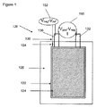
図1に示すように、電気化学セルは、セパレータ126によって電気絶縁された負極122および正極124を含む。負極および正極(122,124)は、外部回路との電気コンタクトのための端子として機能する分離タブ(130,132)を有する。セルは、作動電極(122,124)から電気絶縁された参照電極134と、セルから出て、電気的測定および参照電極の制御のための追加端子を提供する分離タブ136とを含む。ここでより詳しく説明する一定の実施形態において、参照電極用の端子は、セルを収容する導電缶であり、これによりバッテリに追加ポートを持つ必要性を回避している。ある実施形態では、参照電極は、電気化学的に不活性で、電解質によって濡れている多孔性の電気絶縁材料(不図示)、例えば、マイクロ多孔性ポリエチレン、あるいは、バインダを有する絶縁セラミック粒子の混合物、例えば、PVDFや他のポリマーバインダを有するTiO2またはAI2O3、あるいは、バッテリセパレータに広く使用される他の材料に包まれている。
As shown in FIG. 1, the electrochemical cell includes a
(正極)
作動電極は、従来の何れの正極および負極でもよい。例として、リチウムイオンバッテリの正極に適切な材料は、LiCoO2,LiNiO2,LiMnO2,LiMn2O4,LiFePO4,V2O5、あるいは、当業者に広く知られた他のカソード、例えば、バインダおよび必要に応じて導電添加剤、例えばカーボンと混合したLixMO2(Mは、Ni,Co,Mn,Al,Mg,Crまたは他の金属を含む)などである。
(Positive electrode)
The working electrode may be any conventional positive electrode and negative electrode. By way of example, suitable materials for the positive electrode of a lithium ion battery include LiCoO 2 , LiNiO 2 , LiMnO 2 , LiMn 2 O 4 , LiFePO 4 , V 2 O 5 , or other cathodes widely known to those skilled in the art, such as Binders and optionally conductive additives such as Li x MO 2 mixed with carbon (M includes Ni, Co, Mn, Al, Mg, Cr or other metals).
金属リン酸リチウム化合物(例えば、リチウム−遷移金属−リン酸化合物)も電気活性材料として使用でき、これに限定されないが、ポリアニオン化合物、例えば、オリビン(olivine)化合物、NASICON化合物などである。金属リン酸リチウム化合物は、必要に応じて金属、半金属(metalloid)またはハロゲンでドープしてもよい。 Metallic lithium phosphate compounds (eg, lithium-transition metal-phosphate compounds) can also be used as electroactive materials, including but not limited to polyanion compounds such as olivine compounds and NASICON compounds. The metal lithium phosphate compound may be doped with a metal, metalloid or halogen as required.
具体的な例は、ドープしたナノリン酸塩材料、あるいは、オリビン構造化合物LiMPO4(Mは、V,Cr,Mn,Fe,CoおよびNiのうちの1つ又はそれ以上)を含み、化合物は、必要に応じてLi,MまたはOのサイトにドープされる。Liサイトの欠陥は、金属または半金属の添加によって補償できる。Oサイトの欠陥は、ハロゲンの添加によって補償できる。 Specific examples include doped nanophosphate materials or olivine structure compounds LiMPO 4 (M is one or more of V, Cr, Mn, Fe, Co and Ni), If necessary, the Li, M or O site is doped. Li site defects can be compensated by the addition of metal or metalloid. O-site defects can be compensated by the addition of halogen.
適切な正極材料に関する更なる情報は、米国特許第7338734号(発明の名称"CONDUCTIVE LITHIUM STORAGE ELECTRODE"、米国特許公開第2007/0031732号(発明の名称"NANOSCALE ION STORAGE MATERIALS")で見つけられ、これらは参照により全体として組み込まれる。 Further information regarding suitable cathode materials can be found in US Pat. No. 7,338,734 (invention name “CONDUCTIVE LITHIUM STORAGE ELECTRODE”, US Patent Publication No. 2007/0031732 (invention name “NANOSCALE ION STORAGE MATERIALS”)). Are incorporated by reference in their entirety.
例えば、Pb−酸またはニッケル−カドミウムバッテリなどの水成電解質を備えたバッテリ用の適切な正極材料は、二酸化鉛、オキシ水酸化ニッケル、二酸化マンガンを含む。 For example, suitable cathode materials for batteries with an aqueous electrolyte such as Pb-acid or nickel-cadmium batteries include lead dioxide, nickel oxyhydroxide, manganese dioxide.
(負極)
リチウムイオンバッテリの負極に適切な材料は、カーボン、例えば、黒鉛状または非晶質または部分的に無秩序なカーボン、Liと、Sn,Si,Sb,Al,ZnおよぴAgのうちの1つ又はそれ以上を含む金属合金との間で形成される合金または化合物、あるいは当業者に知られた他のアノード材料を含む。
(Negative electrode)
Suitable materials for the negative electrode of a lithium ion battery include carbon, eg, graphitic or amorphous or partially disordered carbon, Li, and one of Sn, Si, Sb, Al, Zn and Ag. Or alloys or compounds formed with or containing metal alloys, or other anode materials known to those skilled in the art.
例えば、Pb−酸またはニッケル−カドミウムバッテリなどの水成電解質を備えたバッテリ用の適切な負極材料は、鉛、水酸化カドミウム、金属−水素化物合金、亜鉛およびカーボンを含む。 For example, suitable negative electrode materials for batteries with an aqueous electrolyte such as Pb-acid or nickel-cadmium batteries include lead, cadmium hydroxide, metal-hydride alloys, zinc and carbon.
(参照電極)
参照電極用の材料選択は、種々の二次バッテリ、例えば、鉛−酸またはPb−Aバッテリ、アルカリマンガンバッテリ、ニッケル−カドミウムまたは「NiCad」バッテリ、ニッケル−金属水素化物または「NiMH」バッテリ、およびリチウムイオンまたは「Li−ion」バッテリなどにおいて変化するであろう。
(Reference electrode)
The material selection for the reference electrode can be various secondary batteries, such as lead-acid or Pb-A batteries, alkaline manganese batteries, nickel-cadmium or “NiCad” batteries, nickel-metal hydride or “NiMH” batteries, and It will vary, such as in a lithium ion or “Li-ion” battery.
ある実施形態において、参照電極は、作動電極、例えば、電気化学セルのクーロン容量を供給するアノードおよびカソードと比べて、小さいクーロン容量を有することができる。クーロン容量は、電極間で交換可能なクーロン量(電流×時間)である。1つ又はそれ以上の実施形態において、参照電極は、作動電極のクーロン容量の約0.001%足らずから、約20%と同程度までのクーロン容量を有する。幾つかの実施形態において、参照電極は、全体容積の小さな区画(section)を占めることができ、セルの容積エネルギー密度が実質的に減少するのを回避している。 In certain embodiments, the reference electrode can have a small coulomb capacity compared to a working electrode, eg, an anode and cathode that supply the coulomb capacity of an electrochemical cell. The coulomb capacity is a coulomb amount (current × time) exchangeable between electrodes. In one or more embodiments, the reference electrode has a Coulomb capacity of less than about 0.001% to about 20% of the Coulomb capacity of the working electrode. In some embodiments, the reference electrode can occupy a small section of the overall volume, avoiding a substantial decrease in the volumetric energy density of the cell.
参照電極材料は、多くの選択肢の1つでもよい。ある実施形態において、参照電極は、セル環境において長期間安定した参照電位を提供する材料を含むことができる。参照電極は、セルの電気化学環境において熱力学的に安定したものにできる。 The reference electrode material may be one of many options. In certain embodiments, the reference electrode can include a material that provides a stable reference potential for a long period of time in a cell environment. The reference electrode can be thermodynamically stable in the cell's electrochemical environment.
例えば、カーボネイト、エステル、エーテル、ラクトンまたは類似の溶媒を含むリチウムイオンバッテリでは、安定した参照電位が、電解質還元に起因した表面反応(例えば、周知の「固体−電解質界面(SEI: solid-electrolyte interface)」)が発生しない充分に高い絶対電位になる。これは、リチウム金属(Li/Li+)に対して約0.8Vより大きい電位、より好ましくは約1.0Vより大きい電位を持つ参照電極を有することによって達成できる。さらに、電位は、約4V vs.Liより低くすると、電解質成分との酸化反応を回避できる。水成電解質を含むバッテリでは、参照電極は、約0V vs.H2/H+より大きく、約1.2V vs.H2/H+より小さい電位に、即ち、水の安定性ウインドウ(これはpHの関数)の範囲内に選択できる。 For example, in lithium ion batteries containing carbonates, esters, ethers, lactones, or similar solvents, a stable reference potential can cause surface reactions due to electrolyte reduction (eg, the well-known “solid-electrolyte interface (SEI) ) ") Is not generated, and the absolute potential is sufficiently high. This can be achieved by having a reference electrode with a potential greater than about 0.8V, more preferably greater than about 1.0V relative to lithium metal (Li / Li + ). In addition, the potential is approximately 4 V vs. When lower than Li, an oxidation reaction with the electrolyte component can be avoided. For batteries containing an aqueous electrolyte, the reference electrode is approximately 0 V vs. Greater than H 2 / H + , about 1.2 V vs. The potential can be selected to be less than H 2 / H + , ie within the stability window of water (which is a function of pH).
他の例では、参照電極が、使用の際に部分的にリチウム化(lithiated)または脱リチウム化(delithiated)されていても、参照電極は、電位が比較的一定である材料を含むことができる。例えば、化学電位がリチウム化(lithiation)の程度に対して一定である参照電極。リチウム化の程度に対してほぼ一定の化学電位を有する材料は、リチウム活性相と共存するもの、例えば、リチウムの挿入または除去の際に二相反応を受ける化合物など、より多くを有する材料を含むことができる。こうした化合物は、ギブスの位相則によって決定されるように、一定の熱力学的に決定される電位を有する。こうした材料は、いろいろな電位で利用可能であり、所望の参照電極を作製できる。 In other examples, even if the reference electrode is partially lithiated or delithiated in use, the reference electrode can comprise a material that has a relatively constant potential. . For example, a reference electrode whose chemical potential is constant with respect to the degree of lithiation. Materials having a substantially constant chemical potential with respect to the degree of lithiation include materials that have more, such as those that coexist with the lithium active phase, such as compounds that undergo a two-phase reaction upon insertion or removal of lithium be able to. Such compounds have a constant thermodynamically determined potential, as determined by Gibbs phase law. Such materials can be used at a variety of potentials to produce the desired reference electrode.
Liイオンバッテリ用の例示(非限定)の参照電極材料は、チタン酸リチウム(LTO)、リン酸遷移金属リチウム、リチウムマンガンスピネル(組成LiMn2O4とLiMnO2の間での〜3Vの電圧平坦域(plateau)において)、および、リチウムと金属、例えば、スズ、アルミニウム、アンチモンなどとの合金を含む。他の実施形態において、リチウム金属を用いてもよい。LixRuO2、LixTiO2を含むルチル型構造化合物、純粋またはドープした組成の化合物LixMPO4,LixMP2O7,LixMPO4F,LixM2(SO4)3およびLixM2(PO4)3(Mは、Ti,V,Cr,Fe,Mn,NiまたはCoのうちの1つ又はそれ以上)を含むアルカリ遷移金属ポリアニオン化合物、ここで他のアルカリ金属は、Liと部分的に置換してもよく、全てが、参照電極に適切な電気活性材料である。参照電極活性材料は、バッテリの作動電極のいずれかに使用するものと同じであっても、あるいは異なるものでもよい。リチウム充電可能バッテリでは、リチウム金属は、使用可能な参照電極材料の1つである。 Exemplary (non-limiting) reference electrode materials for Li-ion batteries include lithium titanate (LTO), lithium transition metal lithium, lithium manganese spinel (˜3V voltage flat between compositions LiMn 2 O 4 and LiMnO 2 And in the alloy of lithium and metals such as tin, aluminum, antimony and the like. In other embodiments, lithium metal may be used. Li x RuO 2 , rutile structure compounds including Li x TiO 2 , pure or doped compounds Li x MPO 4 , Li x MP 2 O 7 , Li x MPO 4 F, Li x M 2 (SO 4 ) 3 And an alkali transition metal polyanion compound comprising Li x M 2 (PO 4 ) 3, wherein M is one or more of Ti, V, Cr, Fe, Mn, Ni or Co, wherein the other alkali metal May be partially substituted with Li, all of which are electroactive materials suitable for the reference electrode. The reference electrode active material may be the same as or different from that used for any of the battery working electrodes. In lithium rechargeable batteries, lithium metal is one of the reference electrode materials that can be used.
1つ又はそれ以上の実施形態において、安定した一定の電位を供給する多相リチウム活性材料は、参照電極として使用できる。チタン酸リチウム(LTO)は、例示の参照電極材料であり、これに限定されないが、組成Li4+xTi5O12で、スピネル構造を有する化合物などを含む。リチウム挿入の際、この組成は二相反応を受けて、室温、一定の1.55V vs.Li/Li+の電位を供給でき、これはSEI形成を回避するために充分に高い。この化合物は、酸化状態で準備できる。代替として、Li含有量を増加させ、還元性雰囲気、またはLi,TiおよびOの相対量が制約された閉じた系の焼成において焼成することによって二相材料を準備してもよい。酸化した形態を用いた場合、参照電極をリチウムイオンセルに組み込むと、LTOは、一定電位の二相材料ではなくなるであろう。しかしながら、ある実施形態において、参照電極は、リチウムの挿入によって電気化学的にリチウム化でき、参照電極として使用する前に一定電位の二相状態を形成する。 In one or more embodiments, a multiphase lithium active material that provides a stable and constant potential can be used as a reference electrode. Lithium titanate (LTO) is an exemplary reference electrode material and includes, but is not limited to, a compound having a composition of Li 4 + x Ti 5 O 12 and a spinel structure. Upon lithium insertion, this composition undergoes a two-phase reaction and is constant at 1.55 V vs. room temperature. A potential of Li / Li + can be supplied, which is high enough to avoid SEI formation. This compound can be prepared in the oxidized state. Alternatively, the biphasic material may be prepared by firing in a reducing atmosphere or in a closed system firing where the relative amounts of Li, Ti and O are constrained, with increased Li content. If the oxidized form is used, LTO will not be a constant potential two-phase material when the reference electrode is incorporated into a lithium ion cell. However, in certain embodiments, the reference electrode can be lithiated electrochemically by insertion of lithium, forming a constant potential two-phase state prior to use as a reference electrode.
他の例示の参照電極材料は、リン酸塩材料、例えば、ドープしたナノリン酸塩材料、あるいは、オリビン構造LiMPO4(Mは、Fe,Mn,CoおよびNiのうちの1つ又はそれ以上を含む)を含んでもよい。上記のリン酸塩は、リチウム化でき、一定電位の二相状態を形成する。こうした実施形態において、参照電極は、参照電極の大きなサイクルを回避するように動作可能であり、参照電極の化学量論をその二相領域内に維持し、幾つかの相変化材料で固有のヒステリシスに起因した参照電極の電位変化の誘発を回避できる。出発原料として二相リン酸塩が準備でき、あるいは、出発参照電極を電気化学的にリチウム化または脱リチウム化して、二相材料を形成できる。非限定の例として、約3.45V vs.Li/Li+の電位を持つ二相LiFePO4−FePO4混合物が、全体組成Li1−xFePO4(xは、約0.05より大きい)で出発し、熱処理して2つの共存する相を作成することによって準備できる。代替として、参照電極は、集合後、その場(in-situ)で脱リチウム化して二相混合物を作成するようにしたLiFePO4とすることができる。さらに他の例では、参照電極は、集合後、その場(in-situ)でリチウム化して、組成LiyFePO4(yは約0.05より大きい)にするようにしたFePO4とすることができる。 Other exemplary reference electrode materials include phosphate materials, such as doped nanophosphate materials, or olivine-structured LiMPO 4 (M is one or more of Fe, Mn, Co and Ni). ) May be included. The above phosphates can be lithiated and form a constant potential two-phase state. In such embodiments, the reference electrode is operable to avoid large cycles of the reference electrode, maintaining the reference electrode's stoichiometry within its two-phase region, and inherent hysteresis in some phase change materials. Induction of the potential change of the reference electrode due to the can be avoided. A biphasic phosphate can be prepared as a starting material, or the starting reference electrode can be electrochemically lithiated or delithiated to form a biphasic material. As a non-limiting example, about 3.45 V vs. A two-phase LiFePO 4 -FePO 4 mixture with a potential of Li / Li + starts with an overall composition Li 1-x FePO 4 (x is greater than about 0.05) and heat - treats to create two coexisting phases You can prepare by doing. Alternatively, the reference electrode can be LiFePO 4 that is delithiated in-situ after assembly to create a two-phase mixture. In yet another embodiment, the reference electrode, after collection, the in situ (in-situ) by lithiation with, and FePO 4 which is adapted to the composition Li y FePO 4 (y is greater than about 0.05) Can do.
電圧測定では、拡張した電圧測定に渡って幾つかの少量の電流の通過を必要とするため、参照電極の化学量論は、参照電極の容量全てが消費されるポイントまで変化することがあり、その後、参照電極の電位が変化することになる。 Since voltage measurements require the passage of some small amount of current over an extended voltage measurement, the reference electrode stoichiometry can vary to the point where all of the reference electrode capacity is consumed, Thereafter, the potential of the reference electrode changes.
長期間動作のためのシステム設計では、参照電極の消耗を回避するように、電圧測定を運用する。参照電極の化学量論が実質的に変化するのを回避する運用モードの例は、電圧を測定する際の時間を減少させること、電圧測定中に流れる電流の方向を交替させること(即ち、リードの極性を切り換える)、及び/又は、参照電極と作動電極の一方との間に補償電流を周期的に流すことを含む。 In system design for long-term operation, voltage measurement is operated to avoid depletion of the reference electrode. Examples of modes of operation that avoid substantially changing the stoichiometry of the reference electrode are to reduce the time to measure the voltage and to change the direction of the current flowing during the voltage measurement (ie, lead And / or periodically flowing a compensation current between the reference electrode and one of the working electrodes.
参照電極用の活性材料は、金属電流コレクタの上に直接堆積できる。あるいは、活性材料の粒子をバインダと混合可能であり、カーボンなどの導電性添加剤を混合物に添加してもよく、金属箔の上にコートしてもよい。金属箔は、銅、アルミニウム、ニッケル、ステンレス鋼、チタンまたは、参照電極の動作電位ウインドウの下で合金化したり腐食したりしない他の金属でもよい。 The active material for the reference electrode can be deposited directly on the metal current collector. Alternatively, particles of the active material can be mixed with the binder, and a conductive additive such as carbon may be added to the mixture or coated onto the metal foil. The metal foil may be copper, aluminum, nickel, stainless steel, titanium, or other metal that does not alloy or corrode under the operating potential window of the reference electrode.
参照電極の機能は、セル内の特定の場所において安定した電位測定を提供することであるため、その電位に影響を及ぼす要因を最小化することが重要である。例えば、活性参照材料を参照端子と接続する金属リードは、活性参照材料の周辺領域を除いた全ての領域において、電解質とのイオンコンタクトから絶縁すべきである。さらに、参照電極は、電位に関心のある場所に可能な限り接近して配置すべきであり、関心のある場所と参照電極との間には連続したイオン経路が存在するべきである。例えば、目標がリチウムメッキを検出することであれば、参照電極は、負極タブ、詳細には、負極タブに隣接した、セパレータ−負極活性材料界面に可能な限り接近して配置すべきである。 Since the function of the reference electrode is to provide a stable potential measurement at a specific location within the cell, it is important to minimize the factors that affect that potential. For example, the metal lead connecting the active reference material to the reference terminal should be isolated from ionic contact with the electrolyte in all regions except the peripheral region of the active reference material. Furthermore, the reference electrode should be placed as close as possible to the location of interest to the potential, and there should be a continuous ion path between the location of interest and the reference electrode. For example, if the goal is to detect lithium plating, the reference electrode should be placed as close as possible to the negative electrode tab, specifically the separator-negative electrode active material interface adjacent to the negative electrode tab.
1つ又はそれ以上の実施形態において、参照電極は、それ自体の端子を有し、電圧計と接続される。1つ又はそれ以上の実施形態において、参照電極活性材料を参照電極と接続する参照電極リードは、セル壁または、セル缶の上側キャップまたは下側キャップの一方を通るフィードスルー(貫通接続(feedthrough))またはポートを通過する。セルを通るフィードスルーは、密閉する必要がある。こうしたシールは、ガスケット、ガラス−金属シール、ラミネーションまたは他の公知技術によって、密閉にできる。 In one or more embodiments, the reference electrode has its own terminal and is connected to a voltmeter. In one or more embodiments, the reference electrode lead connecting the reference electrode active material to the reference electrode is a feedthrough that passes through either the cell wall or one of the upper or lower caps of the cell can. ) Or pass through the port. The feedthrough through the cell must be sealed. Such seals can be sealed by gaskets, glass-metal seals, lamination or other known techniques.
1つ又はそれ以上の実施形態において、参照電極は、セル壁または上側キャップまたは下側キャップの1つと一体化しており、追加ポートまたはフィードスルーを必要としない。1つ又はそれ以上の参照電極端子を備えたバッテリでは、セル壁またはエンドキャップへの参照電極端子の一体化は、フィードスルーまたはポートを経由した参照端子を収容するバッテリに対して幾つかの著しい利点を提供する。参照端子用のフィードスルーのセル設計は、複雑になり、費用がかかり、耐久性が低くなることがある。参照端子用のフィードスルーに必要な密閉シールは、電位漏れ経路をシステムに追加する。こうした密閉シールの不良は、電解質を漏らすバッテリとなって、バッテリ全体の故障を引き起こすであろう。こうした参照端子フィードスルーに必要な構造は、バッテリ内で追加のスペースを必要とする。さらに、こうした参照端子フィードスルーは、余分の重量をバッテリに追加する。 In one or more embodiments, the reference electrode is integral with the cell wall or one of the upper or lower cap and does not require an additional port or feedthrough. In batteries with one or more reference electrode terminals, the integration of the reference electrode terminal into the cell wall or end cap is several significant for batteries that house the reference terminal via a feedthrough or port. Provides benefits. The feedthrough cell design for the reference terminal can be complex, expensive, and less durable. The hermetic seal required for the feedthrough for the reference terminal adds a potential leakage path to the system. Such a poor seal would result in a battery that leaks electrolyte, causing failure of the entire battery. The structure required for such reference terminal feedthrough requires additional space within the battery. In addition, these reference terminal feedthroughs add extra weight to the battery.
セル壁またはエンドキャップへの参照電極端子の一体化は、追加のフィードスルーを不要にする。その結果、新しい電位漏れ経路が生成されず、追加のフィードスルーを収容するのに要するスペースが節約され、追加のフィードスルーの重量も節減される。セル壁またはエンドキャップに一体化した参照電極端子を備えたバッテリの1つの結果は、バッテリがより軽量に、より小型になり、そして、追加の電位漏れ経路が無いため、より耐久性のあるものになる。 Integration of the reference electrode terminal into the cell wall or end cap eliminates the need for additional feedthrough. As a result, no new potential leakage path is created, the space required to accommodate the additional feedthrough is saved, and the weight of the additional feedthrough is also saved. One result of a battery with a reference electrode terminal integrated into the cell wall or end cap is that the battery is lighter, smaller, and more durable because there is no additional potential leakage path become.
セル壁またはエンドキャップに一体化した参照電極端子を有する実施形態の他の利点は、電圧を測定するのに必要な構造の追加のフレキシビリティーである。これらの実施形態の参照端子は缶に電気接続されており、缶およびエンドキャップは導電性であるため、実際、缶またはエンドキャップでの何れのポイントも参照電極の電位を測定するために使用可能である。この特徴は、セル設計において著しいフレキシビリティーを提供する。実際、缶またはエンドキャップの表面のどこででも参照電極での電位が測定可能であるからである。 Another advantage of embodiments having a reference electrode terminal integrated into the cell wall or end cap is the additional flexibility of the structure required to measure the voltage. Since the reference terminal in these embodiments is electrically connected to the can and the can and end cap are conductive, in fact any point on the can or end cap can be used to measure the potential of the reference electrode. It is. This feature provides significant flexibility in cell design. In fact, the potential at the reference electrode can be measured anywhere on the surface of the can or end cap.
ある実施形態は、缶と一体化した1つ又はそれ以上の参照電極を有する。参照電極が缶と電気接続されている実施形態において、缶全体が有効に参照端子になることができる。缶が有効に参照端子となる場合、缶はエンドキャップから電気絶縁して、電極を異なる電位に維持する必要がある。ガスケットは、セルエンドキャップと缶830との間の電気絶縁を提供する。適切なガスケットに関する更なる情報は、係属中の米国特許出願番号第11/515597号(発明の名称"BATTERY CELL DESIGN AND METHOD OF ITS CONSTRUCTION")で見つけられ、これは参照により全体として組み込まれる。
Some embodiments have one or more reference electrodes integrated with the can. In embodiments where the reference electrode is electrically connected to the can, the entire can can effectively be the reference terminal. If the can effectively serves as a reference terminal, the can must be electrically isolated from the end cap to maintain the electrodes at different potentials. The gasket provides electrical insulation between the cell end cap and the
図13は、正端子及び/又は負端子を缶から電気絶縁するために、本発明の1つ又はそれ以上の実施形態に従って使用可能なガスケットを含むエンドキャップの図である。図13A〜図13Cは、中心に位置する充填孔(40)を含む負側エンドキャップ(5)を示す。いったん組み立てられ、電力端子を構成する中空の孔リベット(45)によって少なくとも部分的に形状が定まると、充填孔はセルを活性化するために使用される。 FIG. 13 is an illustration of an end cap that includes a gasket that can be used in accordance with one or more embodiments of the present invention to electrically insulate the positive and / or negative terminals from the can. 13A-13C show a negative end cap (5) that includes a centrally located filling hole (40). Once assembled and filled at least in part by the hollow hole rivet (45) that constitutes the power terminal, the fill hole is used to activate the cell.
充填孔および電力端子の両方として、負側エンドキャップの中心位置の共用は、スペースの効率的な使用を提供し、バッテリ動作を妨害しない。充填孔(40)は、エンドキャップ面の中心に配置される。中心に配置された充填孔は、孔内に嵌め合いで配置され、セルの内部と連結するフィードスルー注入口(inlet)を提供する。電解質は、活性化の際、このフィードスルー注入口を通じて導入される。 Sharing both the center position of the negative end cap as both a fill hole and a power terminal provides efficient use of space and does not interfere with battery operation. The filling hole (40) is arranged at the center of the end cap surface. A centrally located fill hole is fitted in the hole and provides a feedthrough inlet that connects with the interior of the cell. The electrolyte is introduced through this feedthrough inlet upon activation.
負側エンドキャップは、図13Aの分解図に示すように、構成部品を組み立てることによって構築される。上側ガスケット(44)は、エンドキャップ本体(43)の中に置かれ、これはガスケットを受け入れるための凹みを有してもよい。電力端子(45)として機能する中空の孔リベットは、上側ガスケット(44)の中に組み込まれる。リベット(45)のステム(45a)は、上側ガスケット(44)およびエンドキャップ本体(43)の両方の中心開口を通って延びている。このアセンブリを裏返して、シールガスケット(47)をガスケット(44)の上に挿入し、本体(43)の上に置く。図4Aに示すように、下側ガスケット(42)、シールガスケット(47)およびリベット裏当て円板(46)が組み立てられ、位置決めされる。延長タブ(41)がリベット(45)のステムに挿入される。圧着前の組み立て状態の構成部品を図13Bに示す。 The negative end cap is constructed by assembling the components as shown in the exploded view of FIG. 13A. The upper gasket (44) is placed in the end cap body (43), which may have a recess for receiving the gasket. A hollow hole rivet functioning as a power terminal (45) is incorporated into the upper gasket (44). The stem (45a) of the rivet (45) extends through the central opening of both the upper gasket (44) and the end cap body (43). The assembly is turned over and a sealing gasket (47) is inserted over the gasket (44) and placed over the body (43). As shown in FIG. 4A, the lower gasket (42), the seal gasket (47), and the rivet backing disc (46) are assembled and positioned. The extension tab (41) is inserted into the stem of the rivet (45). The components in the assembled state before crimping are shown in FIG. 13B.
リベット(45)は、良好な耐食性および良好な溶接性のためにNiメッキ鋼でもよく、セル用の電力端子として機能する。リベット(45)の平坦ヘッドは、エンドキャップの外側面のある位置に延びており、中空ステム(45a)はセルの内側に延びている。それは、封止に役立つように加工した出っ張り(ledge)を備えた、その中心を通る充填孔と、対称的な形状と、バッテリ端子と充填孔との間のスペースと対称性を共有する中心配置のリベットステムとを含む。延長タブ(41)は、電力端子(45)をセルの内部活性アノード材料と接続する。下側ガスケット(42)は、延長タブ(41)を、異なる電位にあるエンドキャップ本体(43)との接触から保護する。本体(43)は、これに限定されないが、圧着および溶接の上記方法などの多くの方法によって、バッテリチューブ(不図示)またはセルのメイン本体に対して密閉封止される。上側ガスケット(44)は、電力端子(45)を、異なる電位にあるエンドキャップ本体(43)から絶縁している。リベット裏当て円板(46)は、強い押圧リベット取り付け力を本体(43)に作用させるのに役立つ。シールガスケット(47)は、押圧リベットの下で頑丈な封止を達成するのに役立つ。 The rivet (45) may be Ni plated steel for good corrosion resistance and good weldability and functions as a power terminal for the cell. The flat head of the rivet (45) extends to a position on the outer surface of the end cap, and the hollow stem (45a) extends to the inside of the cell. It has a ledge that is machined to aid sealing, a filling hole through its center, a symmetrical shape, and a central arrangement that shares the space and symmetry between the battery terminal and the filling hole And rivet stem. The extension tab (41) connects the power terminal (45) with the cell's internal active anode material. The lower gasket (42) protects the extension tab (41) from contact with the end cap body (43) at different potentials. The body (43) is hermetically sealed to the battery tube (not shown) or the main body of the cell by many methods including, but not limited to, the methods described above for crimping and welding. The upper gasket (44) insulates the power terminal (45) from the end cap body (43) at different potentials. The rivet backing disc (46) helps to exert a strong pressing rivet attachment force on the body (43). The sealing gasket (47) helps to achieve a robust seal under the pressing rivet.
アセンブリ全体は、図13Cに示すように、リベット(45)のステムを押圧して変形させることによって一緒に圧着してもよく、部品の全てを一緒に締め付けて押圧リベット(48)を形成し、延長タブ(41)と電力端子(45)との間の良好な電気コンタクトを生成する。 The entire assembly may be crimped together by pressing and deforming the stem of the rivet (45), as shown in FIG. 13C, and clamping all of the parts together to form a pressing rivet (48), Produces good electrical contact between the extension tab (41) and the power terminal (45).
同じテクニックがセルの正端子を作成するために応用できる。しかしながら、セルの正端子では、リベット(45)、延長タブ(41)およびリベット裏当て円板(46)は、好ましくは、アルミニウム、アルミニウム合金または、正側セル電位で耐食性のある材料で構成される。こうした材料は、ステンレス鋼、モリブデン、ハステロイ(hastelloy)、または他の知られた耐食性合金を含んでもよい。 The same technique can be applied to create the positive terminal of the cell. However, at the positive terminal of the cell, the rivet (45), extension tab (41) and rivet backing disc (46) are preferably constructed of aluminum, an aluminum alloy or a material that is corrosion resistant at the positive cell potential. The Such materials may include stainless steel, molybdenum, hastelloy, or other known corrosion resistant alloys.
当業者に容易に明らかなように、他の方法およびガスケットを採用してもよい。 Other methods and gaskets may be employed as will be readily apparent to those skilled in the art.
参照端子を缶と一体化する幾つかの実施形態において、缶から作動電極を電気絶縁するためのガスケット付きエンドキャップの追加は、一体化した参照端子に起因する節約を骨抜きにしない。ガスケット付きエンドキャップの重量、スペース要求、漏れ電位は、全て参照電極端子を収容する追加フィードスルーのものより小さく、これらの実施形態において一体化した参照端子の利益を保持できる。 In some embodiments in which the reference terminal is integrated with the can, the addition of a gasketed end cap to electrically isolate the working electrode from the can does not eliminate the savings due to the integrated reference terminal. The weight, space requirements, and leakage potential of the gasketed end cap are all less than that of the additional feedthrough that houses the reference electrode terminal, and can retain the benefits of the integrated reference terminal in these embodiments.
参照電極をバッテリに追加する場合の他の懸念は、参照電極は、作動セルから絶縁する必要がある点である。これは、典型的には、絶縁材料を、参照電極の周りまたは参照電極と作動電極との間に配置し、バッテリ内の構成部品を絶縁することを必要とする。缶壁またはエンドキャップの少なくとも一部にコートされた参照電極用の活性材料を有することによって、参照端子を缶またはエンドキャップと一体化した実施形態において、参照電極の活性材料を絶縁するプロセスは簡略化される。コートされた活性材料は、絶縁によって覆われている必要があるためである。 Another concern when adding a reference electrode to the battery is that the reference electrode needs to be isolated from the working cell. This typically requires that an insulating material be placed around the reference electrode or between the reference electrode and the working electrode to insulate components within the battery. In embodiments in which the reference terminal is integrated with the can or end cap by having the reference electrode active material coated on at least a portion of the can wall or end cap, the process of insulating the reference electrode active material is simplified. It becomes. This is because the coated active material needs to be covered by insulation.
参照端子を缶またはエンドキャップと一体化した実施形態における他の利点は、参照電極とバッテリ電解質との間のコンタクトを維持することである。これは、電解質は、缶およびエンドキャップの内側と流体接触しているためであり、ある実施形態において参照電極と接触することになる。 Another advantage in embodiments where the reference terminal is integrated with the can or end cap is to maintain contact between the reference electrode and the battery electrolyte. This is because the electrolyte is in fluid contact with the inside of the can and end cap, and in some embodiments will be in contact with the reference electrode.
さらに他の実施形態において、缶自体が疑似参照電極として機能してもよく、セル設計をさらに簡略化する。缶がアルミニウム、銅、ステンレス鋼またはチタンなどの金属である場合、缶は、参照電極として機能することが可能である。缶の内壁表面は、作動電極から缶の電気絶縁を提供するように、保護絶縁材料でコート可能である。缶の内壁をコートするのに使用できる例示の保護絶縁材料は、ポリイソブチレン、ポリオレフィン、エポキシなどのポリマー、またはアルミナ、ジルコニアなどのセラミックを含む。適切な接続は、缶の外壁に沿った何れのポイントでも可能であり、参照電極−負極の電位を測定できる回路を生成する。 In yet other embodiments, the can itself may function as a pseudo reference electrode, further simplifying the cell design. If the can is a metal such as aluminum, copper, stainless steel or titanium, the can can function as a reference electrode. The inner wall surface of the can can be coated with a protective insulating material to provide electrical insulation of the can from the working electrode. Exemplary protective insulating materials that can be used to coat the inner wall of the can include polymers such as polyisobutylene, polyolefins, epoxies, or ceramics such as alumina, zirconia. Appropriate connections are possible at any point along the outer wall of the can, creating a circuit that can measure the reference electrode-negative electrode potential.
(参照電極の利点)
特定の参照電極の組み込みは、電気化学セルに対してある範囲の監視能力を提供する。参照電極によって得られる情報は、バッテリ監視システムに提供できる。電極電位の正確な測定は、セルの充電状態の正確な決定を可能にする。充電状態は、何れかの作動電極と参照電極との間の電位差に直接に相関があるためである。さらに、インピーダンスがSOCに依存するシステムでは、電極電位の正確な測定は、電極インピーダンスに関する情報も提供する。バッテリ監視システムは、これと他の情報、例えば、セル電圧、電流、温度などを使用して、個々の電気化学セルおよび全体のバッテリシステムの種々の機能を制御できる。従って、バッテリ管理システムは、充電状態を正確に監視し、この情報に基づいてバッテリの健康状態の管理を行うように発展可能である。1つ又はそれ以上の実施形態において、バッテリ管理システムは、負極電位を監視し、高レートの充電時にLi堆積を防止するように設けられる。他の実施形態において、バッテリ監視システムは、何れかの特定のSOCで印加される充電電流を最大化することによって、充電時間を最小化するように設けられる。
(Advantages of reference electrode)
The incorporation of a specific reference electrode provides a range of monitoring capabilities for the electrochemical cell. Information obtained by the reference electrode can be provided to the battery monitoring system. Accurate measurement of the electrode potential allows an accurate determination of the state of charge of the cell. This is because the state of charge is directly correlated to the potential difference between any working electrode and the reference electrode. Furthermore, in systems where the impedance depends on SOC, accurate measurement of electrode potential also provides information regarding electrode impedance. The battery monitoring system can use this and other information, such as cell voltage, current, temperature, etc., to control various functions of individual electrochemical cells and the overall battery system. Thus, the battery management system can be developed to accurately monitor the state of charge and manage the health of the battery based on this information. In one or more embodiments, a battery management system is provided to monitor negative potential and prevent Li deposition during high rate charging. In other embodiments, a battery monitoring system is provided to minimize charging time by maximizing the charging current applied at any particular SOC.
(1.充電状態の決定)
充電状態(SOC)は、容量の百分率として定義され、バッテリは、バッテリが平衡状態で完全に放電された電圧下限と、バッテリが平衡状態で完全に充電された電圧上限との間を示す。こうして0% SOCは、完全放電状態に対応し、100% SOCは、完全充電状態に対応する。健康状態(SOH)は、電力およびエネルギーを配給するバッテリの現在の能力の指標であり、典型的には、セルインピーダンスおよび容量の変化に関連した情報を含む。
(1. Determination of state of charge)
The state of charge (SOC) is defined as the percentage of capacity, and the battery represents between the lower voltage limit at which the battery is fully discharged in equilibrium and the upper voltage limit at which the battery is fully charged in equilibrium. Thus, 0% SOC corresponds to a fully discharged state, and 100% SOC corresponds to a fully charged state. Health status (SOH) is an indicator of the current ability of a battery to deliver power and energy, and typically includes information related to changes in cell impedance and capacity.
2つの端子130,132の間に回路150または電気接続を生成することによって、ある電圧を正極と負極に印加できる。電圧は、正極の電位と負極の電位との間の差である。差は得られるが、単一電極の絶対値は測定できない。一般に、電極の一方または両方がSOCとともに電位の変化を示す場合、セル電圧は、電気化学セルのSOCを決定するのに適している。実際、SOCは、従来からこの方法で決定していいる。しかしながら、セル電圧は、セルの充電状態について貧弱な指標であるという状況がある。例えば、両方の電極が充電状態とともに電位変動を示し、セルは、一方または両方の電極の化学量論を時間とともに変化させる分解反応を受ける場合、セル電圧はもはや、電極の充電状態について信頼性のある指標ではない。一方または両方の作動電極における固有のヒステリシスは、セル電圧と充電状態との間の関係に不確実さをもたらすことがある。最後に、電流の通過によって誘導される分極は、セル電圧を変化させる。参照電極により、どの程度の分極が一方または他方の電極に帰属しているかを識別するのを可能にする。
A voltage can be applied to the positive and negative electrodes by creating a
一方または両方の作動電極における固有のヒステリシスは、SOCを監視するために電圧を用いるという問題を生じさせ得る。これは、高いヒステリシスを持つ材料において、所定電圧でのSOCが充電及び/又は放電の履歴の関数となることがあるからである。参照電極の使用により、固有のヒステリシスを持つシステムは、参照電極に対して正極及び/又は負極の電位を別々に監視することによって、SOCをより正確に監視できる。これは、負極−参照電極または正極−参照電極の電位では全体のセル電圧よりもヒステリシスが少ないためであり、これは負極および正極の両方からヒステリシスへの関与を含んでいる。 The inherent hysteresis in one or both working electrodes can cause the problem of using voltage to monitor the SOC. This is because in a material with high hysteresis, the SOC at a given voltage may be a function of the charge and / or discharge history. Through the use of a reference electrode, systems with inherent hysteresis can more accurately monitor the SOC by separately monitoring the positive and / or negative potentials with respect to the reference electrode. This is because there is less hysteresis at the negative electrode-reference electrode or positive electrode-reference electrode potential than the overall cell voltage, and this involves the participation of hysteresis from both the negative electrode and the positive electrode.
従って、ある実施形態では、正極及び/又は負極の電位は、参照電極を用いて決定または制御できる。ある実施形態では、参照電極においてその化学量論の関数としての電位変動が、負極または正極での電位変動よりはるかに安定しているように、参照電極を選択できる。幾つかの他の実施形態において、一方または両方の作動電極におけるSOCの関数としての電位変動は、参照電極における電位変動よりはるかに安定している。 Thus, in certain embodiments, the potential of the positive electrode and / or the negative electrode can be determined or controlled using the reference electrode. In some embodiments, the reference electrode can be selected such that the potential variation as a function of its stoichiometry at the reference electrode is much more stable than the potential variation at the negative or positive electrode. In some other embodiments, the potential variation as a function of SOC at one or both working electrodes is much more stable than the potential variation at the reference electrode.
例えば、回路152を参照電極134と負極122の間に作成してもよく、参照電極は、負極よりも、その化学量論の関数としての電位変動がはるかに安定している。参照電極は、その安定性で選択されるため、電位の測定および変化が負極での状態を示すことができ、SOCは、この差を測定することによって決定できる。
For example, a
他の非限定の例として、回路を参照電極134と正極124の間に作成してもよく、参照電極は、正極よりも、SOCの関数としての電位変動がはるかに安定している。参照電極は、その安定性で選択されるため、電位の測定および変化が正極での状態を示すことができ、SOCは、この差を測定することによって決定できる。
As another non-limiting example, a circuit may be created between the reference electrode 134 and the
ある実施形態において、参照電極は、セル内部に、電位が最大で変化する場所、あるいは、望ましくない電位逸脱の結果が最も重大であるような場所に配置できる。例えば、電位、分極および温度が場所によって変化するような大型セルでは、参照電極は、こうした変動が最も極端である場所に配置してもよい。例えば、参照電極は、急速充電時にリチウムメッキが発生することがある、負極の活性エリアのすぐ外側に配置できる。 In certain embodiments, the reference electrode can be placed inside the cell where the potential changes at a maximum or where the consequences of unwanted potential excursions are most significant. For example, in a large cell where the potential, polarization, and temperature vary from place to place, the reference electrode may be placed where these variations are most extreme. For example, the reference electrode can be placed just outside the active area of the negative electrode where lithium plating can occur during rapid charging.
幾つかの他の実施形態において、1つ又はそれ以上の参照電極は、電解質内での電気化学電位の空間変動を監視するために、単一セル内部のいろいろな場所に分布することができる。各参照電極は、独立した端子を有することになるであろう。 In some other embodiments, one or more reference electrodes can be distributed at various locations within a single cell to monitor spatial variations in electrochemical potential within the electrolyte. Each reference electrode will have an independent terminal.
(2.バッテリ管理システム)
上述のように、バッテリパックは、多数の電気化学セルと、バッテリ管理システムとを含むことができる。バッテリ管理システムは、温度、電流および電圧を監視するためのセンサと、安全なレベルの電圧および電流を維持する電圧コンバータおよびレギュレータ回路と、電力および情報をバッテリパックから出し入れする電気コネクタと、バッテリの現在の充電状態を推測するバッテリ充電状態モニタとを含むことができる。バッテリモニタは、バッテリパラメータに関連したデータを蓄積して、これをホストコンピュータへ送信することができる。バッテリモニタは、例えば、バッテリデータを保持するための1つ又はそれ以上のタイプのデジタルメモリおよび特殊なレジスタなど、アナログ回路およびデジタル回路の両方を組み込んだ混合信号集積回路を含むことができる。
(2. Battery management system)
As described above, a battery pack can include a number of electrochemical cells and a battery management system. The battery management system includes sensors to monitor temperature, current and voltage, voltage converter and regulator circuits that maintain safe levels of voltage and current, electrical connectors to and from the battery pack and power and information, And a battery charge state monitor that estimates the current charge state. The battery monitor can accumulate data related to the battery parameters and send it to the host computer. A battery monitor can include a mixed signal integrated circuit that incorporates both analog and digital circuitry, such as, for example, one or more types of digital memory and special registers for holding battery data.
バッテリ管理システムによって監視可能な幾つかの例示のパラメータは、過充電(過電圧)、過放電(電圧不足)、過剰な充電電流および放電電流(過電流、短絡)、Liイオンバッテリシステムにおける特に重要な情報を含む。ある実施形態において、バッテリモニタは、有害な過充電および電流条件からバッテリを保護することによって、保護回路の幾つかの機能を持つことがてきる。 Some exemplary parameters that can be monitored by the battery management system are overcharge (overvoltage), overdischarge (undervoltage), excessive charge and discharge currents (overcurrent, short circuit), particularly important in Li-ion battery systems. Contains information. In certain embodiments, the battery monitor may have several functions of a protection circuit by protecting the battery from harmful overcharge and current conditions.
図2は、バッテリシステムによって提供される一般的な機能性と、バッテリパックを監視し、バランスさせる方法を示す例示のブロック図である。バッテリパック102は、直列及び/又は並列で電気接続された、1つ又はそれ以上のエネルギー配給素子104(例えば、リチウムセル)を含むことができる。
FIG. 2 is an exemplary block diagram illustrating the general functionality provided by the battery system and how to monitor and balance the battery pack. The
電圧監視モジュール106は、各エネルギー配給素子104と関連した電圧情報、状態を受け取って、電圧情報を分離し、電圧情報を、出力ポートを介してシステムコントローラ108に提供する。システムコントローラ108は、充電および放電時に各エネルギー配給素子104を評価して、何れか個々のエネルギー配給素子104に損傷状態の可能性があるか否かを決定する。例えば、充電の際、全体パック電圧が安全レベルを下回っている場合でも、個々のセルが安全電圧レベルに到達または超過しているかもしれない。同様に、放電の際、全体パック電圧が、その最小安全閾値を超えている場合でも、個々のセルが最小安全閾値より降下しているかもしれない。このような場合、システムコントローラ108が、個々のセル電圧が望ましくない値にあることを検出すると、システムコントローラ108は、バッテリパック102(または個々のセル)の充電または放電を中止することができる。
The
バランス化モジュール110は、隣接セル対の相対電圧レベルを評価でき、隣接セル間の電荷を再配分して、対のセル電圧での差を緩和することができる。より詳細に後述するように、バランス化モジュール110は、セル対の他方が除去されたり切断した場合、一方のセルの過剰なセル放電を防止するための機能性を含むことができる。
The
温度監視モジュール112は、バッテリパック102の温度に対応した情報を受け取る。温度情報は、バッテリパック内に配置された熱電対によって出力される電気信号の形態とすることができるが、温度情報は公知の他の形態をとってもよい。温度監視モジュール112は、温度情報をシステムコントローラ108へ提供する。温度監視モジュールは、他のバッテリパック(不図示)からの温度情報を受け取ってもよく、複数のバッテリパックからの温度情報をシステムコントローラ108へ提供する。本説明は、例示の目的だけであり、本発明を限定することは意図していない。
The
(3.バッテリ充電監視)
図3は、充電の際にバッテリ(単一セルまたはバッテリパック)を監視するときの参照電極の使用を示す。バッテリを充電する際、正極は脱リチウム化され、負アノードはリチウム化され、所望の充電状態をセルに提供する。上述のように、所望の充電状態は、完全充電状態(100%)であったり、ある中間値(HEVの場合、40〜60%)であったり、バッテリ用途に依存する。
(3. Battery charge monitoring)
FIG. 3 illustrates the use of a reference electrode when monitoring a battery (single cell or battery pack) during charging. When charging the battery, the positive electrode is delithiated and the negative anode is lithiated to provide the desired state of charge to the cell. As described above, the desired state of charge is a fully charged state (100%), an intermediate value (40-60% in the case of HEV), and depends on the battery application.
特定の実施形態において、セルは、参照電極と、一対の作動電極とを含むことができ、ステップ310に示すように、負極と参照電極の電位差を測定するように構成できる。
In certain embodiments, the cell can include a reference electrode and a pair of working electrodes, and can be configured to measure the potential difference between the negative electrode and the reference electrode, as shown in
この情報は、コントローラに提供されて、情報は所定の電圧と比較できる。例えば、ステップ320に示すように、電圧センサは、負極と参照電極との間の電位差をコントローラに提供でき、この値は、アノードでリチウムメッキが発生する臨界閾値電圧と比較できる。ある実施形態において、臨界閾値は、ゼロ vs.Li/Li+より大きい値に設定される。作動電極と参照電極との間の抵抗が作動電極と参照電極との間の電位差の測定に影響を与えることがあるからである。このより高い閾値は、電解質と接触する負極表面での電位が、リチウム金属メッキを許容するほど充分に低くならないことを確保するのに役立つ。例として、比較的控えめな基準は、参照電極と負側電流コレクタの間の電圧が、0.01ボルト引く参照電極−Liの平衡電位に到達する前に、充電を終了させるかもしれない。他の例では、リチウムメッキが発生しない、参照電極と負側電流コレクタの間の電圧の下限が、実験的に決定できる。
This information is provided to the controller so that the information can be compared to a predetermined voltage. For example, as shown in
電位差が臨界閾値を超えている場合、何もせずに、システムは、負極での電位を監視続ける(矢印325)。 If the potential difference exceeds the critical threshold, the system continues to monitor the potential at the negative electrode (arrow 325) without doing anything.
電位差が臨界閾値またはそれより下回っている場合、コントローラは、セルの充電状態を点検し(ステップ330)、目標の充電状態に到達したか否かを決定する(ステップ340)。 If the potential difference is at or below the critical threshold, the controller checks the charge state of the cell (step 330) and determines whether the target charge state has been reached (step 340).
推測したSOCが目標のSOCと一致した場合、充電は完了したと考えられ、充電は終了できる(ステップ350)。 If the estimated SOC matches the target SOC, charging is considered complete and charging can be terminated (step 350).
一方、推測したSOCが目標のSOCより小さい場合、充電は続行できる。 On the other hand, if the estimated SOC is smaller than the target SOC, charging can continue.
ある実施形態において、負極電位の更なる減少を回避して、リチウムメッキを回避するように、充電レートは下げることができる(ステップ360)。より高い充電レートは、電解質でのより大きな抵抗降下(ohmic drop)を生じさせ、リチウムメッキが発生する場合より電位を下げることがある。このことは、米国特許第7262979号により詳細に記載されおり、この内容は参照により全体としてここに組み込まれる。 In some embodiments, the charge rate can be lowered (step 360) to avoid further reduction of the negative electrode potential and to avoid lithium plating. A higher charge rate can cause a greater ohmic drop in the electrolyte and lower the potential than if lithium plating occurs. This is described in more detail in US Pat. No. 7,262,979, the contents of which are hereby incorporated by reference in their entirety.
従って、充電しながら、負極と参照電極との間の電位差を監視することにより、リチウムメッキが発生する前に充電プロセスを終了させることが可能になる。 Therefore, by monitoring the potential difference between the negative electrode and the reference electrode while charging, the charging process can be terminated before lithium plating occurs.
(4.バッテリ充電時間の最適化)
図4は、充電時間を最小化するために参照電極を利用した本発明の他の実施形態を示す。何れか特定のSOCでバッテリを充電するために印加される充電電流は、リアルタイムで最適化でき、充電プロファイルは基本的に瞬時に調整可能である。参照電極は、バッテリ監視システムへ個々のセルのSOCについての瞬時のフィードバックを可能にし、充電プロトコルのリアルタイム調整を可能にする。これに対して従来の充電プロトコルは、電極での電位を測定することによって、充電の際、リアルタイムでは調整できない。
(4. Optimization of battery charging time)
FIG. 4 illustrates another embodiment of the present invention that utilizes a reference electrode to minimize charging time. The charging current applied to charge the battery with any particular SOC can be optimized in real time, and the charging profile can basically be adjusted instantaneously. The reference electrode allows instant feedback about the SOC of individual cells to the battery monitoring system and allows real-time adjustment of the charging protocol. In contrast, conventional charging protocols cannot be adjusted in real time during charging by measuring the potential at the electrodes.
ステップ410に示すように、電気化学セルは、負極と参照電極との間の電位差を測定するように構成できる。ステップ420に示すように、測定した電位差はコントローラへ提供され、この情報は他の情報と組み合わせられてセルの充電状態を推測する。推測した充電状態は、ステップ430において、予め保存した充電状態プロファイルと比較できる。充電状態(SOC)プロファイルは、コントローラ(または他の適切な媒体)の中に保存でき、所定の充電状態において最大許容充電レートを示すデータを含むことができる。最大許容充電レートは、多くの因子、例えば、負極で到達する電位、セル温度(過熱を回避するため)および他の安全因子などから決定できる。SOCプロファイルは、実験データ、例えば、SOCに伴う測定しまたは既知の負極での変動などを用いて生成してもよく、あるいは、負極でのリチウム拡散など、プロセスモデルを用いて計算してもよい。推測したSOCが目標SOCとほぼ等しい場合(ステップ440)、バッテリ充電は終了できる(ステップ450)。推測したSOCが目標SOCより小さい場合、充電レートは、上方または下方に調整してもよく、最適な安全動作および最適な充電レートの1つ又はそれ以上を提供する充電レートを維持して、充電時間を最小化する(ステップ460)。充電電流は、間欠的に上昇または低下させてもよく(パルス化)、異なる電流を生じさせるようにセル電位を決定する。
As shown in
従って、本発明のある実施形態は、充電ステップのリアルタイム調整を提供し、バッテリ充電時間を最小化している。例えば、PHEVパック用の充電時間は、充電電源へ連続的なフィードバックを行うことによって最小化できるであろう。最大許容充電レート(最大値は、種々の因子、例えば、安全性、分極などに基づいて決定してもよい)を全てのSOCで用いているため、最小充電時間は達成されるであろう。バッテリパック内の各セルを監視することによって、システムは、セルの製造ばらつきおよび製品使用中の変化を補償することが可能であろう。他の実施形態において、電位を望ましくない大きさに接近させるような、電解質または電極での濃度勾配の発生を回避するために、パルス充電および間欠的な電流反転を行ってもよい。このように参照電極により、最大許容充電レートの境界に接近させた動作が可能になる。 Thus, certain embodiments of the present invention provide real-time adjustment of the charging step and minimize battery charging time. For example, the charging time for the PHEV pack could be minimized by providing continuous feedback to the charging power source. Since the maximum allowable charge rate (the maximum value may be determined based on various factors such as safety, polarization, etc.) is used for all SOCs, the minimum charge time will be achieved. By monitoring each cell in the battery pack, the system would be able to compensate for cell manufacturing variations and changes during product use. In other embodiments, pulse charging and intermittent current reversal may be performed to avoid the occurrence of concentration gradients in the electrolyte or electrode that cause the potential to approach an undesirable magnitude. As described above, the reference electrode enables an operation to approach the boundary of the maximum allowable charging rate.
(実施例)
本発明を下記の実施例で説明するが、これは例として提示するだけであって、本発明の限定を意図するものでない。
(Example)
The invention is illustrated in the following examples, which are presented by way of example only and are not intended to limit the invention.
(実施例1.Li参照電極を用いたLiイオン角柱セル)
角柱セルは、図5に示すように、負極522、セパレータ526、正極524を積み重ねることによって製作した。銅ワイヤ536は、先端を除いて絶縁されており、負極522に接近して(電気接触せずに)配置した。それは、アノード530の活性エリアとカソード532の間を除いて、セパレータ526で覆れていた。
(Example 1. Li ion prismatic cell using Li reference electrode)
The prismatic cell was manufactured by stacking a
そして、リチウム金属534を銅ワイヤの露出端部で巻き付けた。セルは、電解質(カーボネイト溶媒の混合物中のLiPF6)で充填し、密閉封止した。セルは、室温で幾つかの条件付け(conditioning)サイクルを施して、テニー(Tenney)温度チャンバ内に置いて、−20℃にした。セルは、アービン(Arbin)バッテリ・サイクラー(cycler)でサイクル試験を行った。 Lithium metal 534 was then wrapped around the exposed end of the copper wire. The cell was filled with electrolyte (LiPF 6 in a mixture of carbonate solvents) and hermetically sealed. The cell was subjected to several conditioning cycles at room temperature and placed in a Tenney temperature chamber to −20 ° C. The cell was cycle tested with an Arbin battery cycler.
図6は、50%充電状態から異なる充電レート(0.3C,0.5C,0.7C,1C,1.5C)で充電し、続いて0.7Cのレートで50% SOCまで放電した時の、こうしたセルの電圧プロファイルを示す。グラフは、参照電極に対して測定した負極の電位(下側カーブ)と、セル電圧(正極−負極、上側カーブ)を示す。充電動作および放電動作時の電流は中央に示す。セルの充電を制御する参照電極の能力が実証されている。負極−参照電極の電位が、所定の限界(ここでは5mV)より低下した場合、バッテリ監視システムは、充電を終了させて、リチウムメッキを防止する。図6に示すように、初期の充電は、最大電位3.9Vを有していたが、連続的な放電/充電サイクルは、次第に小さい最大電位を示す。これは、そのポイント前に参照電極−負極が5mVに到達して、充電が終了したためである。 FIG. 6 shows a state where charging is performed at a different charging rate (0.3C, 0.5C, 0.7C, 1C, 1.5C) from a 50% charging state, and subsequently discharging to 50% SOC at a rate of 0.7C Figure 2 shows the voltage profile of such a cell. The graph shows the potential of the negative electrode (lower curve) and cell voltage (positive electrode-negative electrode, upper curve) measured with respect to the reference electrode. The current during charging and discharging operations is shown in the center. The ability of the reference electrode to control cell charging has been demonstrated. When the potential of the negative electrode-reference electrode falls below a predetermined limit (here, 5 mV), the battery monitoring system terminates charging and prevents lithium plating. As shown in FIG. 6, the initial charge had a maximum potential of 3.9 V, but successive discharge / charge cycles show progressively smaller maximum potentials. This is because the reference electrode-negative electrode reached 5 mV before that point and charging was completed.
図12は、充電状態を監視するための参照電極の利点を示す。セルは、完全に充電し、そして5%充電状態だけ放電した。各放電は2時間休み後である。セルが完全に放電した後、この手順を逆にして、セルは、5%充電状態の増分で充電した。2時間休みが間にある。図12は、セル電圧および参照電極−負極と時間の関係を示す(セルは、図の左側で100%充電状態、時間=160000秒で0%充電状態、そして、図の右側で100%充電状態である)。負極の電位は、充電状態に対して明確な関係を有する。参照電極の使用は、2つの利点を有する。第1に、負極での分極は、負極においてより速い拡散時定数のため、全体セル電圧よりも迅速に緩和する。従って、負極の分極は、その真の開放回路電圧により迅速に回復し、そして、電位と充電状態を相互に関連付けようした場合、分極の緩和からの誤差が小さい。第2の利点は、この特定の場合に、負極材料および正極材料の両方からヒステリシスへの関与を含む全体セル電圧よりも、負極−参照電極の電位でのヒステリシスが小さいことである。従って、ヒステリシスからの誤差は、充電状態を決定するために負極−参照電極電圧を用いた場合より低い。 FIG. 12 shows the advantages of a reference electrode for monitoring the state of charge. The cell was fully charged and discharged by 5% charge. Each discharge is after a 2-hour break. After the cell was fully discharged, the procedure was reversed to charge the cell in 5% charge state increments. There is a two-hour break in between. FIG. 12 shows the relationship between cell voltage and reference electrode-negative electrode and time (the cell is 100% charged on the left side of the figure, 0% charged at time = 16000 seconds, and 100% charged on the right side of the figure. Is). The potential of the negative electrode has a clear relationship with the state of charge. The use of a reference electrode has two advantages. First, the polarization at the negative electrode relaxes more rapidly than the overall cell voltage because of the faster diffusion time constant at the negative electrode. Thus, the polarization of the negative electrode recovers quickly due to its true open circuit voltage, and the error from the relaxation of the polarization is small when trying to correlate the potential and the state of charge. The second advantage is that in this particular case, the hysteresis at the potential of the negative electrode-reference electrode is less than the overall cell voltage, which includes the participation in hysteresis from both the negative electrode material and the positive electrode material. Therefore, the error from hysteresis is lower than when using the negative-reference electrode voltage to determine the state of charge.
(実施例2.Li4Ti5O12(LTO)参照電極を用いたLiイオン角柱セル)
サンプルA:
Li4Ti5O12(LTO)、バインダーおよび導電添加剤のスラリーを、銅箔片のある領域にコートし、そして、スラリーを乾燥して、コーティングをカレンダー加工し、箔を狭いストリップに切断して、ストリップの一端がLTOでそれぞれコートされるようにして、参照電極を準備した。銅ストリップの未コート部分はテープで絶縁して、電解質接触に対するバリアを生成した。角柱セルは、実施例1に記載したように組み立てて、追加のステップとして、LTO参照電極と一致するサイズのリン酸鉄リチウムのパッチを備えたAl箔からなる第4電極を、LTO参照電極を覆うセパレータの上部に置いた。セルを電解質で充填し、密閉封止した後、補助リン酸鉄リチウム電極とLTO参照電極の間に電流を流して、LTO参照電極をその二相プラトー(plateau)に活性化した。Li4Ti5O12参照電極を活性化するために、参照端子と外部端子の間に閉じた回路を形成し、充分な電流が流れるようにすると、参照電極は、例えば、Li4Ti5O12に対して5〜150mAh/gの容量にリチウム化される。
(Example 2. Li ion prism column cell using Li 4 Ti 5 O 12 (LTO) reference electrode)
Sample A:
A slurry of Li 4 Ti 5 O 12 (LTO), binder and conductive additive is coated onto an area of the copper foil strip, and the slurry is dried to calender the coating and cut the foil into narrow strips. A reference electrode was prepared so that one end of the strip was coated with LTO. The uncoated portion of the copper strip was insulated with tape to create a barrier to electrolyte contact. The prismatic cell is assembled as described in Example 1 and, as an additional step, a fourth electrode made of Al foil with a patch of lithium iron phosphate sized to match the LTO reference electrode is used as the LTO reference electrode. Placed on top of overlying separator. After the cell was filled with electrolyte and hermetically sealed, a current was passed between the auxiliary lithium iron phosphate electrode and the LTO reference electrode to activate the LTO reference electrode to its two-phase plateau. In order to activate the Li 4 Ti 5 O 12 reference electrode, if a closed circuit is formed between the reference terminal and the external terminal so that sufficient current flows, the reference electrode can be, for example, Li 4 Ti 5 O. 12 is lithiated to a capacity of 5 to 150 mAh / g.
セルは、USABC(T. Q. Duong, J. Power Sources vol. 89 #2, 244 (2000))によって開発されたHPPC手順の下で試験した。この手順は、10%充電状態ごとに、バッテリの放電および充電インピーダンスを測定する。セル電圧および参照電極と負極との間の電圧(参照電極−負極)を図11に示す。セル電圧は、セパレータおよび正極からのインピーダンスを含み、一方、参照電極−負極電圧は、負極からのインピーダンスだけを含む。図11は、この特定セルにおいて、正極およびセパレータのインピーダンスが負極のインピーダンスよりかなり大きいことを示す。充電時の電圧変化は、参照電極−負極電圧よりもセル電圧においてかなり大きいためである。 The cell was tested under the HPPC procedure developed by USABC (T. Q. Duong, J. Power Sources vol. 89 # 2, 244 (2000)). This procedure measures battery discharge and charge impedance for each 10% state of charge. FIG. 11 shows the cell voltage and the voltage between the reference electrode and the negative electrode (reference electrode-negative electrode). The cell voltage includes the impedance from the separator and the positive electrode, while the reference electrode-negative electrode voltage includes only the impedance from the negative electrode. FIG. 11 shows that in this particular cell, the positive and separator impedances are significantly greater than the negative impedance. This is because the voltage change during charging is considerably larger in the cell voltage than the reference electrode-negative electrode voltage.
図14Aに示すように、円柱セル1410は、実施例2Aで説明したように、金属箔1425の上にLTO1420をコートすることによって準備した参照電極1415を用いて組み立てられる。金属箔1425の未コート部分はテープ1430で絶縁して、電解質接触に対するバリアを生成している。図14Bは、幾つかの実施形態に従って、缶1410の内面に直接堆積した参照電極1440を示す。
As shown in FIG. 14A, a
サンプルB:
実施例1で説明したように、負極、セパレータおよび正極の多重繰り返しユニットを積み重ねることによって、角柱セルを製作する。実施例2Aで説明したように、LTOを金属箔、例えば、Ni,Cuまたはステンレス鋼の箔の上にコートすることによって、参照電極を準備する。LTOでコートされていない箔は、電解質、例えば、ポリウレタンに対して不浸透性の材料を用いて、それをコートすることによって絶縁される。参照電極のLTOコート領域は、電解質を毛管作用で運ぶ多孔性の絶縁材料、例えば、マイクロ多孔性のポリエチレン、絶縁セラミック粒子とバインダの混合物、例えば、Al2O3とPVDF、あるいは、バッテリセパレータに広く用いられる他の材料などで覆われる。そして、参照電極は、下部アノード層の端部に近接して配置される。セルは、電解質で充填され、密閉封止される。Li4Ti5O12参照電極を活性化するために、参照端子と外部端子の間に閉じた回路を形成し、充分な電流が流れるようにすると、参照電極は、例えば、Li4Ti5O12に対して5〜150mAh/gの容量にリチウム化される。
Sample B:
As described in Example 1, a prismatic cell is manufactured by stacking multiple repeating units of a negative electrode, a separator, and a positive electrode. As described in Example 2A, a reference electrode is prepared by coating LTO on a metal foil, such as a Ni, Cu or stainless steel foil. The foil not coated with LTO is insulated by coating it with a material that is impermeable to electrolytes, for example polyurethane. The LTO coat region of the reference electrode is used for porous insulating materials that carry the electrolyte by capillary action, such as microporous polyethylene, a mixture of insulating ceramic particles and binder, such as Al 2 O 3 and PVDF, or battery separators. Covered with other widely used materials. The reference electrode is disposed close to the end of the lower anode layer. The cell is filled with electrolyte and hermetically sealed. In order to activate the Li 4 Ti 5 O 12 reference electrode, if a closed circuit is formed between the reference terminal and the external terminal so that sufficient current flows, the reference electrode can be, for example, Li 4 Ti 5 O. 12 is lithiated to a capacity of 5 to 150 mAh / g.
(実施例3.参照電極端子としてセル缶を用いた円柱セル)
円柱セルは、図7に示すように、負極、セパレータ、正極の多重繰り返しユニットを巻くことによって製作される。
(Example 3. Cylindrical cell using a cell can as a reference electrode terminal)
As shown in FIG. 7, the cylindrical cell is manufactured by winding a multiple repeating unit of a negative electrode, a separator, and a positive electrode.
例示のリチウムイオンバッテリは、カソードおよびアノードを有するバッテリエレメントを含み、これらは、バッテリ缶の中に一緒に堅く巻かれて配置されたマイクロ多孔性のセパレータによって絶縁される。典型的なスパイラル電極二次セルを図7に示す。二次セル715は、アノード電流コレクタの両面にコートされたアノード材料を含むアノードシート701と、セパレータ702と、カソード電流コレクタの両面にコートされたカソード材料を含むカソードシート703とを含む、これらはこの順序で積み重ねられ、スパイラル形態709を作成する。カソードシート703は、電流コレクタリード705を含み、アノードシート701は、電流コレクタリード707を含む。電解液が缶に追加される。
An exemplary lithium ion battery includes a battery element having a cathode and an anode, which are insulated by a microporous separator placed tightly wound together in a battery can. A typical spiral electrode secondary cell is shown in FIG. The
参照電極を含む円柱セルは、図7と図8を参照して説明したように、組み立てられる。スパイラル巻きセル709は、バッテリ缶80の中に挿入される。バッテリセル缶は、上側および下側の溶接したエンドキャップを含む。セルの1次パッケージ(缶とエンドキャップ)缶は、アルミニウム合金からなる。溶接シールは、典型的には、レーザ溶接、または必要に応じて、超音波溶接、抵抗溶接、MIG溶接、TIG溶接などの他の金属接合法によって得られる。二重(上端および下端)溶接容器のエンドキャップは、缶壁より厚くてもよく、例えば、エンドキャップは、缶壁より約50%厚くてもよい。アノードリード705は、負極820と接続される。円柱セルは、一端部に配置された正極810と、他端部にある負極820と、浮遊電位(即ち、両方の電極から電気絶縁されている)にある鋼またはアルミニウムの円柱缶830とを含む。カソードリード705は、正端子810との電気コンタクトを提供し、アノードリード707は、負極820との電気コンタクトを提供する。
The cylindrical cell containing the reference electrode is assembled as described with reference to FIGS. The spiral wound
第3端子をセルから出す必要のない参照電極を設けるには、参照電極材料840が缶の内壁に塗布され、缶の外側は参照端子として用いられ、これはもはや浮遊電位ではない。一例として、実施例2で説明したようなLi4Ti5O12(LTO)のスラリーをアルミニウム缶の内面に塗布し、缶の長さまたは外周の一部または全部に延びるラインの形状にする。他の例として、スラリーの小さい「パッチ」を、負端子近くの缶の内面に付着させる。参照電極は、電解質透過性のポリマーまたはファイバーのセパレータによって、巻き電極から電気絶縁される。これは、一例として、巻き電極上にある電気絶縁性の外側ラップでもよく、他の例では、参照電極の上に設けられた分離膜でもよい。Li4Ti5O12参照電極は、実施例2bで説明したように活性化される。ガスケット850は、端子810,820を缶830から電気絶縁する。
To provide a reference electrode that does not require the third terminal to exit the cell, a
第3端子をセルから出す必要のない参照電極を設けることは、上述したように、幾つかの利点がある。追加の密閉フィードスルーが参照電極用に必要としない。こうした追加のフィードスルーは、潜在的な電解質漏れ経路をシステムに追加し、追加スペースを要し、バッテリ重量を増加させであろう。参照電極材料を導電缶の内壁に設けた場合、参照端子としての缶の外部の使用は、セル設計を簡略化できる。 Providing a reference electrode that does not require the third terminal to exit the cell has several advantages, as described above. No additional hermetic feedthrough is required for the reference electrode. Such additional feedthroughs would add potential electrolyte leakage paths to the system, requiring additional space and increasing battery weight. When the reference electrode material is provided on the inner wall of the conductive can, the external use of the can as a reference terminal can simplify the cell design.
(実施例4.参照電極/参照電極端子としてセル缶を用いた円柱セル)
円柱セルを、実施例3に説明したように製造した。正端子、負端子および缶は全て、端子と缶の間にある絶縁性ポリマーガスケットによって、互いに電気絶縁される。缶は、アルミニウムからなる。アルミニウムは、疑似参照電極として機能するものであり、疑似参照電極に達する正味電荷(net charge)がない限り、一定の電位を維持する。セル電圧は、負端子と正端子の間で測定される。さらに、缶と負端子の間の電圧は監視される。正端子と缶との間の電圧を監視することによって、あるいは、リード接続を切り換えることによって(最初に缶−負端子電圧を測定し、続いて負端子−缶電圧を測定する)、ゼロの正味電荷が維持できる。図10は、定格セル容量の0.2倍のレートで充電した時の測定した電圧を示す。缶は、疑似参照電極として機能し、充電の終わりでセル電圧の増加が正極の電位の増加によって引き起こされるが、負極の電位は、この低レート充電の終わりで一定であることを検出可能である。
(Example 4. Cylindrical cell using a cell can as a reference electrode / reference electrode terminal)
Cylindrical cells were manufactured as described in Example 3. The positive terminal, the negative terminal and the can are all electrically insulated from each other by an insulating polymer gasket between the terminal and the can. The can is made of aluminum. Aluminum functions as a pseudo reference electrode and maintains a constant potential as long as there is no net charge reaching the pseudo reference electrode. The cell voltage is measured between the negative terminal and the positive terminal. In addition, the voltage between the can and the negative terminal is monitored. By monitoring the voltage between the positive terminal and the can or by switching the lead connection (measure the can-negative terminal voltage first, then measure the negative terminal-can voltage), the net of zero Charge can be maintained. FIG. 10 shows the measured voltage when charged at a rate 0.2 times the rated cell capacity. The can functions as a pseudo reference electrode, and at the end of charging, the increase in cell voltage is caused by an increase in the potential of the positive electrode, but the negative electrode potential can be detected to be constant at the end of this low rate charge. .
(実施例5.参照電極としてセルキャップ内の追加の第3端子を用いたセル)
図9に示すように、円柱セル910は、セルエンドキャップ930を通る参照電極端子920を用いて組み立てられる。この端子920は、エンドキャップ930およびエンドキャップを通過する端子から電気絶縁されている。セルの内側では、参照電極端子は、参照電極と電気接続される。一例として、参照電極は、Li4Ti5O12であり、実施例2,3に説明したように、組み立てられ電気絶縁され、アノードタブに近接したゼリーロール(jellyroll)の活性エリアに直接近接して位置決めされる。
Example 5 Cell Using Additional Third Terminal in Cell Cap as Reference Electrode
As shown in FIG. 9, the
(実施例6.3つの電極セルを用いたバッテリ監視システム)
バッテリパックは、並列に接続された多重モジュールを含み、各モジュールは、一連の直列接続された円柱リチウムイオンセルからなり、前記セルは、ドープしたナノスケールのリン酸鉄リチウム・カソードと、カーボン・アノードと、実施例3で説明したようなチタン酸リチウム参照電極とを有する。各モジュールでの電気回路が、個々のセルのバランス化、故障検出、温度監視を実施するために用いれる。パック用のメイン監視システムは、モジュール故障信号集約、DCバス電圧および電流監視、パックの充電状態推測、モジュール・イネーブルと外部故障とステータスの報告、を実施する。チタン酸リチウム参照電極とカーボン負極の間の電圧V1、およびセル電圧は、各セルにおいて監視される。
(Example 6. Battery monitoring system using three electrode cells)
The battery pack includes multiple modules connected in parallel, each module consisting of a series of serially connected cylindrical lithium ion cells, the cell comprising a doped nanoscale lithium iron phosphate cathode, carbon It has an anode and a lithium titanate reference electrode as described in Example 3. The electrical circuit in each module is used to perform individual cell balancing, fault detection, and temperature monitoring. The main monitoring system for the pack performs module fault signal aggregation, DC bus voltage and current monitoring, pack charge state estimation, module enable and external fault and status reporting. The voltage V 1 between the lithium titanate reference electrode and the carbon negative electrode and the cell voltage are monitored in each cell.
バッテリパックは、定電圧の電流制限DC電源を用いて各モジュールにつき10Aの電流上限で充電される。最大充電電流は、各モジュールにおいてセルのV1出力を用いて監視される。 The battery pack is charged with a current limit of 10 A for each module using a constant voltage, current limited DC power supply. Maximum charging current is monitored using the V 1 output of the cell in each module.
パックの充電の際、モジュール監視システムがモジュール内の全セルの初期SOCが85%未満であることを示す限り、バッテリパック内の各モジュールは、最初に10Aの電流で充電される。初期の充電状態は、セル開放回路条件下で特定の充電状態を特定のV1値で定義するルックアップテーブルに従って決定される。セルのSOCは、開放回路条件下で、電圧V1から定期的に決定される。モジュール内の何れか1つのセルのSOCが85%に到達すると、モジュールへの充電電流は7.5Aに減少する。90% SOCでは、モジュールへの電流は5Aに減少し、95% SOCでは、電流は1Aに減少する。モジュール充電電流は、直接接続セルの何れか1つのV1が1.55V(リチウムの正1.56VであるLTO参照電極の場合)を超えると、遮断される。 When charging the pack, each module in the battery pack is initially charged with a current of 10A, as long as the module monitoring system indicates that the initial SOC of all cells in the module is less than 85%. The initial state of charge is determined according to a look-up table that defines a specific state of charge with a specific V 1 value under cell open circuit conditions. The SOC of the cell is periodically determined from voltage V 1 under open circuit conditions. When the SOC of any one cell in the module reaches 85%, the charging current to the module is reduced to 7.5A. At 90% SOC, the current into the module is reduced to 5A, and at 95% SOC, the current is reduced to 1A. Module charging current, one of V 1 of the direct connection cell is more than 1.55V (if the LTO reference electrode is a positive 1.56V lithium), is blocked.
過充電保護について、モジュール内の何れか1つのセルのV1が、充電中に10秒間、1.55Vを超えると、エラー条件がモジュールからメイン監視システムへ報告される。そして、システムは、モジュール故障を報告し、後の診断用に出来事を記録する。 For overcharge protection, V 1 of any one cell in a module, 10 seconds during charging, exceeds 1.55V, an error condition is reported from the module to the main monitoring system. The system then reports the module failure and records the event for later diagnosis.
セルのバランス化も、出力V1を用いて行われる。各モジュール内の制御回路は、各セルのV1値を相互にバランスさせるように動作する。バランス回路は、26650型式の円柱セルの場合、各セルごとに約250mAの過剰充電電流を消費するように設計される。セルが同じV1を有する場合、バランス回路は、ゼロに落ち着く。 Balancing of the cells is also carried out using the output V 1. The control circuit in each module operates to balance the V 1 values of each cell with each other. The balance circuit is designed to consume approximately 250 mA of overcharge current for each cell in the case of a 26650 type cylindrical cell. If the cells have the same V 1, the balance circuit settles to zero.
各セルでのインピーダンス増加が定期的に監視され、データはモジュールまたはメイン監視システムで記録される。個々のセルインピーダンスは、電流パルスを用いて、直列接続セルの各モジュールを充電または放電し、セルのV1およびセル電圧の測定から正極および負極での電位降下を決定することによって監視される。充電電流または放電電流によって分割された電位降下は、各セルでの両電極に関するインピーダンス値を提供する。このデータは、パックの寿命期間に渡って定期的に記録される。 Impedance increases in each cell are regularly monitored and data is recorded by the module or main monitoring system. Individual cell impedances are monitored by charging or discharging each module of the series connected cells using current pulses and determining the potential drop at the positive and negative electrodes from cell V 1 and cell voltage measurements. The potential drop divided by the charge current or discharge current provides the impedance value for both electrodes in each cell. This data is recorded periodically over the life of the pack.
パック診断について、診断読取機からの質問が下記情報を問い合わせて、バッテリパックから受け取る。 For pack diagnosis, a question from the diagnostic reader inquires the following information and receives it from the battery pack.
・10秒 V1>1.55Vの基準に基づいた、現時点の故障モジュールの数(もしあれば)。
・他の警報または問題(バッテリインピーダンス、高温、高い充電電流など)
・温度履歴
・セル電圧履歴
・動作時間
・推測したインピーダンス(Ω)および、製造日からの増加(%)
• Current number of failed modules (if any) based on the criteria of 10 seconds V 1 > 1.55V.
Other alarms or problems (battery impedance, high temperature, high charging current, etc.)
-Temperature history-Cell voltage history-Operating time-Estimated impedance (Ω) and increase from date of manufacture (%)
そして、下記のコマンドをバッテリパックに送信できる。 Then, the following command can be transmitted to the battery pack.
・バランス化の許可(enable)
・バランス化の禁止(disenable)
・モジュール故障状態のリセット
・診断データ(履歴)のリセット
・ Allow balance (enable)
・ Prohibit balancing (disenable)
・ Reset module fault condition ・ Reset diagnostic data (history)
(他の実施形態)
本発明について、その詳細な説明と関連して説明したが、上記説明は例示であって、添付の請求項の範囲によって定義される本発明の範囲を限定することを意図していないと理解すべきである。他の態様、利点および変形は、下記請求項の範囲内である。
(Other embodiments)
While the invention has been described in conjunction with the detailed description thereof, it will be understood that the above description is illustrative and is not intended to limit the scope of the invention as defined by the appended claims. Should. Other aspects, advantages, and modifications are within the scope of the following claims.
Claims (2)
さらに、1つ又はそれ以上の参照電極と、
作動電極および1つ又はそれ以上の参照電極を収容する缶と、を備えたバッテリであって、
缶は、第1端子および第2端子から電気絶縁され、1つ又はそれ以上の参照電極と電気接続されて1つ又はそれ以上の参照電極用の端子を提供するものであり、
バッテリは、リチウムイオンバッテリであり、作動電極は、リチウム取り込みおよび放出が可能な電気活性材料を含み、
1つ又はそれ以上の参照電極は、チタン酸リチウムを含むバッテリ。 First and second working electrodes separated by at least one separator, wherein the first working electrode is electrically connected to the first terminal and the second working electrode is electrically connected to the second terminal;
And one or more reference electrodes;
A battery having a working electrode and a can containing one or more reference electrodes,
The can is electrically insulated from the first terminal and the second terminal and electrically connected to the one or more reference electrodes to provide a terminal for the one or more reference electrodes;
The battery is a lithium ion battery, the working electrode includes an electroactive material capable of lithium uptake and release,
The battery in which the one or more reference electrodes comprise lithium titanate.
さらに、1つ又はそれ以上の参照電極と、
作動電極および1つ又はそれ以上の参照電極を収容する缶と、を備えたバッテリであって、
缶は、第1端子および第2端子から電気絶縁され、1つ又はそれ以上の参照電極と電気接続されて1つ又はそれ以上の参照電極用の端子を提供するものであり、
バッテリは、リチウムイオンバッテリであり、作動電極は、リチウム取り込みおよび放出が可能な電気活性材料を含み、
1つ又はそれ以上の参照電極は、リン酸鉄リチウムを含むバッテリ。 First and second working electrodes separated by at least one separator, wherein the first working electrode is electrically connected to the first terminal and the second working electrode is electrically connected to the second terminal;
And one or more reference electrodes;
A battery having a working electrode and a can containing one or more reference electrodes,
The can is electrically insulated from the first terminal and the second terminal and electrically connected to the one or more reference electrodes to provide a terminal for the one or more reference electrodes;
The battery is a lithium ion battery, the working electrode includes an electroactive material capable of lithium uptake and release,
The battery in which the one or more reference electrodes comprise lithium iron phosphate.
Applications Claiming Priority (5)
| Application Number | Priority Date | Filing Date | Title |
|---|---|---|---|
| US99380207P | 2007-09-14 | 2007-09-14 | |
| US60/993,802 | 2007-09-14 | ||
| US99408907P | 2007-09-17 | 2007-09-17 | |
| US60/994,089 | 2007-09-17 | ||
| PCT/US2008/076427 WO2009036444A2 (en) | 2007-09-14 | 2008-09-15 | Lithium rechargeable cell with reference electrode for state of health monitoring |
Related Child Applications (1)
| Application Number | Title | Priority Date | Filing Date |
|---|---|---|---|
| JP2013261585A Division JP6125987B2 (en) | 2007-09-14 | 2013-12-18 | Lithium rechargeable cell with reference electrode for health monitoring |
Publications (2)
| Publication Number | Publication Date |
|---|---|
| JP2010539657A JP2010539657A (en) | 2010-12-16 |
| JP5596546B2 true JP5596546B2 (en) | 2014-09-24 |
Family
ID=40452886
Family Applications (3)
| Application Number | Title | Priority Date | Filing Date |
|---|---|---|---|
| JP2010525072A Active JP5596546B2 (en) | 2007-09-14 | 2008-09-15 | Lithium rechargeable cell with reference electrode for health monitoring |
| JP2013261585A Active JP6125987B2 (en) | 2007-09-14 | 2013-12-18 | Lithium rechargeable cell with reference electrode for health monitoring |
| JP2015035856A Active JP6144291B2 (en) | 2007-09-14 | 2015-02-25 | Lithium rechargeable cell with reference electrode for health monitoring |
Family Applications After (2)
| Application Number | Title | Priority Date | Filing Date |
|---|---|---|---|
| JP2013261585A Active JP6125987B2 (en) | 2007-09-14 | 2013-12-18 | Lithium rechargeable cell with reference electrode for health monitoring |
| JP2015035856A Active JP6144291B2 (en) | 2007-09-14 | 2015-02-25 | Lithium rechargeable cell with reference electrode for health monitoring |
Country Status (6)
| Country | Link |
|---|---|
| US (3) | US8163410B2 (en) |
| EP (1) | EP2206190A4 (en) |
| JP (3) | JP5596546B2 (en) |
| KR (1) | KR20100075913A (en) |
| CN (2) | CN101855773B (en) |
| WO (1) | WO2009036444A2 (en) |
Cited By (1)
| Publication number | Priority date | Publication date | Assignee | Title |
|---|---|---|---|---|
| KR20180115817A (en) * | 2013-02-21 | 2018-10-24 | 로베르트 보쉬 게엠베하 | Method and system for estimating a capacity of individual electrodes and the total capacity of a lithium-ion battery system |
Families Citing this family (199)
| Publication number | Priority date | Publication date | Assignee | Title |
|---|---|---|---|---|
| EP2206190A4 (en) | 2007-09-14 | 2012-07-11 | A123 Systems Inc | Lithium rechargeable cell with reference electrode for state of health monitoring |
| JP4384213B2 (en) * | 2007-09-18 | 2009-12-16 | トヨタ自動車株式会社 | Secondary battery status detection device |
| KR101214744B1 (en) * | 2008-01-24 | 2012-12-21 | 도요타지도샤가부시키가이샤 | Lithium-ion secondary battery, assembled battery, vehicle, battery-equipped device, battery system, and method for detecting deterioration of lithium-ion secondary battery |
| US8754611B2 (en) | 2008-04-11 | 2014-06-17 | Apple Inc. | Diffusion-limited adaptive battery charging |
| BRPI0822682A2 (en) * | 2008-05-07 | 2015-06-30 | Commissariat Energie Atomique | Method of estimating the charge state of a battery |
| US9337484B2 (en) * | 2009-05-13 | 2016-05-10 | GM Global Technology Operations LLC | Electrodes having a state of charge marker for battery systems |
| JP5625282B2 (en) * | 2009-08-07 | 2014-11-19 | 日産自動車株式会社 | Battery deterioration determination device and battery deterioration determination method |
| US9054397B2 (en) * | 2009-08-11 | 2015-06-09 | Amphenol Thermometrics, Inc. | Battery cell with integrated sensing platform |
| FR2952235B1 (en) * | 2009-10-29 | 2015-01-16 | Commissariat Energie Atomique | METHOD FOR CHARGING OR DISCHARGING A BATTERY TO DETERMINE THE END OF CHARGE OR DISCHARGE BASED ON CURRENT MEASUREMENTS AND TEMPERATURE |
| US8679677B1 (en) * | 2009-12-21 | 2014-03-25 | Quallion Llc | Incorportation of reference electrode into electrodes of electrochemical device |
| US20130069660A1 (en) | 2010-02-17 | 2013-03-21 | Julien Bernard | Method for in situ battery diagnostic by electrochemical impedance spectroscopy |
| CN102192935A (en) * | 2010-03-15 | 2011-09-21 | 深圳市比克电池有限公司 | Electrolytic cell, apparatus and method for electrochemical measurement |
| CN102823055B (en) * | 2010-03-24 | 2015-07-15 | 三星Sdi电池系统有限责任公司 | Monitoring system for an energy storage cell |
| US8765306B2 (en) | 2010-03-26 | 2014-07-01 | Envia Systems, Inc. | High voltage battery formation protocols and control of charging and discharging for desirable long term cycling performance |
| US8673479B2 (en) * | 2010-03-30 | 2014-03-18 | Samsung Sdi Co., Ltd. | Secondary battery and a secondary battery module |
| US8586222B2 (en) * | 2010-04-08 | 2013-11-19 | GM Global Technology Operations LLC | Lithium-ion cell with an array of reference electrodes |
| JP5782803B2 (en) * | 2010-06-03 | 2015-09-24 | 日産自動車株式会社 | Battery charging device and battery charging method |
| US20130057214A1 (en) * | 2010-06-16 | 2013-03-07 | Rolls-Royce Plc | Charging system for an electric vehicle |
| JP5594583B2 (en) * | 2010-07-30 | 2014-09-24 | 独立行政法人産業技術総合研究所 | Method for manufacturing reference electrode |
| JP5682955B2 (en) * | 2010-08-04 | 2015-03-11 | Necエナジーデバイス株式会社 | Lithium secondary battery control system and lithium secondary battery state detection method |
| WO2012034042A2 (en) | 2010-09-09 | 2012-03-15 | California Institute Of Technology | Electrochemical energy storage systems and methods |
| CN202550031U (en) * | 2010-09-16 | 2012-11-21 | 流体公司 | Electrochemical battery system with gradual oxygen evolution electrode/fuel electrode |
| AU2011305427A1 (en) * | 2010-09-21 | 2013-04-11 | Proterra Inc. | Systems and methods for equivalent rapid charging with different energy storage configurations |
| US9761878B2 (en) * | 2010-09-23 | 2017-09-12 | Robert Bosch Gmbh | Metal/oxygen battery with a clean surface for oxidizing redox additives |
| FR2965360B1 (en) | 2010-09-27 | 2013-03-29 | IFP Energies Nouvelles | METHOD FOR IN SITU DIAGNOSIS OF BATTERIES BY SPECTROSCOPY OF ELECTROCHEMICAL IMPEDANCE |
| EP2442400A1 (en) * | 2010-10-13 | 2012-04-18 | Fraunhofer-Gesellschaft zur Förderung der angewandten Forschung e.V. | Electrochemical cell based on lithium technology with internal reference electrode, process for its production and methods for simultaneous monitoring the voltage or impedance of the anode and the cathode thereof |
| KR101934288B1 (en) | 2010-10-22 | 2019-01-03 | 누클레우스 사이언티픽, 인크. | Apparatus and method for rapidly charging batteries |
| US8531158B2 (en) | 2010-11-01 | 2013-09-10 | GM Global Technology Operations LLC | Method and apparatus for assessing battery state of health |
| US8680815B2 (en) | 2010-11-01 | 2014-03-25 | GM Global Technology Operations LLC | Method and apparatus for assessing battery state of health |
| TWI416788B (en) * | 2010-11-03 | 2013-11-21 | Ind Tech Res Inst | Fuel cell system |
| CN102478536B (en) * | 2010-11-29 | 2014-03-19 | 中国科学院大连化学物理研究所 | External reference electrode determination method for SPE water electrolytic bath |
| MX339881B (en) * | 2011-01-22 | 2016-06-14 | Alpha Tech Inc | Charge equalization systems and methods. |
| TW201237758A (en) * | 2011-03-15 | 2012-09-16 | Askey Computer Corp | Lithium cell simulating device |
| CN102253343B (en) * | 2011-04-21 | 2013-04-03 | 北京世纪瑞尔技术股份有限公司 | Method for estimating state of health and state of charge of storage battery |
| FR2975238B1 (en) * | 2011-05-09 | 2016-06-10 | Commissariat Energie Atomique | METHOD FOR MANAGING AND DIAGNOSING A BATTERY |
| EP2710659A1 (en) * | 2011-05-19 | 2014-03-26 | Li-Tec Battery GmbH | Battery production device and method for controlling a battery production device |
| CN102231446B (en) * | 2011-05-24 | 2013-10-16 | 深圳市量能科技有限公司 | Method for controlling consistency of power battery pack |
| KR101856663B1 (en) | 2011-06-03 | 2018-05-10 | 에스케이이노베이션 주식회사 | Secondary battery sub Unit, Secondary battery management system and Method for exchanging information in multi-pack parallel structure using the same |
| FR2976677A1 (en) * | 2011-06-17 | 2012-12-21 | Commissariat Energie Atomique | Method for managing battery in battery management system, involves measuring electric quantity at terminal of control module, and estimating state of charge and/or state of health of battery is estimated from electrical magnitude |
| JP2013008653A (en) * | 2011-06-22 | 2013-01-10 | Hyundai Motor Co Ltd | Monitoring electrode and secondary battery including the same |
| US9698451B2 (en) | 2011-07-06 | 2017-07-04 | Apple Inc. | Using reference electrodes to manage batteries for portable electronic devices |
| US9379368B2 (en) | 2011-07-11 | 2016-06-28 | California Institute Of Technology | Electrochemical systems with electronically conductive layers |
| US10158110B2 (en) | 2011-07-11 | 2018-12-18 | California Institute Of Technology | Separators for electrochemical systems |
| CN102231516B (en) * | 2011-07-11 | 2013-07-10 | 深圳市量能科技有限公司 | Battery protection board, power battery and power battery pack |
| JP5894394B2 (en) * | 2011-08-22 | 2016-03-30 | 株式会社日立製作所 | Secondary battery control system |
| DE102011083165A1 (en) * | 2011-09-22 | 2013-03-28 | Robert Bosch Gmbh | Energy storage, arrangement comprising the energy storage and method for determining a functional state of an energy storage |
| FR2980850B1 (en) | 2011-09-30 | 2014-05-16 | IFP Energies Nouvelles | METHOD AND SYSTEM FOR DIAGNOSING THE INTERNAL CONDITION OF A BATTERY BY ACOUSTIC TRANSMISSION |
| JP2013083612A (en) * | 2011-10-12 | 2013-05-09 | Mitsumi Electric Co Ltd | Battery state measurement method and battery state measurement apparatus |
| JP2013089468A (en) * | 2011-10-18 | 2013-05-13 | Sony Corp | Nonaqueous electrolyte battery and nonaqueous electrolyte, and battery pack, electronic device, electric vehicle, power storage device, and electric power system |
| DE102011120505A1 (en) | 2011-12-07 | 2013-06-13 | Daimler Ag | Battery for vehicle e.g. electric vehicle, has electrochemically active electrode sheet arrangement that is surrounded by foil-like sheath, and metallic layer which is projected between plastic layers and auxiliary electrode |
| DE102011120512A1 (en) | 2011-12-07 | 2013-06-13 | Daimler Ag | Method for checking quality of e.g. lithium ion cell of battery of e.g. electric vehicle during manufacturing process, involves utilizing extension of metallic layer as reference electrode at which parameter of cell is determined |
| CN102496750B (en) * | 2011-12-20 | 2014-10-08 | 华为技术有限公司 | Battery |
| JP5825101B2 (en) * | 2011-12-28 | 2015-12-02 | 株式会社Gsユアサ | Non-aqueous electrolyte secondary battery OCV characteristic estimation device, OCV characteristic estimation method, power storage system, and assembled battery |
| WO2013107614A1 (en) * | 2012-01-18 | 2013-07-25 | Li-Tec Battery Gmbh | Battery having at least two electrochemical energy converters, and method for operating said battery |
| KR101433666B1 (en) * | 2012-02-07 | 2014-08-25 | 주식회사 엘지화학 | Method for Battery Cell Having Uncoated Part of Battery Case |
| JP5955721B2 (en) * | 2012-02-14 | 2016-07-20 | 株式会社日本自動車部品総合研究所 | Lithium ion secondary battery and manufacturing method thereof |
| FR2986867B1 (en) * | 2012-02-14 | 2015-05-22 | Renault Sas | REFERENCE ELECTRODE OF A DEVICE FOR STORING ELECTRIC ENERGY |
| DE102012202433A1 (en) * | 2012-02-17 | 2013-08-22 | Robert Bosch Gmbh | Sensor device for a battery cell of an electrical energy storage, battery cell, method for producing the same and method for monitoring the same |
| US20140335400A1 (en) * | 2012-02-24 | 2014-11-13 | Amita Technologies Inc Ltd. | Lithium battery |
| CN103323775B (en) * | 2012-03-20 | 2015-07-08 | 北汽福田汽车股份有限公司 | Balanced monitoring and test system used for battery module |
| JP6135253B2 (en) * | 2012-06-07 | 2017-05-31 | ソニー株式会社 | Electrode, lithium secondary battery, battery pack, electric vehicle, power storage system, electric tool and electronic device |
| FR2992929B1 (en) | 2012-07-06 | 2014-06-20 | Renault Sa | SYSTEM FOR MANAGING THE CHARGE OF A BATTERY AND RECUPERATIVE BRAKING OF A VEHICLE POWERED AT LEAST IN PART BY THE BATTERY AND ASSOCIATED REGULATION METHOD |
| US9231282B2 (en) * | 2012-07-06 | 2016-01-05 | Lenovo (Singapore) Pte. Ltd. | Method of receiving a potential value of a negative electrode to charge a lithium-ion cell |
| US9543572B2 (en) | 2012-08-01 | 2017-01-10 | Toyota Jidosha Kabushiki Kaisha | Non-aqueous electrolyte secondary battery |
| FR2994339B1 (en) * | 2012-08-06 | 2014-09-12 | Commissariat Energie Atomique | METHOD FOR MANAGING AND DIAGNOSING A BATTERY |
| JP5888193B2 (en) * | 2012-09-14 | 2016-03-16 | 三菱電機株式会社 | Impedance detection system, monitoring system, and lithium secondary battery with monitoring function including the monitoring system |
| US9081068B2 (en) | 2012-09-18 | 2015-07-14 | Apple Inc. | Method and apparatus for determining a capacity of a battery |
| JP6135083B2 (en) * | 2012-09-28 | 2017-05-31 | 株式会社Gsユアサ | Battery module and battery module insulation inspection method |
| FR2998719B1 (en) | 2012-11-29 | 2016-05-06 | Electricite De France | METAL-AIR BATTERY WITH DEVICE FOR CONTROLLING THE POTENTIAL OF THE NEGATIVE ELECTRODE |
| WO2014091622A1 (en) * | 2012-12-14 | 2014-06-19 | 株式会社日立製作所 | Electric storage device and method for charging same |
| JP2014127234A (en) * | 2012-12-25 | 2014-07-07 | Gs Yuasa Corp | Electrochemical cell |
| KR20140090902A (en) * | 2013-01-10 | 2014-07-18 | 삼성에스디아이 주식회사 | Secondary bttery and secondary bttery module |
| CA2897054A1 (en) | 2013-01-11 | 2014-07-17 | Zpower, Llc | Methods and systems for recharging a battery |
| US10753979B2 (en) | 2013-04-04 | 2020-08-25 | The Boeing Company | In-situ battery monitoring system |
| US10476114B2 (en) * | 2013-05-03 | 2019-11-12 | The Board Of Trustees Of The Leland Stanford Junior University | Rechargeable battery safety by multifunctional separators and electrodes |
| KR101634749B1 (en) * | 2013-06-18 | 2016-06-29 | 주식회사 엘지화학 | Secondary Battery of Improved Life Characteristic |
| US9379418B2 (en) | 2013-06-20 | 2016-06-28 | Hrl Laboratories, Llc | Battery with reference electrode for voltage monitoring |
| US10593988B2 (en) | 2013-06-20 | 2020-03-17 | GM Global Technology Operations LLC | Electrochemical cell for lithium-based batteries |
| US9325181B2 (en) * | 2013-07-18 | 2016-04-26 | Ford Global Technologies, Llc | Battery overcharge monitoring system and method |
| DE102013215316A1 (en) * | 2013-08-05 | 2015-02-05 | Robert Bosch Gmbh | Method for detecting the state of an energy storage |
| WO2015040684A1 (en) * | 2013-09-18 | 2015-03-26 | 株式会社日立製作所 | Reference electrode with thermometer function, lithium-ion secondary battery including reference electrode with thermometer function, lithium-ion secondary battery system including reference electrode with thermometer function, and lithium-ion secondary battery control method |
| US9847558B1 (en) | 2013-10-11 | 2017-12-19 | Hrl Laboratories, Llc | Methods and apparatus for real-time characterization of batteries with a reference electrode |
| DE102013220711A1 (en) | 2013-10-14 | 2015-04-16 | Robert Bosch Gmbh | Lithium-ion energy storage and method for detecting a depth of discharge and / or a charge state of a lithium-ion energy storage |
| DE102013220709A1 (en) * | 2013-10-14 | 2015-04-16 | Robert Bosch Gmbh | Lithium-ion energy storage and method for equalizing potentials of a measuring section and a main section of the lithium-ion energy storage |
| MX2016004824A (en) | 2013-10-16 | 2016-06-24 | Lockheed Martin Advanced Energy Storage Llc | Method and apparatus for measuring transient state-of-charge using inlet/outlet potentials. |
| US9419313B2 (en) * | 2013-10-18 | 2016-08-16 | Ford Global Technologies, Llc | Lithium battery with reference electrode plated on an interior surface of a neutral metal can |
| CN104600382B (en) * | 2013-10-30 | 2018-08-24 | 联想(新加坡)私人有限公司 | Lithium ion battery charge control |
| US9118190B2 (en) * | 2013-10-30 | 2015-08-25 | Metal Industries Research & Development Centre | Charging balancing system based on battery operating process and method thereof |
| CN105993091B (en) | 2013-11-01 | 2020-05-29 | 洛克希德马丁能量有限公司 | Apparatus and method for determining state of charge in a redox flow battery via limiting current |
| WO2015073286A1 (en) | 2013-11-15 | 2015-05-21 | Lockheed Martin Advanced Energy Storage, Llc | Methods for determining state of charge and calibrating reference electrodes in a redox flow battery |
| US10714724B2 (en) | 2013-11-18 | 2020-07-14 | California Institute Of Technology | Membranes for electrochemical cells |
| US9991492B2 (en) | 2013-11-18 | 2018-06-05 | California Institute Of Technology | Separator enclosures for electrodes and electrochemical cells |
| FR3013511B1 (en) * | 2013-11-21 | 2015-11-13 | Renault Sas | ELECTROCHEMICAL SYSTEM COMPRISING A COMPARATIVE ELECTRODE AND PROCESS FOR MANUFACTURING SAME. |
| FR3013361A1 (en) * | 2013-11-21 | 2015-05-22 | Renault Sa | METHOD FOR IN-SITU RECALIBRATION OF AN INTEGRATED COMPARISON ELECTRODE WITHIN AN ELECTROCHEMICAL SYSTEM |
| US9742042B2 (en) | 2013-11-23 | 2017-08-22 | Hrl Laboratories, Llc | Voltage protection and health monitoring of batteries with reference electrodes |
| DE102013226663A1 (en) * | 2013-12-19 | 2015-06-25 | Volkswagen Aktiengesellschaft | Vehicle battery with impedance monitoring |
| DE102014001260A1 (en) * | 2014-01-30 | 2015-07-30 | Hella Kgaa Hueck & Co. | Battery and method for determining the state of aging of a battery |
| FR3017248B1 (en) * | 2014-01-31 | 2016-03-04 | Commissariat Energie Atomique | METHOD FOR REGENERATING THE CAPACITY OF A LITHIUM ELECTROCHEMICAL ACCUMULATOR, ACCUMULATOR BOX AND ACCUMULATOR THEREFOR |
| JP2015154593A (en) * | 2014-02-14 | 2015-08-24 | ソニー株式会社 | Charge/discharge control device, battery pack, electronic apparatus, electric motor vehicle and charge/discharge control method |
| DE102014204953A1 (en) * | 2014-03-18 | 2015-09-24 | Robert Bosch Gmbh | Method for operating intrinsically safe battery cells |
| JP2015191878A (en) * | 2014-03-31 | 2015-11-02 | 株式会社日立製作所 | Lithium ion secondary battery system and method for diagnosing state of lithium ion secondary battery |
| DE102014206990A1 (en) | 2014-04-11 | 2015-10-15 | Robert Bosch Gmbh | Electrochemical energy cell and accumulator for repeatedly storing electrical energy and method for determining an electrode potential of an electrode of an electrochemical energy storage cell |
| US11112463B2 (en) | 2014-04-11 | 2021-09-07 | Cps Technology Holdings Llc | Integrated battery sensor for multiple battery modules |
| US9685810B1 (en) * | 2014-05-16 | 2017-06-20 | X Development Llc | Fast charging of batteries |
| DE102014210803A1 (en) * | 2014-06-05 | 2015-12-17 | Fraunhofer-Gesellschaft zur Förderung der angewandten Forschung e.V. | Electric energy storage element, method and apparatus for its manufacture |
| WO2016035309A1 (en) * | 2014-09-03 | 2016-03-10 | 株式会社Gsユアサ | Power storage element |
| US20160069965A1 (en) * | 2014-09-04 | 2016-03-10 | GM Global Technology Operations LLC | Systems and methods for testing battery tab electrical connection quality |
| CN107148570A (en) | 2014-12-08 | 2017-09-08 | 洛克希德马丁尖端能量存储有限公司 | The electro-chemical systems and its method determined with reference to the In situ spectroscopic of state-of-charge |
| US9853471B2 (en) * | 2014-12-16 | 2017-12-26 | Intel Corporation | Mechanism for extending cycle life of a battery |
| DE102015200685A1 (en) | 2015-01-19 | 2016-07-21 | Robert Bosch Gmbh | Electrode winding for a galvanic element and method for its production |
| WO2016183418A1 (en) | 2015-05-13 | 2016-11-17 | Nucleus Scientific, Inc. | An instrumented super-cell |
| WO2017010475A1 (en) * | 2015-07-13 | 2017-01-19 | 三菱電機株式会社 | Charge state estimation method for lithium ion battery and charge state estimation device for lithium ion battery |
| EP3288150B1 (en) * | 2015-08-06 | 2021-04-07 | Murata Manufacturing Co., Ltd. | Secondary battery charging method, charging control device, and secondary battery |
| DE102015215091A1 (en) * | 2015-08-07 | 2017-02-09 | Robert Bosch Gmbh | Method for determining a pressure within a housing of a battery cell and battery cell |
| KR101985812B1 (en) * | 2015-08-18 | 2019-06-04 | 주식회사 엘지화학 | Charging limit evaluation method of battery, method and apparatus for fast charging using the same |
| KR101999773B1 (en) * | 2015-08-24 | 2019-07-12 | 주식회사 엘지화학 | Method of Producing Battery Cell Including Reference Electrode for Measuring Relative Electrode Potential and Battery Cell Produced by the Same |
| US10044213B2 (en) * | 2015-09-09 | 2018-08-07 | Texas Instruments Incorporated | Fast charging for lithium ion battery |
| DE102015222804A1 (en) * | 2015-11-19 | 2017-05-24 | Bayerische Motoren Werke Aktiengesellschaft | ENERGY STORAGE DEVICE, METHOD FOR OPERATING AN ENERGY STORAGE DEVICE, BATTERY MODULE AND VEHICLE |
| US10826304B1 (en) * | 2015-11-24 | 2020-11-03 | NuGen Systems Inc. | Battery capacity translator and corresponding systems and methods |
| WO2017096258A1 (en) | 2015-12-02 | 2017-06-08 | California Institute Of Technology | Three-dimensional ion transport networks and current collectors for electrochemical cells |
| US10183588B2 (en) | 2016-01-06 | 2019-01-22 | Johnson Controls Technology Company | Battery module lithium plating reduction |
| US11173775B2 (en) * | 2016-01-20 | 2021-11-16 | Ford Global Technologies, Llc | Closed loop feedback control to mitigate lithium plating in electrified vehicle battery |
| US10800284B2 (en) * | 2016-01-20 | 2020-10-13 | Ford Global Technologies, Llc | Charging strategies to mitigate lithium plating in electrified vehicle battery |
| WO2017161352A2 (en) | 2016-03-17 | 2017-09-21 | Sendyne Corporation | System and method for cell-specific control of three-terminal cells |
| DE102016207926A1 (en) * | 2016-05-09 | 2017-11-09 | Bayerische Motoren Werke Aktiengesellschaft | Method and device for operating an energy storage cell, battery module and vehicle |
| JP6597500B2 (en) * | 2016-06-29 | 2019-10-30 | 株式会社オートネットワーク技術研究所 | Short-circuit protection device for battery monitoring system |
| US11811248B2 (en) | 2016-07-21 | 2023-11-07 | C.E. Niehoff & Co. | Vehicle generator using battery charging profiles |
| DE102016215047A1 (en) | 2016-08-12 | 2018-02-15 | Bayerische Motoren Werke Aktiengesellschaft | Reference electrode for Li-ion cells |
| JP6555212B2 (en) * | 2016-08-15 | 2019-08-07 | トヨタ自動車株式会社 | Battery pack manufacturing method |
| KR102003709B1 (en) | 2016-08-23 | 2019-10-17 | 주식회사 엘지화학 | Test Cell Providing High-Reliable Test Result Regarding Test of Electrode Characteristic |
| WO2018038529A1 (en) * | 2016-08-23 | 2018-03-01 | 주식회사 엘지화학 | Test cell with high reliability in electrode property test |
| EP3291354A1 (en) * | 2016-08-30 | 2018-03-07 | Lithium Energy and Power GmbH & Co. KG | Charging strategy for preventing lithium plating in a lithium ion battery |
| US10236541B2 (en) * | 2016-08-31 | 2019-03-19 | GM Global Technology Operations LLC | Battery cell testing fixture |
| US10622684B2 (en) * | 2016-08-31 | 2020-04-14 | GM Global Technology Operations LLC | Vehicle battery and monitoring system |
| US10439256B2 (en) * | 2016-08-31 | 2019-10-08 | GM Global Technology Operations LLC | Reference electrode |
| KR102255524B1 (en) * | 2016-09-26 | 2021-05-25 | 주식회사 엘지에너지솔루션 | Establishing method for charging protocol for secondary battery and battery management system for secondary battery comprising the charging protocol established by the same |
| US10446884B2 (en) | 2016-10-17 | 2019-10-15 | GM Global Technology Operations LLC | Three-electrode test cell |
| DE102016220726A1 (en) | 2016-10-21 | 2018-04-26 | Bayerische Motoren Werke Aktiengesellschaft | Reference electrode of the second type for use in Li-ion cells |
| KR102038611B1 (en) * | 2016-10-25 | 2019-10-30 | 주식회사 엘지화학 | A secondary battery and life prediction appratus for the same |
| US10985590B2 (en) | 2016-11-01 | 2021-04-20 | Samsung Electronics Co., Ltd. | Method and apparatus for charging battery |
| DE102016221475A1 (en) * | 2016-11-02 | 2018-05-03 | Robert Bosch Gmbh | Battery cell and battery comprising electroactive material |
| US10903511B2 (en) | 2016-11-29 | 2021-01-26 | Lockheed Martin Energy, Llc | Flow batteries having adjustable circulation rate capabilities and methods associated therewith |
| KR102031605B1 (en) | 2017-01-11 | 2019-10-14 | 주식회사 엘지화학 | Device Comprising Member for Preventing Short-Circuit for Measuring Electrode Potential by Using Three Electrode System |
| US10071648B1 (en) * | 2017-04-24 | 2018-09-11 | GM Global Technology Operations LLC | Avoidance of electrode plating in a battery cell |
| US11888112B2 (en) | 2017-05-19 | 2024-01-30 | Apple Inc. | Rechargeable battery with anion conducting polymer |
| DE102017208770B4 (en) * | 2017-05-23 | 2019-03-28 | Audi Ag | Method for checking a battery condition and tester for checking a battery condition |
| EP3635841A1 (en) * | 2017-06-05 | 2020-04-15 | ZPower, LLC | Battery charging method and system depending on ambient temperature |
| FR3068829B1 (en) * | 2017-07-07 | 2021-07-23 | Commissariat Energie Atomique | CALIBRATION PROCESS OF A FAMILY OF LITHIUM-ION BATTERY ELEMENTS, CHARGING METHOD, COMPUTER PROGRAM PRODUCT AND ASSOCIATED CHARGING DEVICE |
| WO2019023010A1 (en) | 2017-07-24 | 2019-01-31 | Cougeller Research Llc | Rechargeable battery with hydrogen scavenger |
| US10297872B2 (en) | 2017-09-18 | 2019-05-21 | StoreDot Ltd. | Regulation of metal ion levels in lithium ion batteries |
| US20190089015A1 (en) * | 2017-09-18 | 2019-03-21 | StoreDot Ltd. | In-operation lithiation according to soh monitoring |
| CN107482267A (en) * | 2017-09-18 | 2017-12-15 | 北京卫蓝新能源科技有限公司 | A kind of battery charging and discharging device, power-supply management system and method |
| US10418622B2 (en) * | 2017-10-26 | 2019-09-17 | GM Global Technology Operations LLC | Battery state estimation control logic and architectures for electric storage systems |
| US11296351B1 (en) * | 2018-01-12 | 2022-04-05 | Apple Inc. | Rechargeable battery with pseudo-reference electrode |
| US10673102B2 (en) * | 2018-01-31 | 2020-06-02 | GM Global Technology Operations LLC | Three-electrode device for performing electrochemical analysis on lithium ion batteries |
| CN108519410A (en) * | 2018-03-15 | 2018-09-11 | 合肥国轩高科动力能源有限公司 | A kind of method that lithium concentration changes in electrolyte in characterization cyclic process |
| FR3080957B1 (en) * | 2018-05-07 | 2020-07-10 | I-Ten | MESOPOROUS ELECTRODES FOR THIN FILM ELECTROCHEMICAL DEVICES |
| DE102018211956A1 (en) * | 2018-07-18 | 2020-01-23 | Bayerische Motoren Werke Aktiengesellschaft | ENERGY STORAGE DEVICE, METHOD FOR OPERATING AN ENERGY STORAGE DEVICE, BATTERY MODULE AND VEHICLE |
| EP3826092B1 (en) * | 2018-07-19 | 2023-06-14 | GS Yuasa International Ltd. | Nonaqueous electrolyte power storage element, and power storage device |
| US11431046B2 (en) * | 2018-08-21 | 2022-08-30 | Nio Technology (Anhui) Co., Ltd. | Lithium-ion cell using aluminum can |
| KR102558819B1 (en) * | 2018-08-29 | 2023-07-24 | 주식회사 엘지에너지솔루션 | Manufacturing method for cylindical theree electrode cell and cylindical theree electrode cell manufactured by the same |
| KR102259415B1 (en) * | 2018-08-29 | 2021-06-01 | 주식회사 엘지에너지솔루션 | Battery management apparatus, battery management method, battery pack and electric vehicle |
| KR102632805B1 (en) * | 2018-09-10 | 2024-02-02 | 에이치헬리, 엘엘씨 | How to use ultra-high capacity performance battery cells |
| US11367877B1 (en) | 2018-09-19 | 2022-06-21 | Apple Inc. | Aqueous battery current collectors |
| KR102655398B1 (en) * | 2018-10-01 | 2024-04-05 | 삼성전자주식회사 | Chariging method and apparatus optimized based on electrochemical modeling |
| US10770914B2 (en) | 2018-11-05 | 2020-09-08 | C.E. Niehoff & Co. | Dual control loop for charging of batteries |
| US10481623B1 (en) * | 2018-12-17 | 2019-11-19 | Chongqing Jinkang New Energy Automobile Co., Ltd. | Optimizing a temperature profile in a thermal management system of an electric vehicle |
| US11001155B2 (en) * | 2019-01-14 | 2021-05-11 | Sf Motors, Inc. | Electric vehicle lithium ion battery charging system and method |
| JP7142585B2 (en) * | 2019-02-04 | 2022-09-27 | 三洋電機株式会社 | SECONDARY BATTERY AND METHOD FOR MANUFACTURING SECONDARY BATTERY |
| JP7145092B2 (en) * | 2019-02-04 | 2022-09-30 | 三洋電機株式会社 | Method for manufacturing secondary battery |
| US11302955B2 (en) * | 2019-04-02 | 2022-04-12 | Chongqing Jinkang Powertrain New Energy Co., Ltd. | Battery cell design with a coated lithium reference electrode |
| DE102019108921A1 (en) * | 2019-04-04 | 2020-10-08 | Bayerische Motoren Werke Aktiengesellschaft | Two-part reference electrode |
| US10829004B1 (en) | 2019-05-15 | 2020-11-10 | Sf Motors, Inc. | Continuous derating fast charging method based on multiple particle reduced order model |
| DE102019005317A1 (en) | 2019-07-30 | 2021-02-04 | Hochschule für Angewandte Wissenschaften Hamburg (HAW Hamburg) | Method and arrangements for detecting the state of charge of lithium-ion batteries by optical means |
| CN110459808A (en) * | 2019-08-05 | 2019-11-15 | 中南大学 | A kind of lithium ion battery and its monitoring and maintaining method |
| WO2021035736A1 (en) * | 2019-08-30 | 2021-03-04 | Oppo广东移动通信有限公司 | Charging control method and apparatus, charging test method and system, and electronic device |
| DE102019124774A1 (en) * | 2019-09-16 | 2021-03-18 | Bayerische Motoren Werke Aktiengesellschaft | Reference electrode with ohmic resistance |
| CN112583060B (en) * | 2019-09-29 | 2022-03-04 | 宁德新能源科技有限公司 | Method for cathodic protection in battery cycling, cathodic protection device and storage medium |
| KR20210059527A (en) * | 2019-11-15 | 2021-05-25 | 주식회사 엘지에너지솔루션 | Device measuring electrode potential |
| KR20210097525A (en) * | 2020-01-30 | 2021-08-09 | 주식회사 엘지에너지솔루션 | Secondary battery and manufacturing method of the same |
| US11658304B2 (en) * | 2020-02-27 | 2023-05-23 | GM Global Technology Operations LLC | Composite reference electrode substrate and methods relating thereto |
| US11189855B1 (en) | 2020-04-22 | 2021-11-30 | Apple Inc. | Redox mediators as electrolyte additives for alkaline battery cells |
| US20220014035A1 (en) * | 2020-07-07 | 2022-01-13 | Samsung Sdi Co., Ltd. | Online measurement of anode potential for the maximization of charging power at low temperatures |
| CN111613846B (en) * | 2020-07-10 | 2021-11-30 | 深圳传音控股股份有限公司 | Battery charging method, handheld terminal and readable storage medium |
| US11125707B1 (en) * | 2020-08-18 | 2021-09-21 | Element Energy, Inc. | Methods and systems for in-situ impedance spectroscopy analysis of battery cells in multi-cell battery packs |
| JP7317777B2 (en) | 2020-09-08 | 2023-07-31 | 株式会社東芝 | Management method, management device and management system |
| CN114982040A (en) * | 2020-09-17 | 2022-08-30 | 华为数字能源技术有限公司 | Three-electrode battery and energy storage system |
| CN112147512B (en) * | 2020-09-17 | 2021-11-26 | 北京理工大学 | Diagnosis and separation method for short-circuit and abuse faults of lithium ion battery |
| US20220238932A1 (en) * | 2021-01-28 | 2022-07-28 | GM Global Technology Operations LLC | Electrochemical cell monitoring assembly |
| CN113078374A (en) * | 2021-03-25 | 2021-07-06 | 湖南美尼科技有限公司 | Symmetric battery and test method |
| CN113346199B (en) * | 2021-04-13 | 2022-10-04 | 华中科技大学 | Integrated optical fiber tab, preparation method and application |
| CN113479074B (en) * | 2021-06-22 | 2022-12-13 | 东风柳州汽车有限公司 | Battery package structure, detecting system and vehicle |
| US11813958B2 (en) | 2021-09-17 | 2023-11-14 | GM Global Technology Operations LLC | Automated reference electrode management |
| CN116073005A (en) * | 2021-11-04 | 2023-05-05 | 宁德时代新能源科技股份有限公司 | Single battery, power utilization device, detection method and detection module |
| FR3138244A1 (en) | 2022-07-22 | 2024-01-26 | Commissariat A L'energie Atomique Et Aux Energies Alternatives | Reference electrode based on P-type organic material |
| FR3138245A1 (en) | 2022-07-22 | 2024-01-26 | Commissariat A L'energie Atomique Et Aux Energies Alternatives | Reference electrode based on N-type organic material |
| KR20240019601A (en) | 2022-08-04 | 2024-02-14 | 주식회사 엘지에너지솔루션 | Secondary battery and manufacturing method of same |
| KR20240045909A (en) * | 2022-09-30 | 2024-04-08 | 주식회사 엘지에너지솔루션 | System and method for managing battery and battery pack including the same |
| CN116435609A (en) * | 2023-06-15 | 2023-07-14 | 宁德时代新能源科技股份有限公司 | Battery monomer, battery, power utilization device, detection method and module for safety performance |
Family Cites Families (23)
| Publication number | Priority date | Publication date | Assignee | Title |
|---|---|---|---|---|
| US2332456A (en) * | 1940-10-03 | 1943-10-19 | Marathon Battery Company | Cell construction |
| JPS59205167A (en) * | 1983-05-06 | 1984-11-20 | Mitsubishi Petrochem Co Ltd | Solvent for lithium secondary battery |
| JPS61245471A (en) * | 1985-04-22 | 1986-10-31 | Japan Storage Battery Co Ltd | Lead storage battery employing fluid electrolyte |
| US5105156A (en) | 1990-02-28 | 1992-04-14 | Display Matrix Corporation | Method and apparatus for indicating state of charge of a battery |
| US5130658A (en) | 1990-02-28 | 1992-07-14 | Display Matrix Corporation | Apparatus and method for indicating state of charge of a battery |
| US5304433A (en) * | 1992-09-28 | 1994-04-19 | Gnb Battery Technologies Inc. | Capacity indicator for lead-acid batteries |
| KR960027027A (en) * | 1994-12-12 | 1996-07-22 | 윤종용 | Hermetic Alkaline Rechargeable Battery |
| JPH08190934A (en) * | 1995-01-10 | 1996-07-23 | Hitachi Ltd | Nonaqueous secondary battery and power source system |
| KR970060561A (en) * | 1996-01-09 | 1997-08-12 | 윤종용 | Alkaline secondary battery |
| JPH1167280A (en) * | 1997-08-26 | 1999-03-09 | Mitsubishi Cable Ind Ltd | Lithium secondary battery and its charging method |
| JP4124862B2 (en) * | 1998-05-01 | 2008-07-23 | 東芝電池株式会社 | Flat nonaqueous electrolyte battery |
| JP4165995B2 (en) * | 1998-06-09 | 2008-10-15 | ファーナウ テクノロジーズ プロプリエタリー リミテッド | Energy storage system |
| JP2001015177A (en) * | 1999-06-30 | 2001-01-19 | Sanyo Electric Co Ltd | Charge and discharge control method for secondary battery |
| US20030184307A1 (en) | 2002-02-19 | 2003-10-02 | Kozlowski James D. | Model-based predictive diagnostic tool for primary and secondary batteries |
| KR100874199B1 (en) | 2002-12-26 | 2008-12-15 | 후지 주코교 카부시키카이샤 | Power storage device and manufacturing method of power storage device |
| JP2005093242A (en) * | 2003-09-17 | 2005-04-07 | Sanyo Electric Co Ltd | Secondary battery |
| DE102004030037B4 (en) * | 2003-11-19 | 2012-01-12 | Milwaukee Electric Tool Corp. | accumulator |
| JP5460948B2 (en) * | 2004-02-06 | 2014-04-02 | エー123 システムズ, インコーポレイテッド | Lithium secondary battery with fast charge / discharge performance |
| KR100666821B1 (en) * | 2004-02-07 | 2007-01-09 | 주식회사 엘지화학 | Organic/inorganic composite porous layer-coated electrode and electrochemical device comprising the same |
| JP5368091B2 (en) * | 2005-08-03 | 2013-12-18 | カリフォルニア インスティテュート オブ テクノロジー | Electrochemical thermodynamic measurement system |
| JP2007193986A (en) | 2006-01-17 | 2007-08-02 | Nissan Motor Co Ltd | Nonaqueous electrolyte secondary battery and its using method |
| CN1815798A (en) * | 2006-01-19 | 2006-08-09 | 东莞新能源电子科技有限公司 | Method for raising security of lithium-ion-power cell |
| EP2206190A4 (en) | 2007-09-14 | 2012-07-11 | A123 Systems Inc | Lithium rechargeable cell with reference electrode for state of health monitoring |
-
2008
- 2008-09-15 EP EP08830896A patent/EP2206190A4/en not_active Withdrawn
- 2008-09-15 KR KR1020107008020A patent/KR20100075913A/en not_active Application Discontinuation
- 2008-09-15 US US12/210,812 patent/US8163410B2/en active Active
- 2008-09-15 JP JP2010525072A patent/JP5596546B2/en active Active
- 2008-09-15 WO PCT/US2008/076427 patent/WO2009036444A2/en active Application Filing
- 2008-09-15 CN CN200880115322.3A patent/CN101855773B/en active Active
- 2008-09-15 CN CN201410256135.4A patent/CN104103851B/en active Active
-
2012
- 2012-04-17 US US13/448,999 patent/US8541122B2/en active Active
-
2013
- 2013-09-23 US US14/034,057 patent/US20140023888A1/en not_active Abandoned
- 2013-12-18 JP JP2013261585A patent/JP6125987B2/en active Active
-
2015
- 2015-02-25 JP JP2015035856A patent/JP6144291B2/en active Active
Cited By (2)
| Publication number | Priority date | Publication date | Assignee | Title |
|---|---|---|---|---|
| KR20180115817A (en) * | 2013-02-21 | 2018-10-24 | 로베르트 보쉬 게엠베하 | Method and system for estimating a capacity of individual electrodes and the total capacity of a lithium-ion battery system |
| KR102169774B1 (en) | 2013-02-21 | 2020-10-27 | 로베르트 보쉬 게엠베하 | Method and system for estimating a capacity of individual electrodes and the total capacity of a lithium-ion battery system |
Also Published As
| Publication number | Publication date |
|---|---|
| CN104103851A (en) | 2014-10-15 |
| KR20100075913A (en) | 2010-07-05 |
| JP2016066580A (en) | 2016-04-28 |
| CN101855773A (en) | 2010-10-06 |
| CN101855773B (en) | 2015-01-21 |
| CN104103851B (en) | 2018-10-09 |
| EP2206190A2 (en) | 2010-07-14 |
| WO2009036444A2 (en) | 2009-03-19 |
| US20090104510A1 (en) | 2009-04-23 |
| JP2010539657A (en) | 2010-12-16 |
| JP6144291B2 (en) | 2017-06-07 |
| US8541122B2 (en) | 2013-09-24 |
| JP2014096376A (en) | 2014-05-22 |
| JP6125987B2 (en) | 2017-05-10 |
| US8163410B2 (en) | 2012-04-24 |
| US20140023888A1 (en) | 2014-01-23 |
| EP2206190A4 (en) | 2012-07-11 |
| WO2009036444A3 (en) | 2009-07-02 |
| US20120263986A1 (en) | 2012-10-18 |
Similar Documents
| Publication | Publication Date | Title |
|---|---|---|
| JP6144291B2 (en) | Lithium rechargeable cell with reference electrode for health monitoring | |
| TWI470252B (en) | Control device for secondary battery and detection method of SOC | |
| US9577457B2 (en) | Control device for secondary battery, charging control method, and SOC detection method | |
| JP6021087B2 (en) | System for secondary battery including mixed positive electrode material, management apparatus and method for secondary battery including mixed positive electrode material | |
| US7985495B2 (en) | Assembled battery, power-supply system and production method of assembled battery | |
| EP2779302B1 (en) | Secondary battery control device and soc detection method | |
| CN102171882B (en) | Nonaqueous electrolyte secondary battery charging method and charging device | |
| US8742728B2 (en) | System for controlling charging and discharging of lithium ion battery | |
| KR20130124326A (en) | Electrochemical cell based on lithium technology with internal reference electrode, process for its production and methods for simultaneous monitoring of the voltage or impedance of the anode and the cathode thereof | |
| JP2009145137A (en) | Inspection method of secondary battery | |
| EP2427932A1 (en) | System and method for pressure determination in a li-ion battery | |
| KR102470882B1 (en) | Unit battery module and measuring for state of health thereof | |
| JP2007042526A (en) | Lithium secondary battery | |
| US20160072158A1 (en) | Device for managing an accumulator | |
| EP2140514B1 (en) | Lithium secondary batteries | |
| JP2008113545A (en) | Discharge control unit | |
| WO2022163456A1 (en) | Charging method for non-aqueous electrolyte secondary battery, charging/discharging method, and charging system for non-aqueous electrolyte secondary battery | |
| EP4089791A1 (en) | Secondary battery and lithium precipitation detection method therefor | |
| JP2012028044A (en) | Lithium ion battery | |
| CN116830418A (en) | Method for charging and discharging nonaqueous electrolyte secondary battery, and system for charging nonaqueous electrolyte secondary battery | |
| WO2017110662A1 (en) | Lithium ion battery |
Legal Events
| Date | Code | Title | Description |
|---|---|---|---|
| A621 | Written request for application examination |
Free format text: JAPANESE INTERMEDIATE CODE: A621 Effective date: 20110826 |
|
| A131 | Notification of reasons for refusal |
Free format text: JAPANESE INTERMEDIATE CODE: A131 Effective date: 20130618 |
|
| A601 | Written request for extension of time |
Free format text: JAPANESE INTERMEDIATE CODE: A601 Effective date: 20130918 |
|
| A601 | Written request for extension of time |
Free format text: JAPANESE INTERMEDIATE CODE: A601 Effective date: 20130919 |
|
| A602 | Written permission of extension of time |
Free format text: JAPANESE INTERMEDIATE CODE: A602 Effective date: 20130926 |
|
| A602 | Written permission of extension of time |
Free format text: JAPANESE INTERMEDIATE CODE: A602 Effective date: 20130930 |
|
| A521 | Request for written amendment filed |
Free format text: JAPANESE INTERMEDIATE CODE: A523 Effective date: 20131218 |
|
| A131 | Notification of reasons for refusal |
Free format text: JAPANESE INTERMEDIATE CODE: A131 Effective date: 20140318 |
|
| A521 | Request for written amendment filed |
Free format text: JAPANESE INTERMEDIATE CODE: A523 Effective date: 20140616 |
|
| TRDD | Decision of grant or rejection written | ||
| A01 | Written decision to grant a patent or to grant a registration (utility model) |
Free format text: JAPANESE INTERMEDIATE CODE: A01 Effective date: 20140708 |
|
| A61 | First payment of annual fees (during grant procedure) |
Free format text: JAPANESE INTERMEDIATE CODE: A61 Effective date: 20140807 |
|
| R150 | Certificate of patent or registration of utility model |
Ref document number: 5596546 Country of ref document: JP Free format text: JAPANESE INTERMEDIATE CODE: R150 |
|
| S111 | Request for change of ownership or part of ownership |
Free format text: JAPANESE INTERMEDIATE CODE: R313113 |
|
| R371 | Transfer withdrawn |
Free format text: JAPANESE INTERMEDIATE CODE: R371 |
|
| S111 | Request for change of ownership or part of ownership |
Free format text: JAPANESE INTERMEDIATE CODE: R313113 |
|
| R350 | Written notification of registration of transfer |
Free format text: JAPANESE INTERMEDIATE CODE: R350 |
|
| R250 | Receipt of annual fees |
Free format text: JAPANESE INTERMEDIATE CODE: R250 |
|
| R250 | Receipt of annual fees |
Free format text: JAPANESE INTERMEDIATE CODE: R250 |
|
| R250 | Receipt of annual fees |
Free format text: JAPANESE INTERMEDIATE CODE: R250 |
|
| R250 | Receipt of annual fees |
Free format text: JAPANESE INTERMEDIATE CODE: R250 |
|
| R250 | Receipt of annual fees |
Free format text: JAPANESE INTERMEDIATE CODE: R250 |
|
| R250 | Receipt of annual fees |
Free format text: JAPANESE INTERMEDIATE CODE: R250 |
|
| R250 | Receipt of annual fees |
Free format text: JAPANESE INTERMEDIATE CODE: R250 |