JP5561607B2 - Surface-coated WC-based cemented carbide insert - Google Patents
Surface-coated WC-based cemented carbide insert Download PDFInfo
- Publication number
- JP5561607B2 JP5561607B2 JP2010206501A JP2010206501A JP5561607B2 JP 5561607 B2 JP5561607 B2 JP 5561607B2 JP 2010206501 A JP2010206501 A JP 2010206501A JP 2010206501 A JP2010206501 A JP 2010206501A JP 5561607 B2 JP5561607 B2 JP 5561607B2
- Authority
- JP
- Japan
- Prior art keywords
- content
- cemented carbide
- surface region
- powder
- compound powder
- Prior art date
- Legal status (The legal status is an assumption and is not a legal conclusion. Google has not performed a legal analysis and makes no representation as to the accuracy of the status listed.)
- Active
Links
Images
Classifications
-
- B—PERFORMING OPERATIONS; TRANSPORTING
- B26—HAND CUTTING TOOLS; CUTTING; SEVERING
- B26D—CUTTING; DETAILS COMMON TO MACHINES FOR PERFORATING, PUNCHING, CUTTING-OUT, STAMPING-OUT OR SEVERING
- B26D1/00—Cutting through work characterised by the nature or movement of the cutting member or particular materials not otherwise provided for; Apparatus or machines therefor; Cutting members therefor
- B26D1/0006—Cutting members therefor
-
- C—CHEMISTRY; METALLURGY
- C22—METALLURGY; FERROUS OR NON-FERROUS ALLOYS; TREATMENT OF ALLOYS OR NON-FERROUS METALS
- C22C—ALLOYS
- C22C29/00—Alloys based on carbides, oxides, nitrides, borides, or silicides, e.g. cermets, or other metal compounds, e.g. oxynitrides, sulfides
- C22C29/02—Alloys based on carbides, oxides, nitrides, borides, or silicides, e.g. cermets, or other metal compounds, e.g. oxynitrides, sulfides based on carbides or carbonitrides
- C22C29/06—Alloys based on carbides, oxides, nitrides, borides, or silicides, e.g. cermets, or other metal compounds, e.g. oxynitrides, sulfides based on carbides or carbonitrides based on carbides, but not containing other metal compounds
- C22C29/08—Alloys based on carbides, oxides, nitrides, borides, or silicides, e.g. cermets, or other metal compounds, e.g. oxynitrides, sulfides based on carbides or carbonitrides based on carbides, but not containing other metal compounds based on tungsten carbide
-
- C—CHEMISTRY; METALLURGY
- C23—COATING METALLIC MATERIAL; COATING MATERIAL WITH METALLIC MATERIAL; CHEMICAL SURFACE TREATMENT; DIFFUSION TREATMENT OF METALLIC MATERIAL; COATING BY VACUUM EVAPORATION, BY SPUTTERING, BY ION IMPLANTATION OR BY CHEMICAL VAPOUR DEPOSITION, IN GENERAL; INHIBITING CORROSION OF METALLIC MATERIAL OR INCRUSTATION IN GENERAL
- C23C—COATING METALLIC MATERIAL; COATING MATERIAL WITH METALLIC MATERIAL; SURFACE TREATMENT OF METALLIC MATERIAL BY DIFFUSION INTO THE SURFACE, BY CHEMICAL CONVERSION OR SUBSTITUTION; COATING BY VACUUM EVAPORATION, BY SPUTTERING, BY ION IMPLANTATION OR BY CHEMICAL VAPOUR DEPOSITION, IN GENERAL
- C23C30/00—Coating with metallic material characterised only by the composition of the metallic material, i.e. not characterised by the coating process
- C23C30/005—Coating with metallic material characterised only by the composition of the metallic material, i.e. not characterised by the coating process on hard metal substrates
-
- B—PERFORMING OPERATIONS; TRANSPORTING
- B22—CASTING; POWDER METALLURGY
- B22F—WORKING METALLIC POWDER; MANUFACTURE OF ARTICLES FROM METALLIC POWDER; MAKING METALLIC POWDER; APPARATUS OR DEVICES SPECIALLY ADAPTED FOR METALLIC POWDER
- B22F2207/00—Aspects of the compositions, gradients
- B22F2207/01—Composition gradients
-
- Y—GENERAL TAGGING OF NEW TECHNOLOGICAL DEVELOPMENTS; GENERAL TAGGING OF CROSS-SECTIONAL TECHNOLOGIES SPANNING OVER SEVERAL SECTIONS OF THE IPC; TECHNICAL SUBJECTS COVERED BY FORMER USPC CROSS-REFERENCE ART COLLECTIONS [XRACs] AND DIGESTS
- Y10—TECHNICAL SUBJECTS COVERED BY FORMER USPC
- Y10T—TECHNICAL SUBJECTS COVERED BY FORMER US CLASSIFICATION
- Y10T407/00—Cutters, for shaping
- Y10T407/27—Cutters, for shaping comprising tool of specific chemical composition
-
- Y—GENERAL TAGGING OF NEW TECHNOLOGICAL DEVELOPMENTS; GENERAL TAGGING OF CROSS-SECTIONAL TECHNOLOGIES SPANNING OVER SEVERAL SECTIONS OF THE IPC; TECHNICAL SUBJECTS COVERED BY FORMER USPC CROSS-REFERENCE ART COLLECTIONS [XRACs] AND DIGESTS
- Y10—TECHNICAL SUBJECTS COVERED BY FORMER USPC
- Y10T—TECHNICAL SUBJECTS COVERED BY FORMER US CLASSIFICATION
- Y10T428/00—Stock material or miscellaneous articles
- Y10T428/12—All metal or with adjacent metals
- Y10T428/12014—All metal or with adjacent metals having metal particles
- Y10T428/12028—Composite; i.e., plural, adjacent, spatially distinct metal components [e.g., layers, etc.]
-
- Y—GENERAL TAGGING OF NEW TECHNOLOGICAL DEVELOPMENTS; GENERAL TAGGING OF CROSS-SECTIONAL TECHNOLOGIES SPANNING OVER SEVERAL SECTIONS OF THE IPC; TECHNICAL SUBJECTS COVERED BY FORMER USPC CROSS-REFERENCE ART COLLECTIONS [XRACs] AND DIGESTS
- Y10—TECHNICAL SUBJECTS COVERED BY FORMER USPC
- Y10T—TECHNICAL SUBJECTS COVERED BY FORMER US CLASSIFICATION
- Y10T428/00—Stock material or miscellaneous articles
- Y10T428/26—Web or sheet containing structurally defined element or component, the element or component having a specified physical dimension
- Y10T428/263—Coating layer not in excess of 5 mils thick or equivalent
- Y10T428/264—Up to 3 mils
- Y10T428/265—1 mil or less
Landscapes
- Chemical & Material Sciences (AREA)
- Engineering & Computer Science (AREA)
- Mechanical Engineering (AREA)
- Materials Engineering (AREA)
- Metallurgy (AREA)
- Organic Chemistry (AREA)
- Chemical Kinetics & Catalysis (AREA)
- Life Sciences & Earth Sciences (AREA)
- Forests & Forestry (AREA)
- Cutting Tools, Boring Holders, And Turrets (AREA)
- Powder Metallurgy (AREA)
Description
本発明は、切刃に衝撃的かつ断続的高負荷が作用する鋼や鋳鉄等の断続重切削加工において、硬質被覆層がすぐれた耐チッピング性、耐熱塑性変形性を示し、長期の使用にわたってすぐれた耐摩耗性を発揮する表面被覆WC基超硬合金製インサート(以下、被覆超硬インサートという)に関するものである。 The present invention shows excellent chipping resistance and heat-resistant plastic deformation with a hard coating layer in intermittent heavy cutting of steel, cast iron, etc. where impact and intermittent high loads act on the cutting edge, and is excellent over a long period of use. The present invention relates to a surface-coated WC-based cemented carbide insert (hereinafter referred to as a coated cemented carbide insert) that exhibits high wear resistance.
従来、鋼や鋳鉄の切削加工用工具としては、例えば、特許文献1に示されるように、超硬合金の成分として、Zr,Hfの炭化物の硬質相を含有させることにより、刃先温度が高温となる重切削加工時の刃先の塑性変形を防止し、耐摩耗性の向上を図った超硬合金製工具が知られており、また、その超硬合金製工具基体に硬質被覆層を形成した表面被覆超硬インサート(従来被覆超硬インサート1という)も広く知られている。
また、例えば、特許文献2に示されるように、超硬合金の成分として、いずれも重量比で、4〜12%のCo、0.3%以上のTi、0.5%以上のNb、0.3%未満のTaを含有し、さらに、超硬合金表面には、Co富化率が1.20〜3.00で厚さが10〜50μmのCo富化領域が形成され、該Co富化領域には立方晶炭化物は含まれないが、Co富化領域直下には多量の立方晶炭化物を含む超硬合金を基体とする被覆超硬インサート(従来被覆超硬インサート2という)が知られ、そして、従来被覆超硬インサート2は、高い切刃強度とすぐれた耐熱衝撃性を有することが知られている。
Conventionally, as a cutting tool for steel or cast iron, for example, as shown in Patent Document 1, the cutting edge temperature is increased by including a hard phase of carbides of Zr and Hf as a component of cemented carbide. A cemented carbide tool that prevents plastic deformation of the cutting edge during heavy cutting and has improved wear resistance is known, and a surface on which a hard coating layer is formed on the cemented carbide tool base Coated carbide inserts (referred to as conventional coated carbide inserts 1) are also widely known.
For example, as shown in Patent Document 2, as the components of the cemented carbide, all are 4 to 12% Co, 0.3% or more Ti, 0.5% or more Nb, 0 by weight ratio. Further, a Co-enriched region having a Co enrichment ratio of 1.20 to 3.00 and a thickness of 10 to 50 μm is formed on the cemented carbide surface. A cemented carbide insert based on a cemented carbide containing a large amount of cubic carbide is known just below the Co-enriched region (known as conventional coated carbide insert 2). And it is known that the conventional coated carbide insert 2 has high cutting edge strength and excellent thermal shock resistance.
近年の切削加工装置の高性能化はめざましく、一方で切削加工に対する省力化および省エネ化、さらに低コスト化の要求は強く、これに伴い、切削加工はますます高速化、高効率化の傾向にあるが、上記の従来被覆超硬インサート1,2においては、これを、通常条件の切削加工に用いた場合には特段の問題は生じないが、例えば、切刃に衝撃的かつ断続的高負荷が作用する断続重切削加工に用いた場合には、チッピング、偏摩耗等の発生により、比較的短時間で使用寿命に至るのが現状である。
例えば、従来被覆超硬インサート1においては、切刃の靭性が十分でないためにチッピングや欠損を発生しやすく、また、従来被覆超硬インサート2においては、切刃の耐熱塑性変形性が十分でないために偏摩耗を生じやすく、これらが原因となって、工具寿命に至るという問題点がある。
したがって、切刃に衝撃的かつ断続的高負荷が作用する鋼や鋳鉄の断続重切削加工においても、すぐれた耐チッピング性、耐熱塑性変形性を備え、長期の使用にわたってすぐれた耐摩耗性を発揮する表面被覆WC基超硬合金製インサート(被覆超硬インサート)の開発が望まれている。
In recent years, the performance of cutting machines has been remarkable. On the other hand, there are strong demands for labor saving, energy saving, and cost reduction for cutting, and along with this, cutting is becoming increasingly faster and more efficient. However, in the above-mentioned conventional coated carbide inserts 1 and 2, there is no particular problem when this is used for cutting under normal conditions. For example, impact and intermittent high loads are applied to the cutting edge. When it is used for intermittent heavy cutting in which is applied, chipping, partial wear, etc. cause the service life to be reached in a relatively short time.
For example, in the conventional coated carbide insert 1, chipping and chipping are likely to occur because the toughness of the cutting edge is not sufficient, and in the conventional coated carbide insert 2, the heat resistant plastic deformation of the cutting edge is not sufficient. There is a problem that uneven wear is likely to occur, and these cause the tool life.
Therefore, even in intermittent heavy cutting of steel and cast iron where impact and intermittent high load are applied to the cutting edge, it has excellent chipping resistance and heat plastic deformation, and exhibits excellent wear resistance over a long period of use. Development of surface-coated WC-based cemented carbide inserts (coated cemented carbide inserts) is desired.
本発明者等は、上記の課題に応えるため、WC基超硬合金からなる基体の成分および焼結条件について鋭意研究したところ、以下の知見を得た。 In order to meet the above-mentioned problems, the present inventors diligently studied the components and sintering conditions of a substrate made of a WC-based cemented carbide, and obtained the following knowledge.
すなわち、従来のWC超硬合金製インサート(例えば、従来被覆超硬インサート1,2)は、通常、原料粉末として、所定粒径のWC粉末、Co粉末、TiC粉末、TiN粉末、TaC粉末、NbC粉末等を所定割合に配合し、さらにバインダーと溶剤を加えて混合し、これを乾燥後、所定圧力で所定形状の圧粉体にプレス成形し、この圧粉体を、所定の焼結条件で焼結してWC超硬合金製インサートの素材を製造し、これを研削して、所定インサート形状およびホーニング量に加工することによって得ている。 That is, conventional inserts made of WC cemented carbide (for example, conventional coated cemented carbide inserts 1 and 2) are usually WC powder, Co powder, TiC powder, TiN powder, TaC powder, NbC having a predetermined particle size as a raw material powder. A powder and the like are blended at a predetermined ratio, a binder and a solvent are added and mixed, dried, and then pressed into a green compact of a predetermined shape with a predetermined pressure. The green compact is subjected to predetermined sintering conditions. It is obtained by sintering to produce a WC cemented carbide insert material, grinding it and processing it into a predetermined insert shape and honing amount.
本発明者等は、上記従来のWC超硬合金製インサートの製法において、WC超硬合金の原料粉末として、所定粒径のWC粉末、Co粉末に、
(a)Zr化合物粉末、Nb化合物粉末およびTa化合物粉末、
(b)NbとTaの複合化合物粉末とZr化合物粉末、
(c)NbとTaとZrの複合化合物粉末、
(d)NbとZrの複合化合物粉末とTa化合物粉末、
(e)TaとZrの複合化合物粉末とNb化合物粉末、
上記(a)〜(e)のうちの少なくともいずれかを必須の粉末成分として添加し、次いで、プレス成形により圧粉体を作製し、これを例えば、昇温スピード2〜10℃/min,N2圧力0.06〜2.0KPaにて1300℃まで加熱昇温し、ついで、圧力を保持しながら35〜80%のN2をArで置換して、N2/Ar混合雰囲気として、昇温スピード10〜20℃/minにて1400〜1500℃の間の所定温度まで加熱昇温し、その後、45分間保持焼成後冷却するという条件下で焼結を行い、次いで、これを研削して、所定インサート形状およびホーニング量に加工し、この上に硬質被覆層を蒸着形成することにより、WC超硬合金製インサート基体の表面に、実質的にZrを含有しない5〜35μmの平均厚さのCo富化表面領域が形成されるとともに、該Co富化表面領域のCo含有量が超硬合金内部のCo含有量の1.30〜2.10(但し、質量比)であり、また、同Co富化表面領域のNbおよびTaの合計含有量が、同Co富化表面領域のCo含有量の0.025〜0.085(但し、質量比)である本発明のWC超硬合金製インサートを得ることができる。
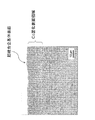
なお、WC基超硬合金製インサート基体のCo富化表面領域の組織写真の一例を図1に示す。
In the above-described conventional method for producing a WC cemented carbide insert, the present inventors, as raw material powder of WC cemented carbide, to WC powder and Co powder having a predetermined particle size,
(A) Zr compound powder, Nb compound powder and Ta compound powder,
(B) Nb and Ta composite compound powder and Zr compound powder,
(C) a composite compound powder of Nb, Ta and Zr,
(D) Nb and Zr composite compound powder and Ta compound powder,
(E) Ta and Zr composite compound powder and Nb compound powder,
At least one of the above (a) to (e) is added as an essential powder component, and then a green compact is produced by press molding. This is, for example, a temperature rising speed of 2 to 10 ° C./min, N 2 The temperature was raised to 1300 ° C. at a pressure of 0.06 to 2.0 KPa, then 35 to 80% of N 2 was replaced with Ar while maintaining the pressure, and the temperature was raised as an N 2 / Ar mixed atmosphere. Sintering is performed under the condition that the temperature is raised to a predetermined temperature between 1400 and 1500 ° C. at a speed of 10 to 20 ° C./min, and then cooled after holding and firing for 45 minutes, and then this is ground, By processing into a predetermined insert shape and honing amount and forming a hard coating layer thereon by vapor deposition, Co having an average thickness of 5 to 35 μm substantially free of Zr is formed on the surface of the insert base made of WC cemented carbide. Enrichment A surface region is formed, and the Co content of the Co-enriched surface region is 1.30 to 2.10 (however, mass ratio) of the Co content inside the cemented carbide. Obtaining the WC cemented carbide insert of the present invention in which the total content of Nb and Ta in the surface region is 0.025 to 0.085 (however, mass ratio) of the Co content in the Co-enriched surface region. Can do.
An example of a structure photograph of the Co-enriched surface region of the WC-based cemented carbide insert substrate is shown in FIG.
そして、上記所定のCo質量比、Nb質量比、Ta質量比を有するCo富化表面領域を備えた本発明の被覆超硬インサートは、切刃に衝撃的かつ断続的高負荷が作用する鋼や鋳鉄の断続重切削加工に用いた場合にも、切刃はこれに満足できる靭性と耐熱塑性変形性を相兼ね備えるため、長時間の使用に亘って、すぐれた耐チッピング性と耐摩耗性を発揮することを見出したのである。 The coated carbide insert of the present invention having a Co-enriched surface region having the predetermined Co mass ratio, Nb mass ratio, and Ta mass ratio is a steel in which impact and intermittent high load are applied to the cutting edge. Even when used for intermittent heavy cutting of cast iron, the cutting edge combines toughness and heat-resistant plastic deformation that satisfy this requirement, so it exhibits excellent chipping resistance and wear resistance over a long period of use. I found out.
本発明は、上記知見に基づいてなされたものであって、
「 原料として少なくともWC粉末、Co粉末を含むとともに、さらに、
(a)Zr化合物粉末、Nb化合物粉末およびTa化合物粉末、
(b)NbとTaの複合化合物粉末とZr化合物粉末、
(c)NbとTaとZrの複合化合物粉末、
(d)NbとZrの複合化合物粉末とTa化合物粉末、
(e)TaとZrの複合化合物粉末とNb化合物粉末、
上記(a)〜(e)のうちの少なくともいずれかを含む配合原料を成形、焼結して得られるWC基超硬合金を基体とし、この基体上に硬質被覆層を蒸着形成した表面被覆超硬合金製インサートにおいて、
上記WC基超硬合金の基体表面には、Zrを含有しない5〜35μmの平均厚さのCo富化表面領域が形成され、かつ、該Co富化表面領域におけるCo含有量は、超硬合金内部のCo含有量の1.30〜2.10(但し、質量比)を満足し、かつ、該Co富化表面領域におけるNbおよびTaの合計含有量は、前記Co富化表面領域におけるCo含有量の0.025〜0.085(但し、質量比)であることを特徴とする表面被覆超硬合金製インサート。」
を特徴とするものである。
The present invention has been made based on the above findings,
"Including at least WC powder and Co powder as raw materials,
(A) Zr compound powder, Nb compound powder and Ta compound powder,
(B) Nb and Ta composite compound powder and Zr compound powder,
(C) a composite compound powder of Nb, Ta and Zr,
(D) Nb and Zr composite compound powder and Ta compound powder,
(E) Ta and Zr composite compound powder and Nb compound powder,
A surface-coated ultra-coating having a WC-based cemented carbide obtained by molding and sintering a blended raw material containing at least any one of the above (a) to (e) as a base, and a hard coating layer formed on the base by vapor deposition In hard alloy inserts,
On the substrate surface of the WC-based cemented carbide, a Co-enriched surface region having an average thickness of 5 to 35 μm that does not contain Zr is formed, and the Co content in the Co-enriched surface region is The internal Co content of 1.30 to 2.10 (however, the mass ratio) is satisfied, and the total content of Nb and Ta in the Co-enriched surface region is the Co content in the Co-enriched surface region. A surface-coated cemented carbide insert characterized in that the amount is 0.025 to 0.085 (however, mass ratio). "
It is characterized by.
本発明の構成について、以下に説明する。 The configuration of the present invention will be described below.
本発明被覆超硬インサートの超硬合金基体は、例えば、所定粒径のWC粉末、Co粉末に、
(a)Zr化合物粉末、Nb化合物粉末およびTa化合物粉末、
(b)NbとTaの複合化合物粉末とZr化合物粉末、
(c)NbとTaとZrの複合化合物粉末、
(d)NbとZrの複合化合物粉末とTa化合物粉末、
(e)TaとZrの複合化合物粉末とNb化合物粉末、
上記(a)〜(e)のうちの少なくともいずれかを必須の粉末成分として添加して、所定配合比の原料粉末を形成した後、バインダーと溶剤を加えて混合し、これを乾燥後、所定圧力で所定形状の圧粉体にプレス成形した後、この圧粉体を、例えば、昇温スピード2〜10℃/min,N2圧力0.06〜2.0KPaにて1200℃まで加熱昇温(一次昇温という)し、ついで、圧力を保持しながら35〜80%のN2をArで置換して、N2/Ar混合雰囲気として、昇温スピード10〜20℃/minで1400〜1500℃の間の所定温度まで加熱昇温(二次昇温という)し、その後、45分間保持焼成後冷却するという条件下で焼結を行い、次いで、これを研削して、所定インサート形状およびホーニング量に加工することにより得る。
原料粉末組成は、質量比で、
WC:Co:Zr化合物:Nb化合物:Ta化合物
=( 70.0〜94.0%):(4.0〜12.0%):(1.0〜7.0%):(0.7〜4.0%):(0.6〜6.5%)
であることが望ましい。
ここで、上記化合物とは、主として、炭化物、窒化物、炭窒化物等をいい、また、複合化合物とは、Nb,Ta,Zrの固溶体化合物をいう。
The cemented carbide substrate of the present invention coated carbide insert is, for example, a WC powder, Co powder of a predetermined particle size,
(A) Zr compound powder, Nb compound powder and Ta compound powder,
(B) Nb and Ta composite compound powder and Zr compound powder,
(C) a composite compound powder of Nb, Ta and Zr,
(D) Nb and Zr composite compound powder and Ta compound powder,
(E) Ta and Zr composite compound powder and Nb compound powder,
After adding at least one of the above (a) to (e) as an essential powder component to form a raw material powder having a predetermined mixing ratio, a binder and a solvent are added and mixed. After press molding into a green compact of a predetermined shape with pressure, the green compact is heated to 1200 ° C. at a temperature rising speed of 2 to 10 ° C./min and an N 2 pressure of 0.06 to 2.0 KPa, for example. Next, 35 to 80% of N 2 is substituted with Ar while maintaining the pressure, and a mixed atmosphere of N 2 / Ar is set to 1400 to 1500 at a heating rate of 10 to 20 ° C./min. Sintering is performed under the condition that the temperature is raised to a predetermined temperature between 2 ° C. (referred to as secondary temperature increase), and then cooled after holding and firing for 45 minutes, and then this is ground to obtain a predetermined insert shape and honing By processing into quantity It can be.
The raw material powder composition is a mass ratio,
WC: Co: Zr compound: Nb compound: Ta compound
= (70.0-94.0%): (4.0-12.0%): (1.0-7.0%): (0.7-4.0%): (0.6- 6.5%)
It is desirable that
Here, the compound mainly refers to carbide, nitride, carbonitride, and the like, and the composite compound refers to a solid solution compound of Nb, Ta, and Zr.
上記の製造法で得られたZr化合物、Nb化合物及びTa化合物が含有されている本発明の超硬合金基体に、当業者に広く知られている硬質被覆層(TiN層、TiCN層、Al2O3層等)を、化学蒸着によって被覆形成することにより、本発明被覆超硬インサートを作製する。
得られた本発明被覆超硬インサートの超硬基体表面と硬質被覆層との界面近傍を、光学顕微鏡を用いて観察すると、図1に示されるように、基体表面には、5〜35μmの平均厚さのCo富化表面領域が形成されていることが観察される。
形成されるCo富化表面領域の厚さは、焼結時の温度、時間、圧力等によって影響されるが、Co富化表面領域が5μmよりも薄くなると、断続重切削加工において、耐チッピング性、耐欠損性の向上が期待できず、一方、Co富化表面領域が35μmよりも厚くなると、耐熱塑性変形性が低下し偏摩耗を生じやすくなることから、Co富化表面領域の平均厚さは、5〜35μmとする。
A hard coating layer (TiN layer, TiCN layer, Al 2 ) widely known to those skilled in the art is applied to the cemented carbide substrate of the present invention containing the Zr compound, Nb compound and Ta compound obtained by the above production method. The coated carbide insert of the present invention is produced by coating the O 3 layer or the like) by chemical vapor deposition.
When the vicinity of the interface between the carbide substrate surface and the hard coating layer of the obtained coated carbide insert of the present invention was observed using an optical microscope, the substrate surface had an average of 5 to 35 μm as shown in FIG. It is observed that a thick Co-enriched surface region is formed.
The thickness of the Co-enriched surface region to be formed is affected by the temperature, time, pressure, etc. during sintering, but if the Co-enriched surface region becomes thinner than 5 μm, chipping resistance in intermittent heavy cutting processing On the other hand, when the Co-enriched surface region is thicker than 35 μm, the heat-resistant plastic deformability is lowered and uneven wear tends to occur. Therefore, the average thickness of the Co-enriched surface region is not expected. Is 5 to 35 μm.
次に、本発明被覆超硬インサートWC基超硬合金基体のCo富化表面領域とWC超硬合金基体内部のCo含有量、Nb含有量及びTa含有量は、以下のようにして測定する。
Co含有量、Nb含有量およびTa含有量の測定は、電子線マイクロアナライザ(以下、EPMAで示す)を用いて、前記WC基超硬合金基体の縦断面にて行った。
上記の測定によると、Co富化表面領域のCo含有量は、超硬合金内部のCo含有量の1.30〜2.10であり、また、Nb含有量およびTa含有量の合計は、前記Co富化表面領域のCo含有量の0.025〜0.085(但し、いずれも質量比)であることがわかる。
Next, the Co-enriched surface region of the coated cemented carbide insert WC-based cemented carbide substrate and the Co content, Nb content and Ta content inside the WC cemented carbide substrate are measured as follows.
The Co content, Nb content, and Ta content were measured in the longitudinal section of the WC-based cemented carbide substrate using an electron beam microanalyzer (hereinafter referred to as EPMA).
According to the above measurement, the Co content in the Co-enriched surface region is 1.30 to 2.10 of the Co content inside the cemented carbide, and the total of the Nb content and the Ta content is It turns out that it is 0.025-0.085 Co (however, all are mass ratios) of Co content of Co enriched surface area | region.
Co富化表面領域のCo含有量は、焼結条件、特に、一次昇温時のN2圧力、二次昇温および焼成時のN2/Ar混合ガス中のN2とArの混合比によって、以下のように大きく影響される。
一次昇温時のN2圧力と、二次昇温および焼成時のN2/Ar混合ガス中のN2分圧の差が大きいと、Co富化表面領域のCo含有量が相対的に高くなる。逆に、一次昇温時のN2圧力と、二次昇温および焼成時のN2/Ar混合ガス中のN2分圧の差が小さいと、Co富化表面領域のCo含有量が相対的に低くなる。
また、Co富化表面領域におけるNb含有量、Ta含有量は、焼結条件、特に、一次昇温時のN2圧力と、二次昇温および焼成時のN2/Ar混合ガス中のN2とArの混合比に加えて、二次昇温時の昇温スピードによって、以下のように大きく影響される。
一次昇温時のN2圧力と、二次昇温および焼成時のN2/Ar混合ガス中のN2分圧の差が大きく、二次昇温時の昇温スピードが高いと、Co富化表面領域のNb含有量、Ta含有量が相対的に高くなる。逆に、一次昇温時のN2圧力と、二次昇温および焼成時のN2/Ar混合ガス中のN2分圧の差が小さく、二次昇温時の昇温スピードが低いと、Co富化表面領域のNb含有量、Ta含有量が相対的に低くなる。
The Co content in the Co-enriched surface region depends on the sintering conditions, in particular, the N 2 pressure at the time of primary temperature rise, the secondary temperature rise and the mixing ratio of N 2 and Ar in the N 2 / Ar mixed gas at the time of firing. It is greatly affected as follows.
And N 2 pressure during primary heating, the difference of the secondary heating and baking time of N 2 / Ar N 2 partial pressure in the mixed gas is large, Co content of Co-enriched surface region is relatively high Become. Conversely, the N 2 pressure during primary heating, the difference of the secondary heating and baking time of N 2 / Ar N 2 partial pressure in the mixed gas is small, Co content of Co-enriched surface region relative Lower.
Further, the Nb content and the Ta content in the Co-enriched surface region are determined based on the sintering conditions, in particular, the N 2 pressure at the time of primary temperature rise, and the N 2 / Ar mixed gas at the time of secondary temperature rise and firing. In addition to the mixing ratio of 2 and Ar, the temperature rise speed at the time of secondary temperature rise is greatly affected as follows.
And N 2 pressure during primary heating, large differences in the secondary heating and baking time of N 2 / Ar N 2 partial pressure in the mixed gas, the high Atsushi Nobori speed at the time of the secondary heating, Co wealth The Nb content and Ta content in the chemical surface area are relatively high. Conversely, the N 2 pressure during primary heating, small difference in secondary Atsushi Nobori and baking time of N 2 / Ar N 2 partial pressure in the mixed gas, when the low heating speed during the secondary heating The Nb content and the Ta content in the Co-enriched surface region are relatively low.
Co富化表面領域におけるCo含有量が1.30未満であると、Co富化表面領域の靭性が不十分であって、耐チッピング性、耐欠損性の向上を期待することはできず、一方、Co富化表面領域におけるCo含有量が2.10を超えると、Co富化表面領域の耐熱塑性変形性が低下傾向を示すようになるため、偏摩耗が発生しやすくなり、耐摩耗性が劣化することから、Co富化表面領域のCo含有量は、超硬合金内部のCo含有量の1.30〜2.10(但し、質量比)と定めた。
さらに、Co富化表面領域の耐熱塑性変形性の良否は、Co富化表面領域に存在するNb成分、Ta成分とNb含有量、Ta含有量が大きな影響を与える。即ち、焼結後の超硬基体のCo富化表面領域に、前記Co富化表面領域におけるCo含有量に対して0.025〜0.085(但し、質量比)のNb、Taが存在すると、Co富化表面領域の耐熱塑性変形性が向上する。しかし、前記Co富化表面領域のCo含有量に対するNb含有量、Ta含有量の合計量が0.025未満の場合には、Nb、TaによるCo強度向上の作用が不十分となり、所望のCo富化表面領域の耐熱塑性変形性を確保できなくなることから偏摩耗が発生しやすくなり、一方、Co富化表面領域のNb含有量、Ta含有量の合計量が0.085を超えるような場合には、相対的にCo富化表面領域の靭性が低下するためにチッピングや欠損が発生しやすくなることから、Co富化表面領域のNb含有量、Ta含有量の合計量は、Co富化表面領域のCo含有量に対して0.025〜0.085(但し、質量比)と定めた。
なお、この発明の超硬合金の必須成分として含有しているZr化合物については、WCを含む炭化物の強固なスケルトン構造を形成し、その結果として、耐熱塑性変形性を向上させるが、Co富化表面領域中に多量のZrが存在すると、焼結性が低下するばかりか靭性も低下し、チッピング発生の起点となりやすい。
ただ、前記した本発明の超硬合金の焼結条件によれば、Co富化表面領域中のZr含有量は、実質的にゼロとなるため、耐チッピング性および耐熱塑性変形性に悪影響を及ぼすことはない。
If the Co content in the Co-enriched surface region is less than 1.30, the toughness of the Co-enriched surface region is insufficient, and improvement in chipping resistance and fracture resistance cannot be expected. When the Co content in the Co-enriched surface region exceeds 2.10, the heat-resistant plastic deformability of the Co-enriched surface region tends to decrease, so that uneven wear is likely to occur and the wear resistance is improved. Because of deterioration, the Co content in the Co-enriched surface region was determined to be 1.30 to 2.10 (however, mass ratio) of the Co content inside the cemented carbide.
Furthermore, the quality of heat-resistant plastic deformation of the Co-enriched surface region is greatly influenced by the Nb component, Ta component and Nb content, and Ta content existing in the Co-enriched surface region. That is, if the Co-enriched surface region of the cemented carbide substrate after sintering contains 0.025 to 0.085 (but mass ratio) of Nb and Ta with respect to the Co content in the Co-enriched surface region. The heat-resistant plastic deformation property of the Co-enriched surface region is improved. However, when the total amount of Nb content and Ta content relative to the Co content of the Co-enriched surface region is less than 0.025, the effect of improving the Co strength by Nb and Ta becomes insufficient, and the desired Co When the heat resistance plastic deformation property of the enriched surface region cannot be ensured, uneven wear tends to occur. On the other hand, when the total amount of Nb content and Ta content of the Co enriched surface region exceeds 0.085 Since the toughness of the Co-enriched surface region is relatively reduced, chipping and defects are likely to occur. Therefore, the total amount of Nb content and Ta content of the Co-enriched surface region is Co-enriched. It was set as 0.025-0.085 (however, mass ratio) with respect to Co content of a surface area | region.
In addition, about the Zr compound contained as an essential component of the cemented carbide of the present invention, a strong skeleton structure of carbide containing WC is formed, and as a result, the heat-resistant plastic deformability is improved, but Co enrichment When a large amount of Zr is present in the surface region, not only the sinterability is lowered, but also the toughness is lowered, which tends to be a starting point for occurrence of chipping.
However, according to the sintering conditions of the cemented carbide of the present invention described above, the Zr content in the Co-enriched surface region is substantially zero, which adversely affects chipping resistance and heat-resistant plastic deformation. There is nothing.
本発明の表面被覆超硬合金製インサートによれば、特に、Co富化表面領域のCo含有量は、超硬合金内部のCo含有量の1.30〜2.10(但し、質量比)であり、かつ、Co富化表面領域のNb含有量、Ta含有量の合計量は、前記Co富化表面領域のCo含有量の0.025〜0.085(但し、質量比)とされ、Co富化表面領域が靭性と耐熱塑性変形性を相兼ね備えることにより、切刃に衝撃的かつ断続的高負荷が作用する鋼や鋳鉄等の断続重切削加工において、硬質被覆層がすぐれた耐チッピング性と耐熱塑性変形性を示し、その結果、長期の使用にわたってすぐれた耐摩耗性を発揮することができる。 According to the insert made of the surface-coated cemented carbide of the present invention, in particular, the Co content in the Co-enriched surface region is 1.30 to 2.10 (however, mass ratio) of the Co content inside the cemented carbide. And the total amount of Nb content and Ta content in the Co-enriched surface region is 0.025 to 0.085 (however, mass ratio) of the Co content in the Co-enriched surface region. Chipping resistance with excellent hard coating layer in intermittent heavy cutting of steel, cast iron, etc. where impact and intermittent high load acts on the cutting edge due to the combination of toughness and heat-resistant plastic deformation As a result, excellent wear resistance can be exhibited over a long period of use.
次に、本発明の表面被覆超硬合金製インサートについて、実施例により具体的に説明する。 Next, the surface-coated cemented carbide insert of the present invention will be specifically described with reference to examples.
原料粉末として、いずれも0.5〜3μmの範囲内の所定の平均粒径を有するWC粉末、Co粉末、ZrC粉末、ZrCN粉末、NbC粉末、NbCN粉末、TaC粉末、TaCN粉末、Cr3C2粉末を、表1に示される割合に配合し、さらにバインダーと溶剤を加えてアセトン中で24時間ボールミル混合し、減圧乾燥した後、100MPaの圧力で所定形状の圧粉体にプレス成形した。
このプレス成形により得た圧粉体を、表2に示す焼結条件で焼結し、本発明の被覆超硬インサート素材1〜10を製造した。
これらの被覆超硬インサート素材から研削にて、CNMG120408(ホーニング量0.07mm)に規定されるインサート形状およびホーニング量に加工し、本発明の被覆超硬インサート基体1〜10を製造した。
As raw material powders, WC powder, Co powder, ZrC powder, ZrCN powder, NbC powder, NbCN powder, TaC powder, TaCN powder, Cr 3 C 2 all having a predetermined average particle diameter in the range of 0.5 to 3 μm. The powder was blended in the proportions shown in Table 1, a binder and a solvent were further added, ball milled in acetone for 24 hours, dried under reduced pressure, and then pressed into a green compact having a predetermined shape at a pressure of 100 MPa.
The green compact obtained by this press molding was sintered under the sintering conditions shown in Table 2 to produce coated carbide insert materials 1 to 10 of the present invention.
The coated carbide insert bases 1 to 10 of the present invention were manufactured by grinding from these coated cemented carbide insert materials into an insert shape and a honing amount defined in CNMG120408 (honing amount 0.07 mm).
さらに、上記本発明の被覆超硬インサート基体1〜10の表面に、各種の硬質被覆層を形成し、表3に示す本発明の表面被覆超硬合金製インサート1〜10(以下、実施例1〜10という)を製造した。
実施例1〜10の表面被覆超硬合金製インサートについて、それぞれの超硬インサート基体の表面のCo富化表面領域の厚さを、前記超硬インサートを縦断面方向に鏡面ラップした後に光学顕微鏡観察によって求めた。
なお、図1に、本発明の表面被覆超硬合金製インサート5の超硬基体表面の断面光学顕微鏡写真を示す。
さらに、実施例1〜10の表面被覆超硬合金製インサートの内部のCo含有量、Nb含有量、Ta含有量、Zr含有量、また、Co富化表面領域のCo含有量、Nb含有量、Ta含有量、Zr含有量を、前記本発明超硬合金製インサートの縦断面における当該箇所をEPMAにより測定し求めるとともに、各種の含有比率、即ち、(Co富化表面領域のCo含有量)/(超硬合金内部のCo含有量),(Co富化表面領域のNb含有量)/(Co富化表面領域のCo含有量),(Co富化表面領域のTa含有量)/(Co富化表面領域のCo含有量),((Co富化表面領域のNb含有量)+(Co富化表面領域のTa含有量))/(Co富化表面領域のCo含有量)を求めた。
これらの結果を、表3に示す。
Further, various hard coating layers are formed on the surfaces of the coated carbide insert bases 1 to 10 of the present invention, and the surface-coated cemented carbide inserts 1 to 10 of the present invention shown in Table 3 (hereinafter referred to as Example 1). To 10).
For the surface-coated cemented carbide inserts of Examples 1 to 10, the thickness of the Co-enriched surface region of the surface of each cemented carbide insert substrate was observed with an optical microscope after the cemented carbide insert was mirror-wrapped in the longitudinal section direction. Sought by.
FIG. 1 shows a cross-sectional optical micrograph of the surface of the cemented carbide substrate of the surface-coated cemented carbide insert 5 of the present invention.
Furthermore, the Co content, Nb content, Ta content, Zr content inside the surface-coated cemented carbide inserts of Examples 1 to 10, and the Co content in the Co-enriched surface region, the Nb content, The Ta content and the Zr content are determined by measuring the corresponding locations in the longitudinal section of the cemented carbide insert of the present invention with EPMA, and various content ratios, that is, (Co content of Co-enriched surface region) / (Co content inside cemented carbide), (Nb content in Co-enriched surface region) / (Co content in Co-enriched surface region), (Ta content in Co-enriched surface region) / (Co-rich Co content in the enriched surface region), ((Nb content in the Co enriched surface region) + (Ta content in the Co enriched surface region)) / (Co content in the Co enriched surface region).
These results are shown in Table 3.

比較のため、原料粉末として、いずれも0.5〜3μmの範囲内の所定の平均粒径を有するWC粉末、Co粉末、ZrC粉末、ZrCN粉末、NbC粉末、NbCN粉末、TaC粉末、TaCN粉末、Cr3C2粉末を、表4に示される割合に配合し、さらにバインダーと溶剤を加えてアセトン中で24時間ボールミル混合し、減圧乾燥した後、100MPaの圧力で所定形状の圧粉体にプレス成形し、 このプレス成形により得た圧粉体を、表5に示す焼結条件で焼結し、比較例の被覆超硬インサート素材1〜10を製造した。
これらの被覆超硬インサート素材から研削にて、CNMG120408(ホーニング量0.07mm)に規定されるインサート形状およびホーニング量に加工し、比較例の被覆超硬インサート基体1〜10を製造した。
For comparison, as raw material powders, WC powder, Co powder, ZrC powder, ZrCN powder, NbC powder, NbCN powder, TaC powder, TaCN powder, all having a predetermined average particle diameter in the range of 0.5 to 3 μm, Cr 3 C 2 powder is blended in the proportions shown in Table 4, and a binder and a solvent are added, followed by ball mill mixing in acetone for 24 hours, dried under reduced pressure, and then pressed into a green compact of a predetermined shape at a pressure of 100 MPa. The green compact obtained by press molding was sintered under the sintering conditions shown in Table 5 to produce coated carbide insert materials 1 to 10 of comparative examples.
The coated carbide insert bases 1 to 10 of the comparative examples were manufactured by grinding from these coated carbide insert materials into an insert shape and a honing amount specified in CNMG120408 (a honing amount of 0.07 mm).
さらに、上記比較例の被覆超硬インサート基体1〜10の表面に、各種の硬質被覆層を形成し、表6に示す比較例の表面被覆超硬合金製インサート1〜10(以下、比較例1〜10という)を製造した。
比較例1〜10の表面被覆超硬合金製インサートについて、それぞれの超硬インサート基体の表面のCo富化表面領域の厚さを、前記比較超硬インサートを鏡面ラップした後に光学顕微鏡観察によって求めた。
さらに、比較例1〜10の表面被覆超硬合金製インサートの内部のCo含有量、Nb含有量、Ta含有量、Zr含有量、また、Co富化表面領域のCo含有量、Nb含有量、Ta含有量、Zr含有量を、前記比較例超硬合金製インサートの縦断面における当該箇所をEPMAにより測定し求めるとともに、各種の含有比率、即ち、(Co富化表面領域のCo含有量)/(超硬合金内部のCo含有量),(Co富化表面領域のNb含有量)/(Co富化表面領域のCo含有量),(Co富化表面領域のTa含有量)/(Co富化表面領域のCo含有量),((Co富化表面領域のNb含有量)+(Co富化表面領域のTa含有量))/(Co富化表面領域のCo含有量)を求めた。
これらの結果を、表6に示す。
Further, various hard coating layers are formed on the surfaces of the coated cemented carbide insert bases 1 to 10 of the comparative example, and the surface coated cemented carbide inserts 1 to 10 of the comparative examples shown in Table 6 (hereinafter referred to as Comparative Example 1). To 10).
For the surface-coated cemented carbide inserts of Comparative Examples 1 to 10, the thickness of the Co-enriched surface region of the surface of each cemented carbide insert substrate was determined by optical microscope observation after the comparative cemented carbide insert was mirror-wrapped. .
Furthermore, the Co content, Nb content, Ta content, Zr content in the interior of the surface-coated cemented carbide inserts of Comparative Examples 1 to 10, and the Co content in the Co-enriched surface region, the Nb content, The Ta content and the Zr content are determined by measuring the corresponding part in the longitudinal section of the comparative cemented carbide insert by EPMA, and various content ratios, that is, (Co content of Co-enriched surface region) / (Co content inside cemented carbide), (Nb content in Co-enriched surface region) / (Co content in Co-enriched surface region), (Ta content in Co-enriched surface region) / (Co-rich Co content in the enriched surface region), ((Nb content in the Co enriched surface region) + (Ta content in the Co enriched surface region)) / (Co content in the Co enriched surface region).
These results are shown in Table 6.
つぎに、上記の実施例1〜10および比較例1〜10について、いずれも工具鋼製バイトの先端部に固定治具にてネジ止めした状態で、
被削材:JIS・S45Cの2溝スリット入り丸棒、
切削速度:400 m/min.、
切り込み:2.0 mm、
送り:0.30 mm/rev.、
の条件(以下、切削条件1という)での炭素鋼の乾式高速断続切削加工試験(通常の切削速度は、200m/min.)、
被削材:JIS・SNCM439の2溝スリット入り丸棒、
切削速度:350 m/min.、
切り込み:3.0 mm、
送り:0.25 mm/rev.、
の条件(以下、切削条件2という)での合金鋼の乾式断続高切込み切削加工試験(通常の切り込みは、1.5mm)、
を行い、
逃げ面摩耗幅が0.3mmに達するまでの時間を測定した。
これらの切削加工試験結果を表7に示した。
Next, for the above Examples 1-10 and Comparative Examples 1-10, both are screwed to the tip of the tool steel tool with a fixing jig,
Work material: JIS / S45C round bar with 2 groove slit,
Cutting speed: 400 m / min. ,
Cutting depth: 2.0 mm,
Feed: 0.30 mm / rev. ,
Dry high-speed intermittent cutting test of carbon steel under the following conditions (hereinafter referred to as cutting condition 1) (normal cutting speed is 200 m / min.),
Work material: JIS / SNCM439 round bar with 2 groove slit,
Cutting speed: 350 m / min. ,
Cutting depth: 3.0 mm,
Feed: 0.25 mm / rev. ,
Dry intermittent high cutting cutting test of alloy steel under the following conditions (hereinafter referred to as cutting condition 2) (normal cutting is 1.5 mm),
And
The time until the flank wear width reached 0.3 mm was measured.
These cutting test results are shown in Table 7.
表3,6,7の結果からみて、本発明の表面被覆超硬合金製インサートにおいては、特に、Co含有量の質量比が1.30〜2.10となっているCo富化表面領域が形成され、さらに、該Co富化表面領域におけるCo含有量に対するNb含有量およびTa含有量の合計が質量比で、0.025〜0.085となっているCo富化表面領域が形成されていることによって、切刃に断続的かつ衝撃的高負荷が作用する鋼や鋳鉄等の断続重切削加工において、すぐれた耐チッピング性および耐熱塑性変形性を示し、その結果、長期の使用にわたって欠損、偏摩耗等を発生することなくすぐれた耐摩耗性を発揮することができるのに対して、比較例の表面被覆超硬合金製インサートでは、チッピングの発生あるいは耐摩耗性の劣化によって、短時間で寿命に至ることは明らかである。 From the results of Tables 3, 6, and 7, in the surface-coated cemented carbide insert of the present invention, the Co-enriched surface region in which the mass ratio of Co content is 1.30 to 2.10. Further, a Co-enriched surface region is formed in which the sum of the Nb content and the Ta content with respect to the Co content in the Co-enriched surface region is 0.025 to 0.085 by mass ratio. It shows excellent chipping resistance and heat plastic deformation in intermittent heavy cutting such as steel and cast iron where intermittent and impact high loads act on the cutting edge. Excellent wear resistance can be exhibited without causing uneven wear, etc., while the surface-coated cemented carbide insert of the comparative example has a short time due to occurrence of chipping or deterioration of wear resistance. In can lead to life is clear.
本発明の表面被覆超硬合金製インサートは、断続重切削加工に用いられた場合、長期間の使用にわたってすぐれた切削性能を維持することができるばかりでなく、工具寿命の延命化も図られ、さらに、本発明の表面被覆超硬合金製インサートは、耐チッピング性、耐欠損性、耐熱塑性変形性、耐摩耗性等が求められる各種被削材のインサートとして用いることが可能であり、切削加工の省エネ化、低コスト化に十分満足に対応できるものである。
When the surface-coated cemented carbide insert of the present invention is used for intermittent heavy cutting, not only can excellent cutting performance be maintained over a long period of use, but also the tool life can be extended. Furthermore, the surface-coated cemented carbide insert of the present invention can be used as an insert for various work materials that require chipping resistance, chipping resistance, heat plastic deformation, wear resistance, etc. It can cope with energy saving and cost reduction.
Claims (1)
(a)Zr化合物粉末、Nb化合物粉末およびTa化合物粉末、
(b)NbとTaの複合化合物粉末とZr化合物粉末、
(c)NbとTaとZrの複合化合物粉末、
(d)NbとZrの複合化合物粉末とTa化合物粉末、
(e)TaとZrの複合化合物粉末とNb化合物粉末、
上記(a)〜(e)のうちの少なくともいずれかを含む配合原料を成形、焼結して得られるWC基超硬合金を基体とし、この基体上に硬質被覆層を蒸着形成した表面被覆超硬合金製インサートにおいて、
上記WC基超硬合金の基体表面には、Zrを含有しない5〜35μmの平均厚さのCo富化表面領域が形成され、かつ、該Co富化表面領域におけるCo含有量は、超硬合金内部のCo含有量の1.30〜2.10(但し、質量比)を満足し、かつ、該Co富化表面領域におけるNbおよびTaの合計含有量は、前記Co富化表面領域におけるCo含有量の0.025〜0.085(但し、質量比)であることを特徴とする表面被覆超硬合金製インサート。
In addition to containing at least WC powder and Co powder as raw materials,
(A) Zr compound powder, Nb compound powder and Ta compound powder,
(B) Nb and Ta composite compound powder and Zr compound powder,
(C) a composite compound powder of Nb, Ta and Zr,
(D) Nb and Zr composite compound powder and Ta compound powder,
(E) Ta and Zr composite compound powder and Nb compound powder,
A surface-coated ultra-coating having a WC-based cemented carbide obtained by molding and sintering a blended raw material containing at least any one of the above (a) to (e) as a base, and a hard coating layer formed on the base by vapor deposition In hard alloy inserts,
On the substrate surface of the WC-based cemented carbide, a Co-enriched surface region having an average thickness of 5 to 35 μm that does not contain Zr is formed, and the Co content in the Co-enriched surface region is The internal Co content of 1.30 to 2.10 (however, the mass ratio) is satisfied, and the total content of Nb and Ta in the Co-enriched surface region is the Co content in the Co-enriched surface region. A surface-coated cemented carbide insert characterized in that the amount is 0.025 to 0.085 (however, mass ratio).
Priority Applications (4)
| Application Number | Priority Date | Filing Date | Title |
|---|---|---|---|
| JP2010206501A JP5561607B2 (en) | 2010-09-15 | 2010-09-15 | Surface-coated WC-based cemented carbide insert |
| EP11825043.0A EP2617504B1 (en) | 2010-09-15 | 2011-09-07 | Surface-coated insert made of wc-based cemented carbide |
| PCT/JP2011/070346 WO2012036037A1 (en) | 2010-09-15 | 2011-09-07 | Surface coating insert made of wc-based cemented carbide |
| US13/822,101 US9023467B2 (en) | 2010-09-15 | 2011-09-07 | Surface-coated WC-based cemented carbide insert |
Applications Claiming Priority (1)
| Application Number | Priority Date | Filing Date | Title |
|---|---|---|---|
| JP2010206501A JP5561607B2 (en) | 2010-09-15 | 2010-09-15 | Surface-coated WC-based cemented carbide insert |
Publications (2)
| Publication Number | Publication Date |
|---|---|
| JP2012061536A JP2012061536A (en) | 2012-03-29 |
| JP5561607B2 true JP5561607B2 (en) | 2014-07-30 |
Family
ID=45831504
Family Applications (1)
| Application Number | Title | Priority Date | Filing Date |
|---|---|---|---|
| JP2010206501A Active JP5561607B2 (en) | 2010-09-15 | 2010-09-15 | Surface-coated WC-based cemented carbide insert |
Country Status (4)
| Country | Link |
|---|---|
| US (1) | US9023467B2 (en) |
| EP (1) | EP2617504B1 (en) |
| JP (1) | JP5561607B2 (en) |
| WO (1) | WO2012036037A1 (en) |
Families Citing this family (2)
| Publication number | Priority date | Publication date | Assignee | Title |
|---|---|---|---|---|
| JP6395053B2 (en) * | 2015-03-24 | 2018-09-26 | 三菱マテリアル株式会社 | Surface-coated WC-based cemented carbide cutting tool with excellent fracture resistance and plastic deformation resistance |
| CN108607999B (en) * | 2018-06-14 | 2021-04-23 | 陕西理工大学 | Preparation method of multilayer easy-to-weld large-gradient hard alloy material |
Family Cites Families (19)
| Publication number | Priority date | Publication date | Assignee | Title |
|---|---|---|---|---|
| US4282289A (en) * | 1980-04-16 | 1981-08-04 | Sandvik Aktiebolag | Method of preparing coated cemented carbide product and resulting product |
| US4399168A (en) * | 1980-01-21 | 1983-08-16 | Santrade Ltd. | Method of preparing coated cemented carbide product |
| US4610931A (en) * | 1981-03-27 | 1986-09-09 | Kennametal Inc. | Preferentially binder enriched cemented carbide bodies and method of manufacture |
| US4828612A (en) * | 1987-12-07 | 1989-05-09 | Gte Valenite Corporation | Surface modified cemented carbides |
| US5250367A (en) * | 1990-09-17 | 1993-10-05 | Kennametal Inc. | Binder enriched CVD and PVD coated cutting tool |
| SE514737C2 (en) * | 1994-03-22 | 2001-04-09 | Sandvik Ab | Coated carbide cutting tool |
| US5955186A (en) * | 1996-10-15 | 1999-09-21 | Kennametal Inc. | Coated cutting insert with A C porosity substrate having non-stratified surface binder enrichment |
| US6217992B1 (en) * | 1999-05-21 | 2001-04-17 | Kennametal Pc Inc. | Coated cutting insert with a C porosity substrate having non-stratified surface binder enrichment |
| US6638474B2 (en) * | 2000-03-24 | 2003-10-28 | Kennametal Inc. | method of making cemented carbide tool |
| US6554548B1 (en) * | 2000-08-11 | 2003-04-29 | Kennametal Inc. | Chromium-containing cemented carbide body having a surface zone of binder enrichment |
| SE522730C2 (en) * | 2000-11-23 | 2004-03-02 | Sandvik Ab | Method for manufacturing a coated cemented carbide body intended for cutting machining |
| JP4034931B2 (en) * | 2000-11-29 | 2008-01-16 | 京セラ株式会社 | Coated cemented carbide member and method for producing the same |
| JP2003113437A (en) | 2001-10-03 | 2003-04-18 | Dijet Ind Co Ltd | Hard metal alloy, tool for plastic working, and machining tool |
| SE0103970L (en) | 2001-11-27 | 2003-05-28 | Seco Tools Ab | Carbide metal with binder phase enriched surface zone |
| SE526604C2 (en) * | 2002-03-22 | 2005-10-18 | Seco Tools Ab | Coated cutting tool for turning in steel |
| JP2005206912A (en) * | 2004-01-26 | 2005-08-04 | Hitachi Tool Engineering Ltd | Coated-cemented carbide member |
| JP2005248265A (en) * | 2004-03-05 | 2005-09-15 | Hitachi Tool Engineering Ltd | Coated cemented carbide member |
| JP2005248309A (en) * | 2004-03-08 | 2005-09-15 | Tungaloy Corp | Cemented carbide and coated cemented carbide |
| SE532044C2 (en) * | 2007-12-27 | 2009-10-06 | Seco Tools Ab | Use of a CVD coated cutter when milling |
-
2010
- 2010-09-15 JP JP2010206501A patent/JP5561607B2/en active Active
-
2011
- 2011-09-07 WO PCT/JP2011/070346 patent/WO2012036037A1/en active Application Filing
- 2011-09-07 EP EP11825043.0A patent/EP2617504B1/en active Active
- 2011-09-07 US US13/822,101 patent/US9023467B2/en active Active
Also Published As
| Publication number | Publication date |
|---|---|
| US9023467B2 (en) | 2015-05-05 |
| JP2012061536A (en) | 2012-03-29 |
| US20130177776A1 (en) | 2013-07-11 |
| EP2617504A1 (en) | 2013-07-24 |
| EP2617504A4 (en) | 2015-07-01 |
| WO2012036037A1 (en) | 2012-03-22 |
| EP2617504B1 (en) | 2017-07-12 |
Similar Documents
| Publication | Publication Date | Title |
|---|---|---|
| JP2014188598A (en) | Surface coated wc base super hard alloy cutting tool excellent in toughness and defect resistance | |
| JP2009066741A (en) | Cutting tool made of wc-based cemented carbide excellent in chipping resistance | |
| JP5561607B2 (en) | Surface-coated WC-based cemented carbide insert | |
| JP2011156645A (en) | Surface-coated cutting tool made of wc-based cemented carbide excellent in thermal plastic deformation resistance | |
| JP5003308B2 (en) | Surface coated cutting tool | |
| JP5023896B2 (en) | Surface coated cutting tool | |
| JP6052502B2 (en) | Surface coated cemented carbide cutting tool | |
| JP5517100B2 (en) | Surface-coated WC-based cemented carbide insert | |
| JP5613888B2 (en) | Surface-coated WC-based cemented carbide insert | |
| JP5023895B2 (en) | Surface coated cutting tool | |
| JP2008080476A (en) | Surface coated cutting tool with hard coated layer exerting excellent abrasion resistance in high speed cutting work | |
| JP5023897B2 (en) | Surface coated cutting tool | |
| JP4863071B2 (en) | Surface coated cutting tool with excellent wear resistance due to hard coating layer | |
| JP5561522B2 (en) | Surface-coated WC-based cemented carbide insert | |
| JP4936211B2 (en) | Surface-coated cutting tool whose hard coating layer exhibits excellent wear resistance in high-speed cutting | |
| JP2011195846A (en) | Surface-coated cutting tool made from wc-base cemented carbide | |
| JP5569739B2 (en) | Surface coated cutting tool with excellent chipping resistance | |
| JP2012143829A (en) | Surface-coated wc-based cemented carbide cutting tool | |
| JP7037121B2 (en) | Surface-coated TiN-based cermet cutting tool with excellent chipping resistance due to the hard coating layer | |
| JP5088481B2 (en) | Surface coated cutting tool with excellent wear resistance with hard coating layer in heavy cutting | |
| JP4849233B2 (en) | Surface coated cutting tool with excellent chipping resistance due to hard coating layer | |
| JP4210931B2 (en) | Surface-coated throw-away tip that exhibits excellent chipping resistance with a hard coating layer in high-speed intermittent cutting | |
| JP2005262323A (en) | Surface-coated cermet cutting tool with hard coating layer having excellent chipping resistance | |
| JP2015182155A (en) | Surface-coated cutting tool with hard coating layer exhibiting superior chipping resistance in intermittent cutting | |
| JP2005288639A (en) | Machining tool made of surface-covered thermet with its hard covering layer exerting excellent anti-chipping performance in high-speed intermittent machining of hard-to-machine material |
Legal Events
| Date | Code | Title | Description |
|---|---|---|---|
| A621 | Written request for application examination |
Free format text: JAPANESE INTERMEDIATE CODE: A621 Effective date: 20130329 |
|
| A131 | Notification of reasons for refusal |
Free format text: JAPANESE INTERMEDIATE CODE: A131 Effective date: 20140203 |
|
| A521 | Request for written amendment filed |
Free format text: JAPANESE INTERMEDIATE CODE: A523 Effective date: 20140402 |
|
| TRDD | Decision of grant or rejection written | ||
| A01 | Written decision to grant a patent or to grant a registration (utility model) |
Free format text: JAPANESE INTERMEDIATE CODE: A01 Effective date: 20140516 |
|
| A61 | First payment of annual fees (during grant procedure) |
Free format text: JAPANESE INTERMEDIATE CODE: A61 Effective date: 20140529 |
|
| R150 | Certificate of patent or registration of utility model |
Ref document number: 5561607 Country of ref document: JP Free format text: JAPANESE INTERMEDIATE CODE: R150 |