JP5487053B2 - refrigerator - Google Patents

refrigerator Download PDF

Info

Publication number
JP5487053B2
JP5487053B2 JP2010187782A JP2010187782A JP5487053B2 JP 5487053 B2 JP5487053 B2 JP 5487053B2 JP 2010187782 A JP2010187782 A JP 2010187782A JP 2010187782 A JP2010187782 A JP 2010187782A JP 5487053 B2 JP5487053 B2 JP 5487053B2
Authority
JP
Japan
Prior art keywords
cooler
cold air
temperature zone
defrosting
refrigerator
Prior art date
Legal status (The legal status is an assumption and is not a legal conclusion. Google has not performed a legal analysis and makes no representation as to the accuracy of the status listed.)
Active
Application number
JP2010187782A
Other languages
Japanese (ja)
Other versions
JP2012047362A (en
JP2012047362A5 (en
Inventor
昭義 大平
良二 河井
寛人 石渡
浩和 中村
Current Assignee (The listed assignees may be inaccurate. Google has not performed a legal analysis and makes no representation or warranty as to the accuracy of the list.)
Hitachi Appliances Inc
Original Assignee
Hitachi Appliances Inc
Priority date (The priority date is an assumption and is not a legal conclusion. Google has not performed a legal analysis and makes no representation as to the accuracy of the date listed.)
Filing date
Publication date
Application filed by Hitachi Appliances Inc filed Critical Hitachi Appliances Inc
Priority to JP2010187782A priority Critical patent/JP5487053B2/en
Publication of JP2012047362A publication Critical patent/JP2012047362A/en
Publication of JP2012047362A5 publication Critical patent/JP2012047362A5/ja
Application granted granted Critical
Publication of JP5487053B2 publication Critical patent/JP5487053B2/en
Active legal-status Critical Current
Anticipated expiration legal-status Critical

Links

Images

Description

本発明は、冷蔵庫に関する。   The present invention relates to a refrigerator.

本技術分野の背景技術として、特開2006−183897号公報(特許文献1)及び特開2010−60188号公報(特許文献2)がある。   As background art of this technical field, there are JP-A-2006-183897 (Patent Document 1) and JP-A-2010-60188 (Patent Document 2).

特許文献1に記載の冷蔵庫では、着霜がない状態において通風抵抗の増加を伴わずに熱交換性能を向上させ、着霜が生じた場合であっても実使用状態における熱交換性能を確保できる冷却器形状と、その周囲風路構造について述べている。すなわち、冷却器よりも上方部に設けた貯蔵室(冷蔵室,野菜室)の拡大を主な目的として、従来冷却器よりも奥行きを大きくして高さ方向を低くした冷却器を採用している。   In the refrigerator described in Patent Literature 1, heat exchange performance is improved without increasing ventilation resistance in the absence of frost, and heat exchange performance in actual use can be ensured even when frost formation occurs. It describes the cooler shape and its surrounding air path structure. That is, for the main purpose of expanding the storage room (refrigeration room, vegetable room) provided above the cooler, a cooler with a larger depth and lower height than the conventional cooler is adopted. Yes.

特許文献2に記載の冷蔵庫では、除霜時に貯蔵室の温度上昇を抑えた省エネ性が高い冷蔵庫について述べている。冷却器の前方に冷凍室を設けた冷蔵庫では、除霜ヒータ設置位置よりも上方に冷凍室冷気戻り口を設けている場合が多く、除霜ヒータで加熱された空気が冷凍室冷気戻り口から冷凍室に流出し易くなる。加熱された空気が冷凍室に直接流出することがないように、冷凍室背面部材と冷却器前面側に設けた冷却器カバーとの間に空間を設けて、冷凍室へ直接加熱空気が流出しないように、加熱空気の抑制を行っている。   The refrigerator described in Patent Document 2 describes a refrigerator with high energy saving performance that suppresses the temperature rise of the storage room during defrosting. In a refrigerator having a freezer compartment in front of a cooler, a freezer compartment cool air return port is often provided above the defrost heater installation position, and the air heated by the defrost heater is from the freezer compartment cool air return port. It tends to flow out into the freezer compartment. In order to prevent heated air from flowing directly into the freezer compartment, a space is provided between the freezer compartment back member and the cooler cover provided on the front side of the cooler so that the heated air does not flow directly into the freezer compartment. As described above, the heated air is suppressed.

以上のように通常冷却時と除霜時の省エネルギー化を図るために、冷蔵庫の冷却器形状やその周囲構造に関する特許文献が複数ある。   As described above, in order to save energy during normal cooling and defrosting, there are a plurality of patent documents relating to the refrigerator shape of the refrigerator and its surrounding structure.

特開2006−183897号公報JP 2006-183897 A 特開2010−60188号公報JP 2010-60188 A

特許文献1では、冷却器よりも上方部に設けた貯蔵室(冷蔵室,野菜室)の拡大を主な目的として、従来冷蔵庫で使われている冷却器よりも奥行き方向を大きくし、高さ方向を低くした冷却器を採用している。貯蔵室の配置は上から順番に冷蔵室,野菜室,冷凍室であり、真ん中に野菜室を配置している。冷却器前方に設けた冷凍室の冷気戻り口は、冷却器下部に設けた除霜ヒータの設置位置よりも下に設けられている。   In Patent Document 1, the depth direction is made larger than the cooler conventionally used in refrigerators, mainly for the purpose of expanding the storage room (refrigerator room, vegetable room) provided above the cooler, and the height A cooler with a low direction is adopted. The storage room is arranged in order from the top: a refrigerator room, a vegetable room, and a freezer room, with a vegetable room in the middle. The cold air return port of the freezer compartment provided in front of the cooler is provided below the installation position of the defrost heater provided in the lower part of the cooler.

除霜時、除霜ヒータで加熱された冷却器周囲の空気は、密度が小さくなるため、冷却器上部に向かって上昇流が発生する。冷却器を上昇した空気は、冷却器の霜を解かしながら冷凍室冷気吐出口から冷凍室に流出し、その後は冷凍室内を下降して再び冷凍室冷気戻り口に向かう。すなわち、自然対流による循環流が形成される。循環流が強い方が、冷却器に成長した霜を素早く解かすことができる。   At the time of defrosting, since the density of the air around the cooler heated by the defrosting heater is reduced, an upward flow is generated toward the upper part of the cooler. The air that has risen up the cooler flows out from the freezer compartment cool air outlet to the freezer compartment while defrosting the cooler, and then descends in the freezer compartment and heads again toward the freezer compartment cooler return port. That is, a circulation flow by natural convection is formed. The stronger the circulating flow, the quicker the frost that has grown on the cooler can be removed.

しかしながら、特許文献1に記載の冷蔵庫では、冷凍室冷気戻り口は除霜ヒータ設置位置よりも低い位置に設けた構造である。この構造と、冷凍室冷気戻り口が除霜ヒータ設置位置よりも高い位置に設けてある場合と比較すると、除霜ヒータの加熱によって生じる循環流は、冷凍室冷気戻り口部の通風抵抗により弱まる。従って、冷凍室冷気戻り口が除霜ヒータ設置位置よりも低い位置に設けられているために、循環流を積極的に発生させることが難しく、除霜時間短縮についての配慮はなされていない。   However, the refrigerator described in Patent Literature 1 has a structure in which the freezer compartment cold air return port is provided at a position lower than the defrost heater installation position. Compared with this structure and the case where the freezer compartment cold air return port is provided at a position higher than the position where the defrost heater is installed, the circulation flow caused by heating of the defrost heater is weakened by the ventilation resistance of the freezer compartment cold air return port portion. . Therefore, since the freezer compartment cold air return port is provided at a position lower than the defrost heater installation position, it is difficult to actively generate a circulation flow, and no consideration is given to shortening the defrost time.

特許文献2では、貯蔵室の配置は上から順番に冷蔵室,冷凍室,野菜室であり、冷却器の前方に冷凍室を設けた真ん中冷凍室冷蔵庫である。このような冷蔵庫では、構造上、除霜ヒータ設置位置よりも高い位置に冷凍室冷気戻り口を設けている場合が多く、除霜ヒータで加熱された空気は、通風抵抗が少ない冷凍室冷気戻り口から冷凍室に流出し易くなる。そのため、冷凍室背面部材と冷却器前面側に設けた冷却器カバーとの間に空間を設けて、冷凍室へ加熱空気の流出を防止して冷凍室の熱負荷増加の抑制を行っている。   In Patent Document 2, the storage room is arranged in the order of a refrigerator room, a freezer room, and a vegetable room from the top, and is a middle freezer room refrigerator in which a freezer room is provided in front of the cooler. In such a refrigerator, the freezer compartment cool air return port is often provided at a position higher than the defrost heater installation position, and the air heated by the defrost heater returns to the freezer compartment cool air with low ventilation resistance. It becomes easy to flow out of the mouth into the freezer. Therefore, a space is provided between the freezer compartment back member and the cooler cover provided on the front side of the cooler to prevent the heated air from flowing into the freezer compartment, thereby suppressing an increase in the thermal load of the freezer compartment.

しかしながら、特許文献2に記載の冷蔵庫では、除霜ヒータによって加熱された冷却器周囲の空気を、冷却器上方に向かって流れ易くして、除霜時間を短縮させる構造的な配慮はなされていない。特に可燃性冷媒を使った冷蔵庫では、可燃性冷媒を使っていない冷蔵庫の除霜ヒータ表面温度よりも低く抑える必要がある。これは可燃性冷媒が庫内に漏れた場合を想定し、除霜ヒータ表面温度を発火点温度以下にするためである。従って、可燃性冷媒を使用する冷蔵庫では、除霜ヒータ表面温度を従来よりも低くする必要があるため、除霜ヒータの加熱によって生じる空気の上昇流は弱くなる傾向があり、また省エネルギーの観点からヒータ入力を上げて表面温度を高くすることは得策ではない。   However, in the refrigerator described in Patent Document 2, there is no structural consideration for facilitating the flow of the air around the cooler heated by the defrost heater toward the upper side of the cooler and reducing the defrost time. . In particular, in a refrigerator using a flammable refrigerant, it is necessary to keep it lower than the surface temperature of the defrosting heater of a refrigerator that does not use a flammable refrigerant. This is because the surface temperature of the defrosting heater is set to the ignition point temperature or less assuming that the combustible refrigerant leaks into the cabinet. Therefore, in a refrigerator using a flammable refrigerant, it is necessary to lower the surface temperature of the defrost heater than before, so the upward flow of air generated by heating of the defrost heater tends to be weak, and from the viewpoint of energy saving Increasing the heater input to increase the surface temperature is not a good idea.

そこで本発明は、除霜時間を短縮して省エネルギー性が高い冷蔵庫を提供することを目的とする。   Then, an object of this invention is to provide the refrigerator which shortens defrost time and has high energy saving property.

上記目的を達成するために、例えば特許請求の範囲に記載の構成を採用する。その一例としては、冷蔵温度帯及び冷凍温度帯の貯蔵室と、該冷凍温度帯の貯蔵室の後方に設けた冷却器収納室と、前記冷却器収納室内に設けられ冷媒が通る冷媒パイプを有する冷却器と、前記冷却器収納室から前記貯蔵室へ冷気を送風する送風機と、前記冷却器の下方に設けた発熱部と、前記冷凍温度帯の貯蔵室へ送風した冷気を前記冷却器収納室へ戻す冷凍温度帯室冷気戻り口と、冷気風路を開閉することで前記冷蔵温度帯の貯蔵室及び冷凍温度帯の貯蔵室への冷気の供給量を制御する冷気制御手段と、を備えた冷蔵庫において、前記冷凍温度帯室冷気戻り口は前記発熱部よりも上方に設け、前記冷媒パイプは前記発熱部の上方投影面よりも前方及び後方にそれぞれ位置するように間隔をあけて配置して、前記送風機を運転した状態で前記発熱部を発熱させて、前記冷気制御手段は前記冷蔵温度帯の貯蔵室への前記冷気風路を開、前記冷凍温度帯の貯蔵室への前記冷気風路を閉として、前記送風機を停止した状態で前記発熱部を発熱させて、前記冷気制御手段は前記冷蔵温度帯の貯蔵室への前記冷気風路を閉、前記冷凍温度帯の貯蔵室への前記冷気風路を開とする。 In order to achieve the above object, for example, the configuration described in the claims is adopted. As an example, it has a storage room of a refrigeration temperature zone and a freezing temperature zone, a cooler storage chamber provided behind the storage chamber of the freezing temperature zone, and a refrigerant pipe provided in the cooler storage chamber and through which a refrigerant passes. A cooler, a blower for blowing cool air from the cooler storage chamber to the storage chamber, a heat generating portion provided below the cooler, and the cool air blown to the storage chamber in the freezing temperature zone in the cooler storage chamber A refrigeration temperature zone cold air return port to return to the refrigeration temperature zone, and a cold air control means for controlling the amount of cold air supplied to the storage room in the refrigeration temperature zone and the storage chamber in the refrigeration temperature zone by opening and closing the cold air passage In the refrigerator, the refrigeration temperature chamber cold air return port is provided above the heat generating part, and the refrigerant pipe is arranged at an interval so as to be positioned forward and rearward from the upper projection surface of the heat generating part, respectively. , With the blower in operation The heat generating part is heated, and the cold air control means opens the cold air air passage to the storage room in the refrigeration temperature zone, closes the cold air air passage to the storage room in the freezing temperature zone, and stops the blower In the state, the heat generating unit generates heat, and the cold air control means closes the cold air flow path to the storage room in the refrigeration temperature zone and opens the cold air flow path to the storage room in the freezing temperature zone .

本発明によれば、除霜時間を短縮して省エネルギー性が高い冷蔵庫を提供することができる。   ADVANTAGE OF THE INVENTION According to this invention, the defrost time can be shortened and the refrigerator with high energy saving property can be provided.

本発明の実施形態に係る冷蔵庫の正面外観図である。It is a front external view of the refrigerator which concerns on embodiment of this invention. 本発明の実施形態に係る冷蔵庫の側面縦断面図である。It is a side longitudinal cross-sectional view of the refrigerator which concerns on embodiment of this invention. 冷却器の周辺部を冷蔵庫正面から見た図である。It is the figure which looked at the peripheral part of a cooler from the refrigerator front. 除霜ヒータの詳細図である。It is detail drawing of a defrost heater. 除霜ヒータのA‐A断面図の例である。It is an example of AA sectional view of a defrost heater. 除霜ヒータのA‐A断面図の他の例である。It is another example of AA sectional drawing of a defrost heater. 除霜時の除霜センサで検出される温度と、冷凍室温度の経時変化の一例である。It is an example of the temperature detected with the defrost sensor at the time of defrost, and a time-dependent change of freezer compartment temperature. 冷却器の周囲の側断面拡大図である。It is a side cross-section enlarged view around the cooler. 本発明の実施形態に係る冷却器の冷却時の着霜に関する模式図である。It is a mimetic diagram about frost formation at the time of cooling of a cooler concerning an embodiment of the present invention. フィンの板厚を変えた場合の着霜時の様子を模式的に示した図である。It is the figure which showed typically the mode at the time of frost formation at the time of changing the board thickness of a fin. フィン厚さと冷却性能の関係を説明する図である。It is a figure explaining the relationship between fin thickness and cooling performance. 本発明の実施形態に係る冷却器の除霜時の様子を模式的に示した図である。It is the figure which showed typically the mode at the time of defrosting of the cooler which concerns on embodiment of this invention. 冷却器の周辺部と冷凍室の拡大断面図である。It is an expanded sectional view of the peripheral part of a cooler, and a freezer compartment. 本発明の他の実施例に係る冷却器の除霜時の様子を模式的に示した図である。It is the figure which showed typically the mode at the time of defrosting of the cooler which concerns on the other Example of this invention. 本発明の他の実施例に係る冷却器の除霜時の様子を模式的に示した図である。It is the figure which showed typically the mode at the time of defrosting of the cooler which concerns on the other Example of this invention. 本発明の実施形態に関する他の除霜方式の除霜センサ温度の経時変化の説明図である。It is explanatory drawing of the time-dependent change of the defrost sensor temperature of the other defrost system regarding embodiment of this invention. 本発明の実施形態に関する他の除霜方式の制御である。It is control of the other defrost system regarding embodiment of this invention.

図1に示すように本実施形態の冷蔵庫1は、上方から冷蔵室2,製氷室3,上段冷凍室4,下段冷凍室5,野菜室6から構成されている。冷蔵室2は左右に分割された冷蔵室扉2a,2bを備え、製氷室3,上段冷凍室4,下段冷凍室5,野菜室6は、それぞれ引き出し式の製氷室扉3a,上段冷凍室扉4a,下段冷凍室扉5a,野菜室扉6aを備えている。また、冷蔵庫1は各扉の開閉状態をそれぞれ検知する扉センサ(図示なし)と、扉開放状態と判定された状態が所定時間、例えば、1分間以上継続された場合に使用者に報知するアラーム(図示なし)、冷蔵室2や冷凍室5の温度設定をする温度設定器(図示なし)等を備えている。   As shown in FIG. 1, the refrigerator 1 according to the present embodiment includes a refrigerator compartment 2, an ice making compartment 3, an upper freezer compartment 4, a lower freezer compartment 5, and a vegetable compartment 6 from above. The refrigerating room 2 includes left and right refrigerating room doors 2a and 2b. The ice making room 3, the upper freezing room 4, the lower freezing room 5, and the vegetable room 6 are a pull-out ice making room door 3a and an upper freezing room door, respectively. 4a, a lower freezer compartment door 5a, and a vegetable compartment door 6a. The refrigerator 1 also has a door sensor (not shown) that detects the open / closed state of each door, and an alarm that informs the user when the state determined to be the door open state continues for a predetermined time, for example, 1 minute or more. (Not shown), a temperature setting device (not shown) for setting the temperature of the refrigerator compartment 2 and the freezer compartment 5 and the like are provided.

図2に示すように、冷蔵庫1の庫外と庫内は、発泡断熱材を充填することにより形成される断熱箱体10により隔てられている。冷蔵庫1の断熱箱体10は、複数の真空断熱材25を実装している。庫内は断熱仕切壁28により、冷蔵室2と上段冷凍室4及び製氷室3(図1参照)が隔てられており、断熱仕切壁29により、下段冷凍室5と野菜室6が隔てられている。冷蔵室扉2a,2b(図1参照)の庫内側には、複数の扉ポケット32が備えられ、冷蔵室2は複数の棚36により縦方向に複数の貯蔵スペースに区画されている。上段冷凍室4と下段冷凍室5の間には、冷凍室前面仕切り40が設けてある。   As shown in FIG. 2, the outside of the refrigerator 1 and the inside of the refrigerator are separated by a heat insulating box 10 formed by filling a foam heat insulating material. The heat insulating box 10 of the refrigerator 1 has a plurality of vacuum heat insulating materials 25 mounted thereon. The refrigerator compartment 2 separates the refrigerator compartment 2 from the upper freezer compartment 4 and the ice making compartment 3 (see FIG. 1), and the insulated compartment wall 29 separates the lower freezer compartment 5 and the vegetable compartment 6 from each other. Yes. A plurality of door pockets 32 are provided inside the refrigerator compartment doors 2 a and 2 b (see FIG. 1), and the refrigerator compartment 2 is partitioned into a plurality of storage spaces in the vertical direction by a plurality of shelves 36. A freezer compartment front partition 40 is provided between the upper freezer compartment 4 and the lower freezer compartment 5.

上段冷凍室4,下段冷凍室5及び野菜室6は、それぞれの前方に備えられた扉と一体に収納容器3b,4b,5b,6bがそれぞれ設けられており、各扉の取手部(図示なし)に手を掛けて手前側に引き出すことにより、収納容器4b,5b,6bが引き出せるようになっている。図1に示す製氷室3にも製氷室扉3aと一体に収納容器3bが設けられ、製氷室扉3aの取手部に手を掛けて手前側に引き出すことにより収納容器3bが引き出せるようになっている。   The upper freezer compartment 4, the lower freezer compartment 5, and the vegetable compartment 6 are each provided with storage containers 3b, 4b, 5b, 6b integrally with a door provided in front of each, and a handle portion of each door (not shown) ) And withdrawing it toward the front side, the storage containers 4b, 5b, 6b can be pulled out. The ice making chamber 3 shown in FIG. 1 is also provided with a storage container 3b integrally with the ice making chamber door 3a, and the storage container 3b can be pulled out by placing the hand on the handle of the ice making door 3a and pulling it out to the front side. Yes.

冷却器7は下段冷凍室5の略背部に備えられた冷却器収納室8内に設けられており、冷却器7の上方に設けられた庫内ファン9(送風機)により冷却器7と熱交換して冷やされた空気(以下、「冷気」と称する)が、冷蔵室送風ダクト11,上段冷凍室送風ダクト12,下段冷凍室送風ダクト13、及び製氷室送風ダクト(図示なし)を介して、冷蔵室2,上段冷凍室4,下段冷凍室5,製氷室3の各貯蔵室へ送られる。   The cooler 7 is provided in a cooler storage chamber 8 provided substantially at the back of the lower freezing chamber 5, and exchanges heat with the cooler 7 by an internal fan 9 (blower) provided above the cooler 7. The cooled air (hereinafter referred to as “cold air”) passes through the refrigerator compartment air duct 11, the upper freezer compartment air duct 12, the lower freezer compartment air duct 13, and the ice making room air duct (not shown). It is sent to the respective storage rooms of the refrigerator compartment 2, the upper freezer compartment 4, the lower freezer compartment 5, and the ice making room 3.

各貯蔵室への送風は、冷気制御手段である冷蔵室ダンパ20(以下、「Rダンパ」と称する)及び冷凍室ダンパ50(以下、「Fダンパ」と称する)の開閉により制御される。
具体的にはRダンパ20が開状態、Fダンパ50が閉状態の時には、冷気は冷蔵室送風ダクト11を経て多段に設けられた吹き出し口2cから冷蔵室2に送られる。冷蔵室2の冷却を終えた後に、冷蔵室2下部に設けた冷蔵室戻り口(図示なし)に冷気が流入し、その後冷却器収納室8に戻される。
The air blowing to each storage room is controlled by opening / closing a refrigerator compartment damper 20 (hereinafter referred to as “R damper”) and a freezer compartment damper 50 (hereinafter referred to as “F damper”) as cold air control means.
Specifically, when the R damper 20 is in the open state and the F damper 50 is in the closed state, the cold air is sent to the refrigerating chamber 2 from the blowout ports 2 c provided in multiple stages via the refrigerating chamber air duct 11. After the cooling of the refrigerating chamber 2 is finished, cold air flows into a refrigerating chamber return port (not shown) provided in the lower portion of the refrigerating chamber 2 and then returned to the cooler storage chamber 8.

野菜室6の冷却手段については種々の方法があるが、例えば、冷蔵室2を冷却した後に野菜室6に冷気を直接送る方法や、冷却器7で発生した冷気を、冷蔵室2を経由しないで野菜室6に単独で送る方法が考えられる。但し、この場合には、野菜室6に供給する冷気を制御するために、野菜室専用のダンパが必要になる。本実施例においては、野菜室6への冷気の供給方法についてはいずれの場合でも良い。図2に記載の例では、野菜室6に流入した冷気は、断熱仕切壁29の下部前方に設けられた、野菜室戻り口6dから野菜室戻りダクト18を介して、野菜室戻り吐出口18aから冷却器7に流入する。   There are various methods for cooling the vegetable compartment 6, for example, a method of directly sending cold air to the vegetable compartment 6 after cooling the refrigerator compartment 2, or a cool air generated in the cooler 7 does not pass through the refrigerator compartment 2. Thus, a method of sending it alone to the vegetable compartment 6 can be considered. However, in this case, in order to control the cool air supplied to the vegetable compartment 6, a damper dedicated to the vegetable compartment is required. In the present embodiment, any method may be used for supplying cold air to the vegetable compartment 6. In the example shown in FIG. 2, the cold air that has flowed into the vegetable compartment 6 passes through the vegetable compartment return duct 18 from the vegetable compartment return port 6 d provided in front of the lower part of the heat insulating partition wall 29, and then returns to the vegetable compartment return discharge port 18 a. To the cooler 7.

冷却器収納室8から上段冷凍室送風ダクト12,下段冷凍室送風ダクト13,製氷室ダクト(図示なし)を通って送風されて、上段冷凍室4,下段冷凍室5、及び製氷室3を冷却した後の冷気は、冷凍室戻り口17から冷却器7に戻される。冷却器7の下部には発熱部である除霜ヒータ22が設けてあり、除霜時に発生したドレン水はトイ23に一旦落下し、ドレン孔27を通じて圧縮機24の頭部に設けた蒸発皿21に放出される。   Air is sent from the cooler storage chamber 8 through the upper freezer compartment air duct 12, the lower freezer compartment air duct 13, and the ice making duct (not shown) to cool the upper freezer room 4, the lower freezer room 5, and the ice making room 3. The cooled air after being returned to the cooler 7 from the freezer return port 17. A defrost heater 22 which is a heat generating part is provided at the lower part of the cooler 7, and drain water generated at the time of defrosting once falls on the toy 23 and is provided on the head of the compressor 24 through the drain hole 27. 21 is released.

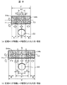
次に、図3は冷却器7の周辺部を冷蔵庫正面から見た図である。図4は、除霜ヒータ22の詳細図である。図5,図6は、除霜ヒータ22のA‐A断面図である。冷却器7の上部には除霜センサ41が設置されており、除霜センサ41で検出される温度によって除霜に関する判定を行っている。除霜センサ41は、冷却器7を下部から加熱する場合、通常、冷却器7上段側に設けることが一般的である。   Next, FIG. 3 is the figure which looked at the peripheral part of the cooler 7 from the refrigerator front. FIG. 4 is a detailed view of the defrost heater 22. 5 and 6 are AA cross-sectional views of the defrost heater 22. A defrost sensor 41 is installed in the upper part of the cooler 7, and a determination related to defrost is performed based on the temperature detected by the defrost sensor 41. When the cooler 7 is heated from the lower part, the defrost sensor 41 is generally provided on the upper stage side of the cooler 7.

除霜ヒータ22は、図5に示すように、電気ヒータ(図示省略)を内部に設けたガラス管44とガラス管44の外周に設けた金属フィン45(放熱フィン)から構成されるものや、図6に示すように、電気ヒータ線(図示省略)を内部に設けたガラス管44とその外周のガラス管59で構成される二重ガラス管の構造がある。これらは、可燃性冷媒を使用する冷蔵庫で採用されている除霜ヒータ22の一例あり、庫内で可燃性冷媒が漏れた場合を想定して、外側のガラス管表面温度を可燃性冷媒の発火点温度(イソブタンの場合494℃)よりも100℃程度低くする工夫がなされている。除霜ヒータ22には、ヒータ両端部に接続したコード57で電源を供給する。除霜時には除霜水が除霜ヒータ22の上部から滴下してくるので、ガラス管44,59の上部には、除霜水滴下防止部43を設けている。高温に加熱されたガラス管44,59に除霜水が直接滴下すると、急激な温度変化によりガラスが破損するおそれがあるためである。この現象を防止するために、除霜水滴下防止部43の幅Bは、少なくとも除霜ヒータ22の外径C以上にしている。また、冷却運転時の通風抵抗を考慮すると、概ね幅Bと直径Cは等しくすることが好ましい。可燃性冷媒を用いた除霜ヒータ22は、例えば金属フィン45の外径Cがφ28mm、ガラス管44の外径がφ10mmである。   As shown in FIG. 5, the defrost heater 22 includes a glass tube 44 provided with an electric heater (not shown) and a metal fin 45 (radiation fin) provided on the outer periphery of the glass tube 44, As shown in FIG. 6, there is a double glass tube structure including a glass tube 44 provided with an electric heater wire (not shown) and a glass tube 59 on the outer periphery thereof. These are examples of the defrosting heater 22 employed in a refrigerator that uses a flammable refrigerant. Assuming that the flammable refrigerant leaks in the refrigerator, the surface temperature of the outer glass tube is ignited by the flammable refrigerant. A contrivance has been made to make the temperature lower by about 100 ° C. than the point temperature (494 ° C. for isobutane). Power is supplied to the defrosting heater 22 by a cord 57 connected to both ends of the heater. Since defrost water is dripped from the upper part of the defrost heater 22 at the time of defrosting, the defrost water dripping prevention part 43 is provided in the upper part of the glass tubes 44 and 59. FIG. This is because if the defrost water is directly dropped onto the glass tubes 44 and 59 heated to a high temperature, the glass may be damaged due to a rapid temperature change. In order to prevent this phenomenon, the width B of the defrost water dripping preventing portion 43 is set to be at least the outer diameter C of the defrost heater 22 or more. In consideration of the ventilation resistance during the cooling operation, it is preferable that the width B and the diameter C are substantially equal. In the defrosting heater 22 using a flammable refrigerant, for example, the outer diameter C of the metal fin 45 is φ28 mm, and the outer diameter of the glass tube 44 is φ10 mm.

可燃性冷媒を採用している冷蔵庫の除霜ヒータ22は、ガラス管44の外周部に設けた金属フィン45又はガラス管59,除霜水滴下防止部43から構成される場合が一般的である。ヒータ線を内部に設けたガラス管44に近接して金属フィン45(又はガラス管59),除霜水滴下防止部43を設けているので、それぞれの表面温度は霜を解かすのに十分高く、ガラス管44,金属フィン45,ガラス管59、及び除霜水滴下防止部43を含めて発熱部(除霜ヒータ22)と定義できる。また、冷却器7の下部には除霜ヒータ22の過熱を防止する温度ヒューズ42を設けている。   In general, the defrosting heater 22 of the refrigerator that employs the flammable refrigerant is configured by the metal fin 45 or the glass tube 59 provided on the outer peripheral portion of the glass tube 44 and the defrosting water dripping preventing unit 43. . Since the metal fin 45 (or the glass tube 59) and the defrost water dripping prevention part 43 are provided in the vicinity of the glass tube 44 provided with the heater wire inside, the respective surface temperatures are sufficiently high to defrost. In addition, the glass tube 44, the metal fin 45, the glass tube 59, and the defrost water dripping prevention unit 43 can be defined as a heat generating unit (defrost heater 22). Further, a thermal fuse 42 for preventing the defrost heater 22 from being overheated is provided below the cooler 7.

冷蔵室2に送られた冷気を、野菜室6を経由せずに直接冷却器7に戻す場合は、図3に示すように、冷蔵室冷気戻り風路46が冷却器7の横に設けてあり、冷蔵室戻り冷気は冷却器7の横から流入する構造になっている。   When the cool air sent to the refrigerator compartment 2 is returned directly to the cooler 7 without going through the vegetable compartment 6, a refrigerator compartment cool air return air passage 46 is provided beside the cooler 7 as shown in FIG. Yes, the cold air returning from the refrigerator compartment flows from the side of the cooler 7.

次に、図7は除霜時の除霜センサ41で検出される温度(以下、「除霜センサ温度」と称する)と、除霜時の冷凍室温度の経時変化の一例である。除霜開始時(時刻t0)の除霜センサ温度をTD0とすると、除霜開始後から徐々に温度が上昇する。そして、霜が解けている間は相変化中であるため約0℃で推移する。霜が解け終わると除霜センサ温度は再び上昇して、予め決められている除霜終了温度TD1に到達した時点(時刻t1)で除霜ヒータ22の通電を止めて除霜が終了する。   Next, FIG. 7 is an example of the change over time of the temperature detected by the defrost sensor 41 during defrosting (hereinafter referred to as “defrost sensor temperature”) and the freezer compartment temperature during defrosting. If the defrost sensor temperature at the start of defrosting (time t0) is TD0, the temperature gradually increases after the start of defrosting. And while the frost is thawed, it changes at about 0 ° C. because the phase is changing. When the defrosting is finished, the defrosting sensor temperature rises again, and when the defrosting end temperature TD1 is reached (time t1), the defrosting heater 22 is deenergized and the defrosting is completed.

霜は冷却器7の下部から上部に向かって解けるので、除霜センサ41で検出される温度は、冷却器7の下部の温度経時変化とは異なり、冷却器7の下部の霜が先に解ける。そのため、約0℃を推移する時間帯は、冷却器7の下部で先に終了している。   Since the frost is melted from the lower part to the upper part of the cooler 7, the temperature detected by the defrost sensor 41 is different from the temperature aging of the lower part of the cooler 7, and the frost at the lower part of the cooler 7 is first melted. . Therefore, the time zone in which about 0 ° C. transitions ends first at the lower part of the cooler 7.

除霜中は冷凍温度帯室(製氷室3,上段冷凍室4,下段冷凍室5)の冷却を行っていないので、冷凍室温度はTF0(除霜開始時刻t0)からTF1(除霜終了時刻t1)に上昇する。例えば、着霜量が同じであっても除霜ヒータ22の加熱により生じる空気の上昇流によって除霜時間が変化することがある。除霜終了温度TD1に到達する時刻がt1からt2になった場合、除霜時間が長くなる(グラフの破線)ため除霜ヒータで消費される電力量が多くなり、除霜ヒータ22で加熱した分だけ庫内への熱負荷が増加することになる。これは、除霜終了後の再冷却時の電力量増加に影響することになる。また、冷凍温度帯室の温度がTF2まで上昇してしまうため、冷凍食品の保存性にも影響を及ぼすことになる。従って、除霜ヒータ22による庫内への熱負荷増加を抑制するために、少ないヒータ加熱量で除霜時間を短くすることが、省エネルギー性向上と冷凍食品の保存性向上に役立つことになる。   During defrosting, the freezing temperature zone (ice-making room 3, upper freezing room 4, lower freezing room 5) is not cooled, so the freezing room temperature is changed from TF0 (defrosting start time t0) to TF1 (defrosting end time). rise to t1). For example, even if the amount of frost formation is the same, the defrost time may change due to the upward flow of air generated by the heating of the defrost heater 22. When the time to reach the defrosting end temperature TD1 is changed from t1 to t2, the defrosting time becomes longer (broken line in the graph), so the amount of electric power consumed by the defrosting heater is increased and the defrosting heater 22 is heated. The heat load to the inside increases by the amount. This affects the increase in the amount of power during recooling after the completion of defrosting. Moreover, since the temperature of a freezing temperature zone room will rise to TF2, it will affect the preservability of frozen food. Therefore, shortening the defrosting time with a small heater heating amount in order to suppress an increase in the thermal load in the cabinet by the defrosting heater 22 is useful for improving energy saving and improving the storage stability of frozen foods.

次に、図8は冷却器7の周囲の断面図である。冷却器7は断熱箱体10の庫内側背面壁65と、冷却器カバー62とで前後が区画された冷却器収納室8に設置されている。冷却器カバー62の前面側には、冷凍温度帯室背面部材58を設けており、冷却器カバー62と冷凍温度室背面部材58との間には、下段冷凍室送風ダクト13(または上段冷凍室送風ダクト12)を形成している。冷却器7の前面側には、バイパス風路60,冷却器7の背面側にはバイパス風路61がそれぞれ設けている。これらのバイパス風路60,61は、冷却器7の下段部に多量の霜が成長した場合であっても、冷却性能が所定の時間、維持できるように設けたものである。バイパス風路60,61の形状は、冷却器7の形態や冷気風路に応じて決定される。バイパス風路60,61を設けない場合は、冷却器カバー62と冷却器7,庫内側背面壁65と冷却器7の間に、隙間はほとんど形成されない。   Next, FIG. 8 is a sectional view around the cooler 7. The cooler 7 is installed in a cooler storage chamber 8 whose front and rear sections are partitioned by an inner back wall 65 of the heat insulation box 10 and a cooler cover 62. A freezing temperature zone back member 58 is provided on the front side of the cooler cover 62, and the lower freezer compartment air duct 13 (or the upper freezer compartment) is provided between the cooler cover 62 and the freezing temperature compartment back member 58. An air duct 12) is formed. A bypass air path 60 is provided on the front side of the cooler 7, and a bypass air path 61 is provided on the back side of the cooler 7. These bypass air passages 60 and 61 are provided so that the cooling performance can be maintained for a predetermined time even when a large amount of frost grows in the lower part of the cooler 7. The shape of the bypass air passages 60 and 61 is determined according to the form of the cooler 7 and the cold air air passage. When the bypass air passages 60 and 61 are not provided, almost no gap is formed between the cooler cover 62 and the cooler 7, and the inner back wall 65 and the cooler 7.

除霜開始直後においては、除霜ヒータ22で加熱された空気が冷却器7の最下段に成長した霜の通風抵抗により、冷凍温度帯室冷気戻り口17の方向へ流れが発生する可能性がある。冷却器カバー62と冷凍温度帯室背面部材58との間には、下方が開口した加熱空気流入空間64を設けてある。すなわち、下段冷凍室5と冷却器収納室61との間に、下方が開口して前記発熱部で加熱された空気が流入する空間を有する。これにより、除霜ヒータ22で加熱された空気は、一旦、加熱空気流入空間64に導入することができるので、冷凍温度帯室への熱負荷流入を最小限に防ぐことができる。   Immediately after the start of the defrosting, there is a possibility that the air heated by the defrosting heater 22 may flow in the direction of the refrigeration temperature chamber cold air return port 17 due to the draft resistance of the frost that has grown in the lowermost stage of the cooler 7. is there. Between the cooler cover 62 and the refrigeration temperature zone chamber back member 58, a heated air inflow space 64 opened downward is provided. That is, there is a space between the lower freezing chamber 5 and the cooler housing chamber 61 where the lower portion opens and the air heated by the heat generating portion flows in. Thereby, since the air heated with the defrost heater 22 can once be introduce | transduced into the heating air inflow space 64, the heat load inflow to a freezing temperature zone room can be prevented to the minimum.

以上のように、除霜ヒータ22で加熱された空気の流れは、霜や冷却器を通過する際の通風抵抗に大きく影響されることが分かる。特に除霜ヒータ22よりも高い位置に冷凍温度帯室冷気戻り口17を設け、可燃性冷媒を使用するために除霜ヒータ22の表面温度の上限に制限がある冷蔵庫では、その流れが除霜効率に大きく影響する。   As mentioned above, it turns out that the flow of the air heated with the defrost heater 22 is greatly influenced by the ventilation resistance at the time of passing a frost and a cooler. In particular, in a refrigerator in which the refrigeration temperature chamber cold air return port 17 is provided at a position higher than the defrost heater 22 and the upper limit of the surface temperature of the defrost heater 22 is limited in order to use a flammable refrigerant, the flow is defrosted. Greatly affects efficiency.

次に、除霜ヒータ22と加熱された空気の流れについて説明する。図8から図15では、前後に隣接する冷却器パイプ54a,54bの外表面間の水平方向の距離をA1、冷却器カバー62と冷却器カバー62側に対向する冷却器パイプ54aの外表面との水平方向の距離をA2、対向する冷却器パイプ54bの外表面と庫内側背面壁65の水平方向の距離をA3、除霜ヒータ22の直径をCとする。また、霜は破線で表した領域にそれぞれ成長しているものとする。   Next, the flow of the defrost heater 22 and the heated air will be described. 8 to 15, the horizontal distance between the outer surfaces of the cooler pipes 54a and 54b adjacent to each other in front and rear is A1, and the outer surface of the cooler pipe 54a facing the cooler cover 62 and the cooler cover 62 side. The horizontal distance is A2, the horizontal distance between the outer surface of the opposing cooler pipe 54b and the inner back wall 65 is A3, and the diameter of the defrost heater 22 is C. In addition, it is assumed that frost grows in each area represented by a broken line.

まず、霜が成長する段階について説明する。図9は本発明の実施例で、隣接する冷却器パイプ54a,54bの外表面間の水平距離A1が除霜ヒータ22の直径Cよりも大きい場合の冷却時の着霜について示した模式図である。図9(a)は、距離A1が除霜ヒータ22の直径Cよりも小さい場合であって、図9(b)は、距離A1が除霜ヒータ22の直径Cよりも大きい場合であり、冷却器7の最下段部における着霜の様子を示す。冷却器7は最下段部の着霜が最も多く、着霜の仕方が除霜時間に大きく影響するので、最下段部の着霜に着目する。   First, the stage where frost grows will be described. FIG. 9 is an embodiment of the present invention, and is a schematic diagram showing frost formation during cooling when the horizontal distance A1 between the outer surfaces of the adjacent cooler pipes 54a and 54b is larger than the diameter C of the defrost heater 22. is there. FIG. 9A shows a case where the distance A1 is smaller than the diameter C of the defrost heater 22, and FIG. 9B shows a case where the distance A1 is larger than the diameter C of the defrost heater 22. The mode of frost formation in the lowest step part of the vessel 7 is shown. The cooler 7 has the most frost formation at the lowermost step, and the manner of frosting greatly affects the defrosting time, so attention is paid to the frost formation at the lowermost step.

冷却器7のフィン横幅をF、冷媒パイプ54a,54bの周囲に成長する霜の高さをLf1、冷媒パイプ54a,54bの外表面との水平方向の距離をD、冷媒パイプ54a,54bの外表面とフィン端部までの水平方向の距離をE、フィンピッチをPfとする。   The fin width of the cooler 7 is F, the height of frost growing around the refrigerant pipes 54a and 54b is Lf1, the horizontal distance from the outer surfaces of the refrigerant pipes 54a and 54b is D, and the outside of the refrigerant pipes 54a and 54b. The horizontal distance from the surface to the fin end is E, and the fin pitch is Pf.

図9(a),(b)共に、冷却器7の最下段には、冷却器7の最下段の下側と前側(図9の左側)から冷気が戻ってくるため、フィンの前縁部の霜71が多くなる傾向がある。
冷媒パイプ54a,54bの表面は、最も温度が低くなっているが、フィン前縁部に流入した戻り冷気の水分は霜になるため除湿され、冷媒パイプ54a,54b周囲の霜70は、フィン前縁部の霜の高さと同じか、又はそれ以下の高さとなる。冷媒パイプ54a,54bの周囲に成長する霜70は、戻り冷気が進入する側に多くの霜が成長する傾向がある。フィンピッチPfを5mmにした場合、冷蔵庫1ではフィン間が閉塞する前に除霜が行われるので、冷媒パイプ54a,54b周囲に成長する霜の高さLf1は高くても2.5mm以下である。
9 (a) and 9 (b), the cool air returns to the lowermost stage of the cooler 7 from the lower side and the front side (left side of FIG. 9) of the lowermost stage of the cooler 7, so that the front edge of the fin The frost 71 tends to increase.
The surface of the refrigerant pipes 54a and 54b has the lowest temperature, but the moisture of the return cold air flowing into the front edge of the fin is defrosted and dehumidified, and the frost 70 around the refrigerant pipes 54a and 54b The height is the same as or lower than the frost height at the edge. The frost 70 that grows around the refrigerant pipes 54a and 54b tends to grow a lot on the side where the return cold air enters. When the fin pitch Pf is 5 mm, defrosting is performed before the gap between the fins is closed in the refrigerator 1, so that the height Lf1 of the frost growing around the refrigerant pipes 54a and 54b is 2.5 mm or less at the highest. .

例えば、図9(a)に示す距離A1が除霜ヒータ22の直径Cよりも小さい場合、フィン幅F=60mm、A1=16.6mm、C=28mm、E=13.3mm、Lf1=2.5mmとして、冷媒パイプ54a,54bの周囲に成長した霜の外表面間の水平距離をGとすると、G=11.6mmとなる。従って、着霜量が冷媒パイプ54a,54b周囲よりも少ない場所となる水平方向の距離Gは、除霜ヒータ22の直径Cよりも小さくなり、着霜70によって除霜時に加熱されて生じる上昇流の妨げになり易い。   For example, when the distance A1 shown in FIG. 9A is smaller than the diameter C of the defrosting heater 22, the fin width F = 60 mm, A1 = 16.6 mm, C = 28 mm, E = 13.3 mm, Lf1 = 2. If the horizontal distance between the outer surfaces of the frost that has grown around the refrigerant pipes 54a and 54b is G, G = 11.6 mm. Accordingly, the horizontal distance G where the amount of frost formation is smaller than that around the refrigerant pipes 54 a and 54 b is smaller than the diameter C of the defrost heater 22, and the upward flow generated by heating by the frost 70 during defrosting. It is easy to disturb.

一方、図9(b)示す距離A1が除霜ヒータ22の直径Cよりも大きい場合、フィン幅F=77mm、A1=41.6mm、C=28mm、E=9.3mm、Lf1=2.5mmとして、冷媒パイプ54a,54bの周囲に成長した霜の外表面間の距離をGとすると、G=36.6mmとなる。この場合、冷媒パイプ54aと対向する除霜ヒータ22との水平距離Dは6.8mmとなり、冷媒パイプ54a,54b周囲に成長する霜の高さLf1が3mmになったとしても、冷媒パイプ54a,54b周囲に成長する霜の先端が除霜ヒータ22に到達することはない。従って、冷媒パイプ54a,54b周囲よりも相対的に着霜量が少ない場所となる水平距離Gは、除霜ヒータ22の直径Cよりも大きくなり、除霜時に加熱されて生じる上昇流を促進し易くなる。   On the other hand, when the distance A1 shown in FIG. 9B is larger than the diameter C of the defrosting heater 22, the fin width F = 77 mm, A1 = 41.6 mm, C = 28 mm, E = 9.3 mm, Lf1 = 2.5 mm. Assuming that the distance between the outer surfaces of the frost grown around the refrigerant pipes 54a and 54b is G, G = 36.6 mm. In this case, the horizontal distance D between the refrigerant pipe 54a and the defrosting heater 22 facing the refrigerant pipe 54a is 6.8 mm, and even if the height Lf1 of the frost growing around the refrigerant pipes 54a and 54b is 3 mm, The tip of the frost that grows around 54b does not reach the defrost heater 22. Therefore, the horizontal distance G where the amount of frost formation is relatively smaller than the surroundings of the refrigerant pipes 54a and 54b is larger than the diameter C of the defrost heater 22, and promotes the upward flow generated by heating during defrosting. It becomes easy.

フィン前縁部は熱伝達が促進されるので霜が成長し易く、通風抵抗になり易いが、水平距離A1を長くすることにより水平距離Gも長くなり、水平距離G部分を通過する風速Uを遅くすることができるので、隣接する冷媒パイプ54a,54bの外表面間の水平距離A1を長くすることで、冷却器全体の通風抵抗の低減に寄与する。   Since heat transfer is promoted at the front edge of the fin, frost is likely to grow, and air resistance is likely to occur.However, by increasing the horizontal distance A1, the horizontal distance G is also increased, and the wind speed U passing through the horizontal distance G portion is increased. Since it can be slowed down, increasing the horizontal distance A1 between the outer surfaces of the adjacent refrigerant pipes 54a and 54b contributes to a reduction in the ventilation resistance of the entire cooler.

次に、図10はフィンの板厚さを変えた場合の、着霜時の様子を模式的に示したものである。一般的に、冷媒パイプ54a,54bのパイプ間ピッチを大きくすると(隣接する冷媒パイプ54a,54bの外表面間の水平距離A1を長くすることと同等)、その間のフィン効率が低下するため、冷却器全体の性能が低下する。従って、図10(a)に示す従来フィン厚さ72の場合、水平距離A1を長くすると、冷媒パイプ間のフィン効率が低下する。そのため、冷媒パイプ54a,54bの中心に向かうに従い、フィン表面に成長する霜Lf2の高さが低くなる。これは、フィン効率低下に伴う冷却性能の低下のためである。一方、図10(b)に示す従来よりもフィンを厚くしたフィン厚さ73の場合、冷媒パイプ54a,54b間のフィン効率を高めることができるので、冷却性能が高くなり、その結果としてフィン表面に成長する霜Lf2の高さが高くなることが分かる。   Next, FIG. 10 schematically shows a state of frost formation when the plate thickness of the fin is changed. Generally, when the pitch between the refrigerant pipes 54a and 54b is increased (equivalent to increasing the horizontal distance A1 between the outer surfaces of the adjacent refrigerant pipes 54a and 54b), the fin efficiency between them decreases, so that cooling is performed. The overall performance of the vessel is reduced. Therefore, in the case of the conventional fin thickness 72 shown in FIG. 10A, if the horizontal distance A1 is increased, the fin efficiency between the refrigerant pipes is lowered. Therefore, the height of the frost Lf2 that grows on the fin surface decreases toward the center of the refrigerant pipes 54a and 54b. This is due to a decrease in cooling performance accompanying a decrease in fin efficiency. On the other hand, in the case of fin thickness 73 in which the fins are thicker than the conventional one shown in FIG. 10 (b), the fin efficiency between the refrigerant pipes 54a and 54b can be increased. It can be seen that the height of the frost Lf2 that grows rapidly increases.

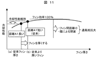
以上の現象について、図11でさらに説明する。図11はフィン厚さと冷却性能の関係を表したものである。庫内ファン9の回転数を一定とした場合、フィン厚さを厚くするとフィン効率が高くなるので、冷却性能が高くなる。また、距離A1を従来よりも長くすると冷媒パイプ間のフィン効率が低下するので、それを補うためにフィンを厚くした方がよい。フィン厚さに関しては、フィン効率が100%となるフィン厚さが存在し、それ以上フィンを厚くしても、冷却性能を向上させることはできない。必要以上にフィンを厚くすると、フィン間距離が小さくなり、また霜による閉塞の影響により冷却性能は悪化してしまう。   The above phenomenon will be further described with reference to FIG. FIG. 11 shows the relationship between fin thickness and cooling performance. When the number of rotations of the internal fan 9 is constant, the fin efficiency increases when the fin thickness is increased, so that the cooling performance increases. Moreover, since fin efficiency between refrigerant pipes will fall if distance A1 is made longer than before, it is better to thicken the fins to compensate for this. Regarding the fin thickness, there is a fin thickness at which the fin efficiency becomes 100%, and even if the fin is thickened further, the cooling performance cannot be improved. If the fins are made thicker than necessary, the distance between the fins becomes small, and the cooling performance deteriorates due to the influence of blockage due to frost.

以上をまとめると、隣接する冷媒パイプ54a,54bの外表面間の水平距離A1を除霜ヒータ22の直径Cよりも大きくすることにより、冷媒パイプ54a,54bの周囲よりも着霜量が少ない場所に除霜ヒータ22の直径Cが位置するように配置できる。除霜時には除霜ヒータ22の直径Cの真上を加熱された空気が上昇するので、除霜現象が促進されて、除霜時間の短縮につながる。   In summary, the horizontal distance A1 between the outer surfaces of the adjacent refrigerant pipes 54a and 54b is made larger than the diameter C of the defrost heater 22 so that the amount of frost formation is smaller than that around the refrigerant pipes 54a and 54b. It can arrange | position so that the diameter C of the defrost heater 22 may be located. At the time of defrosting, the heated air rises just above the diameter C of the defrosting heater 22, so that the defrosting phenomenon is promoted and the defrosting time is shortened.

次に、霜が解ける段階について説明する。図12は、隣接する冷媒パイプ54a,54bの外表面間の水平距離A1が除霜ヒータ22の直径Cよりも大きい場合の、霜の解け方について模式的に示したものである。図12では、冷却器7の全体の除霜の様子を説明するため、図9で示した冷媒パイプ周囲の霜は省略しているが、着霜分布に関しては図9に従う。冷媒パイプ54a,54bにフィンを固定する際には、フィンカラーを設ける場合が多く、その部分は冷却器パイプの外径よりもフィン厚さ分だけ厚くなるが、その厚さは水平距離A1よりも十分小さいため、フィンカラー部については考慮しないこととする。   
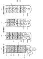
Next, the stage where frost can be dissolved will be described. FIG. 12 schematically shows how to defrost frost when the horizontal distance A1 between the outer surfaces of the adjacent refrigerant pipes 54a and 54b is larger than the diameter C of the defrost heater 22. In FIG. 12, the frost around the refrigerant pipe shown in FIG. 9 is omitted in order to explain the overall defrosting of the cooler 7, but the frost distribution follows FIG. When fixing fins to the refrigerant pipes 54a and 54b, a fin collar is often provided, and the portion is thicker by the fin thickness than the outer diameter of the cooler pipe, but the thickness is larger than the horizontal distance A1. Is sufficiently small, the fin collar portion is not considered.

なお、上昇流55の流れと霜の解け方を中心に説明するため、冷却器7の周辺の構造は簡略化しているが、冷却器7は図8に示した部分に設けてある。図12(a)は、除霜開始(時刻t0)、図12(d)は除霜終了(時刻t1)で、図12(b),(c)はその間の除霜過程を模式的に示してある。   The structure around the cooler 7 is simplified in order to explain mainly the flow of the rising flow 55 and the way of melting frost, but the cooler 7 is provided in the portion shown in FIG. Fig. 12 (a) shows the start of defrosting (time t0), Fig. 12 (d) shows the end of defrosting (time t1), and Figs. 12 (b) and 12 (c) schematically show the defrosting process during that time. It is.

冷却器7に成長する霜52は、冷凍温度帯室冷気戻り口17側に近い冷却器7の最下段に多く成長し、冷却器7のフィン前縁部に多く霜が成長する。図12(a)の除霜開始では、除霜ヒータ22により周囲の空気が加熱されて、冷却器7の最下段に向かう上昇流55が発生する。この上昇流55は、除霜ヒータ22の真上、すなわち水平距離C(除霜ヒータの直径C)の真上が最も強く発生する。上昇流55によって徐々に霜が加熱されて解け始めるが、除霜初期段階で、冷却器7の最下段に成長した霜が多い場合は、上昇流55が冷凍温度帯室冷気戻り口17側に流出する流れ56(図8参照)が発生する場合もあり、加熱空気流入空間64により直接冷凍温度帯室に流出し難くしてある。   The frost 52 that grows on the cooler 7 grows more on the lowermost stage of the cooler 7 near the refrigeration temperature chamber cold air return port 17 side, and more frost grows on the fin front edge of the cooler 7. At the start of the defrosting in FIG. 12A, the ambient air is heated by the defrosting heater 22, and an upward flow 55 toward the lowermost stage of the cooler 7 is generated. This upward flow 55 is most strongly generated immediately above the defrost heater 22, that is, directly above the horizontal distance C (the diameter C of the defrost heater). Although the frost is gradually heated by the upflow 55 and begins to melt, at the initial stage of defrosting, when there is a lot of frost that has grown in the lowermost stage of the cooler 7, the upflow 55 is directed to the freezing temperature zone cold air return port 17 side. An outflowing flow 56 (see FIG. 8) may be generated, and the heated air inflow space 64 makes it difficult for the outflow to flow directly into the freezing temperature zone chamber.

冷却器7の最下段の霜が解けるに従い、水平距離A1が除霜ヒータ22の直径Cよりも大きいため、除霜ヒータ22の真上の霜は解け易くなり、図12(b)のように、除霜促進部66が見られるようになる。これは、除霜ヒータ22の上に形成される上昇流55は、水平距離A1が除霜ヒータ22の直径Cよりも大きくしているため、上昇流55が冷媒パイプ54a,54bからの通風抵抗を受け難くなり、水平距離A1部の霜の融解促進が行われることによる。   As the frost at the lowermost stage of the cooler 7 is melted, the horizontal distance A1 is larger than the diameter C of the defrost heater 22, so that the frost just above the defrost heater 22 is easily melted, as shown in FIG. The defrost promotion part 66 comes to be seen. This is because the upward flow 55 formed on the defrosting heater 22 has a horizontal distance A1 larger than the diameter C of the defrosting heater 22, and therefore the upward flow 55 is resisted by ventilation from the refrigerant pipes 54a and 54b. This is because the frost melting at the horizontal distance A1 is accelerated.

また、図9に示すように、除霜ヒータ22の直径Cが設置されている真上の各段のフィン部分の霜は相対的に少なくなっているので、除霜過程において水平距離A1部を上昇流55が流れ易くなり、冷却器7の最下段部から最上段部に向かって流れが積極的に生じ、冷却器7の各段のフィンに熱が伝わり易くなって(図12(b)の矢印で示す伝熱経路67)、霜が素早く解ける。除霜センサ41の設置場所は、強い上昇流55が発生し易くなる、水平距離A1以外(前後に位置する冷媒パイプの間よりも外側)の場所で冷却器7の上方がよい。   Moreover, as shown in FIG. 9, since the frost of the fin part of each step | level just above the diameter C of the defrost heater 22 has relatively decreased, horizontal distance A1 part is reduced in a defrost process. Ascending flow 55 becomes easy to flow, a flow is actively generated from the lowermost step portion of the cooler 7 toward the uppermost step portion, and heat is easily transferred to the fins of each step of the cooler 7 (FIG. 12B). The heat transfer path 67) indicated by the arrow in FIG. The defrost sensor 41 is preferably installed above the cooler 7 at a place other than the horizontal distance A1 (outside from between the refrigerant pipes located at the front and rear) where the strong upward flow 55 is likely to be generated.

次に、図13は冷却器7と冷凍温度帯室(上段冷凍室4,下段冷凍室5)の近傍の断面図である。図9では、除霜過程について冷却器を中心に模式的に説明したが、ここでは、除霜時に発生する空気の上昇流55の冷凍温度帯室内を含めた経路について説明する。除霜ヒータ22の加熱によって生じた上昇流55は、水平距離A1が除霜ヒータ22の直径Cよりも大きくしてあるので、水平距離A1部を流れ易くなる。   Next, FIG. 13 is a cross-sectional view of the vicinity of the cooler 7 and the freezing temperature zone (upper freezing chamber 4, lower freezing chamber 5). In FIG. 9, the defrosting process is schematically described focusing on the cooler, but here, a path including the freezing temperature zone of the upward flow 55 of the air generated during the defrosting will be described. Since the horizontal distance A1 is larger than the diameter C of the defrost heater 22, the upward flow 55 generated by the heating of the defrost heater 22 easily flows through the horizontal distance A1.

上昇流55が冷却器7の最上段を通過した後、庫内ファン9,冷凍室ダンパ50を通過し、主に冷凍室吐出口51aから上段冷凍室4に流出する。冷凍室ダンパ50を備えた冷蔵庫では、上昇流55が冷凍室吐出口51aから上段冷凍室4に流出するように、冷凍室ダンパ50を開にする方がよい。冷凍室ダンパ50を閉状態にすると上昇流55が発生し難くなるため、冷凍温度帯室冷気戻り口17からの加熱空気の流出や、除霜時間の延長により必要以上に冷却器7の下段部の加熱が行われることになる。上段冷凍室4に流出した上昇流55は、その後、上段冷凍室4,下段冷凍室5によって冷却されるので、下降流63となって上段冷凍室4,下段冷凍室5を降下し、再び冷凍温度帯室冷気戻り口17から冷却器収納室8に流入する。   After the upward flow 55 passes through the uppermost stage of the cooler 7, it passes through the internal fan 9 and the freezer damper 50 and flows out mainly from the freezer outlet 51 a to the upper freezer 4. In the refrigerator equipped with the freezer compartment damper 50, it is better to open the freezer compartment damper 50 so that the upward flow 55 flows out from the freezer outlet 51a to the upper freezer compartment 4. When the freezer compartment damper 50 is closed, it is difficult for the upward flow 55 to be generated. Will be heated. The upward flow 55 flowing out into the upper freezer compartment 4 is then cooled by the upper freezer compartment 4 and the lower freezer compartment 5, so that it becomes a downward flow 63 and descends the upper freezer compartment 4 and the lower freezer compartment 5 to freeze again. It flows into the cooler housing chamber 8 from the temperature zone chamber cold air return port 17.

このように、冷却器7を下から上に向う上昇流55と、上段冷凍室4,下段冷凍室5を上から下に向う下降流63によって循環流が形成される。   In this manner, a circulating flow is formed by the upward flow 55 that goes from the bottom to the top of the cooler 7 and the downward flow 63 that goes from the top to the bottom of the upper freezing chamber 4 and the lower freezing chamber 5.

強い上昇流55が発生すると、除霜ヒータ22の熱が速く冷却器7の上部まで伝わる(図12(b)の伝熱経路67)ので霜が解け易くなる。同時に下降流63も強くなるので、下降流63と逆向きの冷凍温度帯室冷気戻り口17から下段冷凍室5に流出する加熱空気56の流れは抑制される。   When the strong upward flow 55 is generated, the heat of the defrost heater 22 is quickly transmitted to the upper part of the cooler 7 (heat transfer path 67 in FIG. 12B), so that the frost can be easily dissolved. At the same time, the downflow 63 also becomes strong, so that the flow of the heated air 56 flowing out from the freezing temperature zone cold air return port 17 opposite to the downflow 63 into the lower freezing chamber 5 is suppressed.

以上のように冷媒パイプ4a,54bは発熱部(除霜ヒータ22)の上方投影面よりも前方及び後方にそれぞれ位置するように間隔をあけて配置しているので、除霜ヒータ22の直径Cの範囲の強い上昇流55が距離A1部を通過することにより、引き起こす循環流で除霜時間を短縮することができ、省エネルギー化を図ることができる。   As described above, the refrigerant pipes 4a and 54b are arranged at intervals so as to be positioned forward and rearward from the upper projection surface of the heat generating portion (defrost heater 22). By passing the upward flow 55 having a strong range of 1 through the distance A1, the defrosting time can be shortened by the circulating flow caused, and energy saving can be achieved.

次に図14は、本発明に係る他の実施例である。図14(a)は除霜開始(時刻t0)、図14(b)は除霜過程を模式的に示したものである。冷却器カバー62に対向する冷媒パイプ54aの外表面と冷却器カバー62の水平距離A2、除霜ヒータ22の直径Cとする。水平距離A2を除霜ヒータ22の直径Cよりも大きくすることで、冷却時には冷却器54aのパイプ周囲に霜が成長し易いが、水平距離A2を大きくしているため、フィン前側(冷凍室側)に成長する霜を抑えることができる。従って、除霜時には水平距離A2を上昇流55が、冷却器7の最下段部から最上段部へと流れ易くなる。図14(b)に示すように、冷却器7に成長した霜52は徐々に解けて、水平距離A2部に除霜促進部66が現れる。これにより、除霜促進部66は徐々に冷却器7の最上部に進み、上昇流55と、冷凍室4,5内に発生する下降流63によって循環流が形成され、冷却器7の各段の霜の融解が促進される。除霜センサ41の設置場所は、強い上昇流55が発生し易い、水平距離A2以外の場所で、冷却器7の上方がよい。   Next, FIG. 14 shows another embodiment according to the present invention. FIG. 14A schematically shows the defrosting process (time t0), and FIG. 14B schematically shows the defrosting process. A horizontal distance A2 between the outer surface of the refrigerant pipe 54 a facing the cooler cover 62 and the cooler cover 62, and a diameter C of the defrost heater 22. By making the horizontal distance A2 larger than the diameter C of the defrost heater 22, frost tends to grow around the pipe of the cooler 54a during cooling, but since the horizontal distance A2 is increased, the fin front side (freezer compartment side) ) To grow frost. Accordingly, during the defrosting, the upward flow 55 easily flows from the lowermost step portion of the cooler 7 to the uppermost step portion through the horizontal distance A2. As shown in FIG. 14B, the frost 52 that has grown on the cooler 7 is gradually melted, and a defrost promoting portion 66 appears at the horizontal distance A2 portion. Thereby, the defrost promotion part 66 gradually proceeds to the uppermost part of the cooler 7, and a circulation flow is formed by the upward flow 55 and the downward flow 63 generated in the freezer compartments 4, 5. Frost melting is promoted. The installation place of the defrost sensor 41 is a place other than the horizontal distance A2 where a strong upward flow 55 is likely to be generated, and is preferably above the cooler 7.

次に図15は、本発明に係る他の実施例である。図15(a)は除霜開始(時刻t0)、図15(b)は除霜過程を模式的に示したものである。庫内側背面壁65に対向する冷媒パイプ54bの外表面と庫内側背面壁65の水平距離A3、除霜ヒータ22の直径Cとすると、水平距離A3を除霜ヒータ22の直径Cよりも大きくする。これにより、冷却時には冷却器54bのパイプ周囲に霜が成長し易いが、水平距離A3を大きくしているため、フィン後側(背面側)に成長する霜を抑えることができる。従って、除霜時には水平距離A3を上昇流55が、冷却器7の最下段部から最上段部へと流れ易くなる。図15(b)に示すように、冷却器7に成長した霜52は徐々に解けて、水平距離A3部に除霜促進部66が現れるようになる。   Next, FIG. 15 shows another embodiment according to the present invention. FIG. 15 (a) schematically shows the defrosting process (time t0), and FIG. 15 (b) schematically shows the defrosting process. If the horizontal distance A3 between the outer surface of the refrigerant pipe 54b facing the inner back wall 65 and the inner rear wall 65 and the diameter C of the defrost heater 22 are set, the horizontal distance A3 is made larger than the diameter C of the defrost heater 22. . Thereby, frost easily grows around the pipe of the cooler 54b during cooling, but since the horizontal distance A3 is increased, frost growing on the fin rear side (back side) can be suppressed. Accordingly, during the defrosting, the upward flow 55 easily flows from the lowermost step portion of the cooler 7 to the uppermost step portion through the horizontal distance A3. As shown in FIG. 15B, the frost 52 grown on the cooler 7 is gradually melted, and the defrost promoting part 66 appears at the horizontal distance A3.

これにより、除霜促進部66は徐々に冷却器7の最上部に進み、上昇流55と、冷凍室4,5内に発生する下降流63によって循環流が形成され、冷却器7の各段の霜の融解が進行し易くなる。この場合も同様に、除霜センサ41の設置場所は、強い上昇流55が発生し易くなる水平距離A3以外の場所で冷却器7の上方がよい。   Thereby, the defrost promotion part 66 gradually proceeds to the uppermost part of the cooler 7, and a circulation flow is formed by the upward flow 55 and the downward flow 63 generated in the freezer compartments 4, 5. The frost melts easily. Similarly, in this case, the defrost sensor 41 is preferably installed at a location other than the horizontal distance A3 where the strong upward flow 55 is likely to be generated and above the cooler 7.

次に図16は、本発明の実施形態に関する他の除霜方式の除霜センサ温度の経時変化の説明図である。Fダンパ50,Rダンパ20を備えた冷蔵庫では、冷却器7に成長した霜を解かすだけでなく、同時に霜(主に霜の潜熱)によって冷蔵室2や野菜室6を冷やすことができる。除霜開始(時刻t0、除霜センサ温度TD0)から除霜センサ温度がTDA(例えばTDAは3℃、時刻tA)になるまでの除霜を区間A、除霜センサ温度TDAからTD1(時刻t1)に到達するまでの除霜を区間Bとした、区間Aと区間Bを組み合せた除霜となる。Fダンパ50を設けていない冷蔵庫では、除霜ヒータ22のみによる区間Bの除霜となる。   Next, FIG. 16 is explanatory drawing of the time-dependent change of the defrost sensor temperature of the other defrost system regarding embodiment of this invention. In the refrigerator provided with the F damper 50 and the R damper 20, not only the frost that has grown on the cooler 7 can be released, but at the same time, the refrigerator compartment 2 and the vegetable compartment 6 can be cooled by frost (mainly frost latent heat). Defrosting from the start of defrosting (time t0, defrosting sensor temperature TD0) until the defrosting sensor temperature reaches TDA (for example, TDA is 3 ° C., time tA) is section A, and from defrosting sensor temperature TDA to TD1 (time t1) ) Is defrosting that combines section A and section B. In the refrigerator not provided with the F damper 50, the defrosting of the section B is performed only by the defrosting heater 22.

図17は、本発明に関する他の除霜方式の制御である。圧縮機の運転時間や外気温度の条件を満たした場合、除霜運転がスタートし(S1)、図16の区間Aの除霜が実施される(S2)。区間Aでは、庫内ファン9,除霜ヒータ22がONとなり、Rダンパ20が開、Fダンパ50が閉となる。除霜ヒータ22で加熱された空気は、冷却器7を通過する際に霜の冷熱エネルギーによって冷やされて冷蔵室(冷蔵温度帯の野菜室含む)にその冷気が供給され、同時に霜の融解が進行する。除霜ヒータ22の通電量は、庫内ファン9を運転しているため、冷蔵室2、あるいは野菜室6の庫内熱負荷を利用した分だけ、除霜ヒータ22だけで行う除霜よりも省エネルギー化を図ることができる。区間Aの除霜は、除霜センサ温度がTDAになるまで実施され(S3)、除霜センサ温度がTDA(時刻tA)以上になると区間Bの除霜(S4)に切り替わる。   FIG. 17 shows another defrosting system control relating to the present invention. When the conditions of the compressor operating time and the outside air temperature are satisfied, the defrosting operation is started (S1), and the defrosting in the section A of FIG. 16 is performed (S2). In the section A, the internal fan 9 and the defrost heater 22 are turned on, the R damper 20 is opened, and the F damper 50 is closed. When the air heated by the defrost heater 22 passes through the cooler 7, it is cooled by the cold energy of the frost, and the cold air is supplied to the refrigerator compartment (including the vegetable compartment in the refrigerator temperature zone). proceed. Since the energization amount of the defrost heater 22 is operating the internal fan 9, the defrost heater 22 alone or the vegetable room 6 uses the internal heat load of the refrigerator compartment 2 or the defrost heater 22 alone. Energy saving can be achieved. The defrosting in the section A is performed until the defrosting sensor temperature reaches the TDA (S3), and when the defrosting sensor temperature becomes equal to or higher than the TDA (time tA), the defrosting is switched to the defrosting in the section B (S4).

区間Bでは、庫内ファン9はOFF、除霜ヒータ22はON、Rダンパ20は閉、Fダンパ50は開となる。区間Bは除霜ヒータ22だけを用いた従来の除霜方式であり、除霜センサ温度がTD1になるまで除霜ヒータ22で加熱し(S5)、除霜ヒータ温度がTD1に到達した時点(時刻t1)で除霜が終了する(S6)。霜の潜熱を利用した冷却を行いながら除霜するため、除霜センサ温度TDAは少なくとも0℃以上が望ましい。除霜センサ温度がTDA以上で実施される区間Bでは、霜がほとんど残っていない場合が多いが、区間Bでは信頼性のため除霜センサ温度がTD1になるまで冷却器7を加熱している。   In section B, the internal fan 9 is OFF, the defrost heater 22 is ON, the R damper 20 is closed, and the F damper 50 is open. Section B is a conventional defrosting method using only the defrosting heater 22 and is heated by the defrosting heater 22 until the defrosting sensor temperature reaches TD1 (S5), and when the defrosting heater temperature reaches TD1 ( Defrosting ends at time t1) (S6). In order to perform defrosting while performing cooling using the latent heat of frost, the defrost sensor temperature TDA is desirably at least 0 ° C. or higher. In section B where the defrost sensor temperature is TDA or higher, there is often no frost remaining, but in section B, the cooler 7 is heated until the defrost sensor temperature reaches TD1 for reliability. .

区間Aでは庫内ファン9を運転しているため、冷却器7を通過する空気は強制対流となるが、区間Bでは従来通り除霜ヒータ22による上昇流55の作用によって冷却器7の最下段部から最上段部へ熱を伝えることになる。   Since the internal fan 9 is operated in the section A, the air passing through the cooler 7 is forced convection, but in the section B, the lowermost stage of the cooler 7 is operated by the action of the upward flow 55 by the defrost heater 22 as usual. Heat is transferred from the section to the top stage.

前述のように、冷却器7を通過する上昇流55,上段冷凍室4,下段冷凍室5を下降する下降流63からなる循環流の強さが除霜終了時間に影響する。従って、Fダンパ50を備えた冷蔵庫では、区間BにおいてFダンパ50を開にして循環流を形成し易くした方が良い。Rダンパ20,冷蔵室吐出口2c,冷蔵室戻りダクト46を通過して冷却器7に戻る風路は、冷凍室を中心とする上昇流55と下降流63からなる循環経路よりも風路が長くなるため通風抵抗が大きく、Rダンパ20を開にして冷蔵室に循環流を発生させることは困難である。従って、除霜終了時間はFダンパ50の開閉に影響する。区間Bの除霜ヒータ22による除霜時には、Fダンパ50は開にした方が除霜時間は早く終了し(図16の実線)、Fダンパ50を閉にすると循環流が形成されないため、除霜時間は長くなる(図16の破線)。   As described above, the strength of the circulating flow composed of the upward flow 55 passing through the cooler 7, the downward flow 63 descending the upper freezing chamber 4 and the lower freezing chamber 5 affects the defrosting end time. Therefore, in the refrigerator provided with the F damper 50, it is better to open the F damper 50 in the section B so as to easily form a circulation flow. The air path that passes through the R damper 20, the refrigerating chamber discharge port 2 c, and the refrigerating chamber return duct 46 and returns to the cooler 7 has a larger air path than the circulation path composed of the upflow 55 and the downflow 63 centering on the freezer Since it becomes longer, the ventilation resistance is large, and it is difficult to open the R damper 20 and generate a circulating flow in the refrigerator compartment. Therefore, the defrosting end time affects the opening and closing of the F damper 50. When defrosting by the defrosting heater 22 in the section B, the defrosting time ends earlier when the F damper 50 is opened (solid line in FIG. 16), and when the F damper 50 is closed, no circulation flow is formed. The frost time becomes longer (broken line in FIG. 16).

以上のように、Fダンパ50を有する冷蔵庫では、除霜ヒータ22のみで加熱する区間ではFダンパ50を開とする条件を加え、隣接する冷媒パイプ54a,54bの外表面間の水平距離A1、冷媒パイプ54aの外表面と冷却器カバー62の水平距離A2、冷媒パイプ54bの外表面と庫内側背面を形成する壁面62の水平距離A3、除霜ヒータ22の直径Cとして、前述の条件とする。これにより、上昇流55と下降流63からなる循環流を、Fダンパ50を開にすることで更に強くすることが可能となる。   As described above, in the refrigerator having the F damper 50, in the section heated only by the defrost heater 22, the condition that the F damper 50 is opened is added, and the horizontal distance A1 between the outer surfaces of the adjacent refrigerant pipes 54a and 54b, The horizontal distance A2 between the outer surface of the refrigerant pipe 54a and the cooler cover 62, the horizontal distance A3 between the outer surface of the refrigerant pipe 54b and the wall surface 62 that forms the inner rear surface, and the diameter C of the defrosting heater 22 are as described above. . As a result, the circulation flow composed of the upflow 55 and the downflow 63 can be further strengthened by opening the F damper 50.

本発明によれば、以下の効果を奏する。まず、冷蔵温度帯及び冷凍温度帯の貯蔵室と、該冷凍温度帯の貯蔵室の後方に設けた冷却器室と、前記冷却器室内に設けられ冷媒が通る冷媒パイプを有する冷却器と、前記冷却器室から前記貯蔵室へ冷気を送風する送風機と、前記冷却器の下方に設けた発熱部と、前記冷凍温度帯の貯蔵室へ送風した冷気を前記冷却器室へ戻す冷凍温度帯室冷気戻り口と、を備えた冷蔵庫において、前記冷凍温度帯室冷気戻り口は前記発熱部よりも上方に設け、前記冷媒パイプは前記発熱部の上方投影面よりも前方及び後方にそれぞれ位置するように間隔をあけて配置する。   The present invention has the following effects. First, a storage room of a refrigeration temperature zone and a freezing temperature zone, a cooler chamber provided behind the storage chamber of the freezing temperature zone, a cooler having a refrigerant pipe provided in the cooler chamber and through which the refrigerant passes, A blower that blows cool air from the cooler room to the storage room, a heat generating portion provided below the cooler, and a freezing temperature zone cold air that returns the cool air blown to the freezing temperature zone storage room to the cooler room In the refrigerator including a return port, the freezing temperature chamber cold air return port is provided above the heat generating unit, and the refrigerant pipe is positioned forward and rearward of the upper projection surface of the heat generating unit. Arrange them at intervals.

これにより、発熱部(除霜ヒータ)で加熱された空気の上昇流を強くすることができるので、冷却器の隣接する冷媒パイプ間に流れて除霜が促進され、除霜時間を短縮することができる。また、この上昇流により冷凍温度帯室内では下降流が発生するので、冷却器と冷凍温度帯室を流れる循環流が形成され、冷凍温度帯室冷気戻り口が発熱部よりも上にある場合であっても、加熱空気の上昇流が直接冷凍温度帯室冷気戻り口から流出することが抑制でき、冷凍温度帯室の熱負荷増加防止に役立つ。   Thereby, since the upward flow of the air heated by the heat generating part (defrost heater) can be strengthened, the defrost is promoted by flowing between the refrigerant pipes adjacent to the cooler, and the defrost time is shortened. Can do. In addition, a downward flow is generated in the refrigeration temperature zone due to the upward flow, so that a circulation flow that flows through the cooler and the refrigeration temperature zone chamber is formed, and the refrigeration temperature zone cold air return port is above the heat generating part. Even if it exists, it can suppress that the upward flow of heating air flows out from a freezing temperature zone room cold-air return port directly, and it is useful for prevention of the thermal load increase of a freezing temperature zone room.

次に、前記冷却器収納室の前面壁(冷却器カバー62)と前記冷媒パイプの外径端との距離は前記発熱部の幅よりも大きい。これにより、冷却器カバー62の冷却器側壁面に対向する冷媒パイプ外表面との間を、除霜ヒータで加熱された空気の上昇流を強くすることができるので除霜が促進され、除霜時間を短縮することができ、省エネルギー効果が得られる。   Next, the distance between the front wall (cooler cover 62) of the cooler storage chamber and the outer diameter end of the refrigerant pipe is larger than the width of the heat generating portion. Thereby, since the upward flow of the air heated with the defrost heater can be strengthened between the refrigerant pipe outer surface facing the cooler side wall surface of the cooler cover 62, defrosting is promoted and defrosting is performed. Time can be shortened and energy saving effect can be obtained.

次に、前記冷却器収納室の背面壁(庫内側背面壁65)と前記冷媒パイプの外径端との距離は前記発熱部の幅よりも大きい。これにより、庫内側背面壁65に対向する冷媒パイプ外表面との間を除霜ヒータで加熱された空気の上昇流を強くすることができるので、除霜が促進され、除霜時間を短縮することができ、省エネルギー効果が得られる。   Next, the distance between the rear wall of the cooler storage chamber (the inner rear wall 65) and the outer diameter end of the refrigerant pipe is larger than the width of the heat generating portion. Thereby, since the upward flow of the air heated by the defrost heater can be strengthened between the refrigerant pipe outer surface facing the inner back wall 65, the defrost is promoted and the defrost time is shortened. Energy saving effect can be obtained.

次に、冷気風路を開閉することで前記冷凍温度帯の貯蔵室への冷気の供給量を制御する冷気制御手段を備え、前記送風機を停止した状態で前記発熱部を発熱させて、前記冷気制御手段は前記冷気風路を開とする。これにより、除霜ヒータの加熱による空気の上昇流を冷凍温度帯室内に流入させ、冷凍温度帯室冷気戻り口に向かって下降する循環流を更に形成し易くする。よって、省エネルギー効果が得られる。   Next, a cool air control means for controlling a supply amount of the cool air to the storage room in the freezing temperature zone by opening and closing a cool air air passage is provided, and the heat generating portion is caused to generate heat while the blower is stopped, so that the cool air The control means opens the cold air passage. Thereby, the upward flow of the air by the heating of the defrost heater is caused to flow into the refrigeration temperature zone chamber, and the circulation flow descending toward the refrigeration temperature zone cool air return port is further easily formed. Therefore, an energy saving effect is obtained.

次に、前記発熱部の上方且つ前記冷却器収納室と前記貯蔵室の間に下方が開口して前記発熱部で加熱された空気が流入する空間を有する。これにより、冷却器下部の着霜量が多い除霜開始直後では、霜による通風抵抗が大きくなり易く、除霜ヒータで加熱されて生じる上昇流が冷凍室冷気戻り口から流出し易くなるため、加熱空気流入空間を設けることにより冷凍室への熱負荷増加を抑制する。   Next, there is a space above the heat generation unit and between the cooler storage chamber and the storage chamber, and a space into which air heated by the heat generation unit flows. Thereby, immediately after the start of defrosting with a large amount of frost at the lower part of the cooler, the ventilation resistance due to frost tends to increase, and the upward flow generated by heating with the defrosting heater tends to flow out from the freezer compartment cold air return port, By providing the heated air inflow space, an increase in heat load on the freezer is suppressed.

1 冷蔵庫
2 冷蔵室
4 上段冷凍室
5 下段冷凍室
7 冷却器
8 冷却器収納室
9 庫内ファン(送風機)
11 冷蔵室送風ダクト
12 上段冷凍室送風ダクト
13 下段冷凍室送風ダクト
17 冷凍温度帯室冷気戻り口
20 冷蔵室ダンパ(Rダンパ,冷気制御手段)
22 除霜ヒータ(発熱部)
41 除霜センサ
42 温度ヒューズ
43 除霜水滴下防止部
44,59 ガラス管
45 金属フィン(放熱フィン)
50 冷凍室ダンパ(Fダンパ,冷気制御手段)
51a,51b,51c 冷凍室吐出口
52 霜
53 除霜水
54a,54b 冷媒パイプ
55 上昇流
56 冷凍室冷気戻り口17の方向への流れ
58 冷凍温度帯室背面部材
60,61 バイパス風路
63 下降流
64 加熱空気流入空間
65 庫内側背面壁
66 除霜促進部
67 伝熱経路
DESCRIPTION OF SYMBOLS 1 Refrigerator 2 Refrigerated room 4 Upper freezer room 5 Lower freezer room 7 Cooler 8 Cooler storage room 9 Fan in fan (blower)
11 Refrigeration room air duct 12 Upper freezer room air duct 13 Lower freezer room air duct 17 Freezing temperature zone room cold air return port 20 Cold room damper (R damper, cold air control means)
22 Defrost heater (heat generating part)
41 Defrost sensor 42 Thermal fuse 43 Defrost water dripping prevention part 44, 59 Glass tube 45 Metal fin (radiation fin)
50 Freezer compartment damper (F damper, cool air control means)
51a, 51b, 51c Freezer compartment outlet 52 Frost 53 Defrosted water 54a, 54b Refrigerant pipe 55 Upflow 56 Flow in the direction of freezer compartment cold air return port 58 Refrigerant temperature zone back member 60, 61 Bypass air path 63 Lower Flow 64 Heated air inflow space 65 Inside rear wall 66 Defrost promoting portion 67 Heat transfer path

Claims (2)

冷蔵温度帯及び冷凍温度帯の貯蔵室と、該冷凍温度帯の貯蔵室の後方に設けた冷却器収納室と、前記冷却器収納室内に設けられ冷媒が通る冷媒パイプを有する冷却器と、前記冷却器収納室から前記貯蔵室へ冷気を送風する送風機と、前記冷却器の下方に設けた発熱部と、前記冷凍温度帯の貯蔵室へ送風した冷気を前記冷却器収納室へ戻す冷凍温度帯室冷気戻り口と、冷気風路を開閉することで前記冷蔵温度帯の貯蔵室及び冷凍温度帯の貯蔵室への冷気の供給量を制御する冷気制御手段と、を備えた冷蔵庫において、
前記冷凍温度帯室冷気戻り口は前記発熱部よりも上方に設け、前記冷媒パイプは前記発熱部の上方投影面よりも前方及び後方にそれぞれ位置するように間隔をあけて配置して、
前記送風機を運転した状態で前記発熱部を発熱させて、前記冷気制御手段は前記冷蔵温度帯の貯蔵室への前記冷気風路を開、前記冷凍温度帯の貯蔵室への前記冷気風路を閉として、
前記送風機を停止した状態で前記発熱部を発熱させて、前記冷気制御手段は前記冷蔵温度帯の貯蔵室への前記冷気風路を閉、前記冷凍温度帯の貯蔵室への前記冷気風路を開とすることを特徴とする冷蔵庫。
A refrigerating temperature zone and a freezing temperature zone storage chamber, a cooler storage chamber provided behind the freezing temperature zone storage chamber, a cooler having a refrigerant pipe provided in the cooler storage chamber and through which the refrigerant passes, A blower that blows cool air from the cooler storage chamber to the storage chamber, a heat generating portion provided below the cooler, and a freezing temperature zone that returns the cool air blown to the storage chamber of the freezing temperature zone to the cooler storage chamber In a refrigerator comprising: a room cold air return port; and a cold air control means for controlling the amount of cold air supplied to the storage room in the refrigeration temperature zone and the storage room in the freezing temperature zone by opening and closing a cold air passage .
The refrigeration temperature chamber cold air return port is provided above the heat generating part, and the refrigerant pipe is disposed at an interval so as to be located in front and rear of the upper projection surface of the heat generating part, respectively .
The cold air control means opens the cold air flow path to the storage room in the refrigeration temperature zone and opens the cold air flow path to the storage room in the refrigeration temperature zone while the air blower is operated. As closed
The heat generating unit generates heat while the blower is stopped, and the cold air control means closes the cold air flow path to the storage room in the refrigeration temperature zone and opens the cold air flow path to the storage room in the freezing temperature zone. A refrigerator characterized by being opened .
前方及び後方の前記冷媒パイプの外表面間の水平距離A1は、前記発熱部の直径Cよりも大きく、前方及び後方の前記冷媒パイプの周囲に成長した霜の外表面間距離Gは、前記発熱部の直径Cよりも大きいことを特徴とする、請求項1記載の冷蔵庫。 A horizontal distance A1 between the outer surfaces of the front and rear refrigerant pipes is larger than a diameter C of the heat generating portion, and a distance G between the outer surfaces of the frost grown around the front and rear refrigerant pipes is the heat generation. The refrigerator according to claim 1, wherein the refrigerator is larger than a diameter C of the portion .
JP2010187782A 2010-08-25 2010-08-25 refrigerator Active JP5487053B2 (en)

Priority Applications (1)

Application Number Priority Date Filing Date Title
JP2010187782A JP5487053B2 (en) 2010-08-25 2010-08-25 refrigerator

Applications Claiming Priority (1)

Application Number Priority Date Filing Date Title
JP2010187782A JP5487053B2 (en) 2010-08-25 2010-08-25 refrigerator

Publications (3)

Publication Number Publication Date
JP2012047362A JP2012047362A (en) 2012-03-08
JP2012047362A5 JP2012047362A5 (en) 2012-09-06
JP5487053B2 true JP5487053B2 (en) 2014-05-07

Family

ID=45902452

Family Applications (1)

Application Number Title Priority Date Filing Date
JP2010187782A Active JP5487053B2 (en) 2010-08-25 2010-08-25 refrigerator

Country Status (1)

Country Link
JP (1) JP5487053B2 (en)

Families Citing this family (5)

* Cited by examiner, † Cited by third party
Publication number Priority date Publication date Assignee Title
JP6026966B2 (en) * 2013-06-28 2016-11-16 アクア株式会社 refrigerator
SG11201806147UA (en) * 2016-02-10 2018-08-30 Mitsubishi Electric Corp Refrigerator
JP6844418B2 (en) * 2016-09-12 2021-03-17 パナソニック株式会社 refrigerator
JP7424742B2 (en) * 2018-07-02 2024-01-30 東芝ライフスタイル株式会社 refrigerator
WO2023062989A1 (en) * 2021-10-13 2023-04-20 パナソニックIpマネジメント株式会社 Heat medium circulation system

Family Cites Families (12)

* Cited by examiner, † Cited by third party
Publication number Priority date Publication date Assignee Title
JPH0641099Y2 (en) * 1986-10-09 1994-10-26 三菱電機株式会社 Cooler
JPH0536280U (en) * 1991-10-21 1993-05-18 三菱電機株式会社 Defrosting heater support device for refrigerator
JPH05157478A (en) * 1991-12-04 1993-06-22 Matsushita Refrig Co Ltd Heat exchanger and refrigerator using the same
JPH07120130A (en) * 1993-10-21 1995-05-12 Matsushita Refrig Co Ltd Refrigerator
JP3469100B2 (en) * 1998-09-30 2003-11-25 株式会社東芝 Mounting structure of temperature sensor
JP2000205737A (en) * 1999-01-19 2000-07-28 Mitsubishi Electric Corp Refrigerator
JP3912233B2 (en) * 2002-09-06 2007-05-09 三菱電機株式会社 Refrigerator, how to operate the refrigerator
JP4248491B2 (en) * 2004-12-27 2009-04-02 日立アプライアンス株式会社 refrigerator
JP2008151378A (en) * 2006-12-15 2008-07-03 Matsushita Electric Ind Co Ltd Cooler with defroster and refrigerator comprising cooler with defroster
JP4644271B2 (en) * 2008-06-09 2011-03-02 日立アプライアンス株式会社 refrigerator
JP2010002071A (en) * 2008-06-18 2010-01-07 Hitachi Appliances Inc Refrigerator
JP5023025B2 (en) * 2008-09-03 2012-09-12 日立アプライアンス株式会社 refrigerator

Also Published As

Publication number Publication date
JP2012047362A (en) 2012-03-08

Similar Documents

Publication Publication Date Title
JP5178642B2 (en) refrigerator
JP5017340B2 (en) refrigerator
KR101445924B1 (en) Refrigerator
CN102374722B (en) Refrigerator
JP5260416B2 (en) refrigerator
JP5487053B2 (en) refrigerator
JP6089222B2 (en) refrigerator
JP2011038715A (en) Refrigerator
JP6752107B2 (en) refrigerator
JP6364221B2 (en) refrigerator
JP5393283B2 (en) refrigerator
JP5966145B2 (en) refrigerator
JP4872558B2 (en) refrigerator
JP6321483B2 (en) refrigerator
KR101152070B1 (en) Refrigerator
JP6890502B2 (en) refrigerator
JP6143458B2 (en) refrigerator
JP2011052935A (en) Refrigerator
JP2015143579A (en) refrigerator
JP2012063026A (en) Refrigerator
JP7254227B2 (en) refrigerator
JP6407584B2 (en) refrigerator
JP7267673B2 (en) refrigerator
JP2019027649A (en) refrigerator
JP2023068192A (en) refrigerator

Legal Events

Date Code Title Description
RD04 Notification of resignation of power of attorney

Free format text: JAPANESE INTERMEDIATE CODE: A7424

Effective date: 20120518

A521 Written amendment

Free format text: JAPANESE INTERMEDIATE CODE: A523

Effective date: 20120627

A621 Written request for application examination

Free format text: JAPANESE INTERMEDIATE CODE: A621

Effective date: 20120627

A521 Written amendment

Free format text: JAPANESE INTERMEDIATE CODE: A523

Effective date: 20120627

A977 Report on retrieval

Free format text: JAPANESE INTERMEDIATE CODE: A971007

Effective date: 20130610

A131 Notification of reasons for refusal

Free format text: JAPANESE INTERMEDIATE CODE: A131

Effective date: 20130618

A521 Written amendment

Free format text: JAPANESE INTERMEDIATE CODE: A523

Effective date: 20130808

TRDD Decision of grant or rejection written
A01 Written decision to grant a patent or to grant a registration (utility model)

Free format text: JAPANESE INTERMEDIATE CODE: A01

Effective date: 20140128

A61 First payment of annual fees (during grant procedure)

Free format text: JAPANESE INTERMEDIATE CODE: A61

Effective date: 20140224

R150 Certificate of patent or registration of utility model

Ref document number: 5487053

Country of ref document: JP

Free format text: JAPANESE INTERMEDIATE CODE: R150

S531 Written request for registration of change of domicile

Free format text: JAPANESE INTERMEDIATE CODE: R313531

S533 Written request for registration of change of name

Free format text: JAPANESE INTERMEDIATE CODE: R313533

R350 Written notification of registration of transfer

Free format text: JAPANESE INTERMEDIATE CODE: R350