JP5463254B2 - Fuel tank structure - Google Patents
Fuel tank structure Download PDFInfo
- Publication number
- JP5463254B2 JP5463254B2 JP2010213587A JP2010213587A JP5463254B2 JP 5463254 B2 JP5463254 B2 JP 5463254B2 JP 2010213587 A JP2010213587 A JP 2010213587A JP 2010213587 A JP2010213587 A JP 2010213587A JP 5463254 B2 JP5463254 B2 JP 5463254B2
- Authority
- JP
- Japan
- Prior art keywords
- fuel
- cylindrical
- fuel tank
- opening
- filler
- Prior art date
- Legal status (The legal status is an assumption and is not a legal conclusion. Google has not performed a legal analysis and makes no representation as to the accuracy of the status listed.)
- Expired - Fee Related
Links
Images


Classifications
-
- B—PERFORMING OPERATIONS; TRANSPORTING
- B62—LAND VEHICLES FOR TRAVELLING OTHERWISE THAN ON RAILS
- B62J—CYCLE SADDLES OR SEATS; AUXILIARY DEVICES OR ACCESSORIES SPECIALLY ADAPTED TO CYCLES AND NOT OTHERWISE PROVIDED FOR, e.g. ARTICLE CARRIERS OR CYCLE PROTECTORS
- B62J35/00—Fuel tanks specially adapted for motorcycles or engine-assisted cycles; Arrangements thereof
-
- B—PERFORMING OPERATIONS; TRANSPORTING
- B60—VEHICLES IN GENERAL
- B60K—ARRANGEMENT OR MOUNTING OF PROPULSION UNITS OR OF TRANSMISSIONS IN VEHICLES; ARRANGEMENT OR MOUNTING OF PLURAL DIVERSE PRIME-MOVERS IN VEHICLES; AUXILIARY DRIVES FOR VEHICLES; INSTRUMENTATION OR DASHBOARDS FOR VEHICLES; ARRANGEMENTS IN CONNECTION WITH COOLING, AIR INTAKE, GAS EXHAUST OR FUEL SUPPLY OF PROPULSION UNITS IN VEHICLES
- B60K15/00—Arrangement in connection with fuel supply of combustion engines or other fuel consuming energy converters, e.g. fuel cells; Mounting or construction of fuel tanks
- B60K15/03—Fuel tanks
- B60K15/04—Tank inlets
-
- B—PERFORMING OPERATIONS; TRANSPORTING
- B60—VEHICLES IN GENERAL
- B60W—CONJOINT CONTROL OF VEHICLE SUB-UNITS OF DIFFERENT TYPE OR DIFFERENT FUNCTION; CONTROL SYSTEMS SPECIALLY ADAPTED FOR HYBRID VEHICLES; ROAD VEHICLE DRIVE CONTROL SYSTEMS FOR PURPOSES NOT RELATED TO THE CONTROL OF A PARTICULAR SUB-UNIT
- B60W2300/00—Indexing codes relating to the type of vehicle
- B60W2300/36—Cycles; Motorcycles; Scooters
- B60W2300/365—Scooters
-
- B—PERFORMING OPERATIONS; TRANSPORTING
- B62—LAND VEHICLES FOR TRAVELLING OTHERWISE THAN ON RAILS
- B62K—CYCLES; CYCLE FRAMES; CYCLE STEERING DEVICES; RIDER-OPERATED TERMINAL CONTROLS SPECIALLY ADAPTED FOR CYCLES; CYCLE AXLE SUSPENSIONS; CYCLE SIDE-CARS, FORECARS, OR THE LIKE
- B62K2202/00—Motorised scooters
Landscapes
- Engineering & Computer Science (AREA)
- Mechanical Engineering (AREA)
- Life Sciences & Earth Sciences (AREA)
- Sustainable Development (AREA)
- Sustainable Energy (AREA)
- Chemical & Material Sciences (AREA)
- Combustion & Propulsion (AREA)
- Transportation (AREA)
- Cooling, Air Intake And Gas Exhaust, And Fuel Tank Arrangements In Propulsion Units (AREA)
Description
本発明は、フレイムアレスタを備えた燃料タンク構造に関する。 The present invention relates to a fuel tank structure provided with a flame arrester.
従来、自動二輪車の燃料タンクにおいて、燃料タンクの給油口の内側に金網状のフレイムアレスタを設け、給油口から燃料を給油可能としつつ燃料タンク内への火種の侵入を防止する技術が知られている(例えば、特許文献1参照)。また、鞍乗型車両の燃料タンクにおいて、給油口から燃料抜取パイプを挿入し、燃料タンク内の燃料を抜き取る方法が知られている(例えば、特許文献2参照)。 2. Description of the Related Art Conventionally, in a motorcycle fuel tank, a technology is known in which a wire mesh flame arrester is provided inside a fuel tank filling port to prevent fuel from entering the fuel tank while allowing fuel to be fed from the filling port. (For example, refer to Patent Document 1). In addition, a method is known in which a fuel extraction pipe is inserted into a fuel tank of a saddle-ride type vehicle to extract fuel from the fuel tank (see, for example, Patent Document 2).
しかしながら、特許文献1のように、燃料タンクの給油口にフレイムアレスタを設けた場合、特許文献2のように燃料抜取パイプを用いて燃料を抜き取ろうとしても、フレイムアレスタが邪魔になり燃料抜取パイプを燃料タンクの底部まで挿入できないため、燃料を抜き取ることができない。また、燃料抜取パイプを燃料タンクの底部に到達させるためにフレイムアレスタに燃料抜取パイプを挿入する開口を設けることが考えられるが、この場合、フレイムアレスタの機能を確保するためには、燃料を抜き取った後に上記開口を塞ぐ必要があり、構造が複雑になるとともに作業に手間がかかるという課題がある。
本発明は、上述した事情に鑑みてなされたものであり、給油口からの燃料の抜き取りが可能な燃料タンク構造を簡単な構造で実現するとともに、作業を容易にすることを目的とする。
However, if a flame arrester is provided at the fuel filler opening of the fuel tank as in
The present invention has been made in view of the above-described circumstances, and an object of the present invention is to realize a fuel tank structure capable of extracting fuel from a fuel filler port with a simple structure and to facilitate work.
上記目的を達成するため、本発明は、燃料タンク(26、326)と、筒形状に形成され前記燃料タンク(26、326)に設けられる給油口(55、355)と、前記給油口(55、355)に設けられ前記燃料タンク(26、326)の内側に配置されるフレイムアレスタ(42、342)とを備える燃料タンク構造において、前記給油口(55、355)の側面部(41a、141a、341a)には開口(60、360)が形成され、前記給油口(55、355)の前記側面部(41a、141a、341a)に付勢するように配置されるとともに前記開口(60、360)を閉塞する筒状ばね板部材(51)が設けられていることを特徴とする。
この構成によれば、燃料タンクの内側に配置されるフレイムアレスタを設けた構成においても、筒形状の給油口の側面部に設けた開口を用いて燃料タンク内の燃料を抜き取りできるとともに、側面部に付勢するように設けられる筒状ばね板部材によって開口を閉塞できる。これにより、給油口からの燃料の抜き取りが可能な燃料タンク構造を簡単な構造で実現するとともに、筒状ばね板部材で開口を閉塞でき、開口を閉塞する作業を容易にできる。
To achieve the above object, the present invention provides a fuel tank (26, 326), a fuel filler port (55, 355) formed in a cylindrical shape and provided in the fuel tank (26, 326), and the fuel filler port (55). 355) and a fuel tank structure including a flame arrester (42, 342) disposed inside the fuel tank (26, 326), and a side surface portion (41a, 141a) of the fuel filler port (55, 355). , 341a) are formed with openings (60, 360) and are arranged so as to be urged to the side surface portions (41a, 141a, 341a) of the oil filler ports (55, 355) and the openings (60, 360). ) Is provided with a cylindrical spring plate member (51).
According to this configuration, even in the configuration in which the flame arrester disposed inside the fuel tank is provided, the fuel in the fuel tank can be extracted using the opening provided in the side surface portion of the cylindrical fuel filler port, and the side surface portion The opening can be closed by a cylindrical spring plate member provided so as to be biased. Thereby, while realizing the fuel tank structure in which the fuel can be extracted from the fuel filler port with a simple structure, the opening can be closed by the cylindrical spring plate member, and the operation of closing the opening can be facilitated.
また、上記構成において、前記給油口(55)を閉塞するように係合される燃料キャップ(35)を有し、前記給油口(55)に形成される燃料キャップ用係合部(34a)が前記燃料タンク(26)内に延出して形成され、該燃料キャップ用係合部(34a)が前記筒状ばね板部材(51)を軸方向に位置決めする構成としても良い。
この場合、筒状ばね板部材の位置決めを給油口に形成される燃料キャップ用係合部で行うため、部品点数を増加させることなく筒状ばね板部材を設けることができる。
Further, in the above configuration, the fuel cap (35) is engaged so as to close the fuel filler opening (55), and the fuel cap engaging portion (34a) formed in the fuel filler opening (55) is provided. It is good also as a structure which is extended and formed in the said fuel tank (26), and this fuel cap engaging part (34a) positions the said cylindrical spring board member (51) to an axial direction.
In this case, since the cylindrical spring plate member is positioned by the fuel cap engaging portion formed in the fuel filler port, the cylindrical spring plate member can be provided without increasing the number of components.
また、前記給油口(55)を構成する筒部(41)の下端に内方側折り曲げ部(41c)が形成され、該内方側折り曲げ部(41c)が前記筒状ばね板部材(51)を軸方向に位置決めする構成としても良い。
この場合、給油口の下端に形成された内方側折り曲げ部によって下端側の強度を向上させることができるとともに、この内方側折り曲げ部によって筒状ばね板部材を軸方向に位置決めできるため、部品点数の削減及び生産性の向上を図ることができる。
さらに、前記給油口(55)の下端より下方に給油時のノズル(G)の侵入を規制するガンストッパ体(43)が設けられていても良い。
この場合、筒状ばね板部材の組み付け時にガンストッパ体によって筒状ばね板部材の脱落を規制でき、生産性を向上させることができる。
Further, an inner bent portion (41c) is formed at the lower end of the cylindrical portion (41) constituting the oil filler port (55), and the inner bent portion (41c) is the cylindrical spring plate member (51). It is good also as a structure positioned in an axial direction.
In this case, the strength of the lower end side can be improved by the inner side bent portion formed at the lower end of the fuel filler port, and the cylindrical spring plate member can be positioned in the axial direction by this inner side bent portion. The number of points can be reduced and the productivity can be improved.
Furthermore, a gun stopper body (43) for restricting the intrusion of the nozzle (G) during refueling may be provided below the lower end of the refueling port (55).
In this case, dropping of the cylindrical spring plate member can be regulated by the gun stopper body when the cylindrical spring plate member is assembled, and productivity can be improved.
さらにまた、前記給油口(355)は、前記燃料タンク(326)の外方側に露出し円筒状に形成されるフィラーメタル部材(341)と、該フィラーメタル部材(341)の内側に設けられる円筒状のガンストッパ部材(343)とを備え、該ガンストッパ部材(343)は底部に底部開口面(343b)を横断するように形成されるガンストッパ(343c)を有し、前記ガンストッパ部材(343)の円筒状側面(343a)に前記開口(360)が形成されるとともに、前記円筒状側面(343a)の上下位置に折り曲げ部(351、352)を形成し、該折り曲げ部(351、352)によって前記筒状ばね板部材(51)を軸方向に位置決めする構成としても良い。
この場合、ガンストッパ部材の円筒状側面の上下位置に形成した折り曲げ部によって筒状ばね板部材を軸方向に位置決めするため、部品点数を増加させることなく筒状ばね板部材を設けることができる。また、ガンストッパ部材をフィラーメタル部材とは別に設けているため生産性が向上する。
Furthermore, the fuel filler port (355) is provided on the inside of the filler metal member (341), and a filler metal member (341) that is exposed to the outer side of the fuel tank (326) and formed in a cylindrical shape. A cylindrical gun stopper member (343), and the gun stopper member (343) has a gun stopper (343c) formed at the bottom so as to cross the bottom opening surface (343b), and the gun stopper member The opening (360) is formed on the cylindrical side surface (343a) of (343), and bent portions (351, 352) are formed at the upper and lower positions of the cylindrical side surface (343a). 352), the cylindrical spring plate member (51) may be positioned in the axial direction.
In this case, since the cylindrical spring plate member is positioned in the axial direction by the bent portions formed at the upper and lower positions of the cylindrical side surface of the gun stopper member, the cylindrical spring plate member can be provided without increasing the number of parts. Further, since the gun stopper member is provided separately from the filler metal member, productivity is improved.
また、前記ガンストッパ部材(343)に形成される上側の折り曲げ部(351)には、さらに折り返し部(351a)が形成されていても良い。
この場合、ガンストッパ部材に形成される上側の折り曲げ部に折り返し部が形成されているため、この折り返し部によって給油時にノズルの上側の折り曲げ部への引っ掛かりを防止でき、作業性を向上できる。
Further, a folded portion (351a) may be further formed in the upper bent portion (351) formed in the gun stopper member (343).
In this case, since the folded portion is formed in the upper folded portion formed in the gun stopper member, the folded portion can prevent the nozzle from being caught by the upper folded portion when refueling, and workability can be improved.
また、前記筒状ばね板部材(51)は、前記給油口(55、355)の筒状の側面部(41a、141a、341a)内に付勢された状態における前記筒状ばね板部材(51)の径よりも小径に形成された筒状組み付け部材(65)の内周にセットされ、前記筒状ばね板部材(51)は、前記給油口(55、355)に接続された前記筒状組み付け部材(65)の内周にガイドされて前記給油口(55、355)に挿入されても良い。
この場合、筒状ばね板部材が、給油口に接続された筒状組み付け部材の内周にガイドされて給油口に挿入されるため、組み付けの作業性を向上できる。
さらに、前記筒状ばね板部材(51)は、前記フレイムアレスタ(42、342)よりも上方に設けられていても良い。
この場合、筒状ばね板部材がフレイムアレスタよりも上方に設けられているため、フレイムアレスタを塞ぐことなく筒状ばね板部材を設けることができる。
The cylindrical spring plate member (51) is urged into the cylindrical side surface portions (41a, 141a, 341a) of the oil supply port (55, 355). The cylindrical spring plate member (51) is connected to the oil supply port (55, 355). The cylindrical spring plate member (51) is set on the inner periphery of the cylindrical assembly member (65) formed to have a smaller diameter than the diameter of It may be guided by the inner periphery of the assembly member (65) and inserted into the fuel filler opening (55, 355).
In this case, since the cylindrical spring plate member is guided by the inner periphery of the cylindrical assembly member connected to the oil supply port and inserted into the oil supply port, the assembly workability can be improved.
Further, the tubular spring plate member (51) may be provided above the flame arrester (42, 342).
In this case, since the cylindrical spring plate member is provided above the flame arrester, the cylindrical spring plate member can be provided without blocking the flame arrester.
本発明に係る燃料タンク構造では、給油口の側面部に設けた開口を用いて燃料タンク内の燃料を抜き取りできるとともに、側面部に付勢するように設けられる筒状ばね板部材によって開口を閉塞できる。これにより、給油口からの燃料の抜き取りが可能な燃料タンク構造を簡単な構造で実現するとともに、筒状ばね板部材で開口を閉塞でき、開口を閉塞する作業を容易にできる。
また、筒状ばね板部材の位置決めを燃料キャップ用係合部で行うため、部品点数を増加させることなく筒状ばね板部材を設けることができる。
In the fuel tank structure according to the present invention, the fuel in the fuel tank can be extracted using the opening provided in the side surface portion of the fuel filler opening, and the opening is closed by a cylindrical spring plate member provided so as to urge the side surface portion. it can. Thereby, while realizing the fuel tank structure in which the fuel can be extracted from the fuel filler port with a simple structure, the opening can be closed by the cylindrical spring plate member, and the operation of closing the opening can be facilitated.
Further, since the cylindrical spring plate member is positioned by the fuel cap engaging portion, the cylindrical spring plate member can be provided without increasing the number of parts.
また、給油口の内方側折り曲げ部によって下端側の強度を向上させることができるとともに、この内方側折り曲げ部によって筒状ばね板部材を軸方向に位置決めできるため、部品点数の削減及び生産性の向上を図ることができる。
さらに、筒状ばね板部材の組み付け時にガンストッパ体によって筒状ばね板部材の脱落を規制でき、生産性を向上させることができる。
さらにまた、ガンストッパ部材の上下位置に形成した折り曲げ部によって筒状ばね板部材を軸方向に位置決めするため、部品点数を増加させることなく筒状ばね板部材を設けることができる。また、ガンストッパ部材をフィラーメタル部材とは別に設けているため生産性が向上する。
In addition, the strength of the lower end side can be improved by the inner bent portion of the filler opening, and the cylindrical spring plate member can be axially positioned by the inner bent portion, thereby reducing the number of parts and productivity. Can be improved.
Furthermore, dropping of the cylindrical spring plate member can be restricted by the gun stopper body when the cylindrical spring plate member is assembled, and productivity can be improved.
Furthermore, since the cylindrical spring plate member is positioned in the axial direction by the bent portions formed at the upper and lower positions of the gun stopper member, the cylindrical spring plate member can be provided without increasing the number of parts. Further, since the gun stopper member is provided separately from the filler metal member, productivity is improved.
また、ガンストッパ部材の折り返し部によって給油時にノズルの上側の折り曲げ部への引っ掛かりを防止でき、作業性を向上できる。
また、筒状ばね板部材が、筒状組み付け部材の内周にガイドされて給油口に挿入されるため、組み付けの作業性を向上できる。
さらに、フレイムアレスタを塞ぐことなく筒状ばね板部材を設けることができる。
Further, the folded portion of the gun stopper member can prevent the gun stopper member from being caught on the bent portion on the upper side of the nozzle, thereby improving workability.
Moreover, since the cylindrical spring plate member is guided by the inner periphery of the cylindrical assembly member and inserted into the oil filler port, the assembly workability can be improved.
Furthermore, a cylindrical spring plate member can be provided without closing the flame arrestor.
以下、本発明の各実施の形態に係る鞍乗型車両の燃料タンク構造について、図面を参照しながら説明する。なお、以下の説明における前後左右等の向きは、特に、記載が無ければ以下に説明する車両における向きと同一とする。また、以下の説明に用いる図中適所には、車両前方を示す矢印FR、車両左方を示す矢印LH、車両上方を示す矢印UPが示されている。
[第1の実施の形態]
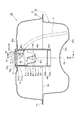
図1は、本発明の第1の実施の形態に係る燃料タンク構造が適用された自動二輪車の左側面図である。
自動二輪車1(鞍乗型車両)の前部には前輪2が回転自在に設けられ、前輪2の上方にはフロントフェンダ3が設けられる。フロントフェンダ3の上方には前輪2を操向させるバーハンドル4が設けられている。車体フレーム5の前端に形成されたヘッドパイプ6にはステアリングステム7が回転可能に支持され、バーハンドル4はステアリングステム7の上部に設けられている。
Hereinafter, a fuel tank structure of a saddle-ride type vehicle according to each embodiment of the present invention will be described with reference to the drawings. Note that the directions such as front, rear, left and right in the following description are the same as those in the vehicle described below unless otherwise specified. In addition, arrows FR indicating the front of the vehicle, an arrow LH indicating the left side of the vehicle, and an arrow UP indicating the upper side of the vehicle are shown at appropriate positions in the drawings used for the following description.
[First Embodiment]
FIG. 1 is a left side view of a motorcycle to which a fuel tank structure according to a first embodiment of the present invention is applied.
A
ステアリングステム7の下部には左右に延在する板状のロアブリッジ8が設けられ、ロアブリッジ8の左右端部には、左右一対のフロントフォーク9の上端が固定され、前輪2はフロントフォーク9の下部に回転自在に支持されている。
車体フレーム5は、ヘッドパイプ6から後斜め下方に延出する矩形断面の一本の鋼製パイプ材で構成されるメインフレーム10と、メインフレーム10の後端部から左右に分岐して略水平に後方に延出した後、後斜め上方に延出し、その後に略水平に後方に延出するシートレール11と、メインフレーム10の後端部から下方に延出するピボットプレート10aとを備える。
The lower part of the
The vehicle body frame 5 includes a
ピボットプレート10aの前方であってメインフレーム10の後部下方には、空冷単気筒のエンジン12が支持される。シートレール11の上方には、乗員が着座するシート13が配置され、シート13の下方には、シートレール11の周囲を覆うリヤカバー25が設けられる。シート13は前後に長く、シート13の前部上面は運転者用の着座面とされ、後部上面が同乗者用の着座面とされる。
An air-cooled single-
エンジン12は、クランク軸(不図示)を車幅方向に沿わせた状態で配置される。エンジン12のクランクケース12aの前端部からは、シリンダ12bが略水平の状態で前方に向けて突出する。クランクケース12aの後部はピボットプレート10aに支持され、クランクケース12aの上部はメインフレーム10から延出するエンジンハンガ10bに支持される。
The
自動二輪車1においては、シート13の前方でメインフレーム10の上方、より正確には、シート13とヘッドパイプ6との間であって、メインフレーム10の上方かつメインフレームカバー23の上方に、運転者がシート13に着座する際に跨ぐ跨ぎ空間Sが形成される。クランクケース12aの下部には、シート13に着座した運転者が足を載せるステップ28が支持される。ピボットプレート10aの下端部には、車体を直立状態で支持するメインスタンド29aが格納可能に支持される。ステップ28の基端近傍で自動二輪車1の車体中心線CL(図3、図4等参照)よりも左側のクランクケース12aの下面には、自動二輪車1を、車体が左側に傾いた起立状態で支持するサイドスタンド29bが格納可能に支持される。
In the
ピボットプレート10aには、スイングアーム15の前端部を支持するピボットシャフト14が支持され、スイングアーム15はピボットシャフト14を中心に上下に揺動自在に支持される。後輪16は、スイングアーム15の後端部に支持される。スイングアーム15の後部とシートレール11との間には、リヤクッション17が介装される。
A pivot shaft 14 that supports the front end of the
エンジン12のシリンダ12bの上部には、スロットルボディ18の下流側が接続され、スロットルボディ18の上流側には、エアクリーナーボックス18aが接続される。シリンダ12bの下部からは排気管19が導出され、排気管19は後方に湾曲して延びて、後輪16の右側方で後上がりに配置されたサイレンサ19aに接続される。
A downstream side of the
自動二輪車1の車体カバー20は、複数の樹脂製カバーから構成される。詳細には、車体カバー20は、バーハンドル4の中央側を覆うハンドルカバー21と、ハンドルカバー21よりも下方でヘッドパイプ6の前方を覆うフロントカバー22と、フロントカバー22の後端に接続され、主にメインフレーム10を囲うメインフレームカバー23と、フロントカバー22及びメインフレームカバー23の下端に接続されエンジン12のシリンダ12bの側方を覆う下部カバー24と、メインフレームカバー23及び下部カバー24の後端に接続されてシート13の下方を覆うリヤカバー25とを備えている。
The vehicle body cover 20 of the
シートレール11の後部の後方延出部30には、燃料タンク26の前後端部がそれぞれ支持される。後方延出部30の前端部30aには、シート13の前部下方に配置された物品収納ボックス27の後端部が燃料タンク26の前端部とともに支持される。物品収納ボックス27の前端部には、シート13の前端部が車幅方向に延びる回動軸27aを介して支持され、この回動軸27aを中心にシート13が上下方向に回動することで、物品収納ボックス27及び燃料タンク26へのアクセスが可能となる。
The front and rear end portions of the
図2は、燃料タンク26の左側面図である。図3は、燃料タンク26を上方から見た平面図である。
図2及び図3を参照し、燃料タンク26は、略水平な分割面B1上で上下分割体32,33を一体に接合した略直方体形状の中空のタンク本体31を有する。上分割体32は下方に開口する容器形状を有し、下分割体33は上方に開口する容器形状を有する。上下分割体32,33は、それぞれプレス成形品であり、上分割体32の下方開口端と下分割体33の上方開口端とが、分割面B1に沿うフランジF1を介して一体に溶接される。
FIG. 2 is a left side view of the
2 and 3, the
タンク本体31の上分割体32における略水平な上壁部32aの後部には、タンク本体31内に連通する上面視で円形の給油用開口34が形成される。給油用開口34は、上壁部32aにおける車幅方向の中央に設けられ、給油用開口34は、着脱可能な給油口キャップ35(燃料キャップ)で塞がれる。
上壁部32aの前部左側には、段差状に下方に変位するとともに僅かに前下がりに傾斜する左前平坦部32bが形成される。この左前平坦部32bには開口32cが形成され、開口32cの周囲には上方からブラケット32dが固定される。タンク本体31内の燃料をエンジン12に供給する燃料ポンプ36は、ブラケット32dを介して、タンク本体31内に臨んだ状態で設けられる。
In the rear portion of the substantially horizontal
A left front
ここで、自動二輪車1は、エンジン12の燃料としてエタノール含有燃料を用いることもできる車両であり、燃料タンク26にはエタノール含有燃料が貯留される。この燃料タンク26の給油用開口34には、円筒状に形成され燃料タンク26内へ延びる給油口装置40が設けられる。
Here, the
図4は、図2におけるIV−IV断面図である。図5は、図3におけるV−V断面図である。
図4及び図5に示すように、給油口装置40は、給油用開口34の下方に連なってタンク本体31内に延びる給油口としての給油案内筒41(筒部)と、給油案内筒41の下方開口部を覆うように設けられる円筒状のフレイムアレスタ42と、フレイムアレスタ42内に設けられて給油ガンのノズルGの挿入量を規制するガンストッパ体43と、給油案内筒41の内周面41dに係合する円筒状リング51(筒状ばね板部材)とを備えて構成されている。
タンク本体31の下壁部33aにおける車幅方向の中央部には、この下壁部33aの下方に位置する後輪16の上方への揺動範囲を確保する凹部33b(図4参照)が形成される。
4 is a cross-sectional view taken along the line IV-IV in FIG. 5 is a cross-sectional view taken along line VV in FIG.
As shown in FIGS. 4 and 5, the
A
給油用開口34の周縁部には、上方に突出した環状の額部34a(燃料キャップ用係合部)が形成されている。給油口キャップ35は額部34aに係合される。額部34a及び給油案内筒41は、ノズルGが挿入される給油口55を構成している。
額部34aは上壁部32aの板部を折り曲げて断面山型に形成され、給油用開口34を周方向に一周している。額部34aは、下方に折り返されて形成された円筒状の内周壁部34bを有し、内周壁部34bは、概ね上下方向に延在する給油口軸線C1に沿ってタンク本体31内へ下方に延びる。
この内周壁部34bの内径が給油用開口34の内径となる。図4には、給油用開口34の軸方向視における径を符号A1で示す。
An
The
The inner diameter of the inner
給油案内筒41は、給油用開口34と同軸で円筒状の周壁部41a(側面部)と、周壁部41aの上端外周に形成されるフランジ部41bとを有する。フランジ部41bは、額部34aの外周側において上壁部32aの平坦部分にタンク本体31内の下方から当接し、溶接等によって上壁部32aに一体に結合される。
また、周壁部41aには、周壁部41aの下端を径方向の内側に折り曲げて内方側折り曲げ部41cが形成されている。内方側折り曲げ部41cの内径は、給油用開口34の径A1よりも大径に形成されている。
The oil
In addition, an inner side
フレイムアレスタ42は、円筒状のアレスタ周壁部42aと、アレスタ周壁部42aの下端開口を閉塞するキャップ部材44とを有している。
フレイムアレスタ42は、アレスタ周壁部42aの上部42cの内周面が給油案内筒41の周壁部41aの外周面に嵌合され、この状態で溶接されることで給油案内筒41に接合される。フレイムアレスタ42は上下に長く形成され、アレスタ周壁部42aの下端及びキャップ部材44は、分割面B1よりも下方に位置している。
The
The
アレスタ周壁部42aは、例えば鋼板に、多数の連通孔42fを形成したメッシュ部42bを有している。ここでは、アレスタ周壁部42aは、鋼板に多数の小孔が形成されたいわゆるパンチングメタルを、筒状に成形して構成されている。
また、キャップ部材44は、パンチングメタルを、下方に開放する比較的上下に浅い有底円筒状に形成して設けられている。キャップ部材44の周壁部44a及び底壁部44bには、多数の連通孔42fが形成され、キャップ部材44はメッシュ状に形成されている。キャップ部材44は、周壁部44aがフレイムアレスタ42の下部42dに溶接されて固定されている。
The arrester
The
このように、フレイムアレスタ42は、アレスタ周壁部42a及びキャップ部材44が多数の連通孔42fを有してメッシュ状に形成されており、これら連通孔42fを通ることで、燃料がタンク本体31内に流通可能であるとともに、タンク本体31内の空気が外部に排出される。また、給油用開口34から火種が入った場合、フレイムアレスタ42によって火種を捕集でき、火種のタンク本体31内への侵入を防止できる。さらに、フレイムアレスタ42が金網ではなく、パンチングメタルで構成されているため、フレイムアレスタ42の強度及び耐熱性を向上できる。
Thus, in the
ガンストッパ体43は、給油案内筒41の下方に設けられて給油ガンのノズルGのタンク本体31内への挿入量を規制するとともに、ノズルGのフレイムアレスタ42への接触を防止する。ガンストッパ体43は、フレイムアレスタ42の上部42cの内周面に沿って湾曲する一対の接合板部43aと、各接合板部43aから下方に延びる一対の支持腕部43bと、これら一対の支持腕部43bの下端の間に掛け渡される架設部43cとを一体に有する。
The
一対の接合板部43aは略長方形の板状に形成され、孔の無い平坦状とされる。各接合板部43aは、その長手方向を上部42cの周方向に沿わせ、かつ、上縁を給油案内筒41の内方側折り曲げ部41cの下面に突き当てられた状態で、上部42cの内周面に溶接される。
図3及び図4に示すように、接合板部43aの一方はフレイムアレスタ42内の斜め前左側に位置し、他方はフレイムアレスタ42内の斜め後右側に位置する。すなわち、一対の接合板部43aは、フレイムアレスタ42の径方向で対向して配置されている。
The pair of joining
As shown in FIGS. 3 and 4, one of the joining
一対の支持腕部43bは、対応する接合板部43aの下縁から下方に向けて帯状に延び、下側ほど幅を狭めて先細りに形成されている。接合板部43aと支持腕部43bとの境界には、径方向内側に突出した段部45が形成されており、段部45に連なる支持腕部43bは、フレイムアレスタ42のメッシュ部42bから離間した状態で、フレイムアレスタ42の上下方向の中間部まで下方に延びている。また、一対の支持腕部43bは、下方ほど給油口軸線C1に近づくように傾斜しており、支持腕部43b間の間隔は下方ほど小さくなっている。
The pair of
図3〜図5に示すように、架設部43cは、フレイムアレスタ42内を、フレイムアレスタ42の直径に沿うように横断する棒状に形成され、上方に凸の断面山形を有して直線状に延びている。給油の際には、ノズルGの先端部が架設部43cに当接することで、ノズルGのタンク本体31内への挿入量が規制される。
ガンストッパ体43の外周面は、アレスタ周壁部42aに全周に亘って囲われている。フレイムアレスタ42のメッシュ部42bへのノズルGの接触は、架設部43c及び支持腕部43bがノズルGに当接することで防止される。
As shown in FIGS. 3 to 5, the
The outer peripheral surface of the
図4及び図5に示すように、給油口装置40には、タンク本体31内に貯留されている燃料を抜き取る抜油ホースHをタンク本体31内に通すための抜油用開口60(開口)が形成されている。
抜油用開口60は、一方の接合板部43aの上方、すなわち、フレイムアレスタ42内において斜め前左側に位置する接合板部43aの上方に設けられている。詳細には、抜油用開口60は、給油案内筒41の周壁部41aを貫通する案内筒開口61と、フレイムアレスタ42の上部42cの側面を貫通するアレスタ開口62とによって構成されている。案内筒開口61及びアレスタ開口62は略円形の開口であり、フレイムアレスタ42は、案内筒開口61及びアレスタ開口62が互いに連通して同軸となる配置で給油案内筒41に溶接される。
As shown in FIGS. 4 and 5, the oil
The
抜油用開口60は、抜油ホースHによる燃料の抜き取り作業後には、円筒状リング51によって閉塞される。この円筒状リング51は、帯状の鋼板を円筒状に曲げて形成され、周方向に開放端を有する略C字状に形成されている。すなわち、円筒状リング51は、縮径させる方向の力が外周面に作用することで弾性的に撓み、上記開放端の間隔が小さくなって縮径する。
The
円筒状リング51は、その外周面51aが、周壁部41aの内周面41dに嵌合した状態で設けられ、内周側から抜油用開口60を閉塞する。円筒状リング51は、外力が作用していない自然状態よりも縮径された状態で内周面41dに嵌合されおり、内周面41dは、円筒状リング51の反力によって、内周面41dを押し広げるように付勢されている。
本第1の実施の形態では、内周面41dに付勢するように設けられる円筒状リング51によって抜油用開口60を閉塞するため、締結部材等を用いることなく簡単な構造で抜油用開口60を閉塞できるとともに、抜油用開口60を閉塞する作業を容易にできる。しかし、例えば、締結部材及び抜油用開口60を塞ぐ板材を用いて抜油用開口60を閉塞する場合、締結用の工具を挿入するためのスペースを確保する必要があるとともに、抜油用開口60の周辺にねじ山等の被締結部を形成する必要があり、構造が複雑になるとともに、閉塞する作業に手間がかかることになる。
The
In the first embodiment, the
円筒状リング51は、給油用開口34の額部34aと給油案内筒41の内方側折り曲げ部41cとの間に嵌め込まれている。詳細には、円筒状リング51は、リング上端51bが額部34aの内側面に当接し、リング下端51cが内方側折り曲げ部41cの上面に当接している。すなわち、円筒状リング51は、額部34a及び内方側折り曲げ部41cによって軸方向に位置決めされている。
このように、円筒状リング51は、内周面41dを付勢するように設けられるとともに、額部34a及び内方側折り曲げ部41cによって軸方向に位置決めされており、給油案内筒41に強固に取り付けられるため、自動二輪車1の振動等による円筒状リング51のガタツキが防止され、音の発生が防止される。
The
As described above, the
次に、抜油ホースHを用いた燃料の抜き取り作業、及び、円筒状リング51によって抜油用開口60を閉塞する作業について説明する。
自動二輪車1の完成検査の終了後等には、エンジン12の試運転のために燃料タンク26に給油された少量の燃料をタンク本体31内から抜き取る作業が行われる。
まず、作業者は、自動二輪車1をサイドスタンド29bで支持させ、燃料吸引装置(不図示)に接続された抜油ホースHを、図4及び図5に示すように、給油口55を介して、給油案内筒41内の斜め前左側に位置する抜油用開口60に通し、抜油ホースHの下端をタンク本体31内の左側面側の底部に到達させる。
Next, a fuel extraction operation using the oil extraction hose H and an operation of closing the
For example, after the completion inspection of the
First, the operator supports the
その後、作業者は、上記燃料吸引装置を作動させることで燃料を抜き取ることができ、抜き取り後には、抜油ホースHを引っ張ることで抜油ホースHをタンク本体31から取り外す。この際、自動二輪車1が車体左側に設けられたサイドスタンド29bで支持されているため、燃料は燃料タンク26内の左側に貯留されており、抜油ホースHを左側面側の底部に到達させることで、効率良く燃料を抜き取ることができる。すなわち、サイドスタンド29bと同じ側に抜油用開口60を形成することで、抜油ホースHを燃料が溜まっている側に到達させることができ、効率良く燃料を抜き取ることができる。
Thereafter, the operator can extract the fuel by operating the fuel suction device. After the extraction, the operator pulls the oil extraction hose H to remove the oil extraction hose H from the tank
図6は、抜油用開口60を円筒状リング51によって閉塞する作業を示す側面断面図である。
燃料の抜き取り作業の完了後には、図6に示すように、抜油用開口60を円筒状リング51によって閉塞する作業が、組み付け治具65(筒状組み付け部材)を用いて行われる。
組み付け治具65は、円筒状に形成されたガイド筒65aと、円筒状リング51を押し出す円筒状の押圧筒65bとを有している。押圧筒65bには、ガイド筒65aに収容された円筒状リング51を押し出すための円筒状リング51がセットされている。
FIG. 6 is a side sectional view showing an operation of closing the
After completion of the fuel extraction operation, as shown in FIG. 6, the operation of closing the
The assembling
ガイド筒65aは、軸方向に複数の円筒状リング51を収容可能な長さを有し、外周部の径は、ガイド筒65aを給油口55に挿入可能なように給油用開口34の径A1よりも小径に形成されている。ガイド筒65aの下部の外周面には径方向に突出したフランジ部66が形成されており、フランジ部66が額部34aの上面に当接することで、ガイド筒65aの給油案内筒41への挿入量が規制される。ガイド筒65aの内径は、内周面41dに嵌合された状態の円筒状リング51の外径よりも小径に形成されており、円筒状リング51は、縮径された状態でガイド筒65aの内側に収容される。
The
円筒状リング51による閉塞作業に際し、作業者は、円筒状リング51がセットされた状態のガイド筒65aの下部を給油口55に挿入してガイド筒65aをタンク本体31に接続し、その後、押圧筒65bによってガイド筒65a内の円筒状リング51を下方に押し出す。押し出された円筒状リング51は、ガイド筒65aの内周面にガイドされて給油案内筒41内に落下し、復元力によって落下中に拡径し、図6に2点鎖線で示すように、ガンストッパ体43の支持腕部43bの内周面に嵌まる。
When the
次いで、作業者は、工具等を使用して円筒状リング51を上方に引き上げる。すると、給油案内筒41まで引き上げられた円筒状リング51は復元力によってさらに拡径しつつ内周面41dに嵌合し、これに伴い、抜油用開口60が円筒状リング51によって閉塞される。これにより、抜油用開口60からの火種の侵入を防止できる。
第1の実施の形態では、額部34aの内周壁部34bの下端と内方側折り曲げ部41cの上面との間の間隔は円筒状リング51の軸方向長さよりも小さく形成されているが、円筒状リング51を給油案内筒41内に落下させてリング上端51bを内周壁部34bの下端よりも一端下げ、その後、円筒状リング51を引き上げるようにしているため、円筒状リング51を内周面41dに嵌合させることができる。
Next, the operator pulls the
In the first embodiment, the interval between the lower end of the inner
また、閉塞作業の際に、給油案内筒41の下方のガンストッパ体43が架設部43cを有しており、落下した円筒状リング51が架設部43cを超えて下方のタンク本体31内に脱落することが防止されるため、閉塞作業の作業性を向上できる。
さらに、一対の支持腕部43bは、支持腕部43b間の間隔が下方ほど小さくなるように傾斜しているため、円筒状リング51が外周面51aの全面で支持腕部43bに強固に嵌まることを防止でき、円筒状リング51を容易に引き上げできるため、閉塞作業の作業性を向上できる。
Further, during the closing operation, the
Furthermore, since the pair of
以上説明したように、本発明を適用した第1の実施の形態によれば、燃料タンク26の給油口55の内側に配置されるフレイムアレスタ42を設けた構成においても、筒形状の給油案内筒41の周壁部41a及びフレイムアレスタ42に設けた抜油用開口60を用いて燃料タンク26内の燃料を抜き取りできるとともに、周壁部41aに付勢するように設けられる円筒状リング51によって抜油用開口60を閉塞できる。これにより、給油口装置40からの燃料の抜き取りが可能な燃料タンク構造を簡単な構造で実現するとともに、円筒状リング51で抜油用開口60を閉塞でき、抜油用開口60を閉塞する作業を容易にできる。
As described above, according to the first embodiment to which the present invention is applied, even in the configuration in which the
また、円筒状リング51の位置決めを給油口キャップ35が係合する額部34aで行うため、円筒状リング51を位置決めするためだけの部品を設ける必要がない。このため、部品点数を増加させることなく円筒状リング51を設けることができる。
また、給油口装置40の給油案内筒41の下端に形成された内方側折り曲げ部41cによって下端側の強度を向上させることができるとともに、この内方側折り曲げ部41cによって円筒状リング51を軸方向に位置決めできるため、部品点数の削減及び生産性の向上を図ることができる。
Further, since the positioning of the
Further, the strength of the lower end side can be improved by the inner side
さらに、円筒状リング51を給油案内筒41に組み付ける際に、給油案内筒41の下端より下方に位置するガンストッパ体43の架設部43cによって円筒状リング51の燃料タンク26内への脱落を規制できるため、生産性を向上させることができる。
さらにまた、円筒状リング51が、給油口装置40の給油口55に接続された組み付け治具65の内周にガイドされて給油案内筒41に挿入されるため、組み付けの作業性を向上できる。
また、円筒状リング51がフレイムアレスタ42よりも上方に設けられているため、フレイムアレスタ42のメッシュ部42bを塞ぐことなく円筒状リング51を設けることができ、給油用開口34からの給油をスムーズに行うことができる。
Further, when the
Furthermore, since the
Further, since the
なお、上記第1の実施の形態は本発明を適用した一態様を示すものであって、本発明は上記第1の実施の形態に限定されるものではない。
上記第1の実施の形態では、抜油用開口60は、案内筒開口61及びアレスタ開口62によって構成されているものとして説明したが、本発明はこれに限定されるものではなく、例えば、周壁部41aがアレスタ周壁部42aに覆われていない構成では、周壁部41aに案内筒開口61を設けるだけで抜油用開口60を形成できる。また、自動二輪車1の細部構成については任意に変更可能であることは勿論である。
また、上記第1の実施の形態では、鞍乗型車両である自動二輪車1を例に挙げて説明したが、本発明は汎用発電機や農機の燃料タンク構造にも適用可能である。
In addition, the said 1st Embodiment shows the one aspect | mode which applied this invention, Comprising: This invention is not limited to the said 1st Embodiment.
In the first embodiment, the
In the first embodiment, the
[第2の実施の形態]
以下、図7を参照して、本発明を適用した第2の実施の形態について説明する。この第2の実施の形態において、上記第1の実施の形態と同様に構成される部分については、同符号を付して説明を省略する。
第2の実施の形態では、上記第1の実施の形態の内方側折り曲げ部41cが設けられておらず、円筒状リング51が、ガンストッパ体43の段部45に位置決めされている点が第1の実施の形態と異なる。
[Second Embodiment]
Hereinafter, a second embodiment to which the present invention is applied will be described with reference to FIG. In the second embodiment, parts that are configured in the same manner as in the first embodiment are given the same reference numerals, and descriptions thereof are omitted.
In the second embodiment, the inner side
図7は、第2の実施の形態における給油口装置40の断面図である。
図7に示すように、給油案内筒41は、フランジ部41bと、フランジ部41bに連なる円筒状の周壁部141a(側面部)を有している。周壁部141aには、案内筒開口61が形成されている。
ガンストッパ体43は、接合板部43aの上縁を周壁部141aの下端に突き当てられた状態で、上部42cの内周面に溶接される。接合板部43aの内周面及び周壁部141aの内周面は連続し、円筒状リング51の外周面51aが嵌合する内周面141dを構成している。
FIG. 7 is a cross-sectional view of the
As shown in FIG. 7, the oil
The
円筒状リング51は、リング上端51bが額部34aの内側面に当接し、リング下端51cがガンストッパ体43の段部45の上面に当接している。すなわち、円筒状リング51は、額部34a及び段部45によって軸方向に位置決めされている。
第2の実施の形態では、円筒状リング51のリング下端51cの位置決めをガンストッパ体43の段部45によって行うため、リング下端51cを位置決めするためだけの部品を設ける必要がない。このため、部品点数を増加させることなく円筒状リング51を設けることができる。
In the
In the second embodiment, since the ring
[第3の実施の形態]
以下、図8〜図13を参照して、本発明を適用した第3の実施の形態について説明する。
この第3の実施の形態において、上記第1の実施の形態と同様に構成される部分については、同符号を付して説明を省略する。
[Third Embodiment]
Hereinafter, a third embodiment to which the present invention is applied will be described with reference to FIGS.
In the third embodiment, parts that are configured in the same manner as in the first embodiment are given the same reference numerals, and descriptions thereof are omitted.
図8は、第3の実施の形態の燃料タンク構造が適用された自動二輪車の左側面図である。
図8に示す自動二輪車101において、その車体フレーム102は、前輪懸架系を操向可能に支持するヘッドパイプ103と、ヘッドパイプ103から後方に延びた後に屈曲して後斜め下方に延びるメインフレーム104と、メインフレーム104の下方でヘッドパイプ103から後斜め下方に延びるダウンチューブ105と、メインフレーム104の後部に連結されて後輪懸架系のリヤスイングアーム112を上下に揺動可能に支持する左右一対のピボットプレート106と、メインフレーム104から後方に延びるシートフレーム115とを備える。
FIG. 8 is a left side view of a motorcycle to which the fuel tank structure of the third embodiment is applied.
In the
左右一対のフロントフォーク108は、ヘッドパイプ103を介して支持され、前輪107はフロントフォーク108の下端に支持される。操向用のハンドル109は、フロントフォーク108の上部に設けられる。エンジン110は車体フレーム102に支持され、後輪111は、リヤスイングアーム112の後部に支持される。シートフレーム115とリヤスイングアーム112との間にはリヤクッション113が設けられ、乗員用のシート114はシートフレーム115に支持されている。自動二輪車101の車体を左側に傾けた起立状態で支持するサイドスタンド116は、左側のピボットプレート106の下部に設けられ、車体中心線に対して左側に配置される。
The pair of left and right
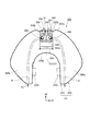
図9は、燃料タンク326の側面断面図である。図10は、燃料タンク326の正面断面図である。
燃料タンク326は、シート114(図8参照)の前方に設けられ、メインフレーム104上に支持される。燃料タンク326の鞍型のタンク本体331は、タンク外観を形成する外分割体332と、内側部及び下部を形成する内分割体333とを有し、外分割体332と内分割体333とを外分割体332の下縁のフランジF2を介して一体に溶接し、中空に形成される。
FIG. 9 is a side sectional view of the
The
燃料タンク326の下部において車幅方向中央には、内分割体333を上方に窪ませて形成した逃げ部333bが形成され、逃げ部333bにはメインフレーム104が通される。逃げ部333bの側面には、燃料タンク326をメインフレーム104に連結する連結部333cが設けられている。
燃料タンク326の前部は、逃げ部333bによって左右の室に仕切られており、燃料が少ない状態では、燃料は左室326a及び右室326bに別々に溜まる。
In the lower part of the
The front portion of the
タンク本体331の上壁部332aの前部には下方へ段差状に窪んだ平坦部332bが形成され、平坦部332bには、上面視で円形のタンク上面開口334が形成される。タンク上面開口334は、タンク本体331において、車幅方向の中央に設けられ、逃げ部333bの上方に位置している。
タンク上面開口334の周縁部には、上壁部332aの板部をタンク本体331内の下方に曲げて形成した円筒状の短フランジ334bが形成される。
内分割体333の下壁部333aの後部にはブラケット132dが設けられ、燃料ポンプ136はブラケット132dを介して取り付けられる。
A
A cylindrical
A
燃料タンク326にはエタノール含有燃料が貯留され、燃料タンク326のタンク上面開口334には、円筒状に形成され燃料タンク326内へ延びる給油口装置340が設けられる。
図11は、図10における給油口装置340の拡大図である。図12は、給油口装置340の分解斜視図である。
図11及び図12に示すように、給油口装置340は、タンク上面開口334の下方に連なってタンク本体331内に延びる円筒状のフィラーメタル341(フィラーメタル部材)と、フィラーメタル341の内側に設けられる円筒状のガンストッパ部材343と、フィラーメタル341の下方開口部を覆うように設けられる円筒状のフレイムアレスタ342と、ガンストッパ部材343の内周面343eに係合する円筒状リング51(筒状ばね板部材)とを備えて構成されている。フィラーメタル341及びガンストッパ部材343は、ノズルGが挿入される円筒状の給油口355を構成している。
An ethanol-containing fuel is stored in the
FIG. 11 is an enlarged view of the
As shown in FIGS. 11 and 12, the
フィラーメタル341は、タンク上面開口334と同軸で円筒状のフィラー周壁部341aと、フィラーメタル341の上部341bに形成される額部341cとを有する。額部341cは、下方に折り返されて形成された円筒状の内周壁部341dを有し、内周壁部341dは、概ね上下方向に延在する給油口軸線C1に沿ってタンク本体331内へ下方に延びる。この内周壁部341dの内径は、給油ガンのノズルG(図11参照)が挿通される給油口355の入口の内径となる。着脱可能な給油口キャップ(不図示)は、額部341cに取り付けられる。
The
フィラーメタル341は、フィラー周壁部341aの外周面を短フランジ334bの内周面に嵌合させた状態で短フランジ334bに溶接されて固定される。詳細には、フィラーメタル341は、上部341bが平坦部332bよりも突出し、燃料タンク326の外方側に露出した状態で固定される。
また、フィラーメタル341には、フィラー周壁部341aを貫通する円形のフィラー開口362が形成されている。フィラー開口362は、フィラー周壁部341aの前面側の下部において、車体中心線CL(図10参照)を挟んで左右2箇所に形成されている。
The
The
ガンストッパ部材343は、フィラーメタル341の下部に設けられて給油ガンのノズルGのタンク本体331内への挿入量を規制するとともに、ノズルGのフレイムアレスタ42への接触を防止する。
ガンストッパ部材343は、フィラー周壁部341aの内周面に沿う円筒状のストッパ周壁部343a(円筒状側面、側面部)と、ガンストッパ部材343の円形の底部開口面343bを横断するように設けられる架設部343c(ガンストッパ)と、ストッパ周壁部343aの上端から内側に屈曲して上方に延びる上側折り曲げ部351(上側の折り曲げ部)とを一体に備えている。
ガンストッパ部材343は、ストッパ周壁部343aの外周面がフィラー周壁部341aの内周面に嵌合した状態で、この嵌合部を溶接することでフィラーメタル341に固定される。
The
The
The
架設部343cは、ストッパ周壁部343aの軸方向に直交する棒状に形成され、互いに平行に2本が設けられている。詳細には、各架設部343cは、ストッパ周壁部343aの下縁から下方に突出する一対の突出壁353と、一対の突出壁353の下端の間に掛け渡される棒部354とを有している。
上側折り曲げ部351は、ストッパ周壁部343aの周方向に互いに略等間隔をあけて4か所に設けられている。
The
The upper
ストッパ周壁部343aには、ストッパ周壁部343aを貫通する円形のストッパ開口361が形成されている。ストッパ開口361は各フィラー開口362に対応した2箇所に形成され、ガンストッパ部材343をフィラーメタル341に固定した状態では、フィラー開口362に連通する。給油口装置340では、ストッパ開口361とフィラーメタル341とが重なって連通することで、2つの抜油用開口360(開口)が形成され、各抜油用開口360には、抜油ホースHを挿通することができる。
A
フレイムアレスタ342は、円筒状のアレスタ周壁部342aと、アレスタ周壁部342aの下端開口を閉塞するキャップ部材344とを有している。
フレイムアレスタ342は、アレスタ周壁部342aの上部342cの内周面がフィラー周壁部341aの下部の外周面に嵌合され、この嵌合部が溶接されることでフィラーメタル341に固定される。
The
The
アレスタ周壁部342aは、パンチングメタルにより構成されており、多数の連通孔42fが形成されたメッシュ部342bを有している。
また、キャップ部材344は、パンチングメタルを、下方に開放する比較的上下に浅い有底円筒状に形成して設けられている。キャップ部材344には多数の連通孔42fが形成され、キャップ部材344はメッシュ状に形成されている。キャップ部材344は、フレイムアレスタ342の下部342dの内周面に溶接されて固定されている。
The arrester
The
図10に示すように、各抜油用開口360には抜油ホースHが挿通され、抜油ホースHを介して燃料タンク326の燃料は抜き取られる。各抜油用開口360は、抜油ホースHによる燃料の抜き取り作業後に、ガンストッパ部材343に取り付けられる円筒状リング51によって閉塞される。
As shown in FIG. 10, an oil removal hose H is inserted into each
図13は、給油口装置340の断面図である。
図11〜図13を参照し、円筒状リング51は、外周面51aがストッパ周壁部343aの内周面343eに嵌合されて組み付けられ、この状態では、円筒状リング51は自然状態よりも縮径されており、外周面51aは内周面343eを押し広げる方向に付勢している。
本第3の実施の形態では、内周面343eに付勢するように設けられる円筒状リング51によって各抜油用開口360を閉塞するため、締結部材等を用いることなく簡単な構造で各抜油用開口360を閉塞できるとともに、各抜油用開口360を閉塞する作業を容易にできる。
FIG. 13 is a cross-sectional view of the
11 to 13, the
In the third embodiment, each
図13に示すように、ストッパ周壁部343aの下縁には、ストッパ周壁部343aの板部を径方向内側に折り曲げて形成した下側折り曲げ部352が設けられている。下側折り曲げ部352は、ストッパ周壁部343aの下縁に沿って円弧状に連続し、下側折り曲げ部352の曲げの基端部を含む上面部は、リング下端51cが当接する支持部となっている。
上側折り曲げ部351は、ストッパ周壁部343aの上縁から径方向内側に向けて上方に延び、その後、中間部で径方向外側に折り返されており、中間部から上方に向けて径方向外側に延びる折り返し部351aを有している。また、上側折り曲げ部351の曲げの基端部351bは、リング上端51bが当接する支持部となっている。
As shown in FIG. 13, a lower
The upper
すなわち、ストッパ周壁部343aの上下位置には、上側折り曲げ部351及び下側折り曲げ部352が設けられており、円筒状リング51は、上側折り曲げ部351と下側折り曲げ部352との間に嵌め込まれることで上下方向(軸方向)に位置決めされている。
このように、円筒状リング51は、内周面343eを付勢するように設けられるとともに、上側折り曲げ部351及び下側折り曲げ部352によって軸方向に位置決めされており、ガンストッパ部材343に強固に取り付けられるため、自動二輪車101の振動等による円筒状リング51のガタツキが防止され、音の発生が防止される。
また、上側折り曲げ部351が径方向外側に延びる折り返し部351aを有しているため、給油ガンのノズルGが上側折り曲げ部351に接触したとしても、ノズルGは、内側の下方に傾斜する折り返し部351aによって下方にガイドされる。このため、上側折り曲げ部351へのノズルGの引っ掛かりを防止でき、給油の作業性を向上できる。
また、燃料タンク326内に貯留される燃料の上限位置は、下側折り曲げ部352の位置に略一致している。
That is, an upper
Thus, the
In addition, since the upper
Further, the upper limit position of the fuel stored in the
図10に示すように、燃料タンク326から燃料を抜き取る際には、各抜油用開口360に抜油ホースHが接続される。本第3の実施の形態では、左室326a及び右室326bに対応させて、各抜油用開口360を車体中心線CLを挟んで左右に設けたため、抜油ホースHを燃料タンク326の底部まで容易に到達させることができ、効率良く燃料を抜き取ることができる。
As shown in FIG. 10, when the fuel is extracted from the
燃料の抜き取り作業の完了後には、第1の実施の形態と同様に、給油口355に挿入される組み付け治具65(図6参照)によって、円筒状リング51がガンストッパ部材343に組み付けられる。すなわち、円筒状リング51は、縮径された状態でガイド筒65aの内周面にガイドされてストッパ周壁部343a内に落下し、その後、作業者によって位置を調整され、内周面343eに嵌合する。この際、ストッパ周壁部343aの下方に架設部343cが設けられており、落下した円筒状リング51が架設部343cを超えて下方のタンク本体331内に脱落することが防止されるため、閉塞作業の作業性を向上できる。
After completion of the fuel extraction operation, the
以上説明したように、本発明を適用した第3の実施の形態によれば、ガンストッパ部材343のストッパ周壁部343aの上下位置に形成した上側折り曲げ部351及び下側折り曲げ部352によって円筒状リング51を軸方向に位置決めするため、円筒状リング51を位置決めするためだけの部品を設ける必要が無く、部品点数を増加させずに円筒状リング51を設けることができる。また、比較的複雑な形状を有するガンストッパ部材343をフィラーメタル341とは別に設けてフィラーメタル341に溶接しているため生産性が向上する。
また、ガンストッパ部材343に形成される上側折り曲げ部351に折り返し部351aが形成されているため、この折り返し部351aによって給油時にノズルGの上側折り曲げ部351への引っ掛かりを防止でき、給油の作業性を向上できる。
As described above, according to the third embodiment to which the present invention is applied, the cylindrical ring is formed by the upper
In addition, since the folded
なお、上記第3の実施の形態は本発明を適用した一態様を示すものであって、本発明は上記第3の実施の形態に限定されるものではない。
上記第3の実施の形態では、ガンストッパ部材343は、ストッパ周壁部343aの外周面がフィラー周壁部341aの内周面に嵌合した状態で、この嵌合部を溶接することでフィラーメタル341に固定されるものとして説明したが、本発明はこれに限定されるものではない。例えば、図14の給油口装置の側面断面図に示すように、フレイムアレスタ342のアレスタ周壁部342aの内周面にストッパ周壁部343aの外周面を嵌合させて溶接し、その後、アレスタ周壁部342aの上部の外周面を、フィラー周壁部341aの下部の内周面に嵌合させ、この嵌合部を溶接しても良い。
The third embodiment shows one aspect to which the present invention is applied, and the present invention is not limited to the third embodiment.
In the third embodiment, the
26、326 燃料タンク
34a 額部(燃料キャップ用係合部)
35 給油口キャップ(燃料キャップ)
41 給油案内筒(筒部)
41a、141a 周壁部(側面部)
41c 内方側折り曲げ部
42、342 フレイムアレスタ
43 ガンストッパ体
51 円筒状リング(筒状ばね板部材)
55 給油口
60、360 抜油用開口(開口)
65 組み付け治具(筒状組み付け部材)
341 フィラーメタル(フィラーメタル部材)
343 ガンストッパ部材
343a ストッパ周壁部(円筒状側面、側面部)
343b 底部開口面
343c 架設部(ガンストッパ)
351 上側折り曲げ部(折り曲げ部、上側の折り曲げ部)
351a 折り返し部
352 下側折り曲げ部(折り曲げ部)
355 給油口
G ノズル
26, 326
35 Filler cap (fuel cap)
41 Refueling guide tube (cylinder part)
41a, 141a Peripheral wall (side surface)
41c Inner side bent
55 Refueling
65 Assembly jig (tubular assembly member)
341 Filler metal (filler metal member)
343
343b
351 Upper folded part (folded part, upper folded part)
351a Folding
355 Refueling port G Nozzle
Claims (8)
前記給油口(55、355)の側面部(41a、141a、341a)には開口(60、360)が形成され、
前記給油口(55、355)の前記側面部(41a、141a、341a)に付勢するように配置されるとともに前記開口(60、360)を閉塞する筒状ばね板部材(51)が設けられていることを特徴とする燃料タンク構造。 A fuel tank (26, 326), a fuel supply port (55, 355) formed in a cylindrical shape and provided in the fuel tank (26, 326), and a fuel tank (26 326) and a flame arrester (42, 342) disposed inside,
Openings (60, 360) are formed in the side surfaces (41a, 141a, 341a) of the fuel filler port (55, 355),
A cylindrical spring plate member (51) is provided that is arranged to urge the side surface portions (41a, 141a, 341a) of the fuel filler port (55, 355) and closes the openings (60, 360). A fuel tank structure characterized by that.
前記給油口(55)に形成される燃料キャップ用係合部(34a)が前記燃料タンク(26)内に延出して形成され、該燃料キャップ用係合部(34a)が前記筒状ばね板部材(51)を軸方向に位置決めすることを特徴とする請求項1記載の燃料タンク構造。 A fuel cap (35) engaged to close the fuel filler port (55);
A fuel cap engagement portion (34a) formed in the fuel filler opening (55) is formed extending into the fuel tank (26), and the fuel cap engagement portion (34a) is formed in the cylindrical spring plate. 2. The fuel tank structure according to claim 1, wherein the member (51) is positioned in the axial direction.
前記ガンストッパ部材(343)の円筒状側面(343a)に前記開口(360)が形成されるとともに、前記円筒状側面(343a)の上下位置に折り曲げ部(351、352)を形成し、該折り曲げ部(351、352)によって前記筒状ばね板部材(51)を軸方向に位置決めすることを特徴とする請求項1記載の燃料タンク構造。 The filler port (355) is exposed to the outer side of the fuel tank (326) and formed in a cylindrical shape with a filler metal member (341), and a cylindrical shape provided inside the filler metal member (341). A gun stopper member (343), the gun stopper member (343) having a gun stopper (343c) formed at the bottom so as to cross the bottom opening surface (343b),
The opening (360) is formed in the cylindrical side surface (343a) of the gun stopper member (343), and bent portions (351, 352) are formed at the upper and lower positions of the cylindrical side surface (343a). The fuel tank structure according to claim 1, wherein the cylindrical spring plate member (51) is positioned in the axial direction by the portions (351, 352).
前記筒状ばね板部材(51)は、前記給油口(55、355)に接続された前記筒状組み付け部材(65)の内周にガイドされて前記給油口(55、355)に挿入されることを特徴とする請求項1から6のいずれかに記載の燃料タンク構造。 The cylindrical spring plate member (51) is urged into the cylindrical side surface portions (41a, 141a, 341a) of the oil filler port (55, 355). Set on the inner periphery of the cylindrical assembly member (65) formed to have a diameter smaller than the diameter,
The cylindrical spring plate member (51) is guided by the inner periphery of the cylindrical assembly member (65) connected to the oil supply port (55, 355) and inserted into the oil supply port (55, 355). The fuel tank structure according to any one of claims 1 to 6, wherein
Priority Applications (4)
| Application Number | Priority Date | Filing Date | Title |
|---|---|---|---|
| JP2010213587A JP5463254B2 (en) | 2010-09-24 | 2010-09-24 | Fuel tank structure |
| BRPI1104917A BRPI1104917B1 (en) | 2010-09-24 | 2011-09-22 | fuel tank structure |
| CN201110285440.2A CN102416993B (en) | 2010-09-24 | 2011-09-23 | Fuel tank structure |
| US13/241,395 US8448802B2 (en) | 2010-09-24 | 2011-09-23 | Fuel tank structure |
Applications Claiming Priority (1)
| Application Number | Priority Date | Filing Date | Title |
|---|---|---|---|
| JP2010213587A JP5463254B2 (en) | 2010-09-24 | 2010-09-24 | Fuel tank structure |
Publications (3)
| Publication Number | Publication Date |
|---|---|
| JP2012066714A JP2012066714A (en) | 2012-04-05 |
| JP2012066714A5 JP2012066714A5 (en) | 2013-07-25 |
| JP5463254B2 true JP5463254B2 (en) | 2014-04-09 |
Family
ID=45869612
Family Applications (1)
| Application Number | Title | Priority Date | Filing Date |
|---|---|---|---|
| JP2010213587A Expired - Fee Related JP5463254B2 (en) | 2010-09-24 | 2010-09-24 | Fuel tank structure |
Country Status (4)
| Country | Link |
|---|---|
| US (1) | US8448802B2 (en) |
| JP (1) | JP5463254B2 (en) |
| CN (1) | CN102416993B (en) |
| BR (1) | BRPI1104917B1 (en) |
Families Citing this family (13)
| Publication number | Priority date | Publication date | Assignee | Title |
|---|---|---|---|---|
| JP5048451B2 (en) * | 2007-10-23 | 2012-10-17 | 本田技研工業株式会社 | Refueling port device for vehicle fuel tank |
| JP2014201188A (en) * | 2013-04-04 | 2014-10-27 | ヤマハ発動機株式会社 | Fuel tank and saddle riding type vehicle |
| CN103255799B (en) * | 2013-05-13 | 2015-03-04 | 广西柳工机械股份有限公司 | Fuel collecting device of fuel tank |
| JP6086889B2 (en) * | 2014-09-30 | 2017-03-01 | 本田技研工業株式会社 | Rear fuel tank |
| JP6170517B2 (en) * | 2015-03-26 | 2017-07-26 | 本田技研工業株式会社 | Fuel tank for saddle-ride type vehicles |
| JP6649203B2 (en) * | 2016-08-09 | 2020-02-19 | 本田技研工業株式会社 | Saddle-type vehicle fuel tank |
| JP6492371B2 (en) * | 2016-09-30 | 2019-04-03 | 本田技研工業株式会社 | Fuel cap for saddle-ride type vehicles |
| JP6513759B2 (en) * | 2017-09-28 | 2019-05-15 | 本田技研工業株式会社 | Resin tank |
| JP7045848B2 (en) * | 2017-12-21 | 2022-04-01 | カワサキモータース株式会社 | Fuel tank |
| CN108556985B (en) * | 2018-05-29 | 2023-05-12 | 力帆实业(集团)股份有限公司 | Nylon fuel tank of motorcycle |
| US11807421B2 (en) | 2019-08-12 | 2023-11-07 | Surecan, Incorporated | Fill nozzle pass through flame mitigation device for portable fuel container |
| CN113400929B (en) * | 2021-07-30 | 2022-05-27 | 湖南湖大艾盛汽车零部件装备制造有限公司 | Structure of charging port or oil filling port actuator |
| JP7165435B1 (en) | 2021-08-18 | 2022-11-04 | 新倉工業株式会社 | fire screen |
Family Cites Families (18)
| Publication number | Priority date | Publication date | Assignee | Title |
|---|---|---|---|---|
| US1068193A (en) * | 1911-03-14 | 1913-07-22 | Sydney S Weil | Pressure expansion safety venting device. |
| US1203797A (en) * | 1915-09-30 | 1916-11-07 | Isaac E Sexton | Can for gasolene, &c. |
| US1814656A (en) * | 1928-07-09 | 1931-07-14 | Protectoseal Company Of Americ | Filling and venting device |
| US2244947A (en) * | 1939-12-04 | 1941-06-10 | William A Hargiss | Nozzle tube |
| US3465911A (en) * | 1968-05-08 | 1969-09-09 | Brode Milling Co Inc Van | Valved container |
| JPS6155361A (en) * | 1984-08-28 | 1986-03-19 | Nissan Motor Co Ltd | Fuel tank |
| US4653660A (en) * | 1984-10-17 | 1987-03-31 | Shaw James R | Insert for a fuel tank inlet and a method of installing the insert |
| JPH0431020U (en) * | 1990-07-06 | 1992-03-12 | ||
| US5439129A (en) * | 1994-07-06 | 1995-08-08 | Borg-Warner Automotive, Inc. | Fuel tank filler pipe arrangement |
| JPH08142690A (en) * | 1994-11-16 | 1996-06-04 | Daihatsu Motor Co Ltd | Inlet pipe of fuel tank |
| JPH1059252A (en) * | 1996-08-21 | 1998-03-03 | Suzuki Motor Corp | Tank fuel venting device for motorcycle |
| EP1040049A1 (en) * | 1997-04-08 | 2000-10-04 | Stant Manufacturing Inc. | Contaminant cover for tank filler neck closure |
| JP4163352B2 (en) * | 1999-11-15 | 2008-10-08 | 本田技研工業株式会社 | Fuel tank |
| JP2005047334A (en) * | 2003-07-31 | 2005-02-24 | Suzuki Motor Corp | Fuel tank of saddle type vehicle |
| DE102004002994B3 (en) * | 2004-01-19 | 2005-09-22 | Itw Automotive Products Gmbh & Co. Kg | Filler neck for filling fuel into a vehicle tank |
| JP5049737B2 (en) * | 2007-10-23 | 2012-10-17 | 本田技研工業株式会社 | Refueling port device for vehicle fuel tank |
| JP5048451B2 (en) * | 2007-10-23 | 2012-10-17 | 本田技研工業株式会社 | Refueling port device for vehicle fuel tank |
| JP2010084655A (en) * | 2008-09-30 | 2010-04-15 | Honda Motor Co Ltd | Mounting structure of fuel pump |
-
2010
- 2010-09-24 JP JP2010213587A patent/JP5463254B2/en not_active Expired - Fee Related
-
2011
- 2011-09-22 BR BRPI1104917A patent/BRPI1104917B1/en active IP Right Grant
- 2011-09-23 US US13/241,395 patent/US8448802B2/en not_active Expired - Fee Related
- 2011-09-23 CN CN201110285440.2A patent/CN102416993B/en active Active
Also Published As
| Publication number | Publication date |
|---|---|
| US20120074139A1 (en) | 2012-03-29 |
| CN102416993A (en) | 2012-04-18 |
| BRPI1104917B1 (en) | 2020-04-07 |
| JP2012066714A (en) | 2012-04-05 |
| CN102416993B (en) | 2014-07-30 |
| US8448802B2 (en) | 2013-05-28 |
| BRPI1104917A2 (en) | 2015-08-25 |
Similar Documents
| Publication | Publication Date | Title |
|---|---|---|
| JP5463254B2 (en) | Fuel tank structure | |
| JP5775560B2 (en) | Saddle riding | |
| US8616403B2 (en) | Fuel filler port device of fuel tank for straddled vehicle | |
| JP5436398B2 (en) | Vehicle fuel tank | |
| US20120181783A1 (en) | Saddle type vehicle | |
| JP5461272B2 (en) | Frame structure of saddle-ride type vehicle | |
| JP2011073629A (en) | Scooter type vehicle | |
| JP5411241B2 (en) | Saddle riding | |
| JP6644820B2 (en) | Saddle-type vehicle | |
| JP2020060193A (en) | Saddle ride-type vehicle | |
| JP6649971B2 (en) | Saddle type vehicle | |
| CN110475711B (en) | Saddle-ride type vehicle | |
| JP6190347B2 (en) | Scooter type vehicle | |
| JP6069232B2 (en) | Muffler mounting structure for small vehicles | |
| JP6513631B2 (en) | Gas-liquid separator arrangement structure for straddle-type vehicles | |
| JP4875053B2 (en) | Saddle riding | |
| EP3561245B1 (en) | Straddled vehicle | |
| JP6980632B2 (en) | Saddle-type vehicle | |
| WO2011121655A1 (en) | Fuel tank for vehicle | |
| JP2012167569A (en) | Vehicular exhaust structure | |
| JP6797953B2 (en) | Saddle-type vehicle | |
| JP5801142B2 (en) | Motorcycle | |
| JP6335835B2 (en) | Exhaust system | |
| CN220687438U (en) | Exhaust muffler device and saddle-type vehicle | |
| JP7478904B2 (en) | Saddle type vehicle |
Legal Events
| Date | Code | Title | Description |
|---|---|---|---|
| A621 | Written request for application examination |
Free format text: JAPANESE INTERMEDIATE CODE: A621 Effective date: 20121127 |
|
| A521 | Request for written amendment filed |
Free format text: JAPANESE INTERMEDIATE CODE: A523 Effective date: 20130612 |
|
| A977 | Report on retrieval |
Free format text: JAPANESE INTERMEDIATE CODE: A971007 Effective date: 20131212 |
|
| TRDD | Decision of grant or rejection written | ||
| A01 | Written decision to grant a patent or to grant a registration (utility model) |
Free format text: JAPANESE INTERMEDIATE CODE: A01 Effective date: 20140114 |
|
| A61 | First payment of annual fees (during grant procedure) |
Free format text: JAPANESE INTERMEDIATE CODE: A61 Effective date: 20140120 |
|
| R150 | Certificate of patent or registration of utility model |
Ref document number: 5463254 Country of ref document: JP Free format text: JAPANESE INTERMEDIATE CODE: R150 Free format text: JAPANESE INTERMEDIATE CODE: R150 |
|
| LAPS | Cancellation because of no payment of annual fees |