JP5461897B2 - 光導波路積層配線基板及びその製造方法と実装構造 - Google Patents
光導波路積層配線基板及びその製造方法と実装構造 Download PDFInfo
- Publication number
- JP5461897B2 JP5461897B2 JP2009146398A JP2009146398A JP5461897B2 JP 5461897 B2 JP5461897 B2 JP 5461897B2 JP 2009146398 A JP2009146398 A JP 2009146398A JP 2009146398 A JP2009146398 A JP 2009146398A JP 5461897 B2 JP5461897 B2 JP 5461897B2
- Authority
- JP
- Japan
- Prior art keywords
- cladding layer
- conductor portion
- layer
- optical waveguide
- via hole
- Prior art date
- Legal status (The legal status is an assumption and is not a legal conclusion. Google has not performed a legal analysis and makes no representation as to the accuracy of the status listed.)
- Active
Links
Images
Classifications
-
- G—PHYSICS
- G02—OPTICS
- G02B—OPTICAL ELEMENTS, SYSTEMS OR APPARATUS
- G02B6/00—Light guides; Structural details of arrangements comprising light guides and other optical elements, e.g. couplings
- G02B6/24—Coupling light guides
- G02B6/42—Coupling light guides with opto-electronic elements
- G02B6/43—Arrangements comprising a plurality of opto-electronic elements and associated optical interconnections
-
- H—ELECTRICITY
- H05—ELECTRIC TECHNIQUES NOT OTHERWISE PROVIDED FOR
- H05K—PRINTED CIRCUITS; CASINGS OR CONSTRUCTIONAL DETAILS OF ELECTRIC APPARATUS; MANUFACTURE OF ASSEMBLAGES OF ELECTRICAL COMPONENTS
- H05K1/00—Printed circuits
- H05K1/02—Details
- H05K1/0274—Optical details, e.g. printed circuits comprising integral optical means
-
- H—ELECTRICITY
- H05—ELECTRIC TECHNIQUES NOT OTHERWISE PROVIDED FOR
- H05K—PRINTED CIRCUITS; CASINGS OR CONSTRUCTIONAL DETAILS OF ELECTRIC APPARATUS; MANUFACTURE OF ASSEMBLAGES OF ELECTRICAL COMPONENTS
- H05K1/00—Printed circuits
- H05K1/02—Details
- H05K1/11—Printed elements for providing electric connections to or between printed circuits
- H05K1/111—Pads for surface mounting, e.g. lay-out
- H05K1/112—Pads for surface mounting, e.g. lay-out directly combined with via connections
- H05K1/113—Via provided in pad; Pad over filled via
-
- H—ELECTRICITY
- H05—ELECTRIC TECHNIQUES NOT OTHERWISE PROVIDED FOR
- H05K—PRINTED CIRCUITS; CASINGS OR CONSTRUCTIONAL DETAILS OF ELECTRIC APPARATUS; MANUFACTURE OF ASSEMBLAGES OF ELECTRICAL COMPONENTS
- H05K3/00—Apparatus or processes for manufacturing printed circuits
- H05K3/40—Forming printed elements for providing electric connections to or between printed circuits
- H05K3/42—Plated through-holes or plated via connections
- H05K3/421—Blind plated via connections
-
- H—ELECTRICITY
- H01—ELECTRIC ELEMENTS
- H01L—SEMICONDUCTOR DEVICES NOT COVERED BY CLASS H10
- H01L2224/00—Indexing scheme for arrangements for connecting or disconnecting semiconductor or solid-state bodies and methods related thereto as covered by H01L24/00
- H01L2224/01—Means for bonding being attached to, or being formed on, the surface to be connected, e.g. chip-to-package, die-attach, "first-level" interconnects; Manufacturing methods related thereto
- H01L2224/10—Bump connectors; Manufacturing methods related thereto
- H01L2224/15—Structure, shape, material or disposition of the bump connectors after the connecting process
- H01L2224/16—Structure, shape, material or disposition of the bump connectors after the connecting process of an individual bump connector
- H01L2224/161—Disposition
- H01L2224/16151—Disposition the bump connector connecting between a semiconductor or solid-state body and an item not being a semiconductor or solid-state body, e.g. chip-to-substrate, chip-to-passive
- H01L2224/16221—Disposition the bump connector connecting between a semiconductor or solid-state body and an item not being a semiconductor or solid-state body, e.g. chip-to-substrate, chip-to-passive the body and the item being stacked
- H01L2224/16225—Disposition the bump connector connecting between a semiconductor or solid-state body and an item not being a semiconductor or solid-state body, e.g. chip-to-substrate, chip-to-passive the body and the item being stacked the item being non-metallic, e.g. insulating substrate with or without metallisation
-
- H—ELECTRICITY
- H01—ELECTRIC ELEMENTS
- H01L—SEMICONDUCTOR DEVICES NOT COVERED BY CLASS H10
- H01L2924/00—Indexing scheme for arrangements or methods for connecting or disconnecting semiconductor or solid-state bodies as covered by H01L24/00
- H01L2924/15—Details of package parts other than the semiconductor or other solid state devices to be connected
- H01L2924/151—Die mounting substrate
- H01L2924/1517—Multilayer substrate
- H01L2924/15192—Resurf arrangement of the internal vias
-
- H—ELECTRICITY
- H01—ELECTRIC ELEMENTS
- H01L—SEMICONDUCTOR DEVICES NOT COVERED BY CLASS H10
- H01L2924/00—Indexing scheme for arrangements or methods for connecting or disconnecting semiconductor or solid-state bodies as covered by H01L24/00
- H01L2924/15—Details of package parts other than the semiconductor or other solid state devices to be connected
- H01L2924/151—Die mounting substrate
- H01L2924/153—Connection portion
- H01L2924/1531—Connection portion the connection portion being formed only on the surface of the substrate opposite to the die mounting surface
- H01L2924/15311—Connection portion the connection portion being formed only on the surface of the substrate opposite to the die mounting surface being a ball array, e.g. BGA
-
- H—ELECTRICITY
- H05—ELECTRIC TECHNIQUES NOT OTHERWISE PROVIDED FOR
- H05K—PRINTED CIRCUITS; CASINGS OR CONSTRUCTIONAL DETAILS OF ELECTRIC APPARATUS; MANUFACTURE OF ASSEMBLAGES OF ELECTRICAL COMPONENTS
- H05K2201/00—Indexing scheme relating to printed circuits covered by H05K1/00
- H05K2201/01—Dielectrics
- H05K2201/0183—Dielectric layers
- H05K2201/0195—Dielectric or adhesive layers comprising a plurality of layers, e.g. in a multilayer structure
-
- H—ELECTRICITY
- H05—ELECTRIC TECHNIQUES NOT OTHERWISE PROVIDED FOR
- H05K—PRINTED CIRCUITS; CASINGS OR CONSTRUCTIONAL DETAILS OF ELECTRIC APPARATUS; MANUFACTURE OF ASSEMBLAGES OF ELECTRICAL COMPONENTS
- H05K2201/00—Indexing scheme relating to printed circuits covered by H05K1/00
- H05K2201/09—Shape and layout
- H05K2201/09209—Shape and layout details of conductors
- H05K2201/095—Conductive through-holes or vias
- H05K2201/09563—Metal filled via
-
- H—ELECTRICITY
- H05—ELECTRIC TECHNIQUES NOT OTHERWISE PROVIDED FOR
- H05K—PRINTED CIRCUITS; CASINGS OR CONSTRUCTIONAL DETAILS OF ELECTRIC APPARATUS; MANUFACTURE OF ASSEMBLAGES OF ELECTRICAL COMPONENTS
- H05K2203/00—Indexing scheme relating to apparatus or processes for manufacturing printed circuits covered by H05K3/00
- H05K2203/07—Treatments involving liquids, e.g. plating, rinsing
- H05K2203/0703—Plating
- H05K2203/0733—Method for plating stud vias, i.e. massive vias formed by plating the bottom of a hole without plating on the walls
-
- H—ELECTRICITY
- H05—ELECTRIC TECHNIQUES NOT OTHERWISE PROVIDED FOR
- H05K—PRINTED CIRCUITS; CASINGS OR CONSTRUCTIONAL DETAILS OF ELECTRIC APPARATUS; MANUFACTURE OF ASSEMBLAGES OF ELECTRICAL COMPONENTS
- H05K2203/00—Indexing scheme relating to apparatus or processes for manufacturing printed circuits covered by H05K3/00
- H05K2203/14—Related to the order of processing steps
- H05K2203/1476—Same or similar kind of process performed in phases, e.g. coarse patterning followed by fine patterning
-
- H—ELECTRICITY
- H05—ELECTRIC TECHNIQUES NOT OTHERWISE PROVIDED FOR
- H05K—PRINTED CIRCUITS; CASINGS OR CONSTRUCTIONAL DETAILS OF ELECTRIC APPARATUS; MANUFACTURE OF ASSEMBLAGES OF ELECTRICAL COMPONENTS
- H05K3/00—Apparatus or processes for manufacturing printed circuits
- H05K3/0011—Working of insulating substrates or insulating layers
- H05K3/0017—Etching of the substrate by chemical or physical means
- H05K3/0023—Etching of the substrate by chemical or physical means by exposure and development of a photosensitive insulating layer
-
- H—ELECTRICITY
- H05—ELECTRIC TECHNIQUES NOT OTHERWISE PROVIDED FOR
- H05K—PRINTED CIRCUITS; CASINGS OR CONSTRUCTIONAL DETAILS OF ELECTRIC APPARATUS; MANUFACTURE OF ASSEMBLAGES OF ELECTRICAL COMPONENTS
- H05K3/00—Apparatus or processes for manufacturing printed circuits
- H05K3/22—Secondary treatment of printed circuits
- H05K3/28—Applying non-metallic protective coatings
-
- H—ELECTRICITY
- H05—ELECTRIC TECHNIQUES NOT OTHERWISE PROVIDED FOR
- H05K—PRINTED CIRCUITS; CASINGS OR CONSTRUCTIONAL DETAILS OF ELECTRIC APPARATUS; MANUFACTURE OF ASSEMBLAGES OF ELECTRICAL COMPONENTS
- H05K3/00—Apparatus or processes for manufacturing printed circuits
- H05K3/46—Manufacturing multilayer circuits
- H05K3/4644—Manufacturing multilayer circuits by building the multilayer layer by layer, i.e. build-up multilayer circuits
- H05K3/4647—Manufacturing multilayer circuits by building the multilayer layer by layer, i.e. build-up multilayer circuits by applying an insulating layer around previously made via studs
Landscapes
- Engineering & Computer Science (AREA)
- Microelectronics & Electronic Packaging (AREA)
- Physics & Mathematics (AREA)
- Manufacturing & Machinery (AREA)
- General Physics & Mathematics (AREA)
- Optics & Photonics (AREA)
- Production Of Multi-Layered Print Wiring Board (AREA)
- Optical Integrated Circuits (AREA)
- Structure Of Printed Boards (AREA)
- Optical Couplings Of Light Guides (AREA)
Description
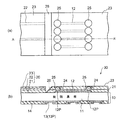
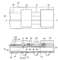
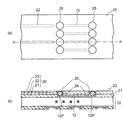
12(12P),13(13P)…配線層(パッド)、
14…ソルダレジスト層(保護膜/絶縁層)、
20…光導波路基板、
21,23…クラッド層、
22…コア層、
24,25…導体部分(導通ビア)、
26…反射ミラー、
30…光導波路積層配線基板(パッケージ)、
40,43…実装される部品、
41…光出射面(もしくは光入射面)、
42,44…電極端子、
VH1,VH2…ビアホール(開口されたビア)。
Claims (7)
- 接続用のパッドを有する配線基板と、
前記配線基板の上に形成され、前記パッドに到達する第1のビアホールを備えた第1クラッド層と、
前記ビアホールを充填して形成され、前記第1クラッド層の面から突出して半球状に広がる突出部を有する第1の導体部分と、
前記第1クラッド層上の、前記第1の導体部分が配置された層間接続領域を除く領域に形成されたコア層と、
前記第1クラッド層、前記コア層及び前記第1の導体部分を覆って形成された第2クラッド層と、
前記第2クラッド層に形成され、前記第2クラッド層に埋設された前記第1の導体部分の前記半球状の部分に到達する第2のビアホールと、
前記第2のビアホールに充填され、前記第2クラッド層の表面と同じ面に露出して形成され、前記第1の導体部分の突出部に電気的に接続された第2の導体部分とを含むことを特徴とする光導波路積層配線基板。 - 接続用のパッドを有する配線基板と、
前記配線基板の上に形成され、前記パッドに到達する第1のビアホールを備えた第1クラッド層と、
前記ビアホールを充填して形成され、前記第1クラッド層の面から突出して半球状に広がる突出部を有する第1の導体部分と、
前記第1クラッド層の上の、前記第1の導体部分が配置された層間接続領域を除く領域に形成されたコア層と、
前記第1クラッド層、前記コア層及び前記第1の導体部分を覆って形成された第2クラッド層と、
前記第2クラッド層に形成され、前記第2クラッド層に埋設された前記第1の導体部分の前記半球状の部分に到達する第2のビアホールと、
前記第2のビアホールに充填され、前記第2クラッド層の表面と同じ面に露出して形成され、前記第1の導体部分の突出部に電気的に接続された第2の導体部分と、
前記第1クラッド層、前記コア層及び前記第2クラッド層からなる光導波路基板に形成された反射ミラーと、
前記第2の導体部分に接続された状態で前記第2クラッド層の上に実装され、前記反射ミラーの上に光出射面又は光入射面が配置された光学部品とを有することを特徴とする実装構造。 - 接続用のパッドを有した配線基板を用意する工程と、
前記配線基板の前記パッドが形成されている側の面に、第1クラッド層を形成後、該第1クラッド層に、前記パッドに達する第1のビアホールを形成する工程と、
前記第1のビアホールを導電性材料で充填して、前記第1クラッド層の面から突出して半球状に広がる突出部を有する第1の導体部分を形成する工程と、
前記第1クラッド層上の、前記第1の導体部分が配置された層間接続領域を除く領域に、コア層をパターニング形成する工程と、
前記第1クラッド層、前記コア層及び前記第1の導体部分を覆うように第2クラッド層を形成する工程と、
前記第2クラッド層に埋設された前記第1の導体部分の前記半球状の部分に到達する第2のビアホールを、前記第2クラッド層に形成する工程と、
前記第2のビアホールを導電性材料で充填して、前記第2クラッド層の表面と同じ面に露出する第2の導体部分を形成する工程とを含むことを特徴とする光導波路積層配線基板の製造方法。 - 前記第1クラッド層及び第2クラッド層の材料としてそれぞれ紫外線硬化型の樹脂を使用し、該樹脂を用いて形成された各クラッド層をパターニングしてそれぞれ前記第1、第2のビアホールを形成することを特徴とする請求項3に記載の光導波路積層配線基板の製造方法。
- 前記紫外線硬化型の樹脂を用いて形成された各クラッド層に対し、前記パターニングに代えて、レーザ加工によりそれぞれ前記第1、第2のビアホールを形成することを特徴とする請求項4に記載の光導波路積層配線基板の製造方法。
- 前記第1の導体部分及び第2の導体部分を、それぞれ無電解めっき又は電解めっきにより形成することを特徴とする請求項3乃至5のいずれか一項に記載の光導波路積層配線基板の製造方法。
- 前記第2の導体部分を形成する工程の後に、前記第1クラッド層、コア層及び第2クラッド層からなる光導波路基板の、実装される光学部品の光出射面又は光入射面に対向する位置に、反射ミラーを形成することを特徴とする請求項3乃至5のいずれか一項に記載の光導波路積層配線基板の製造方法。
Priority Applications (3)
| Application Number | Priority Date | Filing Date | Title |
|---|---|---|---|
| JP2009146398A JP5461897B2 (ja) | 2009-06-19 | 2009-06-19 | 光導波路積層配線基板及びその製造方法と実装構造 |
| US12/814,783 US8323878B2 (en) | 2009-06-19 | 2010-06-14 | Method of manufacturing optical waveguide laminated wiring board |
| US13/614,209 US8644656B2 (en) | 2009-06-19 | 2012-09-13 | Optical waveguide laminated wiring board |
Applications Claiming Priority (1)
| Application Number | Priority Date | Filing Date | Title |
|---|---|---|---|
| JP2009146398A JP5461897B2 (ja) | 2009-06-19 | 2009-06-19 | 光導波路積層配線基板及びその製造方法と実装構造 |
Publications (3)
| Publication Number | Publication Date |
|---|---|
| JP2011003774A JP2011003774A (ja) | 2011-01-06 |
| JP2011003774A5 JP2011003774A5 (ja) | 2012-06-28 |
| JP5461897B2 true JP5461897B2 (ja) | 2014-04-02 |
Family
ID=43354664
Family Applications (1)
| Application Number | Title | Priority Date | Filing Date |
|---|---|---|---|
| JP2009146398A Active JP5461897B2 (ja) | 2009-06-19 | 2009-06-19 | 光導波路積層配線基板及びその製造方法と実装構造 |
Country Status (2)
| Country | Link |
|---|---|
| US (2) | US8323878B2 (ja) |
| JP (1) | JP5461897B2 (ja) |
Families Citing this family (15)
| Publication number | Priority date | Publication date | Assignee | Title |
|---|---|---|---|---|
| US9185810B2 (en) * | 2006-06-06 | 2015-11-10 | Second Sight Medical Products, Inc. | Molded polymer comprising silicone and at least one metal trace and a process of manufacturing the same |
| US7750076B2 (en) * | 2006-06-07 | 2010-07-06 | Second Sight Medical Products, Inc. | Polymer comprising silicone and at least one metal trace |
| JP2013186310A (ja) | 2012-03-08 | 2013-09-19 | Shinko Electric Ind Co Ltd | 光電気複合基板及びその製造方法 |
| WO2014080709A1 (ja) | 2012-11-22 | 2014-05-30 | インターナショナル・ビジネス・マシーンズ・コーポレーション | 電気基板と光導波路の層とが積層される多層構造において、光導波路の層を貫通する電気連絡用ビア |
| JP6168598B2 (ja) * | 2013-08-21 | 2017-07-26 | 日東電工株式会社 | 光電気混載モジュール |
| JP6168602B2 (ja) * | 2013-10-31 | 2017-07-26 | 日東電工株式会社 | 光電気混載モジュール |
| JP6172679B2 (ja) * | 2014-06-26 | 2017-08-02 | インターナショナル・ビジネス・マシーンズ・コーポレーションInternational Business Machines Corporation | 光結合構造、半導体デバイス、マルチ・チップ・モジュールのための光インターコネクト構造、および光結合構造のための製造方法 |
| JP6395134B2 (ja) * | 2014-12-26 | 2018-09-26 | 新光電気工業株式会社 | 光導波路装置の製造方法及びレーザ加工装置 |
| JP2016156865A (ja) * | 2015-02-23 | 2016-09-01 | 京セラ株式会社 | 光回路基板の製造方法 |
| US9721812B2 (en) * | 2015-11-20 | 2017-08-01 | International Business Machines Corporation | Optical device with precoated underfill |
| JP2018105925A (ja) * | 2016-12-22 | 2018-07-05 | ルネサスエレクトロニクス株式会社 | 半導体装置およびその製造方法 |
| JP2018163918A (ja) * | 2017-03-24 | 2018-10-18 | 新光電気工業株式会社 | 配線基板及びその製造方法 |
| JP7244164B2 (ja) * | 2018-06-05 | 2023-03-22 | アサヒ飲料株式会社 | 混合茶飲料 |
| JP2020148830A (ja) * | 2019-03-11 | 2020-09-17 | ルネサスエレクトロニクス株式会社 | 半導体装置およびその製造方法 |
| JP2023008205A (ja) * | 2021-07-05 | 2023-01-19 | イビデン株式会社 | 配線基板 |
Family Cites Families (12)
| Publication number | Priority date | Publication date | Assignee | Title |
|---|---|---|---|---|
| JP3111590B2 (ja) * | 1992-02-14 | 2000-11-27 | 株式会社日立製作所 | 多層回路の製造方法 |
| JP3512225B2 (ja) * | 1994-02-28 | 2004-03-29 | 株式会社日立製作所 | 多層配線基板の製造方法 |
| JPH11330704A (ja) * | 1998-05-07 | 1999-11-30 | Nippon Avionics Co Ltd | プリント配線板およびプリント配線板の製造方法 |
| US6477284B1 (en) * | 1999-06-14 | 2002-11-05 | Nec Corporation | Photo-electric combined substrate, optical waveguide and manufacturing process therefor |
| JP4540275B2 (ja) | 2000-12-22 | 2010-09-08 | イビデン株式会社 | Icチップ実装用基板、および、icチップ実装用基板の製造方法 |
| JP3833132B2 (ja) * | 2002-03-25 | 2006-10-11 | キヤノン株式会社 | 光導波装置の製造方法 |
| US7499614B2 (en) * | 2003-10-24 | 2009-03-03 | International Business Machines Corporation | Passive alignment of VCSELs to waveguides in opto-electronic cards and printed circuit boards |
| JP4260650B2 (ja) * | 2004-02-26 | 2009-04-30 | 新光電気工業株式会社 | 光電気複合基板及びその製造方法 |
| JP4551321B2 (ja) * | 2005-07-21 | 2010-09-29 | 新光電気工業株式会社 | 電子部品実装構造及びその製造方法 |
| EP1967876A4 (en) * | 2005-12-27 | 2013-04-17 | Ibiden Co Ltd | OPTICAL AND ELECTRICAL COMPOSITE WIRING BOARD AND METHOD FOR MANUFACTURING THE SAME |
| TW200807047A (en) * | 2006-05-30 | 2008-02-01 | Sumitomo Bakelite Co | Substrate for mounting photonic device, optical circuit substrate, and photonic device mounting substrate |
| JP5155596B2 (ja) * | 2007-05-14 | 2013-03-06 | 新光電気工業株式会社 | 光電気混載基板の製造方法 |
-
2009
- 2009-06-19 JP JP2009146398A patent/JP5461897B2/ja active Active
-
2010
- 2010-06-14 US US12/814,783 patent/US8323878B2/en active Active
-
2012
- 2012-09-13 US US13/614,209 patent/US8644656B2/en active Active
Also Published As
| Publication number | Publication date |
|---|---|
| US8644656B2 (en) | 2014-02-04 |
| US20100323297A1 (en) | 2010-12-23 |
| US8323878B2 (en) | 2012-12-04 |
| US20130011096A1 (en) | 2013-01-10 |
| JP2011003774A (ja) | 2011-01-06 |
Similar Documents
| Publication | Publication Date | Title |
|---|---|---|
| JP5461897B2 (ja) | 光導波路積層配線基板及びその製造方法と実装構造 | |
| JP4260650B2 (ja) | 光電気複合基板及びその製造方法 | |
| US9201203B2 (en) | Photoelectric composite substrate and method of manufacturing the same | |
| JP5384819B2 (ja) | 光電気混載パッケージ、光電気混載モジュール | |
| JP6085526B2 (ja) | 光電気混載基板、及び光モジュール | |
| US9671575B2 (en) | Optical waveguide device and method of manufacturing the same | |
| JP2008241956A (ja) | 光電気混載パッケージ及びその製造方法、光素子付き光電気混載パッケージ、光電気混載モジュール | |
| US11378763B2 (en) | Optical waveguide having support member, optical waveguide mounting substrate and optical transceiver | |
| US7801399B2 (en) | Method of forming optical waveguide | |
| JP2004012803A (ja) | 光伝送用プリント板ユニット及び実装方法 | |
| JP6084027B2 (ja) | 光導波路装置及びその製造方法 | |
| US8737794B2 (en) | Two-layer optical waveguide and method of manufacturing the same | |
| JP6105254B2 (ja) | 光導波路積層配線基板、光モジュール及び光導波路積層配線基板の製造方法 | |
| US9244224B2 (en) | Optical waveguide device | |
| US11125954B2 (en) | Optical waveguide and optical waveguide device | |
| JP2014220330A (ja) | 光配線基板、光配線基板の製造方法、及び光モジュール | |
| JP7321907B2 (ja) | 光導波路、光導波路装置及び光導波路の製造方法 | |
| JP5302177B2 (ja) | 光導波路基板および光電気混載装置 | |
| JP4895957B2 (ja) | 光電気混載パッケージ、光電気混載モジュール | |
| US10928598B2 (en) | Optical waveguide mounting substrate and optical communication device | |
| JP2005338704A (ja) | 光結合機能付配線基板及びその製造方法と光結合システム | |
| JP2012088634A (ja) | 光導波路デバイス及びその製造方法 | |
| TW202209938A (zh) | 電路板結構及其製作方法 | |
| JP2023008205A (ja) | 配線基板 | |
| JP2009098223A (ja) | 光ビア付き異方導電性接着シート、光電気混載パッケージ及びその製造方法 |
Legal Events
| Date | Code | Title | Description |
|---|---|---|---|
| A521 | Written amendment |
Free format text: JAPANESE INTERMEDIATE CODE: A523 Effective date: 20120516 |
|
| A621 | Written request for application examination |
Free format text: JAPANESE INTERMEDIATE CODE: A621 Effective date: 20120516 |
|
| A977 | Report on retrieval |
Free format text: JAPANESE INTERMEDIATE CODE: A971007 Effective date: 20130424 |
|
| A131 | Notification of reasons for refusal |
Free format text: JAPANESE INTERMEDIATE CODE: A131 Effective date: 20130430 |
|
| A521 | Written amendment |
Free format text: JAPANESE INTERMEDIATE CODE: A523 Effective date: 20130611 |
|
| A131 | Notification of reasons for refusal |
Free format text: JAPANESE INTERMEDIATE CODE: A131 Effective date: 20131112 |
|
| A521 | Written amendment |
Free format text: JAPANESE INTERMEDIATE CODE: A523 Effective date: 20131121 |
|
| TRDD | Decision of grant or rejection written | ||
| A01 | Written decision to grant a patent or to grant a registration (utility model) |
Free format text: JAPANESE INTERMEDIATE CODE: A01 Effective date: 20140107 |
|
| A61 | First payment of annual fees (during grant procedure) |
Free format text: JAPANESE INTERMEDIATE CODE: A61 Effective date: 20140116 |
|
| R150 | Certificate of patent or registration of utility model |
Ref document number: 5461897 Country of ref document: JP Free format text: JAPANESE INTERMEDIATE CODE: R150 Free format text: JAPANESE INTERMEDIATE CODE: R150 |


