JP5345457B2 - Grinding equipment - Google Patents
Grinding equipment Download PDFInfo
- Publication number
- JP5345457B2 JP5345457B2 JP2009163032A JP2009163032A JP5345457B2 JP 5345457 B2 JP5345457 B2 JP 5345457B2 JP 2009163032 A JP2009163032 A JP 2009163032A JP 2009163032 A JP2009163032 A JP 2009163032A JP 5345457 B2 JP5345457 B2 JP 5345457B2
- Authority
- JP
- Japan
- Prior art keywords
- cleaning
- grinding
- cleaning liquid
- work
- holding
- Prior art date
- Legal status (The legal status is an assumption and is not a legal conclusion. Google has not performed a legal analysis and makes no representation as to the accuracy of the status listed.)
- Active
Links
Images


Description
本発明は、半導体ウェーハ等のワークを研削加工する研削装置に関するものである。 The present invention relates to a grinding apparatus for grinding a workpiece such as a semiconductor wafer.
半導体デバイス製造工程においては、略円板形状であるワークの表面に格子状に配列されたストリートと呼ばれる分割予定ラインによってワークを複数の矩形領域に区画し、これら矩形領域の各々に半導体回路を形成する。そして、半導体回路を形成したワークをストリートに沿って分離することによって個々の半導体チップを製造している。また、サファイヤ基板等の表面に窒化ガリウム系化合物半導体等を積層したワークも同様に、ストリートに沿って分離することで個々の発光ダイオード、レーザダイオード等の光デバイスとして製造されており、電子機器に広く利用されている。 In the semiconductor device manufacturing process, a work is divided into a plurality of rectangular areas by dividing lines called streets arranged in a grid on the surface of the work having a substantially disk shape, and a semiconductor circuit is formed in each of the rectangular areas. To do. Then, individual semiconductor chips are manufactured by separating the work on which the semiconductor circuit is formed along the streets. Similarly, workpieces with gallium nitride compound semiconductors laminated on the surface of sapphire substrates are also manufactured as optical devices such as individual light emitting diodes and laser diodes by separating along the streets. Widely used.
このように分離されるワークは、半導体チップの小型化および軽量化を図るため、ストリートに沿って分離するのに先立って裏面が研削され、所定の厚さに加工される。このワークの裏面研削は、通常、ワークの表面を保持手段によって保持し、例えばダイヤモンド砥粒等の砥石がレジンボンド等の好適なボンドで固着された研削工具を高速回転させつつこの研削工具を保持手段上のワークの裏面に対して押圧することによって行われる。具体的には、例えば特許文献1に開示された装置構成の研削装置が知られている。 In order to reduce the size and weight of the semiconductor chip, the workpiece separated in this way is ground at the back surface before being separated along the street and processed to a predetermined thickness. In this backside grinding of the workpiece, the surface of the workpiece is usually held by holding means, and this grinding tool is held while rotating a grinding tool to which a grinding stone such as diamond abrasive grains is fixed with a suitable bond such as a resin bond. This is done by pressing against the back side of the workpiece on the means. Specifically, for example, a grinding device having a device configuration disclosed in Patent Document 1 is known.
ところで、ワークの裏面研削は、上記したようにワークの表面(被保持面)を保持し、保持したワークの裏面を押圧しながら行うため、被保持面に異物が付着していると、研削加工時にワークが破損する等悪影響を与えるという問題があった。このため、研削装置に洗浄機構を設け、研削加工の前にワークの被保持面を洗浄するのが望ましい。ここで、研削装置はその筺体内部等に電装部品を実装しており、研削装置に洗浄機構を設ける場合、洗浄機構の周囲に洗浄液が飛散してしまうと、電装部品が浸水して故障する事態が生じ得る。 By the way, since the back surface grinding of the workpiece is performed while holding the surface of the workpiece (held surface) and pressing the back surface of the held workpiece as described above, if foreign matter adheres to the held surface, There was a problem that it sometimes had an adverse effect such as breakage of the workpiece. For this reason, it is desirable to provide a cleaning mechanism in the grinding apparatus to clean the held surface of the workpiece before grinding. Here, the grinding equipment has electrical components mounted inside its housing, etc., and when the grinding device is equipped with a cleaning mechanism, if the cleaning liquid scatters around the cleaning mechanism, the electrical components will submerge and break down. Can occur.
本発明は、上記に鑑みて為されたものであり、洗浄液の周囲への飛散を防止しつつ研削加工前のワークの被保持面を十分に洗浄することができる研削装置を提供することを目的とする。 The present invention has been made in view of the above, and an object of the present invention is to provide a grinding apparatus capable of sufficiently cleaning a held surface of a workpiece before grinding while preventing scattering of cleaning liquid around the object. And
上記した課題を解決し、目的を達成するために、本発明にかかる研削装置は、ワークの被保持面を保持する保持手段と、前記保持手段に保持された前記ワークを研削加工する研削手段と、前記ワークを位置決めする位置決め手段と、前記ワークを搬送面で保持しながら前記ワークを前記位置決め手段と前記保持手段との間で搬送する搬送手段とを備えた研削装置であって、前記搬送手段の搬送経路途中に配設され、前記ワークが前記保持手段に搬送される前に前記ワークの前記被保持面を洗浄する事前洗浄手段と、前記搬送手段の搬送経路途中の前記事前洗浄手段と前記位置決め手段との間に配設され、前記事前洗浄手段による洗浄時に発生する前記位置決め手段側への洗浄液の飛散を防止する洗浄液飛散防止手段と、を備え、前記事前洗浄手段は、内部に洗浄液が貯留され、前記搬送手段の前記搬送面に保持された前記ワークを前記洗浄液に水没させる水槽と、前記水槽内に配設され、前記ワークを前記水槽内の洗浄液に水没させた際に前記ワークの前記被保持面に接触するブラシと、前記ブラシを前記被保持面に沿って回転させるブラシ回転駆動機構と、を有し、前記洗浄液飛散防止手段は、前記洗浄液の飛散を遮断するシャッターと、前記洗浄液の飛散を遮断する作用位置と前記搬送手段の通過を許容する非作用位置とに前記シャッターを変位させるシャッター駆動機構と、前記非作用位置に変位した前記シャッターの前記搬送手段の通過近傍位置において、噴射口が前記搬送面に向かうように配されて配設されたノズルと、前記搬送手段が前記保持手段に前記ワークを搬送した後、前記事前洗浄手段側から前記位置決め手段側へ移動する際に、前記噴射口から前記搬送面に向けて気体を噴射させる気体噴射機構と、を有することを特徴とする。 In order to solve the above-described problems and achieve the object, a grinding apparatus according to the present invention includes a holding unit that holds a surface to be held of a workpiece, and a grinding unit that grinds the workpiece held by the holding unit. A grinding apparatus comprising: positioning means for positioning the workpiece; and conveying means for conveying the workpiece between the positioning means and the holding means while holding the workpiece on a conveyance surface, Pre-cleaning means for cleaning the held surface of the work before the work is transported to the holding means, and the pre-cleaning means in the middle of the transport path of the transport means. Cleaning liquid splash preventing means disposed between the positioning means and preventing the cleaning liquid from splashing toward the positioning means generated during cleaning by the preliminary cleaning means. The stage has a cleaning liquid stored therein, a water tank in which the work held on the transfer surface of the transfer means is submerged in the cleaning liquid, and is disposed in the water tank, and the work is submerged in the cleaning liquid in the water tank. And a brush rotation drive mechanism for rotating the brush along the held surface when the cleaning liquid is scattered, and the cleaning liquid splash preventing means is configured to splash the cleaning liquid. A shutter that shuts off the cleaning liquid, a shutter driving mechanism that displaces the shutter to a non-operating position that allows the transport means to pass, and a shutter driving mechanism that displaces the cleaning liquid, and the shutter that is displaced to the non-operating position. In a position near the passage of the conveying means, a nozzle arranged with an ejection port directed toward the conveying surface, and the conveying means conveys the workpiece to the holding means. After, when moving from said prewash section side to the positioning means side, characterized by having a a gas injection mechanism for injecting a gas toward the conveying surface from the ejection nozzle.
また、本発明にかかる研削装置は、上記発明において、前記水槽内に前記洗浄液を供給する供給口および前記水槽内の前記洗浄液を外部に排出する排出口が前記水槽の底部に形成されたことを特徴とする。 In the grinding device according to the present invention, in the above invention, a supply port for supplying the cleaning liquid into the water tank and a discharge port for discharging the cleaning liquid in the water tank to the outside are formed at the bottom of the water tank. Features.
本発明によれば、研削加工時に保持手段によって保持されるワークの被保持面を洗浄し、被保持面に付着している異物を除去することができる。またこの際、位置決め手段側への洗浄液の飛散を防止することができる。また、ワークを搬送する搬送手段が事前洗浄手段側から位置決め手段側へと移動する際、その搬送面に気体を吹き付けることができ、搬送面に付着した洗浄液を除去することができる。したがって、洗浄液の周囲への飛散、特に位置決め手段側への飛散を防止しつつ研削加工前のワークの被保持面を十分に洗浄することができるという効果を奏する。ここで、一般的な研削装置では、研削手段による研削加工時に水を用いるため、保持手段側については防止機能が確保された構成となっている。 According to the present invention, it is possible to clean the surface to be held of the work held by the holding means during the grinding process, and to remove foreign matters adhering to the surface to be held. At this time, it is possible to prevent the cleaning liquid from scattering to the positioning means side. Further, when the conveying means for conveying the workpiece moves from the pre-cleaning means side to the positioning means side, gas can be blown onto the conveying surface, and the cleaning liquid adhering to the conveying surface can be removed. Therefore, there is an effect that the surface to be held of the workpiece before grinding can be sufficiently cleaned while preventing the cleaning liquid from splashing around, particularly the positioning means side. Here, in a general grinding apparatus, since water is used during grinding by the grinding means, a prevention function is secured on the holding means side.
以下、本発明を実施するための形態である研削装置について図面を参照して説明する。 Hereinafter, a grinding device which is a form for carrying out the present invention is explained with reference to drawings.
まず、本実施の形態の研削装置について説明する。本実施の形態の研削装置は、ワークの被研削面を研削加工するためのものである。この研削装置が研削対象とするワークは、略円板形状を有し、例えば表面にストリートによって区画された複数のデバイスが形成されたものである。研削装置は、このワークの表面を被保持面として保持した状態で裏面を被研削面として研削加工する。また、本実施の形態の研削装置は、ワークの裏面を被吸着面として吸着した状態で、研削加工時に被保持面として保持される表面を被洗浄面として事前洗浄する。 First, the grinding apparatus of this embodiment will be described. The grinding apparatus according to the present embodiment is for grinding a surface to be ground of a workpiece. The workpiece to be ground by this grinding apparatus has a substantially disk shape, and is formed by, for example, a plurality of devices partitioned on the surface by streets. The grinding device grinds the back surface of the workpiece as the surface to be ground while holding the surface of the workpiece as the surface to be held. In addition, the grinding apparatus according to the present embodiment pre-cleans the surface that is held as the held surface during the grinding process with the back surface of the work as the attracted surface.
なお、ワークの具体例としては、特に限定されないが、例えば、シリコンウェーハやGaAs等の半導体ウェーハ、セラミック、ガラス、サファイア(Al2O3)系の無機材料基板、板状金属や樹脂等の延性材料、さらには、ミクロンオーダーからサブミクロンオーダーの平坦度(TTV:total thickness variation:ワークの被研削面を基準面として厚み方向に測定した高さの被研削面全面における最大値と最小値の差)が要求される各種加工材料が挙げられる。 Specific examples of the workpiece are not particularly limited. For example, ductility such as silicon wafer, semiconductor wafer such as GaAs, ceramic, glass, sapphire (Al 2 O 3 ) -based inorganic material substrate, plate metal, resin, etc. Material, and flatness on the order of micron to submicron (TTV: total thickness variation: the difference between the maximum and minimum values of the entire surface to be ground measured in the thickness direction with the surface to be ground of the workpiece as the reference surface ) Are required.
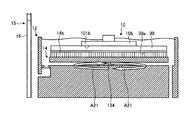
図1は、本実施の形態の研削装置1の構成例を示す斜視図である。また、図2は、研削装置1を構成する事前洗浄手段12および洗浄液飛散防止手段15の周辺を拡大して示す斜視図であり、図3は、事前洗浄手段12および洗浄液飛散防止手段15の構成を説明する一部断面図であり、図4は、事前洗浄手段12および洗浄液飛散防止手段15の動作に関する研削装置1の制御系の構成例を示すブロック図である。
FIG. 1 is a perspective view showing a configuration example of a grinding apparatus 1 according to the present embodiment. 2 is an enlarged perspective view showing the periphery of the pre-cleaning means 12 and the cleaning liquid
図1に示すように、研削装置1は、例えば、ハウジング2と、2つの研削手段3,4と、ターンテーブル5上に設置された例えば3つの保持手段6a〜6cと、カセット7,8と、位置決め手段9と、搬送手段としての搬入手段10と、搬出手段11と、洗浄手段18と、搬出入手段19と、事前洗浄手段12と、洗浄液飛散防止手段15と、制御手段20とを備えている。
As shown in FIG. 1, the grinding apparatus 1 includes, for example, a
研削手段3は、保持手段6bの保持面6sに直交する回転軸3aの下端に着脱自在に装着された研削砥石3bを有する研削ホイール3cをモータ3dによって回転させながら保持面6sに保持されたワークの被研削面(裏面)に押圧することによって、被研削面に対して研削加工(例えば、粗研削)を施すためのものである。研削手段4も同様に、保持手段6cの保持面6sに直交する回転軸4aの下端に着脱自在に装着された研削砥石4bを有する研削ホイール4cをモータ4dによって回転させながら保持面6sに保持されたワークの被研削面に押圧することによって、被研削面に対して研削加工(例えば、仕上げ研削)を施すためのものである。
The grinding means 3 is a work held on the
ここで、研削手段3,4は、それぞれ昇降送り手段31,41により昇降送り可能に設けられ、研削砥石3b,4bを有する研削ホイール3c,4cを保持手段6b,6c上のワークの被研削面に対して研削送り可能に構成されている。
Here, the grinding means 3 and 4 are provided so as to be moved up and down by the lifting and feeding means 31 and 41, respectively, and the grinding
ターンテーブル5上の3つの保持手段6a〜6cは、例えば120度の位相角で等間隔に配設されている。これら保持手段6a〜6cは、上面に真空チャックを備えたチャックテーブル構造のものであり、平坦に形成された保持面6sにワークの被保持面(表面)を真空吸着して保持する。また、これら保持手段6a〜6cは、研削加工時には、不図示の回転駆動機構によって水平面内で回転駆動される。
The three holding means 6a to 6c on the
ターンテーブル5は、ハウジング2の上面に水平面内で回転可能に設けられ、適宜タイミングで回転駆動される。そして、ターンテーブル5は、この回転によって、3つの保持手段6a〜6cを研削手段3による研削位置(図1中の保持手段6bの位置)、研削手段4による研削位置(図1中の保持手段6cの位置)および搬入搬出位置(図1中の保持手段6aの位置)に順次移動させる。
The
カセット7,8は、複数のスロットを有するワーク用の収容器である。一方のカセット7は、研削加工前のワークを収容し、他方のカセット8は、研削加工後のワークを収容する。位置決め手段9は、カセット7から取り出されたワークを仮置きし、その中心位置の位置決めを行うためのテーブルである。 The cassettes 7 and 8 are container for work having a plurality of slots. One cassette 7 accommodates the workpiece before grinding, and the other cassette 8 accommodates the workpiece after grinding. The positioning means 9 is a table for temporarily placing the work taken out from the cassette 7 and positioning its center position.
搬入手段10は、鉛直方向への昇降および自身の基端部を通過する鉛直線を中心軸とする回転を自在に行う搬送アーム10aを備え、この搬送アーム10aに、ワークを吸着保持する吸着パッド10bが取り付けられて構成されている。この搬入手段10は、位置決め手段9で位置決めされた研削加工前のワークの被吸着面(裏面)を吸着保持して事前洗浄手段12に搬入するとともに、この事前洗浄手段12によって被洗浄面(表面)が事前洗浄された研削加工前のワークを搬入搬出位置に位置する保持手段6aの保持面6sに搬入する。同様に、搬出手段11は、鉛直方向への昇降および自身の基端部を通過する鉛直線を中心軸とする回転を自在に行う搬送アーム11aを備え、この搬送アーム11aに、ワークを吸着保持する吸着パッド11bが取り付けられて構成されている。この搬出手段11は、搬入搬出位置に位置する保持手段6a上の研削加工後のワークを吸着保持し、洗浄手段18に搬出する。
The carry-in means 10 includes a
事前洗浄手段12は、研削加工前のワークの被洗浄面を保持手段6aに対する搬入前の位置で事前洗浄するものであり、位置決め手段9と搬入搬出位置に位置する保持手段6aとの間で搬送アーム10aの回動によって移動してワークを搬送する吸着パッド10bの図2中に矢印A1で示す搬送経路途中に配設される。この事前洗浄手段12は、上部に開口を有し、内部空間に例えば純水等の洗浄液が貯留される水槽13を備える。
The pre-cleaning means 12 pre-cleans the surface to be cleaned of the workpiece before grinding at a position before loading with respect to the holding means 6a, and is transported between the positioning means 9 and the holding means 6a positioned at the loading / unloading position. The
水槽13の底面には、図3に示すように、水槽13の内部空間と外部とを連通して水槽13の内部空間に洗浄液を供給する供給口131が形成されており、図3中に矢印A2で示すように、この供給口131から不図示の洗浄水供給機構によって水槽13の内部空間に洗浄液が供給される。また、水槽13の底面には、水槽13の内部空間と外部とを連通して水槽13の内部空間に貯留されている洗浄液を外部に排出する排出口132が形成されており、排出口132から排出された洗浄液は、図3中に矢印A3で示すように、水槽13の下方へ導かれて排出される。ここで、排出口132にはバルブ133が設けられており、洗浄液の供給時にはこのバルブ133を閉止した状態で供給口131から洗浄液が供給され、洗浄液の排出時には不図示の洗浄水排出機構によってバルブ133が開放されるようになっている。この水槽13において、搬送面101bを形成する吸着パッド10bに吸着保持されたワーク30は、図3中に矢印A11で示す方向に沿って吸着パッド10bが下降することで内部空間に貯留された洗浄液に水没される。
As shown in FIG. 3, a
また、事前洗浄手段12は、研削加工前のワークの被洗浄面を洗浄するためのブラシ14を備える。ブラシ14は、図2に示すように、ワークと略同等の面積を有する略円板形状の支持板14aにブラシ毛14bが放射状に植設されて構成される。このブラシ14は、図3中に矢印A12で示す方向に沿って水槽13の上方に移動した吸着パッド10bが矢印A11で示す方向に沿って下降し、この吸着パッド10bに吸着保持されたワーク30が洗浄液に水没された際に、ブラシ毛14bが被洗浄面に接触するように水槽13の内部に配設される。具体的には、ブラシ14は、水槽13の底部に設けられた水平面に直交する回転軸134の上端に取り付けられ、図4に示すブラシ回転機構121により、適宜タイミングで回転軸134を軸中心として水平面内で回転可能に構成される。
The pre-cleaning means 12 includes a
洗浄液飛散防止手段15は、図2に示すように、位置決め手段9と事前洗浄手段12との間に配設されたシャッター16からなる。このシャッター16の上面には、図4に示す気体噴射機構152によって適宜タイミングで気体を噴射する複数のノズル17が配設される。各ノズル17は、その噴射口が鉛直方向上方に向かうように配されて配列されており、図3中に矢印A12で示す方向に沿ってシャッター16の上方を通過した吸着パッド10b(詳細には吸着パッド10bの搬送面101b)に向けて気体を噴射可能な構成となっている。
As shown in FIG. 2, the cleaning liquid
ここで、研削手段3,4によるワークの研削加工時には適宜純水等の研削加工液が使用されるため、保持手段6a〜6cが設置されたターンテーブル5側(図1中に向かって事前洗浄手段12より奥側の領域)は防水性を備えた構成となっている。一方、カセット7,8や位置決め手段9、搬出入手段19等を備える図1中に向かって事前洗浄手段12より手前側の領域は水の使用が想定されておらず、防水機能が確保されていない。このため、この手前側の領域に対応するハウジング2の内部において電装部品を実装している場合、進入した洗浄液で電装部品が浸水してしまう。このような事態を防止するため、洗浄液飛散防止手段15は、ワークの被洗浄面を事前洗浄するために事前洗浄手段12が使用する洗浄液が位置決め手段9側へ侵入しないように洗浄液の飛散・遮断を防止する。
Here, since a grinding fluid such as pure water is appropriately used when the workpiece is ground by the grinding means 3 and 4, the
具体的には、シャッター16は、図4に示すシャッター駆動機構151により図3中に矢印A13で示す方向に沿って昇降移動し、その高さ位置(上面の位置)が図3中に一点鎖線で示すように水槽13の上端より上方に突出した作用位置と、図3中に実線で示すように作用位置から退避してシャッター16上方の搬入手段10の通過を許容する非作用位置とに変位可能に構成されている。作用位置は、高さ位置が水槽13の上端に対して十分高い位置に設定される。一方、非作用位置は、高さ位置が水槽13の上端と略同じ高さ位置に設定される。
Specifically, the
以上のように構成される洗浄液飛散防止手段15は、事前洗浄時には洗浄液の位置決め手段9側への飛散を防止する機能を果たし、吸着パッド10bの通過時には事前洗浄の際に吸着パッド10bの搬送面101bに付着した洗浄液を除去する機能を果たす。
The cleaning liquid splash prevention means 15 configured as described above functions to prevent the cleaning liquid from splashing toward the positioning means 9 at the time of preliminary cleaning, and when the
図1に戻る。洗浄手段18は、研削加工後のワークを洗浄し、研削された被研削面に付着している研削屑等のコンタミネーションを除去する。 Returning to FIG. The cleaning means 18 cleans the workpiece after grinding, and removes contamination such as grinding dust adhering to the ground surface to be ground.
搬出入手段19は、例えばU字型ハンドを備えるロボットアーム19aであり、ロボットアーム19aによってワークの被研削面を吸着保持して搬送する。具体的には、搬出入手段19は、研削加工前のワークをカセット7から位置決め手段9へ搬出するとともに、研削加工後のワークを洗浄手段18からカセット8へ搬入する。
The carry-in / out means 19 is, for example, a
制御手段20は、研削装置1の動作に必要な各種データを保持するメモリを内蔵したマイクロコンピュータ等で構成され、研削装置1を構成する各部の動作を制御して研削装置1を統括的に制御する。本実施の形態では、制御手段20は、搬入手段10の吸着パッド10bによって事前洗浄手段12に搬入された研削加工前のワークの被洗浄面を事前洗浄させるとともに、この事前洗浄手段12からの洗浄液の飛散を防止させるように事前洗浄手段12および洗浄液飛散防止手段15の動作を制御する。具体的には、図4に示すように、制御手段20は、ブラシ回転機構121を駆動して事前洗浄手段12の動作を制御するとともに、シャッター駆動機構151および気体噴射機構152を駆動して洗浄液飛散防止手段15の動作を制御する。
The control means 20 is composed of a microcomputer or the like with a built-in memory for holding various data necessary for the operation of the grinding apparatus 1, and controls the operation of each part constituting the grinding apparatus 1 to control the grinding apparatus 1 in an integrated manner. To do. In the present embodiment, the control means 20 pre-cleans the surface to be cleaned of the workpiece before grinding carried into the pre-cleaning means 12 by the
ここで、このように制御手段20によって制御される事前洗浄手段12および洗浄液飛散防止手段15の動作について説明する。図5−1および図5−2は、事前洗浄手段12および洗浄液飛散防止手段15の動作について説明する一部断面図である。
Here, the operations of the pre-cleaning means 12 and the cleaning liquid
図5−1に示すように、事前洗浄時には、水槽13の上方に搬入手段10の吸着パッド10bが移動する。そして、シャッター駆動機構151によってシャッター16の上面高さが作用位置まで上昇した後、吸着パッド10bが水槽13内に下降する。これにより、吸着パッド10b(搬送面101b)によって被吸着面が吸着保持された研削加工前のワーク30が水槽13の上部開口から挿入され、内部空間に貯留されている洗浄液に水没されてワーク30の被洗浄面30aがブラシ毛14bの先端と接触する。その後、ブラシ回転機構121により、ブラシ14が図5−1中に矢印A21で示すように回転軸134を軸中心として水平面内で回転する。これにより、ブラシ毛14bがワーク30の被洗浄面30aに沿って回転し、被洗浄面30aに付着している異物が除去される。またこの事前洗浄時、高さ位置が作用位置に位置したシャッター16が、洗浄液の位置決め手段9側への浸入を遮断する壁となり、事前洗浄に伴って水槽13から外部へ飛散した洗浄液の位置決め手段9側への飛散が防止される。
As shown in FIG. 5A, the
そして、事前洗浄を終えると吸着パッド10bが上昇し、その後、搬入搬出位置に位置する保持手段6a上に移動してワーク30を保持面6sに搬入する。また、吸着パッド10b(搬入手段10)は、ワーク30を保持面6sに搬入した後、新たな研削加工前のワークを搬入するために図5−2中に矢印A22で示す方向に沿って再度位置決め手段9上に移動するが、このときにシャッター16の上方を通過する。この吸着パッド10bの通過を妨げないよう、図5−1に示した事前洗浄の後、図5−2に示すように、シャッター16の高さ位置がシャッター駆動機構151によって非作用位置まで下降する。また、このようにシャッター16の上方を吸着パッド10bが通過する際、気体噴射機構152によってシャッター16の上面に配列された複数のノズル17がそれぞれ気体を噴射する。これにより、吸着パッド10bの搬送面101bに向けて気体が噴射され、事前洗浄の際に吸着パッド10bの搬送面101bに付着した洗浄液が除去される。
When the pre-cleaning is finished, the
つぎに、以上説明した研削装置1を用いたワークの研削加工について説明する。カセット7に収容された研削加工前のワークは、搬出入手段19のロボットアーム19aにより取り出されて位置決め手段9に搬出され、中心位置が位置決めされる。その後、ワークは、搬入手段10の吸着パッド10bにより被吸着面が吸着保持されて事前洗浄手段12に搬入され、この事前洗浄手段によって被洗浄面が事前洗浄される。
Next, workpiece grinding using the grinding apparatus 1 described above will be described. The workpiece before grinding stored in the cassette 7 is taken out by the
事前洗浄手段12での事前洗浄を終えたワークは、搬入手段10の吸着パッド10bによって搬入搬出位置に位置する保持手段6a上に搬入され、保持面6sによって、事前洗浄された被洗浄面であるワークの表面が被保持面として保持される。このようにしてワークを保持した搬入搬出位置の保持手段6aは、ターンテーブル5の回転とともに研削手段3による研削位置に移動し、ワークの被研削面を研削砥石3bによる研削加工に供する。また、これと同時に、保持手段6bに保持されて研削手段3による研削位置での研削加工を終えたワークが研削手段4による研削位置に移動し、ワークの被研削面を研削砥石4bによる研削加工に供する。そしてこの間に、搬入手段10により、次のワークが搬入搬出位置に移動した保持手段6c上に搬入保持される。
The workpiece that has been pre-cleaned by the pre-cleaning means 12 is a surface to be cleaned that is loaded onto the holding means 6a positioned at the loading / unloading position by the
つづいて、研削手段3による研削加工を終えたワークを保持した保持手段6aが、ターンテーブル5の回転とともに研削手段4による研削位置に移動し、ワークの被研削面を研削砥石4bによる研削加工に供する。また、これと同時に保持手段6cに搬入保持された次のワークが研削手段3による研削位置に移動し、ワークの被研削面を研削砥石3bによる研削加工に供する。そしてこの間に、研削手段4による研削加工を終えたワークを保持した保持手段6bが搬入搬出位置に移動する。
Subsequently, the holding means 6a that holds the workpiece that has been ground by the grinding means 3 moves to a grinding position by the grinding means 4 along with the rotation of the
ここで、研削加工を終えた搬入搬出位置のワークは、搬出手段11の吸着パッド11bにより吸着保持されて洗浄手段18に搬出される。洗浄手段18に搬出されたワークは、洗浄手段18にて被研削面が洗浄された後、搬出入手段19のロボットアーム19aによって把持されてカセット8に搬出され、カセット8内に収容される。また、上記の研削加工後のワークの搬出の後、保持手段6b上には、搬入手段10によって次のワークが搬入保持される。
Here, the workpiece at the loading / unloading position after finishing the grinding is sucked and held by the
その後、研削手段4による研削加工を終えたワークを保持した保持手段6aが、ターンテーブル5の回転とともに搬入搬出位置に移動する。また、これと同時に、保持手段6cに保持されて研削手段3による研削位置での研削加工を終えたワークが研削手段4による研削位置に移動し、ワークの被研削面を研削砥石4bによる研削加工に供する。また、保持手段6bに搬入保持されたワークが研削手段3による研削位置に移動し、ワークの被研削面を研削砥石3bによる研削加工に供する。以上の動作が、カセット7に収容された各ワークに対して繰り返される。
Thereafter, the holding means 6 a holding the workpiece that has been ground by the grinding means 4 moves to the carry-in / carry-out position as the
以上説明したように、本実施の形態によれば、事前洗浄手段12によって、研削加工時に保持手段6a〜6cが被保持面として保持するワークの表面を研削加工の前に事前洗浄することができる。またこのとき、洗浄液飛散防止手段15によって、洗浄液の位置決め手段9側への飛散を防止することができる。したがって、洗浄液の周囲への飛散、特に位置決め手段9側への飛散を防止しつつ研削加工前のワークの被保持面を十分に洗浄することができるという効果を奏する。さらに、吸着パッド10b(搬入手段10)が洗浄液飛散防止手段15の上方を通過して事前洗浄手段12側から位置決め手段9側へ移動する際、吸着パッド10b(詳細には吸着パッド10bの搬送面101b)に気体を吹き付けて事前洗浄時に搬送面101bに付着した洗浄液を除去することができる。したがって、位置決め手段9側に対する洗浄液の飛散・侵入防止効果を高めることができる。
As described above, according to the present embodiment, the
また、事前洗浄手段12において、水槽13の底面に形成された供給口131によって水槽13の底面側から水槽13の内部空間に洗浄液を供給し、水槽13の底面側から水槽13の内部空間の洗浄液を排出できるので、水槽13に対して洗浄液を供給し、排出する際に位置決め手段9側へ洗浄水が飛散・侵入するといった事態が生じない。したがって、位置決め手段9側に対する洗浄液の飛散・侵入防止効果をより一層高めることができる。
Further, in the pre-cleaning means 12, the cleaning liquid is supplied from the bottom surface side of the
以上のように、本発明の研削装置は、洗浄液の周囲への飛散を防止しつつ研削加工前のワークの被保持面を十分に洗浄するのに適している。 As described above, the grinding apparatus of the present invention is suitable for sufficiently cleaning the surface to be held of the workpiece before grinding while preventing the cleaning liquid from being scattered around.
1 研削装置
3,4 研削手段
5 ターンテーブル
6a〜6c 保持手段
9 位置決め手段
10 搬入手段
10a 搬送アーム
10b 吸着パッド
11 搬出手段
12 事前洗浄手段
13 水槽
14 ブラシ
121 ブラシ回転機構
15 洗浄液飛散防止手段
16 シャッター
17 ノズル
151 シャッター駆動機構
152 気体噴射機構
18 洗浄手段
19 搬出入手段
20 制御手段
DESCRIPTION OF SYMBOLS 1
Claims (2)
前記搬送手段の搬送経路途中に配設され、前記ワークが前記保持手段に搬送される前に前記ワークの前記被保持面を洗浄する事前洗浄手段と、
前記搬送手段の搬送経路途中の前記事前洗浄手段と前記位置決め手段との間に配設され、前記事前洗浄手段による洗浄時に発生する前記位置決め手段側への洗浄液の飛散を防止する洗浄液飛散防止手段と、
を備え、
前記事前洗浄手段は、
内部に洗浄液が貯留され、前記搬送手段の前記搬送面に保持された前記ワークを前記洗浄液に水没させる水槽と、
前記水槽内に配設され、前記ワークを前記水槽内の洗浄液に水没させた際に前記ワークの前記被保持面に接触するブラシと、
前記ブラシを前記被保持面に沿って回転させるブラシ回転駆動機構と、
を有し、
前記洗浄液飛散防止手段は、
前記洗浄液の飛散を遮断するシャッターと、
前記洗浄液の飛散を遮断する作用位置と前記搬送手段の通過を許容する非作用位置とに前記シャッターを変位させるシャッター駆動機構と、
前記非作用位置に変位した前記シャッターの前記搬送手段の通過近傍位置において、噴射口が前記搬送面に向かうように配されて配設されたノズルと、
前記搬送手段が前記保持手段に前記ワークを搬送した後、前記事前洗浄手段側から前記位置決め手段側へ移動する際に、前記噴射口から前記搬送面に向けて気体を噴射させる気体噴射機構と、
を有することを特徴とする研削装置。 A holding means for holding a surface to be held of the work; a grinding means for grinding the work held by the holding means; a positioning means for positioning the work; and holding the work on the transport surface while holding the work. A grinding apparatus comprising a conveying means for conveying between the positioning means and the holding means,
A pre-cleaning unit disposed in the transfer path of the transfer unit and cleaning the held surface of the work before the work is transferred to the holding unit;
Cleaning liquid splash prevention that is disposed between the pre-cleaning means and the positioning means in the middle of the transport path of the transport means and prevents the cleaning liquid from splashing toward the positioning means when cleaning is performed by the pre-cleaning means. Means,
With
The pre-cleaning means is
A water tank in which the cleaning liquid is stored and the work held on the transfer surface of the transfer means is submerged in the cleaning liquid,
A brush disposed in the water tank and in contact with the held surface of the work when the work is submerged in a cleaning liquid in the water tank;
A brush rotation drive mechanism for rotating the brush along the held surface;
Have
The cleaning liquid splash preventing means is
A shutter that blocks splashing of the cleaning liquid;
A shutter drive mechanism for displacing the shutter to an operating position that blocks the scattering of the cleaning liquid and a non-operating position that allows passage of the conveying means;
A nozzle disposed in a position near the passage of the conveying means of the shutter displaced to the non-operating position so that an injection port faces the conveying surface;
A gas injection mechanism for injecting gas from the injection port toward the transfer surface when the transfer unit moves from the pre-cleaning unit side to the positioning unit side after transferring the workpiece to the holding unit; ,
A grinding apparatus comprising:
Priority Applications (1)
| Application Number | Priority Date | Filing Date | Title |
|---|---|---|---|
| JP2009163032A JP5345457B2 (en) | 2009-07-09 | 2009-07-09 | Grinding equipment |
Applications Claiming Priority (1)
| Application Number | Priority Date | Filing Date | Title |
|---|---|---|---|
| JP2009163032A JP5345457B2 (en) | 2009-07-09 | 2009-07-09 | Grinding equipment |
Publications (2)
| Publication Number | Publication Date |
|---|---|
| JP2011018802A JP2011018802A (en) | 2011-01-27 |
| JP5345457B2 true JP5345457B2 (en) | 2013-11-20 |
Family
ID=43596368
Family Applications (1)
| Application Number | Title | Priority Date | Filing Date |
|---|---|---|---|
| JP2009163032A Active JP5345457B2 (en) | 2009-07-09 | 2009-07-09 | Grinding equipment |
Country Status (1)
| Country | Link |
|---|---|
| JP (1) | JP5345457B2 (en) |
Families Citing this family (5)
| Publication number | Priority date | Publication date | Assignee | Title |
|---|---|---|---|---|
| KR20140012053A (en) | 2011-01-31 | 2014-01-29 | 아사히 가라스 가부시키가이샤 | Method for producing silica glass body containing titania, and silica glass body containing titania |
| JP6335596B2 (en) * | 2014-04-07 | 2018-05-30 | 株式会社ディスコ | Grinding equipment |
| JP2017228680A (en) * | 2016-06-23 | 2017-12-28 | 株式会社ディスコ | Grinding device |
| JP7018452B2 (en) * | 2017-11-22 | 2022-02-10 | 東京エレクトロン株式会社 | Board processing system, board processing method and computer storage medium |
| JP2020131367A (en) * | 2019-02-20 | 2020-08-31 | 株式会社ディスコ | Grinding apparatus |
Family Cites Families (10)
| Publication number | Priority date | Publication date | Assignee | Title |
|---|---|---|---|---|
| JP3201119B2 (en) * | 1994-01-12 | 2001-08-20 | 松下電器産業株式会社 | Semiconductor laser device |
| JPH09190991A (en) * | 1996-01-11 | 1997-07-22 | Miyagi Oki Denki Kk | Brush scrub cleaning method and equipment |
| JPH09223680A (en) * | 1996-02-16 | 1997-08-26 | Disco Abrasive Syst Ltd | Polishing apparatus with etching function |
| JPH09283597A (en) * | 1996-04-12 | 1997-10-31 | Reniasu Techno:Kk | End effector cleaner and semiconductor substrate conveyer |
| JP3894514B2 (en) * | 1997-04-04 | 2007-03-22 | 株式会社ディスコ | Polishing equipment |
| JP4089837B2 (en) * | 1997-07-10 | 2008-05-28 | 株式会社ディスコ | Spinner device |
| JP2000015570A (en) * | 1998-07-02 | 2000-01-18 | Disco Abrasive Syst Ltd | Grinder |
| JP2002005097A (en) * | 2000-06-22 | 2002-01-09 | Ebara Corp | Vibration prevention system for vertical shaft type pump |
| JP2002016124A (en) * | 2000-06-28 | 2002-01-18 | Sony Corp | Wafer transporting arm mechanism |
| JP2007036152A (en) * | 2005-07-29 | 2007-02-08 | Tokyo Seimitsu Co Ltd | Wafer cleaning/drying method and wafer cleaning/drying equipment |
-
2009
- 2009-07-09 JP JP2009163032A patent/JP5345457B2/en active Active
Also Published As
| Publication number | Publication date |
|---|---|
| JP2011018802A (en) | 2011-01-27 |
Similar Documents
| Publication | Publication Date | Title |
|---|---|---|
| JP4790322B2 (en) | Processing apparatus and processing method | |
| CN107887313B (en) | Processing device | |
| KR20190003345A (en) | Wafer producing apparatus | |
| JP2018086692A (en) | Grinder | |
| JP5669518B2 (en) | Wafer transfer mechanism | |
| JP5345457B2 (en) | Grinding equipment | |
| TWI823988B (en) | polishing pad | |
| JP6162568B2 (en) | Grinding apparatus and wafer unloading method | |
| JP5731158B2 (en) | Processing equipment | |
| JP5350818B2 (en) | Grinding equipment | |
| JP2011003611A (en) | Grinding method and grinding device for wafer | |
| JP5837367B2 (en) | Grinding equipment | |
| JP2009113145A (en) | Chuck table mechanism of polishing device | |
| JP2006054388A (en) | Workpiece-conveying equipment, spinner-cleaning equipment, grinder, workpiece-conveying method | |
| KR20210056898A (en) | Holding surface cleaning apparatus | |
| JP5225733B2 (en) | Grinding equipment | |
| JP2011031359A (en) | Polishing tool, polishing device, and polishing machining method | |
| TW202208079A (en) | Workpiece cleaning method having a removing step for removing the cleaning liquid attached on the lower surface side of the workpiece | |
| JP2003273055A (en) | Spinner-cleaning unit | |
| JP2011040603A (en) | Processing method and grinding apparatus of wafer | |
| TW202216365A (en) | Polishing apparatus and polishing method | |
| KR20070017256A (en) | Spinner for cleaning wafer grinded | |
| TW202221785A (en) | Grinding apparatus | |
| JP2023171983A (en) | Grinding device | |
| JP2003243333A (en) | Spray tip and cleaning device |
Legal Events
| Date | Code | Title | Description |
|---|---|---|---|
| A621 | Written request for application examination |
Free format text: JAPANESE INTERMEDIATE CODE: A621 Effective date: 20120612 |
|
| A977 | Report on retrieval |
Free format text: JAPANESE INTERMEDIATE CODE: A971007 Effective date: 20130724 |
|
| TRDD | Decision of grant or rejection written | ||
| A01 | Written decision to grant a patent or to grant a registration (utility model) |
Free format text: JAPANESE INTERMEDIATE CODE: A01 Effective date: 20130730 |
|
| A61 | First payment of annual fees (during grant procedure) |
Free format text: JAPANESE INTERMEDIATE CODE: A61 Effective date: 20130814 |
|
| R150 | Certificate of patent or registration of utility model |
Free format text: JAPANESE INTERMEDIATE CODE: R150 Ref document number: 5345457 Country of ref document: JP Free format text: JAPANESE INTERMEDIATE CODE: R150 |
|
| R250 | Receipt of annual fees |
Free format text: JAPANESE INTERMEDIATE CODE: R250 |
|
| R250 | Receipt of annual fees |
Free format text: JAPANESE INTERMEDIATE CODE: R250 |
|
| R250 | Receipt of annual fees |
Free format text: JAPANESE INTERMEDIATE CODE: R250 |
|
| R250 | Receipt of annual fees |
Free format text: JAPANESE INTERMEDIATE CODE: R250 |
|
| R250 | Receipt of annual fees |
Free format text: JAPANESE INTERMEDIATE CODE: R250 |
|
| R250 | Receipt of annual fees |
Free format text: JAPANESE INTERMEDIATE CODE: R250 |
|
| R250 | Receipt of annual fees |
Free format text: JAPANESE INTERMEDIATE CODE: R250 |
|
| R250 | Receipt of annual fees |
Free format text: JAPANESE INTERMEDIATE CODE: R250 |