JP5329367B2 - Rotation angle detection device, manufacturing method thereof, and throttle control device - Google Patents
Rotation angle detection device, manufacturing method thereof, and throttle control device Download PDFInfo
- Publication number
- JP5329367B2 JP5329367B2 JP2009245296A JP2009245296A JP5329367B2 JP 5329367 B2 JP5329367 B2 JP 5329367B2 JP 2009245296 A JP2009245296 A JP 2009245296A JP 2009245296 A JP2009245296 A JP 2009245296A JP 5329367 B2 JP5329367 B2 JP 5329367B2
- Authority
- JP
- Japan
- Prior art keywords
- rotation angle
- magnetic detection
- resin
- foamed resin
- mold
- Prior art date
- Legal status (The legal status is an assumption and is not a legal conclusion. Google has not performed a legal analysis and makes no representation as to the accuracy of the status listed.)
- Expired - Fee Related
Links
Images


Description
本発明は、回転角検出装置及びその製造方法並びにスロットル制御装置に関する。 The present invention relates to a rotation angle detection device, a manufacturing method thereof, and a throttle control device.
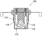
回転側部材の回転にともなう磁気の変化を検出する磁気検出部材を備える回転角検出装置に関する従来例を述べる。図13は回転角検出装置を示す断面図である。
図13に示すように、回転角検出装置166は、ケーシング172と、ケーシング172内に収容された磁気検出部材170と、磁気検出部材170を保持しかつケーシング172の開口端部を封止するホルダ174と、ケーシング172とホルダ174との間の内部空間に充填されたポッティング樹脂176とを備えて構成されている(例えば、特許文献1参照)。
A conventional example relating to a rotation angle detection device including a magnetic detection member that detects a change in magnetism associated with the rotation of the rotation side member will be described. FIG. 13 is a cross-sectional view showing a rotation angle detection device.
As shown in FIG. 13, the rotation
前記従来例の回転角検出装置166によると、磁気検出部材170を保持するための、ケーシング172、ホルダ174及びポッティング樹脂176が必要となる。したがって、部品点数が多くなり、コストアップを余儀なくされるという問題があった。
本発明が解決しようとする課題は、磁気検出部材の保持に要する部品点数を削減し、コストを低減することのできる回転角検出装置及びその製造方法並びにスロットル制御装置を提供することにある。
According to the conventional rotation
The problem to be solved by the present invention is to provide a rotation angle detecting device, a manufacturing method thereof, and a throttle control device capable of reducing the number of parts required for holding a magnetic detecting member and reducing the cost.
第1の発明は、回転側部材の回転にともなう磁気の変化を検出する磁気検出部材を備える回転角検出装置であって、磁気検出部材が発泡樹脂でモールドされたものである。したがって、磁気検出部材が該磁気検出部材をモールドした発泡樹脂で保持されるから、従来例(特許文献1参照)と比べて、磁気検出部材の保持に要する部品点数を削減し、コストを低減することができる。また、発泡樹脂は、断熱性に優れているため、磁気検出部材を温度変化等から良好に保護することができる。また、発泡樹脂は、溶融時の流動性が高いため、インサート成形時の注入樹脂の流動圧を低減することができる。したがって、インサート成形時に磁気検出部材にかかる樹脂の流動圧を低減することができ、該磁気検出部材の変形、損傷を防止することができる。 1st invention is a rotation angle detection apparatus provided with the magnetic detection member which detects the change of the magnetism accompanying rotation of a rotation side member, Comprising: A magnetic detection member is molded with foaming resin. Therefore, since the magnetic detection member is held by the foamed resin obtained by molding the magnetic detection member, the number of parts required to hold the magnetic detection member is reduced and the cost is reduced as compared with the conventional example (see Patent Document 1). be able to. In addition, since the foamed resin is excellent in heat insulation, the magnetic detection member can be well protected from temperature changes and the like. In addition, since the foamed resin has high fluidity at the time of melting, the flow pressure of the injected resin at the time of insert molding can be reduced. Therefore, the flow pressure of the resin applied to the magnetic detection member during insert molding can be reduced, and deformation and damage of the magnetic detection member can be prevented.
第2の発明は、第1の発明において、磁気検出部材は、磁気の変化を検出するセンシング部と、そのセンシング部の出力信号に基づいた演算を行って磁気の変化に応じた信号を出力する演算部とを備え、センシング部と演算部とがL字形状をなしている。したがって、センシング部と演算部とを備える磁気検出部材をコンパクト化することができる。 In a second aspect based on the first aspect, the magnetic detection member outputs a signal corresponding to the change in magnetism by performing a calculation based on a sensing unit that detects a change in magnetism and an output signal of the sensing unit. The sensing unit and the computing unit are L-shaped. Therefore, a magnetic detection member provided with a sensing part and a calculating part can be made compact.
第3の発明は、第2の発明において、磁気検出部材を2個使用し、両磁気検出部材がセンシング部を互いに重ねた状態で向かい合わせに配置されている。したがって、2個の磁気検出部材をコンパクトに配置することができる。 According to a third invention, in the second invention , two magnetic detection members are used, and the two magnetic detection members are arranged face to face in a state where the sensing portions are overlapped with each other. Therefore, the two magnetic detection members can be arranged in a compact manner.
第4の発明は、第3の発明において、両磁気検出部材で囲まれる樹脂モールド部に空洞部が形成されている。したがって、両磁気検出部材で囲まれる樹脂モールド部を均肉化することができる。 In a fourth aspect based on the third aspect , a cavity is formed in the resin mold portion surrounded by both magnetic detection members. Therefore, the resin mold part surrounded by both magnetic detection members can be made uniform.
第5の発明は、第1〜第4のいずれかの発明において、磁気検出部材のリード端子に取付ターミナルが連結され、リード端子と取付ターミナルとの連結部が発泡樹脂でモールドされている。したがって、磁気検出部材のリード端子と取付ターミナルとの連結部を発泡樹脂により保護することができる。 According to a fifth invention, in any one of the first to fourth inventions, the attachment terminal is connected to the lead terminal of the magnetic detection member, and the connecting portion between the lead terminal and the attachment terminal is molded with foamed resin. Therefore, the connecting portion between the lead terminal and the attachment terminal of the magnetic detection member can be protected by the foamed resin.
第6の発明は、第1〜第4のいずれかの発明において、磁気検出部材のリード端子の先端部が、発泡樹脂の樹脂モールド部から突出されている。したがって、磁気検出部材のリード端子に、発泡樹脂の樹脂モールド部から突出するターミナルを連結する必要がない。 According to a sixth aspect, in the first to fourth any one of the tip portions of the lead terminals of the magnetic detecting member is protruded from the resin mold portion of the foamed resin. Therefore, it is not necessary to connect the terminal protruding from the resin mold portion of the foamed resin to the lead terminal of the magnetic detection member.
第7の発明は、第1〜第5のいずれかの発明において、発泡樹脂が化学発泡樹脂である。したがって、一般的な射出成形機を用いて、磁気検出部材をモールドする発泡樹脂を射出成形することができる。 In a seventh aspect based on any one of the first to fifth aspects, the foamed resin is a chemical foamed resin. Therefore, the foamed resin for molding the magnetic detection member can be injection-molded using a general injection molding machine.
第8の発明は、第7の発明において、発泡樹脂が別の樹脂でモールドされ、発泡樹脂は別の樹脂の材料に発泡剤を加えた材料からなる。したがって、発泡樹脂と別の樹脂との基本的特性を同一化することができる。 In an eighth aspect based on the seventh aspect, the foamed resin is molded with another resin, and the foamed resin is made of a material obtained by adding a foaming agent to another resin material. Therefore, the basic characteristics of the foamed resin and another resin can be made identical.
第9の発明は、回転側部材の回転にともなう磁気の変化を検出する磁気検出部材を備える回転角検出装置の製造方法であって、磁気検出部材を発泡樹脂でインサート成形することによって、磁気検出部材を発泡樹脂でモールドすることができる。したがって、磁気検出部材が該磁気検出部材をモールドした発泡樹脂で保持されるから、従来例(特許文献1参照)と比べて、磁気検出部材の保持に要する部品点数を削減し、コストを低減することができる。 A ninth invention is a method of manufacturing a rotation angle detection device including a magnetic detection member for detecting a change in magnetism accompanying rotation of a rotation side member , and magnetic detection is performed by insert-molding the magnetic detection member with foamed resin. The member can be molded with foamed resin. Therefore, since the magnetic detection member is held by the foamed resin obtained by molding the magnetic detection member, the number of parts required to hold the magnetic detection member is reduced and the cost is reduced as compared with the conventional example (see Patent Document 1). be able to.
第10の発明は、第9の発明において、磁気検出部材は、磁気の変化を検出するセンシング部と、そのセンシング部の出力信号に基づいた演算を行って磁気の変化に応じた信号を出力する演算部とを備え、センシング部と演算部とがL字形状をなしている。したがって、センシング部と演算部とを備える磁気検出部材をコンパクト化することができる。さらに、磁気検出部材を2個使用し、両磁気検出部材がセンシング部を互いに重ねた状態で向かい合わせに配置された状態でインサート成形を行う。したがって、2個の磁気検出部材をコンパクトに配置することができる。 In a tenth aspect based on the ninth aspect, the magnetic detection member outputs a signal corresponding to the magnetic change by performing a calculation based on an output signal of the sensing unit that detects the magnetic change and the sensing unit. The sensing unit and the computing unit are L-shaped. Therefore, a magnetic detection member provided with a sensing part and a calculating part can be made compact. Furthermore, two magnetism detection members are used, and insert molding is performed in a state where both the magnetism detection members are arranged facing each other with the sensing portions being overlapped with each other. Therefore, the two magnetic detection members can be arranged in a compact manner.
第11の発明は、第10の発明において、金型に、両磁気検出部材で囲まれる部分内に介入する凸部を設け、金型の凸部が挿入された状態でインサート成形を行う。したがって、両磁気検出部材で囲まれる樹脂モールド部を均肉化することができる。これによって、インサート成形時の発泡樹脂(溶融樹脂)の流動によって両磁気検出部材に加わる応力を均等化し、その応力による両磁気検出部材の変形、損傷を防止することができる。 In an eleventh aspect based on the tenth aspect, the mold is provided with a convex portion that intervenes in a portion surrounded by both magnetic detection members, and insert molding is performed with the convex portion of the mold inserted. Therefore, the resin mold part surrounded by both magnetic detection members can be made uniform. This makes it possible to equalize the stress applied to both magnetic detection members by the flow of foamed resin (molten resin) during insert molding, and to prevent deformation and damage of both magnetic detection members due to the stress.
第12の発明は、第11の発明において、両磁気検出部材のリード端子に取付ターミナルが連結され、取付ターミナルを金型で支持した状態で両磁気検出部材とともにリード端子と取付ターミナルとの連結部をモールドするようにインサート成形を行う。したがって、インサート成形時の発泡樹脂(溶融樹脂)の流動による取付ターミナルの変形を防止することができる。また、両磁気検出部材とともにリード端子と取付ターミナルとの連結部を発泡樹脂により保護することができる。 In a twelfth aspect based on the eleventh aspect, the attachment terminal is connected to the lead terminals of both magnetic detection members, and the connection portion between the lead terminal and the attachment terminal together with both magnetic detection members in a state where the attachment terminal is supported by a mold. Insert molding is performed so as to mold. Therefore, it is possible to prevent the mounting terminal from being deformed by the flow of the foamed resin (molten resin) during the insert molding. Moreover, the connection part of a lead terminal and an attachment terminal can be protected with foaming resin with both magnetic detection members.
第13の発明は、第10〜第12のいずれかの発明において、両磁気検出部材のセンシング部を金型で支持した状態でインサート成形を行う。したがって、両磁気検出部材のセンシング部の位置精度を向上し、検出精度を向上することができる。 In a thirteenth invention according to any one of the tenth to twelfth inventions, insert molding is performed in a state where the sensing portions of both magnetic detection members are supported by a mold. Therefore, it is possible to improve the position accuracy of the sensing portions of both magnetic detection members and improve the detection accuracy.
第14の発明は、第10〜第13のいずれかの発明において、発泡樹脂を金型内に射出するに際し、発泡樹脂が両磁気検出部材のセンシング部から離れた位置から両磁気検出部材の演算部の長手方向に沿って充填される。したがって、発泡樹脂が両磁気検出部材のセンシング部から離れた位置から金型内に射出されることで、発泡樹脂(溶融樹脂)の流動によって両磁気検出部材のセンシング部に加わる応力を低減し、これによってセンシング部の変形、損傷を防止することができる。さらに、発泡樹脂(溶融樹脂)が両磁気検出部材の演算部の長手方向に沿って充填されることで、発泡樹脂(溶融樹脂)の流動によって両磁気検出部材の演算部に加わる応力を低減し、これによって両磁気検出部材の演算部の変形、損傷を防止することができる。 In a fourteenth invention according to any one of the tenth to thirteenth inventions, when the foamed resin is injected into the mold, the calculation of the two magnetic detection members is performed from the position where the foamed resin is separated from the sensing portion of the two magnetic detection members. It is filled along the longitudinal direction of the part. Therefore, the foamed resin is injected into the mold from a position away from the sensing part of both magnetic detection members, thereby reducing the stress applied to the sensing part of both magnetic detection members by the flow of the foamed resin (molten resin), As a result, deformation and damage of the sensing unit can be prevented. Furthermore, by filling the foamed resin (molten resin) along the longitudinal direction of the calculation part of both magnetic detection members, the stress applied to the calculation part of both magnetic detection members due to the flow of the foamed resin (molten resin) is reduced. As a result, deformation and damage of the arithmetic units of both magnetic detection members can be prevented.
第15の発明は、スロットルボデーの吸気通路を流れる吸入空気量をスロットルバルブの回転により調節するスロットル制御装置であって、スロットルバルブ側に回転側部材が設けられ、スロットルボデー側に第1〜第7のいずれかの発明の回転角検出装置が設けられ、回転角検出装置の磁気検出部材の出力に基づいてスロットルバルブの開度を検出する構成としたものである。したがって、磁気検出部材の保持に要する部品点数の削減によりコストが低減された回転角検出装置を備えたスロットル制御装置を提供することができる。
A fifteenth aspect of the invention is a throttle control device that adjusts the amount of intake air flowing through the intake passage of the throttle body by rotating the throttle valve, wherein a rotation side member is provided on the throttle valve side, and the first to first sides are provided on the throttle body side . The rotation angle detection device according to any one of the inventions is provided, and the opening degree of the throttle valve is detected based on the output of the magnetic detection member of the rotation angle detection device. Therefore, it is possible to provide a throttle control device including a rotation angle detection device whose cost is reduced by reducing the number of parts required for holding the magnetic detection member.
以下、本発明を実施するための形態について図面を用いて説明する。 Hereinafter, embodiments for carrying out the present invention will be described with reference to the drawings.
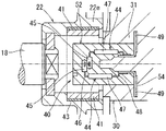
本発明の一実施例を説明する。本実施例は、自動車等の車両に搭載される電子制御式のスロットル制御装置におけるスロットルバルブの回転角すなわち開度を検出するスロットルポジションセンサとして用いられる回転角検出装置について例示する。説明の都合上、スロットル制御装置から説明する。図1はスロットル制御装置を示す断面図である。なお、スロットル制御装置については、図1における上下左右を基準として説明を行う。 An embodiment of the present invention will be described. This embodiment exemplifies a rotation angle detection device used as a throttle position sensor for detecting a rotation angle, that is, an opening degree of a throttle valve in an electronically controlled throttle control device mounted on a vehicle such as an automobile. For convenience of explanation, the throttle control device will be described first. FIG. 1 is a sectional view showing a throttle control device. The throttle control device will be described with reference to the vertical and horizontal directions in FIG.
図1に示すように、スロットル制御装置10は、スロットルボデー12を備えている。スロットルボデー12は、例えば樹脂製で、ボア壁部14とモータハウジング部17とを一体に有している。ボア壁部14は、図1において紙面表裏方向に延びる中空円筒状に形成されている。ボア壁部14内に、吸気通路としてのボア13が形成されている。ボア壁部14の上流側がエアクリーナ(図示省略)と接続され、その下流側がインテークマニホールド(図示省略)と接続される。また、ボア壁部14には、ボア13を径方向すなわち左右方向に横切る金属製のスロットルシャフト16が設けられている。スロットルシャフト16は、ボア壁部14の左右両側部に設けられた軸受部15に対してそれぞれ軸受(符号省略)を介して回転可能に支持されている。また、スロットルシャフト16には、円板状をなすバタフライバルブ式のスロットルバルブ18がスクリュ18sにより締着されている。スロットルバルブ18は、スロットルシャフト16と一体で回転することにより、ボア13を開閉する。
As shown in FIG. 1, the
前記スロットルシャフト16の右端部は、右側の軸受部15を貫通している。そして、スロットルシャフト16の右端部には、スロットルギヤ22が同軸上に回り止め状態で取付けられている。スロットルギヤ22は、例えば樹脂製で、二重円筒状をなす内筒部22eと外筒部22fとを有している。外筒部22fの外周部には、扇形のギヤ部22wが形成されている。また、スロットルギヤ22と、スロットルギヤ22に対面する前記スロットルボデー12の右側面との間には、コイルスプリングからなるバックスプリング26が設けられている。バックスプリング26は、スロットルギヤ22を常に閉じる方向へ付勢している。なお、バックスプリング26は、スロットルギヤ22の外筒部22f及び右側の軸受部15に嵌合されている。
The right end portion of the
前記スロットルボデー12のモータハウジング部17は、右方に開口しかつ前記スロットルシャフト16に平行する有底円筒状に形成されている。モータハウジング部17内には、例えばDCモータ等からなる駆動モータ28が設置されている。駆動モータ28は、自動車等のアクセルペダルの踏み込み量等に基づいて、エンジンコントロールユニットECU(図示省略)から出力される信号により出力回転軸(図示省略)が回転駆動される。また、駆動モータ28の出力回転軸は図1において右方に突出されており、その出力回転軸にピニオンギヤ29が設けられている。また、スロットルボデー12の右側面には、スロットルシャフト16と平行するカウンタシャフト23が設けられている。カウンタシャフト23には、カウンタギヤ24が回転可能に支持されている。カウンタギヤ24はギヤ径の異なる二つのギヤ部24a,24bを有している。大径側のギヤ部24aは、前記ピニオンギヤ29と噛合されている。また、小径側のギヤ部24bは、前記スロットルギヤ22(詳しくはギヤ部22w)と噛合されている。このため、駆動モータ28の回転駆動力は、ピニオンギヤ29、カウンタギヤ24、スロットルギヤ22を介してスロットルシャフト16に伝達される。これにより、スロットルバルブ18がボア13内で回転すなわち開閉されることで、ボア13を流れる吸入空気量が調節される。なお、ピニオンギヤ29、カウンタギヤ24、スロットルギヤ22により減速ギヤ機構が構成されている。
The
前記スロットルギヤ22の内筒部22eの内周部には、円筒状をなすヨーク43、及び、ヨーク43の内側に配置された一対の永久磁石41が一体的に設けられている(図2参照)。また、一対の永久磁石41は、例えばフェライト磁石からなり、相互間に略平行な磁界が発生するように平行着磁されている。また、ヨーク43は、磁性材料からなり、内筒部22eに埋設されている。なお、図2はスロットルギヤの周辺部を示す断面図である。
A
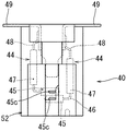
図1に示すように、前記スロットルボデー12の右側面には、前記減速ギヤ機構(ピニオンギヤ29、カウンタギヤ24及びスロットルギヤ22)等を覆うカバー30が取付けられている。カバー(以下、「センサカバー」という)30は、例えば樹脂製で、スロットルギヤ22の回転角すなわちスロットルバルブ18の開度を検出するための回転角検出装置40がインサート成形により一体化されている(図3参照)。なお、図3はセンサカバーを示す斜視図である。
As shown in FIG. 1, a
前記回転角検出装置40は、円柱状をなしており、その基部が前記センサカバー30の樹脂部であるカバー本体31にモールドすなわち埋設され、その先端部がカバー本体31の内側面に露出されている(図2及び図3参照)。回転角検出装置40の先端部は、前記スロットルギヤ22の内筒部22e内に対して、同軸状にかつ遊嵌状に挿入されている(図2参照)。したがって、回転角検出装置40は、スロットルギヤ22の永久磁石41及びヨーク43に対して非接触の関係をなしている。なお、スロットルギヤ22は本明細書でいう「回転側部材」に相当する。また、センサカバー30は本明細書でいう「固定側部材」に相当する。
The rotation
次に、回転角検出装置40を説明する。図4は回転角検出装置を示す正面図、図5は同じく平面図、図6は同じく平断面図である。なお、説明の都合上、回転角検出装置40については、先端部側(図5及び図6において下側)を前側とし、基部側(図5及び図6において上側)を後側として説明を行う。
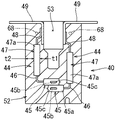
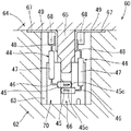
図6に示すように、回転角検出装置40は、2個の磁気検出部材44と、両磁気検出部材44をモールドすなわち埋設した円柱状の樹脂モールド部52とを備えている。また、回転角検出装置40は、前記スロットルギヤ22(図2参照)の回転にともなう磁気の変化を検出するもので、フェイルセーフを考慮して磁気検出部材44を2個使用し、仮にどちらかの磁気検出部材44が故障したとしても残りの磁気検出部材44で検出機能を確保できるように構成されている。
Next, the rotation
As shown in FIG. 6, the rotation
図6に示すように、磁気検出部材44は、例えばMR素子と呼ばれる磁気抵抗素子を備えたセンサICであって、センシング部45に複数の連結端子46を介して演算部47が接続されている。センシング部45は、樹脂製の直方体状のピース45aに磁気抵抗素子からなるチップ45bを内蔵している。また、演算部47は、樹脂製の直方体状のピース47aに図示しない半導体集積回路(IC)を内蔵している。センシング部45と演算部47とは、センシング部45の短手方向の一端面と演算部47の長手方向の一端面との間に架設された複数の連結端子46によって電気的に接続されている。また、複数の連結端子46はL字状に折り曲げられている。これによって、センシング部45と演算部47とがL字形状をなしている。また、演算部47の長手方向の他端部(後端面)には、複数(例えば、3本)のリード端子48の一端部(基端部)が接続されている。なお、説明の都合上、磁気検出部材44において、センシング部45と演算部47とのなす内角側を内側といい、その外角側を外側という。また、演算部47の長手方向と同方向を磁気検出部材44の長手方向といい、演算部47の短手方向(図6において紙面表裏方向)と同方向を磁気検出部材44の幅方向という。
As shown in FIG. 6, the
前記センシング部45のチップ45bは、金属製の長細板状の支持板45c上の中央部に設置されている。支持板45cは、その長手方向をセンシング部45の幅方向(図6において紙面表裏方向)に向けた状態で前記ピース45aに埋設されている。支持板45cの長手方向の両端部は、ピース45aの幅方向の両側面から突片状に突出されている(図4及び図5参照)。また、センシング部45は、その板厚方向(図6において上下方向)の両側面が前記スロットルギヤ22の軸線に対して直角をなすように配置されるとともに、チップ45bが前記樹脂モールド部52の軸線上に配置されている。また、前記スロットルボデー12にセンサカバー30が取付けられた状態(図1参照)では、センシング部45のチップ45bが前記スロットルギヤ22の一対の永久磁石41の間においてスロットルシャフト16の軸線上に位置されるようになっている。これにより、センシング部45(詳しくはチップ45b)は、一対の永久磁石41の間に発生する磁気の変化すなわち磁界の方向を検出可能となっている。
The
前記演算部47(詳しくは半導体集積回路(IC))には、前記センシング部45によって検出された検出結果(出力信号)が連結端子46を介して出力される。演算部47は、センシング部45の出力信号に基づいた演算を行って磁界の方向に応じた信号を出力する。演算部47の出力した信号に基づいて、前記エンジンコントロールユニットECU(図示省略)が前記スロットルギヤ22の回転角すなわち前記スロットルバルブ18の開度を検出する。また、演算部47は、スロットルギヤ22の回転角に対応するリニアな電圧信号を出力できるようにプログラムされている。
A detection result (output signal) detected by the
図6に示すように、前記2個の磁気検出部材44は、左右方向に向かい合わせでかつ前記センシング部45を互いに前後(図6において上下)に重ねた状態に配置されている。両センシング部45のチップ45bは、前記樹脂モールド部52の軸線上において、対向する位置関係をもって配置されている。また、両センシング部45の支持板45cは、前後方向(図6において上下方向)に整列されている。また、両磁気検出部材44の演算部47は、左右方向に所定間隔を隔てて平行状に配置されている。
As shown in FIG. 6, the two
前記演算部47の各リード端子48は、基部と先端部とが段違い状をなすように折り曲げられている。これにより、リード端子48の先端部(図6において上端部)が内側に片寄せられている。各リード端子48の先端部の内側には、L型の取付ターミナル49の一方の片部(「基端部」という)がそれぞれ溶接等により接続されている。これとともに、両取付ターミナル49の他方の片部(「先端部」という)が樹脂モールド部52の後端部から相反方向すなわち外側方に向けて突出されている。
Each
前記樹脂モールド部52は、化学発泡樹脂により円柱状に形成されている。樹脂モールド部52には、前記両磁気検出部材44(センシング部45、各連結端子46、演算部47及び各リード端子48)とともに両磁気検出部材44の各リード端子48と各取付ターミナル49との接続部すなわち連結部がモールドすなわち埋設されている。また、両磁気検出部材44で囲まれる樹脂モールド部52には空洞部53が形成されている。空洞部53は、樹脂モールド部52の後端面(図6において上端面)に開口する凹所内に形成されている。これにより、両磁気検出部材44で囲まれる樹脂モールド部52(特に演算部47の内側の樹脂モールド部)が演算部47の長手方向(図6において上下方向)に均肉化されている。すなわち、両磁気検出部材44の演算部47の内側の樹脂モールド部52における左右方向の肉厚t1が前後方向に均等化されている。また、両磁気検出部材44の演算部47の外側の樹脂モールド部52における左右方向の肉厚t2が、演算部47の長手方向(前後方向)に均等化されている。また、樹脂モールド部52の肉厚t1と肉厚t2とは同等化されている。また、空洞部53には、その内壁面に両磁気検出部材44の取付ターミナル49の基端部の内側面が露出されている。
The
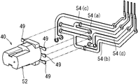
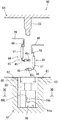
前記回転角検出装置40を前記センサカバー30にインサート成形により一体化する際(図3参照)には、各取付ターミナル49の先端部にそれぞれ配線ターミナル54の一端部(基端部)が溶接等により接続される(図7参照)。なお、図7において、配線ターミナル54(符号、(a)を付す)は電源用、配線ターミナル54(符号、(b)を付す)は接地用、配線ターミナル54(符号、(c)を付す)及び配線ターミナル54(符号、(d)を付す)はそれぞれ信号出力用となっている。なお、図7は配線ターミナル付き回転角検出装置を示す正面図、図8は配線ターミナルと回転角検出装置を分解して示す斜視図である。
When the rotation
前記配線ターミナル54が接続された回転角検出装置(「配線ターミナル付き回転角検出装置」という)40(図7参照)は、前記センサカバー30にインサート成形により一体化される(図3参照)。回転角検出装置40の基部はセンサカバー30の樹脂部であるカバー本体31にモールドすなわち埋設され、その先端部はカバー本体31の内側面に露出される。これとともに、カバー本体31には、回転角検出装置40の各取付ターミナル49と各配線ターミナル54との連結部、及び、各配線ターミナル54の先端部(端子部)54aを除いた大半の部分が埋設される。各配線ターミナル54の端子部54a(図7参照)は、カバー本体31に形成されたコネクタ部55(図3参照)内に露出される。コネクタ部55には、前記エンジンコントロールユニットECU側の外部コネクタ(図示省略)が接続されるようになっている。これにより、両磁気検出部材44の演算部47(図2参照)から出力された信号がエンジンコントロールユニットECUに入力される。なお、カバー本体31の内側面に露出された回転角検出装置40の樹脂モールド部52の先端部の外表面は、防湿材でコーティングするとよい。
A rotation angle detection device (referred to as “rotation angle detection device with a wiring terminal”) 40 (see FIG. 7) to which the
前記カバー本体31は、前記回転角検出装置40の樹脂モールド部(発泡樹脂)52とは別の樹脂で形成されている。すなわち、樹脂モールド部(発泡樹脂)52を形成する発泡樹脂は、カバー本体31を形成する別の樹脂の材料に発泡剤を加えた材料からなる。また、カバー本体(別の樹脂)31の材料としては、例えばポリブチレンテレフタレート(PBT)樹脂が使用される。
The
次に、前記回転角検出装置40の製造方法すなわち樹脂モールド部52の成形方法について説明する。なお、図9は回転角検出装置の製造に係る金型を示す断面図、図10は金型と磁気検出部材とを分解して示す断面図、図11は図10のXI−XI線矢視断面図である。
まず、磁気検出部材44を発泡樹脂でインサート成形する成形型いわゆる金型を説明する。図10に示すように、金型60は、下型62と上型64とから構成されている。下型62は、前記樹脂モールド部52(図4〜図6参照)の前端面及び外周面を成形する型で、有底円筒状の成形凹部63を備えている。また、上型64は、樹脂モールド部52の後端面及び空洞部53(図6参照)を成形する型で、下端面すなわち型合わせ面には凸部65が突出されている。
Next, a manufacturing method of the rotation
First, a so-called mold for insert-molding the
前記下型62の成形凹部63の両側壁(磁気検出部材44の幅方向(図10において紙面表裏方向)に対応する両側壁)には、L字状の位置決め部66が成形凹部63の軸線を中心として点対称状に設けられている(図11参照)。図10に示すように、位置決め部66は、両磁気検出部材44のセンシング部45の支持板45cの両端部と係合可能に形成されている。各位置決め部66は、前側のセンシング部45の支持板45cの端部の前側面(図10において下側面)に当接する水平状の第1段面66aと、両センシング部45の支持板45cの端部の一方(支持板45cの短手方向の一方)の側端面(図6において左端面)に当接する垂直状の第2段面66bと、磁気検出部材44の支持板45cの長手方向の端面に当接する垂直状の第3段面66cとを有している(図11参照)。また、下型62の上端面すなわち型合わせ面には、両取付ターミナル49の先端部を嵌合する凹部67が形成されている(図10参照)。
On both side walls of the
前記下型62の成形凹部63の一側壁(磁気検出部材44の幅方向に対応する一方の側壁)には、左右一対のゲート68が設けられている。ゲート68は、両磁気検出部材44のリード端子48の先端部の外側近くにおける幅方向の側方位置に設定されている(図9参照)。
A pair of left and
続いて、前記金型60を使用して磁気検出部材44を発泡樹脂でインサート成形する手順を説明する。
金型60の型開き状態(図10参照)において、前記下型62の成形凹部63内に右側の磁気検出部材44が配置される。右側の磁気検出部材44のセンシング部45の支持板45cの両端部が両位置決め部66の各第1段面66a、第2段面66b及び第3段面66c(図10及び図11参照)にそれぞれ当接される。これによって、右側の磁気検出部材44のセンシング部45が位置決め状態で支持される(図9参照)。また、右側の磁気検出部材44の各取付ターミナル49の先端部が右側の各凹部67にそれぞれ嵌合されることによって、右側の磁気検出部材44が位置決め状態に支持される。
Next, a procedure for insert-molding the
In the mold open state of the mold 60 (see FIG. 10), the right
そして、下型62の成形凹部63内に左側の磁気検出部材44が右側の磁気検出部材44と向かい合わせをなすように配置される。左側の磁気検出部材44のセンシング部45が右側の磁気検出部材44のセンシング部45に積層状に重ねられる。これとともに、左側の磁気検出部材44のセンシング部45の支持板45cの両端部が両位置決め部66の第2段面66b及び第3段面66c(図10及び図11参照)にそれぞれ当接される。これによって、左側の磁気検出部材44のセンシング部45が位置決め状態で支持される(図9参照)。また、左側の磁気検出部材44の各取付ターミナル49の先端部が左側の各凹部67にそれぞれ嵌合されることによって、左側の磁気検出部材44が位置決め状態に支持される。
The left
上記したように、両磁気検出部材44が下型62にセットされた後、金型60が型締めすなわち下型62と上型64が型閉じされる(図9参照)。これにより、下型62の成形凹部63の開口端面が上型64で閉鎖されることにより密閉状のキャビティ70が形成される。これととともに、両磁気検出部材44の取付ターミナル49の先端部が下型62(詳しくは各凹部67の底面)と上型64と間に挟まれた状態で支持される。また、両磁気検出部材44の取付ターミナル49の基端部の内側面が上型64の凸部65の両側面にそれぞれ当接される。このように、両磁気検出部材44の各取付ターミナル49の先端部を金型60で保持することにより、インサート成形時の発泡樹脂(溶融樹脂)の流動による両磁気検出部材44の位置ずれを防止することができる。
As described above, after both the
その後、下型62の両ゲート68からキャビティ70内に発泡樹脂(溶融樹脂)が射出されることにより、樹脂モールド部52が成形される。このとき、発泡樹脂(溶融樹脂)が両磁気検出部材44の演算部47の内外両側面に沿ってほぼ均等に流動されることで、その流動によって磁気検出部材44に加わる応力が均等化される。また、上型64の凸部65によって樹脂モールド部52に空洞部53が形成される(図6参照)。また、樹脂モールド部52の成形後の冷却により発泡樹脂(溶融樹脂)が固化した後、金型60が型開きされて、下型62から製品すなわち回転角検出装置40が取出される。
Thereafter, foamed resin (molten resin) is injected into the
前記した回転角検出装置40(図4〜図6参照)によると、両磁気検出部材44が発泡樹脂(樹脂モールド部52)でモールドされたものである。したがって、両磁気検出部材44が該磁気検出部材44をモールドした発泡樹脂(樹脂モールド部52)で保持されるから、従来例(特許文献1参照)と比べて、両磁気検出部材44の保持に要する部品点数を削減し、コストを低減することができる。また、発泡樹脂(樹脂モールド部52)は、断熱性に優れているため、両磁気検出部材44を温度変化等から良好に保護することができる。また、発泡樹脂は、溶融時の流動性が高いため、インサート成形時の注入樹脂の流動圧を低減することができる。したがって、インサート成形時に両磁気検出部材44にかかる樹脂の流動圧を低減することができ、両磁気検出部材44の変形、損傷を防止することができる。また、従来例(特許文献1参照)と異なり、ポッティング樹脂を使用しなくて済むため、ポッティング樹脂に係る材料費、設備費も削減することができる。
According to the above-described rotation angle detection device 40 (see FIGS. 4 to 6), both
また、磁気検出部材44は、磁気の変化を検出するセンシング部45と、そのセンシング部45の出力信号に基づいた演算を行って磁気の変化に応じた信号を出力する演算部47とを備え、センシング部45と演算部47とがL字形状をなしている(図6参照)。したがって、センシング部45と演算部47とを備える磁気検出部材44をコンパクト化することができる。
The
また、磁気検出部材44を2個使用し、両磁気検出部材44がセンシング部45を互いに重ねた状態で向かい合わせに配置されている(図6参照)。したがって、2個の磁気検出部材44をコンパクトに配置することができる。
Further, two
また、両磁気検出部材44で囲まれる樹脂モールド部52に空洞部53が形成されている(図6参照)。したがって、両磁気検出部材44で囲まれる樹脂モールド部52を均肉化することができる。
Moreover, the
また、磁気検出部材44のリード端子48に取付ターミナル49が連結され、リード端子48と取付ターミナル49との連結部が発泡樹脂(樹脂モールド部52)でモールドされている(図6参照)。したがって、磁気検出部材44のリード端子48と取付ターミナル49との連結部を発泡樹脂(樹脂モールド部52)により保護することができる。
Further, the mounting
また、発泡樹脂(樹脂モールド部52)が化学発泡樹脂である。したがって、一般的な射出成形機を用いて、磁気検出部材44をモールドする発泡樹脂(樹脂モールド部52)を射出成形することができる。
The foamed resin (resin mold part 52) is a chemical foamed resin. Therefore, the foamed resin (resin mold part 52) for molding the
また、発泡樹脂(樹脂モールド部52)が別の樹脂(カバー本体31)でモールドされ、発泡樹脂(樹脂モールド部52)は別の樹脂(カバー本体31)の材料に発泡剤を加えた材料からなる。したがって、発泡樹脂(樹脂モールド部52)と別の樹脂(カバー本体31)との基本的特性を同一化することができる。 Also, the foamed resin (resin mold part 52) is molded with another resin (cover body 31), and the foamed resin (resin mold part 52) is made of a material obtained by adding a foaming agent to the material of another resin (cover body 31). Become. Therefore, the basic characteristics of the foamed resin (resin mold portion 52) and another resin (cover body 31) can be made identical.
また、前記した回転角検出装置40の製造方法によると、両磁気検出部材44を発泡樹脂でインサート成形することによって、磁気検出部材44を発泡樹脂(樹脂モールド部52)でモールドすることができる。したがって、両磁気検出部材44が該磁気検出部材44をモールドした発泡樹脂(樹脂モールド部52)で保持されるから、従来例(特許文献1参照)と比べて、両磁気検出部材44の保持に要する部品点数を削減し、コストを低減することができる。
Moreover, according to the manufacturing method of the rotation
また、磁気検出部材44は、磁気の変化を検出するセンシング部45と、そのセンシング部45の出力信号に基づいた演算を行って磁気の変化に応じた信号を出力する演算部47とを備え、センシング部45と演算部47とがL字形状をなしている(図6参照)。したがって、センシング部45と演算部47とを備える磁気検出部材44をコンパクト化することができる。さらに、磁気検出部材44を2個使用し、両磁気検出部材44がセンシング部45を互いに重ねた状態で向かい合わせに配置された状態でインサート成形を行う。したがって、2個の磁気検出部材44をコンパクトに配置することができる。
The
また、金型60に、両磁気検出部材44で囲まれる部分内に介入する凸部65を設け、金型60の凸部65が挿入された状態でインサート成形を行う(図9参照)。したがって、両磁気検出部材44で囲まれる樹脂モールド部52を均肉化することができる。これによって、インサート成形時の発泡樹脂(溶融樹脂)の流動によって両磁気検出部材44に加わる応力を均等化し、その応力による両磁気検出部材44の変形、損傷を防止することができる。
Further, the
また、両磁気検出部材44のリード端子48に取付ターミナル49が連結され、取付ターミナル49を金型60で支持した状態で両磁気検出部材44とともにリード端子48と取付ターミナル49との連結部をモールドするようにインサート成形を行う(図9参照)。したがって、インサート成形時の発泡樹脂(溶融樹脂)の流動による取付ターミナル49の変形を防止することができる。また、両磁気検出部材44とともにリード端子48と取付ターミナル49との連結部を発泡樹脂(樹脂モールド部52)により保護することができる。
In addition, a mounting
また、両磁気検出部材44のセンシング部45を金型60の位置決め部66で支持した状態でインサート成形を行う(図9参照)。したがって、両磁気検出部材44のセンシング部45の位置精度を向上し、検出精度を向上することができる。
Further, insert molding is performed in a state where the
また、発泡樹脂を金型60内に射出するに際し、発泡樹脂が両磁気検出部材のセンシング部45から離れた位置のゲート68から両磁気検出部材44の演算部47の長手方向に沿って充填される。したがって、発泡樹脂が両磁気検出部材44のセンシング部45から離れた位置のゲート68から金型60内に射出されることで、発泡樹脂(溶融樹脂)の流動によって両磁気検出部材44のセンシング部45に加わる応力を低減し、これによってセンシング部45の変形、損傷を防止することができる。さらに、発泡樹脂(溶融樹脂)が両磁気検出部材44の演算部47の長手方向(図9において上下方向)に沿って充填されることで、発泡樹脂(溶融樹脂)の流動によって両磁気検出部材44の演算部47に加わる応力を低減し、これによって両磁気検出部材44の演算部47の変形、損傷を防止することができる。
Further, when the foamed resin is injected into the
また、前記したスロットル制御装置10(図1参照)によると、スロットルバルブ18側にスロットルギヤ22が設けられ、スロットルボデー12側のセンサカバー30に回転角検出装置40が設けられ、回転角検出装置40の磁気検出部材44の出力に基づいてスロットルバルブ18の開度を検出する構成としたものである。したがって、磁気検出部材44の保持に要する部品点数の削減によりコストが低減された回転角検出装置40を備えたスロットル制御装置10を提供することができる。
Further, according to the throttle control device 10 (see FIG. 1), the
[変更例]
図12は回転角検出装置を示す断面図である。
本実施例は、図12に示すように、前記実施例(図6参照)における取付ターミナル49を省略し、磁気検出部材44のリード端子48の先端部(符号、48aを付す)を樹脂モールド部52の後端面上に突出したものである。リード端子48の先端部48aは、外方へ向けてL字状に折り曲げられている。なお、リード端子48の基端部(演算部47寄りの端部を除く)の内側面は、空洞部53に露出されている。
本実施例によると、磁気検出部材44のリード端子48に、発泡樹脂の樹脂モールド部52から突出する取付ターミナル49(図6参照)を連結する必要がない。したがって、前記実施例と比べて、取付ターミナル49に係る部品点数を削減し、部品コストを低減することができる。また、磁気検出部材44のリード端子48に対する取付ターミナル49の溶接等の連結工程を削減し、生産性を向上することができる。
[Example of change]
FIG. 12 is a cross-sectional view showing the rotation angle detection device.
In this embodiment, as shown in FIG. 12, the mounting
According to the present embodiment, it is not necessary to connect the mounting terminal 49 (see FIG. 6) protruding from the resin molded
本発明は上記した実施例に限定されるものではなく、本発明の要旨を逸脱しない範囲における変更が可能である。例えば、前記実施例では、スロットル制御装置10のスロットルバルブ18の開度を検出する回転角検出装置40を例示したが、スロットル制御装置10以外の種々の回転側部材の回転角を検出する回転角検出装置としても本発明を適用することができる。また、前記実施例では、電子制御式のスロットル制御装置10を例示したが、アクセルペダルの操作によりリンク、ケーブル等を介してスロットルバルブ18を機械的に開閉する機械式のスロットル制御装置にも本発明を適用することができる。また、前記実施例では、磁気検出部材44としてセンサICを使用する例を示したが、磁気検出部材としてホール素子、ホールIC等を使用することも可能である。また、前記実施例の磁気検出部材44は、一対の永久磁石41の間の磁界の方向に基づいてスロットルギヤ22の回転角を検出するものであるが、一対の永久磁石41の間の磁界の強さに基づいてスロットルギヤ22の回転角を検出するものでもよい。また、前記実施例では、センシング部45と演算部47とを備えた磁気検出部材44を使用したが、センシング部45と演算部47とが1つのピース内に一体化された磁気検出部材、センシング部45のみの磁気検出部材を使用することも可能である。また、前記実施例では磁気検出部材44を2個使用したが、磁気検出部材44を1個だけ使用することもできる。
The present invention is not limited to the above-described embodiments, and modifications can be made without departing from the gist of the present invention. For example, in the above-described embodiment, the rotation
10…スロットル制御装置
12…スロットルボデー
13…ボア(吸気通路)
18…スロットルバルブ
22…スロットルギヤ(回転側部材)
30…センサカバー
31…カバー本体(別の樹脂)
40…回転角検出装置
44…磁気検出部材
45…センシング部
47…演算部
48…リード端子
49…取付ターミナル
52…樹脂モールド部(発泡樹脂)
53…空洞部
60…金型
65…凸部
10 ...
18 ...
30 ...
DESCRIPTION OF
53 ...
Claims (15)
前記磁気検出部材が発泡樹脂でモールドされており、
前記発泡樹脂が前記磁気検出部材を内に収容するケーシングとして機能し、前記磁気検出部材が前記発泡樹脂で保持される
ことを特徴とする回転角検出装置。 A rotation angle detection device comprising a magnetic detection member for detecting a change in magnetism accompanying rotation of a rotation side member,
The magnetic detection member is molded with foam resin ,
The rotation angle detecting device, wherein the foamed resin functions as a casing for accommodating the magnetic detection member therein, and the magnetic detection member is held by the foamed resin .
前記磁気検出部材は、磁気の変化を検出するセンシング部と、そのセンシング部の出力信号に基づいた演算を行って磁気の変化に応じた信号を出力する演算部とを備え、前記センシング部と前記演算部とがL字形状をなしていることを特徴とする回転角検出装置。 The rotation angle detection device according to claim 1,
The magnetic detection member includes a sensing unit that detects a change in magnetism, and a calculation unit that performs a calculation based on an output signal of the sensing unit and outputs a signal corresponding to the change in magnetism, and the sensing unit and the A rotation angle detection device characterized in that the calculation unit is L-shaped.
前記磁気検出部材を2個使用し、両磁気検出部材が前記センシング部を互いに重ねた状態で向かい合わせに配置されていることを特徴とする回転角検出装置。 The rotation angle detection device according to claim 2,
A rotation angle detecting device using two magnetic detecting members, wherein both magnetic detecting members are arranged face to face with the sensing units being overlapped with each other.
前記両磁気検出部材で囲まれる樹脂モールド部に空洞部が形成されていることを特徴とする回転角検出装置。 The rotation angle detection device according to claim 3,
A rotation angle detection device, wherein a hollow portion is formed in a resin mold portion surrounded by the magnetic detection members.
前記磁気検出部材のリード端子に取付ターミナルが連結され、前記リード端子と前記取付ターミナルとの連結部が前記発泡樹脂でモールドされていることを特徴とする回転角検出装置。 The rotation angle detecting device according to any one of claims 1 to 4,
A rotation angle detecting device, wherein a mounting terminal is connected to a lead terminal of the magnetic detection member, and a connecting portion between the lead terminal and the mounting terminal is molded with the foamed resin.
前記磁気検出部材のリード端子の先端部が、前記発泡樹脂の樹脂モールド部から突出されていることをことを特徴とする回転角検出装置。 The rotation angle detecting device according to any one of claims 1 to 4,
A rotation angle detection device, wherein a tip end portion of a lead terminal of the magnetic detection member protrudes from a resin mold portion of the foamed resin.
前記発泡樹脂が化学発泡樹脂であることを特徴とする回転角検出装置。 A rotation angle detection device according to any one of claims 1 to 5,
The rotation angle detecting device, wherein the foamed resin is a chemical foamed resin.
前記発泡樹脂が別の樹脂でモールドされ、
前記発泡樹脂は前記別の樹脂の材料に発泡剤を加えた材料からなる
ことを特徴とする回転角検出装置。 The rotation angle detection device according to claim 7,
The foamed resin is molded with another resin,
The rotation angle detecting device, wherein the foamed resin is made of a material obtained by adding a foaming agent to the material of the other resin.
前記磁気検出部材を発泡樹脂でインサート成形し、
前記発泡樹脂が前記磁気検出部材を内に収容するケーシングとして機能し、前記磁気検出部材が前記発泡樹脂で保持される
ことを特徴とする回転角検出装置の製造方法。 A method of manufacturing a rotation angle detection device including a magnetic detection member that detects a change in magnetism associated with rotation of a rotation side member,
The magnetic detection member is insert-molded with foamed resin ,
The method of manufacturing a rotation angle detecting device, wherein the foamed resin functions as a casing for housing the magnetic detection member therein, and the magnetic detection member is held by the foamed resin .
前記磁気検出部材は、磁気の変化を検出するセンシング部と、そのセンシング部の出力信号に基づいた演算を行って磁気の変化に応じた信号を出力する演算部とを備え、前記センシング部と前記演算部とがL字形状をなしており、
前記磁気検出部材を2個使用し、両磁気検出部材が前記センシング部を互いに重ねた状態で向かい合わせに配置された状態で前記インサート成形を行う
ことを特徴とする回転角検出装置の製造方法。 It is a manufacturing method of the rotation angle detection device according to claim 9,
The magnetic detection member includes a sensing unit that detects a change in magnetism, and a calculation unit that performs a calculation based on an output signal of the sensing unit and outputs a signal corresponding to the change in magnetism, and the sensing unit and the The computing unit is L-shaped,
A method of manufacturing a rotation angle detecting device, comprising: using the two magnetic detection members, and performing the insert molding in a state in which both magnetic detection members are arranged facing each other with the sensing portions being overlapped with each other.
金型に、前記両磁気検出部材で囲まれる部分内に介入する凸部を設け、
前記金型の凸部が挿入された状態で前記インサート成形を行う
ことを特徴とする回転角検出装置の製造方法。 It is a manufacturing method of the rotation angle detecting device according to claim 10,
The mold is provided with a convex portion that intervenes in a portion surrounded by the both magnetic detection members,
The insert molding is performed in a state in which the convex portion of the mold is inserted.
前記両磁気検出部材のリード端子に取付ターミナルが連結され、
前記取付ターミナルを前記金型で支持した状態で前記両磁気検出部材とともに前記リード端子と前記取付ターミナルとの連結部をモールドするように前記インサート成形を行う
ことを特徴とする回転角検出装置の製造方法。 It is a manufacturing method of the rotation angle detection device according to claim 11,
An attachment terminal is connected to the lead terminals of both the magnetic detection members,
Manufacturing the rotation angle detecting device, wherein the insert molding is performed so as to mold a connecting portion between the lead terminal and the mounting terminal together with the magnetic detection members in a state where the mounting terminal is supported by the mold. Method.
前記両磁気検出部材のセンシング部を金型で支持した状態で前記インサート成形を行うことを特徴とする回転角検出装置の製造方法。 It is a manufacturing method of the rotation angle detection device according to any one of claims 10 to 12,
A method of manufacturing a rotation angle detecting device, wherein the insert molding is performed in a state where the sensing portions of both the magnetic detection members are supported by a mold.
前記発泡樹脂を金型内に射出するに際し、前記発泡樹脂が前記両磁気検出部材のセンシング部から離れた位置から両磁気検出部材の演算部の長手方向に沿って充填されることを特徴とする回転角検出装置の製造方法。 It is a manufacturing method of the rotation angle detection device according to any one of claims 10 to 13,
When injecting the foamed resin into the mold, the foamed resin is filled along the longitudinal direction of the calculation unit of the two magnetic detection members from a position away from the sensing unit of the two magnetic detection members. Manufacturing method of rotation angle detection apparatus.
前記スロットルバルブ側に前記回転側部材が設けられ、
前記スロットルボデー側に請求項1〜7のいずれか1つに記載の回転角検出装置が設けられ、
前記回転角検出装置の磁気検出部材の出力に基づいて前記スロットルバルブの開度を検出する構成とした
ことを特徴とするスロットル制御装置。
A throttle control device that adjusts the amount of intake air flowing through the intake passage of the throttle body by rotating a throttle valve,
The rotation side member is provided on the throttle valve side,
The rotation angle detection device according to any one of claims 1 to 7 is provided on the throttle body side,
A throttle control device, wherein the opening degree of the throttle valve is detected based on an output of a magnetic detection member of the rotation angle detection device.
Priority Applications (4)
| Application Number | Priority Date | Filing Date | Title |
|---|---|---|---|
| JP2009245296A JP5329367B2 (en) | 2009-10-26 | 2009-10-26 | Rotation angle detection device, manufacturing method thereof, and throttle control device |
| US12/908,951 US8635986B2 (en) | 2009-10-26 | 2010-10-21 | Rotation angle sensors |
| CN2010105264099A CN102072697B (en) | 2009-10-26 | 2010-10-25 | Rotation angle detection device, method for manufacturing the rotational angle detection device and throttle valve control device |
| DE102010049520A DE102010049520A1 (en) | 2009-10-26 | 2010-10-25 | Rotation angle sensor |
Applications Claiming Priority (1)
| Application Number | Priority Date | Filing Date | Title |
|---|---|---|---|
| JP2009245296A JP5329367B2 (en) | 2009-10-26 | 2009-10-26 | Rotation angle detection device, manufacturing method thereof, and throttle control device |
Publications (2)
| Publication Number | Publication Date |
|---|---|
| JP2011089949A JP2011089949A (en) | 2011-05-06 |
| JP5329367B2 true JP5329367B2 (en) | 2013-10-30 |
Family
ID=44108321
Family Applications (1)
| Application Number | Title | Priority Date | Filing Date |
|---|---|---|---|
| JP2009245296A Expired - Fee Related JP5329367B2 (en) | 2009-10-26 | 2009-10-26 | Rotation angle detection device, manufacturing method thereof, and throttle control device |
Country Status (1)
| Country | Link |
|---|---|
| JP (1) | JP5329367B2 (en) |
Families Citing this family (1)
| Publication number | Priority date | Publication date | Assignee | Title |
|---|---|---|---|---|
| JP7131917B2 (en) * | 2018-01-23 | 2022-09-06 | 株式会社ミクニ | Throttle device |
Family Cites Families (5)
| Publication number | Priority date | Publication date | Assignee | Title |
|---|---|---|---|---|
| JP2003083774A (en) * | 2001-07-02 | 2003-03-19 | Nsk Ltd | Sensor and bearing apparatus with the same |
| JP2003065835A (en) * | 2001-08-21 | 2003-03-05 | Nsk Ltd | Bearing unit with sensor |
| JP4680136B2 (en) * | 2006-06-29 | 2011-05-11 | 愛三工業株式会社 | Rotation angle detector |
| JP2008128646A (en) * | 2006-11-16 | 2008-06-05 | Aisan Ind Co Ltd | Rotating angle sensor and throttle device |
| JP2008145258A (en) * | 2006-12-08 | 2008-06-26 | Keihin Corp | Rotation detection sensor |
-
2009
- 2009-10-26 JP JP2009245296A patent/JP5329367B2/en not_active Expired - Fee Related
Also Published As
| Publication number | Publication date |
|---|---|
| JP2011089949A (en) | 2011-05-06 |
Similar Documents
| Publication | Publication Date | Title |
|---|---|---|
| JP5225966B2 (en) | Method of manufacturing rotation angle detection device | |
| US8635986B2 (en) | Rotation angle sensors | |
| JP5437147B2 (en) | Rotation angle detector | |
| US8736261B2 (en) | Sensor module | |
| US7946555B2 (en) | Rotational angle sensors and throttle devices | |
| CN100578157C (en) | Magnetic field sensor | |
| JP5189063B2 (en) | Rotation angle detection device and throttle control device | |
| JP5626298B2 (en) | Position detection device | |
| US7859252B2 (en) | Rotational angle detecting devices | |
| JP4391065B2 (en) | Throttle opening detection device | |
| JP2008008754A (en) | Rotation angle detection apparatus | |
| JP2011106850A (en) | Method for manufacturing rotation angle detection device | |
| JP4794769B2 (en) | Engine control device, ECU (Electronic Control Unit) and ECU case | |
| JP5329367B2 (en) | Rotation angle detection device, manufacturing method thereof, and throttle control device | |
| JP2011102770A (en) | Rotation angle detector and throttle controller | |
| JP4638523B2 (en) | Method for manufacturing throttle opening detection device | |
| JP4879711B2 (en) | Rotation angle sensor and throttle device | |
| JP2008145258A (en) | Rotation detection sensor | |
| JP2008128646A (en) | Rotating angle sensor and throttle device | |
| JP5730727B2 (en) | Rotation angle detector | |
| JP5897387B2 (en) | Method for manufacturing rotation detection device | |
| JP6065793B2 (en) | Position detection device | |
| JP6070242B2 (en) | Method for producing insert resin molded body | |
| JP5394363B2 (en) | Manufacturing method of detection device, component with detection device, and throttle control device | |
| JP2004332635A (en) | Throttle control device |
Legal Events
| Date | Code | Title | Description |
|---|---|---|---|
| A621 | Written request for application examination |
Free format text: JAPANESE INTERMEDIATE CODE: A621 Effective date: 20120222 |
|
| A977 | Report on retrieval |
Free format text: JAPANESE INTERMEDIATE CODE: A971007 Effective date: 20130116 |
|
| A131 | Notification of reasons for refusal |
Free format text: JAPANESE INTERMEDIATE CODE: A131 Effective date: 20130205 |
|
| A521 | Request for written amendment filed |
Free format text: JAPANESE INTERMEDIATE CODE: A523 Effective date: 20130321 |
|
| TRDD | Decision of grant or rejection written | ||
| A01 | Written decision to grant a patent or to grant a registration (utility model) |
Free format text: JAPANESE INTERMEDIATE CODE: A01 Effective date: 20130723 |
|
| A61 | First payment of annual fees (during grant procedure) |
Free format text: JAPANESE INTERMEDIATE CODE: A61 Effective date: 20130724 |
|
| R150 | Certificate of patent or registration of utility model |
Ref document number: 5329367 Country of ref document: JP Free format text: JAPANESE INTERMEDIATE CODE: R150 Free format text: JAPANESE INTERMEDIATE CODE: R150 |
|
| R250 | Receipt of annual fees |
Free format text: JAPANESE INTERMEDIATE CODE: R250 |
|
| R250 | Receipt of annual fees |
Free format text: JAPANESE INTERMEDIATE CODE: R250 |
|
| LAPS | Cancellation because of no payment of annual fees |