JP5302209B2 - Method of making a fuel cell subassembly - Google Patents
Method of making a fuel cell subassembly Download PDFInfo
- Publication number
- JP5302209B2 JP5302209B2 JP2009541456A JP2009541456A JP5302209B2 JP 5302209 B2 JP5302209 B2 JP 5302209B2 JP 2009541456 A JP2009541456 A JP 2009541456A JP 2009541456 A JP2009541456 A JP 2009541456A JP 5302209 B2 JP5302209 B2 JP 5302209B2
- Authority
- JP
- Japan
- Prior art keywords
- layer
- heat
- gasket
- gasket layer
- gig
- Prior art date
- Legal status (The legal status is an assumption and is not a legal conclusion. Google has not performed a legal analysis and makes no representation as to the accuracy of the status listed.)
- Expired - Fee Related
Links
Images


Classifications
-
- H—ELECTRICITY
- H01—ELECTRIC ELEMENTS
- H01M—PROCESSES OR MEANS, e.g. BATTERIES, FOR THE DIRECT CONVERSION OF CHEMICAL ENERGY INTO ELECTRICAL ENERGY
- H01M8/00—Fuel cells; Manufacture thereof
- H01M8/02—Details
- H01M8/0271—Sealing or supporting means around electrodes, matrices or membranes
- H01M8/0273—Sealing or supporting means around electrodes, matrices or membranes with sealing or supporting means in the form of a frame
-
- H—ELECTRICITY
- H01—ELECTRIC ELEMENTS
- H01M—PROCESSES OR MEANS, e.g. BATTERIES, FOR THE DIRECT CONVERSION OF CHEMICAL ENERGY INTO ELECTRICAL ENERGY
- H01M8/00—Fuel cells; Manufacture thereof
- H01M8/02—Details
- H01M8/0202—Collectors; Separators, e.g. bipolar separators; Interconnectors
-
- H—ELECTRICITY
- H01—ELECTRIC ELEMENTS
- H01M—PROCESSES OR MEANS, e.g. BATTERIES, FOR THE DIRECT CONVERSION OF CHEMICAL ENERGY INTO ELECTRICAL ENERGY
- H01M8/00—Fuel cells; Manufacture thereof
- H01M8/02—Details
- H01M8/0202—Collectors; Separators, e.g. bipolar separators; Interconnectors
- H01M8/0258—Collectors; Separators, e.g. bipolar separators; Interconnectors characterised by the configuration of channels, e.g. by the flow field of the reactant or coolant
-
- H—ELECTRICITY
- H01—ELECTRIC ELEMENTS
- H01M—PROCESSES OR MEANS, e.g. BATTERIES, FOR THE DIRECT CONVERSION OF CHEMICAL ENERGY INTO ELECTRICAL ENERGY
- H01M8/00—Fuel cells; Manufacture thereof
- H01M8/10—Fuel cells with solid electrolytes
- H01M8/1004—Fuel cells with solid electrolytes characterised by membrane-electrode assemblies [MEA]
-
- H—ELECTRICITY
- H01—ELECTRIC ELEMENTS
- H01M—PROCESSES OR MEANS, e.g. BATTERIES, FOR THE DIRECT CONVERSION OF CHEMICAL ENERGY INTO ELECTRICAL ENERGY
- H01M8/00—Fuel cells; Manufacture thereof
- H01M8/24—Grouping of fuel cells, e.g. stacking of fuel cells
- H01M8/241—Grouping of fuel cells, e.g. stacking of fuel cells with solid or matrix-supported electrolytes
- H01M8/242—Grouping of fuel cells, e.g. stacking of fuel cells with solid or matrix-supported electrolytes comprising framed electrodes or intermediary frame-like gaskets
-
- H—ELECTRICITY
- H01—ELECTRIC ELEMENTS
- H01M—PROCESSES OR MEANS, e.g. BATTERIES, FOR THE DIRECT CONVERSION OF CHEMICAL ENERGY INTO ELECTRICAL ENERGY
- H01M8/00—Fuel cells; Manufacture thereof
- H01M8/24—Grouping of fuel cells, e.g. stacking of fuel cells
- H01M8/2457—Grouping of fuel cells, e.g. stacking of fuel cells with both reactants being gaseous or vaporised
-
- H—ELECTRICITY
- H01—ELECTRIC ELEMENTS
- H01M—PROCESSES OR MEANS, e.g. BATTERIES, FOR THE DIRECT CONVERSION OF CHEMICAL ENERGY INTO ELECTRICAL ENERGY
- H01M8/00—Fuel cells; Manufacture thereof
- H01M8/02—Details
- H01M8/0271—Sealing or supporting means around electrodes, matrices or membranes
- H01M8/028—Sealing means characterised by their material
- H01M8/0284—Organic resins; Organic polymers
-
- Y—GENERAL TAGGING OF NEW TECHNOLOGICAL DEVELOPMENTS; GENERAL TAGGING OF CROSS-SECTIONAL TECHNOLOGIES SPANNING OVER SEVERAL SECTIONS OF THE IPC; TECHNICAL SUBJECTS COVERED BY FORMER USPC CROSS-REFERENCE ART COLLECTIONS [XRACs] AND DIGESTS
- Y02—TECHNOLOGIES OR APPLICATIONS FOR MITIGATION OR ADAPTATION AGAINST CLIMATE CHANGE
- Y02E—REDUCTION OF GREENHOUSE GAS [GHG] EMISSIONS, RELATED TO ENERGY GENERATION, TRANSMISSION OR DISTRIBUTION
- Y02E60/00—Enabling technologies; Technologies with a potential or indirect contribution to GHG emissions mitigation
- Y02E60/30—Hydrogen technology
- Y02E60/50—Fuel cells
-
- Y—GENERAL TAGGING OF NEW TECHNOLOGICAL DEVELOPMENTS; GENERAL TAGGING OF CROSS-SECTIONAL TECHNOLOGIES SPANNING OVER SEVERAL SECTIONS OF THE IPC; TECHNICAL SUBJECTS COVERED BY FORMER USPC CROSS-REFERENCE ART COLLECTIONS [XRACs] AND DIGESTS
- Y10—TECHNICAL SUBJECTS COVERED BY FORMER USPC
- Y10T—TECHNICAL SUBJECTS COVERED BY FORMER US CLASSIFICATION
- Y10T156/00—Adhesive bonding and miscellaneous chemical manufacture
- Y10T156/10—Methods of surface bonding and/or assembly therefor
-
- Y—GENERAL TAGGING OF NEW TECHNOLOGICAL DEVELOPMENTS; GENERAL TAGGING OF CROSS-SECTIONAL TECHNOLOGIES SPANNING OVER SEVERAL SECTIONS OF THE IPC; TECHNICAL SUBJECTS COVERED BY FORMER USPC CROSS-REFERENCE ART COLLECTIONS [XRACs] AND DIGESTS
- Y10—TECHNICAL SUBJECTS COVERED BY FORMER USPC
- Y10T—TECHNICAL SUBJECTS COVERED BY FORMER US CLASSIFICATION
- Y10T156/00—Adhesive bonding and miscellaneous chemical manufacture
- Y10T156/17—Surface bonding means and/or assemblymeans with work feeding or handling means
- Y10T156/1702—For plural parts or plural areas of single part
- Y10T156/1705—Lamina transferred to base from adhered flexible web or sheet type carrier
-
- Y—GENERAL TAGGING OF NEW TECHNOLOGICAL DEVELOPMENTS; GENERAL TAGGING OF CROSS-SECTIONAL TECHNOLOGIES SPANNING OVER SEVERAL SECTIONS OF THE IPC; TECHNICAL SUBJECTS COVERED BY FORMER USPC CROSS-REFERENCE ART COLLECTIONS [XRACs] AND DIGESTS
- Y10—TECHNICAL SUBJECTS COVERED BY FORMER USPC
- Y10T—TECHNICAL SUBJECTS COVERED BY FORMER US CLASSIFICATION
- Y10T156/00—Adhesive bonding and miscellaneous chemical manufacture
- Y10T156/17—Surface bonding means and/or assemblymeans with work feeding or handling means
- Y10T156/1702—For plural parts or plural areas of single part
- Y10T156/1712—Indefinite or running length work
Abstract
Description
本発明は、概して、ロール製品形状の多層燃料電池サブアセンブリの自動製作のためのプロセス及び装置に関する。 The present invention generally relates to a process and apparatus for automated fabrication of a roll product shaped multilayer fuel cell subassembly.
ウェブ又はロール形状で作られたコンポーネントから燃料電池を製造するための様々な装置及び方法が開発されてきた。従来の組み立て手法は、典型的に、このような材料のスタックを形成するために、バッチ作業で、投入ウェブコンポーネントの幾つかの切断を伴う。次いで材料は、燃料電池の組み立て中、材料を適切に配置するために、様々な機械的及び真空手段を用いて操作される。 Various devices and methods have been developed for manufacturing fuel cells from components made in web or roll form. Conventional assembly techniques typically involve several cuts of input web components in a batch operation to form a stack of such materials. The material is then manipulated using various mechanical and vacuum means to properly place the material during fuel cell assembly.
これらのプロセスの多くは、自動化することができるが、このような手法は、典型的に、複雑で時間が掛かり、典型的に、高価な自動設備によって実行される、数多くのハンドリング、位置合わせ、及び整合工程を含む。従来の燃料電池製造手法に関連する加工工程の数及び複雑性は、典型的に、製品処理量を低減し、自動燃料電池組み立てラインの生産性に悪影響を及ぼす。更に、多くの従来の燃料電池製作装置及び方法は、高度な自動化、特に厳しい位置公差要件があるこのような装置及びプロセスに、それ程適していない。 Many of these processes can be automated, but such approaches are typically complex, time consuming and typically performed by expensive automated equipment, with numerous handling, alignment, And an alignment process. The number and complexity of processing steps associated with conventional fuel cell manufacturing techniques typically reduces product throughput and adversely affects the productivity of automated fuel cell assembly lines. In addition, many conventional fuel cell fabrication devices and methods are not well suited for such devices and processes that have a high degree of automation, particularly severe positional tolerance requirements.
改善された燃料電池製造装置、方法、並びにこのような装置及び方法から製造される燃料電池サブアセンブリの必要性が存在する。自動燃料電池組み立て工場等の自動組み立て環境で使用することができる、このような装置、方法、及び燃料電池サブアセンブリの更なる必要性が存在する。本発明は、これら及びその他の必要性を満たし、従来の手法のその他の欠点に対処する。 There is a need for improved fuel cell manufacturing apparatus, methods, and fuel cell subassemblies manufactured from such apparatus and methods. There is a further need for such an apparatus, method, and fuel cell subassembly that can be used in an automated assembly environment, such as an automated fuel cell assembly plant. The present invention fulfills these and other needs and addresses other shortcomings of conventional approaches.
本発明の実施形態は、燃料電池製作プロセス及び設備を目的とする。様々な実施形態は、ガス拡散層を組み込んだ、ロール製品形状のガスケット及び/又は膜電極アセンブリ(MEA)を含む、ロール製品形状での多層燃料電池サブアセンブリの自動製作を例示する。 Embodiments of the present invention are directed to fuel cell fabrication processes and equipment. Various embodiments illustrate the automated fabrication of multi-layer fuel cell subassemblies in a roll product shape, including a roll product shape gasket and / or membrane electrode assembly (MEA) incorporating a gas diffusion layer.
本発明の一実施形態は、ロール・ツー・ロールプロセスを介して、ガス拡散層を組み込んだガスケット(GIG)燃料電池サブアセンブリの作製方法を目的とする。離間した開口を有するガスケット材料(本明細書において、熱/圧力加工可能な材料と称される)は、固着ステーションに移送される。第1のガスケット層の離間した開口に関連して配設されたガス拡散層を有する、第1のガスケット層は、固着ステーションに移送される。熱/圧力加工可能な材料は、第1のガスケット層及びガス拡散層に整合される。固着ステーションで、熱/圧力加工可能な材料は、第1のガスケット層及びガス拡散層に固着される。固着後、熱/圧力加工可能な材料は、ガス拡散層を第1のガスケット層に付着させる、第2のガスケット層を形成する。幾つかの実施においては、ガス拡散層は、触媒コーティングされたガス拡散層を含む。 One embodiment of the present invention is directed to a method of making a gasket (GIG) fuel cell subassembly incorporating a gas diffusion layer via a roll-to-roll process. A gasket material having spaced openings (referred to herein as a heat / pressure processable material) is transferred to an anchoring station. The first gasket layer, having a gas diffusion layer disposed in relation to the spaced apart openings of the first gasket layer, is transferred to the anchoring station. The heat / pressure processable material is matched to the first gasket layer and the gas diffusion layer. At the anchoring station, the heat / pressure processable material is anchored to the first gasket layer and the gas diffusion layer. After bonding, the heat / pressure processable material forms a second gasket layer that adheres the gas diffusion layer to the first gasket layer. In some implementations, the gas diffusion layer comprises a catalyst coated gas diffusion layer.
一実施においては、熱/圧力加工可能な材料の開口は、熱/圧力加工可能な材料が、第1のガスケット層及びガス拡散層の少なくとも一部分に重なるように、第1のガスケット層の開口に整合される。ガス拡散層は、典型的に、第1のガスケット層の離間した開口内に置かれる。 In one implementation, the opening of the heat / pressure processable material is in the opening of the first gasket layer such that the heat / pressure processable material overlaps at least a portion of the first gasket layer and the gas diffusion layer. Be aligned. The gas diffusion layer is typically placed in spaced apart openings in the first gasket layer.
熱/圧力加工可能な材料及び/又は第1のガスケット層並びにガス拡散層は、それぞれ、第1及び第2のキャリアウェブ上で移送されてもよい。一用途においては、熱/圧力加工可能な材料は、熱不活性化感圧性接着剤等の、第1の接着剤を介して第1のキャリアウェブに接着され、第1のガスケット層及びガス拡散層は、第2の接着剤を介して第2のキャリアウェブに接着される。第2のキャリアウェブを取り外すことにより、第1のガスケット層の接着剤層又は接着剤ライナーを暴露する。 The heat / pressure processable material and / or the first gasket layer and the gas diffusion layer may be transferred onto the first and second carrier webs, respectively. In one application, the heat / pressure processable material is bonded to the first carrier web via a first adhesive, such as a heat-inactivated pressure sensitive adhesive, and the first gasket layer and gas diffusion. The layer is adhered to the second carrier web via a second adhesive. By removing the second carrier web, the adhesive layer or adhesive liner of the first gasket layer is exposed.
熱/圧力加工可能な材料は、連続プロセス下の固着ローラーを介して、熱/圧力加工可能な材料に、熱及び圧力のうちの少なくとも1つを適用することによって、ガス拡散層及び第1のガスケット層に固着される。 The heat / pressure processable material is applied to the gas diffusion layer and the first by applying at least one of heat and pressure to the heat / pressure processable material via a fixed roller under a continuous process. Affixed to the gasket layer.
本発明の別の実施形態は、ロール・ツー・ロールプロセスを介した膜電極組み立て方法を目的とする。第1及び第2のGIGは、熱/圧力加工可能な材料を第1のガスケット層及びガス拡散層に固着することによって形成される。接着剤層は、それぞれのGIGの第1のガスケット層上で暴露される。1つ以上の電解質膜は、巻き出しホイールから供給される。第1及び第2のGIGは、1つ以上の電解質膜の表面に固着される。 Another embodiment of the invention is directed to a method for assembling a membrane electrode via a roll-to-roll process. The first and second GIGs are formed by bonding a heat / pressure processable material to the first gasket layer and the gas diffusion layer. The adhesive layer is exposed on the first gasket layer of each GIG. One or more electrolyte membranes are supplied from an unwind wheel. The first and second GIGs are secured to the surface of one or more electrolyte membranes.
本発明の一態様によると、1つ以上の電解質膜は、少なくとも部分的に触媒コーティングされる。本発明の別の態様によると、第1及び第2のGIGのガス拡散層は、少なくとも部分的に触媒コーティングされる。1つ以上の電解質膜は、連続膜ウェブを含んでもよく、若しくはキャリアウェブ上に配設された複数個の別個の膜であってもよく、又はパターン形成された触媒領域を有する連続膜ウェブであってもよい。別個の又はパターン形成された膜の場合、第1及び第2のGIGは、固着の前に、別個の膜又はパターン形成された領域に整合される。 According to one aspect of the invention, the one or more electrolyte membranes are at least partially catalytically coated. According to another aspect of the invention, the first and second GIG gas diffusion layers are at least partially catalytically coated. The one or more electrolyte membranes may comprise a continuous membrane web, or may be a plurality of separate membranes disposed on a carrier web, or a continuous membrane web having a patterned catalyst region. There may be. In the case of separate or patterned films, the first and second GIGs are aligned to separate films or patterned areas prior to bonding.
使用される場合、GIGの接着剤ライナーは、固着の前に、接着剤から取り外される。第1及び第2のGIGは、接着剤を介して、電解質膜に固着される。幾つかの実施においては、第1及び第2のGIGサブアセンブリは、それらのそれぞれの接着剤層を介して、互いに固着される。幾つかの実施によると、接着剤層は、感圧性接着剤を含んでもよい。 When used, the GIG adhesive liner is removed from the adhesive prior to fixation. The first and second GIGs are fixed to the electrolyte membrane via an adhesive. In some implementations, the first and second GIG subassemblies are secured to each other via their respective adhesive layers. According to some implementations, the adhesive layer may include a pressure sensitive adhesive.
熱/圧力加工可能な材料をガス拡散層及び第1のガスケット層に固着することは、連続プロセス下の固着ローラーを介して、熱/圧力加工可能な材料、ガス拡散層及び第1のガスケット層に、熱及び圧力の一方又は両方を適用する工程を含んでもよい。 Adhering the heat / pressure processable material to the gas diffusion layer and the first gasket layer is via a fixing roller under a continuous process, the heat / pressure processable material, the gas diffusion layer and the first gasket layer. In addition, a step of applying one or both of heat and pressure may be included.
第1のGIGは、第1のセットのローラーを介して電解質膜に固着されてもよく、第2のGIGは、第2のセットのローラーを介して電解質膜に固着されてもよい。固着後、第1及び第2のキャリアウェブは、取り外されてもよく、第1及び第2のGIGサブアセンブリを固着された形で有する電解質膜は、個々の膜電極アセンブリに切断されてもよい。 The first GIG may be secured to the electrolyte membrane via a first set of rollers, and the second GIG may be secured to the electrolyte membrane via a second set of rollers. After anchoring, the first and second carrier webs may be removed and the electrolyte membrane having the first and second GIG subassemblies in an anchored form may be cut into individual membrane electrode assemblies. .
本発明の別の実施形態は、燃料電池サブアセンブリを連続的に製造するための装置を目的とする。装置は、熱/圧力加工可能な材料と、第1のガスケット層の離間した開口内に置かれたガス拡散層を有する第1のガスケット層と、を移動させるように構成された、移送システムを含み、熱/圧力加工可能な材料は、第1のキャリアウェブ及び第1のガスケット層上に堆積され、ガス拡散層は、第2のキャリアウェブ上に置かれる。整合システムは、熱/圧力加工可能な材料の開口を、第1のガスケット層の開口及びガス拡散層に整合させる。固着ステーションは、熱/圧力加工可能な材料を、ガス拡散層及び第1のガスケット層に固着する。固着後、熱/圧力加工可能な材料は、ガス拡散層を第1のガスケット層に付着させる、第2のガスケット層を形成する。 Another embodiment of the present invention is directed to an apparatus for continuously manufacturing fuel cell subassemblies. The apparatus includes a transfer system configured to move a heat / pressure processable material and a first gasket layer having a gas diffusion layer disposed within spaced apart openings of the first gasket layer. A heat / pressure processable material is deposited on the first carrier web and the first gasket layer, and a gas diffusion layer is placed on the second carrier web. The alignment system aligns the opening in the heat / pressure processable material with the opening in the first gasket layer and the gas diffusion layer. The anchoring station anchors the heat / pressure processable material to the gas diffusion layer and the first gasket layer. After bonding, the heat / pressure processable material forms a second gasket layer that adheres the gas diffusion layer to the first gasket layer.
幾つかの実施においては、第1の接着剤で、熱/圧力加工可能な材料を第1のキャリアウェブに接着し、熱不活性化接着剤で、第1のガスケット層及びガス拡散層を第2のキャリアウェブに接着する。剥離ステーションは、第2のキャリアウェブを、ガス拡散層及び第1のガスケット層から取り外し、第2のキャリアウェブの取り外しは、第1のガスケット層の接着剤層又は接着剤剥離ライナーを暴露する。 In some implementations, the first adhesive bonds the heat / pressure processable material to the first carrier web, and the heat-inactivating adhesive bonds the first gasket layer and the gas diffusion layer to the first. Adhere to two carrier webs. The release station removes the second carrier web from the gas diffusion layer and the first gasket layer, and removal of the second carrier web exposes the adhesive layer or adhesive release liner of the first gasket layer.
更に別の実施形態は、燃料電池膜電極アセンブリを連続的に製造するための装置を目的とする。装置は、第1及び第2のガスケット密封ガス拡散層(GIG)サブアセンブリを製造するように構成された、第1及び第2のシステムを含む。電解質膜移送システムは、ロール・ツー・ロールプロセス下の1つ以上の電解質膜を移動する。膜固着ステーションは、第1及び第2のGIGを、1つ以上の電解質膜に固着する。 Yet another embodiment is directed to an apparatus for continuously manufacturing a fuel cell membrane electrode assembly. The apparatus includes first and second systems configured to produce first and second gasket sealed gas diffusion layer (GIG) subassemblies. The electrolyte membrane transfer system moves one or more electrolyte membranes under a roll-to-roll process. The membrane anchoring station adheres the first and second GIGs to one or more electrolyte membranes.
一実施においては、第1及び第2のGIGの1つ以上の膜の表面への固着は、第1及び第2の固着ステーションによって実行されてもよい。別の実施においては、第1及び第2のGIGサブアセンブリは、単一対の固着ローラー等によって、1つ以上の電解質膜に実質的に同時に固着される。必要に応じて、第1及び第2のGIGサブアセンブリの一方又は両方を1つ以上の膜に整合させるために、膜整合システムが使用される。 In one implementation, the bonding of the first and second GIGs to the surface of one or more films may be performed by first and second bonding stations. In another implementation, the first and second GIG subassemblies are secured to one or more electrolyte membranes substantially simultaneously, such as by a single pair of securing rollers. A membrane alignment system is used to align one or both of the first and second GIG subassemblies to one or more membranes as needed.
本発明の別の実施形態は、ロール・ツー・ロールプロセスを介して、ガス拡散層を組み込んだガスケット(GIG)燃料電池サブアセンブリの作製方法を目的とする。離間した開口を有する第1のガスケット層は、熱/圧力加工可能な材料が第1のガスケット層上に堆積される、堆積ステーションに移送される。熱/圧力加工可能な材料を上方に堆積された第1のガスケット層は、ガス拡散層に整合される。固着ステーションで、熱/圧力加工可能な材料は、第1のガスケット層及びガス拡散層に固着される。熱/圧力加工可能な材料は、固着後、ガス拡散層を第1のガスケット層に付着させる、第2のガスケット層を形成する。 Another embodiment of the present invention is directed to a method of making a gasket (GIG) fuel cell subassembly incorporating a gas diffusion layer via a roll-to-roll process. A first gasket layer having spaced apart openings is transferred to a deposition station where a heat / pressure processable material is deposited on the first gasket layer. A first gasket layer having a heat / pressure processable material deposited thereon is aligned with the gas diffusion layer. At the anchoring station, the heat / pressure processable material is anchored to the first gasket layer and the gas diffusion layer. The heat / pressure processable material, after fixing, forms a second gasket layer that adheres the gas diffusion layer to the first gasket layer.
一構成においては、ガス拡散層は、ガス拡散層が第1のガスケット層の開口内となるように、第1のガスケット層に整合される。別の構成においては、ガス拡散層は、それらが熱/圧力加工可能な材料に重なるように整合されてもよい。 In one configuration, the gas diffusion layer is aligned with the first gasket layer such that the gas diffusion layer is within the opening of the first gasket layer. In another configuration, the gas diffusion layers may be aligned such that they overlap a heat / pressure processable material.
本発明の別の実施形態は、燃料電池サブアセンブリを製造するための装置に関する。移送システムは、離間した開口を有する第1のガスケット層及びガス拡散層を含むウェブを移動する。堆積システムは、熱及び圧力の一方又は両方によって加工可能な材料を、第1のガスケット層上に堆積する。整合システムは、ガス拡散層及び熱/圧力加工可能な材料を上方に堆積された第1のガスケット層を整合させる。固着ステーションは、熱/圧力加工可能な材料を、ガス拡散層及び第1のガスケット層に固着する。熱/圧力加工可能な材料は、固着後、ガス拡散層を第1のガスケット層に付着させる、第2のガスケット層を形成する。 Another embodiment of the invention relates to an apparatus for manufacturing a fuel cell subassembly. The transfer system moves a web including a first gasket layer and a gas diffusion layer having spaced apart openings. The deposition system deposits a material that can be processed by one or both of heat and pressure on the first gasket layer. The alignment system aligns the gas diffusion layer and the first gasket layer deposited thereon with a heat / pressure processable material. The anchoring station anchors the heat / pressure processable material to the gas diffusion layer and the first gasket layer. The heat / pressure processable material, after fixing, forms a second gasket layer that adheres the gas diffusion layer to the first gasket layer.
上述の本発明の概要は、本発明の各実施形態又はあらゆる実施態様を説明するためのものではない。本発明の利点及び効果、並びに本発明に対する一層の理解は、以下に記載する発明を実施するための形態及び特許請求の範囲を添付図面と併せて参照することによって明らかになり、理解されるであろう。 The above summary of the present invention is not intended to describe each embodiment or every implementation of the present invention. The advantages and advantages of the present invention, as well as a further understanding of the present invention, will be apparent from and elucidated with reference to the following detailed description and the appended claims, taken in conjunction with the accompanying drawings. I will.
本発明は様々な変更及び代替形状が可能であるが、その具体例を一例として図面に示すと共に詳細に説明する。但し、本発明を記載される特定の実施形態に限定するものではないことを理解されたい。逆に、添付の特許請求の範囲によって規定されるような本発明の範囲内にある、全ての修正例、等価物、及び代替例を包含するものとする。 While the invention is susceptible to various modifications and alternative forms, specific examples thereof are shown by way of example in the drawings and will herein be described in detail. However, it should be understood that the invention is not limited to the specific embodiments described. On the contrary, the intention is to cover all modifications, equivalents, and alternatives falling within the scope of the invention as defined by the appended claims.
例示実施形態についての以降の記述では、本明細書の一部を形成しかつ本発明が実施され得る様々な実施形態を一例として表している添付の図面について説明する。本発明の範囲から逸脱することなく、実施形態が利用されてもよく、また構造上の変更が行われてもよいことを理解されたい。 In the following description of exemplary embodiments, reference is made to the accompanying drawings that form a part hereof, and in which are shown by way of illustration various embodiments in which the invention may be practiced. It should be understood that embodiments may be utilized and structural changes may be made without departing from the scope of the invention.
本発明の実施形態は、燃料電池サブアセンブリを作るための方法及び装置を目的とする。様々な実施形態において、ガスケット(GIG)を組み込んだ複数のガス拡散層を含むサブアセンブリは、ロール製品として形成される。ロール製品型GIGサブアセンブリは、続いて、完全な燃料電池を製造するために、流れ場プレート及びその他のコンポーネントと次々に組み合わせられてもよい、ロール製品型MEAサブアセンブリを製作するために使用されてもよい。 Embodiments of the present invention are directed to methods and apparatus for making fuel cell subassemblies. In various embodiments, a subassembly including a plurality of gas diffusion layers incorporating gaskets (GIG) is formed as a roll product. The roll product type GIG subassembly is then used to fabricate a roll product type MEA subassembly that may be sequentially combined with flow field plates and other components to produce a complete fuel cell. May be.
燃料電池は、水素燃料と空気からの酸素を化合して、電気と熱と水を生成する電気化学デバイスである。燃料電池類は燃焼を利用しないため、燃料電池類は、有害な流出物をほとんど生成しない。燃料電池類は、水素燃料と酸素を直接電気に変換し、そして例えば、内燃機関の発電機よりも非常に高効率で稼動することができる。 A fuel cell is an electrochemical device that combines hydrogen fuel and oxygen from air to generate electricity, heat, and water. Since fuel cells do not utilize combustion, fuel cells produce little harmful effluent. Fuel cells convert hydrogen fuel and oxygen directly into electricity and can operate much more efficiently than, for example, internal combustion engine generators.
本明細書に記載される様々な実施形態によって図示されるGIG及びMEAサブアセンブリは、ポリマー電解質膜(PEM)燃料電池の製作に特に有用である。典型的な燃料電池構成が図1に描写される。図1に示される燃料電池110は、第1のGIG 114に隣接した、第1の液体フロープレート112を含む。触媒コーティングされた電解質膜(CCM)120は、GIG 114に隣接する。第2のGIG 118は、CCM 120に隣接して位置し、第2の液体フロープレート119は、第2のGIG 118に隣接して位置する。
The GIG and MEA subassemblies illustrated by the various embodiments described herein are particularly useful for the fabrication of polymer electrolyte membrane (PEM) fuel cells. A typical fuel cell configuration is depicted in FIG. The
作動中、水素燃料が、第1の液体フロープレート112を通過し、第1のGIG 114のGDL部分を通って、燃料電池110の陽極部分に導入される。触媒層115の表面上の第1のGIG 114のGDL及びCCM 120の境界面で、水素燃料は、水素イオン(H+)及び電子(e−)に分離される。
In operation, hydrogen fuel passes through the first
CCM 120の電解質膜116は、水素イオン又はプロトンのみを、電解質膜116から燃料電池110の第2のGIG 118へ通過させる。電子は、電解質膜116を通過することができず、その代わりに、電流の形状で外部電子回路を貫流する。この電流は、電動モーター等の電気負荷117に電力を供給することができ、又は充電式バッテリ等のエネルギー蓄積デバイスに向けることができる。
The
酸素は、第2の液体フロープレート119を介して、燃料電池110の陰極側の第2のGIG 118のGDL部分を通って流れる。陰極触媒層113の表面上で、酸素、プロトン、及び電子は、結合して水及び熱を生成する。
Oxygen flows through the GDL portion of the
図1に示されるような個々の燃料電池は、燃料電池スタックを形成するために、数多くのその他の燃料電池と組み合わせることができる。スタック内の燃料電池の数は、スタックの総電圧を決定し、電池のそれぞれの活性領域は、総電流を決定する。所定の燃料電池スタックで発生する総電力は、総スタック電圧と総電流を乗じることによって求めることができる。 Individual fuel cells as shown in FIG. 1 can be combined with a number of other fuel cells to form a fuel cell stack. The number of fuel cells in the stack determines the total voltage of the stack, and each active region of the cells determines the total current. The total power generated in a given fuel cell stack can be determined by multiplying the total stack voltage and the total current.
図1に示される燃料電池110等の燃料電池の形成に使用されるロール製品型サブアセンブリは、本発明の実施形態に従って、ロール製品型投入材料(例えば、燃料電池コンポーネントのウェブ)から製造することができる。例えば、ロール製品型GIG及び/又はGIGを組み込んだロール製品型MEAは、ロール製品型産出ウェブを製造するために、ロール製品型投入ウェブ材料が加工される、連続組み立て手法を使用して、製作することができる。特定の手法においては、ロール製品型投入ウェブ材料は、GIGを含む燃料電池サブアセンブリのロール製品型産出ウェブを製造するために、加工することができ、次いで、ロール製品型MEAサブアセンブリ及び/又は完全な燃料電池アセンブリを製造するために、後続のプロセスで使用することができる。
The roll product type subassembly used to form a fuel cell, such as the
産出燃料電池サブアセンブリウェブは、ロールを形成するために、適切なライナー材料を用いて巻き取ることができる。その他の手法においては、産出燃料電池サブアセンブリウェブに、個々の燃料電池サブアセンブリがそれらのそれぞれのウェブから分離される、シンギュレーションプロセスを行うことができる。幾つかの手法においては、ロール製品型GIGサブアセンブリは、MEAサブアセンブリを連続的方法で製造するために、加工することができる。 The output fuel cell subassembly web can be wound with a suitable liner material to form a roll. In other approaches, the output fuel cell subassembly web can be subjected to a singulation process in which individual fuel cell subassemblies are separated from their respective webs. In some approaches, the roll product type GIG subassembly can be processed to produce the MEA subassembly in a continuous manner.
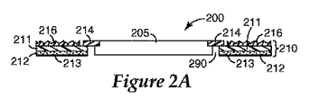
図2A及び2Bは、それぞれ、一実施形態による、GIG 200の断面図及び平面図を提供する。GIG 200は、ガスケット210及びガス拡散層(GDL)205を含む。GDL 205は、反応ガスを通過させる一方、電極から電流を回収することができる、いずれかの材料から作成することができ、典型的に、織られた若しくは不織の炭素繊維紙又は布である。
2A and 2B provide cross-sectional and top views, respectively, of
ガスケット210は、GDL 205に対して配置された第1のガスケット層211を含む、層構造体である。一実施形態においては、図2Aに最もよく見られるように、GDL 205は、第1のガスケット層211内の開口290よりわずかに小さい。本実施形態においては、GDL 205は、第1のガスケット層211の開口290内に配置される。第1のガスケット層211は、ポリイミド、ポリエチレンナフタレート(PEN)、ポリエチレンテレフタレート(PET)、及び/又は十分に薄く、十分に強く、燃料電池環境、すなわち、水、水素、及び/又は酸素の存在下での80〜100℃の温度と十分に適合性のある、硬質高分子材料を含む、その他の類似材料等、様々な種類のポリマー材料を含んでもよい。
The
ガスケット210は、第1のガスケット層211の1つの表面上に置かれた、接着剤層212を含み、所望により、接着剤ライナー213を含む。第1のガスケット層211及び接着剤層212の材料は、接着剤層212が第1のガスケット層211にしっかりと接着するように選択される。接着剤層212は、感圧性接着剤(PSA)又は熱活性接着剤を含んでもよい。例えば、接着剤層212は、次の、アクリル系PSA、ゴム系接着剤、エチレン無水マレイン酸コポリマー類、エチレン又はプロピレンを有する1−オクテンのコポリマー類等のオレフィン接着剤、ニトリル系接着剤、エポキシ系接着剤、及びウレタン系接着剤のいずれかを含んでもよい。幾つかの実施形態においては、接着剤層212は、サーモボンド(Thermobond)845(ポリエチレンマレアート系)又はサーモボンド583(ニトリルゴム系)等の熱的に活性化される接着剤を含んでもよい。
The
ガスケット210は、GDL 205及び第1のガスケット層211を共に固着する、第2のガスケット層214を含む。本明細書に記載される様々な実施形態において、第2のガスケット層214は、室温で固体であり、GDL 205と第1のガスケット層211との間に固着を形成するために、熱及び/又は圧力で加工することができる、材料から形成されてもよい。材料への熱及び/又は圧力の適用は、GDL 205と第1のガスケット層211との間に固着を形成するのに十分に材料が流れる、又は変形するようにしてもよい。第2のガスケット層214を形成するために使用される材料は、本明細書において、熱/圧力加工可能な材料と称される。第2のガスケット層の形成に適した材料には、例えば、熱加工可能なポリマー類又は熱可塑性封止材料が挙げられる。熱可塑性材料は、フッ素樹脂のようなTHV(テトラフルオロエチレン、ヘキサフルオロプロピレン、及び二フッ化ビニリデンのターポリマー)、ポリエチレン、エチレン及びアクリル酸のもの等のポリエチレンのコポリマー類、サーモボンド(Thermobond)845(3Mによって製造される、例えば、ポリエチレン無水マレイン酸コポリマー)、及びサーモボンド(Thermobond)668(3Mによって製造される、例えば、ポリエステル)であってよい。これらの材料の混合物又は炭素、ガラス、セラミック等の充填剤を有するこれらの複合材料もまた、熱可塑性樹脂として使用されてもよい。溶融範囲は、約50〜180℃であってよく、例えば、又は約100〜150℃であってよい。
The
一実施形態においては、第1のガスケット層211及び/又は第2のガスケット層214の表面は、ミクロ構造形状216等の表面形状を含んでもよい。幾つかの燃料電池構成においては、ミクロ構造形状216は、GIGの封止特性を改善する。ミクロ構造形状216は、密接に詰められた六角形、又はいずれかのその他の形状を含む、様々な形状で形成されてもよい。特定の実施形態においては、ミクロ構造形状216の高さは、GIGの封止表面が、流れ場の上面と同一平面上である、又は封止表面がある程度陥凹している、単極流れ場プレートに収まるように選択することができる。陥凹したバージョンは、ミクロ構造形状216をより高くできるようにし、プレート厚さの不均等性が存在する場合の、封止許容度の改善を可能にする。場合によっては、第1及び/又は第2のガスケット層211、214の好ましい表面形状216は、封止を作り出すための適切な隆起部を有する、燃料電池スタック流れ場プレートへの固着を容易にするために、実質的に平らである。
In one embodiment, the surface of the
一構成においては、第2のガスケット層214を形成するために、熱/圧力加工可能な材料が使用される。GDL 205は、第1のガスケット層211の開口290内に置かれる。第2のガスケット層214を形成するために使用される熱/圧力加工可能な材料は、開口を有する構造に切断され、GDL 205の外縁206(図2B)の上方及び第1のガスケット層211の内縁217の上方に定置される。定置後、サブアセンブリに熱及び/又は圧力が適用され、熱/圧力加工可能な材料の一部が、GDL 205の隣接した縁及び/又は表面、並びに第1のガスケット層211の隣接した縁及び/又は表面に流れるようにする。熱及び/又は圧力の適用は、第2のガスケット層214が、第1のガスケット層211及びGDL 205の両方に接着するようにし、したがって第1のガスケット層211をGDL 205に接着する。加熱プレスに使用される圧縮ツールの表面は、第1及び/又は第2のガスケット層211、214の表面上にミクロ構造形状を形成するために、その上にミクロ構造形状(負の)を有してもよい。幾つかの実施形態においては、GIG 201のGDL 205は、図2Cに図示されるように、1つの表面上に置かれた触媒層215を追加で含んでもよい。
In one configuration, a heat / pressure processable material is used to form the
図2D及び2Eは、接着剤層222、及び任意の接着剤ライナー223を有する第1のガスケット層221が、GDL 225の下に配置される、実施形態を図示する。図2D及び2Eに図示される実施形態においては、第2のガスケット層224は、GDL 225に隣接した第1のガスケット層221上に置かれる。幾つかの実施においては、第2のガスケット層224を形成する材料は、GDL 225の上面に重なってもよい。第2のガスケット224層は、ミクロ構造形状226(図2D)を含んでもよく、又は実質的に平らな封止面228(図2E)を有してもよい。
2D and 2E illustrate an embodiment in which a
幾つかの実施形態においては、GIGは、第1のガスケット層上へのGDLの配設の前に、第2のガスケット層を形成するために使用される熱/圧力加工可能なガスケット材料を、第1のガスケット層上に定置する、又は堆積することによって、組み立てられる。例えば、熱/圧力加工可能なガスケット材料は、第1のガスケット層の表面上にスクリーン印刷されてもよく、又はその他の方法で堆積されてもよい。次いでGDLは、第1のガスケット層の上方に配置される。幾つかの実施においては、第2のガスケット層のガスケット材料の一部分は、GDLと第1のガスケット層との間に置かれてもよい。GDLの定置後、サブアセンブリに熱及び/又は圧力が適用され、熱/圧力加工可能な材料の一部がGDLの隣接した縁及び/又は表面、並びに/若しくは第1のガスケット層の隣接した縁及び/又は表面に流れるようにする。 In some embodiments, the GIG includes a heat / pressure processable gasket material used to form the second gasket layer prior to the placement of the GDL on the first gasket layer. Assembled by placing or depositing on the first gasket layer. For example, a heat / pressure processable gasket material may be screen printed onto the surface of the first gasket layer or otherwise deposited. The GDL is then placed over the first gasket layer. In some implementations, a portion of the gasket material of the second gasket layer may be placed between the GDL and the first gasket layer. After placement of the GDL, heat and / or pressure is applied to the subassembly so that a portion of the heat / pressure processable material may be adjacent edges and / or surfaces of the GDL and / or adjacent edges of the first gasket layer. And / or flow to the surface.
図2Fは、上述されるプロセスに従って形成されてもよい、GIG 204を図示する。本実施においては、第2のガスケット層の熱/圧力加工可能な材料285の一部は、GDL 280と第1のガスケット層281との間に堆積される。第1のガスケット層281は、接着剤層282、及び任意の接着剤ライナー283を含む。第2のガスケット層284は、ミクロ構造形状を含んでもよく、又は図2Fに図示されるように実質的に平らであってもよい。
FIG. 2F illustrates
GIG 200、201、202、及び/又は203の製作のための方法及び装置が以下に記載される。GIG及びMEA、並びに/又はGIGを組み込んだ燃料電池に関する更なる詳細は、本願と同時に出願され、参照によって本明細書に組み込まれる、代理人整理番号第62462US002号によって特定される同一所有者の米国特許出願に記載される。
Methods and apparatus for fabrication of
図2Aから2Cに図示されるもの等、複数個のGIGを含むウェブは、ロール・ツー・ロールプロセス下のGIGサブアセンブリウェブとして製作されてもよい。図3Aは、一実施形態による、複数個のGIG 310を含むGIGサブアセンブリウェブ300の断面図を図示する。GIGサブアセンブリコンポーネントのハンドリング及び移送を容易にするために、製作プロセス中、第2のガスケット層314を形成する熱/圧力加工可能な材料は、第1のキャリアウェブ331上に堆積されてもよく、第1のガスケット層は、第2のキャリアウェブ332上に置かれてもよい。
A web comprising a plurality of GIGs, such as that illustrated in FIGS. 2A-2C, may be fabricated as a GIG subassembly web under a roll-to-roll process. FIG. 3A illustrates a cross-sectional view of a
製作中、第2のガスケット層314を形成する熱/圧力加工可能な材料は、一対の固着ローラー等の圧縮装置で、第1及び第2のキャリアウェブ331、332の移動によって、第1のガスケット材料311及びGDL 305に接合される。固着ローラーで、熱/圧力加工可能な材料に熱及び/又は圧力が適用され、材料が流れる、又は変形するようにし、第1のガスケット材料311をGDL 305に固着する、第2のガスケット層314を形成する。それぞれのGIG 310は、平らなガスケット表面を有してもよく、又はミクロ構造形状316を含むガスケット表面を有してもよい。接着剤層312及び任意の接着剤ライナー313は、第1のガスケット層311上に置かれる。図3Bは、第2のキャリアウェブ332を含み、第1のキャリアウェブがない状態のGIGサブアセンブリウェブの平面図(原寸に比例していない)を図示する。
During fabrication, the heat / pressure processable material forming the
図2Dから2Eに図示されるもの等の複数個のGIGを含むウェブが、図3Cに図示される。図3Cは、一実施形態による、複数個のGIG 320を含むGIGウェブ302の断面図を図示する。GIGサブアセンブリコンポーネントのハンドリング及び移送を容易にするために、製作プロセス中、第2のガスケット層324を形成する熱/圧力加工可能な材料は、第1のキャリアウェブ331上に堆積されてもよく、第1のガスケット層は、第2のキャリアウェブ332上に置かれてもよい。
A web including a plurality of GIGs, such as those illustrated in FIGS. 2D-2E, is illustrated in FIG. 3C. FIG. 3C illustrates a cross-sectional view of a
製作中、第2のガスケット層324を形成する熱/圧力加工可能な材料は、一対の固着ローラー等の圧縮装置で、第1及び第2のキャリアウェブ331、332の移動によって、第1のガスケット層321及びGDL 325に接合される。固着ローラーで、熱/圧力加工可能な材料に熱及び/又は圧力が適用され、材料が流れる、又は変形するようにし、第1のガスケット材料321をGDL 325に固着する、第2のガスケット層324を形成する。接着剤層322及び任意の接着剤ライナー323は、第1のガスケット層321上に置かれる。
During fabrication, the heat / pressure processable material forming the
特定の実施形態においては、上述され、図2Aから3Cに描写されるプロセスに従って製作されるGIG及び/又はGIGサブアセンブリウェブは、個々のMEA又はMEAサブアセンブリウェブを形成するために、後続のプロセスで使用されてもよい。図4A及び4Bは、電解質膜の第1及び第2の表面上に置かれたGIGを使用して製作されたMEAを図示する。図4Aは、触媒コーティングされた電解質膜(CCM)430の第1及び第2の表面上に置かれた、GIG 410、420を図示する。それぞれのGIG 410、420は、ミクロ構造形状416、426を含んでも含まなくてもよい、第1のガスケット層411、421を含む。接着剤層412、422は、第1のガスケット層411、421のそれぞれの上に置かれる。GIG 410、420の第1のガスケット層411、421のそれぞれは、GDL 405、406が開口内に配設された、開口を有する。
In certain embodiments, a GIG and / or GIG subassembly web fabricated according to the process described above and depicted in FIGS. 2A-3C is a subsequent process to form an individual MEA or MEA subassembly web. May be used. 4A and 4B illustrate a MEA fabricated using GIG placed on the first and second surfaces of the electrolyte membrane. FIG. 4A illustrates
図4Aに図示されるGDL 405、406は、GDL 405、406が第1のガスケット層411、421の開口内に収まるように、第1のガスケット層の開口411、421よりわずかに小さい。幾つかの実施形態においては、GDL 405、406は、GDL 405、406の外縁417、427が、第1のガスケット層411、421の内縁418、428に重なるように、第1のガスケット層の開口411、421よりわずかに大きくてもよい。それぞれのGIGは、熱/圧力加工可能な材料から形成された第2のガスケット層414、424を含む。
The
熱及び圧力の適用後、熱/圧力加工可能な材料は、第1のガスケット層411、421及びGDL 405、406を固着する第2のガスケット層414、424を形成するように流れる、又は変形する。固着プロセス中、GIG 401の封止特性を向上するために、第2のガスケット層414及び/又は第1のガスケット層411に、ミクロ構造形状が付与されてもよい。
After application of heat and pressure, the heat / pressure processable material flows or deforms to form a
図4Bは、GIG 450、460が、電解質膜436に隣接したGDL 407、408の表面上に触媒層433、434を含むことを除き、図4Aに図示されるものと類似する、MEA 401を図示する。本実施形態においては、電解質膜436は、触媒層を含んでも含まなくてもよい。
FIG. 4B illustrates an
図4Cは、膜435及び触媒層431、432を有する、触媒コーティングされた電解質膜(CCM)430の第1及び第2の表面上に置かれた、GIG 480、490を図示する。それぞれのGIG 480、490は、第1のガスケット層441、451を含む。接着剤層442、452は、第1のガスケット層441、451のそれぞれの上に置かれる。本実施形態においては、GDL 403、404は、第1のガスケット層441、451に重なる。それぞれのGIG 480、490は、熱/圧力加工可能な材料から形成された第2のガスケット層444、454を含む。その他の実施形態においては、第2のガスケット層の表面は、実質的に平らであってもよいが、本実施形態においては、第2のガスケット層444、454は、ミクロ構造形状446、456を含む。
FIG. 4C illustrates
図5は、一実施形態による、ロール・ツー・ロール製造プロセスによって製作されてもよい複数個のMEA 510を含む、MEAサブアセンブリウェブ500の断面図を図示する。第2のキャリアウェブ、及び使用される場合、接着剤ライナーのそれぞれのGIGサブアセンブリからの取り外しの後、MEAサブアセンブリウェブ500が、2つのGIGサブアセンブリ、図3Aに図示されるようなウェブを使用して製作されてもよい。GIGサブアセンブリ501のうちの1つは、第1のガスケット層511の接着剤層512を介して、CCM 530の1つの表面に接着剤で固着される。もう一方のGIGサブアセンブリ502は、MEAサブアセンブリウェブ500を形成するために、CCM 530の反対側の表面に接着剤で固着される。プロセスは、GIGサブアセンブリウェブ501、502のそれぞれの第1のキャリアウェブ531をそのままにし、これは、後続の加工工程におけるMEAサブアセンブリウェブ500のハンドリングを容易にし得る。
FIG. 5 illustrates a cross-sectional view of an
ここで図6を参照すると、本発明の実施形態による、燃料電池スタック600の単一電池アセンブリの断面図が図示されている。燃料電池スタックは、上述されるように、液体フロープレート660と661との間に挟持された、2つのGIG 651、655を組み込んだ5層MEA 650を含む。
Referring now to FIG. 6, a cross-sectional view of a single cell assembly of a
MEA及び流れ場プレートを含む燃料電池の製作は、ロール・ツー・ロールプロセスによって達成されてもよい。ロール・ツー・ロール加工に適した流れ場セパレータプレートを含む、ロール・ツー・ロール燃料電池製作に有用な方法及びデバイスは、その全体が参照として本明細書に組み込まれる、同一所有者の米国特許公開第20060141328号に記載される。 Fabrication of a fuel cell that includes an MEA and a flow field plate may be accomplished by a roll-to-roll process. Methods and devices useful for roll-to-roll fuel cell fabrication, including flow field separator plates suitable for roll-to-roll processing, are commonly owned U.S. patents, incorporated herein by reference in their entirety. It is described in the publication 2006014141328.
燃料電池600のMEA 650は、陽極触媒層653と陰極触媒層654との間に電解質膜652を含む。幾つかの構成においては、陽極触媒層653及び陰極触媒層654の一方又は両方は、触媒コーティングされた膜(CCM)を形成する電解質膜652の表面上に置かれてもよい。その他の構成においては、既に図4Bに図示されたように、触媒層653、654は、GDL 605、625の表面上に置かれてもよい。更にその他の構成においては、触媒層653、654は、部分的に電解質膜652上及び部分的にGDL 605、625上に置かれてもよい。
The
陽極及び陰極触媒層653、654は、本明細書に記載されるように構成される、電解質膜652及びGIG 651、655との間に置かれる。それぞれのGIG 651、655は、GDL 605、625、第1のガスケット層611、621、接着剤層612、622、及び第1のガスケット層611、621をGDL 605、625に固着する、第2のガスケット層614、624を含む。ガスケット密封MEA 650の組み立ての前に、GIG 651、655は、所望により、MEA 650の組み立て中に取り外される、接着剤ライナーを含む。接着剤ライナーの取り外し後、GIG 651、655の接着剤層612、622は、ガスケット密封MEA 650を形成するために、CCMの表面及び/又は幾つかの構成において互いに接着する。
The anode and cathode catalyst layers 653, 654 are placed between the
図6に提供される実施例においては、GIG 651、655の第1のガスケット層611、621及び/又は第2のガスケット層614、624は、GIG 651、655と燃料流プレート660、661との間の封止を容易にするために、任意のミクロ構造形状616、626を含む。流れ場プレート660、661のそれぞれは、水素及び酸素燃料が通過する、ガス流路643及びポートの領域を含む。図6に描写される構成においては、流れ場プレート660、661は、単極流れ場プレートとして構成される。その他の構成においては、流れ場プレート660、661は、燃料電池スタックに対する所望の電圧を達成するように複数のMEAの積み重ねを容易にするために、双極液体フロープレートを含んでもよい。
In the embodiment provided in FIG. 6, the first gasket layers 611, 621 and / or the second gasket layers 614, 624 of the
本発明の実施において、いずれかの適した電解質膜が使用されてもよい。有用なPEM厚さの範囲は、約200μm〜約15μmである。テトラフルオロエチレン(TFE)のコポリマー類及び化学式:FSO2−CF2−CF2−O−CF(CF3)−CF2−O−CF=CF2と一致するコモノマーは、既知であり、スルホン酸形状、すなわち、HSO3−に加水分解されたFSO2−末端基を有する状態で、デラウェア州ウィルミントン(Wilmington, Delaware)にあるデュポン・ケミカル社(DuPont Chemical Company)から、商標名ナフィオン(NAFION)(登録商標)で販売されている。ナフィオン(NAFION)(登録商標)は、燃料電池で使用するためのポリマー電解質膜の作製に一般的に使用される。また、テトラフルオロエチレン(TFE)のコポリマー類及び化学式:FSO2−CF2−CF2−O−CF=CF2と一致するコモノマーも既知であり、スルホン酸形状、すなわち、HSO3−に加水分解されたFSO2−末端基を有する状態で、燃料電池で使用するためのポリマー電解質膜の作製に使用される。最も好ましいものは、テトラフルオロエチレン(TFE)のコポリマー類及びHSO3−に加水分解されたFSO2−末端基を有する、FSO2−CF2CF2CF2CF2−O−CF=CF2である。PEM構造体に適したその他の材料は、参照として本明細書に組み込まれる、2005年9月13日に出願された同一所有者の米国特許出願第11/225690号に記載される。 Any suitable electrolyte membrane may be used in the practice of the present invention. A useful PEM thickness range is from about 200 μm to about 15 μm. Copolymers of tetrafluoroethylene (TFE) and comonomers corresponding to the chemical formula: FSO2-CF2-CF2-O-CF (CF3) -CF2-O-CF = CF2 are known and are in the sulfonic acid form, ie HSO3- Sold under the trade name NAFION® from DuPont Chemical Company in Wilmington, Delaware, with a hydrolyzed FSO2-end group. Yes. NAFION® is commonly used to make polymer electrolyte membranes for use in fuel cells. Also known are copolymers of tetrafluoroethylene (TFE) and comonomers consistent with the chemical formula: FSO2-CF2-CF2-O-CF = CF2, sulfonic acid form, ie, FSO2-terminated hydrolyzed to HSO3-. In the state which has group, it is used for preparation of the polymer electrolyte membrane for using with a fuel cell. Most preferred is FSO2-CF2CF2CF2CF2-O-CF = CF2, which has copolymers of tetrafluoroethylene (TFE) and FSO2-terminal groups hydrolyzed to HSO3-. Other materials suitable for PEM structures are described in commonly owned US patent application Ser. No. 11/25690 filed on Sep. 13, 2005, which is incorporated herein by reference.
幾つかの実施形態においては、触媒層は、塩化白金酸の還元等の湿式化学的方法によって、より大きな炭素粒子の上にコーティングされたPt又はPt合金を含んでもよい。本形状の触媒は、イオノマー系結合剤、溶媒、及び、多くの場合にはポリテトラフルオロエチレン(PTFE)粒子によって分散され、膜又はGDLのいずれかに塗布されるインク、ペースト、又は分散体を形成する。 In some embodiments, the catalyst layer may comprise Pt or a Pt alloy coated on larger carbon particles by a wet chemical method such as reduction of chloroplatinic acid. This form of catalyst comprises an ink, paste, or dispersion dispersed in an ionomer binder, solvent, and often polytetrafluoroethylene (PTFE) particles, applied to either a film or GDL. Form.
幾つかの実施形態においては、触媒層は、粒子を担持するナノ構造化担持成分、又は触媒材料のナノ構造化薄膜(NSTF)を含んでもよい。ナノ構造化触媒層は、担持体としての炭素粒子を含まず、したがって、触媒粒子の高密度分散を形成する、電解質膜の非常に薄い表面層に組み込まれてもよい。NSTF触媒層の使用は、分散方法によって形成された触媒層より大幅に高い触媒利用を可能にし、炭素担持体がないことによる、高電位及び高温での腐食に対するより高い耐性を提供する。幾つかの実施においては、CCMの触媒表面積は、電解質膜上にミクロ構造形状をエンボス加工することによって、更に向上されてもよい。NSTF触媒は、熱及び圧力下での触媒の電解質膜への積層転写の際に、電解質膜の表面をミクロ複製にする、ミクロ構造化触媒転写基材上にコーティングされる。ミクロ構造化触媒転写基材を目的とする方法及びシステムは、参照によって本明細書に組み込まれる、同一所有者の米国特許第6,136,412号に記載される。ミクロ構造化電解質膜及びNSTF触媒層を作製するための様々な方法は、参照によって本明細書に組み込まれる、次の同一所有者の特許文献、米国特許第4,812,352号及び同第5,879,827号、並びに2005年9月13日に出願された米国特許出願第S/N11/225,690号及び2005年9月13日に出願された米国特許出願第S/N11/224,879号に記載される。 In some embodiments, the catalyst layer may include a nanostructured support component that supports particles, or a nanostructured thin film (NSTF) of catalyst material. The nanostructured catalyst layer does not include carbon particles as a support and may therefore be incorporated into a very thin surface layer of the electrolyte membrane that forms a dense dispersion of catalyst particles. The use of NSTF catalyst layer allows for significantly higher catalyst utilization than the catalyst layer formed by the dispersion method and provides greater resistance to corrosion at high potentials and temperatures due to the absence of a carbon support. In some implementations, the catalyst surface area of the CCM may be further improved by embossing the microstructure shape on the electrolyte membrane. NSTF catalyst is coated on a microstructured catalyst transfer substrate that makes the surface of the electrolyte membrane micro-replicated during layer transfer of the catalyst to the electrolyte membrane under heat and pressure. Methods and systems aimed at microstructured catalyst transfer substrates are described in commonly owned US Pat. No. 6,136,412, which is incorporated herein by reference. Various methods for making microstructured electrolyte membranes and NSTF catalyst layers are described in the following commonly owned patent documents, US Pat. Nos. 4,812,352 and 5, which are incorporated herein by reference. , 879,827, and U.S. Patent Application No. S / N11 / 225,690 filed on September 13, 2005, and U.S. Patent Application No. S / N11 / 224 filed on September 13, 2005, 879.
NSTF触媒層は、触媒材料の針状ナノ構造化担持体上への真空蒸着によって形成されてもよい、細長いナノスケールの粒子を含む。本発明での使用に適したナノ構造化担持体は、C.I.顔料レッド(C.I. PIGMENT RED)149(ペリレンレッド)等の有機顔料のウィスカーを含んでもよい。結晶性ウィスカーは、実質的に均一であるが、同一ではない断面、及び高い長さ対幅比率を有する。ナノ構造化担持体ウィスカーは、触媒作用に適しており、ウィスカーに、複数の触媒部位として働くことができる、微細なナノスケールの表面構造を付与する、コーティング材料でコーティングされる。 The NSTF catalyst layer includes elongated nanoscale particles that may be formed by vacuum deposition of the catalyst material onto a needle-like nanostructured support. Nanostructured supports suitable for use in the present invention include C.I. I. Organic pigment whiskers such as C.I. PIGMENT RED 149 (perylene red) may also be included. Crystalline whiskers have a substantially uniform but non-identical cross section and a high length to width ratio. Nanostructured support whiskers are suitable for catalysis and are coated with a coating material that imparts a fine nanoscale surface structure to the whiskers that can serve as multiple catalytic sites.
特定の実施においては、ナノ構造化担持成分は、連続らせん転位成長によって、伸張されてもよい。ナノ構造化担持成分を長くすること及び/又はその密度を高くすることは、触媒作用の増加した表面積を可能にする。ナノ構造化担持成分を長くするためのプロセスは、既に組み込まれている米国特許出願第11/225,690号に記載される。更に、又はあるいは、ナノ構造化担持成分の多層もまた、増加した表面積を提供する。ナノ構造化担持成分の多層を製造するためのプロセスは、既に組み込まれている米国特許出願第11/224,879号に記載される。ナノ構造化担持成分は、ナノ構造化薄膜触媒層を形成するために、触媒材料でコーティングされる。1つの実施によると、触媒材料は、白金族金属等の金属を含む。一実施形態においては、触媒コーティングされたナノ構造化担持成分は、触媒コーティングされた膜を形成するために、電解質膜の表面に転写されてもよい。その他の実施形態においては、触媒コーティングされたナノ構造化担持成分は、GDL表面上に形成されてもよい。 In certain implementations, the nanostructured support component may be stretched by continuous screw dislocation growth. Increasing the nanostructured support component and / or increasing its density allows for increased catalytic surface area. A process for lengthening the nanostructured support component is described in previously incorporated US patent application Ser. No. 11 / 225,690. Additionally or alternatively, multiple layers of nanostructured support components also provide increased surface area. A process for producing multiple layers of nanostructured support components is described in previously incorporated US patent application Ser. No. 11 / 224,879. The nanostructured support component is coated with a catalyst material to form a nanostructured thin film catalyst layer. According to one implementation, the catalyst material comprises a metal, such as a platinum group metal. In one embodiment, the catalyst coated nanostructured support component may be transferred to the surface of the electrolyte membrane to form a catalyst coated membrane. In other embodiments, the catalyst coated nanostructured support component may be formed on the GDL surface.
GDLは、反応ガスを通過させる一方、電極から電流を回収することができる、いずれかの材料であってよく、典型的に、織られた、又は不織の炭素繊維紙又は布である。GDLは、ガス状反応物質及び水蒸気の触媒及び膜への多孔質アクセスを提供し、また、外部負荷に電力を供給するために、触媒層で生成される電流を回収する。 The GDL may be any material that allows the reaction gas to pass while recovering current from the electrodes, and is typically a woven or non-woven carbon fiber paper or cloth. GDL provides porous access to gaseous reactants and water vapor catalyst and membrane, and also recovers the current generated in the catalyst layer to power external loads.
GDLは、炭素繊維構造体(例えば、織布及び不織布炭素繊維構造体)等のいずれかの適した導電性多孔質基材であってよい。市販の炭素繊維構造体類の例には、マサチューセッツ州ローウェル(Lowell, MA)にあるバラード・マテリアル・プロダクツ(Ballard Material Products)の取引表記「アヴカーブ(AvCarb)P50」炭素繊維紙、マサチューセッツ州ウォバーン(Woburn, MA)にあるエレクトロケム社(ElectroChem, Inc.)から入手可能な「東レ(Toray)」カーボン紙、マサチューセッツ州ローレンス(Lawrence, MA)にあるスペクトラコープ(Spectracorp)の「スペクトラカーブ(SpectraCarb)」、マサチューセッツ州イースト・ワルポール(East Walpole, MA)にあるハリングスワース・アンド・ヴォーズ・カンパニー(Hollingsworth & Vose Company)の「AFN」不織炭素布、及びミズーリ州セント・ルイス(St. Louis MO)のゾルテック・カンパニーズ社(Zoltek Companies, Inc.)の「ゾルテック(Zoltek)」炭素布、並びに日本、東京にある三菱レイヨン社(Mitsubishi Rayon Co.)の「U−105」炭素布が挙げられる。また、GDLは、疎水性を向上するため又は付与するために、処理されてもよい。例えば、GDLは、ポリテトラフルオロエチレン(PTFE)及びフッ素化エチレンプロピレン(FEP)等の高度フッ素化ポリマー類で処理されてもよい。 The GDL may be any suitable conductive porous substrate such as a carbon fiber structure (eg, woven and non-woven carbon fiber structures). Examples of commercially available carbon fiber structures include Ballard Material Products' trade designation “AvCarb P50” carbon fiber paper in Wowell, Mass., Woburn, Massachusetts ( "Toray" carbon paper available from ElectroChem, Inc. in Woburn, MA, "SpectraCarb" from Spectracorp in Lawrence, Massachusetts "AFN" non-woven carbon fabric from Hollingsworth & Vose Company in East Walpole, MA, and St. Louis MO, St. Louis ) Zoltek Companies, Inc.'s "Zoltek" Carbon cloth, as well as Japan, and a "U-105" carbon cloth of Mitsubishi Rayon Co., Ltd. in Tokyo (Mitsubishi Rayon Co.). The GDL may also be treated to improve or impart hydrophobicity. For example, GDL may be treated with highly fluorinated polymers such as polytetrafluoroethylene (PTFE) and fluorinated ethylene propylene (FEP).
本発明の実施形態は、図3A、3B、及び5に図示されるようなロール製品型GIG並びに/又はMEAサブアセンブリウェブを製作するためのプロセスを目的とする。図7Aは、本発明の実施形態による、複数のGIGを含むGIGサブアセンブリウェブを製作するために使用されてもよい方法を図示する、フローチャートである。該方法は、製作プロセスによる様々な材料ウェブの移動を伴う。プロセスは、離間した開口を有する熱/圧力加工可能な材料のウェブを固着ステーションに移送する工程710を含む。典型的に、離間した開口を有する熱/圧力加工可能な材料は、キャリアウェブ又はコンベヤーを介した製作プロセス中に担持体を必要とする、比較的壊れやすい梯子構造体である。例えば、一実施形態においては、熱/圧力加工可能な材料は、粘着性が中程度の接着剤を使用して、接着剤でキャリアウェブに付着されてもよい。熱/圧力加工可能な材料を上方に堆積されたキャリアウェブは、巻き出しホイール又はその他の源から供給されてもよい。別の実施形態においては、熱/圧力加工可能な材料は、製作プロセスの一部によって、真空コンベヤー上に担持され、移送されてもよい。
Embodiments of the present invention are directed to a process for making a roll product type GIG and / or MEA subassembly web as illustrated in FIGS. 3A, 3B, and 5. FIG. 7A is a flowchart illustrating a method that may be used to fabricate a GIG subassembly web that includes multiple GIGs, according to an embodiment of the invention. The method involves the movement of various material webs through the fabrication process. The process includes a
また、プロセスは、離間した開口及びGDLを有する第1のガスケット材料を固着ステーションに移送する工程720を含む。一構成においては、GDLは、第1のガスケット層の開口内に置かれる。第1のガスケット層及びGDLは、上述されるような第2のキャリアウェブ又はコンベヤーを介して移送されてもよい。第1のガスケット層は、任意の接着剤ライナーを有する粘着性の強い接着剤を含んでもよい、接着剤層を含む。第1のガスケット層の接着剤層は、GIGサブアセンブリを電解質膜又はCCMに付着させるために、MEAサブアセンブリウェブの製作で使用される。
The process also includes a
一実施においては、第1のガスケット層は、接着剤層/接着剤ライナーを下向きにして、第2のキャリアウェブ上に配向される。第1のガスケット層は、例えば粘着性の低い接着剤を介して、第2のキャリアウェブに接着してもよい。GDLは、第1のガスケット層の開口内のキャリアウェブ上に置かれ、また、粘着性の低い接着剤を介して、キャリアウェブに接着剤で付着されてもよい。 In one implementation, the first gasket layer is oriented on the second carrier web with the adhesive layer / adhesive liner facing down. The first gasket layer may be bonded to the second carrier web via, for example, a low-tack adhesive. The GDL may be placed on the carrier web in the opening of the first gasket layer and may be adhesively attached to the carrier web via a low tack adhesive.
熱/圧力加工可能な材料並びに第1のガスケット層及びGDLは、整合730される。例えば、熱/圧力加工可能な材料並びに第1のガスケット層及びGDLとの間の位置合わせは、熱/圧力加工可能な材料をGDLの外辺部に定置するように、制御されてもよい。一実施形態においては、梯子のようなウェブとして作られる熱/圧力加工可能な材料は、第1のガスケット層の開口で、熱/圧力加工可能な材料がGDLの外縁及び第1のガスケット層の内縁を被覆するように、第1のガスケット層及びGDLに整合される。例えば、熱/圧力加工可能な材料は、約1〜2mm、又はその他の量だけ、GDLの外縁及び/又は第1のガスケット層の内縁に重なってもよい。 The heat / pressure processable material and the first gasket layer and GDL are aligned 730. For example, the alignment between the heat / pressure processable material and the first gasket layer and the GDL may be controlled to place the heat / pressure processable material on the outer edge of the GDL. In one embodiment, the heat / pressure processable material made as a ladder-like web is at the opening of the first gasket layer and the heat / pressure processable material is the outer edge of the GDL and the first gasket layer. Matched to the first gasket layer and the GDL to cover the inner edge. For example, the heat / pressure processable material may overlap the outer edge of the GDL and / or the inner edge of the first gasket layer by about 1-2 mm, or other amounts.
整合後、熱/圧力加工可能な材料を第1のガスケット層及びGDLに固着740するために、熱及び圧力が使用される。一構成においては、一対の加熱固着ローラーを介して、熱/圧力加工可能な材料、第1のガスケット層、及びGDLに熱及び圧力が適用される。固着ローラーによって適用される熱及び圧力は、熱/圧力加工可能な材料を、GDLの縁及び/又は表面、並びに第1のガスケット層の縁及び/又は表面に押し進める。固着後、熱/圧力加工可能な材料は、第1のガスケット層をGDLに付着させる、第2のガスケット層を形成する。固着ローラーの表面は、第1及び/又は第2のガスケット層の表面上にミクロ構造形状を形成するために、その上にミクロ構造形状(負の)を有してもよい。熱不活性化感圧性接着剤を介して第1のガスケット層及びGDLに付着されてもよい第2のキャリアウェブは、剥離ステーションで剥離され、取り外されてもよい。固着後、結果として生じるロール製品型GIGサブアセンブリウェブは、以下に記載されるように、ガスケット密封MEAサブアセンブリを形成するために、後で使用するために巻き上げられてもよく、又は即座に使用されてもよい。 After alignment, heat and pressure are used to secure 740 the heat / pressure processable material to the first gasket layer and GDL. In one configuration, heat and pressure are applied to the heat / pressure processable material, the first gasket layer, and the GDL via a pair of heat-fixing rollers. The heat and pressure applied by the anchoring roller drives the heat / pressure processable material to the edge and / or surface of the GDL and the edge and / or surface of the first gasket layer. After bonding, the heat / pressure processable material forms a second gasket layer that adheres the first gasket layer to the GDL. The surface of the anchoring roller may have a microstructure shape (negative) on it to form a microstructure shape on the surface of the first and / or second gasket layer. The second carrier web, which may be attached to the first gasket layer and GDL via a heat-inactivated pressure sensitive adhesive, may be peeled off at the peeling station and removed. After anchoring, the resulting roll product type GIG subassembly web may be rolled up for later use or used immediately to form a gasket sealed MEA subassembly as described below. May be.
図7Bは、本発明の実施形態による、複数のGIGを含むGIGサブアセンブリウェブを製作するために使用されてもよい方法を図示する、ダイアグラムである。図7Bに図示されるプロセスは、GDLの配設の前に、第1のガスケット層上に堆積された熱/加工可能なガスケット材料を使用する。熱/加工可能なガスケット材料は、離間した開口を切断する前に、第1のガスケット層の上に堆積されてもよい。あるいは、離間した開口を有する第1のガスケット層ウェブは、熱/圧力加工可能な材料が第1のガスケット層に堆積760される、シルクスクリーン印刷ステーション等の堆積ステーションに移送750される。GDLは、第1のガスケット層ウェブに対して配設770される。GDLは、それらが第1のガスケット層の開口内に収まるように配設されてもよく、又はGDLの縁が開口の縁に重なってもよい。幾つかの実施においては、GDLの縁は、熱/圧力加工可能な材料に重なる。熱/圧力加工可能な材料は、可変又は勾配厚さを有するように、第1のガスケット層上に堆積されてもよい。例えば、熱/圧力加工可能な材料は、その他の領域と比較して、GDLの下でより薄くなるように、堆積されてもよい。GDL上に堆積された熱/圧力加工可能な材料を有する第1のガスケット層ウェブは、固着ステーションで成形780される。成形プロセスは、第1のガスケット層をGDLに付着させる、第2のガスケット層を形成する。 FIG. 7B is a diagram illustrating a method that may be used to fabricate a GIG subassembly web that includes a plurality of GIGs, according to an embodiment of the invention. The process illustrated in FIG. 7B uses a heat / processable gasket material deposited on the first gasket layer prior to GDL deployment. A heat / processable gasket material may be deposited on the first gasket layer prior to cutting the spaced openings. Alternatively, the first gasket layer web having spaced openings is transferred 750 to a deposition station, such as a silk screen printing station, where heat / pressure processable material is deposited 760 on the first gasket layer. The GDL is disposed 770 against the first gasket layer web. The GDLs may be arranged so that they fit within the openings of the first gasket layer, or the edges of the GDL may overlap the edges of the openings. In some implementations, the edges of the GDL overlap the heat / pressure processable material. The heat / pressure processable material may be deposited on the first gasket layer to have a variable or gradient thickness. For example, the heat / pressure processable material may be deposited to be thinner under the GDL compared to other areas. A first gasket layer web having a heat / pressure processable material deposited on the GDL is molded 780 at a bonding station. The molding process forms a second gasket layer that attaches the first gasket layer to the GDL.
図8は、上述されるように、810で製作された第1及び第2のGIGサブアセンブリを使用して、連続プロセスでガスケット密封MEAサブアセンブリを製作するための方法を図示する、フローチャートである。第1及び第2のGIGサブアセンブリは、複数の固着ローラー及び/又はその他の固着装置を含んでもよい、固着ステーションに移送820される。触媒コーティングされた電解質膜又はCCMウェブは、固着ステーションに移送830される。 FIG. 8 is a flow chart illustrating a method for fabricating a gasket-sealed MEA subassembly in a continuous process using the first and second GIG subassemblies fabricated at 810 as described above. . The first and second GIG subassemblies are transferred 820 to an anchoring station, which may include a plurality of anchoring rollers and / or other anchoring devices. The catalyst coated electrolyte membrane or CCM web is transferred 830 to the anchoring station.
前述されるように、GIGサブアセンブリの形成は、固着ローラーを介して適用される熱及び圧力下で、GIGコンポーネントを固着する工程を含むことがある。固着後、GIGコンポーネントの移送を容易にするために使用される第2のキャリアウェブは、取り外される。幾つかの実施形態においては、第2のキャリアウェブは、熱不活性化感圧性接着剤によってGIGサブアセンブリに付着される。第2のキャリアウェブは、熱活性剥離プロセスによって、GIGサブアセンブリから取り外される。熱不活性化感圧性接着剤は、不混和性の材料から構成されてもよい。例えば、熱不活性化PSAは、スチレン−ブタジエンコポリマー類(SBS)に基づく熱溶解性コポリマーPSAを含んでもよい。PSAの接着性は、加熱によって永久的には除去され得ず、加熱固着ローラーからの流出の際、GDL及び第1のガスケットが第2のキャリアウェブから剥離するように、ウェブが加熱固着ローラーを通過する間だけ、除去され得る。 As described above, the formation of the GIG subassembly may include securing the GIG component under heat and pressure applied via a securing roller. After anchoring, the second carrier web used to facilitate transfer of the GIG component is removed. In some embodiments, the second carrier web is attached to the GIG subassembly by a heat deactivated pressure sensitive adhesive. The second carrier web is removed from the GIG subassembly by a heat activated release process. The heat-inactivated pressure sensitive adhesive may be composed of an immiscible material. For example, the heat-inactivated PSA may comprise a heat-soluble copolymer PSA based on styrene-butadiene copolymers (SBS). The adhesion of the PSA cannot be permanently removed by heating, and the web can be removed from the heated fixing roller so that the GDL and the first gasket peel from the second carrier web upon spilling from the heated fixing roller. It can be removed only during the passage.
第2のキャリアウェブは、それぞれのGIGサブアセンブリから剥離され、第1のガスケット層の接着剤層を暴露する。第1のガスケット層が接着剤ライナーを含む場合、剥離プロセスは、所望により、接着剤ライナーも第1のガスケット層から取り外してもよい。 The second carrier web is peeled from the respective GIG subassembly and exposes the adhesive layer of the first gasket layer. If the first gasket layer includes an adhesive liner, the release process may also remove the adhesive liner from the first gasket layer, if desired.
第1のGIGサブアセンブリウェブ及び第2のGIGアセンブリウェブは、固着ステーションで電解質膜ウェブに固着840される。一実施形態においては、GIGの第1のガスケット層の接着剤層は、粘着性の強い接着剤を含む。GIGサブアセンブリウェブは、室温で動作する固着ローラーを用いて、粘着性の強い接着剤を介して、触媒コーティングされた電解質膜又はCCMに固着される。室温での固着は、膜及び/又は触媒の分解を生じることのある、電解質膜及び触媒のより高い温度への暴露を回避する。幾つかの実施形態においては、固着ローラーは、熱及び圧力の両方を適用する。 The first GIG subassembly web and the second GIG assembly web are secured 840 to the electrolyte membrane web at a fastening station. In one embodiment, the adhesive layer of the first gasket layer of GIG includes a highly tacky adhesive. The GIG subassembly web is secured to the catalyst coated electrolyte membrane or CCM via a sticky adhesive using a sticking roller operating at room temperature. Room temperature sticking avoids exposure of the electrolyte membrane and catalyst to higher temperatures that can result in degradation of the membrane and / or catalyst. In some embodiments, the anchoring roller applies both heat and pressure.
幾つかの構成においては、電解質膜は、触媒層のない、連続した細長いウェブを含んでもよい。本構成においては、電解質膜は、GIGサブアセンブリのGDL上に置かれた触媒を有するGIGサブアセンブリへの高度な整合なしに、固着されてもよい。幾つかの構成においては、触媒層のある、又はない、複数個の別個の電解質膜は、連続ウェブ上で運ばれ、固着の前に、GIGサブアセンブリのGDLに整合されてもよい。その他の構成においては、連続電解質膜は、電解質膜の反対側の表面上に置かれた、連続した陽極及び陰極触媒層を含んでもよい。更に他の構成において、触媒は、連続電解質膜の表面上にパターン形成されてもよい。GIGサブアセンブリは、固着の前に、触媒パターンに整合されてもよい。 In some configurations, the electrolyte membrane may include a continuous elongated web without a catalyst layer. In this configuration, the electrolyte membrane may be secured without a high degree of alignment to the GIG subassembly having a catalyst placed on the GDL of the GIG subassembly. In some configurations, a plurality of separate electrolyte membranes with or without a catalyst layer may be carried on a continuous web and aligned with the GDL of the GIG subassembly prior to anchoring. In other configurations, the continuous electrolyte membrane may include a continuous anode and cathode catalyst layer placed on the opposite surface of the electrolyte membrane. In yet another configuration, the catalyst may be patterned on the surface of the continuous electrolyte membrane. The GIG subassembly may be aligned with the catalyst pattern prior to anchoring.
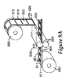
燃料電池材料の投入ウェブを加工し、ロール製品型燃料電池GIGサブアセンブリを製造する装置が、図9A及び9Bに図示される。大まかに言えば、図9A及び9Bの装置は、ロール製品型燃料電池コンポーネントを使用して、ロール製品型GIGサブアセンブリを製造することができる。図9A及び9Bの装置は、連続燃料電池製造プロセス下で、複数のGIGを含むサブアセンブリウェブを製作する、独自の手法を提供する。 An apparatus for processing an input web of fuel cell material to produce a roll product type fuel cell GIG subassembly is illustrated in FIGS. 9A and 9B. Broadly speaking, the apparatus of FIGS. 9A and 9B can use a roll product type fuel cell component to produce a roll product type GIG subassembly. The apparatus of FIGS. 9A and 9B provides a unique approach to making a subassembly web containing multiple GIGs under a continuous fuel cell manufacturing process.
ここで、図9Aを参照すると、梯子のような構造体として形成された熱/圧力加工可能な材料919は、第1のキャリアウェブ972に接着剤で付着される。第1のキャリアウェブ972及び熱/圧力加工可能な材料919は、第1の巻き出しホイール986から供給され、固着ローラー985に移送される。
Referring now to FIG. 9A, a heat / pressure
離間した開口961を有する第1のガスケット層911は、第2のキャリアウェブ971に接着剤で付着される。GDL 905は、第1のガスケット層911の離間した開口961内に配向される。第1のガスケット層911及びその中に置かれるGDL 905を有する第2のキャリアウェブ971は、第2の巻き出しホイール980から供給され、固着ローラー985に移送される。
A
熱/圧力加工可能な材料の梯子919、並びに第1のガスケット層911及びGDL 905を整合させるために、光学センサ998、999が使用されてもよい。光ファイバーセンサは、例えば、第1のガスケット層911の開口961及び/又はGDL 905の縁に対する、熱/圧力加工可能な材料の梯子919の開口920を検出することができる。特定の用途においては、整合は、燃料電池コンポーネント材料911、905、919、又はキャリアウェブ971、972上の基準マークの検出によって達成されてもよい。
当業者は、光学センサ又はその他の種類の感知配設を使用する整合を容易にするために、幾つかの技術及び構成を採用することができることを理解するであろう。一例として、第1のガスケット層911及び/又は第2のキャリアウェブ971上の基準マーク、並びに/若しくは第1のガスケット層911及び/又はその上に置かれたGDL 905の特徴を検出するために、1つ以上の光学センサ998を配置することができる。熱/圧力加工可能な梯子919及び/又は第1のキャリアウェブ972上の基準マーク、並びに/若しくはその上に堆積された熱/圧力加工可能な材料919の特徴を検出するために、1つ以上の第2の光学センサ999を配置することができる。センサ998、999からの情報は、それぞれのキャリアウェブ971、972の速度、長手方向位置、及び/又は横方向位置を制御するために、制御システムによって使用される。
One skilled in the art will appreciate that several techniques and configurations can be employed to facilitate alignment using optical sensors or other types of sensing arrangements. As an example, to detect fiducial marks on the
その上に置かれた熱/圧力加工可能な梯子919を有する第1のキャリアウェブ972、及びその上に置かれた第1のガスケット層911及びGDL 905を有する第2のキャリアウェブ971は、整合後、固着ローラー985で接合される。固着ローラー985によって適用される熱及び圧力は、熱/圧力加工可能な材料919が、第1のガスケット層911及びGDL 905の表面及び/又は縁の上並びに/又は中に流れるようにする。固着プロセスの後、熱/圧力加工可能な材料919から第2のガスケット層が形成される。第2のガスケット層は、第1のガスケット層911をGDL 905に付着させ、ロール製品型GIGサブアセンブリウェブ930を形成する。幾つかの実施においては、第2のキャリアウェブ971は、固着に続いて剥ぎ取られ、GIGサブアセンブリウェブ930は、保管のため及び/又は後続の加工における後の使用のために、巻き取りホイール上に巻き取られる。幾つかの実施においては、GIGサブアセンブリは、GIGサブアセンブリを組み込んだMEAサブアセンブリの形成のための加工ステージ等のその他の加工ステージに移送される。
A
図9Bは、その他の実施形態による、GIGを形成するための装置を図示する。本実施形態においては、第2のガスケット層を形成するために使用される熱/圧力加工可能な材料は、GDLを配置する前に、第1のガスケット層944上に堆積される。離間した開口945を有する第1のガスケット層944は、第1の巻き出しホイール943から供給され、第1のキャリアウェブ951上で堆積ステーション946に移送される。堆積ステーションで、熱/圧力加工可能な材料は、第1のガスケット層上に堆積される。例えば、熱/圧力加工可能な材料は、第1のガスケット層944上にシルクスクリーン印刷されてもよく、ないしは別の方法で堆積されてもよい。GDL 942は、第2の巻き出しホイール940から供給される、第2のキャリアウェブ941上に置かれる。
FIG. 9B illustrates an apparatus for forming a GIG, according to another embodiment. In this embodiment, the heat / pressure processable material used to form the second gasket layer is deposited on the
光学又はその他の種類のセンサ948、949からの情報は、その上に堆積された熱/圧力加工可能な材料を有する第1のガスケット層944及び第2のキャリアウェブ941上に置かれたGDL 942を整合させるために使用されてもよい。前述されるように、センサは、例えば、整合を容易にするために、第1のガスケット層944及び/又はGDL 942の特徴を検出してもよく、並びに/若しくはウェブ941、951上の基準マークを検出してもよい。GDL 942は、第1のガスケット層944に対して整合される。幾つかの実施においては、GDL 942は、GDL 942が第1のガスケット層944の開口945内に収まるように、整合される。その他の実施においては、GDL 942の縁は、第1のガスケット層944の開口945の縁に重なる。これらの実施においては、熱/圧力加工可能な材料の一部分は、第1のガスケット層944とGDL 942との間に堆積されてもよい。
Information from an optical or other type of
その上に熱/圧力加工可能な材料が堆積された第1のガスケット層944を有する第1のキャリアウェブ951及びGDL 942を移送する第2のキャリアウェブ941は、固着ローラー947で接合される。固着ローラー947によって適用される熱及び/又は圧力は、熱/圧力加工可能な材料が、第1のガスケット層944及びGDL 942の表面及び/又は縁の上及び/又は中に流れるようにする。固着プロセス中、第2のガスケット層が熱/圧力加工可能な材料から形成される。第2のガスケット層は、第1のガスケット層944をGDL 942に付着させ、ロール製品型GIGサブアセンブリウェブ950を形成する。
A
図9A又は9Bに図示されるプロセスを使用して製作されるGIGサブアセンブリは、ガスケット密封MEAサブアセンブリを形成するために使用されてもよい。図10は、図9A又は9Bの装置によって製作された2つのGIGサブアセンブリを使用して、ガスケット密封MEAサブアセンブリを製作するために使用されてもよい装置を図示する。 A GIG subassembly fabricated using the process illustrated in FIG. 9A or 9B may be used to form a gasket sealed MEA subassembly. FIG. 10 illustrates an apparatus that may be used to fabricate a gasket sealed MEA subassembly using two GIG subassemblies fabricated by the apparatus of FIG. 9A or 9B.
幾つかの用途においては、2つのGIGサブアセンブリ1001、1002は、前の加工ステーションから図10の装置に直接供給されてもよい。その他の用途においては、ロール製品型GIGサブアセンブリ1001、1002は、巻き出しホイールから供給されてもよい。第2のキャリアウェブ1071、1072は、剥離ローラー1081、1082を使用して、第1及び第2のGIGサブアセンブリ1001、1002から剥離される。第2のキャリアウェブ1071、1072は、GIGサブアセンブリ1001、1002から剥ぎ取られ、廃棄物ホイール1083、1084上に巻き取られる。GIGサブアセンブリ1001、1002の接着剤層の接着剤ライナー1073、1074は、剥がされ、廃棄物ホイール1085、1086上に集められる。
In some applications, the two
電解質膜ウェブ1075は、巻き出しホイール1076から供給される。幾つかの実施形態においては、図10に図示されるように、電解質膜ウェブ1075は、パターン形成された触媒領域1070を有する、連続する触媒コーティングされた電解質膜を含んでもよい。電解質膜ウェブ1075は、固着ステーション1088に移送される。
The
固着ステーション1088で、センサ1095、1096は、第1のGIGサブアセンブリ1001のGDLの、電解質膜サブアセンブリ1075の1つの表面上のパターン形成された触媒領域1070との整合を容易にする。第1のGIGサブアセンブリ1001の接着剤層は、固着ローラー1087によって加えられる圧力によって、第1のGIGサブアセンブリ1001を電解質膜1075に固着する。センサ1097、1098は、第2のGIGサブアセンブリ1002のGDL 1005の、電解質膜サブアセンブリ1075の表面上のパターン形成された触媒領域との整合を容易にする。第2のGIGサブアセンブリ1002の接着剤層は、固着ローラー1004によって加えられる圧力によって、第2のGIGサブアセンブリ1002を電解質膜1075に固着する。幾つかの実施形態においては、第1及び第2のGIGサブアセンブリ1001、1002は、単一固着ステージ、例えば、単一対の固着ローラーを使用して、電解質膜ウェブ1075の反対側の表面に同時に固着されてもよい。結果として生じる生産物は、後続の加工工程に直接供給されてもよい、又は巻き取りホイール1099上にロール製品として巻き上げられてもよい、ガスケット密封MEAサブアセンブリウェブ1090である。例えば、ガスケット密封MEAサブアセンブリウェブ1090は、液体フロープレートを統合することによって燃料電池スタックを作製するために、後続のロール又はシート製品プロセスで使用されてもよく、若しくは部品部分に切断する準備が整うまで、保管されてもよい。
At the anchoring
本発明の多様な実施形態についての以上の記述は、例証と説明の目的で述べてきた。包括的であることも、開示されたそのままの形態に本発明を限定することも意図するものではない。以上の教示を考慮すれば、多数の修正及び変形が可能である。例えば、添付の図面を参照して記載される様々な回転式固着プロセスは、例えば、当該技術分野において既知であるようなステップアンドリピート圧縮プロセスの使用によって等、代わりに非回転式方法及び装置を使用して達成することができる。本発明の範囲は、この詳細な説明によってではなく、むしろ添付の特許請求の範囲によって制限されるものとする。 The foregoing descriptions of various embodiments of the present invention have been presented for purposes of illustration and description. It is not intended to be exhaustive or to limit the invention to the precise forms disclosed. Many modifications and variations are possible in view of the above teachings. For example, the various rotary anchoring processes described with reference to the accompanying drawings may involve non-rotary methods and apparatus instead, such as by using a step-and-repeat compression process as is known in the art. Can be achieved using. It is intended that the scope of the invention be limited not by this detailed description, but rather by the claims appended hereto.
Claims (1)
熱及び圧力のうちの一方又は両方によって加工可能であり、離間した開口を有する熱/圧力加工可能な材料を、固着ステーションに移送する工程と、
第1のガスケット層の離間した開口に関連して配設されるガス拡散層を有する、前記第1のガスケット層を、前記固着ステーションに移送する工程と、
前記熱/圧力加工可能な材料を、前記第1のガスケット層及び前記ガス拡散層に整合させる工程と、
前記固着ステーションで、前記熱/圧力加工可能な材料を、前記第1のガスケット層及び前記ガス拡散層に固着する工程であって、前記熱/圧力加工可能な材料は、固着後、前記ガス拡散層を前記第1のガスケット層に付着させる第2のガスケット層を形成する、固着する工程と、を含む、方法。 A method of making a gasket (GIG) fuel cell subassembly incorporating a gas diffusion layer by a roll-to-roll process comprising:
Transferring a heat / pressure processable material that is processable by one or both of heat and pressure and having spaced apart openings to an anchoring station;
Transferring the first gasket layer to the anchoring station, having a gas diffusion layer disposed in relation to spaced apart openings in the first gasket layer;
Aligning the heat / pressure processable material with the first gasket layer and the gas diffusion layer;
Fixing the heat / pressure processable material to the first gasket layer and the gas diffusion layer at the fixing station, wherein the heat / pressure processable material is fixed after the gas diffusion; Forming a second gasket layer that adheres a layer to the first gasket layer.
Applications Claiming Priority (3)
| Application Number | Priority Date | Filing Date | Title |
|---|---|---|---|
| US11/611,564 | 2006-12-15 | ||
| US11/611,564 US8012284B2 (en) | 2006-12-15 | 2006-12-15 | Method and apparatus for fabricating roll good fuel cell subassemblies |
| PCT/US2007/085155 WO2008073679A1 (en) | 2006-12-15 | 2007-11-20 | Method and apparatus for fabricating roll good fuel cell subassemblies |
Publications (3)
| Publication Number | Publication Date |
|---|---|
| JP2010514099A JP2010514099A (en) | 2010-04-30 |
| JP2010514099A5 JP2010514099A5 (en) | 2011-01-13 |
| JP5302209B2 true JP5302209B2 (en) | 2013-10-02 |
Family
ID=39137003
Family Applications (1)
| Application Number | Title | Priority Date | Filing Date |
|---|---|---|---|
| JP2009541456A Expired - Fee Related JP5302209B2 (en) | 2006-12-15 | 2007-11-20 | Method of making a fuel cell subassembly |
Country Status (5)
| Country | Link |
|---|---|
| US (1) | US8012284B2 (en) |
| EP (1) | EP2102930B1 (en) |
| JP (1) | JP5302209B2 (en) |
| CN (1) | CN101563804B (en) |
| WO (1) | WO2008073679A1 (en) |
Families Citing this family (28)
| Publication number | Priority date | Publication date | Assignee | Title |
|---|---|---|---|---|
| ITMI20052508A1 (en) * | 2005-12-28 | 2007-06-29 | Solvay Solexis Spa | PROCESS TO OBTAIN CCM WITH SUBGASKET |
| KR20100004495A (en) * | 2008-07-04 | 2010-01-13 | 현대자동차주식회사 | Method for bonding mea and gdl of fuel cell stack |
| JP5348388B2 (en) * | 2008-11-12 | 2013-11-20 | トヨタ自動車株式会社 | Manufacturing method of fuel cell |
| CN102687323B (en) * | 2009-12-22 | 2015-09-30 | 3M创新有限公司 | Subpad chip is adopted to save the good fuel cell subassemblies of film |
| DE112010005551B4 (en) * | 2010-05-12 | 2017-03-09 | Audi Ag | ATTACHING A SEAL TO A FUEL CELL COMPONENT AND FUEL CELL COMPONENT |
| KR101575312B1 (en) * | 2014-10-21 | 2015-12-07 | 현대자동차 주식회사 | Device for manufacturing membrane-electrode assembly of fuel cell |
| US10418647B2 (en) | 2015-04-15 | 2019-09-17 | Lockheed Martin Energy, Llc | Mitigation of parasitic reactions within flow batteries |
| DE102015010422A1 (en) * | 2015-08-11 | 2017-02-16 | Daimler Ag | Method for producing a membrane electrode assembly for a fuel cell |
| DE102015010440B4 (en) | 2015-08-11 | 2023-10-26 | Cellcentric Gmbh & Co. Kg | Method and device for producing a membrane-electrode arrangement for a fuel cell |
| JP2018529189A (en) | 2015-08-19 | 2018-10-04 | ロッキード マーティン エナジー, エルエルシーLockheed Martin Energy, Llc | Solid reduction in flow battery |
| JP6795349B2 (en) * | 2015-11-10 | 2020-12-02 | Nok株式会社 | How to handle gaskets with carrier film |
| JP6260609B2 (en) * | 2015-12-02 | 2018-01-17 | トヨタ自動車株式会社 | Fuel cell and fuel cell manufacturing method |
| US10147957B2 (en) | 2016-04-07 | 2018-12-04 | Lockheed Martin Energy, Llc | Electrochemical cells having designed flow fields and methods for producing the same |
| US10381674B2 (en) | 2016-04-07 | 2019-08-13 | Lockheed Martin Energy, Llc | High-throughput manufacturing processes for making electrochemical unit cells and electrochemical unit cells produced using the same |
| US10109879B2 (en) | 2016-05-27 | 2018-10-23 | Lockheed Martin Energy, Llc | Flow batteries having an electrode with a density gradient and methods for production and use thereof |
| US10403911B2 (en) | 2016-10-07 | 2019-09-03 | Lockheed Martin Energy, Llc | Flow batteries having an interfacially bonded bipolar plate-electrode assembly and methods for production and use thereof |
| US10573899B2 (en) | 2016-10-18 | 2020-02-25 | Lockheed Martin Energy, Llc | Flow batteries having an electrode with differing hydrophilicity on opposing faces and methods for production and use thereof |
| US10581104B2 (en) | 2017-03-24 | 2020-03-03 | Lockheed Martin Energy, Llc | Flow batteries having a pressure-balanced electrochemical cell stack and associated methods |
| KR102169843B1 (en) * | 2018-01-22 | 2020-10-26 | 주식회사 엘지화학 | Method of manufacturing membrane electrode assembly and laminate |
| DE102018115997A1 (en) * | 2018-07-02 | 2020-01-02 | Elringklinger Ag | Method for producing an electrochemically active unit and carrier element for an assembly of an electrochemically active unit |
| KR20200013317A (en) * | 2018-07-30 | 2020-02-07 | 현대자동차주식회사 | Method for preparing flat―type membrane electrode assembly for fuel cell and flat―type membrane electrode assembly for fuel cell prepared using the same |
| JP7349641B2 (en) * | 2018-12-11 | 2023-09-25 | パナソニックIpマネジメント株式会社 | Fuel cell module, fuel cell stack, and method for manufacturing fuel cell module |
| KR20200121613A (en) * | 2019-04-16 | 2020-10-26 | 현대자동차주식회사 | Device and method for bonding fuel cell part |
| KR102386251B1 (en) * | 2020-05-18 | 2022-04-14 | 비나텍주식회사 | Method for manufacturing roll-to-roll of membrane-electrode assembly for fuel cell And manufacturing equipment |
| DE102020130578A1 (en) * | 2020-11-19 | 2022-05-19 | Lacom Gmbh | Process for producing a membrane electrode assembly and a membrane electrode assembly for a fuel cell |
| DE102021123475A1 (en) | 2021-09-10 | 2023-03-30 | Greenerity Gmbh | Process for manufacturing membrane electrode assemblies in the form of a continuous web |
| DE102022105785B3 (en) * | 2022-03-11 | 2023-07-06 | Mühlbauer Gmbh & Co. Kg | Process and device for producing a membrane electrode assembly |
| WO2023219648A1 (en) | 2022-05-09 | 2023-11-16 | Lockheed Martin Energy, Llc | Flow battery with a dynamic fluidic network |
Family Cites Families (37)
| Publication number | Priority date | Publication date | Assignee | Title |
|---|---|---|---|---|
| US4812352A (en) * | 1986-08-25 | 1989-03-14 | Minnesota Mining And Manufacturing Company | Article having surface layer of uniformly oriented, crystalline, organic microstructures |
| AU4186096A (en) | 1994-12-17 | 1996-07-03 | Loughborough University Innovations Limited | Electrolytic and fuel cell arrangements |
| US5879827A (en) * | 1997-10-10 | 1999-03-09 | Minnesota Mining And Manufacturing Company | Catalyst for membrane electrode assembly and method of making |
| US6136412A (en) * | 1997-10-10 | 2000-10-24 | 3M Innovative Properties Company | Microtextured catalyst transfer substrate |
| US6291091B1 (en) | 1997-12-24 | 2001-09-18 | Ballard Power Systems Inc. | Continuous method for manufacturing a Laminated electrolyte and electrode assembly |
| JP2001236971A (en) * | 2000-02-24 | 2001-08-31 | Fuji Electric Co Ltd | Method of producing solid high polymer fuel cell |
| US6454978B1 (en) | 2000-06-16 | 2002-09-24 | Avery Dennison Corporation | Process for making fuel cell plates |
| EP1296394B1 (en) * | 2000-06-29 | 2011-08-17 | Nok Corporation | Constituent part for fuel cell |
| CA2424212C (en) * | 2000-11-21 | 2009-11-10 | Nok Corporation | Constituent part for fuel cell |
| JP2002216789A (en) * | 2001-01-19 | 2002-08-02 | Matsushita Electric Ind Co Ltd | Method of producing polymer electrolyte fuel cell |
| JP5208338B2 (en) * | 2001-06-29 | 2013-06-12 | 本田技研工業株式会社 | Electrolyte membrane / electrode structure and fuel cell |
| US6869717B2 (en) * | 2001-07-09 | 2005-03-22 | Hydrogenics Corporation | Manifold for a fuel cell system |
| US20030082430A1 (en) * | 2001-10-25 | 2003-05-01 | Daisuke Suzuki | Fuel cell gasket assembly and method of making |
| US20030221311A1 (en) * | 2002-03-20 | 2003-12-04 | Smith Jeffrey A. | Fuel cell assembly and sealing |
| US7432009B2 (en) | 2002-04-03 | 2008-10-07 | 3M Innovative Properties Company | Lamination apparatus and methods |
| US7087339B2 (en) * | 2002-05-10 | 2006-08-08 | 3M Innovative Properties Company | Fuel cell membrane electrode assembly with sealing surfaces |
| JP3951841B2 (en) * | 2002-07-19 | 2007-08-01 | トヨタ自動車株式会社 | Fuel cell seal structure and manufacturing method thereof |
| US20040042789A1 (en) | 2002-08-30 | 2004-03-04 | Celanese Ventures Gmbh | Method and apparatus for transferring thin films from a source position to a target position |
| TW581327U (en) * | 2002-12-04 | 2004-03-21 | Asia Pacific Fuel Cell Tech | Integrated dual electrode plate module of fuel cell set |
| US7049024B2 (en) * | 2003-04-30 | 2006-05-23 | Hewlett-Packard Development Company, L.P. | Membrane electrode assemblies and method for manufacture |
| US7195690B2 (en) * | 2003-05-28 | 2007-03-27 | 3M Innovative Properties Company | Roll-good fuel cell fabrication processes, equipment, and articles produced from same |
| US20050095490A1 (en) * | 2003-10-31 | 2005-05-05 | Mittelstadt Laurie S. | Fuel cell assembly gasket for fuel containment |
| US7214442B2 (en) * | 2003-12-02 | 2007-05-08 | Los Alamos National Security, Llc | High specific power, direct methanol fuel cell stack |
| JP4802447B2 (en) * | 2003-12-19 | 2011-10-26 | 日産自動車株式会社 | Method for producing solid polymer membrane fuel cell |
| JP4529439B2 (en) * | 2003-12-26 | 2010-08-25 | トヨタ自動車株式会社 | Fuel cell manufacturing method and manufacturing apparatus |
| US7687175B2 (en) * | 2004-05-03 | 2010-03-30 | Gm Global Technology Operations, Inc. | Hybrid bipolar plate assembly and devices incorporating same |
| KR101147238B1 (en) | 2004-06-29 | 2012-05-18 | 삼성에스디아이 주식회사 | Fuel cell system and stack |
| EP1624512A2 (en) | 2004-08-05 | 2006-02-08 | Pemeas GmbH | Long-life membrane electrode assemblies |
| US7237406B2 (en) * | 2004-09-07 | 2007-07-03 | Modine Manufacturing Company | Condenser/separator and method |
| US7291415B2 (en) * | 2004-11-23 | 2007-11-06 | Versa Power Systems, Ltd. | Solid oxide fuel cell with external manifolds |
| US20060127738A1 (en) * | 2004-12-13 | 2006-06-15 | Bhaskar Sompalli | Design, method and process for unitized mea |
| JP5017776B2 (en) * | 2004-12-28 | 2012-09-05 | 大日本印刷株式会社 | Method for producing membrane / catalyst layer assembly for polymer electrolyte fuel cell, method for producing polymer electrolyte fuel cell, and apparatus for producing membrane / catalyst layer assembly for polymer electrolyte fuel cell |
| US7862956B2 (en) * | 2004-12-29 | 2011-01-04 | 3M Innovative Properties Company | Z-axis electrically conducting flow field separator |
| US7544219B2 (en) | 2005-01-12 | 2009-06-09 | Lg Chem, Ltd. | Gasketed membrane-electrode-assembly and fuel cell system employing the same |
| US20060263558A1 (en) * | 2005-05-23 | 2006-11-23 | Ward/Kraft | Continuous intermediate prime label pressure sensitive assembly |
| US20070059452A1 (en) * | 2005-09-13 | 2007-03-15 | Debe Mark K | Formation of nanostructured layers through continued screw dislocation growth |
| US7732083B2 (en) * | 2006-12-15 | 2010-06-08 | 3M Innovative Properties Company | Gas diffusion layer incorporating a gasket |
-
2006
- 2006-12-15 US US11/611,564 patent/US8012284B2/en not_active Expired - Fee Related
-
2007
- 2007-11-20 JP JP2009541456A patent/JP5302209B2/en not_active Expired - Fee Related
- 2007-11-20 EP EP07854706A patent/EP2102930B1/en not_active Not-in-force
- 2007-11-20 WO PCT/US2007/085155 patent/WO2008073679A1/en active Application Filing
- 2007-11-20 CN CN2007800464447A patent/CN101563804B/en not_active Expired - Fee Related
Also Published As
| Publication number | Publication date |
|---|---|
| EP2102930B1 (en) | 2013-03-13 |
| US8012284B2 (en) | 2011-09-06 |
| EP2102930A1 (en) | 2009-09-23 |
| WO2008073679A1 (en) | 2008-06-19 |
| JP2010514099A (en) | 2010-04-30 |
| CN101563804A (en) | 2009-10-21 |
| CN101563804B (en) | 2012-07-11 |
| US20080142152A1 (en) | 2008-06-19 |
Similar Documents
| Publication | Publication Date | Title |
|---|---|---|
| JP5302209B2 (en) | Method of making a fuel cell subassembly | |
| US8288059B2 (en) | Processing methods and systems for assembling fuel cell perimeter gaskets | |
| JP5363335B2 (en) | Gas diffusion layer with built-in gasket | |
| US10446868B2 (en) | Fuel cell subassemblies incorporating subgasketed thrifted membranes | |
| US8921002B2 (en) | Manufacturing of fuel cell membrane electrode assemblies incorporating photocurable cationic crosslinkable resin gasket | |
| JP4662939B2 (en) | Roll-good fuel cell manufacturing process, equipment, and articles made from them | |
| US20170187044A1 (en) | Method of making a proton exchange membrane using a gas diffusion electrode as a substrate | |
| KR101745114B1 (en) | Manufacturing method for Membrane-electrode assembly | |
| KR101926910B1 (en) | Release liner, method of making the same, and method of manufacturing membrane electrode assembly using the same | |
| JP2010123509A (en) | Method of manufacturing membrane-electrode-gas diffusion layer assembly used in fuel cell | |
| JP6155989B2 (en) | Membrane electrode assembly manufacturing apparatus and manufacturing method | |
| KR100957302B1 (en) | Method for manufacturing Membrane-Electrode Assembly |
Legal Events
| Date | Code | Title | Description |
|---|---|---|---|
| A521 | Request for written amendment filed |
Free format text: JAPANESE INTERMEDIATE CODE: A523 Effective date: 20101118 |
|
| A621 | Written request for application examination |
Free format text: JAPANESE INTERMEDIATE CODE: A621 Effective date: 20101118 |
|
| A977 | Report on retrieval |
Free format text: JAPANESE INTERMEDIATE CODE: A971007 Effective date: 20120914 |
|
| A131 | Notification of reasons for refusal |
Free format text: JAPANESE INTERMEDIATE CODE: A131 Effective date: 20120925 |
|
| A601 | Written request for extension of time |
Free format text: JAPANESE INTERMEDIATE CODE: A601 Effective date: 20121221 |
|
| A602 | Written permission of extension of time |
Free format text: JAPANESE INTERMEDIATE CODE: A602 Effective date: 20130104 |
|
| A521 | Request for written amendment filed |
Free format text: JAPANESE INTERMEDIATE CODE: A523 Effective date: 20130325 |
|
| TRDD | Decision of grant or rejection written | ||
| A01 | Written decision to grant a patent or to grant a registration (utility model) |
Free format text: JAPANESE INTERMEDIATE CODE: A01 Effective date: 20130521 |
|
| A61 | First payment of annual fees (during grant procedure) |
Free format text: JAPANESE INTERMEDIATE CODE: A61 Effective date: 20130620 |
|
| R150 | Certificate of patent or registration of utility model |
Free format text: JAPANESE INTERMEDIATE CODE: R150 |
|
| R250 | Receipt of annual fees |
Free format text: JAPANESE INTERMEDIATE CODE: R250 |
|
| R250 | Receipt of annual fees |
Free format text: JAPANESE INTERMEDIATE CODE: R250 |
|
| LAPS | Cancellation because of no payment of annual fees |