JP4662939B2 - Roll-good fuel cell manufacturing process, equipment, and articles made from them - Google Patents
Roll-good fuel cell manufacturing process, equipment, and articles made from them Download PDFInfo
- Publication number
- JP4662939B2 JP4662939B2 JP2006532363A JP2006532363A JP4662939B2 JP 4662939 B2 JP4662939 B2 JP 4662939B2 JP 2006532363 A JP2006532363 A JP 2006532363A JP 2006532363 A JP2006532363 A JP 2006532363A JP 4662939 B2 JP4662939 B2 JP 4662939B2
- Authority
- JP
- Japan
- Prior art keywords
- web
- window
- membrane
- fuel cell
- bonding
- Prior art date
- Legal status (The legal status is an assumption and is not a legal conclusion. Google has not performed a legal analysis and makes no representation as to the accuracy of the status listed.)
- Expired - Fee Related
Links
- 239000000446 fuel Substances 0.000 title claims abstract description 196
- 238000004519 manufacturing process Methods 0.000 title claims description 53
- 239000000463 material Substances 0.000 claims abstract description 207
- 210000004027 cell Anatomy 0.000 claims abstract description 166
- 239000012528 membrane Substances 0.000 claims abstract description 143
- 239000012530 fluid Substances 0.000 claims abstract description 26
- 238000010030 laminating Methods 0.000 claims abstract description 20
- 210000000170 cell membrane Anatomy 0.000 claims abstract description 17
- 239000003054 catalyst Substances 0.000 claims description 37
- 230000000712 assembly Effects 0.000 claims description 28
- 238000000429 assembly Methods 0.000 claims description 28
- 238000005520 cutting process Methods 0.000 claims description 16
- 238000005304 joining Methods 0.000 claims description 14
- 230000007723 transport mechanism Effects 0.000 claims description 3
- 238000000034 method Methods 0.000 description 99
- 230000008569 process Effects 0.000 description 48
- 238000007789 sealing Methods 0.000 description 17
- 238000000465 moulding Methods 0.000 description 16
- 238000010586 diagram Methods 0.000 description 15
- 230000007246 mechanism Effects 0.000 description 15
- 239000001257 hydrogen Substances 0.000 description 14
- 229910052739 hydrogen Inorganic materials 0.000 description 14
- OKKJLVBELUTLKV-UHFFFAOYSA-N Methanol Chemical compound OC OKKJLVBELUTLKV-UHFFFAOYSA-N 0.000 description 12
- 238000000576 coating method Methods 0.000 description 11
- 239000011248 coating agent Substances 0.000 description 10
- 239000002699 waste material Substances 0.000 description 10
- QVGXLLKOCUKJST-UHFFFAOYSA-N atomic oxygen Chemical compound [O] QVGXLLKOCUKJST-UHFFFAOYSA-N 0.000 description 9
- -1 hydrogen ions Chemical class 0.000 description 9
- 239000001301 oxygen Substances 0.000 description 9
- 229910052760 oxygen Inorganic materials 0.000 description 9
- 239000005518 polymer electrolyte Substances 0.000 description 9
- OKTJSMMVPCPJKN-UHFFFAOYSA-N Carbon Chemical compound [C] OKTJSMMVPCPJKN-UHFFFAOYSA-N 0.000 description 8
- UFHFLCQGNIYNRP-UHFFFAOYSA-N Hydrogen Chemical compound [H][H] UFHFLCQGNIYNRP-UHFFFAOYSA-N 0.000 description 8
- 229910052799 carbon Inorganic materials 0.000 description 8
- 239000003792 electrolyte Substances 0.000 description 8
- 239000000976 ink Substances 0.000 description 8
- 230000003287 optical effect Effects 0.000 description 7
- BASFCYQUMIYNBI-UHFFFAOYSA-N platinum Chemical compound [Pt] BASFCYQUMIYNBI-UHFFFAOYSA-N 0.000 description 7
- ZMXDDKWLCZADIW-UHFFFAOYSA-N N,N-Dimethylformamide Chemical compound CN(C)C=O ZMXDDKWLCZADIW-UHFFFAOYSA-N 0.000 description 6
- 230000008901 benefit Effects 0.000 description 6
- 210000003850 cellular structure Anatomy 0.000 description 6
- 238000007726 management method Methods 0.000 description 6
- 239000007787 solid Substances 0.000 description 6
- 102100025532 Male-enhanced antigen 1 Human genes 0.000 description 5
- 239000007789 gas Substances 0.000 description 5
- 239000002245 particle Substances 0.000 description 5
- 239000000853 adhesive Substances 0.000 description 4
- 230000001070 adhesive effect Effects 0.000 description 4
- 238000000151 deposition Methods 0.000 description 4
- 239000006185 dispersion Substances 0.000 description 4
- VNWKTOKETHGBQD-UHFFFAOYSA-N methane Chemical compound C VNWKTOKETHGBQD-UHFFFAOYSA-N 0.000 description 4
- XLYOFNOQVPJJNP-UHFFFAOYSA-N water Substances O XLYOFNOQVPJJNP-UHFFFAOYSA-N 0.000 description 4
- LFQSCWFLJHTTHZ-UHFFFAOYSA-N Ethanol Chemical compound CCO LFQSCWFLJHTTHZ-UHFFFAOYSA-N 0.000 description 3
- LYCAIKOWRPUZTN-UHFFFAOYSA-N Ethylene glycol Chemical compound OCCO LYCAIKOWRPUZTN-UHFFFAOYSA-N 0.000 description 3
- 239000002253 acid Substances 0.000 description 3
- 239000007767 bonding agent Substances 0.000 description 3
- 239000003795 chemical substances by application Substances 0.000 description 3
- 229920001577 copolymer Polymers 0.000 description 3
- 238000001723 curing Methods 0.000 description 3
- 238000009792 diffusion process Methods 0.000 description 3
- 238000005516 engineering process Methods 0.000 description 3
- 239000000835 fiber Substances 0.000 description 3
- 229920000554 ionomer Polymers 0.000 description 3
- 238000012986 modification Methods 0.000 description 3
- 230000004048 modification Effects 0.000 description 3
- 230000002093 peripheral effect Effects 0.000 description 3
- 229910052697 platinum Inorganic materials 0.000 description 3
- 150000005846 sugar alcohols Polymers 0.000 description 3
- 238000004804 winding Methods 0.000 description 3
- 229920000049 Carbon (fiber) Polymers 0.000 description 2
- PEDCQBHIVMGVHV-UHFFFAOYSA-N Glycerine Chemical compound OCC(O)CO PEDCQBHIVMGVHV-UHFFFAOYSA-N 0.000 description 2
- 102100034256 Mucin-1 Human genes 0.000 description 2
- SECXISVLQFMRJM-UHFFFAOYSA-N N-Methylpyrrolidone Chemical compound CN1CCCC1=O SECXISVLQFMRJM-UHFFFAOYSA-N 0.000 description 2
- 229920000557 Nafion® Polymers 0.000 description 2
- 239000004698 Polyethylene Substances 0.000 description 2
- 239000004809 Teflon Substances 0.000 description 2
- 229920006362 Teflon® Polymers 0.000 description 2
- 230000004913 activation Effects 0.000 description 2
- 238000005452 bending Methods 0.000 description 2
- 239000011230 binding agent Substances 0.000 description 2
- 239000004917 carbon fiber Substances 0.000 description 2
- 238000002485 combustion reaction Methods 0.000 description 2
- 238000007906 compression Methods 0.000 description 2
- 230000006835 compression Effects 0.000 description 2
- 230000008021 deposition Effects 0.000 description 2
- 229920001971 elastomer Polymers 0.000 description 2
- 230000005611 electricity Effects 0.000 description 2
- 230000008030 elimination Effects 0.000 description 2
- 238000003379 elimination reaction Methods 0.000 description 2
- 239000004744 fabric Substances 0.000 description 2
- 229920002313 fluoropolymer Polymers 0.000 description 2
- 239000004811 fluoropolymer Substances 0.000 description 2
- 239000007788 liquid Substances 0.000 description 2
- 239000000203 mixture Substances 0.000 description 2
- 238000002047 photoemission electron microscopy Methods 0.000 description 2
- 229920001483 poly(ethyl methacrylate) polymer Polymers 0.000 description 2
- 229920000573 polyethylene Polymers 0.000 description 2
- 229920001343 polytetrafluoroethylene Polymers 0.000 description 2
- 239000004810 polytetrafluoroethylene Substances 0.000 description 2
- 238000002360 preparation method Methods 0.000 description 2
- 229910052707 ruthenium Inorganic materials 0.000 description 2
- 239000003566 sealing material Substances 0.000 description 2
- 238000000926 separation method Methods 0.000 description 2
- 239000007784 solid electrolyte Substances 0.000 description 2
- BFKJFAAPBSQJPD-UHFFFAOYSA-N tetrafluoroethene Chemical group FC(F)=C(F)F BFKJFAAPBSQJPD-UHFFFAOYSA-N 0.000 description 2
- 229920005992 thermoplastic resin Polymers 0.000 description 2
- 238000011282 treatment Methods 0.000 description 2
- BQCIDUSAKPWEOX-UHFFFAOYSA-N 1,1-Difluoroethene Chemical compound FC(F)=C BQCIDUSAKPWEOX-UHFFFAOYSA-N 0.000 description 1
- SMZOUWXMTYCWNB-UHFFFAOYSA-N 2-(2-methoxy-5-methylphenyl)ethanamine Chemical compound COC1=CC=C(C)C=C1CCN SMZOUWXMTYCWNB-UHFFFAOYSA-N 0.000 description 1
- NIXOWILDQLNWCW-UHFFFAOYSA-N 2-Propenoic acid Natural products OC(=O)C=C NIXOWILDQLNWCW-UHFFFAOYSA-N 0.000 description 1
- VGGSQFUCUMXWEO-UHFFFAOYSA-N Ethene Chemical compound C=C VGGSQFUCUMXWEO-UHFFFAOYSA-N 0.000 description 1
- 239000005977 Ethylene Substances 0.000 description 1
- 229920003935 Flemion® Polymers 0.000 description 1
- 239000004820 Pressure-sensitive adhesive Substances 0.000 description 1
- KJTLSVCANCCWHF-UHFFFAOYSA-N Ruthenium Chemical compound [Ru] KJTLSVCANCCWHF-UHFFFAOYSA-N 0.000 description 1
- 229910000831 Steel Inorganic materials 0.000 description 1
- 238000003848 UV Light-Curing Methods 0.000 description 1
- 230000006750 UV protection Effects 0.000 description 1
- 230000002411 adverse Effects 0.000 description 1
- 230000015556 catabolic process Effects 0.000 description 1
- 230000003197 catalytic effect Effects 0.000 description 1
- 239000000919 ceramic Substances 0.000 description 1
- 230000008859 change Effects 0.000 description 1
- 239000003086 colorant Substances 0.000 description 1
- 239000002131 composite material Substances 0.000 description 1
- 238000010924 continuous production Methods 0.000 description 1
- 238000005260 corrosion Methods 0.000 description 1
- 230000007797 corrosion Effects 0.000 description 1
- 230000007812 deficiency Effects 0.000 description 1
- 238000006731 degradation reaction Methods 0.000 description 1
- 238000007865 diluting Methods 0.000 description 1
- 239000002270 dispersing agent Substances 0.000 description 1
- 239000000806 elastomer Substances 0.000 description 1
- 239000007772 electrode material Substances 0.000 description 1
- 238000004146 energy storage Methods 0.000 description 1
- 239000000945 filler Substances 0.000 description 1
- UQSQSQZYBQSBJZ-UHFFFAOYSA-N fluorosulfonic acid Chemical compound OS(F)(=O)=O UQSQSQZYBQSBJZ-UHFFFAOYSA-N 0.000 description 1
- 230000004907 flux Effects 0.000 description 1
- 239000006261 foam material Substances 0.000 description 1
- 229920001821 foam rubber Polymers 0.000 description 1
- 238000009472 formulation Methods 0.000 description 1
- 239000011521 glass Substances 0.000 description 1
- 239000003365 glass fiber Substances 0.000 description 1
- 235000011187 glycerol Nutrition 0.000 description 1
- HCDGVLDPFQMKDK-UHFFFAOYSA-N hexafluoropropylene Chemical group FC(F)=C(F)C(F)(F)F HCDGVLDPFQMKDK-UHFFFAOYSA-N 0.000 description 1
- 150000002431 hydrogen Chemical class 0.000 description 1
- 125000004435 hydrogen atom Chemical group [H]* 0.000 description 1
- 238000011065 in-situ storage Methods 0.000 description 1
- 238000002347 injection Methods 0.000 description 1
- 239000007924 injection Substances 0.000 description 1
- 150000002500 ions Chemical class 0.000 description 1
- 238000010297 mechanical methods and process Methods 0.000 description 1
- 238000002844 melting Methods 0.000 description 1
- 230000008018 melting Effects 0.000 description 1
- 229910052751 metal Inorganic materials 0.000 description 1
- 239000002184 metal Substances 0.000 description 1
- 229910001092 metal group alloy Inorganic materials 0.000 description 1
- 239000002923 metal particle Substances 0.000 description 1
- 239000012778 molding material Substances 0.000 description 1
- 239000011185 multilayer composite material Substances 0.000 description 1
- 229920000620 organic polymer Polymers 0.000 description 1
- 230000003647 oxidation Effects 0.000 description 1
- 238000007254 oxidation reaction Methods 0.000 description 1
- 238000004806 packaging method and process Methods 0.000 description 1
- 239000002985 plastic film Substances 0.000 description 1
- 229920000728 polyester Polymers 0.000 description 1
- 229920000642 polymer Polymers 0.000 description 1
- 239000002861 polymer material Substances 0.000 description 1
- 229920005597 polymer membrane Polymers 0.000 description 1
- 229920001296 polysiloxane Polymers 0.000 description 1
- 238000003825 pressing Methods 0.000 description 1
- 238000003672 processing method Methods 0.000 description 1
- 239000011814 protection agent Substances 0.000 description 1
- 239000005060 rubber Substances 0.000 description 1
- 239000000565 sealant Substances 0.000 description 1
- 239000002210 silicon-based material Substances 0.000 description 1
- 239000002904 solvent Substances 0.000 description 1
- 239000010959 steel Substances 0.000 description 1
- 238000003756 stirring Methods 0.000 description 1
- 239000000126 substance Substances 0.000 description 1
- 125000001273 sulfonato group Chemical group [O-]S(*)(=O)=O 0.000 description 1
- 229920001897 terpolymer Polymers 0.000 description 1
- 229920001169 thermoplastic Polymers 0.000 description 1
- 239000012815 thermoplastic material Substances 0.000 description 1
- 229920001187 thermosetting polymer Polymers 0.000 description 1
- 239000004416 thermosoftening plastic Substances 0.000 description 1
Images


Classifications
-
- H—ELECTRICITY
- H01—ELECTRIC ELEMENTS
- H01M—PROCESSES OR MEANS, e.g. BATTERIES, FOR THE DIRECT CONVERSION OF CHEMICAL ENERGY INTO ELECTRICAL ENERGY
- H01M8/00—Fuel cells; Manufacture thereof
- H01M8/02—Details
-
- H—ELECTRICITY
- H01—ELECTRIC ELEMENTS
- H01M—PROCESSES OR MEANS, e.g. BATTERIES, FOR THE DIRECT CONVERSION OF CHEMICAL ENERGY INTO ELECTRICAL ENERGY
- H01M8/00—Fuel cells; Manufacture thereof
-
- H—ELECTRICITY
- H01—ELECTRIC ELEMENTS
- H01M—PROCESSES OR MEANS, e.g. BATTERIES, FOR THE DIRECT CONVERSION OF CHEMICAL ENERGY INTO ELECTRICAL ENERGY
- H01M4/00—Electrodes
- H01M4/86—Inert electrodes with catalytic activity, e.g. for fuel cells
- H01M4/88—Processes of manufacture
- H01M4/8825—Methods for deposition of the catalytic active composition
- H01M4/8828—Coating with slurry or ink
-
- H—ELECTRICITY
- H01—ELECTRIC ELEMENTS
- H01M—PROCESSES OR MEANS, e.g. BATTERIES, FOR THE DIRECT CONVERSION OF CHEMICAL ENERGY INTO ELECTRICAL ENERGY
- H01M8/00—Fuel cells; Manufacture thereof
- H01M8/02—Details
- H01M8/0202—Collectors; Separators, e.g. bipolar separators; Interconnectors
- H01M8/023—Porous and characterised by the material
- H01M8/0241—Composites
- H01M8/0243—Composites in the form of mixtures
-
- H—ELECTRICITY
- H01—ELECTRIC ELEMENTS
- H01M—PROCESSES OR MEANS, e.g. BATTERIES, FOR THE DIRECT CONVERSION OF CHEMICAL ENERGY INTO ELECTRICAL ENERGY
- H01M8/00—Fuel cells; Manufacture thereof
- H01M8/02—Details
- H01M8/0202—Collectors; Separators, e.g. bipolar separators; Interconnectors
- H01M8/0247—Collectors; Separators, e.g. bipolar separators; Interconnectors characterised by the form
-
- H—ELECTRICITY
- H01—ELECTRIC ELEMENTS
- H01M—PROCESSES OR MEANS, e.g. BATTERIES, FOR THE DIRECT CONVERSION OF CHEMICAL ENERGY INTO ELECTRICAL ENERGY
- H01M8/00—Fuel cells; Manufacture thereof
- H01M8/02—Details
- H01M8/0202—Collectors; Separators, e.g. bipolar separators; Interconnectors
- H01M8/0258—Collectors; Separators, e.g. bipolar separators; Interconnectors characterised by the configuration of channels, e.g. by the flow field of the reactant or coolant
-
- H—ELECTRICITY
- H01—ELECTRIC ELEMENTS
- H01M—PROCESSES OR MEANS, e.g. BATTERIES, FOR THE DIRECT CONVERSION OF CHEMICAL ENERGY INTO ELECTRICAL ENERGY
- H01M8/00—Fuel cells; Manufacture thereof
- H01M8/02—Details
- H01M8/0271—Sealing or supporting means around electrodes, matrices or membranes
- H01M8/0273—Sealing or supporting means around electrodes, matrices or membranes with sealing or supporting means in the form of a frame
-
- H—ELECTRICITY
- H01—ELECTRIC ELEMENTS
- H01M—PROCESSES OR MEANS, e.g. BATTERIES, FOR THE DIRECT CONVERSION OF CHEMICAL ENERGY INTO ELECTRICAL ENERGY
- H01M8/00—Fuel cells; Manufacture thereof
- H01M8/02—Details
- H01M8/0271—Sealing or supporting means around electrodes, matrices or membranes
- H01M8/028—Sealing means characterised by their material
- H01M8/0284—Organic resins; Organic polymers
-
- H—ELECTRICITY
- H01—ELECTRIC ELEMENTS
- H01M—PROCESSES OR MEANS, e.g. BATTERIES, FOR THE DIRECT CONVERSION OF CHEMICAL ENERGY INTO ELECTRICAL ENERGY
- H01M8/00—Fuel cells; Manufacture thereof
- H01M8/02—Details
- H01M8/0271—Sealing or supporting means around electrodes, matrices or membranes
- H01M8/0286—Processes for forming seals
-
- H—ELECTRICITY
- H01—ELECTRIC ELEMENTS
- H01M—PROCESSES OR MEANS, e.g. BATTERIES, FOR THE DIRECT CONVERSION OF CHEMICAL ENERGY INTO ELECTRICAL ENERGY
- H01M8/00—Fuel cells; Manufacture thereof
- H01M8/10—Fuel cells with solid electrolytes
- H01M8/1004—Fuel cells with solid electrolytes characterised by membrane-electrode assemblies [MEA]
-
- H—ELECTRICITY
- H01—ELECTRIC ELEMENTS
- H01M—PROCESSES OR MEANS, e.g. BATTERIES, FOR THE DIRECT CONVERSION OF CHEMICAL ENERGY INTO ELECTRICAL ENERGY
- H01M8/00—Fuel cells; Manufacture thereof
- H01M8/10—Fuel cells with solid electrolytes
- H01M8/1016—Fuel cells with solid electrolytes characterised by the electrolyte material
- H01M8/1018—Polymeric electrolyte materials
- H01M8/102—Polymeric electrolyte materials characterised by the chemical structure of the main chain of the ion-conducting polymer
- H01M8/1023—Polymeric electrolyte materials characterised by the chemical structure of the main chain of the ion-conducting polymer having only carbon, e.g. polyarylenes, polystyrenes or polybutadiene-styrenes
-
- H—ELECTRICITY
- H01—ELECTRIC ELEMENTS
- H01M—PROCESSES OR MEANS, e.g. BATTERIES, FOR THE DIRECT CONVERSION OF CHEMICAL ENERGY INTO ELECTRICAL ENERGY
- H01M8/00—Fuel cells; Manufacture thereof
- H01M8/10—Fuel cells with solid electrolytes
- H01M8/1016—Fuel cells with solid electrolytes characterised by the electrolyte material
- H01M8/1018—Polymeric electrolyte materials
- H01M8/1039—Polymeric electrolyte materials halogenated, e.g. sulfonated polyvinylidene fluorides
-
- H—ELECTRICITY
- H01—ELECTRIC ELEMENTS
- H01M—PROCESSES OR MEANS, e.g. BATTERIES, FOR THE DIRECT CONVERSION OF CHEMICAL ENERGY INTO ELECTRICAL ENERGY
- H01M8/00—Fuel cells; Manufacture thereof
- H01M8/02—Details
- H01M8/0202—Collectors; Separators, e.g. bipolar separators; Interconnectors
- H01M8/023—Porous and characterised by the material
- H01M8/0234—Carbonaceous material
-
- H—ELECTRICITY
- H01—ELECTRIC ELEMENTS
- H01M—PROCESSES OR MEANS, e.g. BATTERIES, FOR THE DIRECT CONVERSION OF CHEMICAL ENERGY INTO ELECTRICAL ENERGY
- H01M8/00—Fuel cells; Manufacture thereof
- H01M8/02—Details
- H01M8/0202—Collectors; Separators, e.g. bipolar separators; Interconnectors
- H01M8/023—Porous and characterised by the material
- H01M8/0239—Organic resins; Organic polymers
-
- Y—GENERAL TAGGING OF NEW TECHNOLOGICAL DEVELOPMENTS; GENERAL TAGGING OF CROSS-SECTIONAL TECHNOLOGIES SPANNING OVER SEVERAL SECTIONS OF THE IPC; TECHNICAL SUBJECTS COVERED BY FORMER USPC CROSS-REFERENCE ART COLLECTIONS [XRACs] AND DIGESTS
- Y02—TECHNOLOGIES OR APPLICATIONS FOR MITIGATION OR ADAPTATION AGAINST CLIMATE CHANGE
- Y02E—REDUCTION OF GREENHOUSE GAS [GHG] EMISSIONS, RELATED TO ENERGY GENERATION, TRANSMISSION OR DISTRIBUTION
- Y02E60/00—Enabling technologies; Technologies with a potential or indirect contribution to GHG emissions mitigation
- Y02E60/30—Hydrogen technology
- Y02E60/50—Fuel cells
-
- Y—GENERAL TAGGING OF NEW TECHNOLOGICAL DEVELOPMENTS; GENERAL TAGGING OF CROSS-SECTIONAL TECHNOLOGIES SPANNING OVER SEVERAL SECTIONS OF THE IPC; TECHNICAL SUBJECTS COVERED BY FORMER USPC CROSS-REFERENCE ART COLLECTIONS [XRACs] AND DIGESTS
- Y10—TECHNICAL SUBJECTS COVERED BY FORMER USPC
- Y10T—TECHNICAL SUBJECTS COVERED BY FORMER US CLASSIFICATION
- Y10T156/00—Adhesive bonding and miscellaneous chemical manufacture
- Y10T156/10—Methods of surface bonding and/or assembly therefor
- Y10T156/1052—Methods of surface bonding and/or assembly therefor with cutting, punching, tearing or severing
- Y10T156/1062—Prior to assembly
- Y10T156/1074—Separate cutting of separate sheets or webs
-
- Y—GENERAL TAGGING OF NEW TECHNOLOGICAL DEVELOPMENTS; GENERAL TAGGING OF CROSS-SECTIONAL TECHNOLOGIES SPANNING OVER SEVERAL SECTIONS OF THE IPC; TECHNICAL SUBJECTS COVERED BY FORMER USPC CROSS-REFERENCE ART COLLECTIONS [XRACs] AND DIGESTS
- Y10—TECHNICAL SUBJECTS COVERED BY FORMER USPC
- Y10T—TECHNICAL SUBJECTS COVERED BY FORMER US CLASSIFICATION
- Y10T156/00—Adhesive bonding and miscellaneous chemical manufacture
- Y10T156/10—Methods of surface bonding and/or assembly therefor
- Y10T156/1052—Methods of surface bonding and/or assembly therefor with cutting, punching, tearing or severing
- Y10T156/1062—Prior to assembly
- Y10T156/1075—Prior to assembly of plural laminae from single stock and assembling to each other or to additional lamina
- Y10T156/1077—Applying plural cut laminae to single face of additional lamina
-
- Y—GENERAL TAGGING OF NEW TECHNOLOGICAL DEVELOPMENTS; GENERAL TAGGING OF CROSS-SECTIONAL TECHNOLOGIES SPANNING OVER SEVERAL SECTIONS OF THE IPC; TECHNICAL SUBJECTS COVERED BY FORMER USPC CROSS-REFERENCE ART COLLECTIONS [XRACs] AND DIGESTS
- Y10—TECHNICAL SUBJECTS COVERED BY FORMER USPC
- Y10T—TECHNICAL SUBJECTS COVERED BY FORMER US CLASSIFICATION
- Y10T156/00—Adhesive bonding and miscellaneous chemical manufacture
- Y10T156/10—Methods of surface bonding and/or assembly therefor
- Y10T156/1052—Methods of surface bonding and/or assembly therefor with cutting, punching, tearing or severing
- Y10T156/1084—Methods of surface bonding and/or assembly therefor with cutting, punching, tearing or severing of continuous or running length bonded web
-
- Y—GENERAL TAGGING OF NEW TECHNOLOGICAL DEVELOPMENTS; GENERAL TAGGING OF CROSS-SECTIONAL TECHNOLOGIES SPANNING OVER SEVERAL SECTIONS OF THE IPC; TECHNICAL SUBJECTS COVERED BY FORMER USPC CROSS-REFERENCE ART COLLECTIONS [XRACs] AND DIGESTS
- Y10—TECHNICAL SUBJECTS COVERED BY FORMER USPC
- Y10T—TECHNICAL SUBJECTS COVERED BY FORMER US CLASSIFICATION
- Y10T156/00—Adhesive bonding and miscellaneous chemical manufacture
- Y10T156/10—Methods of surface bonding and/or assembly therefor
- Y10T156/1089—Methods of surface bonding and/or assembly therefor of discrete laminae to single face of additional lamina
- Y10T156/109—Embedding of laminae within face of additional laminae
-
- Y—GENERAL TAGGING OF NEW TECHNOLOGICAL DEVELOPMENTS; GENERAL TAGGING OF CROSS-SECTIONAL TECHNOLOGIES SPANNING OVER SEVERAL SECTIONS OF THE IPC; TECHNICAL SUBJECTS COVERED BY FORMER USPC CROSS-REFERENCE ART COLLECTIONS [XRACs] AND DIGESTS
- Y10—TECHNICAL SUBJECTS COVERED BY FORMER USPC
- Y10T—TECHNICAL SUBJECTS COVERED BY FORMER US CLASSIFICATION
- Y10T156/00—Adhesive bonding and miscellaneous chemical manufacture
- Y10T156/10—Methods of surface bonding and/or assembly therefor
- Y10T156/1089—Methods of surface bonding and/or assembly therefor of discrete laminae to single face of additional lamina
- Y10T156/1092—All laminae planar and face to face
- Y10T156/1097—Lamina is running length web
-
- Y—GENERAL TAGGING OF NEW TECHNOLOGICAL DEVELOPMENTS; GENERAL TAGGING OF CROSS-SECTIONAL TECHNOLOGIES SPANNING OVER SEVERAL SECTIONS OF THE IPC; TECHNICAL SUBJECTS COVERED BY FORMER USPC CROSS-REFERENCE ART COLLECTIONS [XRACs] AND DIGESTS
- Y10—TECHNICAL SUBJECTS COVERED BY FORMER USPC
- Y10T—TECHNICAL SUBJECTS COVERED BY FORMER US CLASSIFICATION
- Y10T156/00—Adhesive bonding and miscellaneous chemical manufacture
- Y10T156/12—Surface bonding means and/or assembly means with cutting, punching, piercing, severing or tearing
- Y10T156/1304—Means making hole or aperture in part to be laminated
-
- Y—GENERAL TAGGING OF NEW TECHNOLOGICAL DEVELOPMENTS; GENERAL TAGGING OF CROSS-SECTIONAL TECHNOLOGIES SPANNING OVER SEVERAL SECTIONS OF THE IPC; TECHNICAL SUBJECTS COVERED BY FORMER USPC CROSS-REFERENCE ART COLLECTIONS [XRACs] AND DIGESTS
- Y10—TECHNICAL SUBJECTS COVERED BY FORMER USPC
- Y10T—TECHNICAL SUBJECTS COVERED BY FORMER US CLASSIFICATION
- Y10T156/00—Adhesive bonding and miscellaneous chemical manufacture
- Y10T156/12—Surface bonding means and/or assembly means with cutting, punching, piercing, severing or tearing
- Y10T156/1317—Means feeding plural workpieces to be joined
- Y10T156/1322—Severing before bonding or assembling of parts
-
- Y—GENERAL TAGGING OF NEW TECHNOLOGICAL DEVELOPMENTS; GENERAL TAGGING OF CROSS-SECTIONAL TECHNOLOGIES SPANNING OVER SEVERAL SECTIONS OF THE IPC; TECHNICAL SUBJECTS COVERED BY FORMER USPC CROSS-REFERENCE ART COLLECTIONS [XRACs] AND DIGESTS
- Y10—TECHNICAL SUBJECTS COVERED BY FORMER USPC
- Y10T—TECHNICAL SUBJECTS COVERED BY FORMER US CLASSIFICATION
- Y10T29/00—Metal working
- Y10T29/49—Method of mechanical manufacture
- Y10T29/49002—Electrical device making
- Y10T29/49108—Electric battery cell making
- Y10T29/4911—Electric battery cell making including sealing
-
- Y—GENERAL TAGGING OF NEW TECHNOLOGICAL DEVELOPMENTS; GENERAL TAGGING OF CROSS-SECTIONAL TECHNOLOGIES SPANNING OVER SEVERAL SECTIONS OF THE IPC; TECHNICAL SUBJECTS COVERED BY FORMER USPC CROSS-REFERENCE ART COLLECTIONS [XRACs] AND DIGESTS
- Y10—TECHNICAL SUBJECTS COVERED BY FORMER USPC
- Y10T—TECHNICAL SUBJECTS COVERED BY FORMER US CLASSIFICATION
- Y10T29/00—Metal working
- Y10T29/49—Method of mechanical manufacture
- Y10T29/49002—Electrical device making
- Y10T29/49108—Electric battery cell making
- Y10T29/49112—Electric battery cell making including laminating of indefinite length material
-
- Y—GENERAL TAGGING OF NEW TECHNOLOGICAL DEVELOPMENTS; GENERAL TAGGING OF CROSS-SECTIONAL TECHNOLOGIES SPANNING OVER SEVERAL SECTIONS OF THE IPC; TECHNICAL SUBJECTS COVERED BY FORMER USPC CROSS-REFERENCE ART COLLECTIONS [XRACs] AND DIGESTS
- Y10—TECHNICAL SUBJECTS COVERED BY FORMER USPC
- Y10T—TECHNICAL SUBJECTS COVERED BY FORMER US CLASSIFICATION
- Y10T29/00—Metal working
- Y10T29/49—Method of mechanical manufacture
- Y10T29/49002—Electrical device making
- Y10T29/49108—Electric battery cell making
- Y10T29/49114—Electric battery cell making including adhesively bonding
Abstract
Description
本発明は、広くは燃料電池に関し、より詳細には、ロールグッド(roll−good)形態の多層燃料電池アセンブリおよびサブアセンブリの自動化製造のためのプロセスおよび装置、ならびにそれらから製造された燃料電池物品に関する。 The present invention relates generally to fuel cells and, more particularly, processes and apparatus for automated manufacturing of roll-good multi-layer fuel cell assemblies and subassemblies, and fuel cell articles made therefrom. About.
ウェブまたはロール形態で開発された構成要素から燃料電池を製造するためにさまざまな装置および方法が開発されている。従来の組立て方法は、典型的には、入力ウェブ構成要素のいくつかを切断して、バッチ操作でそのような材料のスタックを形成することを伴う。次に、シンギュレートされた(singulated)材料は、燃料電池組立ての間シンギュレートされた材料を適切に位置決めするように、さまざまな機械的手段および真空手段を使用して操作される。 Various devices and methods have been developed to produce fuel cells from components developed in web or roll form. Conventional assembly methods typically involve cutting some of the input web components to form a stack of such materials in a batch operation. The singulated material is then manipulated using various mechanical and vacuum means to properly position the singulated material during fuel cell assembly.
これらのプロセスの多くは自動化することができるが、そのためには、典型的には、複雑で、時間がかかり、典型的には高価な自動化設備によって行われる多数の取扱い工程、位置合せ工程、および整列工程が伴う。従来の燃料電池製造方法と関連する処理工程の数および複雑さは、典型的には、製品処理量を低減し、これは、自動化燃料電池組立てラインの生産性に悪影響を及ぼす。さらに、多くの従来の燃料電池製造装置および方法が、高度の自動化、特に、厳しい位置公差要件を有するそのような装置およびプロセスに十分適していない。 Many of these processes can be automated, but this typically involves numerous handling steps, alignment steps, and complex, time consuming, typically performed by expensive automation equipment, and An alignment process is involved. The number and complexity of processing steps associated with conventional fuel cell manufacturing methods typically reduces product throughput, which adversely affects the productivity of automated fuel cell assembly lines. In addition, many conventional fuel cell manufacturing devices and methods are not well suited for high degree of automation, particularly such devices and processes that have stringent positional tolerance requirements.
改善された燃料電池製造装置、方法、ならびにそのような装置および方法から製造された燃料電池アセンブリが必要である。自動化燃料電池組立てプラントなどの自動化組立て環境において実現することができるそのような装置、方法、および燃料電池アセンブリがさらに必要である。本発明は、これらおよび他の要求を満たし、かつ先行方法の他の欠陥に対処する。 There is a need for improved fuel cell manufacturing devices and methods, and fuel cell assemblies manufactured from such devices and methods. There is a further need for such an apparatus, method, and fuel cell assembly that can be implemented in an automated assembly environment, such as an automated fuel cell assembly plant. The present invention fulfills these and other needs and addresses other deficiencies of the prior methods.
本発明は、改善された燃料電池製造プロセス、設備、およびそれらから製造された物品に関する。本発明は、さらに、ロールグッド形態のユニット化燃料電池アセンブリを含む、ロールグッド形態の多層燃料電池アセンブリおよびサブアセンブリの自動化製造に関する。 The present invention relates to improved fuel cell manufacturing processes, equipment, and articles made therefrom. The invention further relates to the automated manufacture of multi-layer fuel cell assemblies and subassemblies in roll-good configurations, including unitized fuel cell assemblies in roll-good configurations.
本発明の一実施形態によれば、燃料電池材料の多層ウェブを連続的に製造する方法は、各々が接合材料を含みかつ隔置された窓を有する第1および第2のウェブを、燃料電池膜を含むウェブの第1および第2の表面に積層する工程を含む。膜ウェブの第1および第2の活性領域は、それぞれの接合材料窓内に位置決めされる。この方法は、各々がガスケット材料を含みかつ隔置された窓を有する第3および第4のウェブを、それぞれ、膜ウェブの第1および第2の表面上に配置された接合材料に積層する工程をさらに含む。接合材料の少なくともいくらかがそれぞれのガスケット材料窓内に延在するように、接合材料の窓はガスケット材料のそれぞれの窓と整列する。この方法は、また、FTL材料を含む第5および第6のウェブから切断された流体輸送層(FTL)材料部分を、膜ウェブのそれぞれの第1および第2の活性領域に積層する工程を含む。FTL材料部分は、それぞれのガスケット材料窓内に位置決めされ、かつそれぞれのガスケット材料窓内に延在する接合材料と接触する。 According to one embodiment of the present invention, a method for continuously producing a multi-layer web of fuel cell material includes: first and second webs each comprising a bonding material and having spaced windows; Laminating the first and second surfaces of the web including the membrane. The first and second active areas of the membrane web are positioned within the respective bonding material windows. The method includes laminating third and fourth webs, each including a gasket material and having spaced windows, to bonding materials disposed on the first and second surfaces of the membrane web, respectively. Further included. The windows of bonding material are aligned with the respective windows of gasket material so that at least some of the bonding material extends into the respective gasket material windows. The method also includes laminating fluid transport layer (FTL) material portions cut from the fifth and sixth webs containing FTL material to respective first and second active regions of the membrane web. . The FTL material portion is positioned within each gasket material window and contacts a bonding material extending into each gasket material window.
別の実施形態によれば、1対のフローフィールドプレートまたはガスケット層との、および1対のフローフィールドプレートの間またはガスケット層の間の使用のための燃料電池材料の多層ウェブを連続的に製造する方法が、接合材料を含む第1のウェブを切断して、第1のウェブの隔置された第1の窓を製造する工程を含む。第1の窓は、第1の窓の周囲に沿って設けられた接合サイトを含む。接合材料を含む第2のウェブを切断して、第2のウェブの隔置された第2の窓を製造する。第2の窓も、第2の窓の周囲に沿って設けられた接合サイトを含む。 According to another embodiment, a multi-layer web of fuel cell material is continuously produced for use with a pair of flow field plates or gasket layers and between a pair of flow field plates or gasket layers. The method includes cutting the first web including the bonding material to produce a spaced first window of the first web. The first window includes a bonding site provided along the periphery of the first window. The second web containing the bonding material is cut to produce a spaced second window of the second web. The second window also includes a bonding site provided along the periphery of the second window.
この方法は、燃料電池膜を含むウェブであって、膜ウェブのそれぞれの第1および第2の表面上に配置された活性領域を有する燃料電池膜を含むウェブを提供する工程と、膜ウェブの第1の表面の活性領域が第1の窓内に位置決めされるように、第1の接合材料ウェブの第1の表面を膜ウェブの第1の表面に積層する工程とをさらに含む。膜ウェブの第2の表面の活性領域が第2の窓内に位置決めされるように、第2の接合材料ウェブの第1の表面を膜ウェブの第2の表面に積層する。この方法は、また、FTL材料を含む第4および第5のウェブから切断されたFTL材料部分を、膜ウェブのそれぞれの第1および第2の表面の活性領域に積層する工程を含む。FTL材料部分の各々は、それぞれの第1および第2の窓の接合サイトと接触する。 The method includes providing a web comprising a fuel cell membrane, the web comprising a fuel cell membrane having active regions disposed on respective first and second surfaces of the membrane web; Laminating the first surface of the first bonding material web to the first surface of the membrane web such that the active area of the first surface is positioned within the first window. The first surface of the second bonding material web is laminated to the second surface of the membrane web such that the active area of the second surface of the membrane web is positioned within the second window. The method also includes laminating FTL material portions cut from the fourth and fifth webs containing FTL material to the active regions of the respective first and second surfaces of the membrane web. Each of the FTL material portions is in contact with a respective first and second window junction site.
さらなる実施形態によれば、多層燃料電池アセンブリを連続的に製造する方法は、膜材料のウェブ、第1の接合ウェブ、およびFTL材料を含む第1のウェブを処理して、膜電極アセンブリ(MEA)ウェブの第1の表面を形成する工程を含む。この方法は、また、膜材料のウェブ、第2の接合ウェブ、およびFTL材料を含む第2のウェブを処理して、MEAウェブの第2の表面を形成する工程を含む。第1および第2のフローフィールドプレートは、好ましくは第1および第2のフローフィールドプレートウェブの形態で提供される。この方法は、MEAウェブの各MEAをそれぞれの対の第1および第2のフローフィールドプレートの間に収容する(encasing)工程をさらに含む。 According to a further embodiment, a method of continuously manufacturing a multi-layer fuel cell assembly includes processing a membrane material assembly, a first bonded web, and a first web comprising FTL material to form a membrane electrode assembly (MEA). ) Forming a first surface of the web. The method also includes processing a web of membrane material, a second bonded web, and a second web comprising FTL material to form a second surface of the MEA web. The first and second flow field plate are preferably provided in the form of first and second flow field plate webs. The method further includes encasing each MEA of the MEA web between a respective pair of first and second flow field plates.
別の実施形態によれば、多層燃料電池アセンブリを連続的に製造する方法は、連続MEAウェブを製造する工程を含む。隔置された第1の窓を有する、接合材料を含む第1のウェブが提供され、第1の窓は、第1の窓の周囲に沿って設けられた接合サイトを含む。隔置された第2の窓を有する、接合材料を含む第2のウェブが提供される。第2の窓は、第2の窓の周囲に沿って設けられた接合サイトを含む。燃料電池膜を含むウェブであって、膜ウェブのそれぞれの第1および第2の表面上に配置された活性領域を有する燃料電池膜を含むウェブも提供する。 According to another embodiment, a method for continuously manufacturing a multilayer fuel cell assembly includes manufacturing a continuous MEA web. A first web comprising bonding material is provided having spaced first windows, the first window including bonding sites provided along the periphery of the first window. A second web comprising bonding material is provided having a spaced second window. The second window includes a bonding site provided along the periphery of the second window. There is also provided a web comprising a fuel cell membrane, wherein the web comprises a fuel cell membrane having active regions disposed on respective first and second surfaces of the membrane web.
この方法は、また、膜ウェブの第1の表面の活性領域が第1の窓内に位置決めされるように、第1の接合材料ウェブの第1の表面を膜ウェブの第1の表面に積層する工程と、膜ウェブの第2の表面の活性領域が第2の窓内に位置決めされるように、第2の接合材料ウェブの第1の表面を膜ウェブの第2の表面に積層する工程とを含む。FTL材料を含む第4および第5のウェブから切断されたFTL材料部分を、膜ウェブのそれぞれの第1および第2の表面の活性領域に積層し、FTL材料部分の各々は、それぞれの第1および第2の窓の接合サイトと接触する。 The method also laminates the first surface of the first bonding material web to the first surface of the membrane web such that the active area of the first surface of the membrane web is positioned within the first window. And laminating the first surface of the second bonding material web to the second surface of the membrane web such that the active area of the second surface of the membrane web is positioned within the second window. Including. FTL material portions cut from the fourth and fifth webs containing FTL material are laminated to the active regions of the respective first and second surfaces of the membrane web, each of the FTL material portions being a respective first one. And in contact with the joining site of the second window.
この方法は、第1のフローフィールドプレートの連続ウェブを提供する工程と、第2のフローフィールドプレートの連続ウェブを提供する工程とをさらに含む。MEAの各々をそれぞれの対の第1および第2のフローフィールドプレートの間に収容する。 The method further includes providing a continuous web of the first flow field plate and providing a continuous web of the second flow field plate. Each of the MEAs is housed between a respective pair of first and second flow field plates.
さらに別の実施形態によれば、燃料電池材料の多層ウェブを連続的に製造するための装置は、接合材料を含む第1のウェブを切断するために構成された第1の切断ステーションを含む。第1の切断ステーションは、第1のウェブの隔置された第1の窓を製造するように構成された第1の切断機構を含む。第1の窓は、第1の窓の周囲に沿って設けられた接合サイトを含む。第2の切断ステーションが、接合材料を含む第2のウェブを切断するために構成される。第2の切断ステーションは、第2のウェブの隔置された第2の窓を製造するように構成された第2の切断機構を含む。第2の窓は、第2の窓の周囲に沿って設けられた接合サイトを含む。 According to yet another embodiment, an apparatus for continuously producing a multilayer web of fuel cell material includes a first cutting station configured to cut a first web that includes a bonding material. The first cutting station includes a first cutting mechanism configured to produce a spaced first window of the first web. The first window includes a bonding site provided along the periphery of the first window. A second cutting station is configured to cut the second web containing the bonding material. The second cutting station includes a second cutting mechanism configured to produce a spaced second window of the second web. The second window includes a bonding site provided along the periphery of the second window.
この装置は、また、膜ウェブを輸送するように構成された膜ウェブ輸送機構を含む。膜ウェブは、膜ウェブのそれぞれの第1および第2の表面上に配置された活性領域を有する燃料電池膜を含む。第1の積層ステーションが、膜ウェブの第1の表面の活性領域が第1の窓内に位置決めされるように、第1の接合材料ウェブの第1の表面を膜ウェブの第1の表面に積層するように構成される。第2の積層ステーションが、膜ウェブの第2の表面の活性領域が第2の窓内に位置決めされるように、第2の接合材料ウェブの第1の表面を膜ウェブの第2の表面に積層するように構成される。 The apparatus also includes a membrane web transport mechanism configured to transport the membrane web. The membrane web includes a fuel cell membrane having an active region disposed on each first and second surface of the membrane web. The first laminating station places the first surface of the first bonding material web on the first surface of the membrane web such that the active area of the first surface of the membrane web is positioned within the first window. Configured to stack. A second laminating station places the first surface of the second bonding material web on the second surface of the membrane web such that the active area of the second surface of the membrane web is positioned within the second window. Configured to stack.
この装置は、第1のFTLパッチの各々が第1の窓の接合サイトと接触するように、第1のFTLパッチを膜ウェブの第1の表面の活性領域に積層するように構成された第3の積層ステーションをさらに含む。第4の積層ステーションが、第2のFTLパッチの各々が第2の窓の接合サイトと接触するように、第2のFTLパッチを膜ウェブの第2の表面の活性領域に積層するように構成される。 The apparatus is configured to laminate a first FTL patch to an active region of a first surface of a membrane web such that each of the first FTL patches is in contact with a bonding site of a first window. It further includes three stacking stations. A fourth laminating station is configured to laminate the second FTL patch to the active area of the second surface of the membrane web such that each of the second FTL patches are in contact with the joining site of the second window. Is done.
さらなる実施形態によれば、燃料電池アセンブリは、第1の表面および第2の表面を有する膜を含む。第1および第2の表面は、それぞれ、第1および第2の活性領域を含む。第1の接合層が、膜の第1の表面と接触する第1の表面を含み、かつ膜の第1の活性領域と整列する第1の窓を含む。第1の窓は、第1の活性領域と接触する接合材料の突出部を含む。 According to a further embodiment, the fuel cell assembly includes a membrane having a first surface and a second surface. The first and second surfaces include first and second active regions, respectively. The first bonding layer includes a first surface that contacts the first surface of the membrane and includes a first window that is aligned with the first active region of the membrane. The first window includes a protrusion of bonding material in contact with the first active region.
燃料電池アセンブリの第2の接合層が、膜の第2の表面と接触する第1の表面を有し、かつ膜の第2の活性領域と整列する第2の窓を含む。第2の窓は、第2の活性領域と接触する接合材料の突出部を含む。 The second bonding layer of the fuel cell assembly includes a second window having a first surface in contact with the second surface of the membrane and aligned with the second active region of the membrane. The second window includes a protrusion of bonding material in contact with the second active region.
第1のガスケット層が、第1の接合層の第2の表面上に配置され、かつ第1の接合層の第1の窓と整列する第3の窓を含む。第2のガスケット層が、第2の接合層の第2の表面上に配置され、かつ第2の接合層の第2の窓と整列する第4の窓を含む。 The first gasket layer includes a third window disposed on the second surface of the first bonding layer and aligned with the first window of the first bonding layer. The second gasket layer includes a fourth window disposed on the second surface of the second bonding layer and aligned with the second window of the second bonding layer.
燃料電池アセンブリは、また、膜の第1の表面と接触する第1のFTLを含み、第1のFTLの周縁が、少なくとも第1の窓の接合材料突出部と接触する。第2のFTLの周縁が少なくとも第2の窓の接合材料突出部と接触するように、第2のFTLが膜の第2の表面と接触する。アノード触媒が、第1および第2の活性領域の一方に配置され、カソード触媒が、第1および第2の活性領域の他方に配置される。 The fuel cell assembly also includes a first FTL that contacts the first surface of the membrane, and a periphery of the first FTL contacts at least a bonding material protrusion of the first window. The second FTL is in contact with the second surface of the membrane so that the periphery of the second FTL is at least in contact with the bonding material protrusion of the second window. An anode catalyst is disposed in one of the first and second active regions, and a cathode catalyst is disposed in the other of the first and second active regions.
別の実施形態によれば、1対のフローフィールドプレートまたはガスケット層との、および1対のフローフィールドプレートの間またはガスケット層の間の使用のための燃料電池サブアセンブリは、第1の表面および第2の表面を有する膜を含む。第1および第2の表面が、それぞれ、第1および第2の活性領域を含む。第1の接合層が、膜の第1の表面と接触する第1の表面を有し、かつ膜の第1の活性領域と整列する第1の窓を含む。第1の窓は、第1の活性領域と接触する接合材料の突出部を含む。燃料電池サブアセンブリの第2の接合層が、膜の第2の表面と接触する第1の表面を有し、かつ膜の第2の活性領域と整列する第2の窓を含む。第2の窓は、第2の活性領域と接触する接合材料の突出部を含む。 According to another embodiment, a fuel cell subassembly for use with a pair of flow field plates or gasket layers and between a pair of flow field plates or gasket layers comprises a first surface and A film having a second surface is included. The first and second surfaces include first and second active regions, respectively. The first bonding layer has a first surface in contact with the first surface of the membrane and includes a first window aligned with the first active region of the membrane. The first window includes a protrusion of bonding material in contact with the first active region. The second bonding layer of the fuel cell subassembly includes a second window having a first surface in contact with the second surface of the membrane and aligned with the second active region of the membrane. The second window includes a protrusion of bonding material in contact with the second active region.
燃料電池サブアセンブリは、また、膜の第1の表面と接触する第1のFTLを含み、第1のFTLの周縁が、少なくとも第1の窓の接合材料突出部と接触する。第2のFTLが膜の第2の表面と接触し、第2のFTLの周縁が少なくとも第2の窓の接合材料突出部と接触する。アノード触媒が、第1および第2の活性領域の一方に配置され、カソード触媒が、第1および第2の活性領域の他方に配置される。 The fuel cell subassembly also includes a first FTL that contacts the first surface of the membrane, and a periphery of the first FTL contacts at least a bonding material protrusion of the first window. The second FTL is in contact with the second surface of the membrane and the periphery of the second FTL is in contact with at least the bonding material protrusion of the second window. An anode catalyst is disposed in one of the first and second active regions, and a cathode catalyst is disposed in the other of the first and second active regions.
本発明の上記要約は、本発明の各実施形態またはあらゆる実現を説明することが意図されていない。本発明のより完全な理解とともに、利点および達成は、添付の図面と関連して、次の詳細な説明および特許請求の範囲を参照することによって、明らかになり、理解されるであろう。 The above summary of the present invention is not intended to describe each embodiment or every implementation of the present invention. Advantages and achievements, along with a more complete understanding of the invention, will become apparent and understood by referring to the following detailed description and claims in conjunction with the accompanying drawings.
本発明は、さまざまな修正例および代替形態が可能であるが、その特定のものが、図面に例として示されており、詳細に説明される。しかし、本発明を、説明される特定の実施形態に限定しないことが意図されることが理解されるべきである。それどころか、特許請求の範囲によって規定されるような本発明の範囲内である修正例、均等物、および代替例をすべて網羅することが意図される。 While the invention is susceptible to various modifications and alternative forms, specifics thereof are shown by way of example in the drawings and will be described in detail. However, it should be understood that the invention is not intended to be limited to the specific embodiments described. On the contrary, it is intended to cover all modifications, equivalents, and alternatives falling within the scope of the invention as defined by the claims.
例示された実施形態の次の説明において、本明細書の一部を形成し、本発明を実施してもよいさまざまな実施形態が例示として示されている添付の図面を参照する。これらの実施形態を用いてもよく、また、本発明の範囲から逸脱することなく構造変更を行ってもよいことが理解されるべきである。 In the following description of the illustrated embodiments, reference is made to the accompanying drawings that form a part hereof, and in which are shown by way of illustration various embodiments in which the invention may be practiced. It should be understood that these embodiments may be used and structural changes may be made without departing from the scope of the invention.
本発明は、燃料電池構造を構成するための改善された方法および装置、ならびに改善された燃料電池アセンブリに関する。燃料電池は、水素燃料と空気からの酸素とを組合せて、電気、熱、および水を発生する電気化学デバイスである。燃料電池は、燃焼を利用せず、したがって、燃料電池は、たとえあるとしても、有害な流出物を僅かしか発生しない。燃料電池は、水素燃料および酸素を電気に直接変換し、かつ、たとえば内部燃焼発電機よりはるかに高い効率で動作させることができる。 The present invention relates to an improved method and apparatus for constructing a fuel cell structure, and an improved fuel cell assembly. A fuel cell is an electrochemical device that generates electricity, heat, and water by combining hydrogen fuel and oxygen from the air. Fuel cells do not make use of combustion, so fuel cells produce little, if any, harmful effluent. Fuel cells convert hydrogen fuel and oxygen directly into electricity and can be operated with much higher efficiencies than, for example, internal combustion generators.
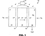
典型的な燃料電池が、図1に示されている。図1に示された燃料電池10は、アノード14に隣接した第1の流体輸送層(FTL)12を含む。電解質膜16がアノード14に隣接している。カソード18が電解質膜16に隣接して位置し、第2の流体輸送層19がカソード18に隣接して位置する。FTL12および19は、拡散集電体(DCC)またはガス拡散層(GDL)と呼ぶことができる。動作中、水素燃料が、燃料電池10のアノード部分に導入され、第1の流体輸送層12を通り、アノード14の上を通る。アノード14において、水素燃料は、水素イオン(H+)と電子(e-)とに分離される。
A typical fuel cell is shown in FIG. The
電解質膜16は、水素イオンまたはプロトンのみが、電解質膜16を通って、燃料電池10のカソード部分に進むことを可能にする。電子は、電解質膜16を通ることができず、代わりに、電流の形態で外部電気回路を通って流れる。この電流は、電気モータなどの電気負荷17を電力供給することができるか、充電式バッテリなどのエネルギー蓄積デバイスに向けることができる。
The
酸素は、第2の流体輸送層19を介して、燃料電池10のカソード側に流入する。酸素がカソード18の上を通るとき、酸素、プロトン、および電子は、組合されて、水および熱を発生する。
Oxygen flows into the cathode side of the
図1に示されたようないくつかの個別の燃料電池を、本発明の原理に従ってロールグッド入力材料(たとえば、燃料電池構成要素のウェブ)から製造することができる。たとえば、個別の燃料電池を、連続組立て方法を用いて製造することができ、ロールグッド入力ウェブ材料を処理して、完成した燃料電池アセンブリのロールグッド出力ウェブを製造する。特定の方法において、ロールグッド入力ウェブ材料を処理して、燃料電池サブアセンブリのロールグッド出力ウェブを製造することができ、これをその後のプロセスで使用して、完成した燃料電池アセンブリを製造することができる。 Several individual fuel cells, such as those shown in FIG. 1, can be manufactured from roll-good input materials (eg, webs of fuel cell components) in accordance with the principles of the present invention. For example, individual fuel cells can be manufactured using a continuous assembly method and the roll-good input web material is processed to produce a roll-good output web of the finished fuel cell assembly. In certain methods, the roll good input web material can be processed to produce a roll good output web of a fuel cell subassembly, which can be used in subsequent processes to produce a finished fuel cell assembly. Can do.
出力燃料電池アセンブリウェブおよびサブアセンブリウェブを適切なライナ材料で巻いて、ロールを形成することができる。別の方法において、出力燃料電池アセンブリウェブおよびサブアセンブリウェブをシンギュレーション(singulation)プロセスにかけることができ、個別の燃料電池アセンブリまたはサブアセンブリがそれらのそれぞれのウェブから分離される。 The output fuel cell assembly web and subassembly web can be wound with a suitable liner material to form a roll. In another method, the output fuel cell assembly web and subassembly web can be subjected to a singulation process, and individual fuel cell assemblies or subassemblies are separated from their respective webs.
他の方法によれば、ロールグッド燃料電池入力ウェブ材料およびフローフィールドプレートを処理して、連続的にユニット化燃料電池アセンブリ(UCA)を製造することができる。ユニット化燃料電池アセンブリは、単独でまたはスタック内の他のUCAと関連して機能燃料電池として働くことができる1つ以上の電池を含むユニットモジュールまたはユニットである。UCAは、モノポーラまたはバイポーラ構成で実現することができる。 According to another method, the roll good fuel cell input web material and the flow field plate can be processed to continuously produce a unitized fuel cell assembly (UCA). A unitized fuel cell assembly is a unit module or unit that includes one or more cells that can act as a functional fuel cell alone or in conjunction with other UCAs in a stack. UCA can be implemented in a monopolar or bipolar configuration.
たとえば、1つの方法において、ロールグッド燃料電池入力ウェブ材料、およびフローフィールドプレートのウェブを処理して、UCAのウェブを製造することができる。フローフィールドプレートのウェブは、インライン成形プロセスを用いて製造することができ、フローフィールドプレートが、燃料電池ウェブ処理の間、前、または後に成形され、かつ、出力ウェブの膜電極アセンブリ(MEA)を収容するために使用される。UCAを、取扱いの容易さおよび今後の使用のために、ロールするか、シンギュレートし積重ねることができる。 For example, in one method, a roll good fuel cell input web material and a web of flow field plates can be processed to produce a UCA web. The flow field plate web can be manufactured using an in-line molding process, wherein the flow field plate is molded during, before or after fuel cell web processing, and the output web membrane electrode assembly (MEA). Used to house. The UCA can be rolled or singulated and stacked for ease of handling and future use.
いくつかの異なった燃料電池技術を用いて、本発明の原理に従う燃料電池アセンブリ、サブアセンブリ、およびUCAを構成することができる。たとえば、本発明の燃料電池製造方法を用いて、プロトン交換膜(PEM)燃料電池アセンブリおよびサブアセンブリを構成することができる。PEM燃料電池は、比較的低温(約175°F/80℃)で動作し、高電力密度を有し、電力要求のシフトに応じるためにそれらの出力を迅速に変えることができ、たとえば自動車におけるような、迅速な始動が必要とされる用途によく適している。 Several different fuel cell technologies can be used to construct fuel cell assemblies, subassemblies, and UCAs in accordance with the principles of the present invention. For example, the fuel cell manufacturing method of the present invention can be used to construct proton exchange membrane (PEM) fuel cell assemblies and subassemblies. PEM fuel cells operate at relatively low temperatures (about 175 ° F / 80 ° C), have high power density, and can quickly change their output to accommodate shifts in power demand, for example in automobiles It is well suited for applications that require rapid start-up.
PEM燃料電池に使用されるプロトン交換膜は、典型的には、水素イオンを通す薄いプラスチックシートである。膜は、典型的には、両側に、活性触媒である高度に分散した金属粒子または金属合金粒子(たとえば、白金または白金/ルテニウム)がコーティングされる。使用される電解質は、典型的には、ポリ−ペルフルオロスルホン酸などの固体有機ポリマーである。固体電解質の使用は、それが腐食問題および管理問題を低減するので、有利である。 Proton exchange membranes used in PEM fuel cells are typically thin plastic sheets that allow hydrogen ions to pass through. The membrane is typically coated on both sides with highly dispersed metal particles or metal alloy particles (eg, platinum or platinum / ruthenium) that are active catalysts. The electrolyte used is typically a solid organic polymer such as poly-perfluorosulfonic acid. The use of a solid electrolyte is advantageous because it reduces corrosion and management problems.
水素が、燃料電池のアノード側に供給され、そこで、触媒は、水素原子が電子を放出して水素イオン(プロトン)になることを促進する。電子は、利用可能な電流の形態で移動し、酸素が導入された燃料電池のカソード側に戻る。同時に、プロトンは、膜を通ってカソードに拡散し、そこで、水素イオンは、酸素と再び組合され反応して、水を生成する。 Hydrogen is supplied to the anode side of the fuel cell where the catalyst promotes the hydrogen atoms to release electrons and become hydrogen ions (protons). The electrons travel in the form of available current and return to the cathode side of the fuel cell where oxygen is introduced. At the same time, protons diffuse through the membrane to the cathode, where the hydrogen ions recombine with oxygen and react to produce water.
膜電極アセンブリ(MEA)は、水素燃料電池などのPEM燃料電池の中心要素である。上述されたように、典型的なMEAは、固体電解質として機能するポリマー電解質膜(PEM)(イオン伝導性膜(ICM)としても知られている)を含む。 A membrane electrode assembly (MEA) is the central element of a PEM fuel cell, such as a hydrogen fuel cell. As mentioned above, a typical MEA includes a polymer electrolyte membrane (PEM) (also known as an ion conductive membrane (ICM)) that functions as a solid electrolyte.
PEMの1つの面はアノード電極層と接触し、反対側の面はカソード電極層と接触する。各電極層は、典型的には白金金属を含む電気化学触媒を含む。流体輸送層(FTL)が、アノード電極材料およびカソード電極材料への、ならびにアノード電極材料およびカソード電極材料からのガス輸送を容易にし、かつ、電流を導く。 One side of the PEM is in contact with the anode electrode layer and the opposite side is in contact with the cathode electrode layer. Each electrode layer typically includes an electrochemical catalyst that includes platinum metal. A fluid transport layer (FTL) facilitates gas transport to and from the anode and cathode electrode materials and conducts current.
典型的なPEM燃料電池において、プロトンが、水素酸化によってアノードで形成され、カソードに輸送されて酸素と反応し、電極を接続する外部回路内で電流が流れることを可能にする。FTLは、また、ガス拡散層(GDL)またはディフューザ/集電体(DCC)と呼んでもよい。アノード電極層およびカソード電極層は、完成されたMEA内でPEMとFTLとの間に配置される限り、製造の間、PEMに塗布してもFTLに塗布してもよい。 In a typical PEM fuel cell, protons are formed at the anode by hydrogen oxidation and transported to the cathode to react with oxygen, allowing current to flow in the external circuit connecting the electrodes. The FTL may also be referred to as a gas diffusion layer (GDL) or a diffuser / current collector (DCC). The anode and cathode electrode layers may be applied to the PEM or FTL during manufacturing as long as they are placed between the PEM and FTL in the completed MEA.
任意の適切なPEMを本発明の実施に使用してもよい。PEMは、典型的には厚さが50μm未満、より典型的には40μm未満、より典型的には30μm未満、最も典型的には約25μmである。PEMは、典型的には、ナフィオン(Nafion)(登録商標)(デラウェア州ウィルミントンのデュポン・ケミカルズ(DuPont Chemicals, Wilmington DE))およびフレミオン(Flemion)(登録商標)(日本、東京の旭硝子株式会社(Asahi Glass Co. Ltd., Tokyo, Japan))などの酸官能性フルオロポリマーであるポリマー電解質から構成される。本発明に有用なポリマー電解質は、典型的には、好ましくはテトラフルオロエチレンと1つ以上のフッ素化酸官能性コモノマーとのコポリマーである。 Any suitable PEM may be used in the practice of the present invention. PEMs typically have a thickness of less than 50 μm, more typically less than 40 μm, more typically less than 30 μm, and most typically about 25 μm. PEMs are typically Nafion® (DuPont Chemicals, Wilmington, DE) and Flemion® (Asahi Glass Co., Tokyo, Japan). (Asahi Glass Co. Ltd., Tokyo, Japan)) and other polymer electrolytes that are acid functional fluoropolymers. The polymer electrolyte useful in the present invention is typically a copolymer of preferably tetrafluoroethylene and one or more fluorinated acid functional comonomers.
典型的には、ポリマー電解質はスルホネート官能基を有する。最も典型的には、ポリマー電解質はナフィオン(登録商標)である。ポリマー電解質は、典型的には酸当量が1200以下、より典型的には1100以下、より典型的には1050以下、最も典型的には約1000である。 Typically, the polymer electrolyte has sulfonate functional groups. Most typically, the polymer electrolyte is Nafion®. The polymer electrolyte typically has an acid equivalent of 1200 or less, more typically 1100 or less, more typically 1050 or less, and most typically about 1000.
任意の適切なFTLを本発明の実施に使用してもよい。典型的には、FTLは、炭素繊維紙などの、炭素繊維を含むシート材料から構成される。FTLは、典型的には、織布および不織布炭素繊維構造から選択される炭素繊維構造である。本発明の実施に有用であろう炭素繊維構造としては、東レ(Toray)カーボン紙、スペクトラカーブ(SpectraCarb)カーボン紙、AFN不織布カーボンクロス、ゾルテック(Zoltek)カーボンクロスなどを挙げてもよい。FTLは、炭素粒子コーティング、親水性化(hydrophilizing)処理、およびポリテトラフルオロエチレン(PTFE)でのコーティングなどの疎水性化(hydrophobizing)処理を含めて、さまざまな材料でコーティングまたは含浸してもよい。 Any suitable FTL may be used in the practice of the present invention. Typically, the FTL is composed of a sheet material that includes carbon fibers, such as carbon fiber paper. The FTL is typically a carbon fiber structure selected from woven and non-woven carbon fiber structures. Carbon fiber structures that may be useful in the practice of the present invention may include Toray carbon paper, SpectraCarb carbon paper, AFN nonwoven carbon cloth, Zoltek carbon cloth, and the like. The FTL may be coated or impregnated with a variety of materials, including carbon particle coatings, hydrophilizing treatments, and hydrophobizing treatments such as coating with polytetrafluoroethylene (PTFE). .
任意の適切な触媒を本発明の実施に使用してもよい。典型的には、炭素担持触媒粒子が使用される。典型的な炭素担持触媒粒子は、50〜90重量%の炭素および10〜50重量%の触媒金属であり、触媒金属は、典型的には、カソード用のPtと、アノード用の2:1の重量比のPtおよびRuとを含む。触媒は、典型的には、触媒インクの形態でPEMまたはFTLに塗布される。触媒インクは、典型的には、PEMを構成するポリマー電解質材料と同じであっても同じでなくてもよいポリマー電解質材料を含む。 Any suitable catalyst may be used in the practice of the present invention. Typically, carbon supported catalyst particles are used. Typical carbon-supported catalyst particles are 50-90 wt% carbon and 10-50 wt% catalyst metal, which is typically 2: 1 Pt for the cathode and 2: 1 for the anode. Containing Pt and Ru in a weight ratio. The catalyst is typically applied to the PEM or FTL in the form of a catalyst ink. The catalyst ink typically includes a polymer electrolyte material that may or may not be the same as the polymer electrolyte material that comprises the PEM.
触媒インクは、典型的には、ポリマー電解質の分散液中の触媒粒子の分散液を含む。インクは、典型的には5〜30%の固形分(すなわちポリマーおよび触媒)、より典型的には10〜20%の固形分を含有する。電解質分散液は、典型的には水性分散液であり、これは、アルコール、グリセリンおよびエチレングリコールなどの多価アルコール、またはN−メチルピロリドン(methylpyrolidone)(NMP)およびジメチルホルムアミド(DMF)などの他の溶媒をさらに含有してもよい。水、アルコール、および多価アルコール含有量は、インクのレオロジー特性を変更するように調整してもよい。インクは、典型的には、0〜50%のアルコールおよび0〜20%の多価アルコールを含有する。さらに、インクは適切な分散剤0〜2%を含有してもよい。インクは、典型的には、熱とともに撹拌し、その後、コーティング可能なコンシステンシーに希釈することによって製造される。 The catalyst ink typically comprises a dispersion of catalyst particles in a dispersion of polymer electrolyte. The ink typically contains 5-30% solids (ie polymer and catalyst), more typically 10-20% solids. The electrolyte dispersion is typically an aqueous dispersion, which may be an alcohol, a polyhydric alcohol such as glycerin and ethylene glycol, or other such as N-methylpyrrolidone (NMP) and dimethylformamide (DMF). These solvents may be further contained. Water, alcohol, and polyhydric alcohol content may be adjusted to alter the rheological properties of the ink. The ink typically contains 0-50% alcohol and 0-20% polyhydric alcohol. In addition, the ink may contain 0-2% of a suitable dispersant. Inks are typically made by stirring with heat and then diluting to a coatable consistency.
触媒は、アノード配合物およびカソード配合物の両方の、ハンドブラッシング、ノッチバーコーティング、流体ベアリング(fluid bearing)ダイコーティング、巻線ロッドコーティング、流体ベアリングコーティング、スロット供給ナイフコーティング、3ロールコーティング、または、乾燥した触媒コーティングの、膜上へのデカール転写を含む、手動方法および機械方法の両方を含む任意の適切な手段によって、PEMまたはFTLに塗布してもよい。コーティングは、1回の塗布または複数回の塗布で行ってもよい。 The catalyst can be hand brushed, notched bar coated, fluid bearing die coated, wound rod coated, fluid bearing coated, slot fed knife coated, three roll coated, or both anode and cathode formulations, The dried catalyst coating may be applied to the PEM or FTL by any suitable means including both manual and mechanical methods, including decal transfer onto the membrane. The coating may be performed by a single application or multiple applications.
本発明の原理に従う燃料電池アセンブリ、サブアセンブリ、およびUCAを構成するために用いることができる別の燃料電池技術は、ダイレクトメタノール燃料電池と呼ばれる。ダイレクトメタノール燃料電池(DMFC)は、ポリマー膜を電解質として使用する点で、PEM電池と同様である。しかし、DMFCにおいて、アノード触媒自体が、液体メタノール燃料から水素を引き、燃料改質装置の必要をなくす。DMFCは、典型的には、120〜190°F/49〜88℃の間の温度で動作する。ダイレクトメタノール燃料電池は、本発明の原理に従う処理およびパッケージングを行うことができる。 Another fuel cell technology that can be used to construct fuel cell assemblies, subassemblies, and UCAs in accordance with the principles of the present invention is referred to as a direct methanol fuel cell. Direct methanol fuel cells (DMFC) are similar to PEM cells in that they use a polymer membrane as the electrolyte. However, in the DMFC, the anode catalyst itself draws hydrogen from the liquid methanol fuel, eliminating the need for a fuel reformer. DMFCs typically operate at temperatures between 120-190 ° F / 49-88 ° C. Direct methanol fuel cells can be processed and packaged according to the principles of the present invention.
ここで、図2を参照すると、PEM燃料電池技術に従う多層燃料電池37の実施形態が示されている。図2の燃料電池実施形態の断面図が図3に提供されている。図2および図3に示された燃料電池37は、5層MEA構造と、2層ガスケット構造とを含む7層構造である。
Referring now to FIG. 2, an embodiment of a
燃料電池37は、接合層32および42がそれぞれ塗布された表面を有するPEM層30を含む。接合層32および42は、図2において別々の部材として示されているが、接合層32および42を、固体、液体、またはUVもしくは光硬化性材料または蒸気接合材料もしくは蒸気接合剤を使用して形成することができることが理解される。
The
接合層32および42は、PEM層30の活性領域にほぼ等しいサイズを有する窓を含むように、パターニングまたは他の態様で形成される。接合層32および42の窓は、いくつかの内方に延在する接合サイト33、43を含む。接合サイト33、43は、PEM層30の活性領域内に延在し、かつ、PEM層30の活性領域内への接合層32および42の進入を最小にしながら、PEM層30の活性領域とそれぞれの流体輸送層(FTL)36および46との間の接着接触を容易にするのに役立つ。接合サイトを使用して、PEM層30とFTL36および46との間の接着接触を提供することは、有利に、これらの層に、従来の処理技術の場合のように高温で長時間圧縮プレス力をかける必要をなくすことができる。
Bonding layers 32 and 42 are patterned or otherwise formed to include windows having a size approximately equal to the active area of
図2において、接合サイト33、43は、接合層窓の内周に設けられた一連の突出部または指として示されている。接合サイトを、いくつかの異なった構成を呈するように形成またはパターニングすることができ、また、図2および他のところに示された指形接合サイト33、43が、例示的な、非限定的な目的のためにすぎないことが理解される。たとえば、接合サイト33、43は、接合層窓の内周のいくつかの端縁部分を画定することができる。また、接合サイト33、43は、接合層窓の連続内周縁を画定することができる。これらおよび他の構成を、接合サイト33、43として使用することができ、そのような接合サイトは、約15%以下などの、PEM層30の総活性領域の小さいパーセンテージのみと接触する。
In FIG. 2, the
ガスケット層34および44は、それぞれの接合層32および42と接触するように位置する。ガスケット層34および44は、接合層32および42の窓より大きいサイズを有する窓を含む。ガスケット層34および44は、たとえば、テフロン(登録商標)(TEFLON(登録商標))、テフロン(登録商標)で含浸されたガラス繊維、エラストマー材料、UV硬化性ポリマー材料、表面テクスチャー材料、多層複合材料、シーラント、およびシリコン材料を含むさまざまな材料から形成することができる。 The gasket layers 34 and 44 are located in contact with the respective bonding layers 32 and 42. The gasket layers 34 and 44 include windows having a larger size than the windows of the bonding layers 32 and 42. The gasket layers 34 and 44 are made of, for example, Teflon (registered trademark), glass fiber impregnated with Teflon (registered trademark), elastomer material, UV curable polymer material, surface texture material, multilayer composite material. , Sealants, and silicon materials.
1つの特定の実施形態において、ガスケット層34および44は、各々、代理人事件番号58218US002で2002年11月14日に出願された同時係属中の出願第10/294,098号明細書に開示されたような独立気泡フォームゴムガスケットであってもよい。他の実施形態において、ガスケット層34および44には、2002年5月10日に出願された同時係属中の出願第10/143,273号明細書に開示されたような隆起リッジ微細構造化シーリングパターンを有する接触面を形成してもよい。 In one particular embodiment, gasket layers 34 and 44 are each disclosed in co-pending application Ser. No. 10 / 294,098 filed Nov. 14, 2002, with agent case number 58218US002. Such a closed cell foam rubber gasket may be used. In other embodiments, the gasket layers 34 and 44 include raised ridge microstructured sealing as disclosed in copending application Ser. No. 10 / 143,273 filed on May 10, 2002. A contact surface having a pattern may be formed.
FTL36および46は、ガスケット層34および44の窓内に嵌合するようなサイズである。さらに、FTL36および46は、接合サイト33および43を被覆することに加えて、接合層32および42の窓の内周縁を被覆するようなサイズである。アノード触媒材料(図示せず)が、2つのFTL36、46の一方とPEM層30との間に位置し、カソード触媒材料(図示せず)が、PEM層30と2つのFTL36、46の他方との間に位置する。
FTLs 36 and 46 are sized to fit within the windows of gasket layers 34 and 44. Further, the
1つの構成において、PEM層30は、一方の表面上にアノード触媒コーティングを含み、他方の表面上にカソード触媒コーティングを含むように製造される。この構造は、しばしば、触媒コーティング膜またはCCMと呼ばれる。別の構成によれば、FTL36、46は、それぞれ、アノード触媒コーティングおよびカソード触媒コーティングを含むように製造される。さらに別の構成において、アノード触媒コーティングを、2つのFTL36、46の一方の上に部分的に配置し、かつPEM層30の一方の表面上に部分的に配置することができ、カソード触媒コーティングを、2つのFTL36、46の他方の上に部分的に配置し、かつPEM層30の他方の表面上に部分的に配置することができる。
In one configuration, the
PEM層30ならびにFTL36および46は、上述されたような構造を有することができる。接合層32および42は、熱硬化性または熱可塑性材料などの熱接合材料を使用して形成することができる。適切な接合層材料としては、感圧接着剤、接合剤、セルフシーリング材料、および熱活性化接合材料が挙げられる。
The
一実施形態によれば、接合層32および46は、熱可塑性シーリング材料を使用して形成される。熱可塑性樹脂は、THV(テトラフルオロエチレンと、ヘキサフルオロプロピレンと、二フッ化ビニリデンとのターポリマー)などのフッ素樹脂、ポリエチレン、エチレンとアクリル酸とのコポリマーなどのポリエチレンのコポリマー、サーモボンド(Thermo−Bond)845(3Mによって製造される、たとえば、ポリエチレン無水マレイン酸コポリマー)およびサーモボンド668(3Mによって製造される、たとえば、ポリエステル)であることができる。これらの材料またはこれらの複合材料と、炭素、ガラス、セラミックなどの充填剤とのブレンドも、熱可塑性樹脂として使用してもよい。好ましくは、溶融範囲は50〜180℃であり、より好ましくは100〜150℃であり、これは、MEA接合温度と同様でなければならない。 According to one embodiment, the bonding layers 32 and 46 are formed using a thermoplastic sealing material. Thermoplastic resins include fluoropolymers such as THV (terpolymer of tetrafluoroethylene, hexafluoropropylene and vinylidene difluoride), polyethylene, copolymers of polyethylene such as copolymers of ethylene and acrylic acid, Thermobond (Thermo -Bond) 845 (manufactured by 3M, for example polyethylene maleic anhydride copolymer) and Thermobond 668 (manufactured by 3M, for example polyester). Blends of these materials or their composite materials with fillers such as carbon, glass, ceramics may also be used as the thermoplastic resin. Preferably, the melting range is 50-180 ° C, more preferably 100-150 ° C, which should be similar to the MEA bonding temperature.
図4は、本発明の実施形態による燃料電池サブアセンブリ35の図である。図4に示された燃料電池サブアセンブリ35は、膜の対向する表面上に接合層を組入れる独自の5層MEA構造である。示されているように、図4のMEAは、図2および図3の燃料電池アセンブリと関連して先に説明された層および特徴のいくつかを組入れる。特に、図4のMEAは、接合層32および42がそれぞれ塗布された表面を有するPEM層30を含む。先に説明されたように、接合層32および42は、PEM層30の活性領域にほぼ等しいサイズを有する窓を含む。
FIG. 4 is a diagram of a
接合層32および42の窓は、いくつかの内方に延在する接合サイトまたは指33、43を含む。接合サイト33、43は、PEM層30の活性領域内に延在し、かつPEM層30の活性領域の部分ならびにそれぞれの流体輸送層(FTL)36および46と接着接触する。FTL36および46は、ガスケット層34および44の窓内に嵌合し、かつ、接合サイト33および43を被覆することに加えて、接合層32および42の窓の内周縁を被覆するようなサイズである。アノードが、2つのFTL36、46の一方とPEM層30との間に位置し、カソードが、PEM層30と2つのFTL36、46の他方との間に位置する。
The windows of the bonding layers 32 and 42 include several inwardly extending bonding sites or
この実施形態において、PEM層30と接触していない接合層32、42の表面は、好ましくは、ライナ(図示せず)または他の材料によって被覆され、接合層32、42の接合材料およびFTL36、46は、それらの露出がその後のプロセスにおいて望ましいような時まで露出されない。さまざまなタイプの剥離ライナをこの目的で使用することができる。その後のプロセスにおいて、露出された接合層32、42およびFTL36、46を、たとえば、それぞれのガスケット層またはフローフィールドプレートと位置合せしてもよい。
In this embodiment, the surfaces of the bonding layers 32, 42 that are not in contact with the
図4に示されたタイプのMEA構造は、ロールグッドの形態またはスタックなど、その後の燃料電池製造プロセスでの使用のための適切な態様で保管することができる。あるいは、これらのMEA構造を、以下で説明されるような、さらなる自動化燃料電池組立てプロセスにかけることができる。上述されたように剥離ライナが使用される場合、剥離ライナを、自動化プロセスなどによって、接合層/FTLの外面から除去することができる。特定の熱接合材料を組入れる燃料電池アセンブリロールグッドの場合など、特定の接合材料を、ライナを使用して保護する必要がないことが認められる。 An MEA structure of the type shown in FIG. 4 can be stored in a suitable manner for use in subsequent fuel cell manufacturing processes, such as a roll-good form or stack. Alternatively, these MEA structures can be subjected to further automated fuel cell assembly processes as described below. If a release liner is used as described above, the release liner can be removed from the outer surface of the bonding layer / FTL, such as by an automated process. It will be appreciated that certain bonding materials need not be protected using a liner, such as in the case of a fuel cell assembly roll-good that incorporates certain thermal bonding materials.
例として、図5を参照すると、上述されたタイプのMEA35が1対のフローフィールドプレート50および60の間に配置されたUCAの実施形態が示されている。この実施形態によれば、MEA35は、各々が、先に説明されたように、PEM層30の活性領域にサイズがほぼ等しい窓と、内方に延在する接合サイトまたは指33、43とを有する接合層32および42の間に挟まれたPEM層30を含む。2つのFTL36および46は、ガスケット層34および44の窓内に嵌合し、かつ、接合サイト33および43を被覆することに加えて、接合層32および42の窓の内周縁を被覆するようなサイズである。先に説明されたように、アノード領域およびカソード領域が、それぞれ、2つのFTL36、46とPEM層30との間に位置する。
As an example, referring to FIG. 5, an embodiment of a UCA in which an
図5に示された接合層32および42の各々は、それぞれのフローフィールドプレート50、60の表面と位置合せすることができる露出された接合表面を有する。接合層32および42の露出された接合表面、ならびにそれぞれのフローフィールドプレート50および60の間の接合接触は、有利に、自動化燃料電池組立ての間、これらの構成要素の間の正確な位置合せを維持する。さらに、接合層32および42は、ヒートシーリングプロセスの間、UCAの端縁シーリングを容易にすることができる。本発明のプロセスおよび構造特徴を組入れてもよいUCA製造プロセスおよび構造は、2002年11月15日に同時に出願された同時係属中の出願第10/295,518号明細書および第10/295,292号明細書に開示されている。
Each of the bonding layers 32 and 42 shown in FIG. 5 has an exposed bonding surface that can be aligned with the surface of the respective
一般的に言うと、フローフィールドプレート50、60の各々は、水素および酸素供給燃料が通るポートおよびガスフローチャネルのフィールドを含む。特定の構成において、フローフィールドプレート50、60は、モノポーラフローフィールドプレートとして構成することができ、1つのMEA35が1対のフローフィールドプレート50、60の間に挟まれてUCAを画定する。このおよび他の実施形態のフローフィールドは、2001年9月17日に出願された同時係属中の出願第09/954,601号明細書に開示されたような低横流(low lateral flux)フローフィールドであってもよい。典型的な構成において、フローフィールドプレートのサイズは、典型的には、膜とほぼ同じサイズである。
Generally speaking, each of the
他の構成において、UCAが、1つ以上のバイポーラフローフィールドプレートの使用によって複数のMEA35を組入れることができる。たとえば、UCAが、図5に記載されたタイプの2つのMEA35と、1つのバイポーラフローフィールドプレートとを組入れることができる。そのような構成において、第1のMEA35が、第1のFTLと第2のFTLとの間に挟まれた接合層/カソード/膜/アノード/接合層構造を含むことができる。第1のFTLは、モノポーラフローフィールドプレートとして構成することができる第1のフローフィールドエンドプレートに隣接して位置することができる。第2のFTLは、バイポーラフローフィールドプレートの第1のフローフィールド表面に隣接して位置することができる。
In other configurations, a UCA can incorporate
同様に、第2のMEA35が、第3のFTLと第4のFTLとの間に挟まれた接合層/カソード/膜/アノード/接合層構造を含むことができる。第3のFTLは、モノポーラフローフィールドプレートとして構成することができるフローフィールドエンドプレートに隣接して位置することができる。第4のFTLは、バイポーラフローフィールドプレートの第2のフローフィールド表面に隣接して位置することができる。N数のMEA35およびN−1のバイポーラフローフィールドプレートを、1つのUCAに組入れることができることが理解されるであろう。しかし、一般に、1つまたは2つのMEA35を組入れるUCAが、より効率的な熱管理に好ましいと考えられる。
Similarly, the
図5に示されここで説明されるUCA構成は、本発明に関連する使用のために実現することができる特定の機構を表す。これらの機構は、例示のためにのみ提供され、本発明の範囲内になる可能な構成をすべて表すことが意図されない。たとえば、以下で説明されるようなフローフィールドプレートを製造するためのインライン成形プロセスが、付加的なまたは向上したシーリング特徴、ガスケット特徴、および/またはハードストップ特徴およびソフトストップ特徴などの特定のUCA特徴の使用を決定してもよい。逆に、そのようなインライン成形プロセスは、フローフィールドプレートのマニホルドの周りに成形された材料の代わりの使用によって別個のガスケット特徴またはシーリング特徴をなくすことなどの、特定のUCA特徴をなくすことに備えてもよい。 The UCA configuration shown in FIG. 5 and described herein represents a particular mechanism that can be implemented for use in connection with the present invention. These features are provided for illustration only and are not intended to represent all possible configurations that are within the scope of the invention. For example, an in-line molding process for manufacturing a flow field plate as described below may include additional or improved sealing features, gasket features, and / or certain UCA features such as hard and soft stop features. You may decide to use Conversely, such an in-line molding process provides for the elimination of certain UCA features, such as the elimination of discrete gasket or sealing features through the use of alternative materials molded around the manifold of the flow field plate. May be.
さらなる例として、さまざまな向上したシーリング方法を用いて、1対のモノポーラフローフィールドプレートの間に配置された1つのMEAを含むUCAの必要なシーリングを提供することができ、また、複数のMEAと、1対のモノポーラフローフィールドプレートと、1つ以上のバイポーラフローフィールドプレートとを含むUCAをシールすることができる。たとえば、モノポーラ構造またはバイポーラ構造を有するUCAを、先に援用された出願第10/295,518号明細書および第10/295,292号明細書に開示された平坦な固体シリコーンガスケットなどの、その場で形成された固体ガスケットを含むように構成することができる。
As a further example, various improved sealing methods can be used to provide the required sealing of a UCA that includes a single MEA disposed between a pair of monopolar flow field plates, A UCA that includes a pair of monopolar flow field plates and one or more bipolar flow field plates can be sealed. For example, a UCA having a monopolar or bipolar structure may be used such as a flat solid silicone gasket disclosed in previously incorporated
特定の実施形態において、UCAはさらに、ハードストップ機構を含むことができる。ハードストップは、組込むか、UCAの内部に配置するか、モノポーラおよび/またはバイポーラフローフィールドプレートに一体化することができる。フローフィールドプレート上に設けられた微細複製パターンおよび余分なガスケット材料のトラップチャネルなどの他の特徴を、UCAに組入れることができる。ハードストップをUCAパッケージングに組入れることは、有利に、製造の間(たとえば、プレス力)および使用の間(たとえば、外部スタック圧力システム)にMEAに加えられる圧縮力の量を制限する。たとえば、UCAハードストップの高さを計算して、UCA構成の間、30%などの指定された量のMEA圧縮をもたらすことができ、そのような圧縮は、ハードストップによって、指定された量に制限される。ハードストップをフローフィールドプレートに組入れることは、また、2つのフローフィールドプレートのための位置合せの助けとして働くことができる。 In certain embodiments, the UCA can further include a hard stop mechanism. The hard stop can be incorporated, placed inside the UCA, or integrated into a monopolar and / or bipolar flow field plate. Other features, such as microreplicated patterns provided on the flow field plate and trap channels of excess gasket material can be incorporated into the UCA. Incorporating hard stops into UCA packaging advantageously limits the amount of compressive force applied to the MEA during manufacturing (eg, pressing force) and use (eg, external stack pressure system). For example, the height of a UCA hard stop can be calculated to provide a specified amount of MEA compression, such as 30%, during UCA configuration, such compression can be reduced to a specified amount by a hard stop. Limited. Incorporating a hard stop into the flow field plate can also serve as an alignment aid for the two flow field plates.
さらに、さまざまなUCA構成を、本発明の他の実施形態による熱管理能力で実現することができる。例として、所与のUCA構成が、一体化熱管理システムを組入れることができる。あるいは、またはさらに、所与のUCAを、分離可能な熱管理構造と機械的に結合するように構成することができる。いくつかの例示的なUCAハードストップおよび熱管理方法が、先に援用された出願第10/295,518号明細書および第10/295,292号明細書に開示されている。
Further, various UCA configurations can be realized with thermal management capabilities according to other embodiments of the present invention. As an example, a given UCA configuration can incorporate an integrated thermal management system. Alternatively or additionally, a given UCA can be configured to mechanically couple with a separable thermal management structure. Several exemplary UCA hardstop and thermal management methods are disclosed in previously incorporated
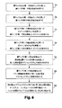
図6〜9は、本発明の実施形態によって燃料電池アセンブリおよびサブアセンブリを製造することができるさまざまな方法を示す。図6は、ロールグッド入力燃料電池材料を使用する、MEAなどの、ロールグッド燃料電池サブアセンブリまたはシンギュレートされた燃料電池サブアセンブリの連続製造を伴うさまざまなプロセスを示す。図6の実施形態によれば、PEM材料のウェブなどの膜材料のウェブが、接合材料の第1のウェブとともに処理されて(70)、膜ウェブの第1の接合表面を形成する。膜ウェブの第2の表面が、第2の接合材料ウェブとともに処理されて(72)、膜ウェブの第2の接合表面を形成する。 6-9 illustrate various methods by which fuel cell assemblies and subassemblies can be manufactured according to embodiments of the present invention. FIG. 6 illustrates various processes involving continuous production of a roll good fuel cell subassembly or singulated fuel cell subassembly, such as an MEA, using a roll good input fuel cell material. According to the embodiment of FIG. 6, a web of membrane material, such as a web of PEM material, is treated (70) with a first web of joining material to form a first joining surface of the membrane web. The second surface of the membrane web is treated (72) with the second bonding material web to form the second bonding surface of the membrane web.
膜ウェブの第1の接合表面は、ガスケット材料の第1のウェブとともに処理されて(74)、膜ウェブの第1の接合表面上にガスケットを形成する。膜ウェブの第2の接合表面は、第2のガスケット材料ウェブとともに処理されて(76)、膜ウェブの第2の接合表面上にガスケットを形成する。 The first joining surface of the membrane web is treated (74) with the first web of gasket material to form a gasket on the first joining surface of the membrane web. The second joining surface of the membrane web is treated (76) with the second gasket material web to form a gasket on the second joining surface of the membrane web.
膜ウェブの第1の接合表面は、FTL材料部分とともにさらに処理されて(78)、第1の燃料電池サブアセンブリウェブ表面を形成する。膜ウェブの第2の接合表面は、FTL材料部分とともに処理されて(80)、第2の燃料電池サブアセンブリウェブ表面を形成する。 The first joining surface of the membrane web is further processed (78) with the FTL material portion to form a first fuel cell subassembly web surface. The second bonding surface of the membrane web is treated (80) with the FTL material portion to form a second fuel cell subassembly web surface.
FTL材料部分は、好ましくは、第1および第2のFTL材料ウェブから提供され、これらは、膜ウェブの第1および第2の接合表面とともに処理されて、それぞれ、第1および第2の燃料電池サブアセンブリウェブ表面を形成する。膜ウェブの第1および第2の表面上に形成された第1および第2の燃料電池サブアセンブリウェブ表面は、図2〜3にMEA37として示されたようなMEA構造のウェブを画定する。
The FTL material portion is preferably provided from first and second FTL material webs that are treated with the first and second joining surfaces of the membrane web to provide first and second fuel cells, respectively. Forming a sub-assembly web surface; The first and second fuel cell subassembly web surfaces formed on the first and second surfaces of the membrane web define a web of MEA structure as shown as
燃料電池サブアセンブリウェブは、燃料電池サブアセンブリロールグッドを製造するための巻きプロセス、またはシンギュレートされた燃料電池サブアセンブリシートを製造するためのシンギュレーションプロセスなどへ、さらなる処理のために移送される(82)。取扱いおよび輸送性を向上させるため、ライナが、典型的には、膜ウェブ表面の他の露出された接合材料表面と接触することが認められる。 The fuel cell subassembly web is transferred for further processing, such as to a winding process to produce a fuel cell subassembly roll good, or to a singulation process to produce a singulated fuel cell subassembly sheet (82). In order to improve handling and transportability, it is recognized that the liner typically contacts other exposed bonding material surfaces of the membrane web surface.
図7は、別の実施形態によって、MEAなどの燃料電池サブアセンブリのウェブを製造するためのさまざまなプロセスを示す。この方法によれば、各々が窓付セクションを備えた第1および第2の接合材料ウェブが提供される(90)。ライナが、それぞれ、第1および第2の接合表面の一方の表面上に設けられる。窓付の第1および第2の接合材料ウェブの露出された表面が、膜ウェブの第1および第2の表面に積層される(92)。FTL材料部分が、接合材料ウェブの窓内の露出された接合サイトと接触するように、膜ウェブの活性領域に位置決めされる(94)。 FIG. 7 illustrates various processes for manufacturing a web of fuel cell subassemblies such as MEAs, according to another embodiment. According to this method, first and second joining material webs are provided 90 each having a windowed section. A liner is provided on one of the first and second joining surfaces, respectively. The exposed surfaces of the windowed first and second bonding material webs are laminated (92) to the first and second surfaces of the membrane web. The FTL material portion is positioned (94) in the active area of the membrane web such that it contacts the exposed bond sites in the window of the bond material web.
次に、FTL材料部分は、膜ウェブの第1および第2の表面の活性領域に積層され(96)、したがって、図4にMEA35として示されたようなMEA構造のウェブを形成する。多層燃料電池サブアセンブリウェブは、さらに処理されて(98)、燃料電池サブアセンブリロールグッドまたはシンギュレートされた燃料電池サブアセンブリシートを製造する。
The FTL material portion is then laminated (96) to the active areas of the first and second surfaces of the membrane web, thus forming a MEA structured web, such as shown as
図8は、本発明のさらなる実施形態によって、ガスケット層を組入れる燃料電池サブアセンブリのウェブを製造するためのさまざまなプロセスを示す。この実施形態によれば、第1および第2の接合材料ウェブの窓は、膜ウェブの活性領域と整列される(100)。窓付の第1および第2の接合材料ウェブは、膜ウェブのそれぞれの第1および第2の表面に積層される(102)。第3および第4のガスケット材料ウェブの窓は、膜ウェブの第1および第2の活性領域と整列される(104)。第3および第4の窓付ガスケット材料ウェブは、第1および第2の膜ウェブ表面上の接合材料に積層される(106)。 FIG. 8 illustrates various processes for producing a web of fuel cell subassemblies incorporating a gasket layer, according to further embodiments of the present invention. According to this embodiment, the windows of the first and second bonding material webs are aligned with the active area of the membrane web (100). First and second bonding material webs with windows are laminated (102) to the respective first and second surfaces of the membrane web. The windows of the third and fourth gasket material webs are aligned (104) with the first and second active areas of the membrane web. The third and fourth windowed gasket material webs are laminated to the bonding material on the first and second membrane web surfaces (106).
FTL材料部分が、第1および第2の接合材料ウェブの窓内に画定された接合サイトと接触するように、第1および第2の膜ウェブ表面の活性領域に位置決めされる(108)。次に、FTL材料部分は、第1および第2の膜ウェブ表面の活性領域に積層される(110)。図8に示されたプロセスを用いて、図2および図3に示されたMEA37などの、ガスケット材料層を組入れるMEAを製造することができる。先の実施形態のように、図8に従って製造された多層燃料電池サブアセンブリウェブを、さらに処理して、燃料電池サブアセンブリロールグッドまたはシンギュレートされた燃料電池サブアセンブリシートを製造することができる。
A portion of the FTL material is positioned 108 in the active region of the first and second membrane web surfaces so as to contact the bond sites defined in the windows of the first and second bond material webs. Next, the FTL material portion is laminated to the active regions of the first and second membrane web surfaces (110). The process shown in FIG. 8 can be used to manufacture an MEA that incorporates a gasket material layer, such as
図9は、本発明の実施形態によるユニット化燃料電池アセンブリまたはUCAの製造を伴うさまざまなプロセスを示す。この方法によれば、膜ウェブ、第1の接合材料ウェブ、および第1のFTLウェブが、処理されて(120)、燃料電池サブアセンブリウェブの第1の表面を形成する。膜ウェブ、第2の接合材料ウェブ、および第2のFTLウェブが、処理されて(122)、燃料電池サブアセンブリウェブの第2の表面を形成する。 FIG. 9 illustrates various processes involving the manufacture of unitized fuel cell assemblies or UCAs according to embodiments of the invention. According to this method, the membrane web, the first bonding material web, and the first FTL web are processed (120) to form a first surface of the fuel cell subassembly web. The membrane web, the second bonding material web, and the second FTL web are processed (122) to form a second surface of the fuel cell subassembly web.
一連の第1のフローフィールドプレート(たとえば、モノポーラまたはバイポーラ)が、燃料電池サブアセンブリウェブの第1の表面と接触するために位置決めされる(124)。一連の第2のフローフィールドプレートが、燃料電池サブアセンブリウェブの第2の表面と接触するために位置決めされる(126)。特に、対の第1および第2のフローフィールドプレートが、燃料電池サブアセンブリウェブ上に形成された個別の燃料電池サブアセンブリと接触するために位置決めされる。対の第1および第2のフローフィールドプレートならびに個別の燃料電池サブアセンブリは、処理されて(128)、UCAのウェブなどのユニット化燃料アセンブリを形成する。 A series of first flow field plates (eg, monopolar or bipolar) are positioned to contact the first surface of the fuel cell subassembly web (124). A series of second flow field plates are positioned for contact with the second surface of the fuel cell subassembly web (126). In particular, a pair of first and second flow field plates are positioned for contact with individual fuel cell subassemblies formed on the fuel cell subassembly web. The pair of first and second flow field plates and the individual fuel cell subassemblies are processed (128) to form a unitized fuel assembly such as a UCA web.
ウェブ形態またはシンギュレートされた形態のUCAを、加熱プレス手順などを用いることによって、さらに処理して、個別のUCAをシールすることができる。図9に示されたプロセスを用いて、図5に示されたタイプのUCAを製造することができる。そのようなUCAのウェブをさらに処理して、UCAロールグッドまたはシンギュレートされたUCAを製造することができる。 The web form or singulated form of UCA can be further processed to seal individual UCAs, such as by using a hot press procedure. The process shown in FIG. 9 can be used to produce a UCA of the type shown in FIG. Such UCA webs can be further processed to produce UCA roll-good or singulated UCA.
上述されたプロセスは、例示のためにのみ提供され、本発明の範囲内になる、燃料電池アセンブリ、サブアセンブリ、およびUCAを製造するための可能なプロセスをすべて表すことが意図されない。さらに、上述されたものに加えて、または上述されたものと異なった、プロセスを用いて、本発明の燃料電池アセンブリ、サブアセンブリ、およびUCAを製造することができる。たとえば、以下で説明される装置および関連したプロセスを用いて、本発明の燃料電池アセンブリ、サブアセンブリ、およびUCAを製造することができる。 The processes described above are provided for illustration only and are not intended to represent all possible processes for manufacturing fuel cell assemblies, subassemblies, and UCAs that are within the scope of the present invention. In addition, processes in addition to or different from those described above can be used to manufacture the fuel cell assemblies, subassemblies, and UCAs of the present invention. For example, the apparatus and associated processes described below can be used to manufacture the fuel cell assemblies, subassemblies, and UCAs of the present invention.
ここで図10〜図12を参照すると、燃料電池材料の入力ウェブを処理し、そのような入力ウェブから、燃料電池アセンブリ、サブアセンブリ、またはUCAの出力ロールグッドを製造する装置が示されている。一般的に言うと、図10〜図12の装置は、ロールグッド燃料電池構成要素を使用する燃料電池のロールグッドを製造することができる。図10の装置は、連続燃料電池製造プロセスにおいて、イオノマー燃料電池膜ウェブに、ガスケットおよびFTL構成要素などのさまざまな燃料電池構成要素を付着する目的で、イオノマー燃料電池膜ウェブを準備するための独自の方法を提供する。図11の装置は、連続燃料電池製造プロセスにおいて、FTL材料ウェブから切断されたFTL材料部分を、準備された膜に付着するための独自の方法を提供する。図12は、図10および図11の装置を含む1つの装置を示す。 Referring now to FIGS. 10-12, there is shown an apparatus for processing an input web of fuel cell material and producing a fuel cell assembly, subassembly, or UCA output rollgood from such input web. . Generally speaking, the apparatus of FIGS. 10-12 can produce a fuel cell roll-good that uses roll-good fuel cell components. The apparatus of FIG. 10 is unique for preparing an ionomer fuel cell membrane web for the purpose of attaching various fuel cell components such as gaskets and FTL components to the ionomer fuel cell membrane web in a continuous fuel cell manufacturing process. Provide a way. The apparatus of FIG. 11 provides a unique method for attaching a portion of FTL material cut from an FTL material web to a prepared membrane in a continuous fuel cell manufacturing process. FIG. 12 shows one apparatus that includes the apparatus of FIGS.
図10の装置は、ライナからのパターニングされた接合剤を、燃料電池膜ウェブに積層する。接合材料パターンは、好ましくは、燃料電池膜ウェブの触媒活性領域と実質的に同じ形状および領域を有する。さらに、一実施形態によれば、準備後、ガスケット材料が燃料電池膜ウェブに付着される。これは、燃料電池構成要素の連続組立てに必要な優れた膜ウェブ安定性に寄与する。接合材料は、典型的には、厚さが約25〜152μm(約1〜6ミル)である。 The apparatus of FIG. 10 laminates a patterned binder from a liner to a fuel cell membrane web. The bonding material pattern preferably has substantially the same shape and area as the catalytically active area of the fuel cell membrane web. Further, according to one embodiment, after preparation, a gasket material is attached to the fuel cell membrane web. This contributes to the excellent membrane web stability required for continuous assembly of fuel cell components. The bonding material typically has a thickness of about 25-152 μm (about 1-6 mils).
図10に示されているように、ライナ上の接合材料の第1のロール212aが、回転ダイ234aおよびアンビルロール240aによってダイカットされて、接合材料のパターニングされた(たとえば、窓付の)ウェブが製造される。ライナ上の廃棄接合材料218aが、真空プロセスなどによって収集される。パターニングされた接合材料ウェブ212aは、ニップロール238aによって膜ウェブ210の頂面に積層される。したがって、積層された膜ウェブは、その頂面222上にパターニングされた接合剤およびライナを有する。
As shown in FIG. 10, a
ライナ上の接合材料の第2のロール212bも、回転ダイ234bおよびアンビルロール240bによってダイカットされ、ニップロール238bによって膜ウェブ210の底面に積層され、ライナ/接合材料/膜/接合材料/ライナ構造224をもたらす。ライナ上の廃棄接合材料218bは収集される。
A
光学センサが、好ましくは、膜ウェブ210の頂面および底面の両方の上の接合材料ウェブパターン(たとえば、窓)を整列させるために使用される。光ファイバセンサは、たとえば、膜ウェブ210の両側の活性領域に対して接合材料パターンの窓を検出することができる。
An optical sensor is preferably used to align the bonding material web pattern (eg, window) on both the top and bottom surfaces of the
当業者は、いくつかの技術および構成を用いて、光学センサまたは他のタイプの検知機構を使用する窓付材料の整列を容易にできることを理解するであろう。例として、ダイ234aから切断されたパターンを、それがロール240aおよび238aによって形成されたニップにおいて積層された後、かつロール240bおよび238bによって形成されたニップ前に検出するように、1つの光学センサを位置決めすることができる。ダイロール234b上のまたはダイロール234bに付着されたマークを検出するように、第2の光学センサを位置決めすることができ、マークは各ダイキャビティに対応する。
Those skilled in the art will appreciate that several techniques and configurations can be used to facilitate alignment of windowed materials using optical sensors or other types of sensing mechanisms. As an example, one optical sensor to detect a pattern cut from
別の光学検知方法は、ダイロール234a上のまたはダイロール234aに付着されたマークを検出するように、第1のセンサを位置決めすることを伴い、マークは各キャビティに対応し、かつ、ダイロール234b上のまたはダイロール234bに付着されたマークを検出するように、第2のセンサを位置決めすることを伴い、このマークは各キャビティに対応する。さらに別の方法は、ダイカットが位置合せしてウェブ210に積層されるようにロール234bを段階調整する能力とともに、ロール234aおよび234bをともに機械的に拘束することを伴う。
Another optical sensing method involves positioning a first sensor to detect a mark on or attached to the
パターニングされた接合材料ウェブのライナは、剥離され、廃棄ライナロール214a上に巻かれる。このライナの除去は、露出された接合材料/膜/接合材料/ライナ構造を有するウェブ226に備える。ガスケット材料のロール216aが、第1の回転ダイ236aおよびアンビルロール240cによってダイカットされ、廃棄ガスケット材料220aが、真空または他の方法を用いて収集される。ダイカットされたガスケット材料は、ニップロール238cによって、露出された接合材料/膜積層体226の頂面にロール積層され、ガスケット/接合材料/膜/接合材料/ライナ積層体228を形成する。
The patterned bond material web liner is peeled and wound onto a
積層体228の底側のライナも、剥離され、廃棄ライナロール214b上に巻かれ、積層体230を形成する。積層体230は、ガスケット/接合材料/膜/接合材料構造を有する。ガスケット材料の第2のロール216bが、第2の回転ダイ236bおよびアンビルロール240dによってダイカットされ、廃棄ガスケット材料220bが、真空または他の方法を用いて収集される。ダイカットされたガスケット材料は、ニップロール238dによって、積層体230の露出された接合材料の底面にロール積層され、ガスケット/接合材料/膜/接合材料/ガスケット積層体232を形成する。
The liner on the bottom side of the laminate 228 is also peeled off and wound on the
この実施形態によれば、図10の装置は、裸の膜上に窓パターンとして露出された接合材料(たとえば、接合剤または接着剤)の使用によって膜の頂面および底面に保持されたガスケット材料を有する燃料電池膜を製造する。ガスケットダイカット廃棄物220a、220bが、接合材料ダイカット廃棄物218a、218bよりわずかに大きいので、パターニングされた接合材料のいくらかが膜上に露出されたままであることが認められる。
According to this embodiment, the apparatus of FIG. 10 is a gasket material held on the top and bottom surfaces of the membrane by use of a bonding material (eg, a bonding agent or adhesive) exposed as a window pattern on the bare film. A fuel cell membrane having It can be seen that because gasket die cut
積層体230を製造する第1のダイカットが、プロセスの残りのための主要な位置合せシグナルであることが好ましい。各ダイは、ウェブに対して位置合せすることになる。ダイロールは、各ステーションにおいてアンビルロールと別々に駆動しなければならず、というのは、アンビルロールは、また、ニップとして作用するからである。ウェブ張力が典型的には1から2pli(1インチ長あたりのポンド)の範囲に及ぶが、この張力範囲が0.1pliから3pliほど低いことができることが認められる。 The first die cut that produces the laminate 230 is preferably the primary alignment signal for the remainder of the process. Each die will be aligned with the web. The die roll must be driven separately from the anvil roll at each station because the anvil roll also acts as a nip. It will be appreciated that the web tension typically ranges from 1 to 2 pli (pounds per inch long), but this tension range can be as low as 0.1 pli to 3 pli.
図10に示された装置は、従来の燃料電池製造方法に対していくつかの利点に備える。1つの利点は、連続燃料電池製造プロセスにおいて、イオノマー膜フィルム(ロール形態の)を準備し、同時に、燃料電池構成要素をそれに付着して、多層(たとえば、7層)の燃料電池アセンブリを製造する独自のプロセスに関する。別の利点は、膜上にあり、かつ、露出された触媒領域より大きい窓(ダイカットされた)を有する、膜に付着されたガスケット材料の使用によって触媒領域の端縁において露出された接合材料または接合剤の存在に関する。さらなる利点は、ロールグッド膜フィルム材料が、それに付着されたより強靭なガスケット材料によって、連続膜処理により安定するようになることに関する。 The apparatus shown in FIG. 10 provides several advantages over conventional fuel cell manufacturing methods. One advantage is that in a continuous fuel cell manufacturing process, an ionomer membrane film (in roll form) is prepared and at the same time fuel cell components are attached to it to produce a multi-layer (eg, 7-layer) fuel cell assembly. Regarding its own process. Another advantage is that the bonding material exposed at the edge of the catalyst region by the use of a gasket material attached to the membrane that is on the membrane and has a window (die cut) larger than the exposed catalyst region. Relates to the presence of the binder. A further advantage relates to the roll good membrane film material becoming more stable with continuous membrane processing due to the tougher gasket material attached to it.
他の利点は、多層燃料電池組立てプロセスの一部として、導電性流体輸送層(FTL)材料を付着するために使用される、活性触媒領域の端縁において露出された接合材料に関する。活性領域の端縁において露出されたそのような接合材料は、また、燃料電池アセンブリのFTLを通る漏れからガスをシールするために使用することができる。 Another advantage relates to the bonding material exposed at the edge of the active catalyst region that is used to deposit the conductive fluid transport layer (FTL) material as part of the multilayer fuel cell assembly process. Such bonding material exposed at the edge of the active region can also be used to seal gas from leaks through the FTL of the fuel cell assembly.
図11は、連続製造プロセスにおいて、ロールグッドFTL材料を、すでに準備された燃料電池膜ウェブに付着させる装置を示す。たとえば、上述された図10の装置、および図11の装置を組合せて、ロールグッド処理技術を用いて多層燃料電池アセンブリを構成するための1つの装置を画定することができる。図12は、図10および図11の準備装置およびFTL材料付着装置を組合せた1つの装置の図である。 FIG. 11 shows an apparatus for depositing roll-good FTL material onto an already prepared fuel cell membrane web in a continuous manufacturing process. For example, the apparatus of FIG. 10 described above and the apparatus of FIG. 11 can be combined to define one apparatus for constructing a multilayer fuel cell assembly using roll-good processing techniques. FIG. 12 is a diagram of one apparatus that combines the preparation apparatus and FTL material deposition apparatus of FIGS. 10 and 11.
図11の装置は、ロールグッドFTL材料を、触媒活性領域の端縁において膜フィルムに付着させる。FTL材料が触媒活性領域の端縁においてのみ付着されるので、燃料電池性能の衰えがない。一般に、FTL材料部分が、回転ダイによってFTL材料ウェブから切断される。各FTL材料部分は、真空によってダイ表面上に保持され、膜ウェブのガスケットおよび/または接合材料窓内に精密に配置される。膜ウェブ上に先に設けられた接合材料は、FTL材料部分と接触して、FTL材料部分を膜ウェブの活性領域に取付ける。 The apparatus of FIG. 11 deposits roll-good FTL material on the membrane film at the edge of the catalytically active region. Since the FTL material is deposited only at the edge of the catalytic active region, there is no degradation of fuel cell performance. Generally, the FTL material portion is cut from the FTL material web by a rotating die. Each FTL material portion is held on the die surface by a vacuum and precisely placed within the membrane web gasket and / or bonding material window. The bonding material previously provided on the membrane web contacts the FTL material portion and attaches the FTL material portion to the active area of the membrane web.
図11の装置を使用して、いくつかの方法を用いてFTL材料部分を膜ウェブに配置することができる。図10に示された積層体232(ガスケット/接合材料/膜/接合材料/ガスケット積層体)が、図11に示された装置に入力されることが想定される。ある方法によれば、回転ダイ254a、254bが、各々、所望の部分の厳密な形状であるパターンを有する。ダイ254a、254bは、1:1のウェブ速度一致、およびそれぞれ1:1のダイ254a/254b対アンビルロール258a/258b速度比で回転する。
Using the apparatus of FIG. 11, a number of methods can be used to place the FTL material portion into the membrane web. It is assumed that the laminate 232 (gasket / bonding material / membrane / bonding material / gasket laminate) shown in FIG. 10 is input to the apparatus shown in FIG. According to one method, the rotating dies 254a, 254b each have a pattern that is the exact shape of the desired portion. The dies 254a, 254b rotate at a 1: 1 web speed match and a 1: 1
FTL材料の第1のウェブ256aが、ニップロール259aによって第1の回転ダイロール254aおよびアンビルロール258aに供給される。ダイロール254aは、好ましくは真空ダイロールである。ダイロール254aは、切断されたFTL部分を、積層体232の頂面に積層されるまで真空によって保持して、FTL/ガスケット/接合材料/膜/接合材料/ガスケット構造を有する積層体250に加えて優れた触媒/FTL界面を製造する。廃棄FTL材料が廃棄物ロール(図示せず)上に巻かれる。
A
同様に、FTL材料の第2のウェブ256bが、ニップロール259bによって第2の回転ダイロール254bおよびアンビルロール258bに供給される。ダイロール254bは、切断されたFTL部分を、積層体250の底面に積層されるまで真空によって保持して、積層体252を製造する。積層体252は、FTL/ガスケット/接合材料/膜/接合材料/ガスケット/FTL構造を有する。
Similarly, a
図11の装置を使用する別の方法によれば、回転ダイ254a/254bおよび特殊なアンビルロール258a/258bが、適合されたセットとして構成される。この点に関して、ダイ254a/254bおよびアンビルロール258a/258bは、ダイロール表面速度対アンビルロール表面速度比が、燃料電池部分サイズ対FTL部分サイズ比に等しいことを可能にするように設計される。
According to another method using the apparatus of FIG. 11, rotating dies 254a / 254b and
この目的を達成するために、FTLウェブ256a、256bは、真空によって、それぞれのアンビルロール258a、258b上に保持され、FTLウェブ速度は、それぞれのアンビルロール258a、258bおよびゴムニップロール259a、259bによって形成されたニップによって制御される。ダイロール254a、254bは、より高い表面速度で回転するが、それぞれのFTLウェブ256a、256bを引張らない。ダイブレードが来ると、FTLウェブ256a、256bは、切断され、切断されたFTL部分は、真空によってダイロール254a、254b上に保持される。それぞれのダイロール254a/254bとアンビルロール258a/258bとの間の表面速度差による、切断されたFTLとFTLウェブ256a、256bとの間の分離がある。ダイブレードは、光ファイバセンサおよびサーボ制御ダイステーションによって、膜ウェブ(232および250)に対して位置合せされる。
To achieve this goal, the
各切断されたFTL部分は、関連したガスケット窓の中心に配置される。1つの構成において、ガスケット窓の中心内のFTL部分の位置合せは、光ファイバセンサなどの光学センサによって監視される。例として、および図11を参照すると、1つのセンサが、ウェブ232上の窓をピックアップすることになり、第2のセンサが、ダイロール254a上のまたはダイロール254aに付着されたマークをピックアップするように位置決めされることになり、マークは各ダイキャビティに対応する。第3のセンサが、ダイロール254b上のまたはダイロール254bに付着されたマークをピックアップするように位置決めされることになる。
Each cut FTL portion is placed in the center of the associated gasket window. In one configuration, the alignment of the FTL portion within the center of the gasket window is monitored by an optical sensor such as a fiber optic sensor. By way of example and with reference to FIG. 11, one sensor will pick up a window on the
好ましい方法によれば、接合材料ウェブの切断された窓は、サイズが最小である。ガスケット窓は、サイズが最大であり、FTLパッチは、ガスケット窓内に嵌合し、かつ接合材料窓の端縁を完全に被覆するように切断される。各FTLパッチは、対応する接合材料窓の内周から内方に突出する接合サイトと接触する。 According to a preferred method, the cut window of the bonding material web is minimal in size. The gasket window is maximal in size, and the FTL patch is cut to fit within the gasket window and completely cover the edges of the bonding material window. Each FTL patch contacts a bonding site that protrudes inwardly from the inner periphery of the corresponding bonding material window.
図11に示されたFTL付着装置は、有利に、連続製造プロセスにおいて、ロールグッドFTL材料を切断し、真空によって、ダイカットされたFTLピースを保持し、FTLピースを燃料電池ガスケットの窓内に精密に配置する。FTL材料が切断されるときに真空をFTL材料上でより良好に維持することができるように、薄いフォーム材料(たとえば、厚さが51μm(2ミル)である)の1つ以上の層をダイステーションの回転鋼ダイに付着することが望ましいであろう。真空ダイの性能を向上させるために、回転ダイの外側の穴のみを使用することがさらに望ましいであろう。FTLを膜のガスケット窓に付着するときに膜の引裂が起こらないように、ダイカットされたFTLパッチの端縁の突出部を最小レベルに制御し維持しなければならないことが認められる。 The FTL deposition apparatus shown in FIG. 11 advantageously cuts the roll-good FTL material in a continuous manufacturing process, holds the die-cut FTL piece by vacuum, and precisely places the FTL piece in the fuel cell gasket window. To place. Die one or more layers of thin foam material (eg, 51 μm (2 mils) thick) so that the vacuum can be better maintained on the FTL material as it is cut It would be desirable to adhere to the rotating steel die of the station. It would be further desirable to use only the outer holes of the rotating die to improve the performance of the vacuum die. It will be appreciated that the protrusions at the edges of the die-cut FTL patch must be controlled and maintained at a minimum level so that membrane tearing does not occur when the FTL is applied to the membrane gasket window.
図13は、図12に示された装置の出力において製造された積層体252のシーリングを促進するために使用することができる付加的なウェブ処理ステーションを示す。図13のドラム260の左側に示された装置構成要素が図12に示されたものであることが認められる。先に説明されたように、積層体252は、FTL/ガスケット/接合材料/膜/接合材料/ガスケット/FTL構造を有する。図13に示された実施形態において、比較的大きい半径を有するドラム260が、好ましくは、積層体252の接合材料を活性化し、また、良好な触媒/FTL界面に備えるのに十分な適切な温度に加熱される。ロール262およびドラム260は、協働して、積層体252がドラムの外面の周りをロールするとき積層体252を張力下で配置する。積層体252とドラム260との間で生じた張力は、ヒートシーリングプロセスの間、制御された量の圧力下で積層体構造を配置するのに役立つ。
FIG. 13 shows an additional web processing station that can be used to facilitate sealing of the laminate 252 manufactured at the output of the apparatus shown in FIG. It will be appreciated that the device components shown on the left side of the
ドラム260のサイズ、積層体回転の速度、積層体252とドラム表面との間の総接触時間、および張力の量が、適切なレベルの積層体シーリング、また、優れた触媒/FTL界面を達成するように選択することができるいくつかの処理パラメータの中にある。これらの処理パラメータは、積層体構造に使用される特定の材料に基いて、積層体シーリングを最適化するように調整することができる。図13に示されたタイプのシーリング装置が、燃料電池材料選択および性能特徴の点で、向上した可撓性に備えることを理解することができる。他のシーリング装置を使用して、プロセス積層体252をさらに処理することができることが理解されるであろう。他のそのようなシーリング装置としては、たとえば、UV硬化、熱(たとえば、硬化オーブン)、RF活性化、およびeビーム活性化を用いるものが挙げられる。
The size of the
先に説明されたように、上述された実施形態によって製造されたものなどのロールグッド燃料電池ウェブを、成形ステーションによってさらに処理して、燃料電池ウェブの個別の燃料電池アセンブリを対のフローフィールドプレートの間に収容することができる。1つの方法において、および図14Aに示されているように、成形ステーション300を、燃料電池アセンブリのウェブを受けるように構成することができる。成形ステーション300は、2つのモールド半体302および304を含み、これらは、従来のモールド/クランプ機構によって互いに対して移動する。図14Aに示された実施形態において、上部モールド半体302は、静止した下部モールド半体304に対して垂直平面において移動可能である。この構成の下部および上部モールド半体は、モールドキャビティを含む。モールド半体が、1つのモールドキャビティまたは複数のモールドキャビティを含むことができることが認められる。
As previously described, a roll-good fuel cell web, such as that produced by the embodiments described above, is further processed by a molding station to couple individual fuel cell assemblies of the fuel cell web to a pair of flow field plates. Can be accommodated between. In one method, and as shown in FIG. 14A, the
一般に、入力ウェブの1つ以上の燃料電池アセンブリが、上部モールド半体302と下部モールド半体304との間で輸送される。各燃料電池アセンブリは、モールドキャビティと位置合せされる。光学センサなどの位置合せセンサを使用して、燃料電池アセンブリとそれらのそれぞれのモールドキャビティとの適切な整列を確実にすることができる。上部モールド半体302は、成形ステーション300のクランプ機構によって生じた圧縮力下で下部モールド半体304との係合に移動される。フローフィールドプレートの構造に適切な材料がモールドキャビティに導入される。材料は、たとえば、注入してもよいし、プリフォームとして加えてもよい。
Generally, one or more fuel cell assemblies of the input web are transported between the
ショットの完了および適切な硬化期間の終了後、上部モールド半体302は、下部モールド半体304から上方に、かつ下部モールド半体304との係合から移動される。次に、収容された燃料アセンブリ(すなわち、UCA)は、下部モールド半体304のモールドキャビティから取出される。モールドキャビティからの成形されたUCAの容易な分離を促進するために、離型剤を、上部および下部モールドキャビティ半体の表面上にスプレーするか他の態様で分配することができることが認められる。成形されたUCAの審美性および/または耐久性を向上させるために、着色剤、UV保護剤、および他の剤を、注入材料に導入するか、モールドキャビティ内にスプレーすることができることがさらに認められる。
After completion of the shot and completion of the appropriate curing period, the
入力燃料電池ウェブを、上述されたような自動化連続ウェブ処理方法によって製造されたロールグッド形態で受けることができる。しかし、本発明のインラインフローフィールドプレート成形方法を用いて、ロールグッドを収容するか、他の態様で製造された燃料電池アセンブリをシンギュレートすることができることが理解される。 The input fuel cell web can be received in roll-good form manufactured by an automated continuous web processing method as described above. However, it will be appreciated that the in-line flow field plate molding method of the present invention can be used to singulate fuel cell assemblies that contain rollgoods or that are otherwise manufactured.
別の方法において、たとえば、成形ステーション300への入力燃料電池ウェブは、図12または図13に示された装置の出力において製造された積層体252であることができる。この方法によれば、図12または図13の装置の出力と成形ステーション300の入力との間のいかなるウェブ速度差も調整するために、中間のステージングステーションが必要であろう。好ましくは、いかなるそのような速度差も、成形ステーション300における成形速度(ショット時間および硬化期間を含む)を図12または図13の装置のウェブ処理速度と一致させることによって最小にすることができる。
In another method, for example, the input fuel cell web to the forming
別の実施形態によれば、成形ステーション300は、フローフィールドプレートを連続ウェブ内に成形するように構成することができ、リビングヒンジ、キャリヤストリップ、または、テーパ穴およびプラグ機構などの他の噛合い機構が、隣接したプレートの間に設けられる。成形材料は、また、フローフィールドプレートのマニホルドの周りでガスケット機能を果たすことができる。
According to another embodiment, the
図14Bおよび図14Cに見ることができるように、モールドは、先に成形されたプレートとの接合を形成し、したがって、フローフィールドプレートの連続ウェブを形成するための、材料の、それ自体上への過剰成形(overmold)を考慮するように設計することができる。図14Bは、成形ステーション300における、時間t1の、フローフィールドプレート306の後部のリビングヒンジの第1の部分310を示す。図14Cは、成形ステーションにおける、時間t2の、次の隣接したフローフィールドプレート308から、先に成形されたフローフィールドプレート306の第1の部分310内へ材料を過剰成形することによって第1の部分310と係合するように作られたリビングヒンジの第2の部分312を示す。図14Cに示されたリビングヒンジ形状314は、隣接したフローフィールドプレートの間の接続性、およびウェブの曲げを考慮する。凹部314は、ウェブの曲げ、およびUCAのウェブからの個別のUCAのシンギュレーションを向上させるために、隣接したフローフィールドプレートの間に形成される。
As can be seen in FIGS. 14B and 14C, the mold forms a bond with the previously formed plate and thus onto the material itself to form a continuous web of flow field plates. Can be designed to take into account overmolding. FIG. 14B shows the
別の方法によれば、成形ステーション300は、図15に示されているように、連続ウェブの隣接したプレートを接続するためのキャリヤストリップを製造するモールド半体で構成される。1つの方法において、フローフィールドプレート400およびキャリヤストリップ402a、402bは、第1のショットを用いて成形される。この第1のショットの後、狭い間隙が、フローフィールドプレート400およびキャリヤストリップ402a、402bを分離する。第2の過剰成形ショットが、材料をこの狭い間隙内に注入して、フローフィールドプレート400をキャリヤストリップ402a、402bと接続する。その後の巻きプロセスおよび/またはシンギュレーションプロセスを容易にするために、位置合せ穴をキャリヤストリップ402a、402bに形成することができる。
According to another method, the forming
図16Aおよび図16Bは、フローフィールドプレートを成形して連続ウェブを形成するための、さらに別の方法を示す。この方法によれば、第1のショットの間、逆テーパ穴502が第1のフローフィールドプレート500のコーナ内に成形される。隣接したフローフィールドプレート500bを形成する第2の過剰成形ショットの間、第2のショットからの材料が、先に成形されたプレート500aの少なくとも逆テーパ穴502に流されて、プラグ504を形成する。この穴およびプラグ噛合い機構を、隣接したフローフィールドプレート500a、500bの各コーナに形成することができる。
16A and 16B illustrate yet another method for forming a flow field plate to form a continuous web. According to this method, a reverse
本発明によって製造されたフローフィールドプレートのウェブを、今後の組立てのためにロールグッドとしてロールアップすることができる。あるいは、および図17に示されているように、フローフィールドプレートのウェブをUCA組立てライン内に直接供給することができ、この場合、2つのプレスを用いてもよく、各々が図17に示されているようにUCAの各側のウェブを製造する。 The web of flow field plates produced according to the present invention can be rolled up as a roll good for future assembly. Alternatively, and as shown in FIG. 17, a web of flow field plates can be fed directly into the UCA assembly line, in which case two presses may be used, each shown in FIG. Manufacture the web on each side of the UCA.
図17に示されたUCA組立てステーション600は、フローフィールドプレートの第1のウェブ606を製造する第1の成形ステーション601と、フローフィールドプレートの第2のウェブ608を製造する第2の成形ステーション603とを含む。MEAウェブ604が輸送され、MEAウェブ604の個別のMEA604aが、第1および第2のフローフィールドプレートウェブ606、608からの1対のフローフィールドプレート606a、608aと位置合せする。MEA604aをそれぞれの対のフローフィールドプレート606a、608aの間に収容した後、結果として生じるUCAウェブ610をシーリングステーションおよび/または巻きステーションによってさらに処理してもよい。その後、シールされたUCAのウェブ610をシンギュレーションプロセスにかけて、UCAウェブ610から個別のUCAを分離することができる。
The
本発明のさまざまな実施形態の先の説明は、例示および説明のために提示された。余すところがないこと、または本発明を開示された厳密な形式に限定することは、意図されていない。上記教示に鑑み、多くの修正および変更が可能である。たとえば、添付の図を参照して説明されたさまざまな回転切断プロセス、積層プロセス、および輸送プロセスは、代わりに、たとえば、当該技術において知られているような、フラットダイプロセスおよび装置、ステップアンドリピートプロセスおよび装置、ピックアンドプレイスプロセスおよび装置、間欠運動プロセスおよび装置、ならびにインデックスおよびスタンプカットプロセスおよび装置の使用によってなど、非回転方法および装置を用いて行うことができる。本発明の範囲は、この詳細な説明によってではなく、むしろ、特許請求の範囲によって限定されることが意図される。 The foregoing descriptions of various embodiments of the present invention have been presented for purposes of illustration and description. It is not intended to be exhaustive or to limit the invention to the precise form disclosed. Many modifications and variations are possible in light of the above teaching. For example, the various rotary cutting processes, laminating processes, and transport processes described with reference to the accompanying figures can instead be replaced by flat die processes and equipment, step and repeat, for example, as known in the art. It can be performed using non-rotating methods and equipment, such as by use of processes and equipment, pick and place processes and equipment, intermittent motion processes and equipment, and index and stamp cutting processes and equipment. It is intended that the scope of the invention be limited not by this detailed description, but rather by the claims.
Claims (3)
第1のフローフィールドプレートの連続ウェブを提供する工程と、
第2のフローフィールドプレートの連続ウェブを提供する工程と、
前記連続膜電極アセンブリを前記第1および第2のフローフィールドプレートの間に収容する工程とを含む、多層燃料電池アセンブリを連続的に製造する方法であって、
前記連続膜電極アセンブリウェブを製造する工程は、
互いに隔置された複数の第1の窓を有する、接合層を含む第1のウェブを提供する工程であって、前記第1の窓が、前記第1の窓の内周に設けられ、前記第1の窓の内側に向かって延びる接合サイトを含む、工程と、
互いに隔置された複数の第2の窓を有する、接合層を含む第2のウェブを提供する工程であって、前記第2の窓が、前記第2の窓の内周に設けられ、前記第2の窓の内側に向かって延びる接合サイトを含む、工程と、
燃料電池膜を含むウェブであって、前記膜ウェブのそれぞれの第1および第2の表面上に形成された活性領域を有する燃料電池膜を含むウェブを提供する工程と、
前記膜ウェブの第1の表面の活性領域が前記第1の窓内に位置決めされるように、前記第1の接合層の第1の表面を前記膜ウェブの第1の表面に積層する工程と、
前記膜ウェブの第2の表面の活性領域が前記第2の窓内に位置決めされるように、前記第2の接合層の第1の表面を前記膜ウェブの第2の表面に積層する工程と、
流体輸送層材料を含む第4および第5のウェブから切断された流体輸送層材料部分を、前記膜ウェブのそれぞれの第1および第2の表面の活性領域に積層する工程であって、前記流体輸送層材料部分の各々が、前記それぞれの第1および第2の窓の接合サイトと接触する、工程と、を含む、方法。Producing a continuous membrane electrode assembly web ;
Providing a continuous web of first flow field plates;
Providing a continuous web of second flow field plates;
Wherein a step of accommodating a continuous membrane electrode assembly during the previous SL first and second flow field plates, a method for producing a multi-layer fuel cell assemblies continuously,
Manufacturing the continuous membrane electrode assembly web comprises:
Providing a first web including a bonding layer having a plurality of first windows spaced apart from each other , wherein the first window is provided on an inner periphery of the first window ; Including a bonding site extending toward the inside of the first window ;
Providing a second web including a bonding layer having a plurality of second windows spaced apart from each other , wherein the second window is provided on an inner periphery of the second window ; Including a bonding site extending toward the inside of the second window ;
Providing a web comprising a fuel cell membrane comprising a fuel cell membrane having active regions formed on respective first and second surfaces of the membrane web;
Laminating the first surface of the first bonding layer to the first surface of the membrane web such that an active region of the first surface of the membrane web is positioned within the first window; ,
Laminating the first surface of the second bonding layer to the second surface of the membrane web such that an active region of the second surface of the membrane web is positioned within the second window; ,
Laminating fluid transport layer material portions cut from the fourth and fifth webs containing fluid transport layer material on the active regions of the respective first and second surfaces of the membrane web, wherein the fluid Each of the transport layer material portions contacting the joining sites of said respective first and second windows.
接合層を含む第1のウェブを切断するために構成された第1の切断ステーションであって、前記第1のウェブに、互いに隔置された複数の第1の窓を製造するように構成された第1の切断機構を含み、前記第1の窓が、前記第1の窓の内周に設けられ、前記第1の窓の内側に向かって延びる接合サイトを含む、第1の切断ステーションと、
接合層を含む第2のウェブを切断するために構成された第2の切断ステーションであって、前記第2のウェブに、互いに隔置された複数の第2の窓を製造するように構成された第2の切断機構を含み、前記第2の窓が、前記第2の窓の内周に設けられ、前記第1の窓の内側に向かって延びる接合サイトを含む、第2の切断ステーションと、
膜ウェブを輸送するように構成された膜ウェブ輸送機構であって、前記膜ウェブが、前記膜ウェブのそれぞれの第1および第2の表面上に形成された活性領域を有する燃料電池膜を含む、膜ウェブ輸送機構と、
前記膜ウェブの第1の表面の活性領域が前記第1の窓内に位置決めされるように、前記第1の接合層の第1の表面を前記膜ウェブの第1の表面に積層するように構成された第1の積層ステーションと、
前記膜ウェブの第2の表面の活性領域が前記第2の窓内に位置決めされるように、前記第2の接合層の第1の表面を前記膜ウェブの第2の表面に積層するように構成された第2の積層ステーションと、
第1の流体輸送層を前記膜ウェブの第1の表面の活性領域に積層するように構成された第3の積層ステーションであって、前記第1の流体輸送層の各々が、前記第1の窓の接合サイトと接触する、第3の積層ステーションと、
第2の流体輸送層を前記膜ウェブの第2の表面の活性領域に積層するように構成された第4の積層ステーションであって、前記第2の流体輸送層の各々が、前記第2の窓の接合サイトと接触する、第4の積層ステーションとを含む装置。An apparatus for continuously producing a multilayer web of fuel cell material comprising:
A first cutting station configured to cut a first web including a bonding layer , wherein the first cutting station is configured to produce a plurality of first windows spaced from each other on the first web. A first cutting station , wherein the first window includes a joining site provided on an inner periphery of the first window and extending toward the inside of the first window ; ,
A second cutting station configured to cut a second web including a bonding layer , wherein the second cutting station is configured to produce a plurality of second windows spaced apart from each other on the second web. A second cutting station, wherein the second window includes a joining site provided on an inner periphery of the second window and extending toward the inside of the first window ; ,
A membrane web transport mechanism configured to transport a membrane web, the membrane web comprising a fuel cell membrane having active regions formed on respective first and second surfaces of the membrane web A membrane web transport mechanism;
Laminating the first surface of the first bonding layer on the first surface of the membrane web such that an active region of the first surface of the membrane web is positioned within the first window. A configured first stacking station;
Laminating the first surface of the second bonding layer on the second surface of the membrane web such that the active area of the second surface of the membrane web is positioned within the second window. A configured second stacking station;
A third laminating station configured to laminate a first fluid transport layer to an active region of the first surface of the membrane web, wherein each of the first fluid transport layers is the first fluid transport layer ; A third laminating station in contact with the window joining site;
A fourth laminating station configured to laminate a second fluid transport layer to an active region of the second surface of the membrane web, wherein each of the second fluid transport layers is the second fluid transport layer . A fourth laminating station in contact with the window bonding site.
前記膜の第1の表面と接触する第1の表面を有し、かつ前記膜の第1の活性領域と位置決めされる第1の窓を含む第1の接合層であって、前記第1の窓が、前記第1の窓の内周に設けられ、前記第1の窓の内側に向かって延びて前記第1の活性領域と接触する突出部を含む、第1の接合層と、
前記膜の第2の表面と接触する第1の表面を有し、かつ前記膜の第2の活性領域と位置決めされる第2の窓を含む第2の接合層であって、前記第2の窓が、前記第2の窓の内周に設けられ、前記第2の窓の内側に向かって延びる前記第2の活性領域と接触する突出部を含む、第2の接合層と、
前記第1の接合層の第2の表面上に配置され、かつ前記第1の接合層の第1の窓と位置決めされる第3の窓を含む第1のガスケット層と、
前記第2の接合層の第2の表面上に配置され、かつ前記第2の接合層の第2の窓と位置決めされる第4の窓を含む第2のガスケット層と、
前記膜の第1の表面と接触する第1の流体輸送層であって、前記第1の流体輸送層の周縁が、少なくとも前記第1の窓の突出部と接触する、第1の流体輸送層と、
前記膜の第2の表面と接触する第2の流体輸送層であって、前記第2の流体輸送層の周縁が、少なくとも前記第2の窓の突出部と接触する、第2の流体輸送層と、
前記第1および第2の活性領域の一方に配置されたアノード触媒と、
前記第1および第2の活性領域の他方に配置されたカソード触媒とを含む燃料電池アセンブリ。A film having first and second surfaces on which first and second active regions are respectively formed ;
A first bonding layer having a first surface in contact with the first surface of the film and including a first window positioned with the first active region of the film, the first bonding layer comprising: A first bonding layer, wherein a window is provided on an inner periphery of the first window, and includes a protrusion that extends toward an inner side of the first window and contacts the first active region ;
A second bonding layer having a first surface in contact with a second surface of the membrane and including a second window positioned with a second active region of the membrane, the second bonding layer comprising: A second bonding layer, wherein a window is provided on an inner periphery of the second window, and includes a protrusion that contacts the second active region extending toward the inside of the second window ;
A first gasket layer including a third window disposed on the second surface of the first bonding layer and positioned with the first window of the first bonding layer;
A second gasket layer including a fourth window disposed on the second surface of the second bonding layer and positioned with the second window of the second bonding layer;
A first fluid transport layer in contact with a first surface of the membrane, wherein a periphery of the first fluid transport layer is in contact with at least a protrusion of the first window. When,
A second fluid transport layer in contact with the second surface of the membrane, wherein a periphery of the second fluid transport layer is in contact with at least a protrusion of the second window; When,
An anode catalyst disposed in one of the first and second active regions;
And a cathode catalyst disposed on the other of the first and second active regions.
Applications Claiming Priority (2)
| Application Number | Priority Date | Filing Date | Title |
|---|---|---|---|
| US10/446,485 US7195690B2 (en) | 2003-05-28 | 2003-05-28 | Roll-good fuel cell fabrication processes, equipment, and articles produced from same |
| PCT/US2004/010012 WO2004107483A2 (en) | 2003-05-28 | 2004-04-02 | Roll-good fuel cell fabrication processes, equipment, and articles produced from same |
Publications (3)
| Publication Number | Publication Date |
|---|---|
| JP2007503704A JP2007503704A (en) | 2007-02-22 |
| JP2007503704A5 JP2007503704A5 (en) | 2007-04-05 |
| JP4662939B2 true JP4662939B2 (en) | 2011-03-30 |
Family
ID=33451047
Family Applications (1)
| Application Number | Title | Priority Date | Filing Date |
|---|---|---|---|
| JP2006532363A Expired - Fee Related JP4662939B2 (en) | 2003-05-28 | 2004-04-02 | Roll-good fuel cell manufacturing process, equipment, and articles made from them |
Country Status (9)
| Country | Link |
|---|---|
| US (4) | US7195690B2 (en) |
| EP (1) | EP1629559B1 (en) |
| JP (1) | JP4662939B2 (en) |
| KR (1) | KR20060013556A (en) |
| CN (1) | CN1795575A (en) |
| AT (1) | ATE498209T1 (en) |
| CA (1) | CA2524851A1 (en) |
| DE (1) | DE602004031334D1 (en) |
| WO (1) | WO2004107483A2 (en) |
Families Citing this family (73)
| Publication number | Priority date | Publication date | Assignee | Title |
|---|---|---|---|---|
| US7432009B2 (en) | 2002-04-03 | 2008-10-07 | 3M Innovative Properties Company | Lamination apparatus and methods |
| US20030188615A1 (en) * | 2002-04-03 | 2003-10-09 | 3M Innovative Properties Company | Angled product transfer conveyor |
| US20040074125A1 (en) * | 2002-10-17 | 2004-04-22 | Johnson Patrick G. | Iron-wood golf club head accessory |
| US7404878B2 (en) * | 2003-03-31 | 2008-07-29 | Chlorine Engineers Corp., Ltd. | Gas diffusion electrode assembly, bonding method for gas diffusion electrodes, and electrolyzer comprising gas diffusion electrodes |
| US7195690B2 (en) * | 2003-05-28 | 2007-03-27 | 3M Innovative Properties Company | Roll-good fuel cell fabrication processes, equipment, and articles produced from same |
| US20050242471A1 (en) * | 2004-04-30 | 2005-11-03 | Bhatt Sanjiv M | Methods for continuously producing shaped articles |
| US7298584B1 (en) * | 2004-08-19 | 2007-11-20 | Western Digital Technologies, Inc. | Disk drive with a cover including a formed-in-place gasket with a cross-sectional cavity |
| US7131190B2 (en) * | 2004-12-17 | 2006-11-07 | Mti Micro Fuel Cells, Inc. | Membrane electrode assembly and method of manufacturing a membrane electrode assembly |
| CN101203976B (en) * | 2005-06-20 | 2011-04-06 | 松下电器产业株式会社 | Manufacturing method of membrane-electrode assembly |
| US8546045B2 (en) * | 2005-09-19 | 2013-10-01 | 3M Innovative Properties Company | Gasketed subassembly for use in fuel cells including replicated structures |
| FR2892861B1 (en) * | 2005-11-02 | 2013-07-05 | Commissariat Energie Atomique | CONTINUOUS CCB TYPE "ELECTRODE-MEMBRANE-ELECTRODE" ASSEMBLY PROCESS |
| US7771181B2 (en) | 2005-11-14 | 2010-08-10 | 3M Innovative Properties Company | Gasket molding system for membrane electrode assemblies |
| ITMI20052508A1 (en) * | 2005-12-28 | 2007-06-29 | Solvay Solexis Spa | PROCESS TO OBTAIN CCM WITH SUBGASKET |
| CN104103839A (en) * | 2005-12-29 | 2014-10-15 | 3M创新有限公司 | Method of making a membrane electrode assembly |
| BRPI0706616A8 (en) * | 2006-01-17 | 2019-01-02 | Henkel Corp | method and system for forming a fuel cell component |
| JP2007287663A (en) * | 2006-03-22 | 2007-11-01 | Matsushita Electric Ind Co Ltd | Direct oxidation type fuel cell and its manufacturing method |
| US20080057380A1 (en) * | 2006-09-06 | 2008-03-06 | Dabel Jeremy W | Membrane electrode assembly fabrication |
| US20080075842A1 (en) * | 2006-09-22 | 2008-03-27 | Cabot Corporation | Processes, Framed Membranes and Masks for Forming Catalyst Coated Membranes and Membrane Electrode Assemblies |
| CN101536234A (en) * | 2006-10-31 | 2009-09-16 | 瑞典电池公司 | Method of manufacturing fuel cells |
| US8012284B2 (en) * | 2006-12-15 | 2011-09-06 | 3M Innovative Properties Company | Method and apparatus for fabricating roll good fuel cell subassemblies |
| US7732083B2 (en) * | 2006-12-15 | 2010-06-08 | 3M Innovative Properties Company | Gas diffusion layer incorporating a gasket |
| US20080145736A1 (en) * | 2006-12-15 | 2008-06-19 | Pratt Steven D | Fluid Distribution Device for Fuel Cell Power Systems |
| US8288059B2 (en) * | 2006-12-15 | 2012-10-16 | 3M Innovative Properties Company | Processing methods and systems for assembling fuel cell perimeter gaskets |
| KR101072828B1 (en) * | 2007-01-05 | 2011-10-14 | 주식회사 엘지화학 | Membrane-electrode assembly of fuel cell and fuel cell |
| EP2124276A4 (en) * | 2007-02-28 | 2012-03-28 | Tomoegawa Co Ltd | Gas diffusion electrode for solid polymer fuel cell, membrane-electrode assembly for solid polymer fuel cell and method for producing the same, and solid polymer fuel cell |
| US7687288B2 (en) * | 2007-03-19 | 2010-03-30 | Lumination Llc | Sealed lighting units |
| JP2008235096A (en) * | 2007-03-22 | 2008-10-02 | Toyota Motor Corp | Manufacturing method of fuel cell, fuel cell separator, and its transport system |
| JP5239197B2 (en) * | 2007-04-04 | 2013-07-17 | 日産自動車株式会社 | Method and apparatus for mounting electrolyte membrane for fuel cell |
| US20080289753A1 (en) * | 2007-05-23 | 2008-11-27 | Bauer Richard K | Method of making composite webs of record members and record members made thereby |
| JP2008311012A (en) * | 2007-06-13 | 2008-12-25 | Toyota Motor Corp | Manufacturing device of electrode material junction for fuel cell, manufacturing method thereof, and fuel cell |
| JP5309518B2 (en) * | 2007-09-27 | 2013-10-09 | 大日本印刷株式会社 | Electrolyte membrane reinforcing sandwich, method for producing electrolyte membrane-catalyst layer assembly with electrolyte membrane reinforcing sandwich, and method for producing solid polymer fuel cell |
| WO2009048991A1 (en) * | 2007-10-08 | 2009-04-16 | Ames Rubber Corporation | Composite multilayer seal for pem fuel cell applications and method for constructing the same |
| JP5257590B2 (en) * | 2008-08-21 | 2013-08-07 | トヨタ自動車株式会社 | Membrane-electrode assembly manufacturing method for fuel cell |
| JP5552766B2 (en) * | 2009-07-21 | 2014-07-16 | 大日本印刷株式会社 | Edge-sealed catalyst layer-electrolyte membrane laminate, electrode-electrolyte membrane assembly, polymer electrolyte fuel cell, catalyst layer-electrolyte membrane laminate production method, and edge-sealed catalyst layer-electrolyte membrane laminate production method |
| KR20110043908A (en) * | 2009-10-22 | 2011-04-28 | 한국에너지기술연구원 | Membrane electrode assembly(mea) fabrication procedure on polymer electrolyte membrane fuel cell |
| KR101470036B1 (en) * | 2009-12-01 | 2014-12-05 | 현대자동차주식회사 | Structure of membrane electrode assembly and gas diffusion layer for fuel cell and bonding method thereof |
| KR101154400B1 (en) | 2009-12-03 | 2012-06-15 | 현대자동차주식회사 | Membrane electrode assembly |
| EP2517292B1 (en) * | 2009-12-22 | 2019-07-03 | 3M Innovative Properties Company | Fuel cell subassemblies incorporating subgasketed thrifted membranes |
| US20110177423A1 (en) * | 2010-01-21 | 2011-07-21 | Anton Nachtmann | Five-Layer Membrane Electrode Assembly with Attached Border and Method of Making Same |
| US9312547B2 (en) * | 2010-05-12 | 2016-04-12 | Audi Ag | Applying a seal to a fuel cell component |
| EP2688131A4 (en) | 2011-03-18 | 2015-01-07 | Toppan Printing Co Ltd | Electrolyte film with attached gasket manufacturing device and electrolye film with attached gasket manufacturing method |
| JP6030311B2 (en) * | 2012-02-13 | 2016-11-24 | 日産自動車株式会社 | Belt-shaped battery material transport device and transport method |
| GB2502517A (en) * | 2012-05-28 | 2013-12-04 | Intelligent Energy Ltd | Fuel Cell Plate Assemblies and methods of assembly thereof |
| JP2014229370A (en) | 2013-05-20 | 2014-12-08 | 大日本スクリーン製造株式会社 | Production apparatus and production method of composite membrane |
| DE102013014083A1 (en) * | 2013-08-27 | 2015-03-05 | Elcomax Gmbh | Process for producing a membrane-electrode assembly with circumferential seal and membrane-electrode assembly |
| KR101531905B1 (en) * | 2014-01-09 | 2015-06-26 | 코닝정밀소재 주식회사 | Glass substrate protection pad and method of manufacturing glass substrate protection pad having large area |
| KR101684506B1 (en) * | 2014-09-22 | 2016-12-20 | 현대자동차 주식회사 | Method for testing feeding fuel cell stack and apparatus for producing fuel cell stack using it |
| KR101575312B1 (en) * | 2014-10-21 | 2015-12-07 | 현대자동차 주식회사 | Device for manufacturing membrane-electrode assembly of fuel cell |
| JP6055007B2 (en) * | 2015-03-10 | 2016-12-27 | 本田技研工業株式会社 | Manufacturing method of membrane electrode assembly |
| US10418647B2 (en) | 2015-04-15 | 2019-09-17 | Lockheed Martin Energy, Llc | Mitigation of parasitic reactions within flow batteries |
| DE102015010440B4 (en) | 2015-08-11 | 2023-10-26 | Cellcentric Gmbh & Co. Kg | Method and device for producing a membrane-electrode arrangement for a fuel cell |
| US11005113B2 (en) | 2015-08-19 | 2021-05-11 | Lockheed Martin Energy, Llc | Solids mitigation within flow batteries |
| CN106876756B (en) * | 2015-12-10 | 2023-06-23 | 上海神力科技有限公司 | Continuous production method of single cell for fuel cell |
| CN106876723B (en) * | 2015-12-10 | 2023-06-23 | 上海神力科技有限公司 | Continuous production method of single cell with flexible graphite plate for fuel cell |
| KR101776755B1 (en) | 2016-03-04 | 2017-09-08 | 현대자동차 주식회사 | Manufacturing device of fuel cell component and manufacturing method |
| US10381674B2 (en) | 2016-04-07 | 2019-08-13 | Lockheed Martin Energy, Llc | High-throughput manufacturing processes for making electrochemical unit cells and electrochemical unit cells produced using the same |
| US10147957B2 (en) | 2016-04-07 | 2018-12-04 | Lockheed Martin Energy, Llc | Electrochemical cells having designed flow fields and methods for producing the same |
| US10109879B2 (en) | 2016-05-27 | 2018-10-23 | Lockheed Martin Energy, Llc | Flow batteries having an electrode with a density gradient and methods for production and use thereof |
| US10403911B2 (en) | 2016-10-07 | 2019-09-03 | Lockheed Martin Energy, Llc | Flow batteries having an interfacially bonded bipolar plate-electrode assembly and methods for production and use thereof |
| US10573899B2 (en) | 2016-10-18 | 2020-02-25 | Lockheed Martin Energy, Llc | Flow batteries having an electrode with differing hydrophilicity on opposing faces and methods for production and use thereof |
| KR102487171B1 (en) * | 2016-12-14 | 2023-01-10 | 기아 주식회사 | Setting method of gasket cutting timing when manufacutruing mea, and the setting system thereof |
| US11362371B2 (en) * | 2017-02-14 | 2022-06-14 | Volkswagen Ag | Method for manufacturing electric vehicle battery cells with polymer frame support |
| US11362338B2 (en) | 2017-02-14 | 2022-06-14 | Volkswagen Ag | Electric vehicle battery cell with solid state electrolyte |
| US11870028B2 (en) | 2017-02-14 | 2024-01-09 | Volkswagen Ag | Electric vehicle battery cell with internal series connection stacking |
| US10581104B2 (en) | 2017-03-24 | 2020-03-03 | Lockheed Martin Energy, Llc | Flow batteries having a pressure-balanced electrochemical cell stack and associated methods |
| CN114786949B (en) * | 2019-12-19 | 2024-02-06 | 豪夫迈·罗氏有限公司 | Method and system for producing a plurality of analytical test strips |
| DE102020214491A1 (en) | 2020-11-18 | 2022-05-19 | Robert Bosch Gesellschaft mit beschränkter Haftung | Process for manufacturing a membrane electrode assembly |
| DE102020130578A1 (en) | 2020-11-19 | 2022-05-19 | Lacom Gmbh | Process for producing a membrane electrode assembly and a membrane electrode assembly for a fuel cell |
| DE102021123475A1 (en) | 2021-09-10 | 2023-03-30 | Greenerity Gmbh | Process for manufacturing membrane electrode assemblies in the form of a continuous web |
| CN114400346A (en) * | 2021-12-03 | 2022-04-26 | 佛山仙湖实验室 | Integrated membrane electrode unit structure and fuel cell stack |
| WO2023219648A1 (en) | 2022-05-09 | 2023-11-16 | Lockheed Martin Energy, Llc | Flow battery with a dynamic fluidic network |
| DE102022207518A1 (en) | 2022-07-22 | 2024-01-25 | OPTIMA life science GmbH | Method and device for positionally precise processing of a material web |
| WO2024079590A1 (en) * | 2022-10-13 | 2024-04-18 | H2 Pem Energy S.R.L. | Plant for producing polymer electrolyte fuel cells |
Citations (15)
| Publication number | Priority date | Publication date | Assignee | Title |
|---|---|---|---|---|
| JPS63133289A (en) * | 1986-09-29 | 1988-06-06 | センサマティック エレクトロニクス コーポレイション | Tag and manufacture thereof |
| JPH01159794A (en) * | 1987-10-28 | 1989-06-22 | Monarch Marking Syst Inc | Manufacture of tag |
| JPH07273363A (en) * | 1994-04-01 | 1995-10-20 | Fuji Electric Co Ltd | Method and equipment for manufacturing thin-film photoelectric conversion module |
| JPH09161822A (en) * | 1995-12-06 | 1997-06-20 | Honda Motor Co Ltd | Direct methanol fuel cell |
| JPH09161810A (en) * | 1995-12-06 | 1997-06-20 | Honda Motor Co Ltd | Direct method fuel cell |
| JP2001006708A (en) * | 1999-06-22 | 2001-01-12 | Sanyo Electric Co Ltd | Solid high polymer fuel cell |
| JP2001236971A (en) * | 2000-02-24 | 2001-08-31 | Fuji Electric Co Ltd | Method of producing solid high polymer fuel cell |
| JP2001520445A (en) * | 1997-10-10 | 2001-10-30 | ミネソタ マイニング アンド マニュファクチャリング カンパニー | Membrane electrode assembly |
| JP2001307749A (en) * | 2000-04-21 | 2001-11-02 | Sanyo Electric Co Ltd | Solid polymer fuel battery and stack of the same |
| JP2002216789A (en) * | 2001-01-19 | 2002-08-02 | Matsushita Electric Ind Co Ltd | Method of producing polymer electrolyte fuel cell |
| JP2002246040A (en) * | 2001-02-21 | 2002-08-30 | Matsushita Electric Ind Co Ltd | Membrane-electrode joint producing method for polymer electrolyte fuel cell |
| JP2003500802A (en) * | 1999-05-18 | 2003-01-07 | ヌベラ・フュエル・セルズ・ヨーロッパ・ソチエタ・ア・レスポンサビリタ・リミタータ | Humidifier for polymer membrane fuel cells |
| JP2003100315A (en) * | 2001-09-25 | 2003-04-04 | Hitachi Ltd | Fuel cell power generator and unit using its generator |
| JP2004514621A (en) * | 2000-11-22 | 2004-05-20 | スリーエム イノベイティブ プロパティズ カンパニー | Stacking apparatus and method for laminates and packaging |
| JP2004335466A (en) * | 2003-04-30 | 2004-11-25 | Hewlett-Packard Development Co Lp | Membrane-electrode assembly and its manufacturing method |
Family Cites Families (134)
| Publication number | Priority date | Publication date | Assignee | Title |
|---|---|---|---|---|
| US514082A (en) * | 1894-02-06 | kamphaus | ||
| US2710234A (en) * | 1950-05-22 | 1955-06-07 | Hughes Aircraft Co | Fluid-bearing mount |
| US3178041A (en) * | 1961-10-23 | 1965-04-13 | Libbey Owens Ford Glass Co | Sheet handling apparatus |
| US3286112A (en) * | 1962-01-10 | 1966-11-15 | Kitahama Kiyoshi | X-ray tubes for microphotography |
| DE1928110U (en) | 1964-05-25 | 1965-12-02 | Neubronner K G | WET RESISTANT ADHESIVE STRIP MADE OF PAPER. |
| US3285112A (en) * | 1964-08-03 | 1966-11-15 | Lamb Grays Harbor Co Inc | Vacuum controlling of sheet delivery |
| IL23954A (en) | 1964-08-04 | 1969-06-25 | Ibm | Apparatus for guiding and feeding a continuous web |
| NL6415053A (en) | 1964-12-23 | 1966-06-24 | ||
| US3380788A (en) * | 1964-12-28 | 1968-04-30 | Gen Electric | Hydrostatic bearing |
| US3291282A (en) | 1965-06-10 | 1966-12-13 | Antonio D Pedagno | Mail feeding equipment |
| US3359046A (en) * | 1965-10-22 | 1967-12-19 | Hugh L Dryden | Bismuth-lead coatings for gas bearings used in atmospheric environments and vacuum chambers |
| US3477558A (en) * | 1966-10-27 | 1969-11-11 | Fred J Fleischauer | Air lift and vacuum conveyors and foraminous belt means therefor |
| US3539177A (en) * | 1968-06-13 | 1970-11-10 | Jacobs Machine Corp | Delivery system for cloth |
| DE1928110A1 (en) | 1969-06-03 | 1970-12-10 | Viktor Prochaska | Device for loading, conveying, sorting and stacking of materials such as Sheets, veneers, plastics, cardboard and plates of all kinds |
| US3785638A (en) | 1970-01-26 | 1974-01-15 | Farah Mfg Co Inc | Fabric pickup and transfer device |
| AT314323B (en) | 1970-10-09 | 1974-03-25 | Malew Eng Ltd | Pressing or punching tool or the like. and method of making it |
| US3861259A (en) * | 1973-06-04 | 1975-01-21 | Harris Intertype Corp | Sheet delivery system |
| US3946920A (en) * | 1974-02-22 | 1976-03-30 | Xerox Corporation | Vacuum system control |
| US4168772A (en) * | 1974-10-01 | 1979-09-25 | General Battery Corporation | Apparatus and method for stacking battery plates and separators |
| DE2610628C3 (en) | 1976-03-13 | 1979-09-27 | Dornier Gmbh, 7990 Friedrichshafen | Device for cutting out plate-shaped core materials for sandwich components |
| CA1069949A (en) * | 1976-07-01 | 1980-01-15 | Hubert Blessing | Facing ply separator |
| US4236467A (en) * | 1977-05-06 | 1980-12-02 | Janome Sewing Machine Co. Ltd. | Sewing machine with display units which display guidance data guiding the user in manual adjustment of operating variables in automatic response to user selection of stitch type |
| US4112827A (en) * | 1977-06-03 | 1978-09-12 | Chempar Corporation | Method of making cutting, scoring and embossing die set |
| DE2739689C2 (en) * | 1977-09-02 | 1986-10-16 | Euratom | Thermal heat pump |
| US4200016A (en) | 1978-06-13 | 1980-04-29 | Rotographic Machinery | Apparatus for forming a horizontal stack of vertically oriented sheets |
| DE2900663C2 (en) * | 1979-01-10 | 1982-12-16 | FAG Kugelfischer Georg Schäfer & Co, 8720 Schweinfurt | Process for the manufacture and testing of rolling elements |
| JPS5598040A (en) | 1979-01-23 | 1980-07-25 | Toppan Printing Co Ltd | Paper feeder by adhesive tape |
| FR2456613A1 (en) | 1979-05-16 | 1980-12-12 | Reine Yvan | Cutting slots in flexible PVC film - to control folding axes, to isolate and prepare packaging film in one operation |
| US4236814A (en) * | 1979-06-13 | 1980-12-02 | A. B. Dick Company | Transport system for advancing copy sheets through tandem duplicating system |
| JPS5793854A (en) | 1980-11-29 | 1982-06-11 | Matsushita Electric Works Ltd | Single-plate piling method and apparatus therefor |
| US4381596A (en) * | 1981-02-04 | 1983-05-03 | Mac Engineering & Equip. Co., Inc. | Method and apparatus for battery plate stacking |
| US4362380A (en) | 1981-06-02 | 1982-12-07 | Eastman Kodak Company | Document feeder with vacuum system having two control valves in series |
| US4381598A (en) * | 1981-06-11 | 1983-05-03 | General Electric Company | Method of making anode and cathode connections for electromigration |
| IT1138810B (en) | 1981-06-23 | 1986-09-17 | Rockwell Rimoldi Spa | PICKER OF PIECES STACKED WITH SOCKETS PROVIDED WITH ADHESIVE TAPE |
| US4428793A (en) | 1981-08-25 | 1984-01-31 | Meisei Electric Co., Ltd. | Preparation method for a microscopic specimen and a device therefor |
| US5140872A (en) * | 1981-09-08 | 1992-08-25 | Ameritek, Inc. | Steel rule die and method |
| US4360260A (en) * | 1981-10-05 | 1982-11-23 | Polaroid Corporation | Spreader roller system having adjustable roller gap |
| US4784380A (en) * | 1982-06-22 | 1988-11-15 | General Battery Corporation | Automatic battery stacker |
| US4728093A (en) * | 1982-06-22 | 1988-03-01 | General Battery Corporation | Automatic battery stacker |
| US4534549A (en) * | 1982-06-22 | 1985-08-13 | General Battery Corporation | Automatic battery stacker |
| JPS602570A (en) | 1983-06-20 | 1985-01-08 | Dainippon Printing Co Ltd | Automatic sticking device for double-sided adhesive tape |
| DE3336426A1 (en) * | 1983-10-06 | 1985-04-18 | Maschinenfabrik Herbert Meyer KG, 8000 München | DEVICE FOR RECORDING LARGE WORKPIECES |
| DE3343811A1 (en) | 1983-12-03 | 1985-06-13 | Babcock-BSH AG vormals Büttner-Schilde-Haas AG, 4150 Krefeld | Suction belt conveyor |
| US4720227A (en) | 1984-04-09 | 1988-01-19 | Eberle William J | Methods of and apparatus for stacking battery plates and the like |
| DE3420409A1 (en) * | 1984-06-01 | 1985-12-05 | ELTI Apparatebau und Elektronik GmbH, 6106 Erzhausen | LAMINATION STATION |
| US4668324A (en) * | 1985-09-09 | 1987-05-26 | Burns Johnthan D | Method of making wood veneer vehicle interior |
| JPS62244830A (en) | 1986-04-14 | 1987-10-26 | Yoshiyuki Kobayashi | Method and device for transferring cloth and the like |
| US4717438A (en) * | 1986-09-29 | 1988-01-05 | Monarch Marking Systems, Inc. | Method of making tags |
| US5048182A (en) * | 1988-02-22 | 1991-09-17 | Robbins Edward S Iii | Methods for fabricating pattern rolls |
| US4819928A (en) * | 1987-09-21 | 1989-04-11 | Mobil Oil Corporation | Plastic film air table conveyor |
| IT1213837B (en) * | 1987-10-14 | 1990-01-05 | Solis Srl | TEMPORARY TAKING DEVICE OF KNITTED TEXTILE ITEMS, ESPECIALLY TUBULAR |
| EP0313088B1 (en) * | 1987-10-23 | 1995-01-04 | Fujitsu Limited | A suction-type sheet-carrying mechanism for an image-forming apparatus |
| GB8822328D0 (en) * | 1988-09-22 | 1988-10-26 | Stoddard Sekers Int | Pressure roller assembly |
| US5063415A (en) * | 1989-10-13 | 1991-11-05 | Minolta Camera Kabushiki Kaisha | Image forming apparatus |
| JPH03128851A (en) | 1989-10-13 | 1991-05-31 | Minolta Camera Co Ltd | Image formation apparatus |
| DE4013302A1 (en) * | 1990-04-26 | 1991-10-31 | Koenig & Bauer Ag | DEVICE FOR PROMOTING A PARTICULAR DIVIDED FLOW FROM ARC |
| US5224203A (en) * | 1990-08-03 | 1993-06-29 | E. I. Du Pont De Nemours & Co., Inc. | On-line process control neural network using data pointers |
| US5078375A (en) * | 1990-12-06 | 1992-01-07 | Tamarack Products, Inc. | Method of superposing webs |
| DE4112379A1 (en) | 1991-04-16 | 1992-10-22 | Johannes Dipl Ing Gross | Stacked fabric sepn. - uses contact pressure and adhesion applied to leading end of top layer to peel it off towards the centre |
| JP2538138B2 (en) | 1991-06-18 | 1996-09-25 | セントラル硝子株式会社 | Glass plate loading spacer, transfer method and apparatus for the glass plate |
| US5366174A (en) | 1991-10-08 | 1994-11-22 | Sony Magnescale, Inc. | Tape winding apparatus |
| JP3254714B2 (en) * | 1992-03-10 | 2002-02-12 | 石川島播磨重工業株式会社 | Method and apparatus for controlling calender roll gap |
| US5601682A (en) | 1992-07-28 | 1997-02-11 | Moore Business Forms, Inc. | Method of making reflective decals |
| CA2079721C (en) * | 1992-10-02 | 2002-08-20 | Ernest R. Bodnar | Rotary apparatus with moveable die |
| US5417132A (en) * | 1993-01-19 | 1995-05-23 | Alan R. Pfaff | Rotary cutting dies |
| US5334431A (en) | 1993-03-16 | 1994-08-02 | Moore Business Forms, Inc. | Piggyback assembly of static cling decal, intermediate layer and adhesive web |
| BE1007774A3 (en) | 1993-11-19 | 1995-10-17 | Agfa Gevaert Nv | Device for producing imaging element |
| EP0654347A1 (en) | 1993-11-19 | 1995-05-24 | Agfa-Gevaert N.V. | Device for producing an imaging element |
| US5425741A (en) * | 1993-12-17 | 1995-06-20 | Autogenics | Tissue cutting die |
| DE9400890U1 (en) | 1994-01-20 | 1994-03-17 | Naumann Spezialwerkzeugfabrik | Tool arrangement for steel strip cutting |
| US5788796A (en) | 1994-05-20 | 1998-08-04 | Minnesota Mining And Manufacturing | Decal assembly and method of making same |
| DE4442629C2 (en) | 1994-12-01 | 1998-05-07 | Heidelberger Druckmasch Ag | Suction belt table |
| US5556499A (en) * | 1994-12-01 | 1996-09-17 | Polaroid Corporation | Delaminating method and apparatus |
| DE19509749C2 (en) * | 1995-03-17 | 1997-01-23 | Deutsche Forsch Luft Raumfahrt | Process for producing a composite of electrode material, catalyst material and a solid electrolyte membrane |
| AUPN357495A0 (en) | 1995-06-15 | 1995-07-06 | Australian Biomedical Corporation Limited | Coverslip pick-up and laydown apparatus |
| US5596897A (en) * | 1995-09-12 | 1997-01-28 | Reynolds Metals Company | Mechanism for controlling form roll movement in spin flow necking machine |
| EP0778631B1 (en) * | 1995-12-06 | 2000-06-07 | Honda Giken Kogyo Kabushiki Kaisha | Direct methanol type fuel cell |
| DE19548421B4 (en) * | 1995-12-22 | 2004-06-03 | Celanese Ventures Gmbh | Process for the continuous production of membrane electrode assemblies |
| DE19548422A1 (en) | 1995-12-22 | 1997-09-11 | Hoechst Ag | Composites and their continuous production |
| US5783024A (en) * | 1996-04-12 | 1998-07-21 | Nbs Imaging Systems, Inc. | Apparatus for applying heat bondable lamina to a substrate |
| US6159327A (en) * | 1996-04-12 | 2000-12-12 | Polaroid Corporation | Apparatus and method for applying heat bondable lamina to a substrate |
| US5989747A (en) * | 1996-07-10 | 1999-11-23 | Fuji Photo Film Co., Ltd. | Cell electrode with thick tip portions |
| US5993582A (en) * | 1996-08-13 | 1999-11-30 | Canon Kabushiki Kaisha | Continuous vacuum lamination treatment system and vacuum lamination apparatus |
| JPH10186366A (en) * | 1996-12-26 | 1998-07-14 | Fujitsu Ltd | Liquid crystal display device |
| JP3289633B2 (en) | 1997-02-26 | 2002-06-10 | 松下電器産業株式会社 | Lead frame transfer method |
| US5976726A (en) * | 1997-05-01 | 1999-11-02 | Ballard Power Systems Inc. | Electrochemical cell with fluid distribution layer having integral sealing capability |
| DE19723749A1 (en) * | 1997-06-06 | 1998-12-10 | Koenig & Bauer Albert Ag | Method and device for cross-cutting running printing material webs |
| AU8329398A (en) * | 1997-07-16 | 1999-02-10 | Ballard Power Systems Inc. | Resilient seal for membrane electrode assembly (mea) in an electrochemical fuel cell and method of making same |
| US5802865A (en) * | 1997-09-05 | 1998-09-08 | The Sharper Image | Evaporative personal cooler |
| US6136412A (en) | 1997-10-10 | 2000-10-24 | 3M Innovative Properties Company | Microtextured catalyst transfer substrate |
| US6042959A (en) | 1997-10-10 | 2000-03-28 | 3M Innovative Properties Company | Membrane electrode assembly and method of its manufacture |
| US6059003A (en) * | 1998-07-29 | 2000-05-09 | Integrated Design Corporation | Web heating and pressing apparatus |
| US6347585B1 (en) * | 1998-08-04 | 2002-02-19 | Goss Graphic Systems, Inc. | Variable gap stabilizer |
| KR100317648B1 (en) | 1998-08-26 | 2002-02-19 | 윤종용 | Semiconductor device having die adhesively bonded by electrically insulating tape, method and apparatus for die bonding |
| JP2000090944A (en) | 1998-09-10 | 2000-03-31 | Japan Storage Battery Co Ltd | Manufacture of catalyst layer-electrolyte film joint body and solid polymer electrolyte fuel cell using the joint body |
| DE19910773A1 (en) | 1999-03-11 | 2000-09-28 | Degussa | Process for applying electrode layers to a band-shaped polymer electrolyte membrane for fuel cells |
| US6224203B1 (en) * | 1999-05-13 | 2001-05-01 | Hewlett-Packard Company | Hard copy print media path for reducing cockle |
| EP1063717B1 (en) * | 1999-06-22 | 2011-09-28 | Sanyo Electric Co., Ltd. | Stable and high-performance fuel cell |
| ES2241628T3 (en) | 1999-08-06 | 2005-11-01 | Fofitec Ag | FORM WITH REMOVABLE OR SEPARABLE CARD AND DEVICE AND PROCEDURE FOR DISTRIBUTING PARTS OF A MATERIAL TO BE DISTRIBUTED ON OR IN A MOVING PRINT SUPPORT. |
| CA2371937C (en) | 1999-09-01 | 2010-02-16 | Nok Corporation | Fuel cell |
| US6210524B1 (en) | 1999-09-03 | 2001-04-03 | Avery Dennison Corporation | Method of improving peel-plate dispensability of label constructions |
| US6528191B1 (en) * | 1999-10-12 | 2003-03-04 | General Motors Corporation | Apparatus for monitoring a hydrogen containing gas stream |
| JP4954362B2 (en) | 2000-07-03 | 2012-06-13 | パナソニック株式会社 | Method for producing polymer electrolyte fuel cell |
| EP1304753B1 (en) | 2000-07-03 | 2018-08-08 | Panasonic Intellectual Property Management Co., Ltd. | Polyelectrolyte fuel cell |
| CN1265489C (en) | 2000-07-06 | 2006-07-19 | 松下电器产业株式会社 | Method for producing film electrode jointed product and method for producing solid polymer type fuel cell |
| JP2002038361A (en) | 2000-07-25 | 2002-02-06 | Teijin Ltd | Radical-resistant fiber structure and hydrogen ion- conducting polymer membrane reinforced therewith |
| JP3429739B2 (en) * | 2000-07-28 | 2003-07-22 | 株式会社東京機械製作所 | Nipping roller clearance adjustment device |
| AU2002239798A1 (en) | 2000-10-27 | 2002-06-03 | E.I. Du Pont De Nemours And Company | Production of catalyst coated membranes |
| JP2002144282A (en) * | 2000-11-02 | 2002-05-21 | Dainippon Printing Co Ltd | Sheet cutting machine |
| US6585846B1 (en) | 2000-11-22 | 2003-07-01 | 3M Innovative Properties Company | Rotary converting apparatus and method for laminated products and packaging |
| JP3847083B2 (en) * | 2000-12-01 | 2006-11-15 | 富士通株式会社 | Touch panel device |
| EP2009720B1 (en) * | 2001-01-19 | 2010-12-29 | Panasonic Corporation | Electrolyte membrane-electrode assembly for fuel cell |
| US6627035B2 (en) * | 2001-01-24 | 2003-09-30 | Gas Technology Institute | Gas diffusion electrode manufacture and MEA fabrication |
| JP2004524654A (en) * | 2001-01-29 | 2004-08-12 | スリーエム イノベイティブ プロパティズ カンパニー | Decal method for manufacturing membrane electrode assembly for fuel cell |
| US20030145697A1 (en) * | 2001-05-23 | 2003-08-07 | Hixon Natasha P. | Die cutting system, components thereof, and methods |
| CA2458623A1 (en) * | 2001-08-15 | 2003-02-27 | Quickutz, Inc. | Embossing system, components thereof, and methods |
| DE10144048B4 (en) | 2001-09-07 | 2012-09-20 | Leica Mikrosysteme Gmbh | Apparatus and method for handling coverslips for slides |
| US7276278B2 (en) * | 2001-11-02 | 2007-10-02 | 3M Innovative Properties Company | Image covering laminate film and image projection sheet |
| US20030221311A1 (en) * | 2002-03-20 | 2003-12-04 | Smith Jeffrey A. | Fuel cell assembly and sealing |
| US20030188616A1 (en) | 2002-04-03 | 2003-10-09 | Behymer Lance E. | Compliant cutting die apparatus for cutting fuel cell material layers |
| US6868890B2 (en) | 2002-04-03 | 2005-03-22 | 3M Innovative Properties Company | Method and apparatus for peeling a thin film from a liner |
| US6756146B2 (en) | 2002-04-03 | 2004-06-29 | 3M Innovative Properties Company | Apparatus and method for automatically stacking fuel cell material layers |
| US7432009B2 (en) | 2002-04-03 | 2008-10-07 | 3M Innovative Properties Company | Lamination apparatus and methods |
| US6749713B2 (en) | 2002-04-03 | 2004-06-15 | 3M Innovative Properties Company | Apparatus and method for separating a fuel cell assembly from a bonding fixture |
| US20030188615A1 (en) | 2002-04-03 | 2003-10-09 | 3M Innovative Properties Company | Angled product transfer conveyor |
| US6733912B2 (en) | 2002-04-03 | 2004-05-11 | 3M Innovative Properties Company | Fixture pallet apparatus for automated assembly of fuel cell material layers |
| US6740131B2 (en) | 2002-04-03 | 2004-05-25 | 3M Innovative Properties Company | Apparatus for automatically fabricating fuel cell |
| US6780276B2 (en) | 2002-04-03 | 2004-08-24 | 3M Innovative Properties Company | Gap adjuster for laminating rolls |
| US20030190226A1 (en) | 2002-04-03 | 2003-10-09 | 3M Innovative Properties Company | Apparatus and method for singulating porous fuel cell layers using adhesive tape pick head |
| US20040062977A1 (en) * | 2002-10-01 | 2004-04-01 | Graftech, Inc. | Fuel cell power packs and methods of making such packs |
| US20040161655A1 (en) * | 2002-12-04 | 2004-08-19 | Murphy Oliver J. | Adhesively bonded electrochemical cell stacks |
| US7195690B2 (en) | 2003-05-28 | 2007-03-27 | 3M Innovative Properties Company | Roll-good fuel cell fabrication processes, equipment, and articles produced from same |
| TWI228190B (en) * | 2003-09-29 | 2005-02-21 | Ind Tech Res Inst | Method of fabricating a passive matrix plastic display by roll-to-roll process |
| FR2861563B1 (en) * | 2003-11-04 | 2005-12-30 | Seb Sa | CITRUS PRESS APPARATUS WITH SPILLING ACCESSORY |
-
2003
- 2003-05-28 US US10/446,485 patent/US7195690B2/en not_active Expired - Lifetime
-
2004
- 2004-04-02 EP EP04785587A patent/EP1629559B1/en not_active Expired - Lifetime
- 2004-04-02 WO PCT/US2004/010012 patent/WO2004107483A2/en active Application Filing
- 2004-04-02 KR KR1020057022492A patent/KR20060013556A/en not_active Application Discontinuation
- 2004-04-02 AT AT04785587T patent/ATE498209T1/en not_active IP Right Cessation
- 2004-04-02 JP JP2006532363A patent/JP4662939B2/en not_active Expired - Fee Related
- 2004-04-02 CA CA002524851A patent/CA2524851A1/en not_active Abandoned
- 2004-04-02 CN CNA2004800147975A patent/CN1795575A/en active Pending
- 2004-04-02 DE DE602004031334T patent/DE602004031334D1/en not_active Expired - Lifetime
-
2007
- 2007-02-20 US US11/676,586 patent/US7722684B2/en not_active Expired - Fee Related
-
2010
- 2010-04-08 US US12/756,286 patent/US8268511B2/en not_active Expired - Lifetime
-
2012
- 2012-08-30 US US13/599,480 patent/US8828620B2/en not_active Expired - Fee Related
Patent Citations (15)
| Publication number | Priority date | Publication date | Assignee | Title |
|---|---|---|---|---|
| JPS63133289A (en) * | 1986-09-29 | 1988-06-06 | センサマティック エレクトロニクス コーポレイション | Tag and manufacture thereof |
| JPH01159794A (en) * | 1987-10-28 | 1989-06-22 | Monarch Marking Syst Inc | Manufacture of tag |
| JPH07273363A (en) * | 1994-04-01 | 1995-10-20 | Fuji Electric Co Ltd | Method and equipment for manufacturing thin-film photoelectric conversion module |
| JPH09161822A (en) * | 1995-12-06 | 1997-06-20 | Honda Motor Co Ltd | Direct methanol fuel cell |
| JPH09161810A (en) * | 1995-12-06 | 1997-06-20 | Honda Motor Co Ltd | Direct method fuel cell |
| JP2001520445A (en) * | 1997-10-10 | 2001-10-30 | ミネソタ マイニング アンド マニュファクチャリング カンパニー | Membrane electrode assembly |
| JP2003500802A (en) * | 1999-05-18 | 2003-01-07 | ヌベラ・フュエル・セルズ・ヨーロッパ・ソチエタ・ア・レスポンサビリタ・リミタータ | Humidifier for polymer membrane fuel cells |
| JP2001006708A (en) * | 1999-06-22 | 2001-01-12 | Sanyo Electric Co Ltd | Solid high polymer fuel cell |
| JP2001236971A (en) * | 2000-02-24 | 2001-08-31 | Fuji Electric Co Ltd | Method of producing solid high polymer fuel cell |
| JP2001307749A (en) * | 2000-04-21 | 2001-11-02 | Sanyo Electric Co Ltd | Solid polymer fuel battery and stack of the same |
| JP2004514621A (en) * | 2000-11-22 | 2004-05-20 | スリーエム イノベイティブ プロパティズ カンパニー | Stacking apparatus and method for laminates and packaging |
| JP2002216789A (en) * | 2001-01-19 | 2002-08-02 | Matsushita Electric Ind Co Ltd | Method of producing polymer electrolyte fuel cell |
| JP2002246040A (en) * | 2001-02-21 | 2002-08-30 | Matsushita Electric Ind Co Ltd | Membrane-electrode joint producing method for polymer electrolyte fuel cell |
| JP2003100315A (en) * | 2001-09-25 | 2003-04-04 | Hitachi Ltd | Fuel cell power generator and unit using its generator |
| JP2004335466A (en) * | 2003-04-30 | 2004-11-25 | Hewlett-Packard Development Co Lp | Membrane-electrode assembly and its manufacturing method |
Also Published As
| Publication number | Publication date |
|---|---|
| WO2004107483A2 (en) | 2004-12-09 |
| WO2004107483A3 (en) | 2005-09-15 |
| US20120321986A1 (en) | 2012-12-20 |
| EP1629559B1 (en) | 2011-02-09 |
| JP2007503704A (en) | 2007-02-22 |
| US8828620B2 (en) | 2014-09-09 |
| US7722684B2 (en) | 2010-05-25 |
| US20040241525A1 (en) | 2004-12-02 |
| US8268511B2 (en) | 2012-09-18 |
| US20100196796A1 (en) | 2010-08-05 |
| ATE498209T1 (en) | 2011-02-15 |
| CN1795575A (en) | 2006-06-28 |
| US7195690B2 (en) | 2007-03-27 |
| US20070141436A1 (en) | 2007-06-21 |
| EP1629559A2 (en) | 2006-03-01 |
| CA2524851A1 (en) | 2004-12-09 |
| KR20060013556A (en) | 2006-02-10 |
| DE602004031334D1 (en) | 2011-03-24 |
Similar Documents
| Publication | Publication Date | Title |
|---|---|---|
| JP4662939B2 (en) | Roll-good fuel cell manufacturing process, equipment, and articles made from them | |
| EP2102930B1 (en) | Method and apparatus for fabricating roll good fuel cell subassemblies | |
| EP2097943B1 (en) | Processing method for assembling fuel cell perimeter gaskets | |
| JP6734932B2 (en) | Highly productive manufacturing process for producing an electrochemical single cell and the electrochemical single cell produced thereby | |
| WO2008073680A1 (en) | Gas diffusion layer incorporating a gasket | |
| WO2008056661A1 (en) | Film-film reinforcing film assembly, film-catalyst layer assembly, film-electrode assembly, and polymer electrolyte fuel cell | |
| JP4600500B2 (en) | Manufacturing method of fuel cell | |
| JP2007516581A (en) | Feather forming multi-part flow field structure | |
| JP2006286430A (en) | Electrolyte membrane-electrode conjugate with gasket for solid polymer fuel cell and its manufacturing method | |
| EP2112705A1 (en) | Film-film reinforcing member bonded body, film-catalyst layer bonded body, film-electrode bonded body, and polyelectrolyte type fuel cell | |
| US7416804B2 (en) | Process for making planar framed membrane electrode assembly arrays, and fuel cells containing the same | |
| JP2013069535A (en) | Manufacturing method of membrane electrode assembly for polymer electrolyte fuel cell | |
| JP2006244930A (en) | Manufacturing method and manufacturing device of electrolyte membrane -catalyst layer junction for solid polymer fuel cell | |
| US20130244131A1 (en) | Fuel cell modules | |
| WO2006066108A1 (en) | Membrane electrode assembly and method of manufacturing a membrane electrode assembly | |
| JP5273212B2 (en) | Manufacturing method of electrolyte membrane-electrode assembly with gasket for polymer electrolyte fuel cell | |
| JP5273207B2 (en) | ELECTROLYTE MEMBRANE-ELECTRODE ASSEMBLY WITH MASK FILM FOR SOLID POLYMER FUEL CELL AND METHOD FOR PRODUCING THE SAME | |
| KR20240012363A (en) | Catalyst-coated membranes and preparation methods | |
| CA2970019A1 (en) | Methods for fabricating membrane electrode assemblies with protective film for enhanced durability in fuel cells |
Legal Events
| Date | Code | Title | Description |
|---|---|---|---|
| A521 | Request for written amendment filed |
Free format text: JAPANESE INTERMEDIATE CODE: A523 Effective date: 20070208 |
|
| A621 | Written request for application examination |
Free format text: JAPANESE INTERMEDIATE CODE: A621 Effective date: 20070208 |
|
| A131 | Notification of reasons for refusal |
Free format text: JAPANESE INTERMEDIATE CODE: A131 Effective date: 20100803 |
|
| A521 | Request for written amendment filed |
Free format text: JAPANESE INTERMEDIATE CODE: A523 Effective date: 20101102 |
|
| TRDD | Decision of grant or rejection written | ||
| A01 | Written decision to grant a patent or to grant a registration (utility model) |
Free format text: JAPANESE INTERMEDIATE CODE: A01 Effective date: 20101130 |
|
| A01 | Written decision to grant a patent or to grant a registration (utility model) |
Free format text: JAPANESE INTERMEDIATE CODE: A01 |
|
| A61 | First payment of annual fees (during grant procedure) |
Free format text: JAPANESE INTERMEDIATE CODE: A61 Effective date: 20110104 |
|
| R150 | Certificate of patent or registration of utility model |
Ref document number: 4662939 Country of ref document: JP Free format text: JAPANESE INTERMEDIATE CODE: R150 Free format text: JAPANESE INTERMEDIATE CODE: R150 |
|
| FPAY | Renewal fee payment (event date is renewal date of database) |
Free format text: PAYMENT UNTIL: 20140114 Year of fee payment: 3 |
|
| R250 | Receipt of annual fees |
Free format text: JAPANESE INTERMEDIATE CODE: R250 |
|
| R250 | Receipt of annual fees |
Free format text: JAPANESE INTERMEDIATE CODE: R250 |
|
| R250 | Receipt of annual fees |
Free format text: JAPANESE INTERMEDIATE CODE: R250 |
|
| R250 | Receipt of annual fees |
Free format text: JAPANESE INTERMEDIATE CODE: R250 |
|
| R250 | Receipt of annual fees |
Free format text: JAPANESE INTERMEDIATE CODE: R250 |
|
| R250 | Receipt of annual fees |
Free format text: JAPANESE INTERMEDIATE CODE: R250 |
|
| R250 | Receipt of annual fees |
Free format text: JAPANESE INTERMEDIATE CODE: R250 |
|
| R250 | Receipt of annual fees |
Free format text: JAPANESE INTERMEDIATE CODE: R250 |
|
| LAPS | Cancellation because of no payment of annual fees |