JP5363335B2 - Gas diffusion layer with built-in gasket - Google Patents
Gas diffusion layer with built-in gasket Download PDFInfo
- Publication number
- JP5363335B2 JP5363335B2 JP2009541457A JP2009541457A JP5363335B2 JP 5363335 B2 JP5363335 B2 JP 5363335B2 JP 2009541457 A JP2009541457 A JP 2009541457A JP 2009541457 A JP2009541457 A JP 2009541457A JP 5363335 B2 JP5363335 B2 JP 5363335B2
- Authority
- JP
- Japan
- Prior art keywords
- gasket
- layer
- gdl
- gig
- gasket layer
- Prior art date
- Legal status (The legal status is an assumption and is not a legal conclusion. Google has not performed a legal analysis and makes no representation as to the accuracy of the status listed.)
- Expired - Fee Related
Links
- 238000009792 diffusion process Methods 0.000 title claims abstract description 25
- 239000010410 layer Substances 0.000 claims abstract description 332
- 239000000463 material Substances 0.000 claims abstract description 131
- 239000012790 adhesive layer Substances 0.000 claims abstract description 40
- 239000000446 fuel Substances 0.000 claims description 113
- 210000000170 cell membrane Anatomy 0.000 claims description 4
- 239000012528 membrane Substances 0.000 abstract description 83
- 238000000034 method Methods 0.000 abstract description 71
- 230000008569 process Effects 0.000 abstract description 48
- 239000000853 adhesive Substances 0.000 abstract description 39
- 230000001070 adhesive effect Effects 0.000 abstract description 39
- 230000000712 assembly Effects 0.000 abstract description 5
- 238000000429 assembly Methods 0.000 abstract description 5
- 239000003054 catalyst Substances 0.000 description 94
- 210000004027 cell Anatomy 0.000 description 88
- 239000003792 electrolyte Substances 0.000 description 37
- 239000007789 gas Substances 0.000 description 27
- 238000010586 diagram Methods 0.000 description 20
- 239000001257 hydrogen Substances 0.000 description 17
- 229910052739 hydrogen Inorganic materials 0.000 description 17
- 238000004519 manufacturing process Methods 0.000 description 17
- 238000007789 sealing Methods 0.000 description 16
- UFHFLCQGNIYNRP-UHFFFAOYSA-N Hydrogen Chemical compound [H][H] UFHFLCQGNIYNRP-UHFFFAOYSA-N 0.000 description 13
- 239000004820 Pressure-sensitive adhesive Substances 0.000 description 11
- 230000009969 flowable effect Effects 0.000 description 11
- -1 polyethylene terephthalate Polymers 0.000 description 11
- VNWKTOKETHGBQD-UHFFFAOYSA-N methane Chemical compound C VNWKTOKETHGBQD-UHFFFAOYSA-N 0.000 description 10
- OKTJSMMVPCPJKN-UHFFFAOYSA-N Carbon Chemical compound [C] OKTJSMMVPCPJKN-UHFFFAOYSA-N 0.000 description 9
- 229910052799 carbon Inorganic materials 0.000 description 9
- 229920000139 polyethylene terephthalate Polymers 0.000 description 9
- 239000005020 polyethylene terephthalate Substances 0.000 description 9
- 229920001296 polysiloxane Polymers 0.000 description 9
- QVGXLLKOCUKJST-UHFFFAOYSA-N atomic oxygen Chemical compound [O] QVGXLLKOCUKJST-UHFFFAOYSA-N 0.000 description 8
- 238000005304 joining Methods 0.000 description 8
- 239000001301 oxygen Substances 0.000 description 8
- 229910052760 oxygen Inorganic materials 0.000 description 8
- XLYOFNOQVPJJNP-UHFFFAOYSA-N water Substances O XLYOFNOQVPJJNP-UHFFFAOYSA-N 0.000 description 8
- 229920001577 copolymer Polymers 0.000 description 7
- 239000012530 fluid Substances 0.000 description 7
- 238000000465 moulding Methods 0.000 description 7
- 229920000642 polymer Polymers 0.000 description 7
- BFKJFAAPBSQJPD-UHFFFAOYSA-N tetrafluoroethene Chemical group FC(F)=C(F)F BFKJFAAPBSQJPD-UHFFFAOYSA-N 0.000 description 7
- 239000010409 thin film Substances 0.000 description 7
- 229910001868 water Inorganic materials 0.000 description 7
- 229920000049 Carbon (fiber) Polymers 0.000 description 6
- 239000004917 carbon fiber Substances 0.000 description 6
- 229920001971 elastomer Polymers 0.000 description 6
- 235000012209 glucono delta-lactone Nutrition 0.000 description 6
- 239000002245 particle Substances 0.000 description 6
- 239000011112 polyethylene naphthalate Substances 0.000 description 6
- 239000004642 Polyimide Substances 0.000 description 5
- 239000011248 coating agent Substances 0.000 description 5
- 238000000576 coating method Methods 0.000 description 5
- 239000004744 fabric Substances 0.000 description 5
- 229920001721 polyimide Polymers 0.000 description 5
- 239000005060 rubber Substances 0.000 description 5
- 230000006835 compression Effects 0.000 description 4
- 238000007906 compression Methods 0.000 description 4
- 238000005520 cutting process Methods 0.000 description 4
- 229920002313 fluoropolymer Polymers 0.000 description 4
- 239000002086 nanomaterial Substances 0.000 description 4
- 239000005518 polymer electrolyte Substances 0.000 description 4
- 229920001343 polytetrafluoroethylene Polymers 0.000 description 4
- 239000004810 polytetrafluoroethylene Substances 0.000 description 4
- 239000000376 reactant Substances 0.000 description 4
- 238000013459 approach Methods 0.000 description 3
- 239000004811 fluoropolymer Substances 0.000 description 3
- 238000012986 modification Methods 0.000 description 3
- 230000004048 modification Effects 0.000 description 3
- 229920003207 poly(ethylene-2,6-naphthalate) Polymers 0.000 description 3
- 239000000758 substrate Substances 0.000 description 3
- 239000012815 thermoplastic material Substances 0.000 description 3
- KWKAKUADMBZCLK-UHFFFAOYSA-N 1-octene Chemical compound CCCCCCC=C KWKAKUADMBZCLK-UHFFFAOYSA-N 0.000 description 2
- 229920002943 EPDM rubber Polymers 0.000 description 2
- VGGSQFUCUMXWEO-UHFFFAOYSA-N Ethene Chemical compound C=C VGGSQFUCUMXWEO-UHFFFAOYSA-N 0.000 description 2
- 239000005977 Ethylene Substances 0.000 description 2
- 239000004812 Fluorinated ethylene propylene Substances 0.000 description 2
- 229920000557 Nafion® Polymers 0.000 description 2
- 239000004698 Polyethylene Substances 0.000 description 2
- 229920000297 Rayon Polymers 0.000 description 2
- NIXOWILDQLNWCW-UHFFFAOYSA-N acrylic acid group Chemical group C(C=C)(=O)O NIXOWILDQLNWCW-UHFFFAOYSA-N 0.000 description 2
- 230000009471 action Effects 0.000 description 2
- 239000011324 bead Substances 0.000 description 2
- 230000003197 catalytic effect Effects 0.000 description 2
- 238000006555 catalytic reaction Methods 0.000 description 2
- 239000006185 dispersion Substances 0.000 description 2
- 150000002431 hydrogen Chemical class 0.000 description 2
- 230000007246 mechanism Effects 0.000 description 2
- 239000002184 metal Substances 0.000 description 2
- 229910052751 metal Inorganic materials 0.000 description 2
- 239000002105 nanoparticle Substances 0.000 description 2
- 230000035515 penetration Effects 0.000 description 2
- 229920009441 perflouroethylene propylene Polymers 0.000 description 2
- BASFCYQUMIYNBI-UHFFFAOYSA-N platinum Substances [Pt] BASFCYQUMIYNBI-UHFFFAOYSA-N 0.000 description 2
- 229920000573 polyethylene Polymers 0.000 description 2
- 238000012545 processing Methods 0.000 description 2
- 238000007493 shaping process Methods 0.000 description 2
- 150000003460 sulfonic acids Chemical class 0.000 description 2
- 238000012546 transfer Methods 0.000 description 2
- BQCIDUSAKPWEOX-UHFFFAOYSA-N 1,1-Difluoroethene Chemical compound FC(F)=C BQCIDUSAKPWEOX-UHFFFAOYSA-N 0.000 description 1
- SMZOUWXMTYCWNB-UHFFFAOYSA-N 2-(2-methoxy-5-methylphenyl)ethanamine Chemical compound COC1=CC=C(C)C=C1CCN SMZOUWXMTYCWNB-UHFFFAOYSA-N 0.000 description 1
- 239000004593 Epoxy Substances 0.000 description 1
- JOYRKODLDBILNP-UHFFFAOYSA-N Ethyl urethane Chemical compound CCOC(N)=O JOYRKODLDBILNP-UHFFFAOYSA-N 0.000 description 1
- 229920000459 Nitrile rubber Polymers 0.000 description 1
- 229910001260 Pt alloy Inorganic materials 0.000 description 1
- 239000002253 acid Substances 0.000 description 1
- 150000001336 alkenes Chemical class 0.000 description 1
- 239000011230 binding agent Substances 0.000 description 1
- 230000015572 biosynthetic process Effects 0.000 description 1
- 229920005549 butyl rubber Polymers 0.000 description 1
- 230000015556 catabolic process Effects 0.000 description 1
- 210000003850 cellular structure Anatomy 0.000 description 1
- 239000000919 ceramic Substances 0.000 description 1
- 238000006243 chemical reaction Methods 0.000 description 1
- 239000013626 chemical specie Substances 0.000 description 1
- 239000002131 composite material Substances 0.000 description 1
- 239000000470 constituent Substances 0.000 description 1
- 238000010924 continuous production Methods 0.000 description 1
- 230000008602 contraction Effects 0.000 description 1
- 230000001351 cycling effect Effects 0.000 description 1
- 238000006731 degradation reaction Methods 0.000 description 1
- 238000000151 deposition Methods 0.000 description 1
- 230000008021 deposition Effects 0.000 description 1
- 230000001627 detrimental effect Effects 0.000 description 1
- 238000009826 distribution Methods 0.000 description 1
- 239000000806 elastomer Substances 0.000 description 1
- 238000004049 embossing Methods 0.000 description 1
- 238000004146 energy storage Methods 0.000 description 1
- 230000003628 erosive effect Effects 0.000 description 1
- HQQADJVZYDDRJT-UHFFFAOYSA-N ethene;prop-1-ene Chemical group C=C.CC=C HQQADJVZYDDRJT-UHFFFAOYSA-N 0.000 description 1
- 239000000945 filler Substances 0.000 description 1
- 239000011521 glass Substances 0.000 description 1
- 230000009477 glass transition Effects 0.000 description 1
- 238000010438 heat treatment Methods 0.000 description 1
- 238000007731 hot pressing Methods 0.000 description 1
- 229920000554 ionomer Polymers 0.000 description 1
- 230000007774 longterm Effects 0.000 description 1
- 238000002844 melting Methods 0.000 description 1
- 230000008018 melting Effects 0.000 description 1
- 239000000203 mixture Substances 0.000 description 1
- TVMXDCGIABBOFY-UHFFFAOYSA-N n-Octanol Natural products CCCCCCCC TVMXDCGIABBOFY-UHFFFAOYSA-N 0.000 description 1
- 239000003345 natural gas Substances 0.000 description 1
- 150000002825 nitriles Chemical class 0.000 description 1
- JRZJOMJEPLMPRA-UHFFFAOYSA-N olefin Natural products CCCCCCCC=C JRZJOMJEPLMPRA-UHFFFAOYSA-N 0.000 description 1
- 239000012860 organic pigment Substances 0.000 description 1
- ZZSIDSMUTXFKNS-UHFFFAOYSA-N perylene red Chemical compound CC(C)C1=CC=CC(C(C)C)=C1N(C(=O)C=1C2=C3C4=C(OC=5C=CC=CC=5)C=1)C(=O)C2=CC(OC=1C=CC=CC=1)=C3C(C(OC=1C=CC=CC=1)=CC1=C2C(C(N(C=3C(=CC=CC=3C(C)C)C(C)C)C1=O)=O)=C1)=C2C4=C1OC1=CC=CC=C1 ZZSIDSMUTXFKNS-UHFFFAOYSA-N 0.000 description 1
- 239000000049 pigment Substances 0.000 description 1
- 229920000728 polyester Polymers 0.000 description 1
- 238000010248 power generation Methods 0.000 description 1
- 238000003825 pressing Methods 0.000 description 1
- QQONPFPTGQHPMA-UHFFFAOYSA-N propylene Natural products CC=C QQONPFPTGQHPMA-UHFFFAOYSA-N 0.000 description 1
- 125000004805 propylene group Chemical group [H]C([H])([H])C([H])([*:1])C([H])([H])[*:2] 0.000 description 1
- 239000002964 rayon Substances 0.000 description 1
- 230000009467 reduction Effects 0.000 description 1
- 238000007790 scraping Methods 0.000 description 1
- 239000003566 sealing material Substances 0.000 description 1
- 239000007787 solid Substances 0.000 description 1
- 239000002904 solvent Substances 0.000 description 1
- 239000000126 substance Substances 0.000 description 1
- 239000002344 surface layer Substances 0.000 description 1
- 229920001897 terpolymer Polymers 0.000 description 1
- 229920001169 thermoplastic Polymers 0.000 description 1
- 229920002725 thermoplastic elastomer Polymers 0.000 description 1
- 229920005992 thermoplastic resin Polymers 0.000 description 1
- 229920001187 thermosetting polymer Polymers 0.000 description 1
- 239000004416 thermosoftening plastic Substances 0.000 description 1
- 238000001771 vacuum deposition Methods 0.000 description 1
- 238000007740 vapor deposition Methods 0.000 description 1
- 239000002699 waste material Substances 0.000 description 1
Images


Classifications
-
- H—ELECTRICITY
- H01—ELECTRIC ELEMENTS
- H01M—PROCESSES OR MEANS, e.g. BATTERIES, FOR THE DIRECT CONVERSION OF CHEMICAL ENERGY INTO ELECTRICAL ENERGY
- H01M8/00—Fuel cells; Manufacture thereof
- H01M8/10—Fuel cells with solid electrolytes
- H01M8/1004—Fuel cells with solid electrolytes characterised by membrane-electrode assemblies [MEA]
-
- H—ELECTRICITY
- H01—ELECTRIC ELEMENTS
- H01M—PROCESSES OR MEANS, e.g. BATTERIES, FOR THE DIRECT CONVERSION OF CHEMICAL ENERGY INTO ELECTRICAL ENERGY
- H01M8/00—Fuel cells; Manufacture thereof
- H01M8/02—Details
- H01M8/0202—Collectors; Separators, e.g. bipolar separators; Interconnectors
-
- H—ELECTRICITY
- H01—ELECTRIC ELEMENTS
- H01M—PROCESSES OR MEANS, e.g. BATTERIES, FOR THE DIRECT CONVERSION OF CHEMICAL ENERGY INTO ELECTRICAL ENERGY
- H01M8/00—Fuel cells; Manufacture thereof
- H01M8/02—Details
- H01M8/0202—Collectors; Separators, e.g. bipolar separators; Interconnectors
- H01M8/0258—Collectors; Separators, e.g. bipolar separators; Interconnectors characterised by the configuration of channels, e.g. by the flow field of the reactant or coolant
-
- H—ELECTRICITY
- H01—ELECTRIC ELEMENTS
- H01M—PROCESSES OR MEANS, e.g. BATTERIES, FOR THE DIRECT CONVERSION OF CHEMICAL ENERGY INTO ELECTRICAL ENERGY
- H01M8/00—Fuel cells; Manufacture thereof
- H01M8/02—Details
- H01M8/0271—Sealing or supporting means around electrodes, matrices or membranes
-
- H—ELECTRICITY
- H01—ELECTRIC ELEMENTS
- H01M—PROCESSES OR MEANS, e.g. BATTERIES, FOR THE DIRECT CONVERSION OF CHEMICAL ENERGY INTO ELECTRICAL ENERGY
- H01M8/00—Fuel cells; Manufacture thereof
- H01M8/02—Details
- H01M8/0271—Sealing or supporting means around electrodes, matrices or membranes
- H01M8/0273—Sealing or supporting means around electrodes, matrices or membranes with sealing or supporting means in the form of a frame
-
- H—ELECTRICITY
- H01—ELECTRIC ELEMENTS
- H01M—PROCESSES OR MEANS, e.g. BATTERIES, FOR THE DIRECT CONVERSION OF CHEMICAL ENERGY INTO ELECTRICAL ENERGY
- H01M8/00—Fuel cells; Manufacture thereof
- H01M8/02—Details
- H01M8/0271—Sealing or supporting means around electrodes, matrices or membranes
- H01M8/0276—Sealing means characterised by their form
-
- H—ELECTRICITY
- H01—ELECTRIC ELEMENTS
- H01M—PROCESSES OR MEANS, e.g. BATTERIES, FOR THE DIRECT CONVERSION OF CHEMICAL ENERGY INTO ELECTRICAL ENERGY
- H01M8/00—Fuel cells; Manufacture thereof
- H01M8/02—Details
- H01M8/0271—Sealing or supporting means around electrodes, matrices or membranes
- H01M8/028—Sealing means characterised by their material
- H01M8/0284—Organic resins; Organic polymers
-
- H—ELECTRICITY
- H01—ELECTRIC ELEMENTS
- H01M—PROCESSES OR MEANS, e.g. BATTERIES, FOR THE DIRECT CONVERSION OF CHEMICAL ENERGY INTO ELECTRICAL ENERGY
- H01M8/00—Fuel cells; Manufacture thereof
- H01M8/02—Details
- H01M8/0297—Arrangements for joining electrodes, reservoir layers, heat exchange units or bipolar separators to each other
-
- H—ELECTRICITY
- H01—ELECTRIC ELEMENTS
- H01M—PROCESSES OR MEANS, e.g. BATTERIES, FOR THE DIRECT CONVERSION OF CHEMICAL ENERGY INTO ELECTRICAL ENERGY
- H01M8/00—Fuel cells; Manufacture thereof
- H01M8/24—Grouping of fuel cells, e.g. stacking of fuel cells
- H01M8/241—Grouping of fuel cells, e.g. stacking of fuel cells with solid or matrix-supported electrolytes
- H01M8/242—Grouping of fuel cells, e.g. stacking of fuel cells with solid or matrix-supported electrolytes comprising framed electrodes or intermediary frame-like gaskets
-
- Y—GENERAL TAGGING OF NEW TECHNOLOGICAL DEVELOPMENTS; GENERAL TAGGING OF CROSS-SECTIONAL TECHNOLOGIES SPANNING OVER SEVERAL SECTIONS OF THE IPC; TECHNICAL SUBJECTS COVERED BY FORMER USPC CROSS-REFERENCE ART COLLECTIONS [XRACs] AND DIGESTS
- Y02—TECHNOLOGIES OR APPLICATIONS FOR MITIGATION OR ADAPTATION AGAINST CLIMATE CHANGE
- Y02E—REDUCTION OF GREENHOUSE GAS [GHG] EMISSIONS, RELATED TO ENERGY GENERATION, TRANSMISSION OR DISTRIBUTION
- Y02E60/00—Enabling technologies; Technologies with a potential or indirect contribution to GHG emissions mitigation
- Y02E60/30—Hydrogen technology
- Y02E60/50—Fuel cells
-
- Y—GENERAL TAGGING OF NEW TECHNOLOGICAL DEVELOPMENTS; GENERAL TAGGING OF CROSS-SECTIONAL TECHNOLOGIES SPANNING OVER SEVERAL SECTIONS OF THE IPC; TECHNICAL SUBJECTS COVERED BY FORMER USPC CROSS-REFERENCE ART COLLECTIONS [XRACs] AND DIGESTS
- Y10—TECHNICAL SUBJECTS COVERED BY FORMER USPC
- Y10T—TECHNICAL SUBJECTS COVERED BY FORMER US CLASSIFICATION
- Y10T29/00—Metal working
- Y10T29/49—Method of mechanical manufacture
- Y10T29/49002—Electrical device making
- Y10T29/49108—Electric battery cell making
- Y10T29/49114—Electric battery cell making including adhesively bonding
Landscapes
- Life Sciences & Earth Sciences (AREA)
- Engineering & Computer Science (AREA)
- Manufacturing & Machinery (AREA)
- Sustainable Development (AREA)
- Sustainable Energy (AREA)
- Chemical & Material Sciences (AREA)
- Chemical Kinetics & Catalysis (AREA)
- Electrochemistry (AREA)
- General Chemical & Material Sciences (AREA)
- Fuel Cell (AREA)
- Inert Electrodes (AREA)
- Gasket Seals (AREA)
- Hybrid Cells (AREA)
- Materials For Medical Uses (AREA)
Abstract
Description
本発明は、一般には燃料電池に関し、より具体的には、膜電極アセンブリ用のガスケット付きガス拡散層に関する。 The present invention relates generally to fuel cells, and more specifically to gasketed gas diffusion layers for membrane electrode assemblies.
典型的な燃料電池電力システムは電力セクションを有し、その電力セクション内に、燃料電池の1つ以上のスタックが設けられる。燃料電池電力システムの効率は、主として、個々の燃料電池内の、及びスタックの隣接する燃料電池間の様々な接触及び封止境界面の結合性に依存する。 A typical fuel cell power system has a power section in which one or more stacks of fuel cells are provided. The efficiency of a fuel cell power system depends primarily on the various contact and sealing interface connectivity within individual fuel cells and between adjacent fuel cells in the stack.
いくつかの実現形態に必要な電力を達成するために、燃料電池スタックは、多数の膜電極アセンブリ(MEA)、流れ場プレート、及びシールガスケットを有することができる。スタックのこれらの及び他の構成要素は、綿密に位置合わせされ組み立てられなければならない。たとえ少数の構成要素でも誤って位置合わせすると、ガス漏れ、水素クロスオーバー、及び性能/耐久性の劣化につながることがある。 In order to achieve the power required for some implementations, the fuel cell stack can have multiple membrane electrode assemblies (MEAs), flow field plates, and seal gaskets. These and other components of the stack must be closely aligned and assembled. Misalignment of even a small number of components can lead to gas leakage, hydrogen crossover, and performance / durability degradation.
長期にわたる動作の間の燃料電池膜の耐久性は、多くの場合、燃料電池が費用効果的に使用され得るか否かを決定する。MEAは多数の形で故障することがあるが、1つの典型的な故障メカニズムは、湿度サイクルに伴う膜の膨張及び収縮が原因で、活性領域の縁部において膜が破損すること又は物理的変形が繰り返されることによって生じる余剰ガスクロスオーバーである。 The durability of the fuel cell membrane during long-term operation often determines whether the fuel cell can be used cost-effectively. Although MEAs can fail in a number of ways, one typical failure mechanism is due to membrane failure or physical deformation at the edge of the active area due to membrane expansion and contraction associated with humidity cycling. Is a surplus gas crossover caused by repetition.
耐久性及び寿命を改善したMEAが必要とされている。本発明はこれら及び他の必要性を満たす。 There is a need for MEAs with improved durability and lifetime. The present invention fulfills these and other needs.
本発明は、ガスケットを組み込んだガス拡散層(GIG)、GIGを使用したアセンブリ、並びに、GIG及びGIGを組み込んだ膜電極アセンブリ(MEA)を製作するためのプロセスに関する。 The present invention relates to a gas diffusion layer (GIG) incorporating a gasket, an assembly using GIG, and a process for fabricating a membrane electrode assembly (MEA) incorporating GIG and GIG.
一実施形態において、MEA用のGIGサブアセンブリは、ガス拡散層(GDL)と、そのGDLに接合されたガスケットとを有する。ガスケットは、第1のガスケット層と第2のガスケット層とを有する。第2のガスケット層は、第1のガスケット層の縁部及び/又は表面の少なくとも一部分、並びにGDLの縁部及び/又は表面の少なくとも一部分と接触するガスケット材料で形成される。第2のガスケット層のガスケット材料は、GDLを第1のガスケット層に接合する。接着剤層、及び所望による接着剤ライナーが、第1のガスケット層の、第2のガスケット層から反対側の表面上に設けられる。GDLは、第1のガスケット層内の開口部内に設けられてもよく、また、第1のガスケット層に重なってもよい。 In one embodiment, the GIG subassembly for MEA has a gas diffusion layer (GDL) and a gasket bonded to the GDL. The gasket has a first gasket layer and a second gasket layer. The second gasket layer is formed of a gasket material that contacts at least a portion of the edge and / or surface of the first gasket layer and at least a portion of the edge and / or surface of the GDL. The gasket material of the second gasket layer joins the GDL to the first gasket layer. An adhesive layer, and an optional adhesive liner, is provided on the surface of the first gasket layer opposite the second gasket layer. The GDL may be provided in an opening in the first gasket layer and may overlap the first gasket layer.
いくつかの実現形態において、第2のガスケット層は、GDLの表面の少なくとも一部分の上に設けられる。第2のガスケット層のガスケット材料は、GDLの縁部及び/又は表面でGDLに侵入してもよい。第2のガスケット層のガスケット材料は、第1のガスケット層の表面及び/又は縁部に侵入してもよい。 In some implementations, the second gasket layer is provided on at least a portion of the surface of the GDL. The gasket material of the second gasket layer may penetrate the GDL at the edge and / or surface of the GDL. The gasket material of the second gasket layer may penetrate the surface and / or edge of the first gasket layer.
第1及び/又は第2のガスケット層は、いくつかの構成において、ガスケットの封止性を向上させるために、ミクロ構造形状を有してもよい。他の構成において、第1及び/又は第2のガスケット層の封止面は、実質的に平坦であってもよい。 The first and / or second gasket layer may have a microstructured shape in some configurations to improve the sealability of the gasket. In other configurations, the sealing surfaces of the first and / or second gasket layers may be substantially flat.
第1のガスケット層は、ポリエチレンナフタレート(PEN)、ポリエチレンテレフタレート(PET)、ポリイミド、又は、十分に薄く、十分に強く、燃料電池環境に十分に適合する他の硬質な高分子材料などのポリマーを含んでもよい。第2のガスケット層のガスケット材料は、例えば、シリコーン、ゴム、フルオロポリマー、又は様々な熱硬化性の軟質なポリマーを含んでもよい。 The first gasket layer is a polymer such as polyethylene naphthalate (PEN), polyethylene terephthalate (PET), polyimide, or other rigid polymeric material that is thin enough, strong enough, and well suited to the fuel cell environment. May be included. The gasket material of the second gasket layer may include, for example, silicone, rubber, fluoropolymer, or various thermoset soft polymers.
本発明の別の実施形態は、膜電極アセンブリ(MEA)に関する。このMEAは、電解質膜と、触媒層と、GIGとを有する。触媒層は、触媒被覆膜(CCM)を形成する電解質膜上に設けられてもよく、膜に面するGDLの表面上に設けられてもよい。様々な構成において、電解質膜は、ミクロ構造形状を備えてもよく、並びに/又は、第1及び第2の触媒層の一方若しくは双方が、ナノ構造薄膜(NSTF)触媒を備える。例えば、NSTF触媒は、針状のナノ構造支持ウィスカ上に配置された触媒粒子を含んでもよい。 Another embodiment of the invention relates to a membrane electrode assembly (MEA). This MEA has an electrolyte membrane, a catalyst layer, and GIG. The catalyst layer may be provided on an electrolyte membrane that forms a catalyst-coated membrane (CCM), or may be provided on the surface of the GDL that faces the membrane. In various configurations, the electrolyte membrane may comprise a microstructured shape and / or one or both of the first and second catalyst layers comprise a nanostructured thin film (NSTF) catalyst. For example, the NSTF catalyst may include catalyst particles disposed on acicular nanostructured support whiskers.
本発明の別の実施形態は、燃料電池スタックを含む。この燃料電池スタックは、流れ場プレート間に設けられた、ガスケットを組み込んだGDL(GIG)を2つ有し、それらの流れ場プレートは、圧縮力下でGIGのガスケットと接触する。MEAは、電解質膜と、触媒層と、第1及び第2のサブアセンブリとを有し、各サブアセンブリは、GDLと、そのGDLに接合されたガスケットとを備える。ガスケットは第1のガスケット層を有し、その第1のガスケット層は、一方の表面上に設けられた接着剤層を有する。ガスケットはまた、第2のガスケット層を有し、その第2のガスケット層は、第1のガスケット層とGDLの少なくとも一方の表面と接触するガスケット材料を含む。 Another embodiment of the invention includes a fuel cell stack. This fuel cell stack has two GDLs (GIGs) with gaskets built in between the flow field plates, which contact the GIG gaskets under compressive force. The MEA includes an electrolyte membrane, a catalyst layer, and first and second subassemblies, each subassembly including a GDL and a gasket joined to the GDL. The gasket has a first gasket layer, and the first gasket layer has an adhesive layer provided on one surface. The gasket also has a second gasket layer that includes a gasket material that contacts the first gasket layer and at least one surface of the GDL.
本発明の更なる別の実施形態は、膜電極アセンブリ用のサブアセンブリを製作する方法に関する。サブアセンブリ構成要素は、第1のガスケット層に対してガス拡散層(GDL)を配置し、第1のガスケット層の一方の表面上に流動可能な又は変形可能なガスケット材料を置くことによって用意される。感圧性接着剤及び取り外し可能な接着剤ライナーが、第1のガスケット層の反対側の表面上に設けられてもよい。サブアセンブリ構成要素は成形されて、第1のガスケット層とGDLとの間の接合部をなし、その接合部は、ガスケット材料によって形成される。 Yet another embodiment of the present invention relates to a method of fabricating a subassembly for a membrane electrode assembly. The subassembly component is prepared by placing a gas diffusion layer (GDL) relative to the first gasket layer and placing a flowable or deformable gasket material on one surface of the first gasket layer. The A pressure sensitive adhesive and a removable adhesive liner may be provided on the opposite surface of the first gasket layer. The subassembly component is molded to form a joint between the first gasket layer and the GDL, which joint is formed by the gasket material.
サブアセンブリ構成要素の用意は、第1のガスケット層内に開口部を切断することと、その開口部内にガス拡散層を配置することとを含んでもよい。一実現形態において、流動可能なガスケット材料のビードが、成形に先立って、第1のガスケット層上に及び/又は金型板上に置かれてもよい。成形の後、流動可能なガスケット材料を硬化させてもよい。成形に使用される金型板はミクロ構造形状を有してもよく、その結果、第2のガスケット層は、流動可能なガスケット材料内にエンボス加工されたミクロ構造形状を有するように形成することができる。この成形プロセスで、サブアセンブリ構成要素の所定の厚さを容易に達成することができる。 The provision of the subassembly component may include cutting an opening in the first gasket layer and disposing a gas diffusion layer in the opening. In one implementation, a bead of flowable gasket material may be placed on the first gasket layer and / or on the mold plate prior to molding. After molding, the flowable gasket material may be cured. The mold plate used for molding may have a microstructure shape so that the second gasket layer is formed to have an embossed microstructure shape in a flowable gasket material. Can do. With this molding process, a predetermined thickness of the subassembly component can be easily achieved.
別の実現形態によれば、本願において加熱/加圧処理可能な材料と呼ばれる、熱と圧力の一方又は両方によって処理可能な材料のプレカットフレームが、GDL及び第1のガスケット層に近接して置かれる。例えば、加熱/加圧処理可能な材料は、GDLの縁部の上に、また第1のガスケット層の縁部の上に置かれてよい。GDL、プレカットフレーム、及び第1のガスケット層がホットプレスされ、第2のガスケット層が、GDLを第1のガスケット層に接合する加熱/加圧処理可能な材料から形成される。加熱/加圧処理可能な材料は、第1のガスケット層とGDLとの間の接合部の形成をなすように、熱と圧力の一方又は両方の下で十分に流動可能又は変形可能である。 According to another implementation, a pre-cut frame of material that can be treated by one or both of heat and pressure, referred to herein as a heat / pressure processable material, is placed in close proximity to the GDL and the first gasket layer. It is burned. For example, a heat / pressure processable material may be placed on the edge of the GDL and on the edge of the first gasket layer. The GDL, pre-cut frame, and first gasket layer are hot pressed, and the second gasket layer is formed from a heat / pressure processable material that joins the GDL to the first gasket layer. The heatable / pressurizable material is sufficiently flowable or deformable under one or both of heat and pressure so as to form a bond between the first gasket layer and the GDL.
本発明の別の実施形態は、膜電極アセンブリ(MEA)を製作する方法に関する。第1及び第2のGIGが形成される。各GIGは、少なくとも第1のガスケット層を備えるガスケット内に開口部を切断することによって形成される。GDLが、開口部の中又は上に配置される。加熱/加圧処理可能なガスケット材料が、第1のガスケット層の上若しくは近くに、及び/又は金型板の上に置かれる。第1のガスケット層、GDL、及び加熱/加圧処理可能なガスケット材料は成形されて、加熱/加圧処理可能なガスケット材料によって形成された、第1のガスケット層とGDLとの間の接合部をなす。電解質膜及び触媒層が、第1のガスケット付きGDLサブアセンブリと第2のガスケット付きGDLサブアセンブリとの間に配置される。本発明の一態様によれば、電解質膜は触媒層を上に設けられて、触媒被覆膜(CCM)を形成する。別の態様によれば、触媒層は、第1及び第2のGIGのGDL上に設けられる。 Another embodiment of the invention relates to a method of making a membrane electrode assembly (MEA). First and second GIGs are formed. Each GIG is formed by cutting an opening in a gasket comprising at least a first gasket layer. A GDL is placed in or on the opening. A heat / pressure processable gasket material is placed on or near the first gasket layer and / or on the mold plate. The first gasket layer, the GDL, and the heat / pressure processable gasket material are molded to form a joint between the first gasket layer and the GDL formed by the heat / pressure processable gasket material Make. An electrolyte membrane and a catalyst layer are disposed between the first gasketed GDL subassembly and the second gasketed GDL subassembly. According to one aspect of the present invention, the electrolyte membrane is provided with a catalyst layer thereon to form a catalyst coated membrane (CCM). According to another aspect, the catalyst layer is provided on the GDL of the first and second GIGs.
本発明の一態様によれば、CCMは、第1のGIGと第2のGIGとの間に配置される。例えば、CCMは第1のGIG上に置かれ、第2のGIGはCCM上に置かれ、その結果、CCMは第1のGIGと第2のGIGとの間に挟まれる。GIGの一方又は両方のガスケットは、取り外し可能な接着剤ライナーを有する感圧性接着剤層を有してもよい。接着剤ライナーを使用する場合、第2のGIGをCCM上に置くのに先立って、接着剤ライナーを第2のGIGから取り外すと、第2のGIGの接着剤層が露出する。圧力を与えて、感圧性接着剤層を介して第2のGIGをCCM及び/又は第1のGIGに取り付ける。 According to one aspect of the invention, the CCM is disposed between the first GIG and the second GIG. For example, the CCM is placed on the first GIG and the second GIG is placed on the CCM, so that the CCM is sandwiched between the first GIG and the second GIG. One or both gaskets of the GIG may have a pressure sensitive adhesive layer with a removable adhesive liner. If an adhesive liner is used, removing the adhesive liner from the second GIG prior to placing the second GIG on the CCM exposes the adhesive layer of the second GIG. Pressure is applied to attach the second GIG to the CCM and / or the first GIG via the pressure sensitive adhesive layer.
上記の本発明の概要は、本発明の各実施形態又はすべての実現形態を説明することを意図したものではない。本発明の利点及び成果は、本発明のより完全な理解と共に、添付の図面に関連してなされた以下の詳細な説明及び特許請求の範囲を参照することによって明らかになり、また理解されよう。 The above summary of the present invention is not intended to describe each embodiment or every implementation of the present invention. The advantages and achievements of the present invention will become apparent and understood by referring to the following detailed description and claims taken in conjunction with the accompanying drawings, together with a more complete understanding of the invention.
本発明は様々な修正及び代替の形態に容易に応じるが、その細部を、一例として図面に示してあり、また詳しく説明することにする。しかしながら、その意図は、説明する特定の実施形態に本発明を限定することではないことは理解されよう。逆に、その意図は、添付の特許請求の範囲で定義される本発明の範囲に含まれるすべての修正物、等価物、及び代替物を網羅することである。 While the invention is amenable to various modifications and alternative forms, specifics thereof have been shown by way of example in the drawings and will be described in detail. It will be understood, however, that the intention is not to limit the invention to the particular embodiments described. On the contrary, the intent is to cover all modifications, equivalents, and alternatives falling within the scope of the invention as defined by the appended claims.
例示する実施形態を以下に説明するにあたり、添付の図面を参照するが、その図面は本願の一部をなすものであり、また、本発明が実施され得る様々な実施形態を実例として示すものである。本発明の範囲から逸脱することなく、これらの実施形態が利用されることができ、また、構造的な変更がなされ得ることが理解されよう。 In the following description of illustrative embodiments, reference is made to the accompanying drawings that form a part hereof, and in which are shown by way of illustration various embodiments in which the invention may be practiced. is there. It will be understood that these embodiments may be utilized and structural changes may be made without departing from the scope of the invention.
本発明の実施形態は、本願において、ガスケットを組み込んだガス拡散層(GIG)又はGIGサブアセンブリと呼ばれる、ガスケットに接合されたガス拡散層(GDL)に関する。従来のガスケット法では、ガスケット層が、触媒被覆膜(CCM)に良好に接合することが要求される。接合が不十分であると、MEAが動作条件下に置かれたときに漏れを生じる結果となる。また、接合が不十分であると、ガスケットが接着できず電解質膜から外れた場合、製造及びスタックの組み立てプロセスの間にサブアセンブリを取り扱うことが困難となる。本明細書において説明するガスケット法は、GDL/CCM境界面における接合を増強するものであり、また、ナノ構造薄膜触媒層と共に用いられると特に有利となるものである。 Embodiments of the present invention relate to a gas diffusion layer (GDL) bonded to a gasket, referred to herein as a gas diffusion layer (GIG) or GIG subassembly incorporating a gasket. The conventional gasket method requires that the gasket layer be well bonded to the catalyst coated membrane (CCM). Insufficient bonding results in leakage when the MEA is placed under operating conditions. Insufficient bonding also makes it difficult to handle subassemblies during the manufacturing and stack assembly process if the gasket cannot be adhered and detached from the electrolyte membrane. The gasket method described herein enhances bonding at the GDL / CCM interface and is particularly advantageous when used with a nanostructured thin film catalyst layer.
膜電極アセンブリ(MEA)は、本明細書で説明する実施形態による1つ以上のGIGを組み込むことができる。本発明のいくつかの実施形態は、GIGサブアセンブリを製作するためのプロセス、及びGIGサブアセンブリを組み込んだMEAを製作するためのプロセスに関する。本明細書で説明するいくつかの実施形態において、MEAの第1及び第2のGIGのガスケットは互いに接合され、GDLをCCMにしっかりと接合する必要性が排除される。いくつかの実施形態において、GIGサブアセンブリ及び/又はGIGを組み込んだMEAは、ロール品として作製されてもよい。 A membrane electrode assembly (MEA) may incorporate one or more GIGs according to embodiments described herein. Some embodiments of the invention relate to a process for fabricating a GIG subassembly and a process for fabricating an MEA incorporating the GIG subassembly. In some embodiments described herein, the MEA first and second GIG gaskets are bonded together, eliminating the need to securely bond the GDL to the CCM. In some embodiments, a GIG subassembly and / or MEA incorporating a GIG may be made as a roll.
本発明のGIGは、高分子電解質膜(PEM)燃料電池の用途において特に有用である。典型的な燃料電池の構成が、図1に示されている。図1に示す燃料電池110は、第1のGIG 114に隣接する第1の流体流れプレート112を有している。GIG 114には、電解質膜116と触媒層115、113とを備える触媒被膜電解質膜(CCM)120が隣接している。第2のGIG 118がCCM 120に隣接して位置し、第2の流体流れプレート119が、第2のGIG 118に隣接して位置している。
The GIG of the present invention is particularly useful in polymer electrolyte membrane (PEM) fuel cell applications. A typical fuel cell configuration is shown in FIG. The
動作の際、水素燃料が、燃料電池110のアノード部分の中に導入され、第1の流体流れプレート112を越えて第1のGIG 114のGDL部分を通過する。触媒115の表面上における第1のGIG 114のGDLとCCM 120との境界面で、水素燃料は水素イオン(H+)と電子(e−)とに分離する。
In operation, hydrogen fuel is introduced into the anode portion of the
CCM 120の電解質膜116は、水素イオンつまり陽子のみを、電解質膜116を通して燃料電池110のカソード触媒113へと通過させる。電子は、電解質膜116を通過することはできないが、その代わりに、外部電気回路を電流の形で流れることができる。この電流は、電動モーターなどの電気負荷117に給電することができ、また、充電式電池などのエネルギー蓄積装置に案内されることもできる。
The
酸素は、第2の流体流れプレート119を介して、燃料電池110のカソード側の第2のGIG 118のGDLを通じて流れる。カソード触媒113の表面上で、酸素と、陽子と、電子とが結合して、水と熱を発生する。
Oxygen flows through the GDL of the
図1に示す燃料電池などの個々の燃料電池は、多数の他の燃料電池と結合されて燃料電池スタックを形成することができる。スタック内の燃料電池の数によってスタックの総電圧が決まり、電池の活性領域の表面積によって総電流が決まる。所与の燃料電池スタックによって生成される総電力は、総スタック電圧を総電流で乗算することによって決定されることができる。 Individual fuel cells such as the fuel cell shown in FIG. 1 can be combined with a number of other fuel cells to form a fuel cell stack. The number of fuel cells in the stack determines the total voltage in the stack, and the total current is determined by the surface area of the active region of the cell. The total power generated by a given fuel cell stack can be determined by multiplying the total stack voltage by the total current.
図2A及び2Bはそれぞれ、一実施形態によるGIGの横断面図及び平面図を示している。GIGは、ガスケット210と、ガス拡散層(GDL)205とを有している。GDL 205は、反応ガスを通過させる一方で電極から電流を集めることが可能な任意の材料、典型的には織布又は不織布の炭素繊維紙又は炭素繊維布から作ることができる。
2A and 2B show a cross-sectional view and a plan view, respectively, of a GIG according to one embodiment. The GIG has a
ガスケット210は、GDL 205に対して配置された第1のガスケット層211を有する層構造である。一実施形態において、図2Aに最も良く示されているように、GDL205は、第1のガスケット層211内の開口部よりもわずかに小さい。GDL 205は、第1のガスケット層211の開口部内に配置されている。第1のガスケット層211は、ポリイミド、ポリエチレンナフタレート(PEN)、ポリエチレンテレフタレート(PET)、及び/又は、十分に薄く、十分に強く、燃料電池の環境、すなわち、水、水素、若しくは酸素への暴露を伴う80℃〜100℃の温度に十分に適合し、接着剤層並びに第2のガスケット層214への接着を促進する表面を提供する硬質なポリマー材料などの他の材料のような、様々な種類の高分子材料を含んでよい。
The
ガスケット210は、接着剤層212と、所望による接着剤ライナー213とを有しており、この接着剤ライナー213は、第1のガスケット層211の一方の表面上に設けられている。接着剤層212は、感圧性接着剤(PSA)又は加熱活性化接着剤を含んでもよい。例えば、接着剤層212は、アクリル系PSA、ゴム系接着剤、エチレン無水マレイン酸共重合体、1−オクテンとエチレン又はプロピレンとの共重合体などのオレフィン系接着剤、ニトリル系接着剤、エポキシ系接着剤、及びウレタン系接着剤のいずれかを含んでよい。いくつかの実施形態において、接着剤層212は、サーモボンド(Thermobond)845(マレイン酸ポリエチレン系)又はサーモボンド583(ニトリルゴム系)などの加熱活性化接着剤を含んでもよい。
The
ガスケット210は、第1のガスケット層211及びGDL 205と接触する第2のガスケット層214を有している。第2のガスケット層214は、図2Aに示すように実質的に平坦であってもよく、また表面形状を有してもよい。例えば、封止をなすための適切な隆起を有する燃料電池スタックセパレータプレート又は流れ場プレートに対する封止を促進するために、実質的に平坦なガスケット表面が使用されてもよい。この構成において、平坦なガスケットは、セパレータ又は流れ場プレートに対して変形して封止をなす。以下で説明するミクロ構造形状を有するガスケット表面は、例えば、実質的に平坦な流れ場プレートに対する封止を増強するために有用となり得る。
The
第2のガスケット層214を形成する材料は、第1のガスケット層211をGDL 205に接合する。ある構成において、第2のガスケット層214を形成する材料は、シリコーン材料を含む。他の実施形態において、第2のガスケット層214は、例えば、ゴム、フルオロポリマー、又は他の変形可能で、流動可能で、並びに/又は硬化可能な材料から形成されてもよい。様々な実施形態において、第2のガスケット層は、本願において加熱/加圧処理可能な材料と呼ばれる、熱と圧力の一方又は双方の作用下で流動するか又は変形する材料を含む。加熱/加圧処理可能な材料は、第1のガスケット層とGDLとの間の接合部を形成するように、加熱及び/又は加圧下で十分に流動可能又は変形可能である。
The material forming the
熱可塑性材料及び硬化性材料などの、任意の好適なガスケット材料が第2のガスケット層に使用されてよい。また、熱可塑性エラストマー及びエラストマー系接着剤がガスケット材料として使用されてもよい。エラストマーのガスケットは、典型的には導電性ではない。ガスケット材料は、エチレンプロピレンジエンモノマーゴム(EPDMゴム)若しくはブチルゴムなどのゴム、又はシリコーンから選択されてよい。硬化性材料は、実質的に硬化したときに、実質的に凝固する。実質的に硬化したとは、典型的には、ガスケット材料が外力の非存在下で安定な形状を維持する程度に硬化したことを意味する。付加的な更なる硬化工程が続いてもよい。熱可塑性材料は、そのガラス転移温度(Tg)未満に冷却されたとき、実質的に凝固する。 Any suitable gasket material may be used for the second gasket layer, such as thermoplastic materials and curable materials. Thermoplastic elastomers and elastomer adhesives may also be used as gasket materials. Elastomeric gaskets are typically not electrically conductive. The gasket material may be selected from rubbers such as ethylene propylene diene monomer rubber (EPDM rubber) or butyl rubber, or silicone. The curable material substantially solidifies when substantially cured. Substantially cured typically means that the gasket material has been cured to the extent that it maintains a stable shape in the absence of external forces. Additional further curing steps may follow. A thermoplastic material substantially solidifies when cooled below its glass transition temperature (T g ).
図2Cは、別の実施形態によるGIGの構成を示している。このGIGは、GDL 205に接合されたガスケット220を有している。この構成において、第2のガスケット層215の一方の表面は、ミクロ構造形状216を有している。いくつかの実施形態において、ミクロ構造形状216は、GIGの封止特性を向上させる。図2C〜2Dに示すミクロ構造形状216は、三角形の山部と谷部として示されているが、他の実施形態において、ミクロ構造形状は、様々な他のいかなる形状をなしてもよい。例えば、一実施形態において、ミクロ構造形状は、最密な六角形(closely packed hexagon)を含んでもよい。ミクロ構造形状は、第1のガスケット層と第2のガスケット層の一方又は双方に存在してよい。
FIG. 2C shows a GIG configuration according to another embodiment. The GIG has a
いくつかの実現形態において、ミクロ構造形状の高さは、ガスケットの封止面が流れ場の頂部と同一平面上にある流れ場プレートに適合するように選択されてもよい。他の実現形態において、ガスケットの封止面は、流れ場の頂部からある程度くぼんでいてもよい。このくぼんだ実現形態では、ミクロ構造形状をより高いものにすることができ、プレート厚さの不均一性の存在下で封止の許容度を向上させることができる。 In some implementations, the height of the microstructure shape may be selected to fit a flow field plate where the sealing surface of the gasket is flush with the top of the flow field. In other implementations, the sealing surface of the gasket may be recessed somewhat from the top of the flow field. In this recessed implementation, the microstructure shape can be higher and sealing tolerances can be improved in the presence of plate thickness non-uniformity.
第2のガスケット層215の材料は、第1のガスケット層211及びGDL 205と接触し、第1のガスケット層211とGDL 205との間の接合部を形成する。第2のガスケット層215は、第1のガスケット層211の、接着剤層212から反対側の表面219上に設けられており、GDLの縁部領域201においてGDL 205と隣接している。いくつかの実施形態において、図2Cに示すように、第2のガスケット層215の材料は、GDL 205の縁部201と接触してもよく、また、このガスケット材料は、第2のガスケット層215をGDL 205に接合するのを支援するために、GDL縁部201に一定の深さ204まで侵入してもよい。
The material of the
図2Dは、別の実施形態によるGIGを示している。この実施形態において、GIGの第2のガスケット層217は、ミクロ構造表面形状216を有している。第2のガスケット層217の材料は、GDLの縁部201と接触しており、また、GDL 205の表面202の、縁部201付近の部分とも接触している。第2のガスケット層217の材料は、一定の深さ204までGDL 205表面202及び/又は縁部201に侵入してもよい。侵入の深さは、取扱い及びMEAの組み立ての使用目的でGDLとガスケットを互いに保持するのに十分であるべきであるが、MEAの活性領域を著しく減じるほどには大きくすべきではない。例えば、様々な実施形態において、侵入の深さは、約0.1mm〜約5mmの範囲、約0.5mm〜約3mmの範囲、約0.5mm〜約2mmの範囲、又は約0.5mm〜約1mmの範囲を含んでよい。
FIG. 2D shows a GIG according to another embodiment. In this embodiment, the GIG
ここで図3A及び3Bを参照すると、本発明の実施形態による燃料電池スタックの単電池アセンブリが示されている。図3Aは、単燃料電池アセンブリの展開図を示している。図3Bは、圧縮後の単燃料電池アセンブリの横断面図を示している。図3A及び3Bにおいて、燃料電池スタックは、上で説明したように2つのGIG 351を流体流れプレート360、361の間に組み込んだ五層MEA 350を備えている。図3Bに示すように、MEA 350は、アノード触媒層353とカソード触媒層359との間の電解質膜352を有している。いくつかの構成において、アノード触媒層353とカソード触媒層354の一方又は双方は、触媒被覆膜(CCM)355を形成する電解質膜352の表面に設けられてもよい。他の構成において、触媒層353、359は、GDL 305の表面上に設けられてもよい。更なる他の構成において、触媒層353、359は、一部分は電解質膜352上に、一部分はGDL 305上に設けられてもよい。
3A and 3B, a unit cell assembly of a fuel cell stack according to an embodiment of the present invention is shown. FIG. 3A shows an exploded view of the single fuel cell assembly. FIG. 3B shows a cross-sectional view of the single fuel cell assembly after compression. In FIGS. 3A and 3B, the fuel cell stack includes a five-
各GIG 351は、GDL 305と、第1のガスケット層311と、接着剤層312と、第1のガスケット層311をGDL 305に接合する第2のガスケット層315とを有している。ガスケット付きMEA 350の組み立て前に、GIG 351は、MEA 350の組み立ての間に除去される接着剤ライナーを有していてもよい。GIG 351の接着剤層312は、CCM 355の表面に、そして互いに接着して、ガスケット付きMEA 350を形成する。
Each
図3A及び3Bに示した例において、各GIG 351の第2のガスケット層315は、GIG 351と燃料流れプレート360、361との間の封止を促進するために、所望によるミクロ構造形状316を有している。流体流れプレート360、361の各々は、水素及び酸素燃料が通過するガス流れチャネル343及びポートの領域を有している。図3A及び3Bに示す構成において、流れ場プレート360、361は、単極の流れ場プレートとして構成されている。他の構成において、流れ場プレート360、361は、多数のMEAを積み重ねて所望の電圧を燃料電池スタック全体にわたって達成するために、二極の流れプレートを備えてもよい。図3Cに示す例において、第2のガスケット層318の表面は、実質的に平坦である。第2のガスケット層318は、隆起部345を有する燃料流れプレート362、363の間で圧縮されている。
In the example shown in FIGS. 3A and 3B, the
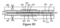
図3Dは、MEA 375が、CCMではなく、触媒層のない電解質膜372を有することを除いて、図3Bのアセンブリと類似した単電池アセンブリを示している。GIG 376は、触媒層373、379が上に設けられたGDL 370を有している。図3Eは、複数の電池380を組み込んだ燃料電池スタックを示している。
FIG. 3D shows a single cell assembly that is similar to the assembly of FIG. 3B, except that the
図4A及び4Bはそれぞれ、一実施形態によるGIG 400の横断面図及び平面図を示している。GIG 400は、ガスケット410と、ガス拡散層(GDL)405とを有している。
4A and 4B show a cross-sectional view and a plan view, respectively, of a
ガスケット410は、GDL 405に対して配置された第1のガスケット層411を有する層構造である。一実施形態において、図4Aに最も良く示されているように、GDL 405は、第1のガスケット層411内の開口部490よりもわずかに小さい。この実施形態において、GDL 405は、第1のガスケット層411の開口部490内に配置されている。先に議論したように、第1のガスケット層411は、ポリイミド、ポリエチレンナフタレート(PEN)、ポリエチレンテレフタレート(PET)、並びに/又は、十分に薄く、十分に強く、燃料電池の環境、すなわち、水、水素、及び/若しくは酸素の存在下での80℃〜100℃の温度に十分に適合する硬質なポリマー材料などの他の類似の材料のような、様々な種類の高分子材料を含んでよい。
The
ガスケット410は、第1のガスケット層411の一方の表面上に設けられた接着剤層412を有し、また所望により、接着剤ライナー413を有する。第1のガスケット層及び接着剤層412の材料は、接着剤層412が第1のガスケット層411に良好に接着するように選択される。接着剤層412は、感圧性接着剤(PSA)又は加熱活性化接着剤を含んでもよい。
The
ガスケット410は、GDL 405と第1のガスケット層411とを互いに接合する第2のガスケット層414を有している。本明細書で議論する様々な実施形態において、第2のガスケット層414は、室温で固体である材料であって、熱及び/又は圧力で加工されてGDL 405と第1のガスケット層411との間の接合部を形成する材料から形成されてよい。熱及び/又は圧力を材料に作用させると、材料は、GDL 405と第1のガスケット層411との間の接合部を形成するように、十分に流動するか又は変形する。第2のガスケット層414を形成するために使用される材料は、本明細書において、加熱/加圧処理可能な材料と呼ばれる。第2のガスケット層の形成に好適な材料には、例えば、加熱処理可能なポリマー又は熱可塑性封止材料が挙げられる。熱可塑性材料は、THV(テトラフルオロエチレンとヘキサフルオロエチレンと二フッ化ビニリデンとのターポリマー)のようなフッ素樹脂、ポリエチレン、エチレンとアクリル酸のコポリマーなどのポリエチレンのコポリマー、サーモ−ボンド(Thermo-Bond)845(スリーエム社(3M)製造の、例えばポリエチレン無水マレイン酸コポリマー)及びサーモ−ボンド668(スリーエム社(3M)製造の、例えばポリエステル)であることができる。また、これらの材料のブレンド、又はこれらにカーボン、ガラス、セラミックなどの充填剤を加えた複合材料が、熱可塑性樹脂として使用されてもよい。溶融温度は、50℃〜180℃、例えば100℃〜150℃となり得る。
The
一実施形態において、第1のガスケット層411及び/又は第2のガスケット層414の表面は、ミクロ構造形状416などの表面形状を有してもよい。いくつかの実施形態において、ミクロ構造形状416は、GIGの封止特性を向上させる。ミクロ構造形状416は、最密な六角形又は他の任意の形状などを含めた多様な形状で形成されてよい。先に議論したように、特定の実施形態において、ミクロ構造形状416の高さは、GIGの封止面が流れ場の頂部と同一平面上にあるか、又は封止面がある程度くぼんでいるセパレータ流れ場プレートに適合するように選択することができる。このくぼんだ変型形態では、ミクロ構造形状416をより高いものにすることができ、プレート厚さの不均一性の存在下で封止の許容度を向上させることができる。場合によっては、第1及び/又は第2のガスケット層411、414の好ましい表面形状416は、封止をなすのに適切な隆起部を有する燃料電池流れ場プレートへの接合を促進するために、実質的に平坦である。
In one embodiment, the surface of the
いくつかの実施形態において、第2のガスケット層414を形成するために使用される加熱/加圧処理可能な材料が、開口部を有するフレームへと切断され、GDL 405の外縁部406(図4B)及び第1のガスケット層411の内縁部417の上に置かれる。置かれた後、熱及び/又は圧力がサブアセンブリに与えられ、加熱/加圧処理可能な材料の一部が、GDL 405の隣接する縁部及び/又は表面に、そして第1のガスケット層411の隣接する縁部及び/又は表面に流れ込む。熱及び/又は圧力を与えると、第2のガスケット層414は第1のガスケット層411とGDL 405の双方に接着し、これにより、第1のガスケット層411がGDL 405に取り付けられる。ホットプレスに使用される圧縮工具の表面は、第1及び/又は第2のガスケット層411、414の表面上にミクロ構造形状を生じさせるために、ミクロ構造形状を(凹凸を逆にして)有してもよい。いくつかの実施形態において、GIG 401のGDL 405は、図4Cに示すように、一方の表面上に設けられた触媒層415を更に有してもよい。
In some embodiments, the heat / pressure processable material used to form the
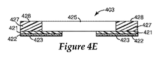
図4D及び4Eは、GIG 402、403の実施形態を示しており、接着剤層422と所望による接着剤ライナー423とを有する第1のガスケット層421が、GDL 425の下に配置されている。図4D及び4Eに示す実施形態において、第2のガスケット層424、427は、GDL 425に隣接する第1のガスケット層421上に設けられている。いくつかの実現形態において、第2のガスケット層424、427の材料は、GDL 425の上面に重なってもよい。第2のガスケット層424、427は、ミクロ構造形状426(図4D)を有しても、実質的に平坦な封止面428(図4E)を有してもよい。
4D and 4E show an embodiment of
いくつかの実施形態において、GIGは、GDLを第1のガスケット層上に配置するのに先立って、第2のガスケット層を形成するために使用される加熱/加圧処理可能なガスケット材料を第1のガスケット層上に置くか又は蒸着させることによって組み立てられる。例えば、加熱/加圧処理可能なガスケット材料は、第1のガスケット層の表面上にスクリーン印刷されるか又は別の方法で蒸着されてよい。次いで、GDLは、第1のガスケット層の上に配置される。いくつかの実現形態において、第2のガスケット層のガスケット材料の一部分は、GDLと第1のガスケット層との間に設けられてもよい。GDLを置いた後、熱及び/又は圧力がサブアセンブリに与えられ、加熱/加圧処理可能な材料の一部が、GDLの隣接する縁部及び/又は表面に、そして第1のガスケット層の隣接する縁部及び/又は表面に流れ込む。 In some embodiments, the GIG may apply the heat / pressure processable gasket material used to form the second gasket layer prior to placing the GDL on the first gasket layer. It is assembled by placing on one gasket layer or by vapor deposition. For example, a heat / pressure processable gasket material may be screen printed or otherwise deposited on the surface of the first gasket layer. The GDL is then placed over the first gasket layer. In some implementations, a portion of the gasket material of the second gasket layer may be provided between the GDL and the first gasket layer. After placing the GDL, heat and / or pressure is applied to the subassembly so that a portion of the heatable / pressurizable material can be applied to the adjacent edge and / or surface of the GDL and to the first gasket layer. Flows into adjacent edges and / or surfaces.
図4Fは、上述のプロセスに従って形成され得るGIG 404を示している。この実現形態において、第2のガスケット層の加熱/加圧処理可能な材料485の一部が、GDL 480と第1のガスケット層481との間に設けられる。第1のガスケット層481は、接着剤層482と所望による接着剤ライナー483とを有している。第2のガスケット層484は、ミクロ構造形状を有してもよく、また、図4Fに示すように実質的に平坦であってもよい。
FIG. 4F shows
図4A〜4Fに示すGIGなどの複数のGIGを備えるウェブが、GIGサブアセンブリウェブとしてロールツーロールプロセスで作製されてもよい。図5Aは、図4A〜4Cに示すGIGと類似した複数のGIG 510を備えるGIGウェブ500の横断面図を示している。GIGサブアセンブリ構成要素の取扱い及び搬送を容易にするために、第2のガスケット層514を形成する加熱/加圧処理可能な材料が、第1のキャリアウェブ531上に設けられてもよく、また、第1のガスケット層が、作製プロセスの間に第2のキャリアウェブ532上に設けられてもよい。
A web comprising a plurality of GIGs such as the GIGs shown in FIGS. 4A-4F may be made in a roll-to-roll process as a GIG subassembly web. FIG. 5A shows a cross-sectional view of a
作製の間、第2のガスケット層514を形成する加熱/加圧処理可能な材料が、第1及び第2のキャリアウェブ531、532の動作によって、一対の接合ローラーなどの圧縮装置において、第1のガスケット材料511及びGDL 505と近づけられる。接合ローラーにおいて、熱及び/又は圧力が、加熱/加圧処理可能な材料に与えられて、材料が流動するか又は変形し、第1のガスケット材料511をGDL 505に接合する第2のガスケット層514が形成される。各GIGは、ミクロ構造形状516を有していても有していなくてもよい。接着剤層512及び所望による接着剤ライナー513が、第1のガスケット層511上に設けられている。図5Bは、第2のキャリアウェブ532を有し図5Aに示す第1のキャリアウェブ531のないGIGサブアセンブリウェブの平面図(正確な縮尺ではない)を示している。
During fabrication, the heatable / pressurizable material that forms the
図4D〜4Eに示すGIGなどの複数のGIGを備えるウェブが、図5Cに示されている。図5Cは、一実施形態による複数のGIG 520を備えるGIGウェブ502の横断面図を示している。GIGサブアセンブリ構成要素の取扱い及び搬送を容易にするために、第2のガスケット層524を形成する加熱/加圧処理可能な材料が、第1のキャリアウェブ531上に設けられてもよく、また、第1のガスケット層が、接合に先立って作製プロセスの間に第2のキャリアウェブ532上に設けられてもよい。
A web comprising a plurality of GIGs, such as the GIG shown in FIGS. 4D-4E, is shown in FIG. 5C. FIG. 5C shows a cross-sectional view of a
作製の間、第2のガスケット層524を形成する加熱/加圧処理可能な材料が、第1及び第2のキャリアウェブ531、532の動作によって、一対の接合ローラーなどの圧縮装置において、第1のガスケット材料521及びGDL 525と近づけられる。接合ローラーにおいて、熱及び/又は圧力が、加熱/加圧処理可能な材料に与えられて、材料が流動するか又は変形し、第1のガスケット材料521をGDL 525に接合する第2のガスケット層524が形成される。接着剤層522及び所望による接着剤ライナー523が、第1のガスケット層521上に設けられている。
During fabrication, the heatable / pressurizable material that forms the
特定の実施形態において、上で説明し図4A〜5Cに示したプロセスに従って作製されたGIG及び/又はGIGサブアセンブリウェブは、後のプロセスにおいてMEA又はMEAサブアセンブリウェブを形成するために使用されてもよい。図6A及び6Bは、触媒被覆電解質膜の第1及び第2の表面上に設けられたGIGを使用して作製されたMEAを示している。図6Aは、触媒被覆電解質膜(CCM)630の第1及び第2の表面上に設けられたGIG 610、620を示している。各GIG 610、620は、第1のガスケット層611、621を有しており、これら第1のガスケット層611、621は、ミクロ構造形状616、626を含んでもよい。接着剤層612、622が、第1のガスケット層611、621の各々の上に設けられている。GIG 610、620の第1のガスケット層611、621の各々は開口部を有しており、GDL 605、606がその開口部内に配置されている。
In certain embodiments, a GIG and / or GIG subassembly web made according to the process described above and shown in FIGS. 4A-5C can be used to form an MEA or MEA subassembly web in a later process. Also good. 6A and 6B show an MEA made using GIG provided on the first and second surfaces of the catalyst coated electrolyte membrane. FIG. 6A shows GIGs 610, 620 provided on the first and second surfaces of a catalyst coated electrolyte membrane (CCM) 630. Each GIG 610, 620 has a
図6Aに示すGDL 605、606は、GDL 605、606が第1のガスケット層611、621の開口部に嵌合するように、第1のガスケット層611、621の開口部よりもわずかに小さいものとなっている。いくつかの実現形態において、GDL 605、606は、GDL 605、606の外縁部617、627が第1のガスケット層611、621の内縁部618、628と重なるように、第1のガスケット層611、621の開口部よりもわずかに大きくてもよい。各GIGは、加熱/加圧処理可能な材料から形成された第2のガスケット層614、624を有している。
The
熱及び/又は圧力を与えられた後、加熱/加圧処理可能な材料は、第1のガスケット層611、621とGDL 605、606とを接合する第2のガスケット層614、624を形成するように流動する。接合プロセスの間、GIG 601の封止性を向上させるために、ミクロ構造形状が、第2のガスケット層614及び/又は第1のガスケット層611に付与されてもよい。
After being applied with heat and / or pressure, the heat / pressurizable material may form a
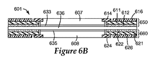
図6Bは、図6BのGIG 650、660がGDL 607、608の表面上に触媒層633、634を有することを除いて、図6Aに示すMEAと類似したMEA 601を示している。この実施形態において、電解質膜636は、触媒層を有していても有していなくてもよい。
FIG. 6B shows an
図6Cは、膜635と触媒層631、632とを有する触媒被覆電解質膜(CCM)630の第1及び第2の表面上に設けられたGIG 680、690を示している。各GIG 680、690は、第1のガスケット層641、651を有している。接着剤層642、652が、第1のガスケット層641、651の各々の上に設けられている。この実施形態において、GDL 603、609は、第1のガスケット層641、651に重なっている。各GIG 680、690は、加熱/加圧処理可能な材料から形成された第2のガスケット層644、654を有している。この実施形態において、第2のガスケット層644、654は、ミクロ構造形状626、656を有している。
FIG. 6C shows
図7は、一実施形態による、ロールツーロール製造プロセスによって作製され得る複数のMEAを備えるMEAサブアセンブリウェブ700の横断面図を示している。MEAサブアセンブリウェブ700は、各GIGサブアセンブリから第2のキャリアウェブが除去された後に、図5Aに示すような2つのGIGサブアセンブリウェブを使用して作製されてもよい。第2のキャリアウェブが除去された後、また使用されている場合は接着ライナーも除去された後、一方のGIGサブアセンブリ701は、第1のガスケット層711の接着剤層712を介してCCM 730の一方の表面に接着剤で接合される。もう一方のGIGサブアセンブリ702は、MEAサブアセンブリウェブ700を形成するように、CCM 730の反対側の表面に接着剤で接合される。このプロセスでは、GIGサブアセンブリウェブ701、702の各々の第1のキャリアウェブ731は元のままに残され、それによって、後の処理工程におけるMEAサブアセンブリウェブ700の取扱いを容易にすることができる。
FIG. 7 illustrates a cross-sectional view of an
ここで図8を参照すると、本発明の実施形態による燃料電池スタック800の単電池アセンブリの横断面図が示されている。燃料電池スタックは、上述のように流体流れプレート860、861の間に挟まれた2つのGIG 851、855を組み込んだ五層MEA 850を備えている。
Referring now to FIG. 8, a cross-sectional view of a unit cell assembly of a
MEAと流れ場プレートとを有する燃料電池の作製は、ロールツーロールプロセスによって達成されてもよい。ロールツーロールプロセスに好適な流れ場セパレータプレートなどの、ロールツーロールによる燃料電池の作製に有用な方法及び装置が、参照によって本願にすべてが組み込まれる同一所有者の米国特許公開第20060141328号に記載されている。 Fabrication of a fuel cell having an MEA and a flow field plate may be accomplished by a roll-to-roll process. A method and apparatus useful for making a roll-to-roll fuel cell, such as a flow field separator plate suitable for a roll-to-roll process, is described in commonly owned U.S. Patent Publication No. 200601141328, which is incorporated herein by reference in its entirety. Has been.
燃料電池800のMEA 850は、アノード触媒層853とカソード触媒層854との間に電解質膜852を有している。いくつかの構成において、アノード触媒層853とカソード触媒層854の一方又は双方が、触媒被覆膜(CCM)を形成する電解質膜852の表面上に設けられてもよい。他の構成において、先に図6Bに示したように、触媒層853、854は、GDL 805、825の表面上に設けられてもよい。更なる他の構成において、触媒層853、854は、一部分は電解質膜852上に、一部分はGDL 805、825上に設けられてもよい。
The
アノード触媒層853及びカソード触媒層854は、本明細書で説明するように構成された電解質膜852とGIG 851、855との間に設けられている。各GIG 851、855は、GDL 805、825と、第1のガスケット層811、821と、接着剤層812、822と、第1のガスケット層811、821をGDL 805、825に接合する第2のガスケット層814、824とを有している。ガスケット付きMEA 850の組み立て前に、GIG 851、855は、MEA 850の組み立ての間に取り外される接着剤ライナーを所望により有している。接着剤ライナーの除去後、GIG 851、855の接着剤層812、822は、CCMの表面に、及び/又は、いくつかの構成においては互いに接着して、ガスケット付きMEA 850を形成する。
The
図8に示す例において、GIG 851、855の第1のガスケット層811、821及び/又は第2のガスケット層814、824は、GIG 851、855と燃料流れプレート860、861との間の封止を促進するために、所望によるミクロ構造形状816、826を有している。流れ場プレート860、861の各々は、水素及び酸素燃料が通過するガス流れチャネル843及びポートの領域を有している。図8に示す構成において、流れ場プレート860、861は、単極の流れ場プレートとして構成されている。他の構成において、流れ場プレート860、861は、多数のMEAを積み重ねて所望の電圧を燃料電池スタック全体にわたって達成するために、二極の流れ場プレートを備えてもよい。
In the example shown in FIG. 8, the
いかなる好適な電解質膜も、本発明の実施において使用されてよい。有効なPEM厚さは、約200μmと約15μmとの間の範囲に及ぶ。テトラフルオロエチレン(TFE)と、式:FSO2−CF2−CF2−O−CF(CF3)−CF2−O−CF=CF2に従うコモノマーとのコポリマーは既知であり、スルホン酸の形態で、すなわち、FSO2−末端基をHSO3−に加水分解して、デラウェア州ウィルミントン(Wilmington)のデュポンケミカル社(DuPont Chemcial Company)によってNAFION(登録商標)の商標名で販売されている。NAFION(登録商標)は、燃料電池に使用するための高分子電解質膜の製作に広く使用されている。また、テトラフルオロエチレン(TFE)と、式:FSO2−CF2−CF2−O−CF=CF2に従うコモノマーとのコポリマーは既知であり、スルホン酸の形態で、すなわち、FSO2−末端基をHSO3−に加水分解して、燃料電池に使用するための高分子電解質膜の製作に使用されている。最も好ましいのは、FSO2−末端基をHSO3−に加水分解した、テトラフルオロエチレン(TFE)とFSO2−CF2CF2CF2CF2−O−CF=CF2とのコポリマーである。PEM構造に好適な他の材料が、参照によって本願に組み込まれる、2005年9月13日出願の同一所有者の米国特許出願第11/225690号に記載されている。 Any suitable electrolyte membrane may be used in the practice of the present invention. Effective PEM thickness ranges between about 200 μm and about 15 μm. Copolymers of tetrafluoroethylene (TFE) and comonomers according to the formula: FSO2-CF2-CF2-O-CF (CF3) -CF2-O-CF = CF2 are known and are in the form of sulfonic acids, i.e. FSO2-. The end group is hydrolyzed to HSO3- and sold under the trade name NAFION® by DuPont Chemcial Company of Wilmington, Delaware. NAFION® is widely used in the production of polymer electrolyte membranes for use in fuel cells. Also, copolymers of tetrafluoroethylene (TFE) and comonomers according to the formula: FSO2-CF2-CF2-O-CF = CF2 are known and are in the form of sulfonic acids, i.e. hydrolyzed FSO2- terminal groups to HSO3-. It is decomposed and used to fabricate polymer electrolyte membranes for use in fuel cells. Most preferred is a copolymer of tetrafluoroethylene (TFE) and FSO2-CF2CF2CF2CF2-O-CF = CF2, wherein the FSO2-terminal group is hydrolyzed to HSO3-. Other materials suitable for PEM structures are described in commonly owned US patent application Ser. No. 11 / 25,690 filed on Sep. 13, 2005, which is incorporated herein by reference.
いくつかの実施形態において、触媒層は、塩化白金酸の還元などの湿式化学法によってより大きな炭素粒子にコーティングされたPt又はPt合金を含んでもよい。この形態の触媒は、アイオノマー結合剤、溶媒、また多くの場合、ポリテトラフルオロエチレン(PTFE)粒子と共に分散されて、膜又はGDLのいずれかに塗布されるインク、ペースト、又はディスパージョンを形成する。 In some embodiments, the catalyst layer may comprise Pt or a Pt alloy coated on larger carbon particles by a wet chemical method such as reduction of chloroplatinic acid. This form of catalyst is dispersed with an ionomer binder, solvent, and often polytetrafluoroethylene (PTFE) particles, to form an ink, paste, or dispersion that is applied to either the membrane or GDL. .
いくつかの実施形態において、触媒層は、触媒材料の粒子又はナノ構造薄膜(NSTF)を支えるナノ構造支持要素を備えてもよい。ナノ構造触媒層は、支持体としての炭素粒子を含有しておらず、したがって、触媒粒子の高密度分布を形成する電解質膜の極薄表面層の中に組み込まれてもよい。NSTF触媒層を使用することで、触媒利用率を、分散法によって形成された触媒層と比べて非常に高くすることができ、また、炭素支持体が存在しないことで、高電圧及び高温での浸食に対する更なる耐性がもたらされる。いくつかの実現形態において、CCMの触媒表面積は、ミクロ構造形状を電解質膜の上にエンボス加工することによって、更に拡張されてもよい。NSTF触媒は、ミクロ構造触媒転写基材の上にコーティングされ、このミクロ構造触媒転写基材は、加熱及び加圧下で触媒を電解質膜に積層転写すると、電解質膜の表面をミクロ複製させる(micro-replicated)。ミクロ構造触媒転写基材に関する方法及びシステムが、参照によって本願に組み込まれる同一所有者の米国特許第6,136,412号に記載されている。ミクロ構造電解質膜及びNSTF触媒層を製作するための様々な方法が、参照によって本願に組み込まれる同一所有者の特許文書:米国特許第4,812,352号及び同第5,879,827号、2005年9月13日出願の米国特許出願番号第11/225,690号、並びに、2005年9月13日出願の米国特許出願番号第11/224,879号に記載されている。 In some embodiments, the catalyst layer may comprise nanostructured support elements that support particles of catalyst material or nanostructured thin films (NSTF). The nanostructured catalyst layer does not contain carbon particles as a support and may therefore be incorporated into the ultrathin surface layer of the electrolyte membrane that forms a dense distribution of catalyst particles. By using the NSTF catalyst layer, the catalyst utilization rate can be made very high compared to the catalyst layer formed by the dispersion method, and the absence of the carbon support allows for high voltage and high temperature. Additional resistance to erosion is provided. In some implementations, the catalytic surface area of the CCM may be further expanded by embossing the microstructure shape onto the electrolyte membrane. The NSTF catalyst is coated on a microstructure catalyst transfer substrate, and when the catalyst is laminated and transferred to the electrolyte membrane under heat and pressure, the surface of the electrolyte membrane is micro-replicated (micro- replicated). Methods and systems relating to microstructured catalyst transfer substrates are described in commonly owned US Pat. No. 6,136,412, incorporated herein by reference. Various methods for fabricating microstructured electrolyte membranes and NSTF catalyst layers are described in commonly owned patent documents: US Pat. Nos. 4,812,352 and 5,879,827, incorporated herein by reference. U.S. Patent Application No. 11 / 225,690 filed on September 13, 2005, and U.S. Patent Application No. 11 / 224,879 filed on September 13, 2005.
NSTF触媒層は、針状のナノ構造支持体の上に触媒材料を真空蒸着させることによって形成され得る、細長いナノスケール粒子を含んでいる。本発明における使用に好適なナノ構造支持体は、C.I.ピグメントレッド(C.I. PIGMENT RED)149(ペリレン赤)などの有機顔料のウィスカを含んでもよい。結晶性ウィスカは、実質的に均一であるが同一ではない横断面、及び長さと幅との大きな比を有する。ナノ構造支持体ウィスカは、触媒作用に好適なコーティング材料でコーティングされ、それによって、複数の触媒部位として作用することが可能な、微細なナノスケールの表面構造がウィスカに加えられる。 The NSTF catalyst layer includes elongated nanoscale particles that can be formed by vacuum deposition of the catalyst material on a needle-like nanostructure support. Nanostructured supports suitable for use in the present invention include C.I. I. An organic pigment whisker such as C.I. PIGMENT RED 149 (perylene red) may be included. Crystalline whiskers have a substantially uniform but not identical cross-section and a large ratio of length to width. The nanostructured support whisker is coated with a coating material suitable for catalysis, thereby adding to the whisker a fine nanoscale surface structure that can act as a plurality of catalytic sites.
特定の実現形態において、ナノ構造支持要素は、継続的な螺旋転位の成長によって拡張されてもよい。ナノ構造支持要素の長さの延長及び密度の増加によって、触媒作用のための表面積を増加させることができる。ナノ構造支持要素の長さを延長するためのプロセスが、先に組み込まれた米国特許出願第11/225,690号に記載されている。それに加えて又はそれに代わって、ナノ構造支持要素の複数の層がまた、表面積の増加をもたらす。ナノ構造支持要素の複数の層を製造するためのプロセスが、先に組み込まれた米国特許出願第11/224,879号に記載されている。そのナノ構造支持体要素は、触媒材料でコーティングされてナノ構造薄膜触媒層を形成する。一実現形態によれば、触媒材料は、白金族金属などの金属を含む。一実施形態において、触媒被覆ナノ構造支持要素は、触媒被覆膜を形成するために、電解質膜の表面に転写されてもよい。別の実施形態において、触媒被覆ナノ構造支持要素は、GDL表面上に形成されてもよい。 In certain implementations, the nanostructured support elements may be expanded by continuous screw dislocation growth. By extending the length and increasing the density of the nanostructured support element, the surface area for catalysis can be increased. A process for extending the length of a nanostructured support element is described in previously incorporated US patent application Ser. No. 11 / 225,690. In addition or alternatively, multiple layers of nanostructured support elements also provide an increase in surface area. A process for producing multiple layers of nanostructured support elements is described in previously incorporated US patent application Ser. No. 11 / 224,879. The nanostructured support element is coated with a catalyst material to form a nanostructured thin film catalyst layer. According to one implementation, the catalyst material comprises a metal, such as a platinum group metal. In one embodiment, the catalyst coated nanostructure support element may be transferred to the surface of the electrolyte membrane to form a catalyst coated membrane. In another embodiment, the catalyst coated nanostructure support element may be formed on a GDL surface.
GDLは、反応ガスを通過させる一方で電極から電流を集めることが可能な任意の材料、典型的には織布又は不織布の炭素繊維紙又は炭素繊維布であることができる。GDLは、ガス状の反応物質及び水蒸気を触媒及び膜へと多孔性によって出入りさせ、また、外部負荷に電力供給するために、触媒層内で生成された電子電流を集める。 The GDL can be any material, typically a woven or non-woven carbon fiber paper or carbon fiber cloth, that allows reactant gas to pass through while collecting current from the electrodes. GDL collects the electron current generated in the catalyst layer to allow gaseous reactants and water vapor to enter and exit the catalyst and membrane through porosity and to power external loads.
GDLは、炭素繊維構造体(例えば、織布及び不織布カーボン繊維構造体)など、任意の好適な導電性多孔性基材であってよい。市販されている炭素繊維組織の例には、マサチューセッツ州ローウェル(Lowell)のバラードマテリアルプロダクツ社(Ballard Material Products)による商標表記「AvCarb P50」の炭素繊維紙、マサチューセッツ州ウォバーン(Woburn)のエレクトロケム社(ElectroChem, Inc.)から入手できる「Toray」炭素紙、マサチューセッツ州ローレンス(Lawrence)のスペクトラコープ社(Spectracorp)による「SpectraCarb」炭素紙、マサチューセッツ州イーストウォルポール(East Walpole)のホリングスワース&ヴォース社(Hollingsworth & Vose Company)による「AFN」不織布炭素布、ミズーリ州セントルイス(St. Louis)のゾルテック社( Zoltek Companies, Inc.)による「Zoltek」炭素布、及び、日本国東京都の三菱レイヨン社(Mitsubishi Rayon Co.)による「U−105」炭素布が挙げられる。また、GDLは、疎水性を増すように又は付与するように処理されてもよい。例えば、GDLは、ポリテトラフルオロエチレン(PTFE)及びフッ素化エチレンプロピレン(FEP)など、高度にフッ素化されたポリマーで処理されてもよい。 The GDL may be any suitable conductive porous substrate, such as carbon fiber structures (eg, woven and non-woven carbon fiber structures). Examples of commercially available carbon fiber structures include carbon fiber paper under the trademark designation “AvCarb P50” by Ballard Material Products, Inc., Lowell, Massachusetts, Electrochem, Inc., Woburn, Massachusetts. “Toray” carbon paper available from (ElectroChem, Inc.), “SpectraCarb” carbon paper by Spectracorp of Lawrence, Massachusetts, Hollingsworth & Vose, East Walpole, Massachusetts "AFN" non-woven carbon cloth by Hollingsworth & Vose Company, "Zoltek" carbon cloth by Zoltek Companies, Inc., St. Louis, Missouri, and Mitsubishi Rayon Co., Tokyo, Japan (Mitsubishi Rayon Co And "U-105" carbon cloth. The GDL may also be treated to increase or impart hydrophobicity. For example, GDL may be treated with highly fluorinated polymers such as polytetrafluoroethylene (PTFE) and fluorinated ethylene propylene (FEP).
図9Aは、本発明の実施形態によるGIGを製作するためのプロセスを示している。このプロセスは、個々のGIGに対して、又はロール品として形成された複数のGIGに対して実施されてよい。加熱/加圧処理可能な材料が、接着剤層と所望による接着剤ライナーとを有する第1のガスケット層上に置かれるか又は蒸着される(902)。例えば、加熱/加圧処理可能な材料は、1つ以上の開口部が第1のガスケット層の中に切断される前又は切断された後に、第1のガスケット層の表面上に、シルクスクリーン印刷されるか又は他の方法で蒸着されてもよい。加熱/加圧処理可能な材料の蒸着は、加熱/加圧処理可能な材料が第1のガスケット層の表面全体にわたって傾斜する厚さを有するように実施されてもよい。GDLは、GDLが第1のガスケット層の開口部の縁部に重なると共に加熱/加圧処理可能な材料が第1のガスケット層とGDLとの間に設けられるように、第1のガスケット層に対して配置される(904)。GDLの下方の加熱/加圧処理可能な材料の厚さは、例えば、第1のガスケット層上の他の場所における加熱/加圧処理可能な材料の厚さよりも薄いものであってもよい。GDLと、第1のガスケット層と、加熱/加圧処理可能な材料とを有するサブアセンブリは、接合ステーションにおいて成形される(906)。加熱/加圧処理可能な材料は、第1のガスケット層をGDLに接合する第2のガスケット層を形成するように、変形するか又は流動する。 FIG. 9A illustrates a process for fabricating a GIG according to an embodiment of the present invention. This process may be performed for individual GIGs or for multiple GIGs formed as rolls. A heat / pressure processable material is placed on or deposited on a first gasket layer having an adhesive layer and an optional adhesive liner (902). For example, the heat / pressure processable material may be silkscreen printed on the surface of the first gasket layer before or after one or more openings are cut into the first gasket layer. Or may be otherwise deposited. The deposition of the heat / pressure processable material may be performed such that the heat / pressure processable material has a thickness that is inclined over the entire surface of the first gasket layer. The GDL is formed on the first gasket layer such that the GDL overlaps the edge of the opening of the first gasket layer and a heatable / pressurizable material is provided between the first gasket layer and the GDL. (904). The thickness of the heatable / pressurizable material below the GDL may be, for example, thinner than the thickness of the heatable / pressureable material elsewhere on the first gasket layer. A subassembly having a GDL, a first gasket layer, and a heat / pressure processable material is molded at a bonding station (906). The heatable / pressurizable material deforms or flows to form a second gasket layer that joins the first gasket layer to the GDL.
図9Bは、別の実施形態によるGIGを製作するためのプロセスを示す流れ図である。GDLが、第1のガスケット層の縁部に対して配置される(910)。例えば、GDLは、第1のガスケット層内に開口部を形作る、第1のガスケット層の内縁部に対して配置されてもよい。第1のガスケット層は、接着剤層を一方の表面上に、また所望により接着剤ライナーを有する。熱及び/又は圧力によって流動するか又は変形するガスケット材料が、第1のガスケット層の、接着剤層及び/又は金型板から反対側の表面上に置かれる(920)。GDL、第1のガスケット層、及びガスケット材料が、金型内に置かれ成形される(930)。この成形プロセスにより、ガスケット材料から第2のガスケット層が形成され、GDLと第1のガスケット層とが接合される。いくつかの構成において、ガスケット材料は、GDL及び第1のガスケット層の隣接する縁部の上にかぶさるようにダイカットされた加熱/加圧処理可能なポリマーを備える。いくつかの構成において、ミクロ構造形状が、成形プロセスの間に、第2のガスケット層及び/又は第1のガスケット層の表面上にエンボス加工される。 FIG. 9B is a flow diagram illustrating a process for fabricating a GIG according to another embodiment. A GDL is placed (910) against the edge of the first gasket layer. For example, the GDL may be placed against the inner edge of the first gasket layer that forms an opening in the first gasket layer. The first gasket layer has an adhesive layer on one surface and optionally an adhesive liner. A gasket material that flows or deforms due to heat and / or pressure is placed 920 on the surface of the first gasket layer opposite the adhesive layer and / or mold plate. The GDL, first gasket layer, and gasket material are placed in a mold and molded (930). This molding process forms a second gasket layer from the gasket material and bonds the GDL and the first gasket layer. In some configurations, the gasket material comprises a heat / pressure processable polymer die cut over the adjacent edges of the GDL and the first gasket layer. In some configurations, the microstructure shape is embossed on the surface of the second gasket layer and / or the first gasket layer during the molding process.
ここで図10A〜10Gに目を向けると、本発明の実施形態による、GIGが構成材料の層から構成される様々な処理段階を表す多数の図が示されている。図10Aの横断面図に示すように、第1のガスケット層1011は、GDLの寸法よりわずかに大きい開口部1060を有するようにダイカットされている。第1のガスケット層1011は、PEN、PET、ポリイミド、又は他の好適なポリマーを含んでよい。第1のガスケット層1011は、接着剤層1012と所望による接着剤ライナー1013とを有している。例えば、一実現形態において、第1のガスケット層は約0.125mmの厚さを有してもよく、接着剤層は約0.0125mm未満の厚さを有してもよく、また接着剤ライナーは、約0.025mmの厚さを有してもよい。
Turning now to FIGS. 10A-10G, there are shown a number of diagrams representing various processing stages in which a GIG is composed of layers of constituent materials, according to embodiments of the present invention. As shown in the cross-sectional view of FIG. 10A, the
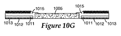
ダイカットされた第1のガスケット層/接着剤層/接着剤ライナー1011〜1013は、GDL及び第2のガスケット層の材料、例えばシリコーンが接着することのない剥離コーティング又はライナーを有するフラットプレート1090の上に、接着剤ライナー1013側を下にして置かれている(図10B)。GDL 1005が、図10Cに示すように、第1のガスケット層の開口部の中に取り付けられる。ある構成において、シリコーンなど、流動可能で硬化可能なガスケット材料のビード1018が、第1のガスケット層1011の自由表面上に置かれる(図10D)。金型板1095が、上記のサブアセンブリの上部に取り付けられる(図10E)。金型板1095は、流動可能なガスケット材料の物質が接着するのを防止する剥離コーティングを有している。金型板1095は、第1のガスケット層1011の領域に対応するミクロ構造パターン表面1096を組み込んでもよい。金型板1095は、GDL 1005の高さの何分の1かに対応するように、特定の深さ、例えば約0mm〜約0.250mmの溝を有していてもよい。
Die-cut first gasket layer / adhesive layer / adhesive liners 1011-1013 are on top of a
上記のサブアセンブリは、プレス機の中に導入され、例えば約60℃〜約150℃で約25トン〜約30トンの加熱及び加圧下で、約2分間〜約10分間にわたって成形されて(図10F)、シリコーンを流動させ、GIGを所望の厚さに到達させることができる。そのシリコーンは硬化されて、第2のガスケット層1015を形成する。図10Gは、プレス機1060から取り出された後のGIGを示している。説明した工程は、任意の好適な順序で実施されてよい。
The subassembly is introduced into a press and molded, for example, at about 60 ° C. to about 150 ° C. for about 2 minutes to about 10 minutes under heating and pressure of about 25 tons to about 30 tons (FIG. 10F), allowing the silicone to flow and the GIG to reach the desired thickness. The silicone is cured to form a
図11A〜11Hは、本発明の実施形態によるGIGを組み込んだMEAを製作するためのプロセスを示す多数の略図を示している。図11Aは、真空テーブル1190上に置かれた第1のGIG 1180を示しており、この真空テーブル1190は、多層MEAの様々な層の位置決めを促進するように構成された位置合わせピン1191を有している。第1のGIG11 80の微孔性層は、上向きに面している。真空にされて、第1のGIG 1180が定位置に保持される。接着剤ライナー1113は、図11Bに示すように、第1のGIG 1180から取り外される。
11A-11H show a number of schematic diagrams illustrating a process for fabricating a MEA incorporating a GIG according to an embodiment of the present invention. FIG. 11A shows a
図11Cは、真空プレート1193の上に置かれたCCM 1185を示しており、この真空プレート1193は、真空テーブル1190のピン1191と係合するための適切な位置合わせ形状1194を有している。真空プレート1193が真空にされて、CCM 1185が定位置に保持される。図11Dに示すように、CCM 1185を保持する真空プレート1193は、第1のGIG 1180とCCM 1185の層が正確に組み合わされるようにピン1191と形状1194とを位置合わせして、真空テーブル1190/第1のGIG 1180の上部に置かれる。真空プレート1193が真空を解除され、真空プレート1193が取り外されて、CCM 1185は第1のGIG 1180に接着剤によって貼り付けられたままとなる。
FIG. 11C shows the
図11Eに示すように、第2のGIG 1181が、微孔性層側を上にして、真空プレート1193内に置かれる。真空にされて、第2のGIG 1181が定位置に保持される。接着剤ライナー1114は、第2のGIG 1181から取り外される。図11Gに示すように、真空プレート1193/第2のGIG 1181は、真空テーブル1190上のCCM 1185/第1のGIG 1180アセンブリの上部に置かれる。図11Hに示すように、真空プレート1193が真空を解除され、プレート1193が取り外されて、第2のGIG 1181/CCM 1185/第1のGIG 1180MEAアセンブリが残される。MEAは、真空テーブル1190から取り外され、また、その部品の外のり寸法を調整するためにダイカットされてもよい。
As shown in FIG. 11E, a
いくつかの実施形態において、本明細書で説明する実施形態に従って構成されたGIGは、代理人整理番号第62591US002で識別される、同一所有者の米国特許出願に記載されている連続プロセス及び/又はロールツーロールプロセスを通じて製作されてもよく、その米国特許出願は、本願と同時に出願され、引用によって本願に組み込まれる。 In some embodiments, a GIG configured according to embodiments described herein is a continuous process and / or described in a co-owned US patent application identified by attorney docket number 62591 US002. It may be made through a roll-to-roll process, the US patent application being filed concurrently with this application and incorporated herein by reference.
本明細書に提示した実施形態に従って構成されたGIGは、従来のガスケット法に勝る多数の利点をもたらす。従来のプロセスでは、ガスケットの形成に、あるいは、燃料電池構成要素の接合(例えば、CCMへのGDLの接合、又は電解質膜への触媒被覆GDLの接合)に必要な望ましい温度及び圧力を超える温度及び圧力に、MEA及びGDLをさらすことが必要である。製造プロセスの間に高温及び高圧にさらされることは、CCMを通じたGDLの電気短絡の原因となることがある。本明細書において説明するGIGは、CCMによって許容される温度を上回る温度を用いて製造されてもよい。本発明のGIGを使用すると、CCMはこれらの過大温度にさらされることがなく、したがって、緩慢なガスケット製作手順において、場合によってはサイクル時間を短縮することが可能となる。硬化手順の速度は、使用される特定の材料に依存する。加えて、シリコーンなどのガスケット材料が硬化すると、CCMに有害な化学種が放たれることがある。本明細書で説明するGIGを使用すると、CCMがガスケット硬化プロセスにさらされることがない。 A GIG constructed in accordance with the embodiments presented herein provides numerous advantages over conventional gasket methods. In conventional processes, temperatures above and beyond the desired temperature and pressure required for gasket formation or for joining fuel cell components (e.g. joining GDL to CCM or joining catalyst coated GDL to electrolyte membrane) and It is necessary to expose MEA and GDL to pressure. Exposure to high temperatures and high pressures during the manufacturing process can cause electrical shorts in the GDL through the CCM. The GIG described herein may be manufactured using temperatures above those allowed by the CCM. Using the GIG of the present invention, the CCM is not exposed to these over-temperatures, thus allowing cycle times to be reduced in some slow gasket fabrication procedures. The speed of the curing procedure depends on the specific material used. In addition, when a gasket material such as silicone is cured, chemical species that are detrimental to CCM may be released. Using the GIG described herein, the CCM is not exposed to the gasket curing process.
本明細書で説明するGIGは、製造プロセスの間のCCMのスクラップ化を最小にするために使用されてもよい。まずGIGを形成し、次いでそれらをCCMに貼り付けることは、ガスケット製作プロセスでいかなる失敗が生じても、より高価なCCMの浪費にはつながらないことを意味する。 The GIG described herein may be used to minimize CCM scraping during the manufacturing process. Forming GIGs first and then affixing them to the CCM means that any failure in the gasket fabrication process will not lead to the waste of the more expensive CCM.
従来のガスケット法は、ガスケット層、例えばPEN、PET、又は他のポリマーが、CCMに良好に接合することを必要とする。接合が不十分であると、MEAを動作条件下に置いたときに漏れを生じる結果となる。また、接合が不十分であると、ガスケットが接着できず電解質膜から外れた場合に、製造及びスタックの組み立てプロセスの間にサブアセンブリを取り扱うことが困難となる。本明細書において説明しているガスケット法は、GIG/CCM境界面における接合を増強するものであり、ナノ構造薄膜触媒層が用いられるとき特に有利となるものである。 Conventional gasket methods require a gasket layer, such as PEN, PET, or other polymer, to be well bonded to the CCM. Insufficient bonding results in leakage when the MEA is placed under operating conditions. Insufficient bonding also makes it difficult to handle the subassembly during the manufacturing and stack assembly process if the gasket cannot be bonded and is detached from the electrolyte membrane. The gasket method described herein enhances bonding at the GIG / CCM interface and is particularly advantageous when nanostructured thin film catalyst layers are used.
加えて、一部の従来のガスケット法は、封止面積を適切にし、ガスケットとCCMとの接合面積を十分にするために、ガスケット付きCCMを部品の最終的な外のり寸法と同じ寸法に切断することを必要とする。本発明の手法では、CCMをGDLよりもわずかに大きく、一方の電極からその領域内のもう一方の電極へ反応物質がクロスオーバーするのを防止するのに十分な大きさで切断することが可能となる。本明細書で説明する手法では、好都合にも、必要となる高価な触媒被覆膜の量が減じられる。 In addition, some conventional gasket methods cut the gasketed CCM to the same dimensions as the final outer dimension of the part in order to ensure a good sealing area and a sufficient gasket and CCM bonding area. You need to do. With the technique of the present invention, the CCM is slightly larger than the GDL and can be cut to a size large enough to prevent reactants from crossing over from one electrode to the other in the region. It becomes. The approach described herein advantageously reduces the amount of expensive catalyst coating required.
接合されたGDLを有していないMEAを燃料電池スタックの中に組み込むための従来の手法は、要求される位置合わせ許容誤差が厳しいがために困難を呈する。本明細書で説明する手法は、GDLの接合が不可能であるか又は望ましくないMEAの組み立てをより容易にする。 Conventional approaches for incorporating MEAs that do not have bonded GDLs into a fuel cell stack present difficulties because of the tight alignment tolerances required. The approach described herein makes it easier to assemble MEAs where GDL bonding is not possible or undesirable.
図12〜15は、本明細書で説明する燃料電池アセンブリを組み込み、燃料電池スタックを発電用に使用することができる様々な燃料電池システムを示している。図12に示す燃料電池システム1200は、本明細書で実施形態によって説明したような燃料電池アセンブリが利用され得るシステムについて考えられるもののうちの1つを示している。
FIGS. 12-15 illustrate various fuel cell systems that incorporate the fuel cell assemblies described herein and that can use the fuel cell stack for power generation. The
燃料電池システム1200は、燃料プロセッサ1204と、電力セクション1206と、電力コンディショナ1208とを有している。燃料プロセッサ1204は、燃料改質器を有するものであり、天然ガスなどの原燃料1201を受容し、その原燃料1201を処理して、水素リッチ燃料1202を発生させる。水素リッチ燃料1202は、電力セクション1206に供給される。電力セクション1206内で、水素リッチ燃料1202は、電力セクション1206内に収容された燃料電池スタックのMEAのスタックの中に導入される。また、空気1203が、電力セクション1206に供給され、それによって、燃料電池のスタックのための酸素源が与えられる。
The
電力セクション1206の燃料電池スタックは、直流電力1210と、熱1212と、清浄水1213とを発生させる。高分子電解質膜燃料電池システムは、生成水1213を燃料プロセッサ1204に再供給してもよく、この燃料プロセッサ1204は、水素の大部分を水から、残りを膜又は他の燃料1201から作る。電力セクション1206によって産出された直流電力1210は、電力コンディショナ1208に送られ、この電力コンディショナ1208は、後の利用のために直流電力1210を交流電力1211に変換する。交流電力変換が、直流出力電力を提供するシステムに含められる必要がないことは理解されよう。
The fuel cell stack in the
図13は、燃料供給ユニット1305と、燃料電池電力セクション1306と、電力コンディショナ1308とを有する燃料電池電力供給部1300を示している。燃料供給ユニット1305は、燃料電池電力セクション1306に供給される水素燃料を含んだリザーバを有している。電力セクション1306内で、水素燃料は、電力セクション1306内に収容された燃料電池スタックのMEAの中に、空気又は酸素と共に導入される。
FIG. 13 shows a fuel
燃料電池電力供給システム1300の電力セクション1306は、直流電力と、使用可能な熱と、清浄水とを発生させる。電力セクション1306によって産出された直流電力は、所望により交流電力に変換するために、電力コンディショナ1308に送られてもよい。図13に示す燃料電池電力供給システム1300は、例えば、据置き式又は可搬式の交流又は直流電力発生器として実現されてよい。
The
図14に示す実現形態において、燃料電池システム1400は、燃料電池電力供給部によって産出された電力を使用して、コンピュータを動作させるための電力を供給する。図8と関連して説明したように、燃料電池電力供給システムは、燃料供給ユニット1405と、燃料電池電力セクション1406とを有している。燃料供給ユニット1405は、燃料電池電力セクション1406に水素燃料を供給する。電力セクション1406の燃料電池スタックは、デスクトップ又はラップトップコンピュータなどの、コンピュータ1410を動作させるために使用される電力を発生させる。
In the implementation shown in FIG. 14, the
別の実現形態において、図15に示すように、燃料電池システム1500は、燃料電池電力供給部からの電力を使用して自動車を動作させる。この構成において、燃料供給ユニット1505は、燃料電池電力セクション1506に水素燃料を供給する。電力セクション1506の燃料電池スタックは、自動車1510の駆動機構に連結されたモーター1508を動作させるために使用される電力を発生させる。
In another implementation, as shown in FIG. 15, the
本発明の様々な実施形態の上述の説明は、例示及び説明を目的として提示されたものである。網羅的なものにすること、又は、本発明を、開示した厳密な形に限定することは意図されていない。以上の教示を考慮すれば、多数の修正及び変形が可能である。本発明の範囲は、この詳細な説明によってではなく、むしろ本明細書に添付された特許請求の範囲によって限定されことが意図されている。本発明の実施態様の一部を以下の項目1〜37に記載する。
[1]
ガス拡散層(GDL)と、
前記GDLに接合されたガスケットであって、
第1のガスケット層、
前記第1のガスケット層及び前記GDLと接触するガスケット材料を含む第2のガスケット層であって、前記ガスケット材料が、前記第1のガスケット層に前記GDLを接合する第2のガスケット層、及び
前記第1のガスケット層の表面上に設けられた接着剤層
を備えるガスケットと
を備える、燃料電池の膜電極アセンブリ(MEA)用のサブアセンブリ。
[2]
前記第2のガスケット層の前記ガスケット材料が、前記GDLに侵入する、項目1に記載のサブアセンブリ。
[3]
前記第2のガスケット層が、前記GDLの表面の一部分の上に設けられる、項目1に記載のサブアセンブリ。
[4]
前記第2のガスケット層が、前記第1のガスケット層の反対側の表面上にミクロ構造形状を有する、項目1に記載のサブアセンブリ。
[5]
前記第1のガスケット層がポリマーを含む、項目1に記載のサブアセンブリ。
[6]
前記第1のガスケット層が、PEN、PET、又はポリイミドを含む、項目1に記載のサブアセンブリ。
[7]
前記ガスケット材料が、シリコーン、ゴム、又はフルオロポリマーを含む、項目1に記載のサブアセンブリ。
[8]
前記ガスケット材料が、熱と圧力の少なくとも一方の作用下で流動可能又は変形可能である材料を含む、項目1に記載のサブアセンブリ。
[9]
前記GDLが、前記第1のガスケット層の開口部内に設けられる、項目1に記載のサブアセンブリ。
[10]
前記GDLが、前記第1のガスケット層に重なる、項目1に記載のサブアセンブリ。
[11]
前記接着剤層が、取り外し可能な接着剤ライナーを有する、項目1に記載のサブアセンブリ。
[12]
複数の類似したサブアセンブリを備えるロール品の構成要素である、項目1に記載のサブアセンブリ。
[13]
第1及び第2のサブアセンブリであって、各々が、
ガス拡散層(GDL)と、
前記GDLに接合されたガスケットであって、
第1のガスケット層、
前記第1のガスケット層及び前記GDLと接触するガスケット材料を含む第2のガスケット層であって、前記ガスケット材料が、前記GDLに前記第1のガスケット層を接合する第2のガスケット層、及び
前記第1のガスケット層の反対側の表面上に設けられた接着剤層
を備えるガスケットと
を備える第1及び第2のサブアセンブリと、
前記第1のサブアセンブリと第2のサブアセンブリとの間に配置された電解質膜と、
前記第1のサブアセンブリと前記膜との間の第1の触媒層と、
前記第2のサブアセンブリと前記膜との間の第2の触媒層と
を備える、膜電極アセンブリ(MEA)。
[14]
前記第1及び第2の触媒層が、針状のナノ構造支持体上に形成された触媒材料のナノスケール粒子を有するナノ構造薄膜触媒層を含む、項目13に記載のMEA。
[15]
前記膜、前記第1の触媒層、及び前記第2の触媒層が、触媒被覆膜を形成する、項目13に記載のMEA。
[16]
前記第2のガスケット層の前記ガスケット材料が、前記GDLに侵入する、項目13に記載のMEA。
[17]
前記第2のガスケット層が、前記GDLの表面の一部分の上に設けられる、項目13に記載のMEA。
[18]
前記第1のガスケット層と前記第2のガスケット層の少なくとも一方が、ミクロ構造形状を有する、項目13に記載のMEA。
[19]
前記第1のガスケット層と前記第2のガスケット層の少なくとも一方が、実質的に平坦である、項目13に記載のMEA。
[20]
複数のMEAを備えるロール品の構成要素である、項目13に記載のMEA。
[21]
第1及び第2のサブアセンブリを備える膜電極アセンブリであって、第1及び第2のサブアセンブリの各々が、
ガス拡散層(GDL)と、
前記GDLに接合されたガスケットであって、
第1のガスケット層、
前記第1のガスケット層及び前記GDLと接触するガスケット材料を含む第2のガスケット層であって、前記ガスケット材料が、前記GDLに前記第1のガスケット層を接合する第2のガスケット層、及び
前記第1のガスケット層の反対側の表面上に設けられた接着剤層
を備えるガスケットと、
前記第1のサブアセンブリと第2のサブアセンブリとの間の触媒被覆膜と
を備える、膜電極アセンブリと、
各々が流路の配列を有する第1及び第2の流れ場プレートであって、圧縮力下で前記第1及び前記第2のサブアセンブリの前記ガスケットと接触する第1及び第2の流れ場プレートと
を備える燃料電池スタック。
[22]
前記触媒被覆膜が、ナノ構造薄膜触媒層を備える、項目21に記載の燃料電池スタック。
[23]
前記第2のガスケット層の前記ガスケット材料が、前記GDLに侵入する、項目21に記載の燃料電池スタック。
[24]
前記第2のガスケット層が、前記GDLの表面の一部分の上に設けられる、項目21に記載の燃料電池スタック。
[25]
前記ガスケット層のうちの少なくとも1つが、エンボス加工されたミクロ構造形状を有する、項目21に記載の燃料電池スタック。
[26]
膜電極アセンブリ用のサブアセンブリを製作する方法であって、
サブアセンブリ構成要素を用意する工程であって、
接着剤層を上に設けた第1のガスケット層に対してガス拡散層(GDL)を配置することと、
前記第1のガスケット層上にガスケット材料を置くことと
を含む工程と、
前記サブアセンブリ構成要素を成形して、前記第1のガスケット層と前記GDLとの間の接合部をなす工程であって、前記接合部が、前記ガスケット材料によって形成される工程と
を含む方法。
[27]
前記サブアセンブリ構成要素を用意する工程が、前記第1のガスケット層内に開口部を切断することを更に含み、
前記第1のガスケット層に対して前記GDLを配置することが、前記GDLを前記開口部内に配置することを含む、項目26に記載の方法。
[28]
前記ガスケット材料を硬化させる工程を更に含む、項目26に記載の方法。
[29]
前記サブアセンブリ構成要素を成形する工程が、ミクロ構造形状を有する第2のガスケット層を前記ガスケット材料から形成することを含む、項目26に記載の方法。
[30]
前記サブアセンブリ構成要素を成形する工程が、エンボス加工された形状を有する第2のガスケット層を前記ガスケット材料から形成することを含む、項目26に記載の方法。
[31]
前記サブアセンブリ構成要素を成形する工程が、前記サブアセンブリ構成要素の所定の厚さを達成するように前記サブアセンブリ構成要素を成形することを含む、項目26に記載の方法。
[32]
前記サブアセンブリ構成要素を成形する工程が、ミクロ構造パターンを有する金型板を使用して前記サブアセンブリ構成要素を成形することを含む、項目26に記載の方法。
[33]
前記接着剤層が、取り外し可能なライナーを有する感圧性接着剤層を含む、項目26に記載の方法。
[34]
膜電極アセンブリを製作する方法であって、
第1及び第2のガスケット付きガス拡散層(GDL)サブアセンブリを形成する工程であって、各サブアセンブリの形成が、
接着剤層を上に有する少なくとも第1のガスケット層を備えるガスケット内に開口部を切断することと、
前記開口部の上にガス拡散層を配置することと、
前記第1のガスケット層上にガスケット材料を置くことと、
前記第1のガスケット層、GDL、及び前記流動可能なガスケット材料を成形して、前記第1のガスケット層と前記GDLとの間の接合部をなすことであって、前記接合部が前記ガスケット材料によって形成されることと
を含む工程と、
前記第1のガスケット付きGDLサブアセンブリと第2のガスケット付きGDLサブアセンブリとの間に触媒被覆電解質膜を配置する工程と
を含む方法。
[35]
前記触媒被覆膜を配置する工程が、
前記第1のガスケット付きGDLサブアセンブリ上に前記触媒被覆膜を置くことと、
前記触媒被覆膜及び前記第1のガスケット付きGDLサブアセンブリ上に前記第2のGDLサブアセンブリを置くことと
を含む、項目34に記載の方法。
[36]
前記第1のガスケット付きGDLサブアセンブリの前記接着剤層が、取り外し可能な接着剤ライナーを有する感圧性接着剤層を有し、
前記第1のガスケット付きGDLサブアセンブリと第2のガスケット付きGDLサブアセンブリとの間に前記触媒被覆膜を配置する前に、前記接着剤ライナーを取り外す工程と、
圧力を与えて、前記感圧性接着剤層を介して前記第1のガスケット付きGDLサブアセンブリを前記第2のガスケット付きGDLサブアセンブリに接合する工程と
を更に含む、項目34に記載の方法。
[37]
前記GDLが、前記第2のガスケット層に重なる、項目10に記載のサブアセンブリ。
The foregoing descriptions of various embodiments of the present invention have been presented for purposes of illustration and description. It is not intended to be exhaustive or to limit the invention to the precise form disclosed. Many modifications and variations are possible in view of the above teachings. It is intended that the scope of the invention be limited not by this detailed description, but rather by the claims appended hereto. Some of the embodiments of the present invention are described in
[1]
A gas diffusion layer (GDL);
A gasket joined to the GDL,
A first gasket layer,
A second gasket layer comprising a gasket material in contact with the first gasket layer and the GDL, wherein the gasket material joins the GDL to the first gasket layer; and A sub-assembly for a fuel cell membrane electrode assembly (MEA) comprising: a gasket comprising an adhesive layer provided on a surface of the first gasket layer.
[2]
The subassembly of
[3]
The subassembly of
[4]
The subassembly of
[5]
The subassembly of
[6]
The subassembly of
[7]
The subassembly of
[8]
The subassembly of
[9]
Item 2. The subassembly of
[10]
The subassembly of
[11]
The subassembly of
[12]
A subassembly according to
[13]
First and second subassemblies, each of which
A gas diffusion layer (GDL);
A gasket joined to the GDL,
A first gasket layer,
A second gasket layer comprising a gasket material in contact with the first gasket layer and the GDL, wherein the gasket material joins the first gasket layer to the GDL; and A first and second subassembly comprising: a gasket comprising an adhesive layer provided on an opposite surface of the first gasket layer;
An electrolyte membrane disposed between the first subassembly and the second subassembly;
A first catalyst layer between the first subassembly and the membrane;
A membrane electrode assembly (MEA) comprising: the second subassembly and a second catalyst layer between the membranes.
[14]
14. The MEA of item 13, wherein the first and second catalyst layers comprise nanostructured thin film catalyst layers having nanoscale particles of catalyst material formed on a needle-like nanostructure support.
[15]
Item 14. The MEA according to Item 13, wherein the membrane, the first catalyst layer, and the second catalyst layer form a catalyst-coated membrane.
[16]
Item 14. The MEA of item 13, wherein the gasket material of the second gasket layer penetrates into the GDL.
[17]
Item 14. The MEA of item 13, wherein the second gasket layer is provided on a portion of the surface of the GDL.
[18]
14. The MEA according to item 13, wherein at least one of the first gasket layer and the second gasket layer has a microstructure shape.
[19]
14. The MEA according to item 13, wherein at least one of the first gasket layer and the second gasket layer is substantially flat.
[20]
Item 14. The MEA according to Item 13, which is a component of a roll product including a plurality of MEAs.
[21]
A membrane electrode assembly comprising first and second subassemblies, each of the first and second subassemblies:
A gas diffusion layer (GDL);
A gasket joined to the GDL,
A first gasket layer,
A second gasket layer comprising a gasket material in contact with the first gasket layer and the GDL, wherein the gasket material joins the first gasket layer to the GDL; and A gasket comprising an adhesive layer provided on the opposite surface of the first gasket layer;
A membrane electrode assembly comprising: a catalyst coated membrane between the first subassembly and the second subassembly;
First and second flow field plates each having an array of flow paths, the first and second flow field plates contacting the gaskets of the first and second subassemblies under compressive force And a fuel cell stack.
[22]
Item 22. The fuel cell stack according to Item 21, wherein the catalyst-coated membrane comprises a nanostructured thin film catalyst layer.
[23]
Item 22. The fuel cell stack of item 21, wherein the gasket material of the second gasket layer penetrates into the GDL.
[24]
Item 22. The fuel cell stack of item 21, wherein the second gasket layer is provided on a portion of the surface of the GDL.
[25]
Item 22. The fuel cell stack of item 21, wherein at least one of the gasket layers has an embossed microstructured shape.
[26]
A method of fabricating a subassembly for a membrane electrode assembly comprising:
Providing a sub-assembly component comprising:
Disposing a gas diffusion layer (GDL) relative to the first gasket layer provided with an adhesive layer thereon;
Placing a gasket material on the first gasket layer; and
Forming the subassembly component to form a joint between the first gasket layer and the GDL, wherein the joint is formed by the gasket material.
[27]
Providing the subassembly component further comprises cutting an opening in the first gasket layer;
27. A method according to item 26, wherein disposing the GDL with respect to the first gasket layer includes disposing the GDL in the opening.
[28]
27. A method according to item 26, further comprising curing the gasket material.
[29]
27. A method according to item 26, wherein the step of forming the subassembly component comprises forming a second gasket layer having a microstructured shape from the gasket material.
[30]
27. The method of item 26, wherein molding the subassembly component comprises forming a second gasket layer having an embossed shape from the gasket material.
[31]
27. The method of item 26, wherein shaping the subassembly component comprises shaping the subassembly component to achieve a predetermined thickness of the subassembly component.
[32]
27. A method according to item 26, wherein the step of forming the subassembly component comprises forming the subassembly component using a mold plate having a microstructure pattern.
[33]
27. A method according to item 26, wherein the adhesive layer comprises a pressure sensitive adhesive layer having a removable liner.
[34]
A method of making a membrane electrode assembly comprising:
Forming first and second gasketed gas diffusion layer (GDL) subassemblies, wherein each subassembly is formed;
Cutting an opening in a gasket comprising at least a first gasket layer having an adhesive layer thereon;
Disposing a gas diffusion layer on the opening;
Placing a gasket material on the first gasket layer;
Forming the first gasket layer, the GDL, and the flowable gasket material to form a joint between the first gasket layer and the GDL, wherein the joint is the gasket material; Forming a process comprising:
Disposing a catalyst coated electrolyte membrane between the first gasketed GDL subassembly and the second gasketed GDL subassembly.
[35]
The step of disposing the catalyst-coated membrane comprises:
Placing the catalyst-coated membrane on the first gasketed GDL subassembly;
35. The method of item 34, comprising: placing the second GDL subassembly on the catalyst coated membrane and the first gasketed GDL subassembly.
[36]
The adhesive layer of the first gasketed GDL subassembly has a pressure sensitive adhesive layer with a removable adhesive liner;
Removing the adhesive liner prior to placing the catalyst coated membrane between the first gasketed GDL subassembly and the second gasketed GDL subassembly;
35. The method of claim 34, further comprising: applying pressure to join the first gasketed GDL subassembly to the second gasketed GDL subassembly via the pressure sensitive adhesive layer.
[37]
Item 11. The subassembly of item 10, wherein the GDL overlies the second gasket layer.
Claims (1)
前記GDLに接合されたガスケットであって、
第1のガスケット層、
前記第1のガスケット層及び前記GDLと接触するガスケット材料を含む第2のガスケット層であって、前記ガスケット材料が、前記第1のガスケット層に前記GDLを接合する第2のガスケット層、及び
前記第1のガスケット層の表面上に設けられた接着剤層
を備えるガスケットと
を備える、燃料電池の膜電極アセンブリ(MEA)用のサブアセンブリであって、前記第2のガスケット層が、前記第1のガスケット層の反対側の表面上にミクロ構造形状を有する、燃料電池の膜電極アセンブリ(MEA)用のサブアセンブリ。 A gas diffusion layer (GDL);
A gasket joined to the GDL,
A first gasket layer,
A second gasket layer comprising a gasket material in contact with the first gasket layer and the GDL, wherein the gasket material joins the GDL to the first gasket layer; and A subassembly for a fuel cell membrane electrode assembly (MEA), comprising: a gasket comprising an adhesive layer provided on a surface of the first gasket layer, wherein the second gasket layer is the first gasket layer . A subassembly for a fuel cell membrane electrode assembly (MEA) having a microstructured shape on the opposite surface of the gasket layer .
Applications Claiming Priority (3)
| Application Number | Priority Date | Filing Date | Title |
|---|---|---|---|
| US11/611,553 | 2006-12-15 | ||
| US11/611,553 US7732083B2 (en) | 2006-12-15 | 2006-12-15 | Gas diffusion layer incorporating a gasket |
| PCT/US2007/085159 WO2008073680A1 (en) | 2006-12-15 | 2007-11-20 | Gas diffusion layer incorporating a gasket |
Publications (3)
| Publication Number | Publication Date |
|---|---|
| JP2010514100A JP2010514100A (en) | 2010-04-30 |
| JP2010514100A5 JP2010514100A5 (en) | 2011-01-06 |
| JP5363335B2 true JP5363335B2 (en) | 2013-12-11 |
Family
ID=39125248
Family Applications (1)
| Application Number | Title | Priority Date | Filing Date |
|---|---|---|---|
| JP2009541457A Expired - Fee Related JP5363335B2 (en) | 2006-12-15 | 2007-11-20 | Gas diffusion layer with built-in gasket |
Country Status (7)
| Country | Link |
|---|---|
| US (1) | US7732083B2 (en) |
| EP (1) | EP2095453B1 (en) |
| JP (1) | JP5363335B2 (en) |
| CN (1) | CN101563803B (en) |
| AT (1) | ATE467919T1 (en) |
| DE (1) | DE602007006549D1 (en) |
| WO (1) | WO2008073680A1 (en) |
Families Citing this family (38)
| Publication number | Priority date | Publication date | Assignee | Title |
|---|---|---|---|---|
| US8288059B2 (en) | 2006-12-15 | 2012-10-16 | 3M Innovative Properties Company | Processing methods and systems for assembling fuel cell perimeter gaskets |
| US8012284B2 (en) * | 2006-12-15 | 2011-09-06 | 3M Innovative Properties Company | Method and apparatus for fabricating roll good fuel cell subassemblies |
| JP5125102B2 (en) * | 2007-01-05 | 2013-01-23 | トヨタ自動車株式会社 | Fuel cell, seal integrated member constituting fuel cell, and manufacturing method thereof |
| US9419286B2 (en) | 2011-01-13 | 2016-08-16 | GM Global Technology Operations LLC | Wet lamination process for reducing mud cracking in fuel cell components |
| US9780399B2 (en) | 2008-01-11 | 2017-10-03 | GM Global Technology Operations LLC | Electrode assembly with integrated reinforcement layer |
| US9647274B2 (en) * | 2008-01-11 | 2017-05-09 | GM Global Technology Operations LLC | Method of making a proton exchange membrane using a gas diffusion electrode as a substrate |
| US9722269B2 (en) | 2008-01-11 | 2017-08-01 | GM Global Technology Operations LLC | Reinforced electrode assembly |
| WO2010030654A1 (en) * | 2008-09-09 | 2010-03-18 | Bdf Ip Holdings Ltd. | Low compressive load seal design for solid polymer electrolyte fuel cell |
| US8507152B2 (en) | 2009-05-14 | 2013-08-13 | GM Global Technology Operations LLC | Fabrication of electrodes with multiple nanostructured thin catalytic layers |
| US8802329B2 (en) | 2009-05-14 | 2014-08-12 | GM Global Technology Operations LLC | Electrode containing nanostructured thin catalytic layers and method of making |
| US8481231B2 (en) * | 2009-05-14 | 2013-07-09 | GM Global Technology Operations LLC | Preparation of nanostructured thin catalytic layer-based electrode ink |
| US8512908B2 (en) * | 2009-05-14 | 2013-08-20 | GM Global Technology Operations LLC | Fabrication of catalyst coated diffusion media layers containing nanostructured thin catalytic layers |
| US20110171562A1 (en) * | 2010-01-08 | 2011-07-14 | Gm Global Technology Operations, Inc. | Process for forming a membrane-subgasket assembly using vacuum sealing |
| US8445164B2 (en) | 2010-05-27 | 2013-05-21 | GM Global Technology Operations LLC | Electrode containing nanostructured thin catalytic layers and method of making |
| US9012346B2 (en) | 2010-11-04 | 2015-04-21 | GM Global Technology Operations LLC | Wet lamination process for reducing mud cracking in fuel cell components |
| KR101243704B1 (en) | 2010-12-07 | 2013-03-13 | 현대자동차주식회사 | Manufacturing method of fuel cell stack |
| DE102010063254A1 (en) * | 2010-12-16 | 2012-06-21 | FuMA-Tech Gesellschaft für funktionelle Membranen und Anlagentechnologie mbH | Membrane electrode assembly with two cover layers |
| DE102011105071B4 (en) | 2011-06-21 | 2014-08-07 | Daimler Ag | Method for producing a holding device with a membrane of a membrane-electrode unit for a fuel cell |
| US8518596B1 (en) | 2012-05-16 | 2013-08-27 | GM Global Technology Operations LLC | Low cost fuel cell diffusion layer configured for optimized anode water management |
| EP2874219B1 (en) * | 2012-07-10 | 2016-11-30 | Nissan Motor Co., Ltd. | Membrane electrode assembly |
| CA2880160C (en) * | 2012-07-27 | 2016-09-20 | Nissan Motor Co., Ltd. | Fuel-cell gasket, fuel-cell bonded assembly, and sheet-member bonding method |
| JP5907054B2 (en) * | 2012-12-14 | 2016-04-20 | トヨタ自動車株式会社 | Manufacturing method of fuel cell |
| CN105074984B (en) * | 2013-02-21 | 2017-08-11 | 奥迪股份公司 | Fuel battery gas diffusion layer without perforation |
| US9825320B2 (en) * | 2013-04-16 | 2017-11-21 | Basf Se | Process for the manufacture of membrane electrode units |
| EP2818582B1 (en) | 2013-06-25 | 2020-03-18 | Airbus Defence and Space GmbH | Fluid space device for a reaction unit of a redox device |
| DE102013014083A1 (en) * | 2013-08-27 | 2015-03-05 | Elcomax Gmbh | Process for producing a membrane-electrode assembly with circumferential seal and membrane-electrode assembly |
| DE102015010440B4 (en) * | 2015-08-11 | 2023-10-26 | Cellcentric Gmbh & Co. Kg | Method and device for producing a membrane-electrode arrangement for a fuel cell |
| GB2542803B (en) * | 2015-09-30 | 2022-01-12 | Intelligent Energy Ltd | Fuel cell sub-assembly |
| JP2019521483A (en) * | 2016-06-15 | 2019-07-25 | スリーエム イノベイティブ プロパティズ カンパニー | Membrane electrode assembly component and assembly manufacturing method |
| DE102016225438A1 (en) * | 2016-12-19 | 2018-06-21 | Bayerische Motoren Werke Aktiengesellschaft | Connecting element for electrically contacting Separatorplatten a fuel cell stack |
| US10381658B2 (en) * | 2016-12-22 | 2019-08-13 | Plug Power Inc. | Fuel cell stack |
| KR20210029237A (en) * | 2018-07-05 | 2021-03-15 | 에하 그룹 엔지니어링 아게 | Fuel cell |
| DE102018216266A1 (en) * | 2018-09-25 | 2020-03-26 | Audi Ag | Fuel cell structure, fuel cell device and motor vehicle |
| CN109441937A (en) * | 2018-12-14 | 2019-03-08 | 成都天府垫片科技有限公司 | A kind of fiber gasket and preparation method thereof with cross section sealing |
| CN111730803B (en) * | 2020-06-30 | 2023-01-31 | 武汉理工新能源有限公司 | Preparation method of sealing structure and sealing connection method of membrane electrode and bipolar plate |
| KR20220080372A (en) * | 2020-12-07 | 2022-06-14 | 현대자동차주식회사 | Electrode Gas diffusion layer assembly with controlled binder content and fuel cell stack containing the same |
| DE102020216095A1 (en) * | 2020-12-17 | 2022-06-23 | Robert Bosch Gesellschaft mit beschränkter Haftung | Bipolar plate, electrochemical cell and method of making an electrochemical cell |
| CN113964362B (en) * | 2021-12-23 | 2022-03-08 | 国家电投集团氢能科技发展有限公司 | Frame structure and electrochemical cell device having the same |
Family Cites Families (30)
| Publication number | Priority date | Publication date | Assignee | Title |
|---|---|---|---|---|
| US4812352A (en) | 1986-08-25 | 1989-03-14 | Minnesota Mining And Manufacturing Company | Article having surface layer of uniformly oriented, crystalline, organic microstructures |
| EP0800709B1 (en) | 1994-12-17 | 2001-04-18 | Loughborough University Innovations Limited | Electrolytic and fuel cell arrangements |
| US6136412A (en) | 1997-10-10 | 2000-10-24 | 3M Innovative Properties Company | Microtextured catalyst transfer substrate |
| US5879827A (en) | 1997-10-10 | 1999-03-09 | Minnesota Mining And Manufacturing Company | Catalyst for membrane electrode assembly and method of making |
| JP3894314B2 (en) * | 2000-06-29 | 2007-03-22 | Nok株式会社 | Fuel cell components |
| EP1391956B1 (en) * | 2001-04-23 | 2011-07-13 | Nok Corporation | Fuel cell and method of manufacturing the fuel cell |
| JP4224668B2 (en) * | 2001-06-15 | 2009-02-18 | Nok株式会社 | Fuel cell components |
| JP4412448B2 (en) * | 2001-06-20 | 2010-02-10 | Nok株式会社 | Fuel cell components |
| JP5208338B2 (en) | 2001-06-29 | 2013-06-12 | 本田技研工業株式会社 | Electrolyte membrane / electrode structure and fuel cell |
| US6869717B2 (en) | 2001-07-09 | 2005-03-22 | Hydrogenics Corporation | Manifold for a fuel cell system |
| US20030082430A1 (en) | 2001-10-25 | 2003-05-01 | Daisuke Suzuki | Fuel cell gasket assembly and method of making |
| US20030221311A1 (en) | 2002-03-20 | 2003-12-04 | Smith Jeffrey A. | Fuel cell assembly and sealing |
| US7087339B2 (en) * | 2002-05-10 | 2006-08-08 | 3M Innovative Properties Company | Fuel cell membrane electrode assembly with sealing surfaces |
| TW581327U (en) | 2002-12-04 | 2004-03-21 | Asia Pacific Fuel Cell Tech | Integrated dual electrode plate module of fuel cell set |
| US7195690B2 (en) | 2003-05-28 | 2007-03-27 | 3M Innovative Properties Company | Roll-good fuel cell fabrication processes, equipment, and articles produced from same |
| US20050095490A1 (en) | 2003-10-31 | 2005-05-05 | Mittelstadt Laurie S. | Fuel cell assembly gasket for fuel containment |
| US7214442B2 (en) | 2003-12-02 | 2007-05-08 | Los Alamos National Security, Llc | High specific power, direct methanol fuel cell stack |
| KR101147238B1 (en) | 2004-06-29 | 2012-05-18 | 삼성에스디아이 주식회사 | Fuel cell system and stack |
| EP1624511A1 (en) * | 2004-08-05 | 2006-02-08 | Pemeas GmbH | Membrane electrode assemblies and fuel cells having increased durability |
| EP1624512A2 (en) | 2004-08-05 | 2006-02-08 | Pemeas GmbH | Long-life membrane electrode assemblies |
| US7237406B2 (en) | 2004-09-07 | 2007-07-03 | Modine Manufacturing Company | Condenser/separator and method |
| US7291415B2 (en) | 2004-11-23 | 2007-11-06 | Versa Power Systems, Ltd. | Solid oxide fuel cell with external manifolds |
| US20060127738A1 (en) | 2004-12-13 | 2006-06-15 | Bhaskar Sompalli | Design, method and process for unitized mea |
| US7862956B2 (en) | 2004-12-29 | 2011-01-04 | 3M Innovative Properties Company | Z-axis electrically conducting flow field separator |
| US7544219B2 (en) | 2005-01-12 | 2009-06-09 | Lg Chem, Ltd. | Gasketed membrane-electrode-assembly and fuel cell system employing the same |
| JP4931103B2 (en) * | 2005-01-31 | 2012-05-16 | 内山工業株式会社 | Fuel cell components |
| JP2006236957A (en) * | 2005-01-31 | 2006-09-07 | Uchiyama Mfg Corp | Constituent member for fuel cell |
| JP5157050B2 (en) * | 2005-08-02 | 2013-03-06 | 日産自動車株式会社 | Membrane electrode assembly and manufacturing method thereof |
| US20070059452A1 (en) | 2005-09-13 | 2007-03-15 | Debe Mark K | Formation of nanostructured layers through continued screw dislocation growth |
| US20080118802A1 (en) * | 2006-11-16 | 2008-05-22 | Peter Szrama | Fully Catalyzed Membrane Assembly With Attached Border |
-
2006
- 2006-12-15 US US11/611,553 patent/US7732083B2/en not_active Expired - Fee Related
-
2007
- 2007-11-20 DE DE602007006549T patent/DE602007006549D1/en active Active
- 2007-11-20 EP EP07854709A patent/EP2095453B1/en active Active
- 2007-11-20 WO PCT/US2007/085159 patent/WO2008073680A1/en active Application Filing
- 2007-11-20 JP JP2009541457A patent/JP5363335B2/en not_active Expired - Fee Related
- 2007-11-20 CN CN200780046240.3A patent/CN101563803B/en active Active
- 2007-11-20 AT AT07854709T patent/ATE467919T1/en not_active IP Right Cessation
Also Published As
| Publication number | Publication date |
|---|---|
| ATE467919T1 (en) | 2010-05-15 |
| WO2008073680A1 (en) | 2008-06-19 |
| CN101563803B (en) | 2017-04-26 |
| EP2095453A1 (en) | 2009-09-02 |
| US20080143061A1 (en) | 2008-06-19 |
| US7732083B2 (en) | 2010-06-08 |
| DE602007006549D1 (en) | 2010-06-24 |
| JP2010514100A (en) | 2010-04-30 |
| EP2095453B1 (en) | 2010-05-12 |
| CN101563803A (en) | 2009-10-21 |
Similar Documents
| Publication | Publication Date | Title |
|---|---|---|
| JP5363335B2 (en) | Gas diffusion layer with built-in gasket | |
| EP2102930B1 (en) | Method and apparatus for fabricating roll good fuel cell subassemblies | |
| US8288059B2 (en) | Processing methods and systems for assembling fuel cell perimeter gaskets | |
| US8921002B2 (en) | Manufacturing of fuel cell membrane electrode assemblies incorporating photocurable cationic crosslinkable resin gasket | |
| CN109148913B (en) | Fuel cell and method of manufacturing fuel cell | |
| JP4940575B2 (en) | ELECTROLYTE MEMBRANE-ELECTRODE ASSEMBLY WITH MASK FILM FOR SOLID POLYMER FUEL CELL AND METHOD FOR PRODUCING THE SAME | |
| JP4843985B2 (en) | ELECTROLYTE MEMBRANE-ELECTRODE ASSEMBLY WITH GASKET FOR SOLID POLYMER FUEL CELL AND METHOD FOR PRODUCING THE SAME | |
| US8192895B2 (en) | Membrane-membrane reinforcing member assembly, membrane-catalyst layer assembly, membrane-electrode assembly, and polymer electrolyte fuel cell | |
| US20090162732A1 (en) | Fuel cell employing perimeter gasket with perceivable orientation indicator | |
| JP5594021B2 (en) | Membrane electrode assembly and manufacturing method thereof | |
| JP2009026493A (en) | Membrane-electrode assembly and its manufacturing method | |
| JP5849418B2 (en) | Manufacturing method of membrane electrode assembly | |
| JP5707825B2 (en) | Membrane electrode assembly for polymer electrolyte fuel cell and method for producing the same | |
| WO2007113592A1 (en) | Assembly for use in a fuel cell | |
| JP2012190720A (en) | Membrane electrode assembly in solid polymer fuel cell and method for manufacturing the same | |
| JP2002343377A (en) | Electrolyte film-electrode joined body for fuel cell, and manufacturing method of the same | |
| JP2004214001A (en) | Jointing method and jointing device for electrode and solid polyelectrolyte membrane | |
| JP6063284B2 (en) | Manufacturing method of electrolyte membrane / electrode structure for fuel cell | |
| JP2006066160A (en) | Fuel cell film/electrode junction and manufacturing method thereof | |
| JP2005310804A (en) | Separator for solid polymer fuel cell, solid polymer fuel cell using the same, and power generation system | |
| MXPA00012860A (en) | Gas-proof assembly composed of a bipolar plate and a membrane-electrode unit of polymer electrolyte membrane fuel cells |
Legal Events
| Date | Code | Title | Description |
|---|---|---|---|
| A521 | Request for written amendment filed |
Free format text: JAPANESE INTERMEDIATE CODE: A523 Effective date: 20101112 |
|
| A621 | Written request for application examination |
Free format text: JAPANESE INTERMEDIATE CODE: A621 Effective date: 20101112 |
|
| A977 | Report on retrieval |
Free format text: JAPANESE INTERMEDIATE CODE: A971007 Effective date: 20120927 |
|
| A131 | Notification of reasons for refusal |
Free format text: JAPANESE INTERMEDIATE CODE: A131 Effective date: 20121002 |
|
| A601 | Written request for extension of time |
Free format text: JAPANESE INTERMEDIATE CODE: A601 Effective date: 20121228 |
|
| A602 | Written permission of extension of time |
Free format text: JAPANESE INTERMEDIATE CODE: A602 Effective date: 20130110 |
|
| A521 | Request for written amendment filed |
Free format text: JAPANESE INTERMEDIATE CODE: A523 Effective date: 20130322 |
|
| A131 | Notification of reasons for refusal |
Free format text: JAPANESE INTERMEDIATE CODE: A131 Effective date: 20130507 |
|
| A521 | Request for written amendment filed |
Free format text: JAPANESE INTERMEDIATE CODE: A523 Effective date: 20130709 |
|
| TRDD | Decision of grant or rejection written | ||
| A01 | Written decision to grant a patent or to grant a registration (utility model) |
Free format text: JAPANESE INTERMEDIATE CODE: A01 Effective date: 20130806 |
|
| A61 | First payment of annual fees (during grant procedure) |
Free format text: JAPANESE INTERMEDIATE CODE: A61 Effective date: 20130905 |
|
| R150 | Certificate of patent or registration of utility model |
Ref document number: 5363335 Country of ref document: JP Free format text: JAPANESE INTERMEDIATE CODE: R150 Free format text: JAPANESE INTERMEDIATE CODE: R150 |
|
| R250 | Receipt of annual fees |
Free format text: JAPANESE INTERMEDIATE CODE: R250 |
|
| R250 | Receipt of annual fees |
Free format text: JAPANESE INTERMEDIATE CODE: R250 |
|
| R250 | Receipt of annual fees |
Free format text: JAPANESE INTERMEDIATE CODE: R250 |
|
| R250 | Receipt of annual fees |
Free format text: JAPANESE INTERMEDIATE CODE: R250 |
|
| LAPS | Cancellation because of no payment of annual fees |