JP5291282B2 - 管型反応容器および該反応容器を用いたシリコンの製造方法 - Google Patents
管型反応容器および該反応容器を用いたシリコンの製造方法 Download PDFInfo
- Publication number
- JP5291282B2 JP5291282B2 JP2005513164A JP2005513164A JP5291282B2 JP 5291282 B2 JP5291282 B2 JP 5291282B2 JP 2005513164 A JP2005513164 A JP 2005513164A JP 2005513164 A JP2005513164 A JP 2005513164A JP 5291282 B2 JP5291282 B2 JP 5291282B2
- Authority
- JP
- Japan
- Prior art keywords
- reaction vessel
- silicon
- reaction
- tubular
- raw material
- Prior art date
- Legal status (The legal status is an assumption and is not a legal conclusion. Google has not performed a legal analysis and makes no representation as to the accuracy of the status listed.)
- Expired - Fee Related
Links
- 238000006243 chemical reaction Methods 0.000 title claims description 320
- 229910052710 silicon Inorganic materials 0.000 title claims description 185
- 239000010703 silicon Substances 0.000 title claims description 185
- 238000004519 manufacturing process Methods 0.000 title claims description 32
- XUIMIQQOPSSXEZ-UHFFFAOYSA-N Silicon Chemical compound [Si] XUIMIQQOPSSXEZ-UHFFFAOYSA-N 0.000 claims description 184
- 238000010438 heat treatment Methods 0.000 claims description 110
- 230000001965 increasing effect Effects 0.000 claims description 65
- 239000002994 raw material Substances 0.000 claims description 60
- 230000008021 deposition Effects 0.000 claims description 48
- 238000001556 precipitation Methods 0.000 claims description 16
- KOPOQZFJUQMUML-UHFFFAOYSA-N chlorosilane Chemical class Cl[SiH3] KOPOQZFJUQMUML-UHFFFAOYSA-N 0.000 claims description 5
- 239000005046 Chlorosilane Substances 0.000 claims description 4
- 229910021420 polycrystalline silicon Inorganic materials 0.000 claims description 3
- 239000007789 gas Substances 0.000 description 168
- 238000000034 method Methods 0.000 description 32
- 238000001816 cooling Methods 0.000 description 23
- 238000009434 installation Methods 0.000 description 20
- 239000006227 byproduct Substances 0.000 description 18
- ZDHXKXAHOVTTAH-UHFFFAOYSA-N trichlorosilane Chemical compound Cl[SiH](Cl)Cl ZDHXKXAHOVTTAH-UHFFFAOYSA-N 0.000 description 18
- 239000005052 trichlorosilane Substances 0.000 description 18
- 239000000463 material Substances 0.000 description 16
- BLRPTPMANUNPDV-UHFFFAOYSA-N Silane Chemical compound [SiH4] BLRPTPMANUNPDV-UHFFFAOYSA-N 0.000 description 13
- OKTJSMMVPCPJKN-UHFFFAOYSA-N Carbon Chemical compound [C] OKTJSMMVPCPJKN-UHFFFAOYSA-N 0.000 description 12
- 238000002844 melting Methods 0.000 description 12
- 230000008018 melting Effects 0.000 description 12
- 239000001257 hydrogen Substances 0.000 description 10
- 229910052739 hydrogen Inorganic materials 0.000 description 10
- 229910000077 silane Inorganic materials 0.000 description 10
- UFHFLCQGNIYNRP-UHFFFAOYSA-N Hydrogen Chemical compound [H][H] UFHFLCQGNIYNRP-UHFFFAOYSA-N 0.000 description 9
- 239000000843 powder Substances 0.000 description 9
- 230000000694 effects Effects 0.000 description 7
- 239000000203 mixture Substances 0.000 description 7
- 229910052799 carbon Inorganic materials 0.000 description 6
- 239000010439 graphite Substances 0.000 description 6
- 229910002804 graphite Inorganic materials 0.000 description 6
- 150000004756 silanes Chemical class 0.000 description 6
- 229920000049 Carbon (fiber) Polymers 0.000 description 5
- 239000004917 carbon fiber Substances 0.000 description 5
- 239000011810 insulating material Substances 0.000 description 5
- VNWKTOKETHGBQD-UHFFFAOYSA-N methane Chemical compound C VNWKTOKETHGBQD-UHFFFAOYSA-N 0.000 description 5
- XLYOFNOQVPJJNP-UHFFFAOYSA-N water Substances O XLYOFNOQVPJJNP-UHFFFAOYSA-N 0.000 description 5
- 238000009792 diffusion process Methods 0.000 description 4
- 230000002093 peripheral effect Effects 0.000 description 4
- 239000007787 solid Substances 0.000 description 4
- 230000008859 change Effects 0.000 description 3
- 239000002131 composite material Substances 0.000 description 3
- 239000000112 cooling gas Substances 0.000 description 3
- 230000003247 decreasing effect Effects 0.000 description 3
- 238000010586 diagram Methods 0.000 description 3
- 238000010790 dilution Methods 0.000 description 3
- 239000012895 dilution Substances 0.000 description 3
- 238000009826 distribution Methods 0.000 description 3
- 238000004817 gas chromatography Methods 0.000 description 3
- 238000002156 mixing Methods 0.000 description 3
- 238000005192 partition Methods 0.000 description 3
- 239000002244 precipitate Substances 0.000 description 3
- 229910001220 stainless steel Inorganic materials 0.000 description 3
- 239000010935 stainless steel Substances 0.000 description 3
- 230000001629 suppression Effects 0.000 description 3
- VXEGSRKPIUDPQT-UHFFFAOYSA-N 4-[4-(4-methoxyphenyl)piperazin-1-yl]aniline Chemical compound C1=CC(OC)=CC=C1N1CCN(C=2C=CC(N)=CC=2)CC1 VXEGSRKPIUDPQT-UHFFFAOYSA-N 0.000 description 2
- XKRFYHLGVUSROY-UHFFFAOYSA-N Argon Chemical compound [Ar] XKRFYHLGVUSROY-UHFFFAOYSA-N 0.000 description 2
- IJGRMHOSHXDMSA-UHFFFAOYSA-N Atomic nitrogen Chemical compound N#N IJGRMHOSHXDMSA-UHFFFAOYSA-N 0.000 description 2
- VEXZGXHMUGYJMC-UHFFFAOYSA-N Hydrochloric acid Chemical compound Cl VEXZGXHMUGYJMC-UHFFFAOYSA-N 0.000 description 2
- XEEYBQQBJWHFJM-UHFFFAOYSA-N Iron Chemical compound [Fe] XEEYBQQBJWHFJM-UHFFFAOYSA-N 0.000 description 2
- 230000002411 adverse Effects 0.000 description 2
- 239000003575 carbonaceous material Substances 0.000 description 2
- 230000000052 comparative effect Effects 0.000 description 2
- 238000011109 contamination Methods 0.000 description 2
- 239000002826 coolant Substances 0.000 description 2
- 230000007423 decrease Effects 0.000 description 2
- 239000003085 diluting agent Substances 0.000 description 2
- 238000005530 etching Methods 0.000 description 2
- 229910000041 hydrogen chloride Inorganic materials 0.000 description 2
- IXCSERBJSXMMFS-UHFFFAOYSA-N hydrogen chloride Substances Cl.Cl IXCSERBJSXMMFS-UHFFFAOYSA-N 0.000 description 2
- 230000006872 improvement Effects 0.000 description 2
- 239000007788 liquid Substances 0.000 description 2
- 239000003921 oil Substances 0.000 description 2
- 238000013021 overheating Methods 0.000 description 2
- 230000001376 precipitating effect Effects 0.000 description 2
- 239000002296 pyrolytic carbon Substances 0.000 description 2
- 239000003507 refrigerant Substances 0.000 description 2
- 238000007789 sealing Methods 0.000 description 2
- HBMJWWWQQXIZIP-UHFFFAOYSA-N silicon carbide Chemical compound [Si+]#[C-] HBMJWWWQQXIZIP-UHFFFAOYSA-N 0.000 description 2
- 239000005049 silicon tetrachloride Substances 0.000 description 2
- 239000000126 substance Substances 0.000 description 2
- 238000011144 upstream manufacturing Methods 0.000 description 2
- PZNSFCLAULLKQX-UHFFFAOYSA-N Boron nitride Chemical compound N#B PZNSFCLAULLKQX-UHFFFAOYSA-N 0.000 description 1
- RYGMFSIKBFXOCR-UHFFFAOYSA-N Copper Chemical compound [Cu] RYGMFSIKBFXOCR-UHFFFAOYSA-N 0.000 description 1
- 229910052581 Si3N4 Inorganic materials 0.000 description 1
- 238000004458 analytical method Methods 0.000 description 1
- 229910052786 argon Inorganic materials 0.000 description 1
- 230000008901 benefit Effects 0.000 description 1
- 230000000903 blocking effect Effects 0.000 description 1
- 229910010293 ceramic material Inorganic materials 0.000 description 1
- SLLGVCUQYRMELA-UHFFFAOYSA-N chlorosilicon Chemical compound Cl[Si] SLLGVCUQYRMELA-UHFFFAOYSA-N 0.000 description 1
- 238000004140 cleaning Methods 0.000 description 1
- 239000012141 concentrate Substances 0.000 description 1
- 229910052802 copper Inorganic materials 0.000 description 1
- 239000010949 copper Substances 0.000 description 1
- PMHQVHHXPFUNSP-UHFFFAOYSA-M copper(1+);methylsulfanylmethane;bromide Chemical compound Br[Cu].CSC PMHQVHHXPFUNSP-UHFFFAOYSA-M 0.000 description 1
- 230000006866 deterioration Effects 0.000 description 1
- 229910003460 diamond Inorganic materials 0.000 description 1
- 239000010432 diamond Substances 0.000 description 1
- MROCJMGDEKINLD-UHFFFAOYSA-N dichlorosilane Chemical compound Cl[SiH2]Cl MROCJMGDEKINLD-UHFFFAOYSA-N 0.000 description 1
- 230000002708 enhancing effect Effects 0.000 description 1
- 239000000945 filler Substances 0.000 description 1
- 239000001307 helium Substances 0.000 description 1
- 229910052734 helium Inorganic materials 0.000 description 1
- SWQJXJOGLNCZEY-UHFFFAOYSA-N helium atom Chemical compound [He] SWQJXJOGLNCZEY-UHFFFAOYSA-N 0.000 description 1
- 229930195733 hydrocarbon Natural products 0.000 description 1
- 150000002430 hydrocarbons Chemical class 0.000 description 1
- 150000002431 hydrogen Chemical class 0.000 description 1
- -1 hydrogen chloride Chemical compound 0.000 description 1
- 239000012535 impurity Substances 0.000 description 1
- 230000006698 induction Effects 0.000 description 1
- 238000009776 industrial production Methods 0.000 description 1
- 239000011261 inert gas Substances 0.000 description 1
- 229910052742 iron Inorganic materials 0.000 description 1
- 238000010667 large scale reaction Methods 0.000 description 1
- 238000011031 large-scale manufacturing process Methods 0.000 description 1
- 230000007774 longterm Effects 0.000 description 1
- 230000007246 mechanism Effects 0.000 description 1
- 239000012528 membrane Substances 0.000 description 1
- 238000000465 moulding Methods 0.000 description 1
- 229910052757 nitrogen Inorganic materials 0.000 description 1
- 238000010248 power generation Methods 0.000 description 1
- 230000008569 process Effects 0.000 description 1
- 239000000047 product Substances 0.000 description 1
- 230000005855 radiation Effects 0.000 description 1
- 239000012495 reaction gas Substances 0.000 description 1
- 230000009467 reduction Effects 0.000 description 1
- 238000013341 scale-up Methods 0.000 description 1
- 239000004065 semiconductor Substances 0.000 description 1
- 229910010271 silicon carbide Inorganic materials 0.000 description 1
- HQVNEWCFYHHQES-UHFFFAOYSA-N silicon nitride Chemical compound N12[Si]34N5[Si]62N3[Si]51N64 HQVNEWCFYHHQES-UHFFFAOYSA-N 0.000 description 1
- 238000004804 winding Methods 0.000 description 1
Images


Classifications
-
- B—PERFORMING OPERATIONS; TRANSPORTING
- B01—PHYSICAL OR CHEMICAL PROCESSES OR APPARATUS IN GENERAL
- B01J—CHEMICAL OR PHYSICAL PROCESSES, e.g. CATALYSIS OR COLLOID CHEMISTRY; THEIR RELEVANT APPARATUS
- B01J19/00—Chemical, physical or physico-chemical processes in general; Their relevant apparatus
- B01J19/0053—Details of the reactor
-
- B—PERFORMING OPERATIONS; TRANSPORTING
- B01—PHYSICAL OR CHEMICAL PROCESSES OR APPARATUS IN GENERAL
- B01F—MIXING, e.g. DISSOLVING, EMULSIFYING OR DISPERSING
- B01F23/00—Mixing according to the phases to be mixed, e.g. dispersing or emulsifying
- B01F23/10—Mixing gases with gases
-
- B—PERFORMING OPERATIONS; TRANSPORTING
- B01—PHYSICAL OR CHEMICAL PROCESSES OR APPARATUS IN GENERAL
- B01F—MIXING, e.g. DISSOLVING, EMULSIFYING OR DISPERSING
- B01F25/00—Flow mixers; Mixers for falling materials, e.g. solid particles
- B01F25/40—Static mixers
- B01F25/42—Static mixers in which the mixing is affected by moving the components jointly in changing directions, e.g. in tubes provided with baffles or obstructions
- B01F25/43—Mixing tubes, e.g. wherein the material is moved in a radial or partly reversed direction
- B01F25/431—Straight mixing tubes with baffles or obstructions that do not cause substantial pressure drop; Baffles therefor
- B01F25/4316—Straight mixing tubes with baffles or obstructions that do not cause substantial pressure drop; Baffles therefor the baffles being flat pieces of material, e.g. intermeshing, fixed to the wall or fixed on a central rod
- B01F25/43161—Straight mixing tubes with baffles or obstructions that do not cause substantial pressure drop; Baffles therefor the baffles being flat pieces of material, e.g. intermeshing, fixed to the wall or fixed on a central rod composed of consecutive sections of flat pieces of material
-
- B—PERFORMING OPERATIONS; TRANSPORTING
- B01—PHYSICAL OR CHEMICAL PROCESSES OR APPARATUS IN GENERAL
- B01F—MIXING, e.g. DISSOLVING, EMULSIFYING OR DISPERSING
- B01F25/00—Flow mixers; Mixers for falling materials, e.g. solid particles
- B01F25/40—Static mixers
- B01F25/42—Static mixers in which the mixing is affected by moving the components jointly in changing directions, e.g. in tubes provided with baffles or obstructions
- B01F25/43—Mixing tubes, e.g. wherein the material is moved in a radial or partly reversed direction
- B01F25/431—Straight mixing tubes with baffles or obstructions that do not cause substantial pressure drop; Baffles therefor
- B01F25/43197—Straight mixing tubes with baffles or obstructions that do not cause substantial pressure drop; Baffles therefor characterised by the mounting of the baffles or obstructions
- B01F25/431972—Mounted on an axial support member, e.g. a rod or bar
-
- B—PERFORMING OPERATIONS; TRANSPORTING
- B01—PHYSICAL OR CHEMICAL PROCESSES OR APPARATUS IN GENERAL
- B01F—MIXING, e.g. DISSOLVING, EMULSIFYING OR DISPERSING
- B01F25/00—Flow mixers; Mixers for falling materials, e.g. solid particles
- B01F25/40—Static mixers
- B01F25/42—Static mixers in which the mixing is affected by moving the components jointly in changing directions, e.g. in tubes provided with baffles or obstructions
- B01F25/43—Mixing tubes, e.g. wherein the material is moved in a radial or partly reversed direction
- B01F25/433—Mixing tubes wherein the shape of the tube influences the mixing, e.g. mixing tubes with varying cross-section or provided with inwardly extending profiles
- B01F25/4331—Mixers with bended, curved, coiled, wounded mixing tubes or comprising elements for bending the flow
-
- B—PERFORMING OPERATIONS; TRANSPORTING
- B01—PHYSICAL OR CHEMICAL PROCESSES OR APPARATUS IN GENERAL
- B01F—MIXING, e.g. DISSOLVING, EMULSIFYING OR DISPERSING
- B01F25/00—Flow mixers; Mixers for falling materials, e.g. solid particles
- B01F25/40—Static mixers
- B01F25/42—Static mixers in which the mixing is affected by moving the components jointly in changing directions, e.g. in tubes provided with baffles or obstructions
- B01F25/43—Mixing tubes, e.g. wherein the material is moved in a radial or partly reversed direction
- B01F25/433—Mixing tubes wherein the shape of the tube influences the mixing, e.g. mixing tubes with varying cross-section or provided with inwardly extending profiles
- B01F25/4333—Mixers with scallop-shaped tubes or surfaces facing each other
-
- B—PERFORMING OPERATIONS; TRANSPORTING
- B01—PHYSICAL OR CHEMICAL PROCESSES OR APPARATUS IN GENERAL
- B01F—MIXING, e.g. DISSOLVING, EMULSIFYING OR DISPERSING
- B01F25/00—Flow mixers; Mixers for falling materials, e.g. solid particles
- B01F25/40—Static mixers
- B01F25/42—Static mixers in which the mixing is affected by moving the components jointly in changing directions, e.g. in tubes provided with baffles or obstructions
- B01F25/43—Mixing tubes, e.g. wherein the material is moved in a radial or partly reversed direction
- B01F25/433—Mixing tubes wherein the shape of the tube influences the mixing, e.g. mixing tubes with varying cross-section or provided with inwardly extending profiles
- B01F25/4338—Mixers with a succession of converging-diverging cross-sections, i.e. undulating cross-section
-
- B—PERFORMING OPERATIONS; TRANSPORTING
- B01—PHYSICAL OR CHEMICAL PROCESSES OR APPARATUS IN GENERAL
- B01J—CHEMICAL OR PHYSICAL PROCESSES, e.g. CATALYSIS OR COLLOID CHEMISTRY; THEIR RELEVANT APPARATUS
- B01J19/00—Chemical, physical or physico-chemical processes in general; Their relevant apparatus
- B01J19/24—Stationary reactors without moving elements inside
- B01J19/2415—Tubular reactors
- B01J19/2425—Tubular reactors in parallel
-
- B—PERFORMING OPERATIONS; TRANSPORTING
- B01—PHYSICAL OR CHEMICAL PROCESSES OR APPARATUS IN GENERAL
- B01J—CHEMICAL OR PHYSICAL PROCESSES, e.g. CATALYSIS OR COLLOID CHEMISTRY; THEIR RELEVANT APPARATUS
- B01J19/00—Chemical, physical or physico-chemical processes in general; Their relevant apparatus
- B01J19/24—Stationary reactors without moving elements inside
- B01J19/2415—Tubular reactors
- B01J19/244—Concentric tubes
-
- C—CHEMISTRY; METALLURGY
- C01—INORGANIC CHEMISTRY
- C01B—NON-METALLIC ELEMENTS; COMPOUNDS THEREOF; METALLOIDS OR COMPOUNDS THEREOF NOT COVERED BY SUBCLASS C01C
- C01B33/00—Silicon; Compounds thereof
- C01B33/02—Silicon
-
- C—CHEMISTRY; METALLURGY
- C01—INORGANIC CHEMISTRY
- C01B—NON-METALLIC ELEMENTS; COMPOUNDS THEREOF; METALLOIDS OR COMPOUNDS THEREOF NOT COVERED BY SUBCLASS C01C
- C01B33/00—Silicon; Compounds thereof
- C01B33/02—Silicon
- C01B33/021—Preparation
- C01B33/027—Preparation by decomposition or reduction of gaseous or vaporised silicon compounds other than silica or silica-containing material
- C01B33/03—Preparation by decomposition or reduction of gaseous or vaporised silicon compounds other than silica or silica-containing material by decomposition of silicon halides or halosilanes or reduction thereof with hydrogen as the only reducing agent
-
- B—PERFORMING OPERATIONS; TRANSPORTING
- B01—PHYSICAL OR CHEMICAL PROCESSES OR APPARATUS IN GENERAL
- B01F—MIXING, e.g. DISSOLVING, EMULSIFYING OR DISPERSING
- B01F25/00—Flow mixers; Mixers for falling materials, e.g. solid particles
- B01F25/40—Static mixers
- B01F25/42—Static mixers in which the mixing is affected by moving the components jointly in changing directions, e.g. in tubes provided with baffles or obstructions
- B01F25/43—Mixing tubes, e.g. wherein the material is moved in a radial or partly reversed direction
- B01F25/431—Straight mixing tubes with baffles or obstructions that do not cause substantial pressure drop; Baffles therefor
- B01F25/43197—Straight mixing tubes with baffles or obstructions that do not cause substantial pressure drop; Baffles therefor characterised by the mounting of the baffles or obstructions
- B01F25/431971—Mounted on the wall
-
- B—PERFORMING OPERATIONS; TRANSPORTING
- B01—PHYSICAL OR CHEMICAL PROCESSES OR APPARATUS IN GENERAL
- B01J—CHEMICAL OR PHYSICAL PROCESSES, e.g. CATALYSIS OR COLLOID CHEMISTRY; THEIR RELEVANT APPARATUS
- B01J2219/00—Chemical, physical or physico-chemical processes in general; Their relevant apparatus
- B01J2219/00002—Chemical plants
- B01J2219/00004—Scale aspects
- B01J2219/00015—Scale-up
-
- Y—GENERAL TAGGING OF NEW TECHNOLOGICAL DEVELOPMENTS; GENERAL TAGGING OF CROSS-SECTIONAL TECHNOLOGIES SPANNING OVER SEVERAL SECTIONS OF THE IPC; TECHNICAL SUBJECTS COVERED BY FORMER USPC CROSS-REFERENCE ART COLLECTIONS [XRACs] AND DIGESTS
- Y10—TECHNICAL SUBJECTS COVERED BY FORMER USPC
- Y10T—TECHNICAL SUBJECTS COVERED BY FORMER US CLASSIFICATION
- Y10T117/00—Single-crystal, oriented-crystal, and epitaxy growth processes; non-coating apparatus therefor
- Y10T117/10—Apparatus
- Y10T117/1024—Apparatus for crystallization from liquid or supercritical state
- Y10T117/1028—Crucibleless apparatus having means providing movement of discrete droplets or solid particles to thin-film precursor [e.g., Verneuil method]
Description
上記反応装置は、従来のシーメンス法の種々の問題点を解決し、連続的にシリコンを製造することを可能にした極めて優れたものである。しかしながら、年間数百トン以上の工業的規模でシリコンを生産するために、特許文献1の実施例に開示された内部構造が単純な断面円状または多角形状の筒状容器を、そのままの形式でスケールアップした場合には、原料ガスの反応率が低下することが判明した。
その結果、境膜となっていた上昇流が解消され、原料ガスと管型反応容内壁との接触効率が向上し、原料ガスを均一に加熱することが可能となる。さらに、原料ガスを効果的に析出表面に接触させることが可能となるので、シリコン微粉などが発生していても析出したシリコン表面と再接触して析出物内に取り込まれるとともに、原料ガスが全体的に高温に昇温されることによって、発生したシラン類オリゴマーも再分解され、反応容器外に排出される副生物量を劇的に減少させることができる。そして、反応効率向上と副生物抑制を同時に達成できる。
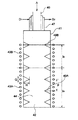
管型反応容器1は、上下方向に延在する壁により囲まれた空間を形成した管型反応容器であり、上部にシリコン析出用原料ガス流入口と、下端に析出シリコン排出口とを備え、前記管型反応容器の原料ガスと接触する壁面に流通抵抗増加部位が形成されていることを特徴とするものである。上部のシリコン析出用原料ガス流入口2より、シリコン析出用原料ガスを流通させ、反応容器の壁面(a)の空間5に面する加熱された表面でシリコンを析出・溶融せしめ、下端部にシリコンが自然流下により容器外に落下せしめる開口部(排出口3)を有するものであればその形状は特に制限されない。
流通抵抗増加部位は、管型反応容器内で、拡散を阻害する膜となる上昇流を効果的に減少させ、さらには管型反応容器の中心軸部の原料ガスを効果的に上昇流に混和させる目的で形成する。このような流通抵抗増加部位を設けることで、原料ガスの反応率向上と副生物抑制を同時に達成するが可能となる。ここで原料ガスの反応率とは、管型反応容器1の空間5に供給した原料ガスが、該空間5から排出されるまでの間に何らかの物質に転化した割合で定義される。また以下で述べるシリコンの収率とは、原料ガスが反応して何らかの物質に転化した原料ガスのうち、シリコンへ転化したものの割合と定義する。
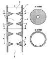
本発明の流通抵抗増加部位として最も好適な態様は突起である。突起とは、管型反応容器壁面から空間5に向かって突出したものを指す。
角があると流れにくくなるので、このようなオリフィスのうち、図1に示すような、断面が三角形のものがより好ましい。なお、三角形状は、直角三角形状や二等辺三角形状のような規則を持った形状であってもよいし、特に規則を持たない三角形であってもよい。しかしながら、オリフィスを流通抵抗増加部位として有効に機能させ、かつオリフィス下流域でのガスのよどみやこれによる温度上昇を抑制するためには、上記流通抵抗増加部位は、ガス流の下流側が上流側よりもなだらかな傾斜で形成される三角形であることが最も好ましい。すなわち、図3に示されるように、三角形と壁面との外角は、ガス流の上流側よりも下流側が鈍角であることが望ましい。また縦断面視でみる突起と管型反応容器との接点は、直線的に交わる形状であっても特に問題はないものの、表面張力の大きいシリコン融液がより滑らかに流下するように、図3に示すような曲線形状、すなわち、JISに準拠した図面記号で示されるRをつけた形状であることがより好ましい。Rは5〜10程度であればよい。
オリフィスが設けられた部位は、加熱手段にもよるが、例えば、高周波加熱する場合、高周波が集中しやすく、このため内部温度が高くなってしまうことがある。内部温度が高くなると、そこから、管型反応容器が破損することがある。このため、オリフィスが設けられた部位の外壁面側から反応器壁の厚みを減少させることにより、過熱状態とならないようにしておくことが望ましい。
例えば、図26に示されるように、半円溝状に外壁面を削っておくことが望ましい。削った溝の深さは特に制限されるものではなく、たとえば、半円形溝再深部から、オリフェス頂点までの距離が、管型反応容器の厚さに相当するように削ってもよく、さらに溝の深さが浅くとも差し支えない。溝は半円状であってもよいが、熱は、オリフェス下面に集中して、過熱状態となることが多いので、オリフェス下面付近にあたる反応容器の壁の厚さを薄くするために、半紡錘状であってもよい。このように外壁面から反応容器壁の厚みを減少させておくと、オリフェスでの熱の集中が抑制されるので、オリフェス内部の高温化が抑制され、管型反応容器の耐久性が向上する。
以上のような突起の中でも本発明ではオリフィスが好ましく、その縦断面視は三角形であることが、シリコン融液の落下という点で好適であり、さらに、その開口部は、反応容器の中心軸であると、原料ガスが反応容器のどこからも均一に加熱できるので、より好適である。
凹部は、内壁表面より凹んだ部分をいう。すなわち、凹部はその深さを反応容器1の肉厚より深くすることができないため、場合によっては突起よりもその1つあたりの効果が小さくなることがあるが、原料ガスが析出表面への拡散を阻害する上昇流を減少させ、反応容器の中心軸部の原料ガスを上昇流に混和させる機能は有する。
傾斜は、管型反応容器そのものの一部または全部が流通抵抗増加部位となる態様であるといえる。すなわち、傾斜としては、シリコン析出用ガス流の流れ方向を変化させることができるものであれば特に制限されるものではないが、例えば図12のような蛇行形状が挙げられる。図示はしないが、蛇行は螺旋状に行われていてもよい。
本発明に係るシリコンの製造方法は、前記管型反応容器を用いて、前記シリコン析出用原料ガス流入口を介して、シラン類を含むシリコン析出用原料ガスを導入して、加熱した反応容器内でシラン類を含むシリコン析出用原料ガスから多結晶シリコンを製造することを特徴としている。
また、流通抵抗増加部位として突起、特にオリフェスが設けられた場合、突起と突起の間を1ゾーンとし、加熱手段を少なくとも1ゾーンごとに分割して配置し、該突起間で反応ガスが奪う熱量に応じて最適な熱エネルギーを供給するように制御することが好ましい。
さらに、流通抵抗増加部位として突起、特にオリフェスが設けられた場合、加熱すると、突起が設けられた部位に熱が集中して2000℃以上となってしまうことがある。このような過熱状態におかれると、管型反応容器が破損して、反応容器の部材の一部が溶出して析出シリコン中に多量に混入するなどの問題点がある。
そこで、このような突起での過熱を防止するため、前記のように、突起が設けられた部位において外壁面側から反応容器壁の厚みを減少させた管型反応容器を使用してもよい。
また、他の態様として、高周波(すなわち電磁波)による加熱方法を用いて加熱する場合には、上記突起が設けられた部位における発熱量が他の部位より小さくなるように加熱手段を設ける態様が採用される。例えば、突起が設けられた部位の外壁面における加熱コイルの間隔を、他のところ(すなわち、突起が設けられていないところ)に比べて広げたり、突起が設けられた部位を避けるように加熱コイルを設置したりする態様が挙げられる。
また、高周波を遮蔽するシールドを、突起が設けられた部位の外壁面に設け、高周波を伝わりにくくさせてもよい。具体的には、高周波を遮蔽する方法として、銅板を挟み込めば、その部分への高周波エネルギー量を減少できるので、突起部位での過熱を抑制することができる。前述の反応容器壁の厚みを減少させる態様と、高周波による加熱を行う加熱コイルからの高周波エネルギー量を減少させる態様は、単独あるいは組み合わせて実施することができる。
本発明に係る管型反応容器を使用すれば、流通抵抗増加部位によって、ガス流が乱されているので、平均ガス温度を均一に高めることができる。
原料ガスの高い反応率、析出シリコンの高収率、および好ましくない副生物の低減を達成するためには、管型反応容器から排出されるガスの単位ガス量当りの平均温度は700℃以上、好ましくは、800から1500℃、より好ましくは900〜1400℃の範囲とすることが望ましい。前述した本発明に係る管型反応容器の構造、およびシリコン製造条件を採用することにより、前記ガス温度が達成され、効率よくシリコンを製造することが可能となる。なお、突起などの流通抵抗増加部位が設けられていないと均一に加熱できず、加熱されずにそのまま通過してしまうが原料が増えるので、平均ガス温度は600℃程度と低くなってしまう。
さらに、本発明では、複数本の管型反応容器を並設し、且つ、高周波等を利用する加熱手段は前記複数本の反応容器によって形成される反応容器群部の外周に、各反応管と間隙をあけて巻回して設けられてもよい。具体的には、図27に示すように、反応容器112を水平方向へ一列に配置して、この一列に並ぶ反応容器群部112a(一点鎖線内)の外周に沿って高周波加熱コイル113を巻回している。複数の管型反応容器を、その全体を囲うように巻回した一つの高周波加熱コイルで加熱することにすると、装置サイズがコンパクトなシリコン製造装置を提供することができる。高周波加熱手段の内周に沿った位置に複数本の反応容器が水平方向に並設されていれば、並設される仕方は、図27のような直線状に限られず、二列状、環状など特に限定されないが、高周波加熱手段からの高周波によって効率的に加熱を行うためには、各反応容器の管壁の少なくとも一部を高周波加熱手段内周面と近接させることが好ましい。
以下、図22の概略図に従って説明する。
以下、図23に示す概略図に従って説明する。
以下、図24の概略図に従って説明する。
リング状突起(オリフィス)の外周部を図26のようにした以外は実施例3と同様にして、シリコン析出反応を行った。
図26は、リング状突起部の周辺を拡大断面視した図である。図に示すように、リング状突起(オリフィス)の外周部を半径30mmの半円溝状に削り取り、また高周波加熱コイルは突起部を避けて設置した。この実施態様を実施例3で使用される管型反応容器の全てのリング状突起部に適用し、その他の装置、反応条件は実施例3と同様にした。
その結果、リング状突起部の表面温度は、1500℃以下に抑制され、管型反応容器材料である、等方性カーボンの劣化はほとんど観察されず、また生成したシリコン製品中のカーボン濃度も低減した。
[比較例1]
図25に示す反応容器41の内壁面に流通抵抗増加部位49を設置しない反応容器を用いるほかは、実施例1と同様な反応装置(図22参照、符号も同じ)を用い、同様な反応条件においてシリコン析出反応を行った。その結果、トリクロロシランの反応率は22%であり、シリコンの回収量は約1.6kgであった。また反応中、またシリコン微粉とシラン類オリゴマーの合計生成量は回収したシリコン量に対し3%以上であった。
2・・・シリコン析出用原料ガス流入口
3・・・析出シリコン排出口
4・・・流通抵抗増加部位
5・・・空間
21・・反応容器
21a’・・内管
21a・・外管
22・・下端開口部(析出シリコン排出口)
23、23A、23B、23C・・加熱手段
24・・空間
24A、24B・・流通抵抗増加部位
a・・・壁
I、IA、IB・・・反応部
25・・原料ガス供給管
26・・原料ガス吹き出し口
27・・冷却手段
28・・シールガス供給管
29・・排ガス排出管
30・・密閉容器
31・・シールガス供給管
32・・冷却ガス供給管
33・・冷却ジャケット
34・・冷却空間
35・・シリコン
36・・仕切り板
37・・取出口
41・・・管型反応容器
42・・・析出シリコン排出口
43・・・加熱手段
45・・・原料ガス供給管
46・・・原料ガス流入口
47・・・冷却手段
48・・・シールガス供給管
49・・・流通抵抗増加部位
51・・・環状反応容器
51(a)・・・外管
51(a’)・・・内管
52・・・析出シリコン排出口
53・・・加熱手段
55・・・原料ガス供給管
56・・・原料ガス流入口
57・・・冷却手段
58・・・流通抵抗増加部位
112・・・反応容器
112a・・・容器群部112a(一点鎖線内)
113・・・高周波加熱コイル
Claims (8)
- 上下方向に延在する壁により囲まれた空間を形成した管型反応容器であり、上部にシリコン析出用原料ガス流入口と、下端に析出シリコン排出口とを備え、前記管型反応容器の原料ガスと接触する壁面に流通抵抗増加部位が形成されており、前記流通抵抗増加部位が突起であることを特徴とする管型反応容器。
- 前記流通抵抗増加部位が、複数設置されることを特徴とする請求項1に記載の管型反応容器。
- 前記空間が、上下方向に延在する内管と外管との間により囲まれた、原料ガスが流通する空間であることを特徴とする請求項1または2に記載の管型反応容器。
- 流通抵抗増加部位が、管型反応容器において突起を設置することによって形成され、該突起が設けられた部位において、外壁面側から反応容器壁の厚みを減少せしめたことを特徴とする請求項1〜3の何れか1項に記載の管型反応容器。
- 流通抵抗増加部位が、管型反応容器に突起を設置することによって形成され、該管型反応容器を高周波加熱コイルによって加熱するようにした反応容器であり、該突起が設けられた部位において、高周波加熱コイルからの高周波エネルギーを、他の部位よりも減少させる手段を有することを特徴とする請求項1〜3の何れか1項に記載の管型反応容器。
- 上下方向に延在する壁により囲まれた空間を形成した管型反応容器であり、上部にシリコン析出用原料ガス流入口と、下端に析出シリコン排出口とを備え、前記管型反応容器の原料ガスと接触する壁面に流通抵抗増加部位が形成されており、前記流通抵抗増加部位が突起である管型反応容器を用いて、前記シリコン析出用原料ガス流入口を介して、クロロシラン類を含むシリコン析出用原料ガスを導入して、加熱した反応容器内でクロロシラン類を含むシリコン析出用原料ガスから多結晶シリコンを製造することを特徴とするシリコンの製造方法。
- 前記管型反応容器が、複数の流通抵抗増加部位が形成されたものである、請求項6に記載のシリコンの製造方法。
- 前記空間が、上下方向に延在する内管と外管との間により囲まれた、原料ガスが流通する空間である、請求項6または7に記載のシリコンの製造方法。
Priority Applications (1)
| Application Number | Priority Date | Filing Date | Title |
|---|---|---|---|
| JP2005513164A JP5291282B2 (ja) | 2003-08-13 | 2004-08-11 | 管型反応容器および該反応容器を用いたシリコンの製造方法 |
Applications Claiming Priority (4)
| Application Number | Priority Date | Filing Date | Title |
|---|---|---|---|
| JP2003293197 | 2003-08-13 | ||
| JP2003293197 | 2003-08-13 | ||
| PCT/JP2004/011542 WO2005016820A1 (ja) | 2003-08-13 | 2004-08-11 | 管型反応容器および該反応容器を用いたシリコンの製造方法 |
| JP2005513164A JP5291282B2 (ja) | 2003-08-13 | 2004-08-11 | 管型反応容器および該反応容器を用いたシリコンの製造方法 |
Publications (2)
| Publication Number | Publication Date |
|---|---|
| JPWO2005016820A1 JPWO2005016820A1 (ja) | 2007-10-04 |
| JP5291282B2 true JP5291282B2 (ja) | 2013-09-18 |
Family
ID=34190988
Family Applications (1)
| Application Number | Title | Priority Date | Filing Date |
|---|---|---|---|
| JP2005513164A Expired - Fee Related JP5291282B2 (ja) | 2003-08-13 | 2004-08-11 | 管型反応容器および該反応容器を用いたシリコンの製造方法 |
Country Status (7)
| Country | Link |
|---|---|
| US (1) | US7553467B2 (ja) |
| EP (1) | EP1661857B1 (ja) |
| JP (1) | JP5291282B2 (ja) |
| CN (1) | CN100335162C (ja) |
| AU (1) | AU2004265173B2 (ja) |
| CA (1) | CA2535537C (ja) |
| WO (1) | WO2005016820A1 (ja) |
Cited By (3)
| Publication number | Priority date | Publication date | Assignee | Title |
|---|---|---|---|---|
| KR101768279B1 (ko) | 2014-09-29 | 2017-08-30 | 주식회사 엘지화학 | 수평형 반응기를 이용한 폴리실리콘 제조 장치 및 제조 방법 |
| KR101816339B1 (ko) * | 2014-05-13 | 2018-01-08 | 주식회사 엘지화학 | 연속식 관형반응기를 이용한 클로로실란가스 제조방법 |
| KR101821006B1 (ko) * | 2014-05-13 | 2018-01-22 | 주식회사 엘지화학 | 수평형 반응기를 이용한 폴리실리콘 제조 장치 및 제조 방법 |
Families Citing this family (23)
| Publication number | Priority date | Publication date | Assignee | Title |
|---|---|---|---|---|
| KR100696501B1 (ko) | 2005-03-23 | 2007-03-19 | 삼성에스디아이 주식회사 | 플라즈마 디스플레이 장치 |
| GB2429143B (en) * | 2005-07-11 | 2008-02-13 | Re18 Ltd | Vessel and source of radio frequency electromagnetic radiation, heating apparatus and method of heating a feedstock |
| DE102006050901A1 (de) * | 2005-11-17 | 2007-05-31 | Solarworld Industries Deutschland Gmbh | Verfahren zum Herstellen eines Halbleiterkörpers und zum Herstellen einer Halbleitervorrichtung |
| KR100813131B1 (ko) * | 2006-06-15 | 2008-03-17 | 한국화학연구원 | 유동층 반응기를 이용한 다결정 실리콘의 지속 가능한제조방법 |
| US8025804B2 (en) | 2006-12-19 | 2011-09-27 | Avi Efraty | Continuous closed-circuit desalination method without containers |
| US20140131911A1 (en) * | 2007-04-25 | 2014-05-15 | Greenly Group For Solar Technologies, Ltd. | Cartridge Reactor for Production of Materials via the Chemical Vapor Deposition Process |
| CN101707871B (zh) * | 2007-04-25 | 2013-06-12 | 卡甘·塞兰 | 通过大表面积气-固或气-液界面及液相再生沉积高纯硅 |
| JP5334490B2 (ja) * | 2008-08-06 | 2013-11-06 | 株式会社トクヤマ | シリコン製造装置 |
| WO2010016133A1 (ja) * | 2008-08-07 | 2010-02-11 | 電気化学工業株式会社 | カーボン製反応装置 |
| CN102639438B (zh) * | 2009-11-25 | 2016-04-13 | 戴纳泰克工程有限公司 | 用于生产硅的反应器和方法 |
| KR101329030B1 (ko) * | 2010-10-01 | 2013-11-13 | 주식회사 실리콘밸류 | 유동층 반응기 |
| CN107675250B (zh) * | 2011-03-28 | 2020-08-07 | 应用材料公司 | 选择性沉积外延锗合金应力源的方法与设备 |
| JP5653857B2 (ja) * | 2011-07-25 | 2015-01-14 | 株式会社トクヤマ | ポリシリコン受け容器 |
| NO334776B1 (no) | 2011-09-26 | 2014-05-26 | Dynatec Engineering As | Reaktor og fremgangsmåte for fremstilling av silisium ved kjemisk dampavsetning |
| JP5995188B2 (ja) * | 2012-05-08 | 2016-09-21 | Jfeエンジニアリング株式会社 | 静止型混合装置及びこれを有するバラスト水処理装置 |
| CN102879362B (zh) * | 2012-09-19 | 2016-03-30 | 有色金属矿产地质调查中心 | 一种用于原子荧光光谱仪气体传输系统的集扩式混匀模块 |
| GB201505803D0 (en) * | 2015-04-02 | 2015-05-20 | Hanovia Ltd | Conditioning and treating a fluid flow |
| CN105546348A (zh) * | 2015-12-09 | 2016-05-04 | 无锡拓能自动化科技有限公司 | 应用于气体灌装站的高效混合气体灌装管道 |
| CN105546349A (zh) * | 2015-12-09 | 2016-05-04 | 无锡拓能自动化科技有限公司 | 应用于气体灌装站的气体灌装管道 |
| WO2017127925A1 (en) * | 2016-01-26 | 2017-08-03 | Michael Ransom | Apparatus for mixing fluids, including fluids containing solids |
| CN107021606B (zh) * | 2017-04-20 | 2020-01-03 | 江苏太平洋石英股份有限公司 | 连熔法生产光纤用外套管的方法 |
| FR3077511B1 (fr) * | 2018-02-08 | 2022-07-22 | Total Raffinage Chimie | Dispositif d'injection de charge d'une unite fcc. |
| JP7088774B2 (ja) * | 2018-07-31 | 2022-06-21 | 株式会社トクヤマ | シリコン微粒子製造装置 |
Citations (4)
| Publication number | Priority date | Publication date | Assignee | Title |
|---|---|---|---|---|
| US4374093A (en) * | 1981-02-20 | 1983-02-15 | Mobil Oil Corporation | Continuous-stream upflow zeolite crystallization apparatus |
| JP2002029726A (ja) * | 2000-05-11 | 2002-01-29 | Tokuyama Corp | シリコン生成用反応装置 |
| WO2002029219A1 (de) * | 2000-10-04 | 2002-04-11 | Robert Bosch Gmbh | Vorrichtung zur bildung eines reduktionsmittel-abgas-gemisches und abgasreinigungsanlage |
| JP2003002626A (ja) * | 2001-06-18 | 2003-01-08 | Tokuyama Corp | シリコン生成用反応装置 |
Family Cites Families (6)
| Publication number | Priority date | Publication date | Assignee | Title |
|---|---|---|---|---|
| US4547258A (en) | 1982-12-22 | 1985-10-15 | Texas Instruments Incorporated | Deposition of silicon at temperatures above its melting point |
| US4710260A (en) | 1982-12-22 | 1987-12-01 | Texas Instruments Incorporated | Deposition of silicon at temperatures above its melting point |
| US5146869A (en) * | 1990-06-11 | 1992-09-15 | National Semiconductor Corporation | Tube and injector for preheating gases in a chemical vapor deposition reactor |
| CA2386382A1 (en) * | 2000-02-18 | 2001-08-23 | G.T. Equipment Technologies, Inc. | Method and apparatus for chemical vapor deposition of polysilicon |
| CN100406378C (zh) | 2000-05-11 | 2008-07-30 | 德山株式会社 | 多晶硅的生产装置 |
| JP4639005B2 (ja) * | 2001-07-03 | 2011-02-23 | 株式会社トクヤマ | シリコンおよびトリクロロシランの製造法 |
-
2004
- 2004-08-11 AU AU2004265173A patent/AU2004265173B2/en not_active Ceased
- 2004-08-11 JP JP2005513164A patent/JP5291282B2/ja not_active Expired - Fee Related
- 2004-08-11 WO PCT/JP2004/011542 patent/WO2005016820A1/ja active Application Filing
- 2004-08-11 US US10/567,943 patent/US7553467B2/en active Active
- 2004-08-11 CN CNB2004800010421A patent/CN100335162C/zh not_active Expired - Fee Related
- 2004-08-11 EP EP04771527.1A patent/EP1661857B1/en not_active Expired - Fee Related
- 2004-08-11 CA CA002535537A patent/CA2535537C/en not_active Expired - Fee Related
Patent Citations (4)
| Publication number | Priority date | Publication date | Assignee | Title |
|---|---|---|---|---|
| US4374093A (en) * | 1981-02-20 | 1983-02-15 | Mobil Oil Corporation | Continuous-stream upflow zeolite crystallization apparatus |
| JP2002029726A (ja) * | 2000-05-11 | 2002-01-29 | Tokuyama Corp | シリコン生成用反応装置 |
| WO2002029219A1 (de) * | 2000-10-04 | 2002-04-11 | Robert Bosch Gmbh | Vorrichtung zur bildung eines reduktionsmittel-abgas-gemisches und abgasreinigungsanlage |
| JP2003002626A (ja) * | 2001-06-18 | 2003-01-08 | Tokuyama Corp | シリコン生成用反応装置 |
Cited By (4)
| Publication number | Priority date | Publication date | Assignee | Title |
|---|---|---|---|---|
| KR101816339B1 (ko) * | 2014-05-13 | 2018-01-08 | 주식회사 엘지화학 | 연속식 관형반응기를 이용한 클로로실란가스 제조방법 |
| KR101821006B1 (ko) * | 2014-05-13 | 2018-01-22 | 주식회사 엘지화학 | 수평형 반응기를 이용한 폴리실리콘 제조 장치 및 제조 방법 |
| US10196273B2 (en) | 2014-05-13 | 2019-02-05 | Lg Chem, Ltd. | Device for manufacturing polysilicon using horizontal reactor and method for manufacturing same |
| KR101768279B1 (ko) | 2014-09-29 | 2017-08-30 | 주식회사 엘지화학 | 수평형 반응기를 이용한 폴리실리콘 제조 장치 및 제조 방법 |
Also Published As
| Publication number | Publication date |
|---|---|
| JPWO2005016820A1 (ja) | 2007-10-04 |
| AU2004265173B2 (en) | 2010-05-27 |
| AU2004265173A1 (en) | 2005-02-24 |
| EP1661857B1 (en) | 2016-12-21 |
| CA2535537C (en) | 2009-10-13 |
| US7553467B2 (en) | 2009-06-30 |
| CA2535537A1 (en) | 2005-02-24 |
| CN100335162C (zh) | 2007-09-05 |
| WO2005016820A1 (ja) | 2005-02-24 |
| US20060219161A1 (en) | 2006-10-05 |
| EP1661857A4 (en) | 2009-07-15 |
| EP1661857A1 (en) | 2006-05-31 |
| CN1735563A (zh) | 2006-02-15 |
Similar Documents
| Publication | Publication Date | Title |
|---|---|---|
| JP5291282B2 (ja) | 管型反応容器および該反応容器を用いたシリコンの製造方法 | |
| JP4290647B2 (ja) | シリコン製造用反応装置 | |
| US9764960B2 (en) | Method and apparatus for preparation of granular polysilicon | |
| JP4988741B2 (ja) | 流動床反応器中で粒状の多結晶ケイ素を製造する方法および装置 | |
| KR100210261B1 (ko) | 발열반응을 이용한 다결정 실리콘의 제조 방법 | |
| JP4597863B2 (ja) | シリコン製造装置 | |
| JP4157281B2 (ja) | シリコン生成用反応装置 | |
| JP4805155B2 (ja) | シリコン製造装置 | |
| JP4639004B2 (ja) | シリコン製造装置および製造方法 | |
| US20170283266A1 (en) | Poly-silicon manufacturing apparatus and method using high-efficiency hybrid horizontal reactor | |
| US20180051373A1 (en) | Mechanically vibrated based reactor systems and methods | |
| JPS58176924A (ja) | 純粋な半導体材料の製法及びその装置 | |
| US10196273B2 (en) | Device for manufacturing polysilicon using horizontal reactor and method for manufacturing same | |
| JP4099322B2 (ja) | シリコンの製造方法 | |
| EP2633096A1 (en) | Thermal shield for silicon production reactors | |
| WO2011071032A1 (ja) | 多結晶シリコンの製造方法及び多結晶シリコン製造用の反応炉 | |
| KR101871019B1 (ko) | 폴리실리콘의 제조 장치 및 이를 이용한 폴리실리콘 제조방법 | |
| JP2013071881A (ja) | 多結晶シリコンの製造方法 |
Legal Events
| Date | Code | Title | Description |
|---|---|---|---|
| A131 | Notification of reasons for refusal |
Free format text: JAPANESE INTERMEDIATE CODE: A131 Effective date: 20100727 |
|
| A521 | Request for written amendment filed |
Free format text: JAPANESE INTERMEDIATE CODE: A523 Effective date: 20100924 |
|
| A131 | Notification of reasons for refusal |
Free format text: JAPANESE INTERMEDIATE CODE: A131 Effective date: 20110927 |
|
| RD02 | Notification of acceptance of power of attorney |
Free format text: JAPANESE INTERMEDIATE CODE: A7422 Effective date: 20120203 |
|
| A131 | Notification of reasons for refusal |
Free format text: JAPANESE INTERMEDIATE CODE: A131 Effective date: 20120821 |
|
| A521 | Request for written amendment filed |
Free format text: JAPANESE INTERMEDIATE CODE: A523 Effective date: 20121018 |
|
| TRDD | Decision of grant or rejection written | ||
| A01 | Written decision to grant a patent or to grant a registration (utility model) |
Free format text: JAPANESE INTERMEDIATE CODE: A01 Effective date: 20130514 |
|
| A61 | First payment of annual fees (during grant procedure) |
Free format text: JAPANESE INTERMEDIATE CODE: A61 Effective date: 20130607 |
|
| R150 | Certificate of patent or registration of utility model |
Ref document number: 5291282 Country of ref document: JP Free format text: JAPANESE INTERMEDIATE CODE: R150 |
|
| LAPS | Cancellation because of no payment of annual fees |