EP1661857B1 - Tubular reaction vessel and process for producing silicon therewith - Google Patents
Tubular reaction vessel and process for producing silicon therewith Download PDFInfo
- Publication number
- EP1661857B1 EP1661857B1 EP04771527.1A EP04771527A EP1661857B1 EP 1661857 B1 EP1661857 B1 EP 1661857B1 EP 04771527 A EP04771527 A EP 04771527A EP 1661857 B1 EP1661857 B1 EP 1661857B1
- Authority
- EP
- European Patent Office
- Prior art keywords
- reaction vessel
- silicon
- feedstock gas
- tubular reaction
- reaction
- Prior art date
- Legal status (The legal status is an assumption and is not a legal conclusion. Google has not performed a legal analysis and makes no representation as to the accuracy of the status listed.)
- Expired - Fee Related
Links
- 238000006243 chemical reaction Methods 0.000 title claims description 321
- XUIMIQQOPSSXEZ-UHFFFAOYSA-N Silicon Chemical compound [Si] XUIMIQQOPSSXEZ-UHFFFAOYSA-N 0.000 title claims description 196
- 229910052710 silicon Inorganic materials 0.000 title claims description 196
- 239000010703 silicon Substances 0.000 title claims description 196
- 238000000034 method Methods 0.000 title claims description 20
- 230000008569 process Effects 0.000 title claims description 10
- 238000010438 heat treatment Methods 0.000 claims description 125
- 230000008021 deposition Effects 0.000 claims description 67
- KOPOQZFJUQMUML-UHFFFAOYSA-N chlorosilane Chemical compound Cl[SiH3] KOPOQZFJUQMUML-UHFFFAOYSA-N 0.000 claims description 7
- 239000005046 Chlorosilane Substances 0.000 claims description 6
- 229910021420 polycrystalline silicon Inorganic materials 0.000 claims description 3
- 239000007789 gas Substances 0.000 description 177
- 238000000151 deposition Methods 0.000 description 64
- 238000004519 manufacturing process Methods 0.000 description 39
- 238000001816 cooling Methods 0.000 description 19
- ZDHXKXAHOVTTAH-UHFFFAOYSA-N trichlorosilane Chemical compound Cl[SiH](Cl)Cl ZDHXKXAHOVTTAH-UHFFFAOYSA-N 0.000 description 18
- 239000005052 trichlorosilane Substances 0.000 description 18
- BLRPTPMANUNPDV-UHFFFAOYSA-N Silane Chemical compound [SiH4] BLRPTPMANUNPDV-UHFFFAOYSA-N 0.000 description 17
- 239000006227 byproduct Substances 0.000 description 17
- 239000000463 material Substances 0.000 description 15
- OKTJSMMVPCPJKN-UHFFFAOYSA-N Carbon Chemical compound [C] OKTJSMMVPCPJKN-UHFFFAOYSA-N 0.000 description 13
- 229910000077 silane Inorganic materials 0.000 description 13
- 239000001257 hydrogen Substances 0.000 description 11
- 229910052739 hydrogen Inorganic materials 0.000 description 11
- 238000002844 melting Methods 0.000 description 11
- 230000008018 melting Effects 0.000 description 11
- 239000000843 powder Substances 0.000 description 10
- UFHFLCQGNIYNRP-UHFFFAOYSA-N Hydrogen Chemical compound [H][H] UFHFLCQGNIYNRP-UHFFFAOYSA-N 0.000 description 9
- 230000000694 effects Effects 0.000 description 8
- 229910052799 carbon Inorganic materials 0.000 description 7
- 239000000203 mixture Substances 0.000 description 7
- 229910002804 graphite Inorganic materials 0.000 description 6
- 239000010439 graphite Substances 0.000 description 6
- 239000012212 insulator Substances 0.000 description 6
- 230000007774 longterm Effects 0.000 description 6
- 230000009467 reduction Effects 0.000 description 6
- 238000007865 diluting Methods 0.000 description 5
- 239000000945 filler Substances 0.000 description 5
- 238000013021 overheating Methods 0.000 description 5
- 230000002093 peripheral effect Effects 0.000 description 5
- 238000011084 recovery Methods 0.000 description 5
- 238000009792 diffusion process Methods 0.000 description 4
- 239000003507 refrigerant Substances 0.000 description 4
- 239000007787 solid Substances 0.000 description 4
- XLYOFNOQVPJJNP-UHFFFAOYSA-N water Substances O XLYOFNOQVPJJNP-UHFFFAOYSA-N 0.000 description 4
- 229920000049 Carbon (fiber) Polymers 0.000 description 3
- 229910052581 Si3N4 Inorganic materials 0.000 description 3
- 239000004917 carbon fiber Substances 0.000 description 3
- 239000003575 carbonaceous material Substances 0.000 description 3
- 239000002131 composite material Substances 0.000 description 3
- 239000000112 cooling gas Substances 0.000 description 3
- 238000004817 gas chromatography Methods 0.000 description 3
- 230000006872 improvement Effects 0.000 description 3
- VNWKTOKETHGBQD-UHFFFAOYSA-N methane Chemical compound C VNWKTOKETHGBQD-UHFFFAOYSA-N 0.000 description 3
- 238000005192 partition Methods 0.000 description 3
- 230000002265 prevention Effects 0.000 description 3
- 238000013341 scale-up Methods 0.000 description 3
- 150000004756 silanes Chemical class 0.000 description 3
- HQVNEWCFYHHQES-UHFFFAOYSA-N silicon nitride Chemical compound N12[Si]34N5[Si]62N3[Si]51N64 HQVNEWCFYHHQES-UHFFFAOYSA-N 0.000 description 3
- 229910001220 stainless steel Inorganic materials 0.000 description 3
- 239000010935 stainless steel Substances 0.000 description 3
- VXEGSRKPIUDPQT-UHFFFAOYSA-N 4-[4-(4-methoxyphenyl)piperazin-1-yl]aniline Chemical compound C1=CC(OC)=CC=C1N1CCN(C=2C=CC(N)=CC=2)CC1 VXEGSRKPIUDPQT-UHFFFAOYSA-N 0.000 description 2
- XKRFYHLGVUSROY-UHFFFAOYSA-N Argon Chemical compound [Ar] XKRFYHLGVUSROY-UHFFFAOYSA-N 0.000 description 2
- IJGRMHOSHXDMSA-UHFFFAOYSA-N Atomic nitrogen Chemical compound N#N IJGRMHOSHXDMSA-UHFFFAOYSA-N 0.000 description 2
- VEXZGXHMUGYJMC-UHFFFAOYSA-N Hydrochloric acid Chemical compound Cl VEXZGXHMUGYJMC-UHFFFAOYSA-N 0.000 description 2
- XEEYBQQBJWHFJM-UHFFFAOYSA-N Iron Chemical compound [Fe] XEEYBQQBJWHFJM-UHFFFAOYSA-N 0.000 description 2
- 230000008859 change Effects 0.000 description 2
- 230000000052 comparative effect Effects 0.000 description 2
- 238000011109 contamination Methods 0.000 description 2
- 238000009826 distribution Methods 0.000 description 2
- 238000005530 etching Methods 0.000 description 2
- 150000002431 hydrogen Chemical class 0.000 description 2
- 229910000041 hydrogen chloride Inorganic materials 0.000 description 2
- IXCSERBJSXMMFS-UHFFFAOYSA-N hydrogen chloride Substances Cl.Cl IXCSERBJSXMMFS-UHFFFAOYSA-N 0.000 description 2
- 230000002401 inhibitory effect Effects 0.000 description 2
- 230000001788 irregular Effects 0.000 description 2
- 238000002156 mixing Methods 0.000 description 2
- 239000003921 oil Substances 0.000 description 2
- 239000002296 pyrolytic carbon Substances 0.000 description 2
- 239000012495 reaction gas Substances 0.000 description 2
- HBMJWWWQQXIZIP-UHFFFAOYSA-N silicon carbide Chemical compound [Si+]#[C-] HBMJWWWQQXIZIP-UHFFFAOYSA-N 0.000 description 2
- 239000005049 silicon tetrachloride Substances 0.000 description 2
- 239000000126 substance Substances 0.000 description 2
- 238000011144 upstream manufacturing Methods 0.000 description 2
- PIGFYZPCRLYGLF-UHFFFAOYSA-N Aluminum nitride Chemical compound [Al]#N PIGFYZPCRLYGLF-UHFFFAOYSA-N 0.000 description 1
- PZNSFCLAULLKQX-UHFFFAOYSA-N Boron nitride Chemical compound N#B PZNSFCLAULLKQX-UHFFFAOYSA-N 0.000 description 1
- RYGMFSIKBFXOCR-UHFFFAOYSA-N Copper Chemical compound [Cu] RYGMFSIKBFXOCR-UHFFFAOYSA-N 0.000 description 1
- 229910003822 SiHCl3 Inorganic materials 0.000 description 1
- 229910052786 argon Inorganic materials 0.000 description 1
- 230000008901 benefit Effects 0.000 description 1
- 230000005540 biological transmission Effects 0.000 description 1
- 230000015572 biosynthetic process Effects 0.000 description 1
- 229910010293 ceramic material Inorganic materials 0.000 description 1
- 229910052802 copper Inorganic materials 0.000 description 1
- 239000010949 copper Substances 0.000 description 1
- 125000004122 cyclic group Chemical group 0.000 description 1
- 238000000354 decomposition reaction Methods 0.000 description 1
- 230000003247 decreasing effect Effects 0.000 description 1
- 238000005137 deposition process Methods 0.000 description 1
- 230000000994 depressogenic effect Effects 0.000 description 1
- 230000006866 deterioration Effects 0.000 description 1
- 230000001627 detrimental effect Effects 0.000 description 1
- MROCJMGDEKINLD-UHFFFAOYSA-N dichlorosilane Chemical compound Cl[SiH2]Cl MROCJMGDEKINLD-UHFFFAOYSA-N 0.000 description 1
- 238000010790 dilution Methods 0.000 description 1
- 239000012895 dilution Substances 0.000 description 1
- 230000003292 diminished effect Effects 0.000 description 1
- 230000008030 elimination Effects 0.000 description 1
- 238000003379 elimination reaction Methods 0.000 description 1
- 230000002349 favourable effect Effects 0.000 description 1
- 230000005484 gravity Effects 0.000 description 1
- 239000001307 helium Substances 0.000 description 1
- 229910052734 helium Inorganic materials 0.000 description 1
- SWQJXJOGLNCZEY-UHFFFAOYSA-N helium atom Chemical compound [He] SWQJXJOGLNCZEY-UHFFFAOYSA-N 0.000 description 1
- 239000012535 impurity Substances 0.000 description 1
- 230000006698 induction Effects 0.000 description 1
- 238000009776 industrial production Methods 0.000 description 1
- 239000011261 inert gas Substances 0.000 description 1
- 229910052742 iron Inorganic materials 0.000 description 1
- 238000010667 large scale reaction Methods 0.000 description 1
- 230000007246 mechanism Effects 0.000 description 1
- 230000004048 modification Effects 0.000 description 1
- 238000012986 modification Methods 0.000 description 1
- 238000000465 moulding Methods 0.000 description 1
- 229910052757 nitrogen Inorganic materials 0.000 description 1
- 239000000047 product Substances 0.000 description 1
- 230000005855 radiation Effects 0.000 description 1
- 239000004065 semiconductor Substances 0.000 description 1
- 229910010271 silicon carbide Inorganic materials 0.000 description 1
- 239000002210 silicon-based material Substances 0.000 description 1
- 238000005406 washing Methods 0.000 description 1
Images


Classifications
-
- B—PERFORMING OPERATIONS; TRANSPORTING
- B01—PHYSICAL OR CHEMICAL PROCESSES OR APPARATUS IN GENERAL
- B01F—MIXING, e.g. DISSOLVING, EMULSIFYING OR DISPERSING
- B01F23/00—Mixing according to the phases to be mixed, e.g. dispersing or emulsifying
- B01F23/10—Mixing gases with gases
-
- B—PERFORMING OPERATIONS; TRANSPORTING
- B01—PHYSICAL OR CHEMICAL PROCESSES OR APPARATUS IN GENERAL
- B01J—CHEMICAL OR PHYSICAL PROCESSES, e.g. CATALYSIS OR COLLOID CHEMISTRY; THEIR RELEVANT APPARATUS
- B01J19/00—Chemical, physical or physico-chemical processes in general; Their relevant apparatus
- B01J19/0053—Details of the reactor
-
- B—PERFORMING OPERATIONS; TRANSPORTING
- B01—PHYSICAL OR CHEMICAL PROCESSES OR APPARATUS IN GENERAL
- B01F—MIXING, e.g. DISSOLVING, EMULSIFYING OR DISPERSING
- B01F25/00—Flow mixers; Mixers for falling materials, e.g. solid particles
- B01F25/40—Static mixers
- B01F25/42—Static mixers in which the mixing is affected by moving the components jointly in changing directions, e.g. in tubes provided with baffles or obstructions
- B01F25/43—Mixing tubes, e.g. wherein the material is moved in a radial or partly reversed direction
- B01F25/431—Straight mixing tubes with baffles or obstructions that do not cause substantial pressure drop; Baffles therefor
- B01F25/4316—Straight mixing tubes with baffles or obstructions that do not cause substantial pressure drop; Baffles therefor the baffles being flat pieces of material, e.g. intermeshing, fixed to the wall or fixed on a central rod
- B01F25/43161—Straight mixing tubes with baffles or obstructions that do not cause substantial pressure drop; Baffles therefor the baffles being flat pieces of material, e.g. intermeshing, fixed to the wall or fixed on a central rod composed of consecutive sections of flat pieces of material
-
- B—PERFORMING OPERATIONS; TRANSPORTING
- B01—PHYSICAL OR CHEMICAL PROCESSES OR APPARATUS IN GENERAL
- B01F—MIXING, e.g. DISSOLVING, EMULSIFYING OR DISPERSING
- B01F25/00—Flow mixers; Mixers for falling materials, e.g. solid particles
- B01F25/40—Static mixers
- B01F25/42—Static mixers in which the mixing is affected by moving the components jointly in changing directions, e.g. in tubes provided with baffles or obstructions
- B01F25/43—Mixing tubes, e.g. wherein the material is moved in a radial or partly reversed direction
- B01F25/431—Straight mixing tubes with baffles or obstructions that do not cause substantial pressure drop; Baffles therefor
- B01F25/43197—Straight mixing tubes with baffles or obstructions that do not cause substantial pressure drop; Baffles therefor characterised by the mounting of the baffles or obstructions
- B01F25/431971—Mounted on the wall
-
- B—PERFORMING OPERATIONS; TRANSPORTING
- B01—PHYSICAL OR CHEMICAL PROCESSES OR APPARATUS IN GENERAL
- B01F—MIXING, e.g. DISSOLVING, EMULSIFYING OR DISPERSING
- B01F25/00—Flow mixers; Mixers for falling materials, e.g. solid particles
- B01F25/40—Static mixers
- B01F25/42—Static mixers in which the mixing is affected by moving the components jointly in changing directions, e.g. in tubes provided with baffles or obstructions
- B01F25/43—Mixing tubes, e.g. wherein the material is moved in a radial or partly reversed direction
- B01F25/431—Straight mixing tubes with baffles or obstructions that do not cause substantial pressure drop; Baffles therefor
- B01F25/43197—Straight mixing tubes with baffles or obstructions that do not cause substantial pressure drop; Baffles therefor characterised by the mounting of the baffles or obstructions
- B01F25/431972—Mounted on an axial support member, e.g. a rod or bar
-
- B—PERFORMING OPERATIONS; TRANSPORTING
- B01—PHYSICAL OR CHEMICAL PROCESSES OR APPARATUS IN GENERAL
- B01F—MIXING, e.g. DISSOLVING, EMULSIFYING OR DISPERSING
- B01F25/00—Flow mixers; Mixers for falling materials, e.g. solid particles
- B01F25/40—Static mixers
- B01F25/42—Static mixers in which the mixing is affected by moving the components jointly in changing directions, e.g. in tubes provided with baffles or obstructions
- B01F25/43—Mixing tubes, e.g. wherein the material is moved in a radial or partly reversed direction
- B01F25/433—Mixing tubes wherein the shape of the tube influences the mixing, e.g. mixing tubes with varying cross-section or provided with inwardly extending profiles
- B01F25/4331—Mixers with bended, curved, coiled, wounded mixing tubes or comprising elements for bending the flow
-
- B—PERFORMING OPERATIONS; TRANSPORTING
- B01—PHYSICAL OR CHEMICAL PROCESSES OR APPARATUS IN GENERAL
- B01F—MIXING, e.g. DISSOLVING, EMULSIFYING OR DISPERSING
- B01F25/00—Flow mixers; Mixers for falling materials, e.g. solid particles
- B01F25/40—Static mixers
- B01F25/42—Static mixers in which the mixing is affected by moving the components jointly in changing directions, e.g. in tubes provided with baffles or obstructions
- B01F25/43—Mixing tubes, e.g. wherein the material is moved in a radial or partly reversed direction
- B01F25/433—Mixing tubes wherein the shape of the tube influences the mixing, e.g. mixing tubes with varying cross-section or provided with inwardly extending profiles
- B01F25/4333—Mixers with scallop-shaped tubes or surfaces facing each other
-
- B—PERFORMING OPERATIONS; TRANSPORTING
- B01—PHYSICAL OR CHEMICAL PROCESSES OR APPARATUS IN GENERAL
- B01F—MIXING, e.g. DISSOLVING, EMULSIFYING OR DISPERSING
- B01F25/00—Flow mixers; Mixers for falling materials, e.g. solid particles
- B01F25/40—Static mixers
- B01F25/42—Static mixers in which the mixing is affected by moving the components jointly in changing directions, e.g. in tubes provided with baffles or obstructions
- B01F25/43—Mixing tubes, e.g. wherein the material is moved in a radial or partly reversed direction
- B01F25/433—Mixing tubes wherein the shape of the tube influences the mixing, e.g. mixing tubes with varying cross-section or provided with inwardly extending profiles
- B01F25/4338—Mixers with a succession of converging-diverging cross-sections, i.e. undulating cross-section
-
- B—PERFORMING OPERATIONS; TRANSPORTING
- B01—PHYSICAL OR CHEMICAL PROCESSES OR APPARATUS IN GENERAL
- B01J—CHEMICAL OR PHYSICAL PROCESSES, e.g. CATALYSIS OR COLLOID CHEMISTRY; THEIR RELEVANT APPARATUS
- B01J19/00—Chemical, physical or physico-chemical processes in general; Their relevant apparatus
- B01J19/24—Stationary reactors without moving elements inside
- B01J19/2415—Tubular reactors
- B01J19/2425—Tubular reactors in parallel
-
- B—PERFORMING OPERATIONS; TRANSPORTING
- B01—PHYSICAL OR CHEMICAL PROCESSES OR APPARATUS IN GENERAL
- B01J—CHEMICAL OR PHYSICAL PROCESSES, e.g. CATALYSIS OR COLLOID CHEMISTRY; THEIR RELEVANT APPARATUS
- B01J19/00—Chemical, physical or physico-chemical processes in general; Their relevant apparatus
- B01J19/24—Stationary reactors without moving elements inside
- B01J19/2415—Tubular reactors
- B01J19/244—Concentric tubes
-
- C—CHEMISTRY; METALLURGY
- C01—INORGANIC CHEMISTRY
- C01B—NON-METALLIC ELEMENTS; COMPOUNDS THEREOF; METALLOIDS OR COMPOUNDS THEREOF NOT COVERED BY SUBCLASS C01C
- C01B33/00—Silicon; Compounds thereof
- C01B33/02—Silicon
-
- C—CHEMISTRY; METALLURGY
- C01—INORGANIC CHEMISTRY
- C01B—NON-METALLIC ELEMENTS; COMPOUNDS THEREOF; METALLOIDS OR COMPOUNDS THEREOF NOT COVERED BY SUBCLASS C01C
- C01B33/00—Silicon; Compounds thereof
- C01B33/02—Silicon
- C01B33/021—Preparation
- C01B33/027—Preparation by decomposition or reduction of gaseous or vaporised silicon compounds other than silica or silica-containing material
- C01B33/03—Preparation by decomposition or reduction of gaseous or vaporised silicon compounds other than silica or silica-containing material by decomposition of silicon halides or halosilanes or reduction thereof with hydrogen as the only reducing agent
-
- B—PERFORMING OPERATIONS; TRANSPORTING
- B01—PHYSICAL OR CHEMICAL PROCESSES OR APPARATUS IN GENERAL
- B01J—CHEMICAL OR PHYSICAL PROCESSES, e.g. CATALYSIS OR COLLOID CHEMISTRY; THEIR RELEVANT APPARATUS
- B01J2219/00—Chemical, physical or physico-chemical processes in general; Their relevant apparatus
- B01J2219/00002—Chemical plants
- B01J2219/00004—Scale aspects
- B01J2219/00015—Scale-up
-
- Y—GENERAL TAGGING OF NEW TECHNOLOGICAL DEVELOPMENTS; GENERAL TAGGING OF CROSS-SECTIONAL TECHNOLOGIES SPANNING OVER SEVERAL SECTIONS OF THE IPC; TECHNICAL SUBJECTS COVERED BY FORMER USPC CROSS-REFERENCE ART COLLECTIONS [XRACs] AND DIGESTS
- Y10—TECHNICAL SUBJECTS COVERED BY FORMER USPC
- Y10T—TECHNICAL SUBJECTS COVERED BY FORMER US CLASSIFICATION
- Y10T117/00—Single-crystal, oriented-crystal, and epitaxy growth processes; non-coating apparatus therefor
- Y10T117/10—Apparatus
- Y10T117/1024—Apparatus for crystallization from liquid or supercritical state
- Y10T117/1028—Crucibleless apparatus having means providing movement of discrete droplets or solid particles to thin-film precursor [e.g., Verneuil method]
Definitions
- the present invention relates to a novel reaction vessel for producing silicon from a silicon deposition feedstock gas containing a chlorosilane and hydrogen. More particularly, the invention relates to a reaction vessel that permits stable and efficient silicon production over extended periods and enables reduction of by-products to an extremely low level. The invention also relates to a silicon production process using the reaction vessel.
- Siemens process in which a silicon rod heated by energization to a silicon deposition temperature is placed in a bell jar, and trichlorosilane (SiHCl 3 , hereinafter TCS) or monosilane (SiH 4 ) together with a reducing gas such as hydrogen are brought into contact with the rod to deposit silicon.
- TCS trichlorosilane
- SiH 4 monosilane
- This process provides high-purity silicon and is performed most commonly. Because of batchwise deposition, however, the process has a problem of a very complicated procedure including placement of the silicon rod as a seedbed, energization heating, deposition, cooling and takeout of the silicon rod, as well as bell jar washing.
- Patent Document 1 JP-A-2002-29726 .
- the reactor is structured such that a silicon deposition feedstock gas is supplied into a tubular reaction vessel resistant to temperatures in excess of the melting point of silicon, the tubular reaction vessel is heated to deposit silicon, and the deposited silicon is molten and continually drips down from the lower end of the tubular reaction vessel and is recovered.
- Patent Document 2 JP-A-S59-162117 .
- the silicon deposition reaction vessel is generally heated inside by heat conduction from external heating means, and therefore heat cannot reach deep into the filler layer. As a result, a great temperature difference is caused within the filler layer between the vicinity of the reaction vessel wall and the vicinity of the filler layer central axis.
- the upward flow blocks diffusion of the feedstock gas to the deposition surface and the feedstock gas reaction efficiency is just lowered, but, accidental local gas turbulence brings part of the high-temperature upward flow into contact with part of the low-temperature feedstock gas, with formation of by-products.
- the upward flow reduces the possibility that the formed by-products will be recontacted with the deposition surface, so that most of the by-products are discharged from the reaction vessel.
- the present inventors further studied to scale up the Patent Document 1 reaction vessel while maintaining the reaction efficiency and preventing occurrence of the by-products.
- the reaction vessel internal wall With flow resistance-increasing regions, not only the diffusion-blocking upward flow can be effectively diminished but also the feedstock gas in the vicinity of the reaction vessel central axis can be effectively mixed with the upward flow.
- they have succeeded in achieving both improvement of the feedstock gas reaction efficiency and prevention of the by-products.
- the feedstock gas can be effectively contacted with the deposition surface as described above, thereby, silicon fine powder and the like can be recontacted with the deposition surface and be incorporated in the deposit.
- the feedstock gas supplied is uniformly heated to high temperatures, the silane oligomer can be re-decomposed, therefore, the by-products discharged from the reaction vessel can be dramatically reduced.
- the present inventors further studied and found that reduction of temperature variation in the reaction vessel internal wall, reduction of flow resistance of the feedstock gas, and smooth drop of the silicon melt are achieved when the shape, size and arrangement of the flow resistance-increasing regions are adequately setting.
- the present invention has been completed based on the aforesaid findings.
- the output distribution of heating apparatus can also be leveled out, leading to reduced operating cost.
- the present invention provides a tubular reaction vessel comprising a longitudinally-extending wall with a space thereinside, wherein a silicon deposition feedstock gas inflow opening and a deposited silicon discharge opening are provided at an upper portion and a lower end portion respectively, and a plurality of flow resistance-increasing regions are created on a wall surface of the tubular reaction vessel that is contacted with a feedstock gas, wherein each flow resistance-increasing region is at least one of protrudent or concave regions.
- the feedstock gas can be uniformly and sufficiently heated by means of a very large deposition surface inside the reaction vessel, so that the potential silicon production capability of the feedstock gas can be fully educed while preventing by-products, thereby, the present invention achieves both high silicon production efficiency and long-term stable operation.
- the silicon deposition reaction vessel can be scaled up to industrial large-scale equipment while permitting the silicon deposition feedstock gas to react effectively and silicon to be mass produced stably over a long term.
- the flow resistance-increasing region is a protrusion provided in the tubular reaction vessel, and the reaction vessel is reduced in thickness from the external wall in the protrusion-provided area.
- the flow resistance-increasing region is a protrusion provided in the tubular reaction vessel, and the tubular reaction vessel is arranged to be heated by a high frequency heating coil and includes means for reducing high frequency energy from the high frequency heating coil in the protrusion-provided area relative to the other area.
- the present invention also provides a process for producing silicon, comprising: providing a tubular reaction vessel that comprises a longitudinally-extending wall with a space thereinside, wherein a silicon deposition feedstock gas inflow opening and a deposited silicon discharge opening are provided at an upper portion and a lower end portion respectively, and a plurality of flow resistance-increasing regions are created on a wall surface of the tubular reaction vessel that is contacted with a feedstock gas, wherein each flow resistance-increasing region is at least one of protrudent or concave regions; introducing a silicon deposition feedstock gas containing a chlorosilane through the silicon deposition feedstock gas inflow opening; and producing polycrystalline silicon from the chlorosilane-containing silicon deposition feedstock gas in the heated reaction vessel.
- the invention enables effective reduction of the upward flow by causing it to contact with the flow resistance-increasing regions on the internal wall of the tubular reaction vessel to change the flow direction.
- the flow resistance-increasing region also allows for effective mixing of the feedstock gas with the upward flow in the vicinity of the central axis of the tubular reaction vessel.
- the feedstock gas can contact with the internal wall of the tubular reaction vessel with improved efficiency and can be heated uniformly. Furthermore, the feedstock gas can be effectively contacted with the deposition surface and, even when silicon fine powder is generated, the fine powder is recontacted with the deposited silicon surface and is incorporated therein, in addition, the feedstock gas can be heated uniformly to a high temperature, so that the silane oligomer generated can be redecomposed, thereby, the by-products discharged from the reaction vessel can be dramatically reduced. Thus, improvement of the reaction efficiency and prevention of by-products can be achieved.
- Figs. 1 to 11 and 13 to 16 are schematic views illustrating embodiments of tubular reaction vessels according to the present invention.
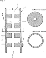
- Fig. 1 is a schematic sectional view of a basic embodiment of a tubular reaction vessel according to the present invention. ( Fig. 1 is a vertical sectional view of the tubular reaction vessel.)
- the numeral 1 denotes a tubular reaction vessel
- 2 denotes a silicon deposition feedstock gas inflow opening
- 3 denotes a deposited silicon discharge opening
- 4 denotes a flow resistance-increasing region
- 5 denotes a space through which the silicon deposition feedstock gas is passed.
- the tubular reaction vessel 1 shown in Fig. 1 has the silicon deposition feedstock gas inflow opening 2 and the deposited silicon discharge opening 3, and is provided with the flow resistance-increasing regions 4 on a wall surface with which the feedstock gas is contacted.
- the section along the line A-A' is of an area formed with the flow resistance-increasing region at a right angle to the longitudinal direction; the section along the line B-B' is of an area without the flow resistance-increasing region.
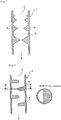
- Fig. 2 is a schematic sectional view showing another embodiment of the tubular reaction vessel according to the present invention.
- the numerals in Fig. 2 indicate the same items as in Fig. 1 .
- the flow resistance-increasing regions shown in Fig. 1 are ring-shaped protrusions triangular in cross section, provided on the internal wall of the tubular reaction vessel (hereinbelow, the ring-shaped protrusions on the internal wall of the tubular reaction vessel will be referred to as orifices) .
- the orifices rectangular in cross section are provided on the internal wall.
- a plurality of flow resistance-increasing regions 4 will be suitably provided depending on the size of the tubular reaction vessel.
- the intervals at which the flow resistance-increasing regions are provided may be regular as shown in Figs. 1 and 2 , or may be specifically determined irregular intervals.
- the orifice height is represented by H, the skirt width by Q, and the orifice interval by P. A detailed description will be given below.
- the tubular reaction vessel 1 comprises a longitudinally-extending wall with a space thereinside.
- the reaction vessel has a silicon deposition feedstock gas inflow opening and a deposited silicon discharge opening at an upper portion and a lower end portion respectively, and further has a flow resistance-increasing region on a wall surface to be contacted with the feedstock gas.
- the shape of the reaction vessel is not particularly limited provided that a silicon deposition feedstock gas is supplied through the upper silicon deposition feedstock gas inflow opening 2, that silicon is deposited and molten on a heated surface of the reaction vessel wall (a) facing a space 5, and that an opening (discharge opening 3) is formed at a lower end portion for allowing silicon to drip down by gravity from the vessel.
- the cross-sectional shape of the tubular reaction vessel 1 is not particularly limited.
- the transverse cross section (along the line B-B') of the space 5 is basically circular as shown in Fig. 1 or 2 , and may be any shapes such as polygonal shapes including triangular and square shapes.
- the transverse cross section of the space 5 may be slit-shaped as illustrated in Fig. 13 .
- the slit shapes in transverse cross section of the space 5 of the reaction vessel 1 include the rectangular shape as shown in Fig. 13 and, although not shown, corner-rounded polygonal shape, elliptical shape, C-shaped curved rectangular shape, rhomboid shape, one side open square box shape( ⁇ shape), L shape, T shape, cross shape, star shape, S shape and scroll shape.
- a further example of the slit shapes is a continuous circular slit shape as shown in Fig. 14 .
- reaction vessel of the invention is a scale-up property. That is, the reaction vessel of the invention can be scaled up from a laboratory-scale small vessel to a substantially analogous but industrial large-scale vessel, so as to provide reaction results surprisingly similar to laboratory results.
- the reaction vessel may be produced by know molding methods.
- the reaction vessel may consist of an integral body, or two or more parts joined together.
- a large-scale reaction vessel for industrial use is preferably constructed by connecting structural parts of the tubular reaction vessel, each of which is 1.5 m long at maximum, to obtain as uniform mechanical properties as possible of the tubular reaction vessel material. Connection of the parts may be flange connection.
- the tubular reaction vessels are ditched to create a screw, and are connected together by means of the screws. In the case of the screw connection, it is preferred that the inner surface of the tubular reaction vessel is free from steps. When steps are present, silicon is locally deposited thereon from which breakage of the reaction vessel possibly takes place.
- the diameter D of the tubular reaction vessel is not particularly limited and may be selected appropriately depending on the silicon production scale, within production conditions of the structural material.
- the length L of the reaction vessel may be extended as required by screw connecting reaction vessel parts.
- the length to diameter ratio (L/D) of the tubular reaction vessel although variable depending on arrangement of the flow resistance-increasing regions, is in the range of 1 to 30, and preferably 3 to 20 in order to achieve a sufficient reaction rate of the feedstock gas and a good silicon yield.
- the diameter D of the tubular reaction vessel may be constant at any points as shown in Figs. 1 to 16 . It is also possible, although not shown, that the diameters differ from place to place. In the case of the slit shape, the width may be constant or varied relative to the longitudinal direction (direction L) of the reaction vessel.
- the thickness of the tubular reaction vessel is not particularly limited, and will be such that the reaction vessel will have strength enough to support its own weight. That is, the thickness does not need to be unnecessarily large and will suitably range from 5 to 100 mm, and preferably from 10 to 50 mm.
- the silicon discharge opening 3 of the reaction vessel 1 may have a horizontal peripheral edge. It is also appropriate that the peripheral edge is sloped or waved. In a preferred embodiment, the discharge opening 3 is tapered, with the thickness being gradually reduced toward the tip, so that the silicon melt can drip down clear from the discharge opening 3.
- the tubular reaction vessel 1 is heated to above the melting point of silicon and the inside of the vessel is contacted with chlorosilane and the silicon melt.
- the vessel is preferably made of a material highly resistant to these temperature conditions and contact.
- Such materials include single and composite materials of carbon materials such as graphite, pyrolytic carbon and carbon fiber-reinforced carbon composite materials, and ceramic materials such as silicon carbide (SiC), silicon nitride (Si3N4), boron nitride (BN) and aluminum nitride (AlN).
- carbon materials such as graphite, pyrolytic carbon and carbon fiber-reinforced carbon composite materials
- ceramic materials such as silicon carbide (SiC), silicon nitride (Si3N4), boron nitride (BN) and aluminum nitride (AlN).
- isotropic graphite is preferable to constitute the wall (a) of the reaction vessel.
- the vessel is preferably coated with pyrolytic carbon, Si3N4 or SiC at least in the area that is contacted with the silicon melt.
- the flow resistance-increasing regions are provided to effectively diminish the upward flow which is a layer inhibiting diffusion in the tubular reaction vessel and to effectively mix the feedstock gas in the vicinity of the vessel central axis with the upward flow.
- the provision of the flow resistance-increasing regions achieves both improved reaction rate of the feedstock gas and by-products prevention.
- the feedstock gas reaction rate is defined as a conversion ratio of the feedstock gas relative to any substance converted therefrom while the feedstock gas is supplied into the space 5 of the tubular reaction vessel 1 and is discharged from the space 5.
- the silicon yield mentioned later is defined as a conversion ratio of any substance converted from the feedstock gas, relative to the silicon produced.
- the flow resistance-increasing regions 4 may each be a protrusion, a concave or a slope, as described below.
- Protrusion is the most preferable embodiment of the flow resistance-increasing region.
- the protrusion means a raised portion of the tubular reaction vessel wall protrudent toward the space 5.
- the protrusion is a ring-shaped protrusion (orifice) circulating on the internal wall of the tubular reaction vessel, as illustrated in the cross section along the line A-A'.
- the protrusion will be described in detail hereinbelow based on this typical embodiment orifice.
- the cross sectional shape of the orifice in a vertical direction is not particularly limited.
- the orifice in cross section may be triangle as illustrated in Fig. 1 , rectangle (oblong) as illustrated in Fig. 2 , polygon (not shown), or a top-curved protrusion (not shown).
- the orifice has a cross sectional shape such that gas stagnation will be less and the silicon melt will flow down smoothly.
- the orifice is more preferably triangle in cross section as illustrated in Fig. 1 because the flow will be difficult when the protrusion has corners.
- the triangular orifice may have a regular shape such as right-angled triangle or isosceles triangle, or may have an irregular triangle shape.
- the flow resistance-increasing region has a triangular cross section that is sloped more gently in the downstream gas flow side than in the upstream side. That is, as shown in Fig.
- the exterior angle of the triangle and the wall surface is desirably more obtuse in the downstream side of the gas flow than in the upstream side.
- the contact point is more preferably curved as shown in Fig. 3 , with designation R (partially semicircle) in accordance with JIS, so that the silicon melt having a high surface tension can flow down more smoothly.
- R is preferably in the range of about 5 to 10.
- the orifice opening through which the gas is passed may be circular as shown in Figs. 1 and 2 or, although not shown, elliptical or polygonal.
- the orifice opening through which the gas is passed is preferably positioned exactly in the center of the tubular reaction vessel 1 as shown in Figs. 1 and 2 . Namely, the center of the orifice opening preferably meets the central axis of the gas passageway of the tubular reaction vessel.
- an eccentric opening may be employable. The eccentric opening may cause nonuniform heating, and therefore the opening is desirably positioned on the central axis of the gas passageway.
- the orifice blocks part of the gas passageway, so that the gas flow is locally accelerated. As a result, the occurrence of the upward flow is prevented and the feedstock gas can be efficiently mixed with the upward flow in the downstream of the orifice.
- the protrusion height H from the tubular reaction vessel internal wall to the orifice tip will be preferably such that the area in which the gas passageway is blocked by the protrusion is 10 to 95%, more preferably 30 to 95%, and optimally 50 to 95% of the cross sectional area of the tubular reaction vessel 1 in the wall provided with the protrusion.
- the upward flow being a layer inhibiting diffusion of the feedstock gas can be effectively reduced and the feedstock gas in the vicinity of the tubular reaction vessel central axis can be effectively mixed with the upward flow.
- the reaction efficiency of the feedstock gas can be improved and the by-products can be prevented.
- the orifice skirt width Q (shown in Figs. 1 and 2 ) is preferably 50 to 600%, and more preferably 100 to 400% relative to the protrusion height H. Too large a skirt width Q reduces the effect of the protrusion, and too small a skirt width possibly leads to lowered protrusion strength.
- the number of orifices to be provided is determined appropriately depending on the size of the tubular reaction vessel, the flow speed and rate of the feedstock gas, and desired reaction results. A plurality of orifices are provided. In an optimum embodiment, the number of orifices ranges from 3 to 10.
- the plurality of orifices are preferably provided at intervals P that are 100 to 500%, and more preferably 200 to 400% relative to the inner diameter D of the tubular reaction vessel 1.
- the intervals P are too small, the protrusions will not produce sufficient effects. Too large intervals reduce the probability that the gas will contact with the wall surface.
- the orifices are triangular or curved in cross section, the interval P is a distance between peaks of the height H as shown in Fig. 2 .
- the interval P is a distance between central points of the flat areas as shown in Fig. 1 .
- the protrusion height H, skirt width Q and intervals P are regular as illustrated in Figs. 1 and 2 .
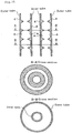
- the skirt width Q alone is changed as shown in Fig. 4 , in which the more downstream of the gas passageway the protrusion, the greater the skirt width Q.
- the embodiment of Fig. 4 may be turned upside down so that the skirt width Q narrows toward the downstream of the gas passageway.
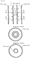
- the protrusion height H may be changed (be sequentially increased) as shown in Fig. 5 .
- the embodiment of Fig. 5 may be turned upside down (so that H is sequentially decreased).
- the intervals P alone may be changed as shown in Fig. 6 .
- the embodiment of Fig. 6 may be turned upside down.
- various embodiments of the protrusion height H, skirt width Q and interval P may be arbitrarily combined.
- the protrusion height H, the skirt width Q and the intervals P may be gradually increased as shown in Fig. 7 .
- the heating energy from heating means tends to be concentrated to the orifice-provided regions, and therefore the internal temperature is often raised, possibly resulting in breakage of the tubular reaction vessel. Accordingly, it is desirable that the thickness of the reaction vessel is reduced by concaving the external wall in the orifice-provided region to prevent overheating.
- the external wall is desirably concaved semicircularly as shown in Fig. 26 .
- the concave depth is not particularly limited.
- the external wall may be concaved to a depth such that the distance from the bottom of the semicircular concave to the orifice top is equal to the thickness of the tubular reaction vessel. There is no problem if the concave depth is smaller.
- the concave may be semi-spindle shaped so as to reduce the thickness of the reaction vessel wall near the lower surface of the orifice because heat is most often concentrated to the orifice's lower surface to overheat the area. The reduction thickness of the reaction vessel wall from the external wall prevents heat from being concentrated to the orifice, so that the overheating the inside of the orifice can be prevented, leading to enhanced durability of the tubular reaction vessel.
- the aforementioned various provision embodiments will be appropriately selected and adjusted such that the silicon deposition efficiency will be most enhanced depending on the reaction vessel diameter or the gas feeding rate.
- a gas heating process in the tubular reaction vessel 1 may be designed arbitrarily by appropriately selecting and adjusting the aforesaid provision embodiments of the flow resistance-increasing regions. Namely, the present invention achieves the following:
- the reaction vessel that is circumferentially continuous circular slit in horizontal cross section consists of an outer tube and an inner tube.
- the flow resistance-increasing regions may be favorably provided on both the external wall of the inner tube and the internal wall of the outer tube as shown in Fig. 15 ; or may be formed only on the external wall of the inner tube as shown in Fig. 16 ; or, although not shown, may be formed only on the internal wall of the outer tube.
- protrusions that do not circulate on the internal wall may be provided as illustrated in Figs. 8 and 9 .
- the protrusions having these shapes are capable of the same effects as those shown in Fig. 1 .
- the protrusions may be inclined like gas turbine blades to swirl the stream of the silicon deposition feedstock gas in the reaction vessel, or to arbitrarily combine clockwise and counterclockwise swirls to achieve higher degree of mixing.
- the protrusion cross sectional shape, height H, width Q, protrusion number and interval P may be determined similarly to the orifice embodiments.
- the material of which the protrusions are composed may be arbitrarily selected from the materials of the reaction vessel, which is favorable to reduce the contamination of the deposited silicon with impurities. More favorably, the protrusions and the reaction vessel 1 are made of materials having similar characteristics.
- the orifices are preferable in the present invention, and the vertical cross section of the protrusion is preferably triangular in view of drip down of the silicon melt. Further preferably, the opening of the protrusion will center align with the reaction vessel, in which case the feedstock gas can be uniformly heated anywhere in the reaction vessel.
- the concave indicates a depressed area on the internal wall surface.
- the concave cannot be deeper than the thickness of the reaction vessel 1, nevertheless, the effect obtained per concave may be smaller than achieved per protrusion, but the concaves do have a function to reduce the upward flow that inhibits diffusion of the feedstock gas onto the deposition surface and to mix the feedstock gas in the vicinity of the reaction vessel central axis with the upward flow.
- the cross sectional shapes of the concave may be substantially the same as the orifices and the baffle plates, except that the protrusions are recessed. Specific examples are shown in Figs. 10 and 11 .
- the concave depth H and, the frontage width Q correspond to the protrusion depth H and the skirt width Q respectively.
- the depth H and the frontage width Q desirably have a relation such that Q/H is in the range of 0.5 to 5, and preferably 1 to 3.
- the depth H cannot be larger than the thickness of the reaction vessel 1.
- a higher effect can be achieved as the intervals P become smaller.
- a preferred embodiment of the concaves is such that the concaves are arranged on the entire deposition surface like dimples on a golf ball.
- the tubular reaction vessel in part or entirely forms a flow resistance-increasing region.
- the slope is not particularly limited as long as the flow direction of the silicon deposition gas can be changed.
- An example is a meander shape as shown in Fig. 12 . Although not shown, the meander may be spiral.
- the slope may be a continual curve in the tubular reaction vessel or may be a combination of linear and curved parts.
- the aforesaid protrusions and concaves may be provided in arbitrary combination. Further, the size (height, depth, width, spiral sharpness) and provision number and interval may be determined arbitrarily and may be combined arbitrarily.
- the silicon production process according to the present invention employs the above-described tubular reaction vessel. According to the method, a silicon deposition feedstock gas containing a silane is introduced through the silicon deposition feedstock gas inflow opening, and polycrystalline silicon is produced from the silane-containing silicon deposition feedstock gas in the heated reaction vessel.
- the silanes include known silanes used as silicon material gases. Specific examples include monosilane, trichlorosilane (TCS), silicon tetrachloride (STC), monochlorosilane and dichlorosilane. Of these, monosilane and TCS are preferable because highly pure products meeting industrial needs are easily available in large quantities. Further, it is most preferable that the feedstock gas is based on TCS that causes little silicon fine powder.
- the feedstock gas may be diluted prior to use.
- the diluting gas is preferably one that does not adversary affects the silicon production. Particularly, when the unreacted feedstock gas is circulated for use, the diluting gas is preferably based on hydrogen.
- the feedstock gas will be preferably diluted such that the feedstock gas constitutes 1 to 30 mol%, and more preferably 3 to 20 mol% of the diluted gas.
- the feedstock gas may be diluted beforehand and supplied from the feedstock gas supply tube. It is also possible that the diluting gas is supplied to the reaction vessel through a respective supply tube separately from the feedstock gas.
- the pressure at which the feedstock gas is reacted is not particularly limited as long as industrial production is feasible and stable yield is ensured.
- the pressure may range from atmospheric pressure to 3 MPaG, and preferably from atmospheric pressure to 1 MPaG.
- the dwell times of the gases in a predetermined-volume reaction vessel may be adjusted appropriately depending on reaction conditions such as temperature and pressure.
- the average dwell time will range from 0.001 to 60 seconds, preferably from 0.01 to 10 seconds, and more preferably from 0.05 to 1 second.
- the dwell time in this range permits a sufficiently efficient reaction rate of the feedstock gas while achieving higher effects of the flow resistance-increasing regions.
- Conditions of the silicon production in the present invention are not particularly limited as long as the aforesaid tubular reaction vessel is used.
- the reaction conditions such as the tubular reaction vessel size, reaction vessel structure such as configuration of the flow resistance-increasing regions, feed ratio of the silane to hydrogen, gas feed rate, deposition surface temperature and operation pressure, are preferably manipulated such that the silane-containing feedstock gas supplied into the production apparatus will be reacted to achieve a silane reaction rate of at least 25%, and preferably at least 30%.
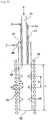
- Fig. 17 is a schematic sectional view of a silicon production reaction apparatus using the tubular reaction vessel according to the present invention.
- the silicon production reaction apparatus has a structure such that a silicon deposition feedstock gas A is passed through a space 24 enclosed by a wall (a) extending in a vertical direction to constitute a reaction vessel 21, silicon is deposited and molten on a heated surface of the wall (a) facing the space 24, and the silicon melt is allowed to drip down through an opening (deposited silicon discharge opening) 22 at a lower end.
- heating means 23 is arranged so as to surround the external wall of the reaction vessel.
- the heating means 23 of the silicon production reaction apparatus may be known heating means without limitation as long as it is capable of heating the surface of the wall (a) facing the space 24 above the melting point of silicon.
- the melting point of silicon is generally considered to be in the range of 1410 to 1430°C.
- the heating means may be a type capable of heating the surface of the wall (a) facing the space 24 by means of external energy.
- Examples of such heating means include high-frequency heating means such as high-frequency heating coils, heating wire means, and infrared heating means.
- the present invention optimally employs a high-frequency heating device capable of efficient heating of the reaction vessel with less energy, alternatively it is also possible to use different types of heating means in combination.
- the heating means 23 may be controlled by single temperature control means in the whole range of a silicon deposition reaction section I. Alternatively, the heating means 23 may be divided into two parts, namely upper and lower parts, or more parts and each part may be temperature controlled separately.
- the heating means is arranged per at least one zone and each heating means is controlled to supply optimum heat energy depending on the heat removed by the reaction gas between the protrusions.
- a tubular reaction vessel as described hereinabove may be employed in which the thickness of the reaction vessel outside the protrusion is reduced by concaving the external wall.
- the heating means is arranged such that the heating value in the protrusion-provided areas is smaller than the rest. For example, this can be achieved by increasing the distance from the external wall of the protrusion-provided areas to the heating coil relative to the other areas (namely, protrusion-free areas), or by arranging the heating coil other than near the protrusion-provided areas.
- a shield against the high frequency wave is arranged on the external wall of the protrusion-provided areas to reduce transmission of the high frequency wave.
- the shield against the high frequency wave can be achieved by inserting copper plates to reduce the high frequency energy to the areas, so that the overheating at the protruded areas may be prevented.
- the embodiment of reducing the thickness of the reaction vessel wall and the embodiment of reducing the high frequency energy from the high frequency heating coil may be performed individually or in combination.
- a heat insulator is desirably interposed between the wall (a) and the heating means 23 to enhance the heating energy efficiency.
- a further heat insulator is preferably arranged around the outer periphery of the heating means 23.
- the feedstock gas is supplied through a feedstock gas supply tube 25.
- the feedstock gas supply tube 25 is preferably equipped with cooling means 27 to prevent decomposition of the silanes when the supply tube is heated by the heat transferred through conduction from the reaction vessel 21 or the heat transferred through radiation.
- the cooling means 27 preferably cools the internal wall of the feedstock gas supply tube 25 to a temperature at which the feedstock gas supplied will not self-decompose, namely, to about 500°C or below. Further, it is preferable for reducing thermal load neat the inflow opening of the reaction section I that the feedstock gas is preheated and the cooling means 27 is adopted such that the feedstock gas supplied will have a temperature of 100 to 500°C, and preferably 200 to 400°C.
- FIG. 17 A specific embodiment of the cooling means 27 is shown in Fig. 17 , in which a jacket is arranged around the feedstock supply tube 25 and a refrigerant is circulated in the jacket from D1 to D2, this embodiment is simple and preferable. Suitable refrigerants include water, heat transfer oil, steam and gases.
- the feedstock gas supply tube 25 may be a multiring nozzle and a diluting gas may be used as a refrigerant. It is also appropriate to arrange a radiator plate around the feedstock gas supply tube 25.
- the material of the feedstock gas supply tube 25 may be the same as the vertically extending wall (a) described later, or may be iron or stainless steel.
- the silicon deposition feedstock gas supplied from the feedstock gas supply tube 25 is reacted to deposit silicon in the reaction section I of the reaction vessel 21.
- the inner surface of the wall (a) in the reaction section I may be temperature controlled to at least the melting point of silicon to cause the silicon melt to continually drip down.
- the surface is temperature controlled to a temperature blow the silicon melting point at which deposition of silicon is feasible, solid silicon is temporarily deposited, and the surface temperature is increased to at least the silicon melting point to melt and drip down part of or all the deposited silicon.
- the temperature may be locally in excess of the melting point of silicon.
- Silicon is generally deposited on a surface having a temperature of 600°C or above.
- the surface temperature is preferably 1100°C or above, more preferably 1250°C or above, and optimally 1300°C or above.
- the upper limit of the silicon deposition temperature is preferably 1700°C, and more preferably 1600°C.
- the tubular reaction vessel of the invention provides a turbulent gas flow because of the flow resistance-increasing regions, and the average gas temperature can be uniformly increased.
- the average gas temperature per unit quantity of the gas discharged from the tubular reaction vessel is desirably 700°C or above, preferably 800 to 1500°C, and more preferably 900 to 1400°C.
- This gas temperature may be achieved by employing the aforesaid structure of the tubular reaction vessel and silicon production conditions according to the present invention, leading to effective production of silicon. Without the flow resistance-increasing regions such as protrusions, uniform heating is impossible and an increased proportion of the feedstock is passed without being heated, so that the average gas temperature is lowered to about 600°C.
- the temporarily deposited solid silicon may be molten and dropped for recovery by increasing the output of the heating means 23 and/or lowering the gas feed rate to raise the wall surface temperature, these methods may be performed singly or in combination.
- the wall (a) of the reaction vessel 21 is heated such that at least part of the surface including a lower end portion is heated to the silicon melting point or above.
- the heating area preferably ranges from the lower end to 20% or more, and preferably 30% or more of the total length.
- the heating area preferably ranges from the lower end to 90% or less, and preferably 80% or less of the total length. In the case where a feedstock gas outlet opening 26 is positioned above the uppermost part of the heating means 23 as shown in Fig. 17 , the heating area will range from the uppermost part of the heating means 23 to a length along the reaction section I.
- reaction section is preferably divided into two parts as shown in Fig. 18 , in this case, a principal (deposition) reaction section IA for essentially depositing silicon and heating means 23A for the principal reaction section IA are arranged, and an auxiliary reaction section IB for silicon deposition attributed to the conducted heat above the principal reaction section and heating means 23B for the auxiliary reaction section are arranged.
- a principal (deposition) reaction section IA for essentially depositing silicon and heating means 23A for the principal reaction section IA
- auxiliary reaction section IB for silicon deposition attributed to the conducted heat above the principal reaction section and heating means 23B for the auxiliary reaction section are arranged.
- the heating means 23A and the heating means 23B in Fig. 18 are adopted to be output controlled separately.
- the heating means 23A for the principal reaction section IA is mainly used to heat the reaction vessel 21, on the other hand, the heating means 23B for the auxiliary deposition section IB is usually power controlled to zero or a small output.
- the temperature of the wall surface of the auxiliary reaction section IB is raised by the heat transferred through conduction from the heating means 23A, and the silicon deposition temperature is reached locally and a small amount of silicon is possibly deposited. Therefore, the output of the heating means 23B is sometimes increased so that the silicon deposited in the auxiliary reaction section IB is molten and dropped. By this means, silicon scaling can be prevented stably over a long term.
- respective flow resistance-increasing regions 24A and 24B are preferably arranged in the reaction sections.
- the flow resistance-increasing region 42B provided in the auxiliary reaction section IB increases the contact efficiency of the feedstock gas with the reaction vessel wall, prevents the heat transferred through conduction from the heating means 23A from transferring endlessly upward in the reaction vessel, and restricts the silicon deposition section to within the auxiliary reaction section IB. As a result, the heat energy otherwise lost in the upper part can be recovered maximally and silicon scaling growth can be prevented further effectively.
- a method may be adopted in which an etching gas such as hydrogen chloride is intermittently supplied to remove the attached scales. These methods may be performed in combination.
- Fig. 19 shows an embodiment in which the feedstock gas outlet opening 26 is at a position equal to or lower than the upper end of the heating means 23.
- the silicon deposition feedstock gas can flow round into a space between the vertically extending wall (a) and the feedstock gas supply tube 25.
- a seal gas (seal gas C, seal gas supply tube 28) is preferably supplied to this low temperature region.
- the seal gas is suitably one not detrimental to the silicon production.
- Suitable examples of the seal gases include inert gases such as argon and helium, and hydrogen and nitrogen.
- the seal gas is appropriately mixed with a gas capable of etching the silicon, for example hydrogen chloride.
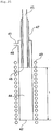
- Fig. 20 is a schematic sectional view of a silicon production reaction apparatus for use in the invention, in which the tubular reaction vessel has a double ring structure.
- the reaction vessel has a structure such that the feedstock gas is passed through a space 24 created between an internal wall (a) of an outer tube 21a and an external wall (a') of an inner tube 21a', silicon is deposited and molten on a heated surface facing the space 24, and the silicon melt is allowed to drip down through a lower end opening 22.
- Heating means 23A such as high frequency heating means is arranged around the outer periphery of the outer tube.
- the ring-shaped reaction vessel shown in Fig. 20 may be provided with auxiliary heating means 23C inside the inner tube for sufficiently heating the surface of the inward wall (a') facing the space 24. (The provision of the heating means 23C is not always necessary.)
- the heating means 23C may be similar to the heating means 23A using a high frequency wave or the like, or may be such heating means that uses a heating wire or infrared ray.
- the outward wall (a) is made of a thin carbon material having a thickness of about 10 mm and the inward wall (a') is made of a thick carbon material having a thickness of at least 20 mm.
- the space-facing surfaces of the outward and inward walls (a) and (a') can be effectively heated together with only the outward heating means 23A such as high frequency heating means.
- the outward wall (a) may comprise a carbon fiber-reinforced carbon composite material.
- a plurality of the tubular reaction vessels are aligned and the heating means such as high frequency heating means is arranged so as to surround the outer periphery of the grouped reaction vessels with a spacing from each of the reaction vessels.
- the heating means such as high frequency heating means is arranged so as to surround the outer periphery of the grouped reaction vessels with a spacing from each of the reaction vessels.
- reaction vessels 112 are aligned in a horizontal direction and a high frequency heating coil 113 is wound along the outer periphery of the reaction vessels grouped in line (within a dashed line) 112a.
- the arrangement of a plurality of the reaction vessels is not particularly limited to the linear alignment as shown in Fig. 27 , and two-line arrangement and cyclic arrangement are possible as long as the reaction vessels are arranged in a horizontal direction along the inner periphery of the high frequency heating means, however, for effective heating with a high frequency wave from the high frequency heating means, at least part of the tube walls of the reaction vessels will be adjacent to the inner peripheral surface of the high frequency heating means.
- the structure of the silicon production reaction apparatus used in the invention is not particularly limited to the aforementioned, and other known structures as described in JP-A-2002-29726 may be adopted without limitation.
- the illustrated reaction vessel 21 is provided in a closed vessel 30 connected with an exhaust gas outlet tube 29 for an exhaust gas G. Because this reaction vessel is isolated from the outside air, silicon can be obtained in high purity and the exhaust gas can be recovered effectively.
- the closed vessel 30 may be provided with a cooling chamber in a lower part. The cooling chamber forms a room in which silicon 35 dropped down from the reaction vessel 21 is collected.
- the closed vessel 30 may be further provided with, in addition to the exhaust gas outlet tube 29, cooling jackets 33 through which refrigerants are circulated from F 1 to F 2 and from F 3 to F 4 , and a cold space 34 cooled by the jackets.
- the lower cooling chamber may be provided with a cooling gas supply tube 32 though which a cooling gas H is supplied for cooling the silicon 35.
- a partition plate 36 may be provided in the cold space 34 to permit recovery of the silicon 35 from a recovery opening 37.
- a plurality of the partition plates 36 will be provided to improve safety in the silicon recovery.
- a tubular reaction vessel 41 made of general-purpose isotropic graphite was provided, which was cylindrical and straight in a longitudinal direction and had an inner diameter of 150 mm, a reaction section length I of 600 mm and a thickness of 15 mm.
- Heating means 43 was a high frequency heating system.
- the high frequency heating coil as the heating means 43 for the reaction section I extended along the reaction section I of the tubular reaction vessel 41 to a length of 100 mm from each of the upper and lower ends of the reaction section I.
- the frequency of the high frequency heating means was 8 kHz.
- a 50 mm thick carbon fiber heat insulator was arranged between the reaction vessel 41 and the heating means 43, extending from 30 mm above the lower end of the reaction vessel 41 to the upper end of the heating means 43.
- Flow resistance-increasing regions provided inside the tubular reaction vessel 41 were ring-shaped protrusions (orifices) on the internal wall of the reaction vessel, were triangular in cross section and were made of the same material as the reaction vessel.
- the protrusion height H was 60 mm
- the protrusion skirt width Q was 30 mm
- the protrusion interval P was 125 mm.
- the protrusions were provided at three points on the internal wall of the reaction vessel 41.
- a feedstock gas supply tube 45 was equipped with a cooling mechanism of water cooling jacket system.
- a feedstock gas inflow opening 46 was a circular opening 40 mm in inner diameter. The feedstock gas inflow opening 46 was at a position 100 mm below the upper end of the heating means 43, so that the distance from the inflow opening 46 of the feedstock supply tube 45 to a deposited silicon discharge opening 42 at a lower end of the reaction vessel 41 became equal to the length I of the reaction section.
- a gas mixture was supplied through the feedstock gas supply tube 45 at rates of 35 kg/h for trichlorosilane and 100 Nm 3 /h for hydrogen, while water was passed through cooling means 47 of the feedstock gas supply tube 45, hydrogen was supplied through a seal gas supply tube 48 at a rate of 5 Nm 3 /h, and the temperature of the internal wall surface of the reaction vessel 41 was raised to and maintained at 1300 to 1400°C by the heating means 43.
- the reaction pressure was about 50 kPaG.
- the composition of the reaction exhaust gas was analyzed by gas chromatography, resulting in a trichlorosilane reaction rate of about 43% and a silicon deposition rate of about 1.5 kg/h. After the deposition reaction had been performed for 2 hours, the supply of trichlorosilane was terminated and the hydrogen feed rate was halved, while the heating output was increased by 20%. As a result, the silicon deposited was molten and dropped down in about 15 minutes. The silicon collected in a reservoir below the reaction vessel weighed approximately 3 kg. The total amount of silicon fine powder and silane oligomer generated was very small, less than 0.5% relative to the silicon.
- a tubular reaction vessel 51 was a vessel with a ring-shaped cross section that consisted of an outer tube 51 (a) and an inner tube 51(a') having a smaller inner diameter.
- the outer tube 51 (a) was an isotropic graphite cylinder 250 mm in inner diameter and 5 mm in thickness.
- the inner tube 51(a') was a general-purpose isotropic graphite cylinder having an inner diameter of 200 mm and a thickness of 15 mm.
- the reaction vessel had a straight reaction section having a length I of 1 m, and an opening 52 at a lower end.
- a space 54 was created between the outer tube 51 (a) and the inner tube 51(a').
- a heating coil capable of generating a high frequency wave of 1 kHz was arranged as heating means 53 to heat part of the space-facing surfaces with which the feedstock gas could contact, to at least the melting point of silicon.
- the heating coil was arranged so as to enclose the outer tube 51 (a) over a range from 0. 15 m below the upper end to 0.1 m below the lower end of the outer tube 51(a).
- a 50 mm thick carbon fiber heat insulator was arranged between the outer tube 51 (a) and the heating coil, extending from the upper end to 0.03 m below the lower end of the outer tube 51(a), and another similar heat insulator was arranged above an upper lid of the inner tube 51(a').
- Flow resistance-increasing regions 58 were provided only on the peripheral surface of the external wall of the inner tube 51(a').
- the flow resistance-increasing regions 58 on the external wall of the inner tube 51(a') were ring-shaped protrusions made of isotropic carbon. They were triangular in vertical cross section and had a height H of 12 mm from the wall surface of the inner tube 51(a'), and a skirt width Q of 20 mm.
- the protrusions were provided in four positions at intervals P of 250 mm.
- a feedstock gas supply tube 55 was made of stainless steel and had a liquid-flow jacket structure as cooling means 57.
- the feedstock gas supply tube was arranged so as to cover the entire upper part of the outer tube 51(a) of the reaction vessel.
- the upper end of the inner tube 51(a') was covered with a lid of the same material as the reaction vessel, so that a feedstock gas inflow opening 56 was created at the uppermost space between the outer tube 51 (a) and the inner tube 51(a').
- the feedstock gas supply tube 55 was cooled by passing water, and the outer tube 51 (a) and the inner tube 51(a') were heated by the high frequency heating means 53 to a temperature of 1300 to 1400°C
- a gas mixture was supplied through the feedstock gas supply tube 55 at rates of 175 kg/h for trichlorosilane and 500 Nm 3 /h for hydrogen.
- the reaction pressure was about 50 kPaG.
- the composition of the reaction exhaust gas was analyzed by gas chromatography, resulting in a silicon deposition rate of 9.5 kg/h and a trichlorosilane reaction rate of about 55%.
- the supply of trichlorosilane was terminated and the hydrogen feed rate was halved, while the heating output was increased by 20%.
- the silicon deposited was molten and dropped down in about 15 minutes.
- the silicon collected in a reservoir below the reaction vessel weighed approximately 19 kg.
- the total amount of silicon fine powder and silane oligomer generated was very small, less than 0.5% relative to the silicon.
- a tubular reaction vessel 41 made of general-purpose isotropic graphite was provided, which was cylindrical and had an inner diameter of 210 mm, a thickness of 25 mm and a length of 4000 mm.
- the reaction vessel 41 included two parts: a principal reaction section IA ranging from the lower end of the reaction vessel to a height of 2800 mm, and an auxiliary reaction section IB having a length of 560 mm above the principal reaction section IA.
- Heating means used herein were high frequency heating systems.
- a high frequency heating coil 43A as the heating means for the principal reaction section IA extended from the upper end of the principal reaction section IA to 50 mm below the lower end of the reaction vessel 41.
- a high frequency heating coil 43B as the heating means for the auxiliary reaction section IB extended to the same height and in the same length as the auxiliary reaction section IB.
- the frequency of the high frequency heating means was 5 kHz, and each of the heating coils 43A and 43B were separately output adjustable.
- a 50 mm thick carbon fiber heat insulator was arranged between the reaction vessel 41 and the heating means 43A and 43B, extending from 30 mm above the lower end of the reaction vessel 41 to the upper end of the reaction vessel 41.
- Flow resistance-increasing regions 49A and 49B provided inside the tubular reaction vessel 41 were ring-shaped protrusions (orifices) on the internal wall of the reaction vessel. They were triangular in cross section and were made of the same material as the reaction vessel.
- the protrusion height H was 70 mm
- the protrusion skirt width Q was 80 mm
- the protrusion interval P was 580 mm.
- the protrusions 49A (principal reaction section) and 49B (auxiliary reaction section) were provided in six points at the regular intervals, starting from the upper end of the auxiliary reaction section IB to the lower end of the principal reaction section IB of the reaction vessel 41.
- a feedstock gas supply tube 45 was a stainless steel tube with an inner diameter of 150 mm and was equipped with a jacket as cooling means 47 in which a 250°C heat transfer oil was circulated.
- the surface of the reaction section IA facing a reaction space 44 was temperature controlled in the range of 1450 to 1500°C while zeroing the output of the heating means 43B and increasing the output of the heating means 43A.
- a gas mixture was supplied into the reaction vessel 41 through the feedstock gas supply tube 45 at rates of 600 kg/h for trichlorosilane and 1000 Nm 3 /h for hydrogen to initiate reaction, and silicon melt started to drip down continually.
- the reaction pressure was about 50 kPaG.
- the reaction exhaust gas was analyzed by gas chromatography to determine its composition, resulting in a trichlorosilane reaction rate of about 52% and a silicon deposition rate of about 19.5 kg/h. That is, the reaction over a period of 144 hours produced about 2500 kg of silicon.
- the total amount of silicon fine powder and silane oligomer generated was very small, less than 0.5% relative to the silicon.
- the silicon deposition reaction was performed in the same manner as described in Example 3, except that the ring-shaped protrusions (orifices) had an outer periphery as shown in Fig. 26 .
- Fig. 26 is an enlarged sectional view of a vicinity of the ring-shaped protrusion.
- an outer peripheral portion of the ring-shaped protrusion (orifice) was concaved to provide a semi-circular ditch 30 mm in radius, and high frequency heating coils were arranged other than near the protrusion-provided area.
- This configuration was adopted for all the ring-shaped protrusions of the tubular reaction vessel used in Example 3, and the other apparatus and reaction conditions were the same as in Example 3.
- the surface temperature of the ring-shaped protrusions was maintained at 1500°C or below, the isotropic carbon of which the tubular reaction vessel was made was substantially free from deterioration, and the silicon produced had a reduced carbon concentration.
- the silicon deposition reaction was performed using the same reaction apparatus (shown in Fig. 22 , the numerals have the same indications) and under the same conditions as in Example 1, except that the reaction vessel 41 had no flow resistance-increasing regions 49 on the internal wall as illustrated in Fig. 25 .
- the reaction resulted in a trichlorosilane reaction rate of 22% and a silicon yield of about 1.6 kg.
- the total amount of silicon fine powder and silane oligomer generated from the reaction was not less than 3% relative to the silicon.
Applications Claiming Priority (2)
| Application Number | Priority Date | Filing Date | Title |
|---|---|---|---|
| JP2003293197 | 2003-08-13 | ||
| PCT/JP2004/011542 WO2005016820A1 (ja) | 2003-08-13 | 2004-08-11 | 管型反応容器および該反応容器を用いたシリコンの製造方法 |
Publications (3)
| Publication Number | Publication Date |
|---|---|
| EP1661857A1 EP1661857A1 (en) | 2006-05-31 |
| EP1661857A4 EP1661857A4 (en) | 2009-07-15 |
| EP1661857B1 true EP1661857B1 (en) | 2016-12-21 |
Family
ID=34190988
Family Applications (1)
| Application Number | Title | Priority Date | Filing Date |
|---|---|---|---|
| EP04771527.1A Expired - Fee Related EP1661857B1 (en) | 2003-08-13 | 2004-08-11 | Tubular reaction vessel and process for producing silicon therewith |
Country Status (7)
| Country | Link |
|---|---|
| US (1) | US7553467B2 (ja) |
| EP (1) | EP1661857B1 (ja) |
| JP (1) | JP5291282B2 (ja) |
| CN (1) | CN100335162C (ja) |
| AU (1) | AU2004265173B2 (ja) |
| CA (1) | CA2535537C (ja) |
| WO (1) | WO2005016820A1 (ja) |
Families Citing this family (26)
| Publication number | Priority date | Publication date | Assignee | Title |
|---|---|---|---|---|
| KR100696501B1 (ko) | 2005-03-23 | 2007-03-19 | 삼성에스디아이 주식회사 | 플라즈마 디스플레이 장치 |
| GB2429143B (en) * | 2005-07-11 | 2008-02-13 | Re18 Ltd | Vessel and source of radio frequency electromagnetic radiation, heating apparatus and method of heating a feedstock |
| DE102006050901A1 (de) * | 2005-11-17 | 2007-05-31 | Solarworld Industries Deutschland Gmbh | Verfahren zum Herstellen eines Halbleiterkörpers und zum Herstellen einer Halbleitervorrichtung |
| KR100813131B1 (ko) * | 2006-06-15 | 2008-03-17 | 한국화학연구원 | 유동층 반응기를 이용한 다결정 실리콘의 지속 가능한제조방법 |
| US8025804B2 (en) | 2006-12-19 | 2011-09-27 | Avi Efraty | Continuous closed-circuit desalination method without containers |
| US20140131911A1 (en) * | 2007-04-25 | 2014-05-15 | Greenly Group For Solar Technologies, Ltd. | Cartridge Reactor for Production of Materials via the Chemical Vapor Deposition Process |
| CN101707871B (zh) * | 2007-04-25 | 2013-06-12 | 卡甘·塞兰 | 通过大表面积气-固或气-液界面及液相再生沉积高纯硅 |
| JP5334490B2 (ja) * | 2008-08-06 | 2013-11-06 | 株式会社トクヤマ | シリコン製造装置 |
| WO2010016133A1 (ja) * | 2008-08-07 | 2010-02-11 | 電気化学工業株式会社 | カーボン製反応装置 |
| CN102639438B (zh) * | 2009-11-25 | 2016-04-13 | 戴纳泰克工程有限公司 | 用于生产硅的反应器和方法 |
| KR101329030B1 (ko) * | 2010-10-01 | 2013-11-13 | 주식회사 실리콘밸류 | 유동층 반응기 |
| CN107675250B (zh) * | 2011-03-28 | 2020-08-07 | 应用材料公司 | 选择性沉积外延锗合金应力源的方法与设备 |
| JP5653857B2 (ja) * | 2011-07-25 | 2015-01-14 | 株式会社トクヤマ | ポリシリコン受け容器 |
| NO334776B1 (no) | 2011-09-26 | 2014-05-26 | Dynatec Engineering As | Reaktor og fremgangsmåte for fremstilling av silisium ved kjemisk dampavsetning |
| JP5995188B2 (ja) * | 2012-05-08 | 2016-09-21 | Jfeエンジニアリング株式会社 | 静止型混合装置及びこれを有するバラスト水処理装置 |
| CN102879362B (zh) * | 2012-09-19 | 2016-03-30 | 有色金属矿产地质调查中心 | 一种用于原子荧光光谱仪气体传输系统的集扩式混匀模块 |
| KR101816339B1 (ko) * | 2014-05-13 | 2018-01-08 | 주식회사 엘지화학 | 연속식 관형반응기를 이용한 클로로실란가스 제조방법 |
| KR101821006B1 (ko) * | 2014-05-13 | 2018-01-22 | 주식회사 엘지화학 | 수평형 반응기를 이용한 폴리실리콘 제조 장치 및 제조 방법 |
| KR101768279B1 (ko) | 2014-09-29 | 2017-08-30 | 주식회사 엘지화학 | 수평형 반응기를 이용한 폴리실리콘 제조 장치 및 제조 방법 |
| GB201505803D0 (en) * | 2015-04-02 | 2015-05-20 | Hanovia Ltd | Conditioning and treating a fluid flow |
| CN105546348A (zh) * | 2015-12-09 | 2016-05-04 | 无锡拓能自动化科技有限公司 | 应用于气体灌装站的高效混合气体灌装管道 |
| CN105546349A (zh) * | 2015-12-09 | 2016-05-04 | 无锡拓能自动化科技有限公司 | 应用于气体灌装站的气体灌装管道 |
| WO2017127925A1 (en) * | 2016-01-26 | 2017-08-03 | Michael Ransom | Apparatus for mixing fluids, including fluids containing solids |
| CN107021606B (zh) * | 2017-04-20 | 2020-01-03 | 江苏太平洋石英股份有限公司 | 连熔法生产光纤用外套管的方法 |
| FR3077511B1 (fr) * | 2018-02-08 | 2022-07-22 | Total Raffinage Chimie | Dispositif d'injection de charge d'une unite fcc. |
| JP7088774B2 (ja) * | 2018-07-31 | 2022-06-21 | 株式会社トクヤマ | シリコン微粒子製造装置 |
Family Cites Families (10)
| Publication number | Priority date | Publication date | Assignee | Title |
|---|---|---|---|---|
| US4374093A (en) * | 1981-02-20 | 1983-02-15 | Mobil Oil Corporation | Continuous-stream upflow zeolite crystallization apparatus |
| US4547258A (en) | 1982-12-22 | 1985-10-15 | Texas Instruments Incorporated | Deposition of silicon at temperatures above its melting point |
| US4710260A (en) | 1982-12-22 | 1987-12-01 | Texas Instruments Incorporated | Deposition of silicon at temperatures above its melting point |
| US5146869A (en) * | 1990-06-11 | 1992-09-15 | National Semiconductor Corporation | Tube and injector for preheating gases in a chemical vapor deposition reactor |
| CA2386382A1 (en) * | 2000-02-18 | 2001-08-23 | G.T. Equipment Technologies, Inc. | Method and apparatus for chemical vapor deposition of polysilicon |
| JP4157281B2 (ja) * | 2000-05-11 | 2008-10-01 | 株式会社トクヤマ | シリコン生成用反応装置 |
| CN100406378C (zh) | 2000-05-11 | 2008-07-30 | 德山株式会社 | 多晶硅的生产装置 |
| DE10048921A1 (de) * | 2000-10-04 | 2002-04-18 | Bosch Gmbh Robert | Vorrichtung zur Bildung eines Reduktionsmittel-Abgas-Gemisches und Abgasreinigungsanlage |
| JP2003002626A (ja) * | 2001-06-18 | 2003-01-08 | Tokuyama Corp | シリコン生成用反応装置 |
| JP4639005B2 (ja) * | 2001-07-03 | 2011-02-23 | 株式会社トクヤマ | シリコンおよびトリクロロシランの製造法 |
-
2004
- 2004-08-11 AU AU2004265173A patent/AU2004265173B2/en not_active Ceased
- 2004-08-11 JP JP2005513164A patent/JP5291282B2/ja not_active Expired - Fee Related
- 2004-08-11 WO PCT/JP2004/011542 patent/WO2005016820A1/ja active Application Filing
- 2004-08-11 US US10/567,943 patent/US7553467B2/en active Active
- 2004-08-11 CN CNB2004800010421A patent/CN100335162C/zh not_active Expired - Fee Related
- 2004-08-11 EP EP04771527.1A patent/EP1661857B1/en not_active Expired - Fee Related
- 2004-08-11 CA CA002535537A patent/CA2535537C/en not_active Expired - Fee Related
Non-Patent Citations (1)
| Title |
|---|
| None * |
Also Published As
| Publication number | Publication date |
|---|---|
| JPWO2005016820A1 (ja) | 2007-10-04 |
| AU2004265173B2 (en) | 2010-05-27 |
| JP5291282B2 (ja) | 2013-09-18 |
| AU2004265173A1 (en) | 2005-02-24 |
| CA2535537C (en) | 2009-10-13 |
| US7553467B2 (en) | 2009-06-30 |
| CA2535537A1 (en) | 2005-02-24 |
| CN100335162C (zh) | 2007-09-05 |
| WO2005016820A1 (ja) | 2005-02-24 |
| US20060219161A1 (en) | 2006-10-05 |
| EP1661857A4 (en) | 2009-07-15 |
| EP1661857A1 (en) | 2006-05-31 |
| CN1735563A (zh) | 2006-02-15 |
Similar Documents
| Publication | Publication Date | Title |
|---|---|---|
| EP1661857B1 (en) | Tubular reaction vessel and process for producing silicon therewith | |
| JP4290647B2 (ja) | シリコン製造用反応装置 | |
| US9764960B2 (en) | Method and apparatus for preparation of granular polysilicon | |
| US7922990B2 (en) | Method and device for producing granulated polycrystalline silicon in a fluidized bed reactor | |
| US6039812A (en) | Device for epitaxially growing objects and method for such a growth | |
| US7029632B1 (en) | Radiation-heated fluidized-bed reactor | |
| US8722141B2 (en) | Process for the continuous production of polycrystalline high-purity silicon granules | |
| US5374413A (en) | Heating of fluidized bed reactor by microwaves | |
| CA2517764C (en) | Silicon production apparatus | |
| CA2576665C (en) | Silicon manufacturing apparatus | |
| US9738530B2 (en) | Polycrystalline silicon deposition method | |
| US20170283266A1 (en) | Poly-silicon manufacturing apparatus and method using high-efficiency hybrid horizontal reactor | |
| JP2003002628A (ja) | シリコン製造装置および製造方法 | |
| EP0931186B1 (en) | A device for epitaxially growing objects and method for such a growth | |
| US10196273B2 (en) | Device for manufacturing polysilicon using horizontal reactor and method for manufacturing same | |
| JP2003020216A (ja) | シリコンの製造方法 | |
| CN201665535U (zh) | 一种用于连续生产液体硅的填料塔 | |
| CN115287760A (zh) | 高温化学气相沉积法生长碳化硅晶体的方法及其装置 | |
| JPS63185017A (ja) | 結晶成長装置 |
Legal Events
| Date | Code | Title | Description |
|---|---|---|---|
| PUAI | Public reference made under article 153(3) epc to a published international application that has entered the european phase |
Free format text: ORIGINAL CODE: 0009012 |
|
| 17P | Request for examination filed |
Effective date: 20060221 |
|
| AK | Designated contracting states |
Kind code of ref document: A1 Designated state(s): DE GB |
|
| DAX | Request for extension of the european patent (deleted) | ||
| RBV | Designated contracting states (corrected) |
Designated state(s): DE GB |
|
| A4 | Supplementary search report drawn up and despatched |
Effective date: 20090612 |
|
| RIC1 | Information provided on ipc code assigned before grant |
Ipc: B01F 5/06 20060101ALI20090605BHEP Ipc: B01J 19/24 20060101ALI20090605BHEP Ipc: B01J 19/00 20060101ALI20090605BHEP Ipc: C01B 33/03 20060101ALI20090605BHEP Ipc: C01B 33/02 20060101AFI20050301BHEP Ipc: B01F 3/02 20060101ALI20090605BHEP |
|
| 17Q | First examination report despatched |
Effective date: 20120224 |
|
| REG | Reference to a national code |
Ref country code: DE Ref legal event code: R079 Ref document number: 602004050538 Country of ref document: DE Free format text: PREVIOUS MAIN CLASS: C01B0033020000 Ipc: C01B0033030000 |
|
| GRAP | Despatch of communication of intention to grant a patent |
Free format text: ORIGINAL CODE: EPIDOSNIGR1 |
|
| RIC1 | Information provided on ipc code assigned before grant |
Ipc: B01J 19/00 20060101ALI20160926BHEP Ipc: B01F 5/06 20060101ALI20160926BHEP Ipc: B01J 19/24 20060101ALI20160926BHEP Ipc: B01F 3/02 20060101ALI20160926BHEP Ipc: C01B 33/03 20060101AFI20160926BHEP |
|
| GRAS | Grant fee paid |
Free format text: ORIGINAL CODE: EPIDOSNIGR3 |
|
| GRAA | (expected) grant |
Free format text: ORIGINAL CODE: 0009210 |
|
| INTG | Intention to grant announced |
Effective date: 20161024 |
|
| RIN1 | Information on inventor provided before grant (corrected) |
Inventor name: NAKAMURA, YASUO Inventor name: WAKAMATSU, SATORU Inventor name: SUGIMURA, SHIGEKI Inventor name: TSUJIO, KENICHI |
|
| AK | Designated contracting states |
Kind code of ref document: B1 Designated state(s): DE GB |
|
| REG | Reference to a national code |
Ref country code: GB Ref legal event code: FG4D |
|
| REG | Reference to a national code |
Ref country code: DE Ref legal event code: R096 Ref document number: 602004050538 Country of ref document: DE |
|
| REG | Reference to a national code |
Ref country code: DE Ref legal event code: R097 Ref document number: 602004050538 Country of ref document: DE |
|
| PLBE | No opposition filed within time limit |
Free format text: ORIGINAL CODE: 0009261 |
|
| STAA | Information on the status of an ep patent application or granted ep patent |
Free format text: STATUS: NO OPPOSITION FILED WITHIN TIME LIMIT |
|
| 26N | No opposition filed |
Effective date: 20170922 |
|
| PGFP | Annual fee paid to national office [announced via postgrant information from national office to epo] |
Ref country code: GB Payment date: 20190814 Year of fee payment: 16 |
|
| REG | Reference to a national code |
Ref country code: DE Ref legal event code: R082 Ref document number: 602004050538 Country of ref document: DE |
|
| GBPC | Gb: european patent ceased through non-payment of renewal fee |
Effective date: 20200811 |
|
| PG25 | Lapsed in a contracting state [announced via postgrant information from national office to epo] |
Ref country code: GB Free format text: LAPSE BECAUSE OF NON-PAYMENT OF DUE FEES Effective date: 20200811 |
|
| PGFP | Annual fee paid to national office [announced via postgrant information from national office to epo] |
Ref country code: DE Payment date: 20210630 Year of fee payment: 18 |
|
| REG | Reference to a national code |
Ref country code: DE Ref legal event code: R119 Ref document number: 602004050538 Country of ref document: DE |
|
| PG25 | Lapsed in a contracting state [announced via postgrant information from national office to epo] |
Ref country code: DE Free format text: LAPSE BECAUSE OF NON-PAYMENT OF DUE FEES Effective date: 20230301 |