JP5253382B2 - Method and apparatus for contacting a surface point of a workpiece - Google Patents
Method and apparatus for contacting a surface point of a workpiece Download PDFInfo
- Publication number
- JP5253382B2 JP5253382B2 JP2009508187A JP2009508187A JP5253382B2 JP 5253382 B2 JP5253382 B2 JP 5253382B2 JP 2009508187 A JP2009508187 A JP 2009508187A JP 2009508187 A JP2009508187 A JP 2009508187A JP 5253382 B2 JP5253382 B2 JP 5253382B2
- Authority
- JP
- Japan
- Prior art keywords
- stylus
- contact force
- probe head
- correction data
- data record
- Prior art date
- Legal status (The legal status is an assumption and is not a legal conclusion. Google has not performed a legal analysis and makes no representation as to the accuracy of the status listed.)
- Expired - Fee Related
Links
- 238000000034 method Methods 0.000 title claims description 36
- 238000012937 correction Methods 0.000 claims description 120
- 241001422033 Thestylus Species 0.000 claims description 91
- 239000000523 sample Substances 0.000 claims description 68
- 238000006073 displacement reaction Methods 0.000 claims description 26
- 230000000694 effects Effects 0.000 claims description 25
- 230000004044 response Effects 0.000 claims description 10
- 230000006870 function Effects 0.000 claims description 2
- 238000005259 measurement Methods 0.000 description 19
- 230000009471 action Effects 0.000 description 10
- 238000013461 design Methods 0.000 description 4
- 230000008569 process Effects 0.000 description 4
- 230000005489 elastic deformation Effects 0.000 description 3
- 238000010586 diagram Methods 0.000 description 2
- 238000012935 Averaging Methods 0.000 description 1
- 238000007630 basic procedure Methods 0.000 description 1
- 230000008901 benefit Effects 0.000 description 1
- 230000008859 change Effects 0.000 description 1
- 238000005516 engineering process Methods 0.000 description 1
- 239000011521 glass Substances 0.000 description 1
- 239000000463 material Substances 0.000 description 1
- 230000007246 mechanism Effects 0.000 description 1
- 230000003287 optical effect Effects 0.000 description 1
- 230000009467 reduction Effects 0.000 description 1
- 230000001502 supplementing effect Effects 0.000 description 1
- 238000012360 testing method Methods 0.000 description 1
Images


Classifications
-
- G—PHYSICS
- G01—MEASURING; TESTING
- G01B—MEASURING LENGTH, THICKNESS OR SIMILAR LINEAR DIMENSIONS; MEASURING ANGLES; MEASURING AREAS; MEASURING IRREGULARITIES OF SURFACES OR CONTOURS
- G01B5/00—Measuring arrangements characterised by the use of mechanical techniques
- G01B5/004—Measuring arrangements characterised by the use of mechanical techniques for measuring coordinates of points
- G01B5/008—Measuring arrangements characterised by the use of mechanical techniques for measuring coordinates of points using coordinate measuring machines
-
- G—PHYSICS
- G01—MEASURING; TESTING
- G01B—MEASURING LENGTH, THICKNESS OR SIMILAR LINEAR DIMENSIONS; MEASURING ANGLES; MEASURING AREAS; MEASURING IRREGULARITIES OF SURFACES OR CONTOURS
- G01B21/00—Measuring arrangements or details thereof, where the measuring technique is not covered by the other groups of this subclass, unspecified or not relevant
- G01B21/02—Measuring arrangements or details thereof, where the measuring technique is not covered by the other groups of this subclass, unspecified or not relevant for measuring length, width, or thickness
- G01B21/04—Measuring arrangements or details thereof, where the measuring technique is not covered by the other groups of this subclass, unspecified or not relevant for measuring length, width, or thickness by measuring coordinates of points
- G01B21/045—Correction of measurements
Landscapes
- Physics & Mathematics (AREA)
- General Physics & Mathematics (AREA)
- A Measuring Device Byusing Mechanical Method (AREA)
- Length Measuring Devices With Unspecified Measuring Means (AREA)
Description
本発明は、加工品の表面点に接触するための、特に表面点の空間座標を測定するための方法に関する。特に、本発明は、座標測定技術の分野に関し、すなわち選択された測定点で加工品の空間座標を測定するのを可能にする測定手段を用いて加工品を1次元、2次元または3次元で測定する分野に関する。 The present invention relates to a method for contacting a surface point of a workpiece, in particular for measuring the spatial coordinates of the surface point. In particular, the present invention relates to the field of coordinate measurement technology, i.e., the workpiece is measured in one, two or three dimensions using measuring means that allow measuring the spatial coordinates of the workpiece at selected measurement points. Relates to the field of measurement.
本発明において、上記方法は、プローブヘッド基部と、プローブヘッド基部に対して移動可能である触針とを有するプローブヘッドを提供する工程であって、その触針が、プローブヘッド基部に対して画定された静止位置を有する工程と、
触針が、画定された接触力で表面点に触れるまでプローブヘッドを加工品に対して移動させる工程とを含む。
In the present invention, the method includes providing a probe head having a probe head base and a stylus movable relative to the probe head base, the stylus defined relative to the probe head base. Having a fixed stationary position;
Moving the probe head relative to the workpiece until the stylus touches the surface point with a defined contact force.
本発明はさらに、加工品の表面点に接触するための、特に表面点の空間座標を測定するための装置に関し、その装置は、プローブヘッド基部と、プローブヘッド基部に対して移動可能である触針とを有するプローブヘッドを含み、その触針は、プローブヘッド基部に対して画定された静止位置を有しており、その装置は、プローブヘッドを加工品に対して移動させるための少なくとも1つのドライブを含んでおり、表面点を触針と画定された接触力で接触させる。 The invention further relates to an apparatus for contacting a surface point of a workpiece, in particular for measuring the spatial coordinates of the surface point, the apparatus being a probe head base and a touch that is movable relative to the probe head base. A probe head having a needle, the stylus having a stationary position defined relative to the probe head base, and the apparatus includes at least one for moving the probe head relative to the workpiece. A drive is included to bring the surface point into contact with the stylus with a defined contact force.
上記の方法と上記の装置は、下記特許文献1により知られている。
代表的な座標測定機は、加工品に対して移動することができる測定ヘッドを有する。測定ヘッドは、加工品の表面点に対して画定された位置に測定ヘッドを導くことができるセンサを備えている。多くの場合、表面点は、触針により接触されるか、または触れられる。したがって、上記の座標測定機の測定ヘッドは、通常、接触プローブヘッドと呼ばれている。接触される表面点の空間座標は、接触の後、測定容積内のプローブヘッドの位置から、可能な場合は触針の変位と変形から測定することができる。加工品の複数の表面点に接触することにより、幾何学的寸法と形状輪郭とを記録することができる。
The above-described method and the above-described apparatus are known from Patent Document 1 below.
A typical coordinate measuring machine has a measuring head that can move relative to the workpiece. The measuring head includes a sensor that can guide the measuring head to a defined position relative to the surface point of the workpiece. In many cases, the surface points are touched or touched by a stylus. Therefore, the measuring head of the above coordinate measuring machine is usually called a contact probe head. The spatial coordinates of the contacted surface point can be measured after contact from the position of the probe head within the measurement volume and, if possible, from the displacement and deformation of the stylus. By contacting a plurality of surface points of the workpiece, the geometric dimensions and shape contours can be recorded.
しかし、本発明は、狭義での座標測定機に限定されない。本発明は、測定目的のために、または他の理由のために、加工品の表面点が触針により接触される工作機械または他の機械に利用してもよい。
高い測定精度を必要とする用途では、接触工程中の、触針の弾性変形、さらには座標測定機の弾性変形を考慮に入れることも必要である。この目的のために、接触力、すなわち触針が表面点上を圧する力は、既知であるか、または測定される必要がある。一方では、触針、座標測定機および同様に加工品の弾性変形を小さく保つことができるような小さな接触力が望ましい。他方では、確実に触針を選択された表面点に「正しく」接触させるために、ある程度の接触力が必要である。接触動作に応じて曲がる極めて柔軟な加工品を測定または接触するために、正確に画定された接触力も同様に望ましい。
However, the present invention is not limited to a coordinate measuring machine in a narrow sense. The present invention may be utilized in machine tools or other machines where surface points of a workpiece are contacted by a stylus for measurement purposes or for other reasons.
In applications that require high measurement accuracy, it is also necessary to take into account the elastic deformation of the stylus and also the elastic deformation of the coordinate measuring machine during the contact process. For this purpose, the contact force, ie the force with which the stylus presses on a surface point, is known or needs to be measured. On the one hand, a small contact force that can keep the elastic deformation of the stylus, coordinate measuring machine and similarly the work piece small is desirable. On the other hand, some contact force is required to ensure that the stylus is “correctly” in contact with the selected surface point. A precisely defined contact force is likewise desirable in order to measure or contact a very flexible workpiece that bends in response to a contact action.
当業者にとって、プローブヘッド基部上の移動触針の画定された静止位置が、ある程度までは、触針の先行する歪曲に依存することは周知である。これは、摩擦、磁気残留または材料の応力のような、様々な効果または影響の結果である。概して、触針は高測定精度の場合に、例え軽度であっても影響を及ぼすヒステリシス作用を有している。
ヒステリシス作用の影響を最小限にするために、様々な提案がなされてきた。冒頭で述べた下記特許文献1は、交互に異なる接触力を利用して、連続して数回にわたり、加工品の表面点に接触することを提案している。この文献では接触力の設定が、あるヒステリシスを同様に受けやすいことを明らかにしている。しかし、提案された方法によって、取得された測定値を平均することにより測定精度を向上させることが可能である。しかし、この方法では、表面点が接触力を変えて数回にわたって接触されなければならず、それは、一方では測定時間を増加させ、他方では極めて柔軟な加工品の場合に扱いづらいため、不利である。
It is well known to those skilled in the art that the defined rest position of the moving stylus on the probe head base depends to some extent on the previous distortion of the stylus. This is the result of various effects or influences such as friction, magnetic remanence or material stress. In general, the stylus has a hysteresis effect that affects even if it is mild, in the case of high measurement accuracy.
Various proposals have been made to minimize the effects of hysteresis effects. The following Patent Document 1 described at the beginning proposes to contact a surface point of a workpiece several times in succession using alternately different contact forces. This document clarifies that the setting of contact force is equally susceptible to certain hysteresis. However, it is possible to improve the measurement accuracy by averaging the measured values obtained by the proposed method. However, this method has the disadvantage that the surface points have to be contacted several times with varying contact forces, which increases the measuring time on the one hand and is difficult to handle on the other hand in the case of extremely flexible workpieces. is there.
プローブヘッドの機械的構成により、ヒステリシス効果を最小限にするための複数の他の提案がある。参照として、ここでは、例えば下記特許文献2〜6を挙げる。
また、下記特許文献7は、少なくとも2つの異なる操作モードで使用することができる座標測定機を操作するための方法を提案している。第1の操作モードでは、プローブヘッドは、CNC制御により、すなわち自動的に移動する。第2の操作モードでは、プローブヘッドは、制御コンソール等を操作する作業者により、手動で移動する。表面点との接触は、異なるヒステリシス効果に起因する異なる測定結果を回避するために、両方の操作モードで同じ方向性で実行されるべきであると提案されている。
Depending on the mechanical configuration of the probe head, there are several other proposals for minimizing hysteresis effects. For reference, here, for example, the following
Patent Document 7 below proposes a method for operating a coordinate measuring machine that can be used in at least two different operation modes. In the first operating mode, the probe head moves under CNC control, ie automatically. In the second operation mode, the probe head is manually moved by an operator who operates the control console or the like. It has been proposed that contact with a surface point should be performed in the same direction in both operating modes in order to avoid different measurement results due to different hysteresis effects.
彫刻手段が、先に彫られた位置から得られる画像データに応じて、印刷胴を彫るように制御信号を測定し、ヒステリシス効果に起因する彫刻の不正確さ、または誤差を削減することが下記特許文献8により知られている。
これらの背景技術に対して、本発明の目的は、加工品に接触する際にヒステリシス効果を最小限にする代替方法を提供することである。特に、表面点に接触する際に高い精度で接触力を設定および/または表示することを可能にすることを目的とする。 In contrast to these background arts, it is an object of the present invention to provide an alternative method that minimizes the hysteresis effect when contacting a workpiece. In particular, it is an object to make it possible to set and / or display a contact force with high accuracy when contacting a surface point.
本発明の一態様によると、この目的は、冒頭で述べた方法において、静止位置に対する触針のヒステリシス作用を表す補正データ記録が提供され、接触力はこの補正データ記録を用いて測定される。
本発明の別の態様によると、この目的は、静止位置に対する触針のヒステリシス作用を表す補正データ記録が提供されるメモリと、この補正データ記録を用いることにより接触力を定めるように設計された計算ユニットとをさらに含む、本発明の装置により達成される。
According to one aspect of the invention, this object is provided in the method described at the outset by providing a correction data record representing the hysteresis effect of the stylus on the rest position, and the contact force is measured using this correction data record.
According to another aspect of the invention, this object is designed to determine the contact force by using a memory provided with a correction data record representing the hysteresis action of the stylus with respect to the rest position, and using this correction data record. This is achieved by the apparatus of the present invention further comprising a computing unit.
新たな方法と新たな装置は、このように、触針のヒステリシス作用が保存されている補正データ記録を使用する。補正データ記録は、好ましくは、測定値に基づくか、または触針のヒステリシス作用を特徴づける計算で画定された補正値に基づく。補正データ記録は、好ましくは、先の標準化工程において対応するプローブヘッドに対して測定された測定値に基づいている。これは、各プローブヘッドに対して個別に行われてもよく、または、一群の同種のプローブヘッドに対する特性測定値を利用してもよい。補正データ記録はメモリ内に永久に保存され、すべての接触操作に同じ方法で利用されることが、さらに好ましい。 The new method and the new device thus use a correction data record in which the hysteresis action of the stylus is preserved. The correction data record is preferably based on a measurement value or a correction value defined by a calculation characterizing the hysteresis action of the stylus. The correction data record is preferably based on the measured values measured for the corresponding probe head in the previous standardization process. This may be done individually for each probe head or may utilize characteristic measurements for a group of similar probe heads. More preferably, the correction data record is permanently stored in the memory and is used in the same way for all contact operations.
上記の補正データ記録を提供し使用することで、ヒステリシス効果を実質的に計算で補正することが可能である。誤差の影響の計算での補正は、例えば、座標測定機の誘導経路の直線性および/または垂直性の欠如により生じる誘導誤差を補正するために、座標測定機ですでに利用されている。しかし、現在までヒステリシス効果の補正において、計算での補正は検討されてこなかった。むしろ、先行技術の試みはここまでのところ、プローブヘッドの適切な設計とプローブヘッドの実装により、ヒステリシス効果を最小にするために行われてきた。 By providing and using the correction data record described above, the hysteresis effect can be substantially corrected by calculation. Corrections in the calculation of the influence of errors are already used in coordinate measuring machines, for example, to correct for guiding errors caused by the lack of linearity and / or verticality of the guiding path of the coordinate measuring machine. However, up to now, the correction by calculation has not been studied in the correction of the hysteresis effect. Rather, prior art attempts have so far been made to minimize the hysteresis effect through proper design of the probe head and implementation of the probe head.
ヒステリシス効果の計算での補正は、特に触針が表面を圧する接触力について極めて高い精度を与える。本発明の出願人が作製した試験装置では、接触力を設定する際に以前は達成することができなかった精度に到達することができた。
新たな方法と新たな装置は、ヒステリシス効果の補正がプローブヘッドの設計または触針の特殊な実装と原理上無関係であるという利点をさらに有する。したがって、新たな方法と新たな装置は、能動プローブヘッドと受動プローブヘッドの両方に使用することができ、個々の補正データ記録は、使用されるプローブヘッドに応じて取り替えるだけでよい。しかし、基本的な手順は、両方のプローブヘッドにおいて同じであってもよい。
The correction in the calculation of the hysteresis effect gives very high accuracy, especially for the contact force with which the stylus presses the surface. The test device produced by the applicant of the present invention has been able to reach an accuracy that could not be achieved before when setting the contact force.
The new method and the new device further have the advantage that the correction of the hysteresis effect is in principle independent of the probe head design or the special implementation of the stylus. Thus, new methods and new devices can be used for both active and passive probe heads, and individual correction data records need only be replaced depending on the probe head used. However, the basic procedure may be the same for both probe heads.
適切な計算ユニットはプローブヘッドを制御し、および/または、接触する表面点の空間座標を測定するために多くの場合必要とされるため、すでに備えてあるので、新たな装置と新たな方法は極めて経済的な方法でヒステリシス効果を最小限にすることができる。特に、本発明の好ましい構成において、単にソフトウェアを変えたり、ソフトウェアを補足したりすることにより、新たな方法が実施可能である。したがって、本発明は、旧式の座標測定機についても極めて容易にそして経済的に改良することができる。 Since a suitable computing unit is often needed to control the probe head and / or to measure the spatial coordinates of the touching surface point, the new device and the new method are already in place. The hysteresis effect can be minimized in a very economical way. In particular, in a preferred configuration of the present invention, new methods can be implemented simply by changing the software or supplementing the software. Thus, the present invention can be improved very easily and economically even for older coordinate measuring machines.
したがって、上記の目的は、完全に達成される。
本発明の別の構成では、所望の接触力は、補正データ記録を用いることにより定められ、触針は、画定された接触力を生成するために、その画定された静止位置から移動する。
この構成は、画定された接触力を設定するために既存の制御機構を変えることなく利用することができるので、既知の座標測定機のコントローラ内に容易に、経済的に組み込まれてもよい。設定点の仕様は、単に新たな補正データ記録を用いることにより定められる。本発明のこの構成は、能動的な測定力の印加をともなうプローブヘッドに、特に、接触力がプローブヘッド基部に対する触針の画定された変位により設定される受動プローブヘッドに適している。
Therefore, the above objective is completely achieved.
In another configuration of the invention, the desired contact force is determined by using a correction data record and the stylus is moved from its defined rest position to generate the defined contact force.
This configuration can be easily and economically integrated into the controller of a known coordinate measuring machine, as it can be utilized without changing existing control mechanisms to set a defined contact force. The set point specification is determined simply by using a new correction data record. This configuration of the invention is suitable for probe heads with active measurement force application, in particular for passive probe heads where the contact force is set by a defined displacement of the stylus relative to the probe head base.
別の構成では、アクチュエータを用いて力が触針に加えられ、そのアクチュエータは、所望の接触力に応じて駆動される。
上記アクチュエータは、特に、プローブヘッド基部と触針との間に配置されるプランジャーコイルであってもよく、それにより、プローブヘッド基部に対する触針の変位は、コイルを通る制御電流により設定することができる。この構成は、画定された接触力を極めて正確に、かつ触針の変位に独立して設定することができるので有利である。大きな接触力は、小さな変位でも設定することができ、ヒステリシス効果を最小限にするのに有利である。
In another configuration, an actuator is used to apply a force to the stylus that is driven in response to the desired contact force.
The actuator may in particular be a plunger coil arranged between the probe head base and the stylus, whereby the displacement of the stylus relative to the probe head base is set by a control current through the coil. Can do. This configuration is advantageous because the defined contact force can be set very accurately and independently of the stylus displacement. Large contact forces can be set even with small displacements, which is advantageous to minimize hysteresis effects.
別の構成では、プローブヘッドは、所望の接触力に応じて加工品に対して移動する。
この構成は、特に、上記の種類のアクチュエータを有していない受動プローブヘッドに適している。しかし、原理上、能動プローブヘッドに対してこの構成を利用してもよい。この構成では、新たな方法を受動プローブヘッドと併用して容易に、そして安価に利用することができる。
In another configuration, the probe head moves relative to the workpiece in response to a desired contact force.
This configuration is particularly suitable for passive probe heads that do not have the type of actuator described above. However, in principle, this configuration may be utilized for an active probe head. In this configuration, a new method can be used easily and inexpensively in combination with the passive probe head.
別の構成では、出力のためにディスプレイ上に与えられる実際の接触力が、補正データ記録を用いることにより定められる。
この構成は、実際に加えられる接触力のさらに正確な表示を可能にするので有利である。したがって、新たな装置のユーザーは、より積極的な制御の機会を得る。
別の構成では、補正データ記録が、プローブヘッド基部に対する触針の変位に応じて画定されたヒステリシス力を表し、接触力は、画定されたヒステリシス力に応じて測定される。
In another configuration, the actual contact force applied on the display for output is determined by using a correction data record.
This configuration is advantageous because it allows a more accurate indication of the contact force actually applied. Thus, the user of the new device gets a more aggressive control opportunity.
In another configuration, the correction data record represents a hysteresis force defined in response to the displacement of the stylus relative to the probe head base, and the contact force is measured in response to the defined hysteresis force.
この構成では、ヒステリシス作用が、ヒステリシス力により表され、触針はそのヒステリシス作用に起因して接触する際に物点を加圧する。この構成は、接触力の極めて迅速な同時補正を可能にするので好ましい。さらに、触針のヒステリシス作用は、ヒステリシス力により、例えば走査物として力センサを用いることにより、容易かつ正確に記録することができる。 In this configuration, the hysteresis action is represented by the hysteresis force, and the stylus pressurizes the object point when contacting due to the hysteresis action. This configuration is preferred because it allows very rapid simultaneous correction of contact force. Furthermore, the hysteresis action of the stylus can be easily and accurately recorded by the hysteresis force, for example, by using a force sensor as the scanning object.
所望の接触力が補正データ記録を用いることにより測定される場合、補正データ記録内に、好ましくはヒステリシス力の形で保存される補正値は、ユーザーにより望まれる接触力から差し引かれて、所望の接触力を形成する。実際の接触力を表示するために、補正データ記録からの補正値(ヒステリシス力)は、測定された接触力に加えられる。これは、触針のヒステリシス作用を考慮しながら実際の接触力の設定と表示を容易にしている。 If the desired contact force is measured by using the correction data record, the correction value stored in the correction data record, preferably in the form of a hysteresis force, is subtracted from the contact force desired by the user to obtain the desired Create a contact force. In order to display the actual contact force, the correction value (hysteresis force) from the correction data record is added to the measured contact force. This facilitates the setting and display of the actual contact force while taking into account the hysteresis action of the stylus.
別の構成では、触針が、その静止位置から少なくとも第1の空間方向と反対の第2の空間方向に移動し、補正データ記録が、複数の補正値を含んでおり、それらの補正値を用いて接触力が定められ、個々の補正値が、第1の空間方向での触針の最大変位に応じて選択され、触針が第2の空間方向に移動するまで選択された個々の補正値が保たれている。
この構成では、補正値は、触針が第1の空間方向に移動した後に、補正データ記録から選択される。選択された補正値は、触針が反対の第2の空間方向に移動するまで保たれている。このように、触針が、第1の空間方向に移動した後に、「単に」その静止位置に戻る限り、選択された補正値は保たれている。この構成は、新たな方法と新たな装置の容易で効率的な実施を可能にし、一方では、触針のヒステリシス作用は、高精度で補正される。新たな補正値は、触針が一方の空間方向に移動した後にその静止位置を越えて反対の空間方向に移動するまで選択されない。
In another configuration, the stylus moves from its rest position in at least a second spatial direction opposite to the first spatial direction, and the correction data record includes a plurality of correction values, The contact force is determined, the individual correction values are selected according to the maximum displacement of the stylus in the first spatial direction, and the individual corrections selected until the stylus moves in the second spatial direction The value is maintained.
In this configuration, the correction value is selected from the correction data record after the stylus has moved in the first spatial direction. The selected correction value is maintained until the stylus moves in the opposite second spatial direction. Thus, the selected correction value is maintained as long as the stylus moves “in” its rest position after moving in the first spatial direction. This configuration allows easy and efficient implementation of the new method and new device, while the stylus hysteresis effect is corrected with high accuracy. The new correction value is not selected until the stylus moves in one spatial direction and then moves in the opposite spatial direction beyond its rest position.
別の構成では、選択された個々の補正値は、触針が第2の空間方向に画定された最大変位だけ移動するまで保たれている。
この構成では、選択された補正値は、ヒステリシス効果が補償されたか、または反対の変位のために反転されたとみなされるまで保たれている。したがって、補正値は、しきい値方法またはしきい値の決定で選択される。これは、ほんのわずかの補正値しか必要とせず、新たな装置のメモリの必要性を軽減する容易な実施を可能にする。
In another configuration, the selected individual correction values are maintained until the stylus moves by a maximum displacement defined in the second spatial direction.
In this configuration, the selected correction value is kept until the hysteresis effect is compensated or considered reversed due to the opposite displacement. Thus, the correction value is selected in the threshold method or threshold determination. This requires only a few correction values and allows easy implementation which reduces the need for new device memory.
メモリの必要性は、補正データ記録内で利用可能な補正値を補間して、補正データ記録から個々の補正値を定めることによりさらに軽減される。
代わりの構成では、触針が第2の空間方向に移動するとすぐに選択された個々の補正値が、削減される。
この構成では、触針の変位が方向の変化を受けるとすぐに触針が反対の第2の空間方向に移動する距離にかかわりなく、新規のまたは適応した補正値が使用される。この構成を用いて、触針の方向の変化により生じる変更されたヒステリシス作用に、より迅速に、より正確に反応することができる。
The need for memory is further alleviated by interpolating the correction values available in the correction data record to determine individual correction values from the correction data record.
In an alternative configuration, the individual correction values selected as soon as the stylus moves in the second spatial direction are reduced.
In this configuration, a new or adapted correction value is used regardless of the distance the stylus moves in the opposite second spatial direction as soon as the stylus displacement undergoes a change of direction. With this configuration, it is possible to react more quickly and more accurately to the altered hysteresis effects caused by changes in the direction of the stylus.
別の構成では、触針が、少なくとも第1の軸方向、およびその軸方向に対して横方向に延びている第2の軸方向に移動することができ、第1の補正データ記録が第1の軸方向に与えられ、第2の補正データ記録が第2の軸方向に与えられ、接触力が、関連する補正データ記録を用いることにより個々の軸方向について測定される。各補正データ記録が触針のすべての軸の依存関係を表す場合は特に好ましく、すなわち、例えば、x方向での触針のヒステリシス作用が、x、yおよび/またはz方向での触針の先の変位に応じる場合である。 In another configuration, the stylus can move in at least a first axial direction and a second axial direction extending transversely to the axial direction, and the first correction data record is the first The second correction data record is applied in the second axial direction, and the contact force is measured for each axial direction by using the associated correction data record. It is particularly preferred if each correction data record represents the dependence of all axes of the stylus, i.e., for example, the hysteresis action of the stylus in the x direction is the tip of the stylus in the x, y and / or z directions This is a case of responding to the displacement.
この構成は、ヒステリシス作用の極めて正確な補正を可能にする。各軸方向についての個々の補正データ記録により、軸方向に依存するヒステリシス効果は、容易に高い精度で補償することができる。
別の構成では、表面点に接触する際の触針の変形が接触力に応じて測定される。好ましくは、プローブヘッドおよび/またはツール用のサポートフレームの変形も接触力に応じて測定される。
This configuration allows a very accurate correction of the hysteresis effect. By recording individual correction data for each axial direction, the hysteresis effect depending on the axial direction can be easily compensated with high accuracy.
In another configuration, the deformation of the stylus when contacting a surface point is measured as a function of the contact force. Preferably, the deformation of the support frame for the probe head and / or tool is also measured in response to the contact force.
この構成は、接触力の本発明による補正を利用し、測定または位置決め精度を向上させる。したがって、この構成は、測定精度についての極めて厳しい要件を満たすことを目的とする座標測定機に特に適している。
上記そして以下に説明される特徴は、本発明の範囲から逸脱することなく各々示される組合せのみでなく、他の組合せまたは単独で利用されてもよい。
This arrangement utilizes the correction according to the invention of the contact force and improves the measurement or positioning accuracy. This configuration is therefore particularly suitable for coordinate measuring machines intended to meet the very stringent requirements for measurement accuracy.
The features described above and below may be utilized not only in the respective combinations shown, but also in other combinations or alone, without departing from the scope of the present invention.
本発明の例示的な実施形態は、図示され、以下の説明でより詳細に説明される。 Exemplary embodiments of the present invention are illustrated and described in more detail in the following description.
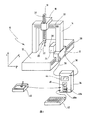
図1では、新たな装置の好ましい実施形態としての座標測定機について、参照番号10によりその全体を示している。座標測定機10は、ここでは構台設計で表されており、同じく例証として理解されるべきである。本発明は、特定の枠構造に制限されず、例えば水平方向アーム設計の座標測定機に使用してもよい。さらに、本発明の範囲において重要なことは、プローブヘッドと加工品との間の相対的な動きのみであるので、本発明は加工品が静止したプローブヘッドに対して移動する機械に使用してもよい。
In FIG. 1, a coordinate measuring machine as a preferred embodiment of a new apparatus is generally indicated by
座標測定機10は基部12を有し、その基部12上に、ドライブ15を併せ持つ構台14が配置されている。構台14は、ドライブ15により習慣的にy軸と呼ばれる軸方向に沿って移動することができる。
x方向に移動することができる担架16は、構台14の上部ブリッジ上に配置されている。担架16は、z方向に移動することができるラム18を有している。ラム18の下部自由端には、触針22を含むプローブヘッド20が設けられている。その自由端に、触針22は、加工品26上の表面点24に接触するために使用されるプローブボール23を有している(図2参照)。
The coordinate measuring
The
参照番号28、30、32は、座標測定機10の軸方向と平行に配置されている線状スケールを示す。これらは構台14、担架16およびラム18の運動位置を測定するために、例えば、適切なセンサー(図示せず)により読み出し可能なガラススケールである。これらの測定値を用いて、座標測定機10の測定容積内のプローブヘッド20の位置を定めることができる。接触された表面点24の空間座標は、プローブヘッドの位置から測定することができる。
参照番号34は、数値化・制御装置を示し、その装置34は、コード36、38を通じて座標測定機10のドライブとセンサに接続されている。この実施形態では、制御コンソール40とキーパッド42に数値化・制御装置34は、さらに接続されている。制御コンソール40は、座標測定機10の手動制御を可能にする。キーパッド42は、操作パラメータを入力し、測定プログラム等を選択することを可能にする。
ここでの制御装置34は、測定結果とパラメータ値などを出力することができるディスプレイ44を有している。制御装置34は、プロセッサー46と、ここでは簡略化された様式で2つのメモリ区域48a、48bで表されているメモリ48とをさらに有している。触針のヒステリシス効果は補正データ記録を用いて、表面点24に接触する際に最小限にすることができるが、それらの補正データ記録はメモリ区域48a、48bに保存される。好ましい実施形態では、補正データ記録は、触針22が移動することができる各軸方向について保存される。
The
図2は、非常に簡略化された表示ではあるが、座標測定機10のプローブヘッド20を詳細に示す。
触針22は、移動部50上に配置され、その移動部50は、2つの板ばね52、54を通じてプローブヘッド基部56に接続されている。板ばね52、54により、触針22を含む移動部50は、プローブヘッド基部56に対して移動することができる。2つの相互に反対の運動方向は、矢印58、60で示されている。
FIG. 2 shows the
The
当業者は、図2で表されるプローブヘッド20が、簡略化された表示により一軸方向58、60のみに触針22を移動させることができると分かるであろう。さらに、板ばね52、54が、当業者に周知のように、2つの他の軸方向での触針22の展開に対して与えられてもよい。
参照番号62は、アクチュエータを示し、そのアクチュエータ62により部分50は、プローブヘッド基部56に対して移動することができる。本実施形態では、アクチュエータ62は、2つの肢部64、66の間に配置されるプランジャーコイルである。一方の肢部64は、移動部50に接続されており、他方の肢部66は、プローブヘッド基部56に接続されている。アクチュエータ62は、別々に肢部64、66を押圧するか、または、それらの肢部を共に引くことができ、そのために触針22は部分50とともに空間方向58または、空間方向60に移動する。
Those skilled in the art will appreciate that the
参照番号68は、同じく2つの肢部64、66の間に配置されているセンサを示す。センサ68は、ここではスケール70で表されており、触針22の現在の変位X(参照番号22’により表される)を計測的に記録することを可能にする。センサ68は、プランジャーコイル、ホールセンサ、光学センサまたは別の適切な位置もしくは長さセンサであってもよい。
当業者は、プローブヘッド20が能動プローブヘッドであり、そのヘッド内の触針22がアクチュエータ62により移動し、画定された接触力を生成することができると分かるであろう。選択肢として、本発明はさらに、アクチュエータ62を有していない受動プローブヘッドに利用してもよい。
図3では、制御装置34のメモリ48内に保存される補正データ記録の全体が参照番号74により示されている。補正データ記録74は、ここではヒステリシス曲線の形で表されている。運動方向58、60での触針22の変位が、基底座標系の横座標76上で示されている。触針22が対応する変位の後に加工品26の表面点24上に加えるヒステリシス力が、縦座標78に示されている。表示される例示的な実施形態では、触針2の変位は、横座標76上ではmmで示されている。縦座標78上のヒステリシス力は、mNで示されている。
One skilled in the art will appreciate that the
In FIG. 3, the entire correction data record stored in the memory 48 of the
参照番号80、82、84、86、88は、補正データ記録74の様々な補正値を示す。表示される補正値は、図5を用いて以下で説明するように、補正データ記録74の標本点として計測されている。さらに、表示される補正値は(ここでは明確には言及されていない他の補正値とともに)制御装置34のメモリ48内に保存されている。保存された補正値の間にある補正値は、制御装置34による補間を通じて有利に定められる。
図3の補正データ記録74はx方向(負および正)での触針22の変位を例示している。類似の補正データ記録もまた他の2つの軸方向y、zについて、制御装置34のメモリ48内に保存されていることが理解されるであろう。
触針22が加工品26上の表面点24に接触する接触力は、補正データ記録74により以下の通りに補正される。座標測定機10の最初の設定の後、または任意の新規設定の後は、触針がヒステリシスのない状態であると仮定される。触針22が、初めて座標原点90に対応するその静止位置から、0.5mm(またはそれ以上)移動するまで補正は初期には行われない。触針22が正のx方向に1mmだけ移動すると仮定する。上記の変位に対して、補正データ記録74から、約3mNのヒステリシス力を読み出すことができる。触針22が正のx方向に1mmを超えて移動するまで、または、触針22が負のx方向に0.2mmだけ移動するまで(参照番号92)、すべての後続の接触力はこの補正値(参照番号82)で補正される。前者の場合、補正値は、曲線74上で補正値84の方向に「移動する」。後者の場合、触針が曲線74上で点92に達するまで、補正値82は保たれる。
The
The contact force with which the
この代わりとして、触針22が負のx方向に移動するが、曲線74上の点92にまだ達しなかったとき、補正値(すなわち、ここでは3mNのヒステリシス力)がすでに削減されていてもよい。例えば、先に選択された補正値82の百分率での縮小が、触針22が負のx方向に移動した程度に応じて実行されてもよい。
補正データ記録74の曲線形状から分かるように、最大の補正は、ここでは約4.5mN(補正値84)である。たとえ触針22が2.5mm以上移動するとしても、より強い接触力の補正は、ここでは起こらない。
Alternatively, when the
As can be seen from the curve shape of the
図3の曲線形状からさらに分かるように、ゼロの接触力補正(補正なし、またはゼロに等しいヒステリシス力)に対応する補正値88は、横座標76上の補正値80の少し前にある。上記の曲線形状は、接触力の補正が削減されるか、または初期に取り消されて、対照的に後まで始まらないことを保証するので有利である。これは、続いて測定誤差を生成することがありえる、あまりにも強力な補正を回避することになる。
As can be further seen from the curve shape of FIG. 3, the
図4は、簡略化されたフローチャートを用いて新たな方法の好ましい例示的な実施形態を示す。工程96にしたがって、ユーザーにより望まれる接触力DFは、最初にパラメータ値として読み取られる。ユーザーは、キーパッド42によりコントローラ34に所望の接触力DFを入力することができる。
測定値実行の開始においては、工程98にしたがって、ヒステリシス力HF(Xmax)をメモリ48から読み出す。言い換えると、適切な補正値が、先に検出された触針22の変位に応じて補正データ記録74から取り出される。座標測定機10を設定した後に、補正値HF=0が最初に利用される。
FIG. 4 illustrates a preferred exemplary embodiment of the new method using a simplified flowchart. According to step 96, the contact force DF desired by the user is first read as a parameter value. The user can input a desired contact force DF to the
At the start of measurement value execution, the hysteresis force HF (Xmax) is read from the memory 48 in accordance with
その後、工程100にしたがって、所望の接触力が、所望の接触力DFと補正データ記録74からのヒステリシス力HFとの間の差として計算される。言い換えると、所望の接触力は、ヒステリシス効果によって存在するヒステリシス力により削減される。プローブヘッドが受動プローブヘッドである場合、工程102にしたがって、触針22の設定点の変位は、所望の接触力に応じて測定される。能動プローブヘッドの場合、アクチュエータ62は、デフォルト値として所望の接触力で駆動される。
Thereafter, according to
工程104にしたがって、表面点24が所望の接触力で走査され、実際の接触力は、既存のヒステリシス力による所望の接触力DFに対応している。
工程106にしたがって、触針22の変位Xが測定される。変位Xは、表面点24のX空間座標を測定するために、ならびに、接触力の本発明による補正のために必要である。
工程108にしたがって、能動プローブヘッドの場合、アクチュエータ62により生成される接触力が、さらに測定される。プランジャーコイルがアクチュエータとして使用される場合、例えばプランジャーコイルを流れる電流が測定されてもよい。
According to step 104, the
According to step 106, the displacement X of the
According to step 108, in the case of an active probe head, the contact force generated by the
工程110にしたがって、実際の接触力が、計測的に記録されたアクチュエータ力とヒステリシス力HFとの合計として定められる。工程100での除算とステップ110での和算が、ここでは図3の表示にしたがって選択される適切な符号で実行されると理解するべきである。
工程112にしたがって、実際の接触力が、ディスプレイ44上に表示されてもよい。工程114にしたがって、触針22の変形が、実際の接触力を用いてさらに測定される。その後、工程116にしたがって、走査された表面点24の空間座標が測定され、触針22の変形は、好ましくは、実際の接触力に基づいて考慮されている。見出される空間座標は、ディスプレイ44に出力されてもよい。
According to step 110, the actual contact force is determined as the sum of the metered actuator force and hysteresis force HF. It should be understood that the division at
According to step 112, the actual contact force may be displayed on the
工程118にしたがって、表面点24に接触する際の触針22の変位が、同じ空間方向での最新の最大変位Xmaxよりも大きいかどうかについての第1の判定が行われる。該当しない場合、ループ120にしたがって、利用された最後の補正値が接触力のために保たれる。そうでない場合、工程122にしたがって、最新の変位Xが、新たな最大値Xmaxとして取り入れられ、工程98にしたがって、新たな相応して適合する補正値が、座標データ記録74から選択される。その後、ループ124にしたがって、次の測定プロセスが、新たな補正値を使用することにより実行される。
According to step 118, the displacement of the
図5は、例示的な実施形態を説明するための簡略化されたフローチャートを示し、そのフローチャートを用いて図3の補正データ記録74を記録することができる。
工程126にしたがって、触針22は、最初にヒステリシスがないと仮定される開始状態に設定される。その後、工程128にしたがって、力センサ(図示せず)上の表面点に接触する。力センサは、較正部品の働きをする。工程130にしたがって、力センサを用いて第1の接触力TF1が測定される。接触力TF1を参照値としてヒステリシスのない(少なくとも、そのように仮定される)変位のために利用する。
FIG. 5 shows a simplified flowchart for illustrating an exemplary embodiment, which can be used to record the
According to step 126, the
工程132にしたがって、触針はその後、一空間方向に値xだけ移動する。その後、力センサ上の同じ表面点に、再び接触し(工程134)、工程136にしたがって、接触力TF2(x)が測定される。通常、接触力TF1とTF2(x)は、触針22のヒステリシス作用のために互いに異なる。
工程138にしたがって、接触力の間の差TF2(x)−TF1はヒステリシス力HF(x)として、すなわち補正データ記録74の補正値として保存される(工程140)。その後、ループ142にしたがって、補正データ記録74の次の補正値が測定される。
According to step 132, the stylus is then moved by a value x in one spatial direction. Thereafter, the same surface point on the force sensor is contacted again (step 134), and the contact force TF2 (x) is measured according to
According to step 138, the difference TF2 (x) -TF1 between the contact forces is stored as hysteresis force HF (x), ie as a correction value in correction data record 74 (step 140). Thereafter, the next correction value of the
好ましくは、補正データ記録74は補正値80〜88とともに較正プロセスで記録され、同一の補正データ記録74がすべての後続の接触操作に利用されるように、座標測定機10のメモリ48に永久に保存される。
Preferably, the
Claims (12)
プローブヘッド基部(56)と、前記プローブヘッド基部(56)に対して画定された静止位置を有し、かつ移動可能である触針(22)とを有するプローブヘッド(20)を供給する工程と、
前記触針(22)が画定された接触力で前記表面点(24)に触れるまで、前記プローブヘッド(22)を前記加工品(26)に対して移動させる工程と
を含み、
前記静止位置に対する前記触針(22)のヒステリシス作用を表す補正データ記録(48;74)が準備されて、前記接触力が前記補正データ記録(48;74)を用いて測定されることを特徴とする方法。 A method for contacting a surface point (24) on a workpiece (26) and measuring a spatial coordinate of said surface point, comprising:
Providing a probe head (20) having a probe head base (56) and a stylus (22) having a stationary position defined relative to said probe head base (56) and movable; ,
Moving the probe head (22) relative to the workpiece (26) until the stylus (22) touches the surface point (24) with a defined contact force;
A correction data record (48; 74) representing the hysteresis effect of the stylus (22) with respect to the rest position is prepared, and the contact force is measured using the correction data record (48; 74). And how to.
プローブヘッド基部(56)と、前記プローブヘッド基部(56)に対して画定された静止位置を有し、かつ移動可能である触針(22)とを有しているプローブヘッド(20)と、
前記表面点(24)を前記触針(22)と前記画定された接触力で接触させるために、前記加工品(26)に対して前記プローブヘッド(20)を移動させるための少なくとも1つのドライブ(15)と
を含み、
前記静止位置に対する前記触針(22)のヒステリシス作用を表す補正データ記録(74)が提供されるメモリ(48)と、前記補正データ記録(74)を用いて前記接触力を定めるように設計されている計算ユニット(46)とで特徴付けられる装置。 A device for contacting a surface point (24) on a workpiece (26), in particular for measuring the spatial coordinates of said surface point,
A probe head (20) having a probe head base (56) and a stylus (22) having a stationary position defined relative to said probe head base (56) and movable;
At least one drive for moving the probe head (20) relative to the workpiece (26) to bring the surface point (24) into contact with the stylus (22) with the defined contact force. (15) and
Designed to determine the contact force using a memory (48) provided with a correction data record (74) representing the hysteresis effect of the stylus (22) relative to the rest position and the correction data record (74). Characterized by a computing unit (46).
Applications Claiming Priority (3)
| Application Number | Priority Date | Filing Date | Title |
|---|---|---|---|
| DE102006023031.0 | 2006-05-10 | ||
| DE102006023031A DE102006023031A1 (en) | 2006-05-10 | 2006-05-10 | Method and device for probing a surface point on a workpiece |
| PCT/EP2007/003788 WO2007128444A1 (en) | 2006-05-10 | 2007-04-28 | Method and apparatus for scanning a surface point on a workpiece |
Publications (2)
| Publication Number | Publication Date |
|---|---|
| JP2009536325A JP2009536325A (en) | 2009-10-08 |
| JP5253382B2 true JP5253382B2 (en) | 2013-07-31 |
Family
ID=38176883
Family Applications (1)
| Application Number | Title | Priority Date | Filing Date |
|---|---|---|---|
| JP2009508187A Expired - Fee Related JP5253382B2 (en) | 2006-05-10 | 2007-04-28 | Method and apparatus for contacting a surface point of a workpiece |
Country Status (5)
| Country | Link |
|---|---|
| US (1) | US7788820B2 (en) |
| EP (1) | EP2016368B1 (en) |
| JP (1) | JP5253382B2 (en) |
| DE (2) | DE102006023031A1 (en) |
| WO (1) | WO2007128444A1 (en) |
Families Citing this family (15)
| Publication number | Priority date | Publication date | Assignee | Title |
|---|---|---|---|---|
| US7249421B2 (en) | 2005-12-22 | 2007-07-31 | Hexagon Metrology Ab | Hysteresis compensation in a coordinate measurement machine |
| DE102006023031A1 (en) * | 2006-05-10 | 2007-11-15 | Carl Zeiss Industrielle Messtechnik Gmbh | Method and device for probing a surface point on a workpiece |
| US8858853B2 (en) * | 2008-04-04 | 2014-10-14 | The Boeing Company | Formed sheet metal composite tooling |
| US7752003B2 (en) | 2008-06-27 | 2010-07-06 | Hexagon Metrology, Inc. | Hysteresis compensation in a coordinate measurement machine |
| WO2010030117A2 (en) * | 2008-09-09 | 2010-03-18 | Kim Ju Tae | Floor construction apparatus |
| DE102008063236B4 (en) | 2008-12-15 | 2019-07-11 | Carl Zeiss Industrielle Messtechnik Gmbh | Method for calibrating a measuring force on a coordinate measuring machine |
| JP5371532B2 (en) * | 2009-04-23 | 2013-12-18 | 株式会社ミツトヨ | CMM |
| DE102009020294A1 (en) * | 2009-05-07 | 2010-11-18 | Mahr Gmbh | Method and device for measuring a surface profile |
| DE102010026892A1 (en) * | 2010-04-09 | 2011-10-13 | Stotz Feinmesstechnik Gmbh | Device for measuring objects |
| US9671257B2 (en) * | 2011-07-08 | 2017-06-06 | Carl Zeiss Industrielle Messtechnik Gmbh | Correcting and/or preventing errors during the measurement of coordinates of a workpiece |
| EP2984442B1 (en) | 2013-04-02 | 2017-03-08 | Carl Zeiss Industrielle Messtechnik GmbH | Method for determining a shape contour on an object to be measured |
| WO2015093244A1 (en) * | 2013-12-18 | 2015-06-25 | コニカミノルタ株式会社 | Measurement probe and shape measurement device |
| DE102014220313A1 (en) * | 2014-10-07 | 2016-04-07 | Carl Zeiss Industrielle Messtechnik Gmbh | Detecting geometric deviations of a motion control in a coordinate measuring machine or a machine tool |
| TWI786221B (en) * | 2017-12-22 | 2022-12-11 | 瑞士商謹觀股份公司 | Machine-tool with an optical measuring device for the three-dimensional registration between the tool-holder and the workpiece holder |
| CN116625242B (en) * | 2023-07-26 | 2023-10-03 | 青岛科技大学 | Path planning method and system for optical three-coordinate measuring machine, electronic equipment and medium |
Family Cites Families (25)
| Publication number | Priority date | Publication date | Assignee | Title |
|---|---|---|---|---|
| JPS6150007A (en) | 1984-08-18 | 1986-03-12 | Mitsutoyo Mfg Co Ltd | Tracer for measuring surface shape |
| US5339535A (en) * | 1990-02-23 | 1994-08-23 | Renishaw Metrology Limited | Touch probe |
| US5491904A (en) * | 1990-02-23 | 1996-02-20 | Mcmurtry; David R. | Touch probe |
| US5253428A (en) | 1990-02-23 | 1993-10-19 | Renishaw Plc | Touch probe |
| GB9004117D0 (en) * | 1990-02-23 | 1990-04-18 | Renishaw Plc | Touch probe |
| DE4027136A1 (en) | 1990-08-28 | 1992-03-05 | Leitz Messtechnik | CENTERING DEVICE FOR MECHANICAL PROBE |
| DE4204632A1 (en) | 1990-08-28 | 1993-08-19 | Leitz Messtechnik | Centring unit for mechanical scanning head with follower and scanner - has two resetting elements reacting to follower in contrasting manner and one only multipart stop is provided for one reset element. |
| JPH05506103A (en) * | 1991-02-25 | 1993-09-02 | レニショウ メタロジィ リミテッド | contact probe |
| EP0501710B1 (en) * | 1991-02-25 | 1995-04-12 | Renishaw Metrology Limited | Touch probe |
| AU3794893A (en) * | 1992-03-13 | 1993-10-05 | Park Scientific Instruments Corp. | Scanning probe microscope |
| JPH0783650A (en) * | 1993-09-10 | 1995-03-28 | Hitachi Constr Mach Co Ltd | Measured data correction and measured angle error detection in scanning probe microscope |
| JPH07134133A (en) * | 1993-11-12 | 1995-05-23 | Hitachi Ltd | Scanning type probe microscope |
| JPH08304059A (en) * | 1995-05-10 | 1996-11-22 | Mitsutoyo Corp | Stylus support device |
| JP3153111B2 (en) * | 1995-09-18 | 2001-04-03 | 株式会社ミツトヨ | Manually operated CMM |
| JP3502709B2 (en) * | 1995-11-20 | 2004-03-02 | 大日本スクリーン製造株式会社 | Stylus displacement control device and gravure engraving machine using the same |
| US6058618A (en) * | 1997-09-09 | 2000-05-09 | Giddings & Lewis, Inc. | Coordinate measuring machine |
| JPH11264833A (en) * | 1998-03-18 | 1999-09-28 | Nikon Corp | Scanning type probe microscope and method for driving the probe |
| JP2002350318A (en) * | 2001-05-25 | 2002-12-04 | Olympus Optical Co Ltd | Scanner device |
| JP3820357B2 (en) * | 2001-08-07 | 2006-09-13 | 株式会社ミツトヨ | Measuring method and measuring apparatus |
| JP2003241838A (en) * | 2002-02-20 | 2003-08-29 | Japan Science & Technology Corp | Positioning apparatus |
| DE10229824A1 (en) | 2002-06-28 | 2004-01-15 | Carl Zeiss | Method for operating a coordinate measuring machine that can be operated in at least two operating modes |
| JP2005055345A (en) * | 2003-08-06 | 2005-03-03 | Mitsutoyo Corp | Displacement measuring device, surface profile measuring device |
| DE102004007968B4 (en) * | 2004-02-18 | 2006-02-09 | Carl Zeiss Industrielle Messtechnik Gmbh | Method for probing a workpiece with a coordinate measuring machine |
| JP4652011B2 (en) * | 2004-10-13 | 2011-03-16 | 株式会社ミツトヨ | Three-dimensional coordinate measurement system and part program used therefor |
| DE102006023031A1 (en) * | 2006-05-10 | 2007-11-15 | Carl Zeiss Industrielle Messtechnik Gmbh | Method and device for probing a surface point on a workpiece |
-
2006
- 2006-05-10 DE DE102006023031A patent/DE102006023031A1/en not_active Withdrawn
-
2007
- 2007-04-28 EP EP07724715A patent/EP2016368B1/en not_active Not-in-force
- 2007-04-28 JP JP2009508187A patent/JP5253382B2/en not_active Expired - Fee Related
- 2007-04-28 DE DE502007003310T patent/DE502007003310D1/en active Active
- 2007-04-28 WO PCT/EP2007/003788 patent/WO2007128444A1/en active Application Filing
-
2008
- 2008-11-07 US US12/267,123 patent/US7788820B2/en not_active Expired - Fee Related
Also Published As
| Publication number | Publication date |
|---|---|
| US7788820B2 (en) | 2010-09-07 |
| US20090172962A1 (en) | 2009-07-09 |
| DE502007003310D1 (en) | 2010-05-12 |
| WO2007128444A1 (en) | 2007-11-15 |
| JP2009536325A (en) | 2009-10-08 |
| EP2016368B1 (en) | 2010-03-31 |
| EP2016368A1 (en) | 2009-01-21 |
| DE102006023031A1 (en) | 2007-11-15 |
Similar Documents
| Publication | Publication Date | Title |
|---|---|---|
| JP5253382B2 (en) | Method and apparatus for contacting a surface point of a workpiece | |
| JP5400056B2 (en) | Method for calibrating a coordinate measuring machine | |
| JP5221004B2 (en) | Measuring device, surface texture measuring method, and surface texture measuring program | |
| JP5449174B2 (en) | Method for correcting the measurement value of a coordinate measuring machine and coordinate measuring machine | |
| JP6254456B2 (en) | CMM and correction matrix calculation method using CMM | |
| US8074497B2 (en) | Indentation testing instrument and indentation testing method | |
| CN105277148B (en) | The bearing calibration of the evaluated error of shape measuring apparatus and shape measuring apparatus | |
| CN105588533B (en) | Shape measuring apparatus and process for measuring shape | |
| JP5816475B2 (en) | Industrial machinery | |
| US11221201B2 (en) | Profile measuring machine and profile measuring method | |
| JP2004045088A (en) | Device and method for measuring surface profile | |
| CN104034618A (en) | Hardness tester | |
| CN107782223A (en) | Coordinate measuring apparatus and method for correcting coordinate | |
| JP2017537322A (en) | Method for determining the measurement conditions of a roughness sensor, method for measuring the roughness of a workpiece surface, computer program product and measuring device designed to carry out the method | |
| JP2005055282A (en) | Measuring method and measuring device | |
| JP2007142093A (en) | Stage device, electron beam irradiation device and exposure device | |
| JP5371532B2 (en) | CMM | |
| JP6474587B2 (en) | Measurement value correction method, measurement value correction program, and measurement apparatus | |
| JP3820357B2 (en) | Measuring method and measuring apparatus | |
| EP2636992B1 (en) | Controller for surface texture measurement device and method for controlling the same | |
| JP4652011B2 (en) | Three-dimensional coordinate measurement system and part program used therefor | |
| JP5064725B2 (en) | Shape measurement method | |
| JP2017198532A (en) | Shape measurement method of shape measurement device and shape measurement device | |
| EP2405234B1 (en) | Form measuring instrument | |
| JP2009534764A (en) | Method and apparatus for triggering the position of a machine part |
Legal Events
| Date | Code | Title | Description |
|---|---|---|---|
| A131 | Notification of reasons for refusal |
Free format text: JAPANESE INTERMEDIATE CODE: A131 Effective date: 20120412 |
|
| TRDD | Decision of grant or rejection written | ||
| A01 | Written decision to grant a patent or to grant a registration (utility model) |
Free format text: JAPANESE INTERMEDIATE CODE: A01 Effective date: 20130321 |
|
| A61 | First payment of annual fees (during grant procedure) |
Free format text: JAPANESE INTERMEDIATE CODE: A61 Effective date: 20130416 |
|
| R150 | Certificate of patent or registration of utility model |
Free format text: JAPANESE INTERMEDIATE CODE: R150 |
|
| FPAY | Renewal fee payment (event date is renewal date of database) |
Free format text: PAYMENT UNTIL: 20160426 Year of fee payment: 3 |
|
| R250 | Receipt of annual fees |
Free format text: JAPANESE INTERMEDIATE CODE: R250 |
|
| R250 | Receipt of annual fees |
Free format text: JAPANESE INTERMEDIATE CODE: R250 |
|
| LAPS | Cancellation because of no payment of annual fees |