JP5201045B2 - 2-stage compression rotary compressor - Google Patents
2-stage compression rotary compressor Download PDFInfo
- Publication number
- JP5201045B2 JP5201045B2 JP2009072896A JP2009072896A JP5201045B2 JP 5201045 B2 JP5201045 B2 JP 5201045B2 JP 2009072896 A JP2009072896 A JP 2009072896A JP 2009072896 A JP2009072896 A JP 2009072896A JP 5201045 B2 JP5201045 B2 JP 5201045B2
- Authority
- JP
- Japan
- Prior art keywords
- stage
- low
- compression
- chamber
- cylinder
- Prior art date
- Legal status (The legal status is an assumption and is not a legal conclusion. Google has not performed a legal analysis and makes no representation as to the accuracy of the status listed.)
- Active
Links
Images


Landscapes
- Applications Or Details Of Rotary Compressors (AREA)
Description
本発明は、空気調和機の冷凍サイクルに使用される2段圧縮ロータリ圧縮機(以下、単に「ロータリ圧縮機」ともいう。)に関する。 The present invention relates to a two-stage compression rotary compressor (hereinafter also simply referred to as “rotary compressor”) used in a refrigeration cycle of an air conditioner.
一般に、2段圧縮ロータリ圧縮機は、密閉された円筒状の圧縮機筐体内部に、低段側圧縮部及び高段側圧縮部と、低段側圧縮部及び高段側圧縮部を駆動するモータと、を備え、圧縮機本体筐体の側方にアキュムレータを備えている。 Generally, a two-stage compression rotary compressor drives a low-stage compression section and a high-stage compression section, and a low-stage compression section and a high-stage compression section inside a sealed cylindrical compressor casing. And an accumulator on the side of the compressor body housing.
従来、密閉容器内にモータと、該モータにて駆動される低段側圧縮部及び高段側圧縮部を備え、前記低段側圧縮部で圧縮され、吐出された冷媒ガスを前記高段側圧縮部に吸引し、圧縮して吐出する2段圧縮ロータリ圧縮機において、前記高段側圧縮部の吐出孔を前記低段側吐出孔よりも小さくした2段圧縮ロータリ圧縮機が開示されている(例えば、特許文献1参照)。 Conventionally, a sealed container is provided with a motor, a low-stage compression section and a high-stage compression section driven by the motor, and the refrigerant gas compressed and discharged by the low-stage compression section is discharged to the high-stage side. In a two-stage compression rotary compressor that sucks into a compression section and compresses and discharges the two-stage compression rotary compressor, the discharge hole of the high-stage compression section is smaller than the low-stage discharge hole. (For example, refer to Patent Document 1).
しかしながら、上記従来の技術によれば、低段側圧縮部及び高段側圧縮部の吐出弁の厚さを同一とし、低段側吐出孔を高段側吐出孔より大きくすると、吐出孔が大きくなった分、低段側吐出弁の差圧受圧面積が大きくなる。そのため、低段側吐出弁の凹み変形量が大きくなり、低段側吐出弁が吐出孔のエッジ部と高面圧で当接し、低段側吐出弁及びエッジ部の磨耗が早まって耐久性が低下する、という問題があった。 However, according to the above conventional technique, when the thickness of the discharge valve of the low-stage compression section and the high-stage compression section is the same, and the low-stage discharge hole is larger than the high-stage discharge hole, the discharge hole becomes large. Therefore, the differential pressure receiving area of the low stage side discharge valve is increased. Therefore, the amount of dent deformation on the low-stage discharge valve increases, the low-stage discharge valve abuts against the edge of the discharge hole with high surface pressure, and wear of the low-stage discharge valve and edge is accelerated and durability is increased. There was a problem of lowering.
また、低段側圧縮部及び高段側圧縮部の吐出弁厚さが同一で、高段側圧縮部よりも低段側圧縮部の方が吐出孔径が大きいため、高段側吐出弁に対して低段側吐出弁の閉じ遅れが発生し、吐出された冷媒がマフラー室から圧縮室へ逆流しやすくなり、圧縮効率が低下する、という問題があった。 Also, the discharge valve thickness of the low-stage compression section and the high-stage compression section is the same, and the discharge hole diameter of the low-stage compression section is larger than that of the high-stage compression section. As a result, there is a problem in that the closing delay of the low-stage discharge valve occurs, the discharged refrigerant easily flows back from the muffler chamber to the compression chamber, and the compression efficiency decreases.
本発明は、上記に鑑みてなされたものであって、低段側圧縮部の低段側吐出弁の変形を抑えて低段側吐出弁の耐久性を向上させるとともに、低段側吐出弁の閉じ遅れを防止して圧縮効率を向上することができる2段圧縮ロータリ圧縮機を得ることを目的とする。 The present invention has been made in view of the above, and while suppressing the deformation of the low-stage discharge valve of the low-stage compression section, the durability of the low-stage discharge valve is improved, and the low-stage discharge valve It is an object of the present invention to obtain a two-stage compression rotary compressor that can prevent the closing delay and improve the compression efficiency.
上述した課題を解決し、目的を達成するために、本発明は、低段側圧縮部、高段側圧縮部及び該低段側、高段側圧縮部を駆動するモータを圧縮機筺体内に収容し、前記低段側圧縮部で圧縮され吐出された冷媒を前記高段側圧縮部に吸入し、さらに圧縮して吐出する2段圧縮ロータリ圧縮機において、前記高段側圧縮部の高段側吐出孔を前記低段側圧縮部の低段側吐出孔よりも小さくし、前記低段側吐出孔の出口側に設置されたリード弁型の低段側吐出弁の厚さを、前記高段側吐出孔の出口側に設置されたリード弁型の高段側吐出弁の厚さより厚くしたことを特徴とする。
In order to solve the above-described problems and achieve the object, the present invention includes a low-stage compression section, a high-stage compression section, and a motor for driving the low-stage compression section and the high-stage compression section in the compressor housing. In the two-stage compression rotary compressor that stores, sucks the refrigerant compressed and discharged by the low-stage compression section into the high-stage compression section, and further compresses and discharges the refrigerant, the high-stage of the high-stage compression section The side discharge hole is made smaller than the low stage side discharge hole of the low stage side compression portion, and the thickness of the reed valve type low stage side discharge valve installed on the outlet side of the low stage side discharge hole is set to the high level. It is characterized by being thicker than the thickness of the reed valve type high- stage discharge valve installed on the outlet side of the stage-side discharge hole .
本発明にかかる2段圧縮ロータリ圧縮機は、低段側吐出弁の厚さを、高段側吐出弁の厚さより厚くしたことにより、低段側吐出弁の変形量を抑えて吐出弁の耐久性を向上することができる、という効果を奏する。また、低段側吐出弁の閉じ遅れを防止して圧縮効率を向上することができる。 In the two-stage compression rotary compressor according to the present invention, the thickness of the low-stage side discharge valve is made larger than the thickness of the high-stage side discharge valve, so that the deformation amount of the low-stage side discharge valve is suppressed and the durability of the discharge valve is improved. The effect that it can improve property is produced. Further, it is possible to improve the compression efficiency by preventing the closing delay of the low-stage discharge valve.
以下に、本発明にかかる2段圧縮ロータリ圧縮機の実施例を図面に基づいて詳細に説明する。なお、この実施例によりこの発明が限定されるものではない。 Embodiments of a two-stage compression rotary compressor according to the present invention will be described below in detail with reference to the drawings. Note that the present invention is not limited to the embodiments.
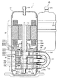
図1は、本発明にかかる2段圧縮ロータリ圧縮機の実施例を示す縦断面図であり、図2は、実施例の2段圧縮ロータリ圧縮機の低段側圧縮部及び高段側圧縮部の横断面図であり、図3は、図1のA−A線に沿う横断面図であり、図4は、実施例の2段圧縮ロータリ圧縮機の低段側端板の横断面図であり、図5は、図4のC−C線に沿う断面図であり、図6は、図1のB−B線に沿う横断面図であり、図7は、実施例の2段圧縮ロータリ圧縮機の高段側端板の横断面図であり、図8は、図7のD−D線に沿う断面図であり、図9は、実施例の2段圧縮ロータリ圧縮機の側面図である。 FIG. 1 is a longitudinal sectional view showing an embodiment of a two-stage compression rotary compressor according to the present invention. FIG. 2 shows a low-stage compression section and a high-stage compression section of the two-stage compression rotary compressor of the embodiment. 3 is a cross-sectional view taken along line AA in FIG. 1, and FIG. 4 is a cross-sectional view of the low-stage side end plate of the two-stage compression rotary compressor of the embodiment. 5 is a cross-sectional view taken along line CC in FIG. 4, FIG. 6 is a cross-sectional view taken along line BB in FIG. 1, and FIG. 7 is a two-stage compression rotary according to the embodiment. FIG. 8 is a cross-sectional view of the high-stage end plate of the compressor, FIG. 8 is a cross-sectional view taken along the line DD in FIG. 7, and FIG. 9 is a side view of the two-stage compression rotary compressor of the embodiment. is there.
図1に示すように、実施例の2段圧縮ロータリ圧縮機1は、密閉された円筒状の圧縮機筐体10の内部に、圧縮部12と、圧縮部12を駆動するモータ11と、を備えている。
As shown in FIG. 1, the two-stage compression rotary compressor 1 of the embodiment includes a
モータ11のステータ111は、圧縮機筐体10の内周面に焼きばめされて固定されている。モータ11のロータ112は、ステータ111の中央部に配置され、モータ11と圧縮部12とを機械的に接続する回転軸15に焼きばめされて固定されている。
The stator 111 of the
圧縮部12は、低段側圧縮部12Lと、低段側圧縮部12Lに直列に接続され低段側圧縮部12Lの上側に積層されて設置された高段側圧縮部12Hと、を備えて成る。図2に示すように、低段側圧縮部12Lは、短い円筒状の低段側シリンダ121Lを備え、高段側圧縮部12Hは、短い円筒状の高段側シリンダ121Hを備えている。
The
低段側シリンダ121L及び高段側シリンダ121Hには、夫々モータ11と同芯に、低段側、高段側シリンダ内壁123L、123Hが形成されている。夫々のシリンダ内壁123L、123H内には、低段、高段シリンダ内径よりも小さい外径の円筒状の低段側、高段側ピストン125L,125Hが夫々配置され、夫々のシリンダ内壁123L、123Hと、低段側、高段側ピストン125L、125Hの間に、冷媒を吸入し圧縮して吐出する低段側、高段側作動室130L、130H(圧縮空間)が形成される。
The low-
低段、高段シリンダ121L、121Hには、低段、高段シリンダ内壁123L、123Hから径方向に、シリンダ高さ全域に亘る低段側、高段側ベーン溝が形成され、この溝内に、板状の低段側、高段側ベーン127L、127Hが嵌合されている。低段側、高段側ベーン127L、127Hの圧縮機筐体10側には、低段側、高段側スプリング129L、129Hが装着されている。
The low-stage and high-
この低段側、高段側スプリング129L、129Hの反撥力により、低段側、高段側ベーン127L、127Hの先端が、低段側、高段側ピストン125L、125Hの外周面に押し付けられ、低段側、高段側ベーン127L、127Hにより、低段側、高段側作動室130L、130Hが、低段側、高段側吸入室131L、131Hと、低段側、高段側圧縮室133L、133Hとに区画される。
Due to the repulsive force of the low-stage and high-
低段側、高段側シリンダ121L、121Hには、低段側、高段側吸入室131L、131Hに冷媒を吸入するために、低段側、高段側吸入室131L、131Hに連通する低段側、高段側吸入孔135L、135Hが設けられ、低段側シリンダ121Lの低段側吸入孔135L、高段側シリンダ121Hの高段側吸入孔135H及び後述する低段側マフラー吐出孔210Lは同一周方向に向けて設けられている。
The low-stage and high-
また、低段側シリンダ121Lと高段側シリンダ121Hとの間には、中間仕切板140が設置され、低段側シリンダ121Lの低段作動室130Lと高段側シリンダ121Hの高段作動室130Hとを区画している。低段側シリンダ121Lの下側には、低段側端板160Lが設置され、低段側シリンダ121Lの低段作動室130Lの下部を閉塞している。また、高段側シリンダ121Hの上側には、高段側端板160Hが設置され、高段側シリンダ121Hの高段作動室130Hの上部を閉塞している。
Further, an
低段側端板160Lには、下軸受け部161Lが形成され、下軸受け部161Lに、回転軸15の下部151が回転自在に支持されている。また、高段側端板160Hには、上軸受け部161Hが形成され、上軸受け部161Hに、回転軸15の中間部153が回転自在に支持されている。
A
回転軸15は、互いに180°位相をずらして偏芯させた低段側偏芯部152Lと高段側偏芯部152Hとを備え、低段側偏芯部152Lは、低段側圧縮部12Lの低段側ピストン125Lを回転自在に保持し、高段側偏芯部152Hは、高段側圧縮部12Hの高段側ピストン125Hを回転自在に保持している。
The rotating
回転軸15が回転すると、低段側、高段側ピストン125L、125Hが、低段側、高段側シリンダ内壁123L、123Hに沿って低段側、高段側シリンダ121L、121H内を公転し、これに追随して低段側、高段側ベーン127L、127Hが往復運動する。この低段側、高段側ピストン125L、125H及び低段側、高段側ベーン127L、127Hの運動により、低段側、高段側吸入室131L、131H及び低段側、高段側圧縮室133L、133Hの容積が連続的に変化し、圧縮部12は、連続的に冷媒を吸入し、圧縮して吐出する。
When the
低段側端板160Lの下側には、低段側マフラーカバー170Lが設置され、低段側端板160Lとの間に低段側マフラー室180Lを形成している。そして、低段側圧縮部12Lの吐出部は、低段側マフラー室180Lに開口している。すなわち、低段側端板160Lには、低段側シリンダ121Lの低段側圧縮室133Lと低段側マフラー室180Lとを連通する低段側吐出孔190Lが設けられ、低段側吐出孔190Lの出口側には、圧縮された冷媒の逆流を防止する低段側吐出弁200Lが設置されている。
Below the low stage
実施例では、低段側吐出孔190Lの孔径を、後述の高段側吐出孔190Hの孔径よりも大きくしている。低段側吐出孔190Lの孔径を大きくすることにより、高段側圧縮部12Hよりも冷媒の体積流量が大きい低段側圧縮部12Lの流量抵抗を小さくすることができる。
In the embodiment, the hole diameter of the low-
図3及び図4に示すように、低段側マフラー室180Lは、環状に連通された1つの室であり、低段側圧縮部12Lの吐出側と高段側圧縮部12Hの吸入側とを連通する中間連通路の一部である。低段側マフラー室180Lは、吐出冷媒の圧力脈動を低減させる。
As shown in FIGS. 3 and 4, the low-
また、図4及び図5に示すように、低段側吐出弁200Lの上には、低段側吐出弁200Lの撓み開弁量を制限するための低段側吐出弁押さえ201Lが、低段側吐出弁200Lとともにリベット203により固定されている。また、低段側端板160Lの外周壁部には、低段側マフラー室180L内の冷媒を吐出する低段側マフラー吐出孔210Lが設けられている。低段側マフラー吐出孔210Lは、圧縮部12の低段側吸入孔135L、高段側吸入孔135Hと圧縮機筐体10の周方向の同一位相位置に、径方向に設けられている。
Further, as shown in FIGS. 4 and 5, a low-stage
高段側端板160Hの上側には、高段側マフラーカバー170Hが設置され、高段側端板160Hとの間に高段側マフラー室180Hを形成している。図6、図7及び図8に示すように、高段側端板160Hには、高段側シリンダ121Hの高段側圧縮室133Hと高段側マフラー室180Hとを連通する高段側吐出孔190Hが設けられ、高段側吐出孔190Hの出口側には、圧縮された冷媒の逆流を防止する高段側吐出弁200Hが設置されている。また、高段側吐出弁200Hの上には、高段側吐出弁200Hの撓み開弁量を制限するために、高段側吐出弁押さえ201Hが、高段側吐出弁200Hとともにリベット203により固定されている。高段側マフラー室180Hは、吐出冷媒の圧力脈動を低減させる。
A high stage
高段側マフラー室180Hの吐出部は、圧縮機筐体10内に連通している。圧縮機筐体10の天部には、冷凍サイクルの高圧側と接続し、高圧冷媒を冷凍サイクル側に吐出する吐出管107が接続されている。
The discharge part of the high-
低段側シリンダ121L、低段側端板160L、低段側マフラーカバー170L、高段側シリンダ121H、高段側端板160H、高段側マフラーカバー170H及び中間仕切板140は、図示しないボルトにより一体に締結されている。ボルトにより一体に締結された圧縮部12のうち、高段側端板160Hの外周部が、圧縮機筐体10にスポット溶接により固着され、圧縮部12を圧縮機筐体10に固定している。
The low
図1に示すように、円筒状の圧縮機筐体10の外周壁には、軸方向に離間して下部から順に、第1、第2、第3連通孔101、102、103が、圧縮機筐体10の略同一周方向位置に設けられている。
As shown in FIG. 1, the first, second, and third communication holes 101, 102, and 103 are formed on the outer peripheral wall of the
図1又は図9に示すように、圧縮機筐体10の外側部には、独立した円筒状の密閉容器からなるアキュムレータ25が、アキュムホルダー252及びアキュムバンド253により保持されている。アキュムレータ25の天部中心には、冷凍サイクルの低圧側と接続するシステム接続管255が接続され、アキュムレータ25の底部中心に設けられた底部連通孔257には、一端がアキュムレータ25の内部上方まで延設され、他端が低段側吸入管104の他端に接続される低圧連絡管31が接続されている。
As shown in FIG. 1 or FIG. 9, an
冷凍サイクルの低圧冷媒をアキュムレータ25を介して低段側圧縮部12Lに導く低圧連絡管31は、第2連通孔102及び低段側吸入管104を介して低段側シリンダ121Lの低段側吸入孔135Lに接続されている。
The low-
低段側マフラー室180Lの低段側マフラー吐出孔210Lには、第1連通孔101を通して低段側吐出管105の一端が接続され、高段側シリンダ121Hの高段側吸入孔135Hには、第3連通孔103を通して高段側吸入管106の一端が接続され、低段側吐出管105の他端と高段側吸入管106の他端とは、中間連絡管23により接続されている。低圧連絡管31と中間連絡管23とは、互いに干渉しないように曲げ形成されている。
One end of the low-stage
圧縮機筺体10内には、およそ高段側シリンダ121Hの高さまで潤滑油が封入されており、潤滑油は、回転軸15の下部に挿入された図示しない羽根ポンプにより圧縮部12を循環し、摺動部品の潤滑及び微小隙間によって圧縮冷媒の圧縮空間を区画している箇所のシールをしている。
Lubricating oil is sealed in the
実施例の2段圧縮ロータリ圧縮機1においては、上述のように、低段側圧縮部12Lの低段側吐出孔190Lの孔径を、高段側圧縮部12Hの高段側吐出孔190Hの孔径よりも大きくしている。また、耐磨耗鋼板(例えば、スウェーデン鋼)製の低段側吐出弁200Lの厚さを、高段側吐出弁200Hの厚さより厚くしている。
In the two-stage compression rotary compressor 1 of the embodiment, as described above, the hole diameter of the low-
一般に、ロータリ圧縮機の吐出弁に用いられる耐磨耗鋼板の板厚は、0.257mm、0.305mm、0.381mm、0.406mm、0.457mm及び0.508mmの6種類である。板厚0.257mmのものは、単段圧縮ロータリ圧縮機や2シリンダー型ロータリ圧縮機のような比較的小形のロータリ圧縮機に用いられ、板厚0.508mmのものは、比較的大形のロータリ圧縮機に用いられ、通常の2段圧縮ロータリ圧縮機に用いられるのは、板厚0.305mm、0.381mm、0.406mm、0.457mmの4種類である。板厚が薄いと高段側圧縮室133Hの圧力が所定の圧力に達する前に開いてしまい、板厚が厚いと低段側圧縮室133Lの圧力が所定の圧力に達しても開かないからである。
In general, the thicknesses of wear-resistant steel plates used for discharge valves of rotary compressors are six types: 0.257 mm, 0.305 mm, 0.381 mm, 0.406 mm, 0.457 mm, and 0.508 mm. A plate having a thickness of 0.257 mm is used for a relatively small rotary compressor such as a single-stage compression rotary compressor or a two-cylinder rotary compressor, and a plate having a thickness of 0.508 mm is relatively large. There are four types of plate thicknesses of 0.305 mm, 0.381 mm, 0.406 mm, and 0.457 mm that are used in a rotary compressor and in a normal two-stage compression rotary compressor. If the plate thickness is thin, it opens before the pressure in the high-
そこで、例えば、高段側吐出弁200Hの板厚を、0.305mmとしたとき、低段側吐出弁200Lの板厚を、1ランク上の板厚0.381mm(厚さ1.25倍)とする。また、高段側吐出弁200Hの板厚を、0.381mmとし、低段側吐出弁200Lの板厚を、2ランク上の板厚0.457mm(厚さ1.20倍)としてもよいし、高段側吐出弁200Hの板厚を、0.305mmとし、低段側吐出弁200Lの板厚を、3ランク上の板厚0.457mm(厚さ1.50倍)としてもよい。一般的には、低段側吐出弁200Lの板厚を、高段側吐出弁200Hの板厚の1.2倍〜1.5倍の厚さとするのがよい。
Therefore, for example, when the plate thickness of the high-
このように、低段側吐出弁200Lの厚さを、高段側吐出弁200Hの厚さより厚くすることにより、低段側吐出弁200Lの撓み変形量を抑え、低段側吐出弁200Lの耐久性を向上することができる。また、低段側吐出弁200Lの厚さを厚くすることにより、低段側吐出弁200Lの閉弁速度を速くして圧縮効率を向上することができる。
Thus, by making the thickness of the low stage
また、回転数可変型の2段圧縮ロータリ圧縮機1の場合、高速回転時、すなわち循環冷媒流量が大きいときには、吐出孔における流路抵抗がより大きくなるため、低段側吐出孔190Lの孔径を高段側吐出孔190Hの孔径よりも大きくすれば、高段側圧縮部12Hよりも冷媒の体積流量が大きい低段側圧縮部12Lの流量抵抗を小さくすることができる。また、低段側吐出弁200Lの厚さを厚くすることにより、閉弁速度が速くなって圧縮効率を向上することができる。
Further, in the case of the two-stage compression rotary compressor 1 with a variable rotation speed, when the high-speed rotation is performed, that is, when the circulating refrigerant flow rate is large, the flow path resistance at the discharge hole becomes larger. If the diameter is larger than the hole diameter of the high-
以上のように、本発明にかかる2段圧縮ロータリ圧縮機は、空気調和機に有用である。 As described above, the two-stage compression rotary compressor according to the present invention is useful for an air conditioner.
1 2段圧縮ロータリ圧縮機(ロータリ圧縮機)
10 圧縮機筺体
11 モータ
12 圧縮部
15 回転軸
23 中間連絡管
25 アキュムレータ
31 低圧連絡管
101 第1連通孔
102 第2連通孔
103 第3連通孔
104 低段側吸入管
105 低段側吐出管
106 高段側吸入管
107 吐出管
111 ステータ
112 ロータ
12L 低段側圧縮部
12H 高段側圧縮部
121L 低段側シリンダ
121H 高段側シリンダ
123L 低段側シリンダ内壁
123H 高段側シリンダ内壁
125L 低段側ピストン
125H 高段側ピストン
127L 低段側ベーン
127H 高段側ベーン
129L 低段側スプリング
129H 高段側スプリング
130L 低段側作動室
130H 高段側作動室
131L 低段側吸入室
131H 高段側吸入室
133L 低段側圧縮室
133H 高段側圧縮室
135L 低段側吸入孔
135H 高段側吸入孔
140 中間仕切板
151 下部
152L 低段側偏芯部
152H 高段側偏芯部
153 中間部
160L 低段側端板
160H 高段側端板
161L 下軸受け部
161H 上軸受け部
170L 低段側マフラーカバー
170H 高段側マフラーカバー
180L 低段側マフラー室
180H 高段側マフラー室
190L 低段側吐出孔
190H 高段側吐出孔
200L 低段側吐出弁
200H 高段側吐出弁
201L 低段側吐出弁押さえ
201H 高段側吐出弁押さえ
203 リベット
210L 低段側マフラー吐出孔
252 アキュムホルダー
253 アキュムバンド
255 システム接続管
257 底部連通孔
1 2-stage rotary compressor (rotary compressor)
DESCRIPTION OF SYMBOLS 10 Compressor housing | casing 11 Motor 12 Compression part 15 Rotating shaft 23 Intermediate connection pipe 25 Accumulator 31 Low pressure connection pipe 101 1st communication hole 102 2nd communication hole 103 3rd communication hole 104 Low stage side intake pipe 105 Low stage side discharge pipe 106 High stage suction pipe 107 Discharge pipe 111 Stator 112 Rotor 12L Low stage compression section 12H High stage compression section 121L Low stage cylinder 121H High stage cylinder 123L Low stage cylinder inner wall 123H High stage cylinder inner wall 125L Low stage side Piston 125H High stage side piston 127L Low stage side vane 127H High stage side vane 129L Low stage side spring 129H High stage side spring 130L Low stage side working chamber 130H High stage side working chamber 131L Low stage side suction chamber 131H High stage side suction chamber 133L Low stage compression chamber 133H High stage compression chamber 135 Low stage side suction hole 135H High stage side suction hole 140 Intermediate partition plate 151 Lower 152L Low stage side eccentric part 152H High stage side eccentric part 153 Middle part 160L Low stage side end plate 160H High stage side end plate 161L Lower bearing part 161H Upper bearing portion 170L Low stage side muffler cover 170H High stage side muffler cover 180L Low stage side muffler chamber 180H High stage side muffler chamber 190L Low stage side discharge hole 190H High stage side discharge hole 200L Low stage side discharge valve 200H High stage side Discharge valve 201L Low stage discharge valve holder 201H High stage discharge valve holder 203 Rivet 210L Low stage muffler discharge hole 252 Accum holder 253 Accum band 255 System connection pipe 257 Bottom communication hole
Claims (3)
前記低段側吐出孔の出口側に設置されたリード弁型の低段側吐出弁の厚さを、前記高段側吐出孔の出口側に設置されたリード弁型の高段側吐出弁の厚さより厚くしたことを特徴とする2段圧縮ロータリ圧縮機。 A low-stage compression section, a high-stage compression section, and a motor that drives the low-stage compression section and the high-stage compression section are housed in a compressor housing, and the refrigerant compressed and discharged by the low-stage compression section is A two-stage compression rotary compressor that sucks into a high-stage side compression section, and further compresses and discharges the high-stage-side compression section. Smaller than
The thickness of the reed valve type low-stage discharge valve installed on the outlet side of the low-stage side discharge hole is the thickness of the reed valve type high-stage side discharge valve installed on the outlet side of the high-stage side discharge hole . A two-stage compression rotary compressor characterized by being thicker than the thickness.
前記中間仕切板を介して前記低段側圧縮部に積層され、円筒状の高段側シリンダと、該高段側シリンダの上側を閉塞する高段側端板と、前記高段側端板の上側を閉塞して該高段側端板との間に高段側マフラー室を形成する高段側マフラーカバーと、前記モータにより回転駆動される回転軸の高段側偏芯部に保持され前記高段側シリンダの高段側シリンダ内壁に沿って該高段側シリンダ内を公転し前記高段側シリンダ内壁との間に高段側作動室を形成する高段側ピストンと、前記高段側シリンダの高段側ベーン溝内から前記高段側作動室内に突出して前記高段側ピストンに当接し、前記高段側作動室を高段側吸入室と高段側圧縮室とに区画する高段側ベーンと、前記高段側端板に設けられ前記高段側圧縮室と前記高段側マフラー室とを連通する前記低段側吐出孔より小さい高段側吐出孔と、該高段側吐出孔の出口側に設置されたリード弁型の高段側吐出弁と、を備えて成る高段側圧縮部と、
前記低段側圧縮部、高段側圧縮部及びモータを収容する密閉された圧縮機筐体と、
前記圧縮機筐体の側方に配置されたアキュムレータと、
前記低段側吸入室に連通する低段側吸入孔を、前記アキュムレータを介して冷凍サイクルの低圧側に連通させる低圧連絡管と、
前記低段側マフラー室を、前記高段側吸入室に連通する高段側吸入孔に連通させる中間連絡管と、
前記高段側マフラー室を、前記圧縮機筐体内を介して前記冷凍サイクルの高圧側に連通させる吐出管と、
を備える2段圧縮ロータリ圧縮機において、
前記低段側吐出弁の厚さを、前記高段側吐出弁の厚さより厚くしたことを特徴とする2段圧縮ロータリ圧縮機。 Between the cylindrical low-stage side cylinder, the low-stage side end plate that closes the lower side of the low-stage side cylinder, and the lower side end plate that closes the lower side of the low-stage side end plate The low stage side muffler cover that forms the low stage side muffler chamber, the intermediate partition plate that closes the upper side of the low stage side cylinder, and the low stage side eccentric part of the rotary shaft that is driven to rotate by a motor are used to hold the low stage side muffler cover. A low-stage piston that revolves in the low-stage cylinder along a low-stage cylinder inner wall of the stage-side cylinder and forms a low-stage working chamber between the low-stage cylinder inner wall and the low-stage cylinder; A low stage that protrudes from the low stage side vane groove into the low stage side working chamber and contacts the low stage side piston, and divides the low stage side working chamber into a low stage side suction chamber and a low stage side compression chamber. A low-stage side discharge that is provided on the low-side end plate and communicates with the low-stage compression chamber and the low-stage muffler chamber. A hole, a lead valve type low-stage discharge valve installed in the outlet side of the low-stage discharge hole, a low-stage compressing section consisting comprise,
A cylindrical high-stage cylinder, a high-stage end plate that closes an upper side of the high-stage cylinder, and a high-stage end plate that are stacked on the low-stage compression portion via the intermediate partition plate. A high stage muffler cover that closes the upper side and forms a high stage side muffler chamber with the high stage side end plate, and is held by a high stage side eccentric part of a rotary shaft that is driven to rotate by the motor. A high-stage piston that revolves in the high-stage cylinder along a high-stage cylinder inner wall of the high-stage cylinder and forms a high-stage working chamber with the high-stage cylinder inner wall; and the high-stage side A high portion that projects from the high-stage vane groove of the cylinder into the high-stage working chamber and abuts against the high-stage piston, and divides the high-stage working chamber into a high-stage suction chamber and a high-stage compression chamber. A stage-side vane is provided on the high-stage end plate and communicates with the high-stage compression chamber and the high-stage muffler chamber. Serial and smaller high-stage side discharge hole low-stage discharge hole, a high-stage compressing section consisting comprises a reed valve type of the high-stage discharge valve installed on the outlet side of the high-stage discharge hole, and
A hermetically sealed compressor housing that houses the low-stage compression section, the high-stage compression section, and the motor;
An accumulator disposed on the side of the compressor housing;
A low-pressure communication pipe that communicates the low-stage side suction hole communicating with the low-stage side suction chamber to the low-pressure side of the refrigeration cycle via the accumulator;
An intermediate connecting pipe that communicates the low-stage muffler chamber with a high-stage suction hole that communicates with the high-stage suction chamber;
A discharge pipe for communicating the high-stage muffler chamber with the high-pressure side of the refrigeration cycle through the compressor housing;
A two-stage compression rotary compressor comprising:
The two-stage compression rotary compressor characterized in that the thickness of the low-stage discharge valve is made larger than the thickness of the high-stage discharge valve.
Priority Applications (1)
| Application Number | Priority Date | Filing Date | Title |
|---|---|---|---|
| JP2009072896A JP5201045B2 (en) | 2009-03-24 | 2009-03-24 | 2-stage compression rotary compressor |
Applications Claiming Priority (1)
| Application Number | Priority Date | Filing Date | Title |
|---|---|---|---|
| JP2009072896A JP5201045B2 (en) | 2009-03-24 | 2009-03-24 | 2-stage compression rotary compressor |
Publications (2)
| Publication Number | Publication Date |
|---|---|
| JP2010223140A JP2010223140A (en) | 2010-10-07 |
| JP5201045B2 true JP5201045B2 (en) | 2013-06-05 |
Family
ID=43040601
Family Applications (1)
| Application Number | Title | Priority Date | Filing Date |
|---|---|---|---|
| JP2009072896A Active JP5201045B2 (en) | 2009-03-24 | 2009-03-24 | 2-stage compression rotary compressor |
Country Status (1)
| Country | Link |
|---|---|
| JP (1) | JP5201045B2 (en) |
Families Citing this family (2)
| Publication number | Priority date | Publication date | Assignee | Title |
|---|---|---|---|---|
| CN103671116B (en) * | 2012-09-25 | 2016-10-05 | 珠海格力节能环保制冷技术研究中心有限公司 | Dual-level enthalpy adding compressor |
| CN116378957A (en) * | 2019-08-21 | 2023-07-04 | 东芝开利株式会社 | Multistage rotary compressor and refrigeration cycle device |
Family Cites Families (4)
| Publication number | Priority date | Publication date | Assignee | Title |
|---|---|---|---|---|
| JPS601389A (en) * | 1983-06-16 | 1985-01-07 | Toyoda Autom Loom Works Ltd | Low-discharge-pulsation compressor |
| JP2002266760A (en) * | 2001-03-09 | 2002-09-18 | Sanyo Electric Co Ltd | Hermetic electric compressor |
| JP2005214068A (en) * | 2004-01-29 | 2005-08-11 | Toshiba Kyaria Kk | Closed type reciprocating compressor |
| JP2008240667A (en) * | 2007-03-28 | 2008-10-09 | Fujitsu General Ltd | Rotary compressor |
-
2009
- 2009-03-24 JP JP2009072896A patent/JP5201045B2/en active Active
Also Published As
| Publication number | Publication date |
|---|---|
| JP2010223140A (en) | 2010-10-07 |
Similar Documents
| Publication | Publication Date | Title |
|---|---|---|
| JP4462352B2 (en) | 2-stage compression rotary compressor | |
| US7891961B2 (en) | Mounting structure of discharge valve in scroll compressor | |
| US20090180912A1 (en) | Rotary compressor | |
| JP4862925B2 (en) | Rotary compressor | |
| US9157437B2 (en) | Rotary compressor with oiling mechanism | |
| JP6070069B2 (en) | Rotary compressor | |
| EP2042740A2 (en) | two-stage rotary compressor | |
| EP2042741A2 (en) | Two-stage compression rotary compressor | |
| JP5201045B2 (en) | 2-stage compression rotary compressor | |
| JP6127722B2 (en) | Rotary compressor | |
| JP6704555B1 (en) | Compressor and refrigeration cycle device | |
| JP6274041B2 (en) | Rotary compressor | |
| JP2009115067A (en) | Two-stage compression rotary compressor | |
| JP6331786B2 (en) | Compressor | |
| JP5998522B2 (en) | Rotary compressor | |
| KR20100010460A (en) | Rotary compressor | |
| JP2015161295A (en) | rotary compressor | |
| JP2019035391A (en) | Compressor | |
| JP2014234785A (en) | Scroll compressor | |
| JP6064726B2 (en) | Rotary compressor | |
| KR101870180B1 (en) | 2 stage rotary compressor | |
| JP2013015082A (en) | Two-stage compression rotary compressor | |
| JP5282698B2 (en) | Rotary compressor | |
| JP2011214481A (en) | Rotary compressor | |
| CN114402140A (en) | Rotary compressor |
Legal Events
| Date | Code | Title | Description |
|---|---|---|---|
| A621 | Written request for application examination |
Free format text: JAPANESE INTERMEDIATE CODE: A621 Effective date: 20101228 |
|
| A977 | Report on retrieval |
Free format text: JAPANESE INTERMEDIATE CODE: A971007 Effective date: 20120607 |
|
| A131 | Notification of reasons for refusal |
Free format text: JAPANESE INTERMEDIATE CODE: A131 Effective date: 20120612 |
|
| A521 | Written amendment |
Free format text: JAPANESE INTERMEDIATE CODE: A523 Effective date: 20120723 |
|
| TRDD | Decision of grant or rejection written | ||
| A01 | Written decision to grant a patent or to grant a registration (utility model) |
Free format text: JAPANESE INTERMEDIATE CODE: A01 Effective date: 20130115 |
|
| A61 | First payment of annual fees (during grant procedure) |
Free format text: JAPANESE INTERMEDIATE CODE: A61 Effective date: 20130128 |
|
| R151 | Written notification of patent or utility model registration |
Ref document number: 5201045 Country of ref document: JP Free format text: JAPANESE INTERMEDIATE CODE: R151 |
|
| FPAY | Renewal fee payment (event date is renewal date of database) |
Free format text: PAYMENT UNTIL: 20160222 Year of fee payment: 3 |
|
| S531 | Written request for registration of change of domicile |
Free format text: JAPANESE INTERMEDIATE CODE: R313532 |
|
| R350 | Written notification of registration of transfer |
Free format text: JAPANESE INTERMEDIATE CODE: R350 |