JP5132310B2 - Neural stimulation method and system - Google Patents
Neural stimulation method and system Download PDFInfo
- Publication number
- JP5132310B2 JP5132310B2 JP2007531323A JP2007531323A JP5132310B2 JP 5132310 B2 JP5132310 B2 JP 5132310B2 JP 2007531323 A JP2007531323 A JP 2007531323A JP 2007531323 A JP2007531323 A JP 2007531323A JP 5132310 B2 JP5132310 B2 JP 5132310B2
- Authority
- JP
- Japan
- Prior art keywords
- electrode
- stimulation
- drg
- nerve
- dorsal root
- Prior art date
- Legal status (The legal status is an assumption and is not a legal conclusion. Google has not performed a legal analysis and makes no representation as to the accuracy of the status listed.)
- Active
Links
- 230000000638 stimulation Effects 0.000 title claims description 338
- 230000001537 neural effect Effects 0.000 title claims description 83
- 238000000034 method Methods 0.000 title description 106
- 210000003594 spinal ganglia Anatomy 0.000 claims description 228
- 239000003814 drug Substances 0.000 claims description 69
- 229940079593 drug Drugs 0.000 claims description 63
- 208000002193 Pain Diseases 0.000 claims description 34
- 230000036407 pain Effects 0.000 claims description 33
- 230000007246 mechanism Effects 0.000 claims description 25
- 238000000576 coating method Methods 0.000 claims description 23
- 239000011248 coating agent Substances 0.000 claims description 21
- 239000003795 chemical substances by application Substances 0.000 claims description 15
- 210000003484 anatomy Anatomy 0.000 claims description 11
- 230000007383 nerve stimulation Effects 0.000 claims description 11
- XEYBRNLFEZDVAW-ARSRFYASSA-N dinoprostone Chemical compound CCCCC[C@H](O)\C=C\[C@H]1[C@H](O)CC(=O)[C@@H]1C\C=C/CCCC(O)=O XEYBRNLFEZDVAW-ARSRFYASSA-N 0.000 claims description 3
- 230000003176 fibrotic effect Effects 0.000 claims description 3
- 230000012010 growth Effects 0.000 claims description 3
- 239000003112 inhibitor Substances 0.000 claims description 3
- 229940127240 opiate Drugs 0.000 claims description 3
- 230000001575 pathological effect Effects 0.000 claims description 3
- 229940124638 COX inhibitor Drugs 0.000 claims description 2
- 239000002260 anti-inflammatory agent Substances 0.000 claims description 2
- 229940121363 anti-inflammatory agent Drugs 0.000 claims description 2
- 229960002986 dinoprostone Drugs 0.000 claims description 2
- XEYBRNLFEZDVAW-UHFFFAOYSA-N prostaglandin E2 Natural products CCCCCC(O)C=CC1C(O)CC(=O)C1CC=CCCCC(O)=O XEYBRNLFEZDVAW-UHFFFAOYSA-N 0.000 claims description 2
- 238000001356 surgical procedure Methods 0.000 claims description 2
- 210000000278 spinal cord Anatomy 0.000 description 95
- 210000001519 tissue Anatomy 0.000 description 89
- 210000005036 nerve Anatomy 0.000 description 87
- 208000003098 Ganglion Cysts Diseases 0.000 description 57
- 208000005400 Synovial Cyst Diseases 0.000 description 57
- 238000002513 implantation Methods 0.000 description 52
- 210000000609 ganglia Anatomy 0.000 description 41
- 108091006146 Channels Proteins 0.000 description 37
- 239000000835 fiber Substances 0.000 description 32
- 230000004936 stimulating effect Effects 0.000 description 32
- 230000002889 sympathetic effect Effects 0.000 description 32
- 210000000578 peripheral nerve Anatomy 0.000 description 27
- 238000010586 diagram Methods 0.000 description 26
- 230000000694 effects Effects 0.000 description 21
- 210000001951 dura mater Anatomy 0.000 description 19
- 241001269524 Dura Species 0.000 description 16
- 230000004913 activation Effects 0.000 description 16
- 210000000944 nerve tissue Anatomy 0.000 description 16
- 238000004873 anchoring Methods 0.000 description 15
- 239000000463 material Substances 0.000 description 15
- 210000000273 spinal nerve root Anatomy 0.000 description 15
- 238000011144 upstream manufacturing Methods 0.000 description 15
- 238000012377 drug delivery Methods 0.000 description 14
- 239000010410 layer Substances 0.000 description 14
- 230000033001 locomotion Effects 0.000 description 14
- 230000008901 benefit Effects 0.000 description 13
- 239000011734 sodium Substances 0.000 description 13
- 210000002820 sympathetic nervous system Anatomy 0.000 description 13
- 230000001953 sensory effect Effects 0.000 description 12
- 238000011282 treatment Methods 0.000 description 11
- 210000001175 cerebrospinal fluid Anatomy 0.000 description 10
- 210000000653 nervous system Anatomy 0.000 description 10
- 230000037361 pathway Effects 0.000 description 10
- 238000013459 approach Methods 0.000 description 9
- 201000010099 disease Diseases 0.000 description 9
- 208000037265 diseases, disorders, signs and symptoms Diseases 0.000 description 9
- 230000004044 response Effects 0.000 description 9
- 210000000331 sympathetic ganglia Anatomy 0.000 description 9
- 230000005540 biological transmission Effects 0.000 description 8
- 230000010412 perfusion Effects 0.000 description 8
- 238000007789 sealing Methods 0.000 description 8
- 230000033228 biological regulation Effects 0.000 description 7
- 230000000903 blocking effect Effects 0.000 description 7
- 230000000926 neurological effect Effects 0.000 description 7
- 230000002829 reductive effect Effects 0.000 description 7
- UGJMXCAKCUNAIE-UHFFFAOYSA-N Gabapentin Chemical compound OC(=O)CC1(CN)CCCCC1 UGJMXCAKCUNAIE-UHFFFAOYSA-N 0.000 description 6
- 239000000560 biocompatible material Substances 0.000 description 6
- 210000000988 bone and bone Anatomy 0.000 description 6
- 238000004891 communication Methods 0.000 description 6
- 230000000295 complement effect Effects 0.000 description 6
- 230000006378 damage Effects 0.000 description 6
- 239000012528 membrane Substances 0.000 description 6
- 210000001428 peripheral nervous system Anatomy 0.000 description 6
- 230000001225 therapeutic effect Effects 0.000 description 6
- 238000002054 transplantation Methods 0.000 description 6
- 210000004556 brain Anatomy 0.000 description 5
- 210000004027 cell Anatomy 0.000 description 5
- 230000005764 inhibitory process Effects 0.000 description 5
- 210000004126 nerve fiber Anatomy 0.000 description 5
- 210000002569 neuron Anatomy 0.000 description 5
- 230000008052 pain pathway Effects 0.000 description 5
- 230000000144 pharmacologic effect Effects 0.000 description 5
- 230000001105 regulatory effect Effects 0.000 description 5
- 229940124597 therapeutic agent Drugs 0.000 description 5
- 208000019695 Migraine disease Diseases 0.000 description 4
- 230000003213 activating effect Effects 0.000 description 4
- 230000002238 attenuated effect Effects 0.000 description 4
- 230000002146 bilateral effect Effects 0.000 description 4
- 230000007423 decrease Effects 0.000 description 4
- 238000013461 design Methods 0.000 description 4
- 238000002594 fluoroscopy Methods 0.000 description 4
- 238000003780 insertion Methods 0.000 description 4
- 230000037431 insertion Effects 0.000 description 4
- 230000007433 nerve pathway Effects 0.000 description 4
- 230000000149 penetrating effect Effects 0.000 description 4
- 230000008929 regeneration Effects 0.000 description 4
- 238000011069 regeneration method Methods 0.000 description 4
- 206010001497 Agitation Diseases 0.000 description 3
- 208000032131 Diabetic Neuropathies Diseases 0.000 description 3
- 206010019233 Headaches Diseases 0.000 description 3
- 230000001174 ascending effect Effects 0.000 description 3
- 210000003050 axon Anatomy 0.000 description 3
- 230000001684 chronic effect Effects 0.000 description 3
- 230000008878 coupling Effects 0.000 description 3
- 238000010168 coupling process Methods 0.000 description 3
- 238000005859 coupling reaction Methods 0.000 description 3
- 230000006870 function Effects 0.000 description 3
- 229960002870 gabapentin Drugs 0.000 description 3
- 231100000869 headache Toxicity 0.000 description 3
- 230000001976 improved effect Effects 0.000 description 3
- 230000010004 neural pathway Effects 0.000 description 3
- 210000000118 neural pathway Anatomy 0.000 description 3
- 210000000929 nociceptor Anatomy 0.000 description 3
- 229920000642 polymer Polymers 0.000 description 3
- 210000002804 pyramidal tract Anatomy 0.000 description 3
- 230000008439 repair process Effects 0.000 description 3
- 238000012360 testing method Methods 0.000 description 3
- 210000001170 unmyelinated nerve fiber Anatomy 0.000 description 3
- 230000002792 vascular Effects 0.000 description 3
- 208000004454 Hyperalgesia Diseases 0.000 description 2
- 206010061218 Inflammation Diseases 0.000 description 2
- 108090000862 Ion Channels Proteins 0.000 description 2
- 102000004310 Ion Channels Human genes 0.000 description 2
- CXOFVDLJLONNDW-UHFFFAOYSA-N Phenytoin Chemical compound N1C(=O)NC(=O)C1(C=1C=CC=CC=1)C1=CC=CC=C1 CXOFVDLJLONNDW-UHFFFAOYSA-N 0.000 description 2
- 208000005793 Restless legs syndrome Diseases 0.000 description 2
- 206010072005 Spinal pain Diseases 0.000 description 2
- 239000000730 antalgic agent Substances 0.000 description 2
- 210000000576 arachnoid Anatomy 0.000 description 2
- 239000012620 biological material Substances 0.000 description 2
- 210000000746 body region Anatomy 0.000 description 2
- 210000001185 bone marrow Anatomy 0.000 description 2
- YKPUWZUDDOIDPM-SOFGYWHQSA-N capsaicin Chemical compound COC1=CC(CNC(=O)CCCC\C=C\C(C)C)=CC=C1O YKPUWZUDDOIDPM-SOFGYWHQSA-N 0.000 description 2
- 210000005056 cell body Anatomy 0.000 description 2
- 239000004568 cement Substances 0.000 description 2
- 230000001276 controlling effect Effects 0.000 description 2
- 238000002059 diagnostic imaging Methods 0.000 description 2
- 230000005684 electric field Effects 0.000 description 2
- 239000007772 electrode material Substances 0.000 description 2
- 230000000763 evoking effect Effects 0.000 description 2
- 239000004744 fabric Substances 0.000 description 2
- 239000006260 foam Substances 0.000 description 2
- 239000007943 implant Substances 0.000 description 2
- 230000004054 inflammatory process Effects 0.000 description 2
- 230000003993 interaction Effects 0.000 description 2
- 230000028161 membrane depolarization Effects 0.000 description 2
- 206010027599 migraine Diseases 0.000 description 2
- 230000004048 modification Effects 0.000 description 2
- 238000012986 modification Methods 0.000 description 2
- BQJCRHHNABKAKU-KBQPJGBKSA-N morphine Chemical compound O([C@H]1[C@H](C=C[C@H]23)O)C4=C5[C@@]12CCN(C)[C@@H]3CC5=CC=C4O BQJCRHHNABKAKU-KBQPJGBKSA-N 0.000 description 2
- 210000003205 muscle Anatomy 0.000 description 2
- 230000004007 neuromodulation Effects 0.000 description 2
- 231100000862 numbness Toxicity 0.000 description 2
- 210000000056 organ Anatomy 0.000 description 2
- 230000008058 pain sensation Effects 0.000 description 2
- 230000036961 partial effect Effects 0.000 description 2
- 230000035515 penetration Effects 0.000 description 2
- 230000008447 perception Effects 0.000 description 2
- 230000002093 peripheral effect Effects 0.000 description 2
- 229960002036 phenytoin Drugs 0.000 description 2
- 238000000554 physical therapy Methods 0.000 description 2
- 230000002980 postoperative effect Effects 0.000 description 2
- 210000002248 primary sensory neuron Anatomy 0.000 description 2
- 230000008569 process Effects 0.000 description 2
- 108020003175 receptors Proteins 0.000 description 2
- 102000005962 receptors Human genes 0.000 description 2
- 210000001044 sensory neuron Anatomy 0.000 description 2
- 229910052710 silicon Inorganic materials 0.000 description 2
- 239000010703 silicon Substances 0.000 description 2
- 210000001032 spinal nerve Anatomy 0.000 description 2
- 150000003431 steroids Chemical class 0.000 description 2
- 238000002560 therapeutic procedure Methods 0.000 description 2
- 230000003685 thermal hair damage Effects 0.000 description 2
- 210000000115 thoracic cavity Anatomy 0.000 description 2
- 239000003106 tissue adhesive Substances 0.000 description 2
- 230000000451 tissue damage Effects 0.000 description 2
- 231100000827 tissue damage Toxicity 0.000 description 2
- 230000005641 tunneling Effects 0.000 description 2
- PJRSUKFWFKUDTH-JWDJOUOUSA-N (2s)-6-amino-2-[[2-[[(2s)-2-[[(2s,3s)-2-[[(2s)-2-[[2-[[(2s)-2-[[(2s)-6-amino-2-[[(2s)-2-[[(2s)-2-[[(2s)-2-[(2-aminoacetyl)amino]-4-methylsulfanylbutanoyl]amino]propanoyl]amino]-3-hydroxypropanoyl]amino]hexanoyl]amino]propanoyl]amino]acetyl]amino]propanoyl Chemical compound CSCC[C@H](NC(=O)CN)C(=O)N[C@@H](C)C(=O)N[C@@H](CO)C(=O)N[C@@H](CCCCN)C(=O)N[C@@H](C)C(=O)NCC(=O)N[C@@H](C)C(=O)N[C@@H]([C@@H](C)CC)C(=O)N[C@@H](C)C(=O)NCC(=O)N[C@@H](CCCCN)C(=O)N[C@@H]([C@@H](C)CC)C(=O)N[C@@H](C)C(=O)N[C@@H](CCCCN)C(=O)N[C@@H](C(C)C)C(=O)N[C@@H](C)C(=O)N[C@@H](CC(C)C)C(=O)N[C@@H](CCCCN)C(=O)N[C@@H](C)C(=O)N[C@@H](CC(C)C)C(N)=O PJRSUKFWFKUDTH-JWDJOUOUSA-N 0.000 description 1
- RZVAJINKPMORJF-UHFFFAOYSA-N Acetaminophen Chemical compound CC(=O)NC1=CC=C(O)C=C1 RZVAJINKPMORJF-UHFFFAOYSA-N 0.000 description 1
- 206010003591 Ataxia Diseases 0.000 description 1
- 101800004538 Bradykinin Proteins 0.000 description 1
- QWHNJUXXYKPLQM-UHFFFAOYSA-N CC1(C)CCCC1 Chemical compound CC1(C)CCCC1 QWHNJUXXYKPLQM-UHFFFAOYSA-N 0.000 description 1
- 101150047856 Cav2 gene Proteins 0.000 description 1
- 102000004190 Enzymes Human genes 0.000 description 1
- 108090000790 Enzymes Proteins 0.000 description 1
- 102000024452 GDNF Human genes 0.000 description 1
- 206010017877 Gastrointestinal fistula Diseases 0.000 description 1
- 108091010837 Glial cell line-derived neurotrophic factor Proteins 0.000 description 1
- QXZGBUJJYSLZLT-UHFFFAOYSA-N H-Arg-Pro-Pro-Gly-Phe-Ser-Pro-Phe-Arg-OH Natural products NC(N)=NCCCC(N)C(=O)N1CCCC1C(=O)N1C(C(=O)NCC(=O)NC(CC=2C=CC=CC=2)C(=O)NC(CO)C(=O)N2C(CCC2)C(=O)NC(CC=2C=CC=CC=2)C(=O)NC(CCCN=C(N)N)C(O)=O)CCC1 QXZGBUJJYSLZLT-UHFFFAOYSA-N 0.000 description 1
- 208000035154 Hyperesthesia Diseases 0.000 description 1
- 102100035792 Kininogen-1 Human genes 0.000 description 1
- NNJVILVZKWQKPM-UHFFFAOYSA-N Lidocaine Chemical compound CCN(CC)CC(=O)NC1=C(C)C=CC=C1C NNJVILVZKWQKPM-UHFFFAOYSA-N 0.000 description 1
- 201000009906 Meningitis Diseases 0.000 description 1
- 241001465754 Metazoa Species 0.000 description 1
- 208000016285 Movement disease Diseases 0.000 description 1
- 208000008238 Muscle Spasticity Diseases 0.000 description 1
- 102000006386 Myelin Proteins Human genes 0.000 description 1
- 108010083674 Myelin Proteins Proteins 0.000 description 1
- 102000004868 N-Methyl-D-Aspartate Receptors Human genes 0.000 description 1
- 108090001041 N-Methyl-D-Aspartate Receptors Proteins 0.000 description 1
- 208000028389 Nerve injury Diseases 0.000 description 1
- 206010040021 Sensory abnormalities Diseases 0.000 description 1
- 206010040030 Sensory loss Diseases 0.000 description 1
- 102000011040 TRPV Cation Channels Human genes 0.000 description 1
- 108010062740 TRPV Cation Channels Proteins 0.000 description 1
- 206010044565 Tremor Diseases 0.000 description 1
- 208000025865 Ulcer Diseases 0.000 description 1
- 206010046543 Urinary incontinence Diseases 0.000 description 1
- 102000016913 Voltage-Gated Sodium Channels Human genes 0.000 description 1
- 108010053752 Voltage-Gated Sodium Channels Proteins 0.000 description 1
- 208000027418 Wounds and injury Diseases 0.000 description 1
- PPKXEPBICJTCRU-UHFFFAOYSA-N [2-hydroxy-2-(3-methoxyphenyl)cyclohexyl]methyl-dimethylazanium;chloride Chemical compound Cl.COC1=CC=CC(C2(O)C(CCCC2)CN(C)C)=C1 PPKXEPBICJTCRU-UHFFFAOYSA-N 0.000 description 1
- 238000002679 ablation Methods 0.000 description 1
- 230000002159 abnormal effect Effects 0.000 description 1
- 230000005856 abnormality Effects 0.000 description 1
- 230000009471 action Effects 0.000 description 1
- 230000036982 action potential Effects 0.000 description 1
- 208000005298 acute pain Diseases 0.000 description 1
- 239000000853 adhesive Substances 0.000 description 1
- 230000001070 adhesive effect Effects 0.000 description 1
- 206010053552 allodynia Diseases 0.000 description 1
- 229910045601 alloy Inorganic materials 0.000 description 1
- 239000000956 alloy Substances 0.000 description 1
- 230000036592 analgesia Effects 0.000 description 1
- 229940035676 analgesics Drugs 0.000 description 1
- 230000003110 anti-inflammatory effect Effects 0.000 description 1
- 238000003491 array Methods 0.000 description 1
- 210000003403 autonomic nervous system Anatomy 0.000 description 1
- 210000000467 autonomic pathway Anatomy 0.000 description 1
- 238000005452 bending Methods 0.000 description 1
- 230000009286 beneficial effect Effects 0.000 description 1
- 239000004621 biodegradable polymer Substances 0.000 description 1
- 229920002988 biodegradable polymer Polymers 0.000 description 1
- 239000002981 blocking agent Substances 0.000 description 1
- QXZGBUJJYSLZLT-FDISYFBBSA-N bradykinin Chemical compound NC(=N)NCCC[C@H](N)C(=O)N1CCC[C@H]1C(=O)N1[C@H](C(=O)NCC(=O)N[C@@H](CC=2C=CC=CC=2)C(=O)N[C@@H](CO)C(=O)N2[C@@H](CCC2)C(=O)N[C@@H](CC=2C=CC=CC=2)C(=O)N[C@@H](CCCNC(N)=N)C(O)=O)CCC1 QXZGBUJJYSLZLT-FDISYFBBSA-N 0.000 description 1
- 229960002504 capsaicin Drugs 0.000 description 1
- 235000017663 capsaicin Nutrition 0.000 description 1
- FFGPTBGBLSHEPO-UHFFFAOYSA-N carbamazepine Chemical compound C1=CC2=CC=CC=C2N(C(=O)N)C2=CC=CC=C21 FFGPTBGBLSHEPO-UHFFFAOYSA-N 0.000 description 1
- 229960000623 carbamazepine Drugs 0.000 description 1
- 230000000747 cardiac effect Effects 0.000 description 1
- 210000000845 cartilage Anatomy 0.000 description 1
- 210000004889 cervical nerve Anatomy 0.000 description 1
- 238000006243 chemical reaction Methods 0.000 description 1
- 210000000038 chest Anatomy 0.000 description 1
- 230000019771 cognition Effects 0.000 description 1
- 150000001875 compounds Chemical class 0.000 description 1
- 239000012141 concentrate Substances 0.000 description 1
- 239000004020 conductor Substances 0.000 description 1
- 239000002872 contrast media Substances 0.000 description 1
- 238000007796 conventional method Methods 0.000 description 1
- 230000006735 deficit Effects 0.000 description 1
- 230000001419 dependent effect Effects 0.000 description 1
- 238000001647 drug administration Methods 0.000 description 1
- 239000003596 drug target Substances 0.000 description 1
- 238000005868 electrolysis reaction Methods 0.000 description 1
- 238000002567 electromyography Methods 0.000 description 1
- 210000000981 epithelium Anatomy 0.000 description 1
- 210000003414 extremity Anatomy 0.000 description 1
- 210000003195 fascia Anatomy 0.000 description 1
- 230000002349 favourable effect Effects 0.000 description 1
- 239000012530 fluid Substances 0.000 description 1
- 229920002313 fluoropolymer Polymers 0.000 description 1
- 238000009472 formulation Methods 0.000 description 1
- 230000009454 functional inhibition Effects 0.000 description 1
- 239000000499 gel Substances 0.000 description 1
- 229910052737 gold Inorganic materials 0.000 description 1
- 230000020169 heat generation Effects 0.000 description 1
- 230000003054 hormonal effect Effects 0.000 description 1
- 229940088597 hormone Drugs 0.000 description 1
- 239000005556 hormone Substances 0.000 description 1
- 239000000017 hydrogel Substances 0.000 description 1
- 229920001477 hydrophilic polymer Polymers 0.000 description 1
- 238000003384 imaging method Methods 0.000 description 1
- 230000028993 immune response Effects 0.000 description 1
- 230000036540 impulse transmission Effects 0.000 description 1
- 238000001727 in vivo Methods 0.000 description 1
- 230000001939 inductive effect Effects 0.000 description 1
- 230000002401 inhibitory effect Effects 0.000 description 1
- 238000002347 injection Methods 0.000 description 1
- 239000007924 injection Substances 0.000 description 1
- 208000014674 injury Diseases 0.000 description 1
- 230000007794 irritation Effects 0.000 description 1
- 230000003902 lesion Effects 0.000 description 1
- 231100000518 lethal Toxicity 0.000 description 1
- 230000001665 lethal effect Effects 0.000 description 1
- 229960004194 lidocaine Drugs 0.000 description 1
- 230000007774 longterm Effects 0.000 description 1
- 210000003141 lower extremity Anatomy 0.000 description 1
- 238000007726 management method Methods 0.000 description 1
- 239000003550 marker Substances 0.000 description 1
- 238000000691 measurement method Methods 0.000 description 1
- 238000004137 mechanical activation Methods 0.000 description 1
- 230000001404 mediated effect Effects 0.000 description 1
- 239000002184 metal Substances 0.000 description 1
- 229910052751 metal Inorganic materials 0.000 description 1
- 230000000116 mitigating effect Effects 0.000 description 1
- 239000000203 mixture Substances 0.000 description 1
- 229960005181 morphine Drugs 0.000 description 1
- 210000005012 myelin Anatomy 0.000 description 1
- 230000008764 nerve damage Effects 0.000 description 1
- 230000008904 neural response Effects 0.000 description 1
- 208000004296 neuralgia Diseases 0.000 description 1
- 208000021722 neuropathic pain Diseases 0.000 description 1
- 201000001119 neuropathy Diseases 0.000 description 1
- 230000007823 neuropathy Effects 0.000 description 1
- 229910001000 nickel titanium Inorganic materials 0.000 description 1
- 108091008700 nociceptors Proteins 0.000 description 1
- 231100000252 nontoxic Toxicity 0.000 description 1
- 230000003000 nontoxic effect Effects 0.000 description 1
- 230000000399 orthopedic effect Effects 0.000 description 1
- 230000003204 osmotic effect Effects 0.000 description 1
- 230000037324 pain perception Effects 0.000 description 1
- 210000005037 parasympathetic nerve Anatomy 0.000 description 1
- 208000035824 paresthesia Diseases 0.000 description 1
- 108010021753 peptide-Gly-Leu-amide Proteins 0.000 description 1
- 208000033808 peripheral neuropathy Diseases 0.000 description 1
- 210000003446 pia mater Anatomy 0.000 description 1
- 239000004033 plastic Substances 0.000 description 1
- 229920003023 plastic Polymers 0.000 description 1
- 229910052697 platinum Inorganic materials 0.000 description 1
- 229920001296 polysiloxane Polymers 0.000 description 1
- 229920002635 polyurethane Polymers 0.000 description 1
- 239000004814 polyurethane Substances 0.000 description 1
- 230000003389 potentiating effect Effects 0.000 description 1
- 230000000770 proinflammatory effect Effects 0.000 description 1
- 210000002307 prostate Anatomy 0.000 description 1
- 239000011241 protective layer Substances 0.000 description 1
- 230000001172 regenerating effect Effects 0.000 description 1
- 230000002441 reversible effect Effects 0.000 description 1
- 150000003839 salts Chemical class 0.000 description 1
- 231100000241 scar Toxicity 0.000 description 1
- 230000035807 sensation Effects 0.000 description 1
- 230000035945 sensitivity Effects 0.000 description 1
- 230000009155 sensory pathway Effects 0.000 description 1
- 238000000926 separation method Methods 0.000 description 1
- 230000011664 signaling Effects 0.000 description 1
- 229910001415 sodium ion Inorganic materials 0.000 description 1
- 210000004872 soft tissue Anatomy 0.000 description 1
- 230000003238 somatosensory effect Effects 0.000 description 1
- 208000018198 spasticity Diseases 0.000 description 1
- 238000012421 spiking Methods 0.000 description 1
- 239000000126 substance Substances 0.000 description 1
- 238000006467 substitution reaction Methods 0.000 description 1
- 230000002195 synergetic effect Effects 0.000 description 1
- 239000012209 synthetic fiber Substances 0.000 description 1
- 229920002994 synthetic fiber Polymers 0.000 description 1
- 230000008685 targeting Effects 0.000 description 1
- 238000010998 test method Methods 0.000 description 1
- CFMYXEVWODSLAX-UHFFFAOYSA-N tetrodotoxin Natural products C12C(O)NC(=N)NC2(C2O)C(O)C3C(CO)(O)C1OC2(O)O3 CFMYXEVWODSLAX-UHFFFAOYSA-N 0.000 description 1
- 238000004861 thermometry Methods 0.000 description 1
- 239000010409 thin film Substances 0.000 description 1
- 229940075469 tissue adhesives Drugs 0.000 description 1
- 230000025366 tissue development Effects 0.000 description 1
- 230000009772 tissue formation Effects 0.000 description 1
- 230000008467 tissue growth Effects 0.000 description 1
- 238000011269 treatment regimen Methods 0.000 description 1
- 230000036269 ulceration Effects 0.000 description 1
- 229940054370 ultram Drugs 0.000 description 1
- 210000001364 upper extremity Anatomy 0.000 description 1
- 210000003708 urethra Anatomy 0.000 description 1
- 210000003932 urinary bladder Anatomy 0.000 description 1
- 230000001720 vestibular Effects 0.000 description 1
- 229940000146 vicodin Drugs 0.000 description 1
- 239000002699 waste material Substances 0.000 description 1
- 238000004260 weight control Methods 0.000 description 1
Images


Classifications
-
- A—HUMAN NECESSITIES
- A61—MEDICAL OR VETERINARY SCIENCE; HYGIENE
- A61N—ELECTROTHERAPY; MAGNETOTHERAPY; RADIATION THERAPY; ULTRASOUND THERAPY
- A61N1/00—Electrotherapy; Circuits therefor
- A61N1/18—Applying electric currents by contact electrodes
- A61N1/32—Applying electric currents by contact electrodes alternating or intermittent currents
- A61N1/36—Applying electric currents by contact electrodes alternating or intermittent currents for stimulation
- A61N1/3605—Implantable neurostimulators for stimulating central or peripheral nerve system
- A61N1/3606—Implantable neurostimulators for stimulating central or peripheral nerve system adapted for a particular treatment
- A61N1/36071—Pain
-
- A—HUMAN NECESSITIES
- A61—MEDICAL OR VETERINARY SCIENCE; HYGIENE
- A61M—DEVICES FOR INTRODUCING MEDIA INTO, OR ONTO, THE BODY; DEVICES FOR TRANSDUCING BODY MEDIA OR FOR TAKING MEDIA FROM THE BODY; DEVICES FOR PRODUCING OR ENDING SLEEP OR STUPOR
- A61M25/00—Catheters; Hollow probes
- A61M25/01—Introducing, guiding, advancing, emplacing or holding catheters
- A61M25/06—Body-piercing guide needles or the like
-
- A—HUMAN NECESSITIES
- A61—MEDICAL OR VETERINARY SCIENCE; HYGIENE
- A61M—DEVICES FOR INTRODUCING MEDIA INTO, OR ONTO, THE BODY; DEVICES FOR TRANSDUCING BODY MEDIA OR FOR TAKING MEDIA FROM THE BODY; DEVICES FOR PRODUCING OR ENDING SLEEP OR STUPOR
- A61M5/00—Devices for bringing media into the body in a subcutaneous, intra-vascular or intramuscular way; Accessories therefor, e.g. filling or cleaning devices, arm-rests
- A61M5/14—Infusion devices, e.g. infusing by gravity; Blood infusion; Accessories therefor
- A61M5/142—Pressure infusion, e.g. using pumps
-
- A—HUMAN NECESSITIES
- A61—MEDICAL OR VETERINARY SCIENCE; HYGIENE
- A61N—ELECTROTHERAPY; MAGNETOTHERAPY; RADIATION THERAPY; ULTRASOUND THERAPY
- A61N1/00—Electrotherapy; Circuits therefor
- A61N1/02—Details
- A61N1/04—Electrodes
- A61N1/05—Electrodes for implantation or insertion into the body, e.g. heart electrode
- A61N1/0551—Spinal or peripheral nerve electrodes
- A61N1/0558—Anchoring or fixation means therefor
-
- A—HUMAN NECESSITIES
- A61—MEDICAL OR VETERINARY SCIENCE; HYGIENE
- A61N—ELECTROTHERAPY; MAGNETOTHERAPY; RADIATION THERAPY; ULTRASOUND THERAPY
- A61N1/00—Electrotherapy; Circuits therefor
- A61N1/18—Applying electric currents by contact electrodes
- A61N1/32—Applying electric currents by contact electrodes alternating or intermittent currents
- A61N1/36—Applying electric currents by contact electrodes alternating or intermittent currents for stimulation
- A61N1/3605—Implantable neurostimulators for stimulating central or peripheral nerve system
- A61N1/3606—Implantable neurostimulators for stimulating central or peripheral nerve system adapted for a particular treatment
- A61N1/36067—Movement disorders, e.g. tremor or Parkinson disease
-
- A—HUMAN NECESSITIES
- A61—MEDICAL OR VETERINARY SCIENCE; HYGIENE
- A61N—ELECTROTHERAPY; MAGNETOTHERAPY; RADIATION THERAPY; ULTRASOUND THERAPY
- A61N1/00—Electrotherapy; Circuits therefor
- A61N1/18—Applying electric currents by contact electrodes
- A61N1/32—Applying electric currents by contact electrodes alternating or intermittent currents
- A61N1/36—Applying electric currents by contact electrodes alternating or intermittent currents for stimulation
- A61N1/3605—Implantable neurostimulators for stimulating central or peripheral nerve system
- A61N1/36128—Control systems
- A61N1/36135—Control systems using physiological parameters
- A61N1/36139—Control systems using physiological parameters with automatic adjustment
-
- A—HUMAN NECESSITIES
- A61—MEDICAL OR VETERINARY SCIENCE; HYGIENE
- A61N—ELECTROTHERAPY; MAGNETOTHERAPY; RADIATION THERAPY; ULTRASOUND THERAPY
- A61N1/00—Electrotherapy; Circuits therefor
- A61N1/18—Applying electric currents by contact electrodes
- A61N1/32—Applying electric currents by contact electrodes alternating or intermittent currents
- A61N1/36—Applying electric currents by contact electrodes alternating or intermittent currents for stimulation
- A61N1/3605—Implantable neurostimulators for stimulating central or peripheral nerve system
- A61N1/36128—Control systems
- A61N1/36146—Control systems specified by the stimulation parameters
- A61N1/36167—Timing, e.g. stimulation onset
- A61N1/36171—Frequency
-
- A—HUMAN NECESSITIES
- A61—MEDICAL OR VETERINARY SCIENCE; HYGIENE
- A61M—DEVICES FOR INTRODUCING MEDIA INTO, OR ONTO, THE BODY; DEVICES FOR TRANSDUCING BODY MEDIA OR FOR TAKING MEDIA FROM THE BODY; DEVICES FOR PRODUCING OR ENDING SLEEP OR STUPOR
- A61M2210/00—Anatomical parts of the body
- A61M2210/10—Trunk
- A61M2210/1003—Spinal column
-
- A—HUMAN NECESSITIES
- A61—MEDICAL OR VETERINARY SCIENCE; HYGIENE
- A61N—ELECTROTHERAPY; MAGNETOTHERAPY; RADIATION THERAPY; ULTRASOUND THERAPY
- A61N1/00—Electrotherapy; Circuits therefor
- A61N1/02—Details
- A61N1/04—Electrodes
- A61N1/05—Electrodes for implantation or insertion into the body, e.g. heart electrode
- A61N1/0551—Spinal or peripheral nerve electrodes
-
- A—HUMAN NECESSITIES
- A61—MEDICAL OR VETERINARY SCIENCE; HYGIENE
- A61N—ELECTROTHERAPY; MAGNETOTHERAPY; RADIATION THERAPY; ULTRASOUND THERAPY
- A61N1/00—Electrotherapy; Circuits therefor
- A61N1/02—Details
- A61N1/04—Electrodes
- A61N1/05—Electrodes for implantation or insertion into the body, e.g. heart electrode
- A61N1/056—Transvascular endocardial electrode systems
- A61N1/0565—Electrode heads
- A61N1/0568—Electrode heads with drug delivery
-
- A—HUMAN NECESSITIES
- A61—MEDICAL OR VETERINARY SCIENCE; HYGIENE
- A61N—ELECTROTHERAPY; MAGNETOTHERAPY; RADIATION THERAPY; ULTRASOUND THERAPY
- A61N1/00—Electrotherapy; Circuits therefor
- A61N1/18—Applying electric currents by contact electrodes
- A61N1/32—Applying electric currents by contact electrodes alternating or intermittent currents
- A61N1/36—Applying electric currents by contact electrodes alternating or intermittent currents for stimulation
- A61N1/36014—External stimulators, e.g. with patch electrodes
- A61N1/36017—External stimulators, e.g. with patch electrodes with leads or electrodes penetrating the skin
-
- A—HUMAN NECESSITIES
- A61—MEDICAL OR VETERINARY SCIENCE; HYGIENE
- A61N—ELECTROTHERAPY; MAGNETOTHERAPY; RADIATION THERAPY; ULTRASOUND THERAPY
- A61N1/00—Electrotherapy; Circuits therefor
- A61N1/18—Applying electric currents by contact electrodes
- A61N1/32—Applying electric currents by contact electrodes alternating or intermittent currents
- A61N1/36—Applying electric currents by contact electrodes alternating or intermittent currents for stimulation
- A61N1/36014—External stimulators, e.g. with patch electrodes
- A61N1/36021—External stimulators, e.g. with patch electrodes for treatment of pain
Description
関連出願に関する相互参照
本出願は米国仮出願第60/608,357号(2004年9月8日出願)の利益を主張する。該出願の全てを本願発明に引用して組み込む。
This application claims the benefit of US Provisional Application No. 60 / 608,357 (filed Sep. 8, 2004). The entire application is incorporated herein by reference.
本発明は神経系をより正確に刺激することを可能ならしめる、神経刺激のための方法及びシステムに関する。特に、本発明は実施態様として、脊髄及び傍脊髄神経根神経節(spinal and paraspinal nerve root ganglion)の制御された刺激を提供するものである。一つの実施態様で、神経節は 後根神経節 (DRG)であり、もう一つの実施態様では、神経節は交感神経系の部分である。 The present invention relates to a method and system for neural stimulation that makes it possible to stimulate the nervous system more precisely. In particular, the present invention as an embodiment provides controlled stimulation of the spinal and paraspinal nerve root ganglion. In one embodiment, the ganglion is a dorsal root ganglion (DRG), and in another embodiment, the ganglion is part of the sympathetic nervous system.
痛みのコントロール(managing)のために特定の電気的なエネルギーを脊髄に適用することは、1960年代から活発に行われている。適用された電気的エネルギーと神経組織との相互作用に関する正確な理解は、完全には得られていないが、神経組織に電場を適用すると、刺激された神経組織に関連している身体領域から伝達された、ある種のタイプの痛みを効果的にマスクし得ることが知られている。具体的には、特定の電気パルスを慢性的な苦痛のある身体領域に関連した脊髄に適用することで、知覚障害、又はしびれ感やちくちく感のような主観的感覚を、苦痛のある身体部分に誘導することができる。このしびれ感により、脳への急性でない痛感覚の伝達を効果的に遮断することができる。 The application of specific electrical energy to the spinal cord for pain management has been active since the 1960s. Although an accurate understanding of the interaction between applied electrical energy and neural tissue is not fully gained, applying an electric field to the neural tissue transmits from the body region associated with the stimulated neural tissue It is known that it can effectively mask certain types of pain. Specifically, by applying specific electrical pulses to the spinal cord associated with chronic painful body regions, subjective sensations such as sensory impairment or numbness or a tingling sensation can be achieved. Can be guided to. This numbness can effectively block non-acute pain sensation transmission to the brain.
電気エネルギーは、疼痛知覚の阻止における使用と同様、様々な運動障害、例えば、振戦、失調、痙縮等の状態(疾患)を管理するのにも用いることができる。運動脊髄神経、または腹側神経根からの神経組織は、筋肉/運動制御シグナルを伝達する。感覚神経組織、または神経後根からの神経組織は痛シグナルを伝達する。対応する神経後根および神経前根から「別々に」出る;しかしながら、その直後に、神経後根および神経前根は混じるか絡み合う。従って、一つの状態(疾患、condition)(例えば、痛み)の管理/制御を意図した電気刺激は、しばしば、隣接する神経組織内の伝達経路(例えば、運動神経)との不慮の干渉を来す。 Electrical energy can be used to manage a variety of movement disorders, such as tremor, ataxia, spasticity, etc. (diseases) as well as use in preventing pain perception. Motor spinal nerves, or nerve tissue from the ventral nerve roots, transmit muscle / motor control signals. Sensory nerve tissue, or nerve tissue from the nerve dorsal root, transmits pain signals. It emerges “separately” from the corresponding dorsal and anterior roots; however, immediately after that, the dorsal and anterior roots are mixed or intertwined. Thus, electrical stimulation intended to manage / control a condition (eg, pain) often results in inadvertent interference with transmission pathways (eg, motor nerves) in adjacent neural tissue. .
図1に示すように、先行技術の脊柱又は脊髄刺激装置(spinal column or spinal cord stimulator, SCS)は、一般に電気エネルギーを脊髄硬膜層32の外側に位置する、電極6を有する細長いパドル5または硬膜外電極アレイ(配列)を通して伝達する。脊髄硬膜層32は脊髄13を囲んでおり、脳脊髄液(CSF)を含有している。脊髄13は連続体であり、図には脊髄13の3つの脊髄レベル14が示されている。例示の目的で、脊髄レベル14は脊髄13の小区域(サブセクション)であり、後根及び前根が脊髄13に加わる部位である。末梢神経44 は、後根42、後根神経節40及び神経前根41に分割され、その各々が脊髄13に流れ込む。上行経路(感覚伝導路)92はレベル2とレベル1の間に、下行経路(descending pathway)94はレベル2とレベル3の間に図示されている。脊髄レベル14は、脊椎の椎体の記載に一般に用いられている、脊椎レベルに対応させることができる。簡単にするため、各レベルは、唯一つの側の神経を表し、正常な解剖学的構造は、脊髄のパドル5に直接隣接した側に図示されている神経と同様の構造を表す。
As shown in FIG. 1, a prior art spinal column or spinal cord stimulator (SCS) generally has an
一般にSCSは脊髄硬膜外空間に配置する。従来、多数の特許文献にSCSシステムが開示されている。SCSの配置と使用に関するさらなる詳細は、例えばUS Patent 6,319,241(該特許文献の全体を本願に引用して組み込む)に記載されている。通常、パドル5は幅が約8mmであって、長さは、刺激すべき脊髄レベルの数に応じて24〜60mmである。図示した電極パドル5は、従来通り、3つの脊髄レベル14を刺激するのに適合されている。これらの例示レベル、1、2及び3は、脊髄13に沿ったどの部分でもよい。このような方法で刺激パドル5を配置することにより、電極6が複数の神経、即ち、複数の脊髄レベルにある後根神経節40、前根41及び末梢神経41に及ぶことになる。
In general, SCS is placed in the spinal epidural space. Conventionally, SCS systems are disclosed in many patent documents. Further details regarding the placement and use of SCS are described, for example, in US Patent 6,319,241, the entirety of which is incorporated herein by reference. Usually, the
パドル5は数レベルに及ぶので、発生した刺激エネルギー8は、1以上のレベルの1以上のタイプの神経組織を刺激するか、それらに適用される。さらに、これら、及び他の従来技術による、非特異的な刺激システムでは、目的とする刺激の標的を超えた範囲(脊髄や他の神経組織)にも刺激エネルギーが適用される。本明細書中、非特異的刺激とは、刺激エネルギーが、総合的かつ無差別に神経及び脊髄を含めて全脊髄レベルに提供されるという事実を指す。たとえ、単純に1レベルのみを刺激するために硬膜外電極のサイズを小さくしても、電極は、適用されたエネルギー8の範囲内で、あらゆる箇所(即ち、全神経線維や他の組織)に無差別に適用されることになる。その上、より大きい硬膜外電極アレイは、脳脊髄液(CSF)流を変化させ、その結果局所の神経興奮性状態を変えるかもしれない。
Since the
その他、従来の神経刺激システムに関して興味深い取組みでは、硬膜外電極は、エネルギーを広範な種類の組織及び液体(即ち、脳脊髄液量は、軟膜の厚さがそうであるように脊椎に沿って変化する)を横切って適用しなければならないので、所望の量の神経刺激を与えるのに必要な刺激エネルギー量を正確に制御することが困難である、という問題点があった。その理由から、十分な刺激エネルギーが所望の刺激領域に到達するよう、増大量のエネルギーが必要であった。しかしながら、適用する刺激エネルギーの増加は、周辺の組織、構造または神経経路での有害な損傷を増加させる。 In other interesting approaches with respect to traditional neurostimulation systems, epidural electrodes provide energy along a vertebrae with a wide variety of tissues and fluids (ie cerebrospinal fluid volume, as is the pial membrane thickness). There is a problem that it is difficult to accurately control the amount of stimulation energy required to deliver the desired amount of neural stimulation. For that reason, an increased amount of energy is required so that sufficient stimulation energy reaches the desired stimulation area. However, the increase in applied stimulation energy increases harmful damage in surrounding tissues, structures or nerve pathways.
標的組織の刺激を達成するためには、適用される電気エネルギーが適切に定義(明確化)され、非標的組織への望ましくないエネルギー適用は減少又は回避されなければならない。不適切に定義された電場は所望の状態(疾患)の制御/管理に無効であるばかりか、隣接する脊髄神経組織の適切な神経経路に対する不慮の干渉を起こしうる。従って、より正確な刺激エネルギーの送達(デリバリー)を可能にする刺激方法及び装置(システム)が求められている。 In order to achieve target tissue stimulation, the applied electrical energy must be properly defined (clarified) and undesired energy application to non-target tissues must be reduced or avoided. Improperly defined electric fields are not only ineffective in controlling / managing the desired state (disease), but can also cause inadvertent interference with the appropriate neural pathways in adjacent spinal nerve tissues. Accordingly, there is a need for stimulation methods and devices (systems) that enable more accurate delivery of stimulation energy.
一つの実施例(実施態様)では、後根神経節の近位に電極を移植し(埋込み);電極を活性化して後根神経節の一部(a portion)を刺激するか、電極を活性化して実質上、後根神経節のみを活性化することにより、後根神経節を刺激する方法を提供する。 In one embodiment (embodiment), an electrode is implanted proximal to the dorsal root ganglion (implantation); the electrode is activated to stimulate a portion of the dorsal root ganglion or activate the electrode A method of stimulating the dorsal root ganglion by activating only the dorsal root ganglion.
他の実施態様では、神経根神経節内に電極を移植し;電極を活性化して神経根神経節を活性化することにより、神経根神経節を刺激する方法を提供する。 In another embodiment, a method is provided for stimulating a radicular ganglion by implanting an electrode within the radicular ganglion; activating the electrode to activate the radicular ganglion.
他の実施態様では、脊髄内に電極を移植し;電極を用いて刺激エネルギーを脊髄線維に供給することにより、脊髄を刺激する方法を提供する。 In another embodiment, a method is provided for stimulating the spinal cord by implanting an electrode in the spinal cord; and using the electrode to supply stimulation energy to the spinal cord fibers.
他の実施態様では、後根神経節内に電極を移植し;電気的刺激(電気刺激)を電極から後根神経節内の神経組織に供給することにより後根神経節内の神経組織を調節(転調)する(modulating)方法を提供する。 In another embodiment, an electrode is implanted in the dorsal root ganglion; the nerve tissue in the dorsal root ganglion is modulated by supplying electrical stimulation (electrical stimulation) from the electrode to the nerve tissue in the dorsal root ganglion. Provide a method of modulating.
他の実施態様では、交換神経鎖の少なくとも一つの神経節の上流側の脊髄後根神経節を刺激し、交感神経鎖の少なくとも一つの神経節に関連した状態(疾患、condition)に影響を及ぼすことにより、交感神経鎖内の神経経路を調節する方法を提供する。 In another embodiment, the dorsal root ganglion upstream of at least one ganglion of the sympathetic nerve chain is stimulated to affect a condition associated with at least one ganglion of the sympathetic nerve chain. Thus, a method for modulating a nerve pathway in a sympathetic nerve chain is provided.
さらに他の実施態様では、神経根神経節のみを刺激するよう適合されている電極;電極に連結されたシグナル発生装置;及びシグナル発生装置の出力をコントロールするためのコントローラ(制御装置)、を有する神経刺激システムを提供する。 In yet another embodiment, an electrode adapted to stimulate only the radicular ganglion; a signal generator coupled to the electrode; and a controller (control device) for controlling the output of the signal generator Provide a neural stimulation system.
さらに他の実施態様では、脊髄硬膜を突刺(貫通、ピアス、piercing)し:電極を脊髄の髄内部分と接触する位置に配置することにより、脊髄を刺激する方法を提供する。 In yet another embodiment, a method of stimulating the spinal cord is provided by piercing the spinal dura mater: placing the electrode in contact with the intramedullary portion of the spinal cord.
さらに他の実施態様では、電極を、電極が活性化されたとき、電極が神経根神経節のみを刺激するように埋込むことにより、神経系を刺激する方法を提供する。 In yet another embodiment, a method is provided for stimulating the nervous system by embedding the electrode such that when the electrode is activated, the electrode stimulates only the radicular ganglia.
さらに他の実施態様では、ある状態を治療(処置)するために神経組織を刺激する方法であって、刺激により状態を処置する脊髄レベルの後根神経節のみを刺激するよう埋込んだ電極を刺激することを含む方法を提供する。 In yet another embodiment, a method of stimulating neural tissue to treat a condition comprising implanting an electrode to stimulate only dorsal root ganglia at the spinal level treating the condition with the stimulus. A method is provided that includes stimulating.
さらに他の実施態様では、2500オーム以上のインピーダンスを有する移植可能な1つ以上の電極に連結した1つ以上のスイッチ;1つ以上の移植可能な電極に刺激シグナルを供給するよう適合されたDC−DCコンバータ(変換装置);及びDC-DCコンバータの出力をコントロールするように設定されたコントローラを含むパルス発生装置を提供する。 In yet another embodiment, one or more switches coupled to one or more implantable electrodes having an impedance of 2500 ohms or greater; a DC adapted to provide a stimulation signal to one or more implantable electrodes A pulse generator comprising a DC converter (converter); and a controller configured to control the output of the DC-DC converter;
さらに他の実施態様では、近位のコネクタ;刺激部位で体内に埋込むよう設定された遠位の電極;近位コネクタと遠位電極を連結する電気(的)リード(線)(lead);刺激部位に近接した張力緩和(strain releaf)機構;及び刺激部位に近接した解剖学的構造内の固定化位置に近接した電気リードの動く量を減ずるよう適合された固定化エレメントを含む刺激コンポーネント(構成要素)を提供する。 In yet another embodiment, a proximal connector; a distal electrode configured to be implanted in the body at the stimulation site; an electrical lead connecting the proximal connector and the distal electrode; A strain component comprising an immobilization element adapted to reduce the amount of movement of an electrical lead proximate to an immobilization location in the anatomy adjacent to the stimulation site; and a strain releaf mechanism proximate to the stimulation site; Component).
さらに他の実施態様では、近位のコネクタ;刺激部位で体内に埋込むよう設定された遠位の電極;近位コネクタと遠位電極を連結する電気リード;刺激部位に近接した張力緩和(張力緩和)機構;及び刺激部位に近接した解剖学的構造内の固定化位置に近接した電気リードの動く量を減ずるよう適合された固定化エレメントを含む刺激コンポーネント(構成要素)を提供する。 In yet another embodiment, a proximal connector; a distal electrode configured to be implanted in the body at the stimulation site; an electrical lead connecting the proximal connector and the distal electrode; A stimulation component is provided that includes a mitigating) mechanism; and an immobilization element adapted to reduce the amount of movement of the electrical lead proximate to the immobilization location in the anatomy adjacent to the stimulation site.
さらに他の実施態様では、パルス発生装置;近位端がパルス発生装置に電気的に連結され、遠位端が微少(マイクロ)電極と連結するよう適合された可動性(柔軟な)の長体(elongate body)を有する電極コネクタ(ここで、微少電極リードは電極コネクタ遠位端に近接して連結されており、電気的にパルス発生装置に連結された遠位微小電極を有する)を含む刺激システムを提供する。 In yet another embodiment, a pulse generator; a movable (flexible) elongated body adapted to be electrically connected at the proximal end to the pulse generator and connected at the distal end to a micro electrode. A stimulus comprising an electrode connector having an elongated body, wherein the microelectrode lead is connected proximate to the electrode connector distal end and has a distal microelectrode electrically connected to the pulse generator Provide a system.
さらに他の実施態様では、バッテリー;バッテリーとは分離しているパルス発生装置;バッテリーとパルス発生装置との間の電気的連結部材;近位でパルス発生装置に、遠位で微少電極に連結された微小電極リードを含む刺激システムを提供する。 In yet another embodiment, the battery; a pulse generator separate from the battery; an electrical connection between the battery and the pulse generator; connected proximally to the pulse generator and distally to the microelectrode A stimulation system including a microelectrode lead is provided.
さらに他の実施態様では、遠位末端と近位末端とを有する本体(ボデー、body)であって、該本体を標的神経組織に埋込むよう選択された長さを有する本体;標的神経組織を通して貫通する(突刺す、ピアスする、piercing)ように適合された、本体遠位上のチップ(先端);及び標的神経組織のみを神経刺激するよう本体上に位置する電極構造を含む神経刺激コンポーネントを提供する。 In yet another embodiment, a body having a distal end and a proximal end, the body having a length selected to embed the body in the target neural tissue; A neurostimulation component comprising a tip on the distal end of the body adapted to penetrate (pierce, piercing); and an electrode structure located on the body to nerve stimulate only the target neural tissue provide.
さらに他の実施態様では、標的の神経組織のみを神経刺激するような位置に電極を移植し;電極に連結(カップリング)されたシグナル発生装置から制御された刺激シグナルを供給することを含む、標的神経組織を神経刺激する方法を提供する。 In yet another embodiment, the method includes implanting an electrode at a location that only nerves target neural tissue; and providing a controlled stimulation signal from a signal generator coupled to the electrode. A method for neural stimulation of target neural tissue is provided.
本明細書中で言及する全ての出版物や特許出願は、それぞれの出版物や特許出願が引用して組み込まれていると、具体的かつ個別に記載したと同程度に、引用して組み込む。 All publications and patent applications mentioned in this specification are incorporated by reference to the same extent as if they were specifically and individually described when each publication or patent application was incorporated by reference.
本発明の種々の実施態様の特徴や利点は、以下の詳細な説明や図面を参照することにより、より良く理解することができるであろう。 The features and advantages of various embodiments of the present invention may be better understood with reference to the following detailed description and drawings.
図1に脊髄外部に位置し、脊髄の部分を刺激するための、従来の硬膜外電極配列(アレイ)を示す。 FIG. 1 shows a conventional epidural electrode array (array) for stimulating a portion of the spinal cord located outside the spinal cord.
図2Aに、電極が脊髄後根神経節に移植された実施例(実施態様)を示す。 FIG. 2A shows an example (embodiment) in which an electrode is implanted in the dorsal root ganglion.
図2Bに、図2Aの選択的刺激法が、いかに選択的な応答限界(閾値)をもたらしうるか、ということを示す。 FIG. 2B shows how the selective stimulation method of FIG. 2A can result in a selective response limit (threshold).
図3Aに、本発明の、脊髄レベルの後根神経節 (DRG)に埋込まれた電極態様(電極 embodiment)を有する刺激システムを示す。 FIG. 3A shows a stimulation system according to the present invention having an electrode embodiment embedded in the dorsal root ganglion (DRG) at the spinal level.
図3Bに、それぞれの椎骨脊髄レベルの脊髄神経根を図示する。 FIG. 3B illustrates the spinal nerve roots at each vertebral spinal level.
図3Cに、図3Bの各神経根との関係で身体の様々な皮膚分節(デルマトーム)を示す。 FIG. 3C shows various skin segments (dermatomes) of the body in relation to each nerve root of FIG. 3B.
図4Aに、単一電極、単一レベルの活性化パターンを示す。
図4Bに、図4Aの刺激パターンに対応する皮膚分節を例示する。
FIG. 4A shows a single electrode, single level activation pattern.
FIG. 4B illustrates skin segments corresponding to the stimulation pattern of FIG. 4A.
図5Aに、レベルあたり単一電極、2レベル活性化パターンを示す。
図5Bに、図5Aの刺激パターンに対応する皮膚分節の例を示す。
FIG. 5A shows a single electrode per level, two level activation pattern.
FIG. 5B shows an example of a skin segment corresponding to the stimulation pattern of FIG. 5A.
図6Aに、2電極、単一レベル活性化パターンを示す。
図6Bに、図6Aの刺激パターンに対応する皮膚分節の例を示す。
FIG. 6A shows a two-electrode, single level activation pattern.
FIG. 6B shows an example of a skin segment corresponding to the stimulation pattern of FIG. 6A.
図7Aに、単一電極レベル及び2電極レベル活性化パターンを示す。
図7Bに、図7Aの刺激パターンに対応する皮膚分節を例示する。
FIG. 7A shows single electrode level and two electrode level activation patterns.
FIG. 7B illustrates skin segments corresponding to the stimulation pattern of FIG. 7A.
図8Aに、電極が後根神経節に埋込まれている脊髄の断面図を示す。
図8Bに、図8Aにおいて、デリバリーカテーテル(delivery catheter)が除去され、電極が後根神経節に埋込まれている状態を示す。
FIG. 8A shows a cross-sectional view of the spinal cord with electrodes embedded in the dorsal root ganglion.
FIG. 8B shows a state where the delivery catheter is removed and the electrode is implanted in the dorsal root ganglion in FIG. 8A.
図9Aに、興味のあるレベルの中間線を横切るようなアプローチを用いて電極が後根神経節に埋込まれている脊髄の断面図を示す。
図9Bに、図9Aの電極が埋込まれているDRGの拡大図を示す。
FIG. 9A shows a cross-sectional view of the spinal cord with electrodes embedded in the dorsal root ganglion using an approach that crosses the midline of the level of interest.
FIG. 9B shows an enlarged view of the DRG in which the electrode of FIG. 9A is embedded.
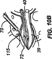
図1OAに、興味のあるレベルの中間線を横切るようなアプローチを用いて電極が神経根上膜(神経節外膜、nerve root epinurium)上又は内に埋込まれている脊髄の断面図を示す。
図10Bに、図10Aの埋込まれた電極の拡大図を示す。
FIG. 1OA shows a cross-sectional view of the spinal cord with electrodes implanted on or within the nerve root epinurium using an approach that crosses the midline of the level of interest.
FIG. 10B shows an enlarged view of the embedded electrode of FIG. 10A.
図11に、末梢神経に沿ったアプローチを用いる、他のDRG移植法を示す。 FIG. 11 shows another DRG transplant method using an approach along the peripheral nerve.
図12Aに、図12Bに図示された電極及びアンカーのデザインを用いた移植方法を示す。 FIG. 12A illustrates an implantation method using the electrode and anchor design illustrated in FIG. 12B.
図12Cに、周囲の椎骨を用いる、別の係留(アンカー)法を示す。 FIG. 12C shows another anchoring method using the surrounding vertebrae.
図13Aに、DRGに埋込まれた図13Bに図示されている単極性(モノポーラー)刺激コンポーネントの実施例(実施態様)を示す。 FIG. 13A shows an example (embodiment) of the unipolar (monopolar) stimulation component illustrated in FIG. 13B embedded in a DRG.
図14Aに、DRGに埋込まれた図14Bに図示されている双極性(バイポーラー)刺激コンポーネントの実施例(実施態様)を示す。 FIG. 14A shows an example embodiment of the bipolar stimulation component illustrated in FIG. 14B embedded in a DRG.
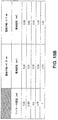
図15Aに、インピーデンスと電極表面積の関係を示す。 FIG. 15A shows the relationship between the impedance and the electrode surface area.
図15Bに、本発明の幾つかの実施例(実施態様)に係る刺激コンポーネントのための代表的な電極面積を示す。 FIG. 15B shows an exemplary electrode area for a stimulation component according to some embodiments (embodiments) of the present invention.
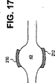
図16-20に、様々な実施例(実施態様)の電極を示す。 FIGS. 16-20 show electrodes of various examples (embodiments).
図20Aに、標的の神経組織に突刺し、固定するようにした電極を示す。 FIG. 20A shows an electrode that is pierced and fixed in a target nerve tissue.
図20Bに、図20Aの電極と一緒に使用するように適合された固定リングを示す。 FIG. 20B shows a fixation ring adapted for use with the electrode of FIG. 20A.
図20Cに、交感神経鎖内の神経節を刺激する位置に貫通電極がある実施例(実施態様)を示す。 FIG. 20C shows an embodiment (embodiment) in which there is a through electrode at a position for stimulating a ganglion in the sympathetic nerve chain.
図2ODに、貫通電極が後根神経節を刺激する位置にある実施例(実施態様)を示す。 FIG. 2OD shows an example (embodiment) where the penetrating electrode is in a position to stimulate the dorsal root ganglion.
図21に、DRGに埋込まれた、被覆電極を示す。 FIG. 21 shows the coated electrode embedded in the DRG.
図22に、種々の数の刺激機構の上流にあるDRGを示す。 FIG. 22 shows a DRG upstream of various numbers of stimulation mechanisms.
図23Aに、図23Bに図示されている閾値調節装置を提供するための、組合せ刺激及び剤デリバリー電極を示す。 FIG. 23A shows a combined stimulation and agent delivery electrode for providing the threshold adjustment device illustrated in FIG. 23B.
図23C及び23Dに、組合せた、刺激と薬剤デリバリー電極、及びシステムを示す。 FIGS. 23C and 23D show a combined stimulation and drug delivery electrode and system.
図24に、数種の薬剤及びその用途を示す。 FIG. 24 shows several types of drugs and their uses.
図25に、C−線維活性の軽減を目的とした、Naチャネル及びCaチャネル阻害を示す。 FIG. 25 shows Na channel and Ca channel inhibition for the purpose of reducing C-fiber activity.
図26に、パルス発生装置の模式図を示す。 FIG. 26 shows a schematic diagram of a pulse generator.
図27に、電極コネクタの一の実施例(実施態様)の模式図を示す。 FIG. 27 shows a schematic diagram of one embodiment (embodiment) of an electrode connector.
図28に、他の実施例(実施態様)のシングル(単一)パルス発生装置刺激システムを示す。 FIG. 28 shows another example (implementation) single pulse generator stimulation system.
図29に、マスター・スレイブアレンジメントを有する、別の実施例(実施態様)のマルチ(複数)パルス発生装置刺激システムを示す。 FIG. 29 illustrates another example multi-pulse generator stimulation system having a master slave arrangement.
図30に、脊髄レベルC1-C3の状態を治療するための刺激システムの実施態様を示す。 FIG. 30 illustrates an embodiment of a stimulation system for treating spinal level C1-C3 conditions.
図31A及び31Bに、それぞれ、閾値下のシグナルを閾値以上に増大させるために、本発明の実施例(実施態様)に従って刺激した結果を示す図である。 FIGS. 31A and 31B are diagrams showing the results of stimulation according to the example (embodiment) of the present invention in order to increase the signal below the threshold value to the threshold value or more, respectively.
図32に、交感神経系を示す。 FIG. 32 shows the sympathetic nervous system.
図33に、本発明の1実施例(実施態様)様の刺激系で神経調節(neuromodulate)された交感神経系の一部を示す。 FIG. 33 shows a part of a sympathetic nervous system that is neuromodulated with a stimulation system according to one embodiment (embodiment) of the present invention.
図34に、単一交感神経神経節と同脊髄レベルの単一後根神経節を直接刺激するために埋込まれた本発明の1つの実施例(実施態様)を示す。 FIG. 34 shows one embodiment (embodiment) of the present invention implanted to directly stimulate a single sympathetic ganglion and a single dorsal root ganglion at the same spinal level.
図35に、脊髄を直接刺激するために埋込まれた本発明の1つの実施例(実施態様)を示す。 FIG. 35 shows one embodiment (embodiment) of the present invention implanted to directly stimulate the spinal cord.
図36に、脊髄を直接刺激するために埋込まれた本発明の2つの実施例(実施態様)を示す。 FIG. 36 shows two embodiments (embodiments) of the present invention implanted to directly stimulate the spinal cord.
図37A-37Cに、脊髄に電極を埋込む際に用いたシーリング(密閉)の実施例(実施態様)を示す。 FIG. 37A-37C shows an example (embodiment) of sealing (sealing) used when an electrode is embedded in the spinal cord.
図38に、脊椎及び後根神経節の様々な部位に適用される、他の本発明の刺激システムの実施例(実施態様)をまとめて示す。 FIG. 38 collectively shows another example (embodiment) of the stimulation system of the present invention applied to various parts of the spine and dorsal root ganglia.
本発明は、直接及び特異的な神経刺激を可能にする、様々な実施態様の新規な刺激システムと方法を提供する。例えば、電極を神経根神経節に移植し、電極を活性化して神経根神経節を刺激することからなる、神経根神経節を刺激する方法を提供する。以下により詳細に説明するように、ある実施態様では神経根神経節は後根神経節であってよく、他の実施態様では神経根神経節は交感神経系、あるいは他の神経節又は他の組織の、神経根神経節であってよい。ある実施態様では、電極の移植(埋込)は神経根神経節の神経上膜(epinurium)を切開し、電極を開口部を通って神経節の内部空間又は束間空間に通すことを含む。 The present invention provides various embodiments of novel stimulation systems and methods that allow direct and specific neural stimulation. For example, a method of stimulating a radicular ganglion is provided, comprising implanting an electrode into a radicular ganglion and activating the electrode to stimulate the radicular ganglion. As will be described in more detail below, in some embodiments the ganglia may be dorsal root ganglia, and in other embodiments, the ganglia may be the sympathetic nervous system, or other ganglia or other tissues. It may be a radicular ganglion. In one embodiment, the implantation (implantation) of the electrode comprises incising the epinurium of the radiculone ganglion and passing the electrode through the opening into the internal or interbundle space of the ganglion.
別の実施態様では、活性な電極面を刺激エネルギーの神経節への送達に適切な位置に維持しつつ、電極本体の一部を神経節を完全に貫通させる。さらに本発明の他の実施態様に係る微少電極及び刺激システムでは、微少電極及び刺激パターンのサイズ、形及び位置を、標的神経組織を刺激し、他を除くよう選択する。他のさらなる実施態様では、電極刺激エネルギーを、標的組織又は領域を超えた場合、消散するか減じるように、標的神経組織に送達する。 In another embodiment, a portion of the electrode body is completely penetrated through the ganglion while maintaining the active electrode surface in place for delivery of stimulation energy to the ganglion. Furthermore, in a microelectrode and stimulation system according to another embodiment of the present invention, the size, shape and position of the microelectrode and stimulation pattern are selected to stimulate the target neural tissue and exclude others. In another further embodiment, electrode stimulation energy is delivered to the target neural tissue so that it dissipates or reduces when the target tissue or region is exceeded.
一度電極を所望の神経根神経節の上、内部又は隣接して(近辺に)配置すれば、活性化ステップは、プログラム可能な電気シグナルを電極にカップリングさせる(coupling)ことで進行する。1つの実施態様では、神経神経節に与えられる刺激エネルギー量は神経組織を選択的に刺激するのに充分である。特定の実施態様では、与えられた刺激エネルギーは標的DRG内の神経組織のみを刺激する。あるいはDRGを超える刺激エネルギーは近くの神経組織を刺激したり、調節したり又は影響を与えるのに十分なレベルより低い。 Once the electrode is placed on, within or adjacent to (in the vicinity of) the desired radicular ganglion, the activation step proceeds by coupling a programmable electrical signal to the electrode. In one embodiment, the amount of stimulation energy applied to the ganglion is sufficient to selectively stimulate neural tissue. In certain embodiments, the applied stimulation energy stimulates only neural tissue within the target DRG. Alternatively, the stimulation energy above the DRG is below a level sufficient to stimulate, regulate or influence nearby neural tissue.
電極が後根神経節に埋込まれた1つの例においては、無髄の直径が小さい線維(例えば、c−線維)よりも優先的に有髄の直径が大きい線維(例えばAβ及びAα線維)を活性化するように、刺激レベルを選択してもよい。さらなる実施態様では、神経組織を刺激するために電極を活性化するのに使われる刺激エネルギーは、神経組織を切断(ablate)、損傷さもなくば損傷させるために用いるエネルギーレベルより低く維持される。例えば、高周波経皮部分神経根切断の間、電極を後根神経節内に配置し、熱損傷が形成されるまで活性化し(即ち、電極チップ温度が約67℃)、対応する皮膚分節に部分的で一時的な感覚(知覚)喪失をもたらす。1つの実施態様では、DRGに与えられる刺激エネルギーレベルは、熱切断、RF切断又は他の神経根切断法の間に用いられるエネルギーレベルより低く維持される。 In one example where the electrode is implanted in the dorsal root ganglion, fibers that are preferentially larger in myelinated diameter (eg, Aβ and Aα fibers) than fibers that are smaller in unmyelinated diameter (eg, c-fiber) The stimulation level may be selected to activate. In a further embodiment, the stimulation energy used to activate the electrode to stimulate the neural tissue is maintained below the energy level used to ablate, otherwise damage the neural tissue. For example, during high-frequency percutaneous partial nerve root cutting, the electrode is placed in the dorsal root ganglion and activated until thermal damage is formed (i.e., the electrode tip temperature is approximately 67 ° C.) and partly in the corresponding skin segment. And temporary loss of sensation (perception). In one embodiment, the stimulation energy level applied to the DRG is maintained below the energy level used during thermal cutting, RF cutting or other nerve root cutting techniques.
組織刺激は、組織を通過する電流(current)が閾値に達したとき伝えられ(mediate)、この電流を受ける(経験する)細胞の脱分極を起こす。電流は、例えば、特定の表面積を有する2つの電極の間に電圧が与えられたとき生じる。刺激電極の極く近くにある電流密度は、重要なパラメーターである。例えば、電極面積1mm2を通過する1mAの電流は、その近傍に、電極面積10mm2を通過する10mAの電流と同じ電流密度(1mA/ mm2)を有する。この例では、電極表面に近接した細胞は同じ刺激電流を受ける。表面積に比例して、大きい電極は大量の細胞を刺激することができ、小さい電極は少量の細胞を刺激することができるという違いがある。
Tissue stimulation is mediate when the current through the tissue reaches a threshold, causing depolarization of the cell that receives (experiences) this current. The current is generated, for example, when a voltage is applied between two electrodes having a specific surface area. The current density in close proximity to the stimulation electrode is an important parameter. For example, 1 mA of current passing through the
多くの場合、好ましい効果は神経組織の刺激又は可逆的なブロックである。本明細書中「ブロック」又は「遮断(blockade)」は、神経インパルス伝達の中断、変調、及び阻害を意味する。異常な調節は、経路の興奮、経路阻害の喪失をもたらし、最終的な結果として、認知又は応答の増大を引き起こしうる。治療(処置)手段は、シグナル伝達の遮断又は阻害的なフィードバックの刺激のいずれかに向けたものであってよい。電気刺激は、標的神経構造へのそのような刺激を供給すると共に、等しく重要なこととして全神経系の破壊を阻止する。加えて、電気刺激パラメーターは、利点が最大であり副作用が最小になるよう調節することができる。 In many cases, the favorable effect is stimulation or reversible blocking of neural tissue. As used herein, “block” or “blockade” refers to the interruption, modulation, and inhibition of nerve impulse transmission. Abnormal regulation can result in pathway excitement, loss of pathway inhibition, and can ultimately result in increased cognition or response. The therapeutic means may be directed to either blocking signaling or stimulating an inhibitory feedback. Electrical stimulation provides such stimulation to the target neural structure and equally importantly prevents destruction of the entire nervous system. In addition, the electrical stimulation parameters can be adjusted to maximize benefits and minimize side effects.
図2Aは本発明の実施態様である、刺激系100を示しており、電極115が脊髄後根神経節40に移植されている。例示の目的で、神経後根42及び神経前根41が脊髄13に合する位置、それぞれ42H及び41Iと表示、を脊髄レベル14、脊髄の小区域(サブセクション)13を用いて示している。末梢神経44は神経後根42と神経後根神経節40、及び神経前根41に分割される。簡単にするため、神経は一つの側のみを図示し、他の側は通常の解剖学的構造を有する。脊髄硬膜層32は脊髄13を囲み、脳脊髄液(CSF) で満たされている。明確にするため、脊髄鼓膜層実質32のみを、3つの脊髄13を囲み保護している実質-軟膜、クモ膜、及び硬膜−を代表する言葉として用いる。
FIG. 2A shows a
電極115は、神経根が運動神経を含む神経前根41と、感覚神経を含む神経根後根42に分裂した後、末梢神経44の中央に埋込まれていることに注意されたい。電極115はまた、硬膜層32の側面に埋込まれている。本発明の、1以上の電極を好都合に配置することで、周囲の神経組織を刺激せず、選択的に神経組織(神経根神経節など)を刺激することができる。この例では、後根神経節40は、神経前根44の運動神経、脊髄13の部分、脊髄レベル14又は末梢神経44に供給された殆ど無いか微少な刺激エネルギー量で刺激される。本発明の実施態様は、痛みのコントロールを与えるのに最も適する。なぜなら、後根神経節40を通る感覚(知覚)線維を、特異的に標的としうるからである。有利な本発明の実施態様では、痛みをコントロールするために、他の組織には影響を及ぼさずに、1つ以上の神経後根神経節に対して神経調節(neuromodulate)を行う。
It should be noted that the
刺激システム100は、狭い面積で高いインピーダンスの微少電極を用いて神経組織を刺激するよう適合された、直接プログラム可能なパターンの刺激エネルギーを供給するパルス発生装置を含む。与えられる刺激レベルは、Aβ及びAα線維52が、c-線維54より優先的に刺激されるよう、選択する。本発明の実施態様で用いる刺激エネルギーレベルは、従来の非直接、非特異的刺激系よりも低い刺激エネルギーレベルを利用する。なぜなら、電極115が、有利に、後根神経節 40上、内、又は周囲に配置できるからである。従来のゲートコントロール理論に基づけば、より早い伝達Aβ及びAα線維52を、本発明の刺激法によって刺激することにより、線維52からのシグナル53が、アヘン製剤(opiates)を神経後根42と脊髄13の連結位置で放出される。この放出は連結部での応答閾値(限界)を上昇させる(上昇した閾値56)。後に到着するc-線維シグナル55は、高められた接合部閾値(junction threshold)56以下であり、検出されない。
The
従って、本発明のある実施態様では脊髄、末梢神経系、及び/又は1以上の神経根神経節の選択的な刺激を提供する。本明細書中、1つの実施態様として用いる場合、選択的刺激とは刺激が実質上神経根神経節のみを神経調節するか、神経刺激することを意味する。1つの実施態様では、後根神経節の選択的刺激は、運動神経は刺激しないか調節(変調)されないままである。加えて、他の実施態様では選択的刺激は、髄鞘内で、A-有髄線維が、c−無髄線維に比較して優先的に刺激されるか神経調節されることを意味する。かくして、本発明の実施態様ではA-線維がc−線維より迅速に(ほぼ2倍の速度で)神経インパルスを運ぶという事実を有利に利用する。幾つかの本発明の実施態様は、A−線維をc−線維よりも優先的に刺激することを意図した刺激レベルを与えるよう適合されている。 Accordingly, certain embodiments of the present invention provide selective stimulation of the spinal cord, peripheral nervous system, and / or one or more radicular ganglia. As used herein, as used in one embodiment, selective stimulation means that the stimulation substantially nerve modulates or nerve stimulates only the radicular ganglia. In one embodiment, selective stimulation of dorsal root ganglia remains unstimulated or unmodulated (modulated) in motor nerves. In addition, in other embodiments, selective stimulation means that within the myelin, A-myelinated fibers are preferentially stimulated or neuromodulated compared to c-myelinated fibers. Thus, embodiments of the present invention advantageously take advantage of the fact that A-fibers carry nerve impulses more quickly (almost twice as fast) as c-fibers. Some embodiments of the present invention are adapted to provide stimulation levels that are intended to stimulate A-fibers preferentially over c-fibers.
さらなる実施態様では、選択的な刺激はまた電極(薬剤で被覆されているか、それを運ぶように適合されている電極を含む。例えば、図21, 23 A, C 及び D)が、刺激の対象である組織又は他の神経系コンポーネントと密接に接していることを意味する。この側面は、本発明における有利な電極配置の利用に係る。以下に論ずる特定の例示の実施態様では、1つ以上の刺激電極を以下のように置く(1)神経根神経節の外側の鞘に対向してあるいは接して置く; (2)神経根神経節内に置く; (3)神経節束間空間内に置く;(4)脊髄部分と接する位置に置く;(5)硬膜外空間、硬膜、神経根上膜又は脊髄の一部を貫通するのに必要な位置に置く;(6)交感神経系の一部と接触する位置に置く(7)直接刺激の標的である神経組織と接触する位置に置く。 In a further embodiment, the selective stimulus also includes an electrode (including an electrode that is coated with or adapted to carry a drug. For example, FIGS. 21, 23 A, C, and D), the subject of the stimulus. Is in intimate contact with some tissue or other nervous system component. This aspect relates to the use of an advantageous electrode arrangement in the present invention. In certain exemplary embodiments discussed below, one or more stimulation electrodes are placed as follows: (1) placed against or in contact with the outer sheath of the radicular ganglion; (3) Place in the space between ganglion bundles; (4) Place in contact with the spinal cord part; (5) Penetration through epidural space, dura mater, supracervial or part of spinal cord (6) Place in contact with a part of the sympathetic nervous system. (7) Place in contact with nerve tissue that is the target of direct stimulation.
さらに、本明細書に記載の選択的刺激又は神経調節のコンセプトは数多くの異なる構造に適用可能である。片側だけ(一側性の)(又は1つのレベルの1つの神経根神経節)、両側性(同レベルの2つの神経根神経節上又は内)、ユニレベル(同レベルの1以上の神経根神経節)又はマルチレベル(2以上のレベル各々の1以上の神経根神経節が刺激される)又は、上記の組合せであり、交感神経系の一部及び交感神経系のその部位の神経活性又は伝達に関連した1つ以上の後根神経根の刺激を含む。かくして、本発明の実施態様は、個別の又は重複する(overlapping)治療範囲を創造し、与えるために、広範な様々な刺激制御法の作出に利用できる。 Furthermore, the selective stimulation or neuromodulation concept described herein is applicable to many different structures. Unilateral (unilateral) (or one level of one radicular ganglion), bilateral (on or in the same level of two radicular ganglia), unilevel (one level of one or more radicular nerves) Node) or multi-level (one or more radicular ganglia of each of two or more levels are stimulated) or a combination of the above, and the neural activity or transmission of a part of the sympathetic nervous system and that part of the sympathetic nervous system Including stimulation of one or more dorsal roots related to Thus, embodiments of the present invention can be used to create a wide variety of stimulus control methods to create and provide individual or overlapping treatment ranges.
図3Aは髄レベルの後根神経節 (DRG)40に埋込まれた電極115を有する刺激システム100を示している。図は脊髄13の3つの代表的な脊髄レベル14(脊髄レベル1−3)を示している。末梢神経44は、後根神経節40と神経前根41に流れ込み、それぞれが脊髄13に流れ込んでいる。後角37、36も図示されている。明瞭化のため、硬膜32と完全な脊髄13は図示していないが、本願の他の箇所に記載され、またヒトに解剖学的に存在すると同様、存在している。これらの例にあるレベル1、2及び3は脊髄13に沿って存在する。簡単にするために、各レベルは神経の一側面のみを示している。
FIG. 3A shows a
レベル2を参照すると、上行路92がレベル2とレベル1の間に記載されており、下行路94がレベル2とレベル3の間に記載されている。レベル2のDRG40への刺激エネルギー又はシグナルの適用を、レベル2から路/経路92に向かうブロックシグナルの進行をブロックするのに用いることができる。さらに、レベル2部分への変調(modulation)適用は、効果的に他のレベル(ここでは、レベル1及び/又は3を用いる)からのニューロン路(neuron path)/経路が脳に至るのをブロックするのに有用であり得る。よって、同じく、本発明の1つの実施態様の装置及び/又は方法を用い、レベル2DRG 40に刺激を適用することで、有利に区内疼痛伝達経路をブロックしうる。3つの連続的なレベルについて例示したが、本発明のある実施態様を用いて、隣接した2以上のレベルを刺激することができ、さらには、別の実施態様では、隣接していない2以上のレベル、あるいはそれらの組合せを刺激することができることは理解されるであろう。
Referring to
図3Bはそれぞれの椎骨脊髄レベルを脊髄神経根に関係付けている。文字Cは、頸レベルの神経及び頸椎を指す。文字Tは胸レベルの胸椎及び神経を指す。文字Lは腰レベルの腰椎及び神経を指す。文字Sは仙骨レベルの仙椎及び神経を指す。図3Cは図3Bに記載した各神経根との関係で身体の様々な皮膚分節(デルマトーム)を示した図である。 FIG. 3B relates each vertebral spinal level to the spinal nerve root. The letter C refers to the cervical nerve and cervical spine. The letter T refers to the thoracic vertebrae and nerves at the chest level. The letter L refers to the lumbar vertebrae and nerves at the lumbar level. The letter S refers to sacral vertebrae and nerves. FIG. 3C shows various skin segments (dermatomes) of the body in relation to the nerve roots described in FIG. 3B.
図4-7は、異なるレベル及び程度の痛みコントロールを与えるために、様々なコントロール条件下で活性化された神経系の1つの実施態様を示している。図4A、5A、6A及び7Aは全て、異なる活性化程度での刺激系を図示したものである。図4B、5B、6B及び7Bは対応する、影響された皮膚分節を図示したものである。 FIGS. 4-7 illustrate one embodiment of the nervous system activated under various control conditions to provide different levels and degrees of pain control. Figures 4A, 5A, 6A and 7A all illustrate stimulation systems with different degrees of activation. Figures 4B, 5B, 6B and 7B illustrate corresponding affected skin segments.
図4A、5A、6A及び7Aは2つの隣接する脊髄レベルの後根神経節40に埋込まれた3つの電極115を有する刺激システム100を図示したものである。簡単にするため、各脊髄レベルは後根神経節40、前根41及び末梢神経44を示している。例外は脊髄レベル3であり、追加的に後根神経節38、前根39及び末梢神経42を示している。3つの電極115は、コントローラ106によりチャネル1、2及び3に指定されている。各電極はコントローラ106の制御下、活性化されて調節エネルギー又はシグナルを供給する。神経根神経節に埋込まれる例示の電極は、図12A-13Bにさらに図示されている。レベル3は両側性電極配置の例でありレベル2は片(一)側性電極配置の例である。よって、例示の実施態様はマルチレベル、片側性、及び両側性刺激系である。刺激エネルギーはパルス発生装置(図示しないが、図26-29により詳細に記載されている)から、適当な神経刺激コントローラ106の制御下、与えられる。当業者は、広範な既知の神経刺激コントローラから任意のものを用いることができると認識するであろう。この点では例示していないが、このシステムには、種々の電極115、電極リード110及びコントローラ106間に適当な連結部が存在している。後述の図で、電極リード110をコントローラ106に連結する線(ライン)はコントローラ106から1つの電極115((図4A参照)又は1つ以上の電極115 (図5A参照) への伝達“刺激オン”を示す。
4A, 5A, 6A and 7A illustrate a
「刺激オン」というシグナルは、広範囲に及ぶ刺激のパターンや程度の任意のものを指す。「刺激オン」シグナルは連続的または間欠的に与えられる振動電気シグナルであってよい。さらに、電極が1つ以上の神経節内又はそれに隣接して直接移植される場合、振動電気シグナルは1つの電極に与え、他には与えなくてもよく、その逆の場合もある。刺激する極、パルスの幅、振幅、刺激頻度(振動数)、その他制御可能な電気的及びシグナル因子を適宜調整し、所望の転調又は刺激結果を得るようにすることができる。 The signal “stimulus on” refers to any of a wide range of stimulation patterns and degrees. The “stimulus on” signal may be an oscillating electrical signal applied continuously or intermittently. Furthermore, if the electrode is implanted directly in or adjacent to one or more ganglia, the oscillating electrical signal may be applied to one electrode and not to the other, and vice versa. The stimulation pole, pulse width, amplitude, stimulation frequency (frequency), and other controllable electrical and signal factors can be appropriately adjusted to obtain the desired modulation or stimulation result.
振動性電気シグナルの適用は、電極115が配置されている神経鎖面を刺激する。この刺激は神経活性を増大又は減少させる。次いで、生理的異常により現れている症候が証明可能に減じられるまで、この振動電気シグナルの振動数を調節する。このステップは患者からのフィードバック、センサー又は他の生理的なパラメータ又は指標を利用して行うことができる。一度同定されたなら、その振動数が、理想的な振動数と考えられる。理想的な振動数が決定されれば、その振動数をコントローラーに保存し、振動電気シグナルをこの理想的な振動数に維持する。
Application of an oscillating electrical signal stimulates the nerve chain surface on which the
1つの具体例では振動電気シグナルを約0.5V〜約20 Vの間、又はそれ以上の電圧で操作する。より好ましくは、振動電気シグナルは約1 V〜約30 V、さらには〜40Vの間の電圧で処理する。微少(マイクロ)刺激のためには、1V〜約20Vの間で刺激することが好ましいが、その範囲は、電極の表面積のような因子に依存する。電極シグナル源を約10 Hz〜約1000 Hzの間の振動数で操作することが好ましい。電極シグナル源を約30 Hz〜約500 Hzの間の振動数で操作することがより好ましい。振動電気シグナルのパルスの幅は約25マイクロ秒から約500マイクロ秒の間であることが好ましい。振動電気シグナルのパルスの幅は約50マイクロ秒から約500マイクロ秒の間であることがより好ましい。 In one embodiment, the oscillating electrical signal is operated at a voltage between about 0.5V and about 20V or higher. More preferably, the oscillating electrical signal is treated with a voltage between about 1 V and about 30 V, or even ˜40V. For microstimulation, it is preferred to stimulate between 1 V and about 20 V, but the range depends on factors such as the electrode surface area. It is preferred to operate the electrode signal source at a frequency between about 10 Hz and about 1000 Hz. More preferably, the electrode signal source is operated at a frequency between about 30 Hz and about 500 Hz. The pulse width of the oscillating electrical signal is preferably between about 25 microseconds and about 500 microseconds. More preferably, the pulse width of the oscillating electrical signal is between about 50 microseconds and about 500 microseconds.
振動電気シグナルの適用は以下の多くの異なる方法で得られる(これらに限定されない)。(1)単極刺激電極と大面積の非-刺激電極リターン電極;(2)数個の単極刺激電極と単一の大面積非-刺激電極リターン電極;(3)一対の密接した双曲(バイポーラー)電極;及び(4)数対の密接した双曲電極。他の構成も可能である。例えば、本発明の刺激電極(群)は、他の非刺激電極−リターン電極-と一緒に使用するか、又は刺激システムの一部がリターン電極の機能性を与えるよう適合させる、及び/又はそのように構成することができる。その一部がリターン電極の機能性を与えるよう適合され得る、及び/又は設定され得る刺激システムの部分には、限定されないが、バッテリーケーシング又はパルス発生装置ケーシングが含まれる。 Application of oscillating electrical signals can be obtained in many different ways, including but not limited to: (1) Unipolar stimulation electrode and large area non-stimulation electrode return electrode; (2) Several unipolar stimulation electrodes and single large area non-stimulation electrode return electrode; (3) A pair of intimate hyperbolic (Bipolar) electrodes; and (4) several pairs of closely spaced hyperbolic electrodes. Other configurations are possible. For example, the stimulation electrode (s) of the present invention may be used in conjunction with other non-stimulation electrodes—return electrodes—or adapted to provide a functionality of the return electrode and / or part of the stimulation system It can be constituted as follows. The portion of the stimulation system, some of which can be adapted and / or configured to provide return electrode functionality, includes, but is not limited to, a battery casing or a pulse generator casing.
図の設定(構成)では、レベル3に位置する電極の1(即ち、チャネル#1「オン」)1つに与えられた刺激パターンが、身体各領域(即ち、陰影をつけた領域R1)における痛みをブロック/解除(除去)したことが示されている(図4B)。
In the illustrated configuration (configuration), the stimulation pattern applied to one of the electrodes located at level 3 (ie,
本発明の実施態様によれば、特定の皮膚分節分布を刺激し、どの電極又は電極の組合せ (薬物−コーティング又は−デリバリー電極)が、1つ以上の特定の痛み領域と最も密接な位置であるか、関連するかを明らかにすることができる。そのようにして、本発明の実施態様に係る刺激系は特定の痛みの範囲又は型につき「微調整された"fine tuned"」ものである。そのような試験で得られる結果は、特定のパテント(patent)あるいは特定のタイプの痛みのための1つ以上の刺激又は治療レジメ(即ち、被覆された電極からの治療薬の存在下、またはそれと組み合わせた一連の刺激)に用いることができる。これらの痛みの治療レジメは適当な電気的コントローラかコンピュータ制御システム(下記)にプログラムして、所望の治療レジメが遂行されたとき、刺激レジメのシステムコンポーネントの遂行を制御し、監視するよう治療プログラムを保存する。 According to embodiments of the present invention, a specific skin segment distribution is stimulated, and which electrode or combination of electrodes (drug-coating or delivery electrode) is in closest proximity to one or more specific pain areas Or relevant. As such, the stimulation system according to embodiments of the present invention is “fine tuned” for a particular pain range or type. The results obtained in such a test are the result of one or more stimulation or treatment regimens for a specific patent or a specific type of pain (ie, in the presence of, or with, a therapeutic agent from a coated electrode). A series of combined stimuli). These pain treatment regimes can be programmed into an appropriate electrical controller or computer control system (below) to control and monitor the performance of the system components of the stimulation regime when the desired treatment regime is achieved. Save.
図5Aは、他の例であって、マルチチャンネル刺激システムと方法を使用した痛み除去の分布の例を示す。図の構成と刺激パターンにおいて、刺激パターンはレベル2と3にある各電極にチャネル#1と#2から与えられる。この刺激電極パターンは痛みのブロック/除去を身体の指摘領域 (即ち領域Rl、R2)に与える(図5B)。
FIG. 5A shows another example of a pain relief distribution using a multi-channel stimulation system and method. In the configuration and stimulation pattern shown in the figure, the stimulation pattern is applied to the electrodes at
図6Aは、他の例であって、マルチチャンネル刺激システムと方法を使用した痛み除去の分布の例を示す。図の構成と刺激パターンにおいて、刺激パターンはレベル3にある両電極にチャネル#1と#3から与えられる。この刺激電極パターンは痛みのブロック/除去を身体の指摘領域 (即ち領域R3)に与える(図6B)。
FIG. 6A shows another example of a pain relief distribution using a multi-channel stimulation system and method. In the illustrated configuration and stimulation pattern, the stimulation pattern is applied to both electrodes at
図7Aは、他の例であって、マルチチャンネル刺激システムと方法を使用した痛み除去の分布の例を示す。図の構成と刺激パターンにおいて、刺激パターンは、チャネル#1、#2及び#3からシステムの全電極に与えられる。この刺激電極パターンは痛みのブロック/除去を身体の指摘領域 (即ち領域R4)に与える(図7B)。図4A-7Bに図示した電極の配置とブロック領域パターンは、個々の必要性に応じ、例えば、図3Bや3Cに記載した身体の特定の部分を標的とする配置に関する情報を用いて改変しうることは理解できるであろう。
FIG. 7A shows another example of a pain relief distribution using a multi-channel stimulation system and method. In the illustrated configuration and stimulation pattern, the stimulation pattern is applied to all electrodes of the system from
本発明の微少電極(マイクロ電極)と刺激システムに関する実施態様は、本発明の移植法を用いて単独の神経根神経節に埋込みが可能である。本明細書に記載した移植法は以下のような(これらに限定されないが)多くの利点を有する。他の方法と同様、低リスクの経皮アクセス経路、薬剤被覆電極を用いた場合は神経根への薬剤の限定的な量の直接送達、及び優先的、選択的な神経線維刺激を可能にする電極配置。 Embodiments relating to the microelectrodes and stimulation systems of the present invention can be implanted in a single radicular ganglion using the transplantation method of the present invention. The transplantation methods described herein have many advantages, including but not limited to: Like other methods, it allows low-risk transdermal access routes, limited delivery of drugs directly to nerve roots when using drug-coated electrodes, and preferential and selective nerve fiber stimulation Electrode arrangement.
図8Aはある脊髄レベルの断面図である。末梢神経44、42は後根神経節40、38と神経前根41, 39に、それぞれ、に流入している。椎体70と2つの交感神経神経節62、63も図示さている。この実施態様の方法は、適当なカテーテル107を内側に、椎体 70に向けて末梢神経42 に沿って、後根神経節38に前進させることを含む。カテーテル107は蛍光透視法や他の適当な医学的イメージング法などの外部の画像診断法をガイダンスとして用いて進める。椎孔は 蛍光透視法で観察しうるよい目印であり、DRG38の位置決めに有用である。
FIG. 8A is a cross-sectional view at a spinal level.
電極115は、後根神経節上膜に開口部を形成し、その開口部を通過して後根神経節の近位に移植されている。(図8 A、8B)。開口部は、カテーテル107の端、その先端に付けたチップ、カテーテル107内をワーキングチャネルで進む装置を用いる切断か、あるいは他の適当な内視鏡的又は侵襲性が最小の外科的方法で形成することができる。あるいは、電極本体又は遠位端に組織切断又は貫通(ピアス、cuttiing or piercing)装置を付け、組織への貫通を助けることができる(例えば、図20Aのチップ908参照)。カテーテル107を除去すると微少電極リード110が展開し、DRG 38に隣接した組織、生体構造又は骨に付着するか、係留(アンカー)するか固定され、電極115がDRG38から引き抜かれる可能性を減少する。下記の別法では、微少電極リード110を、電極の移植前に神経根神経節に固定化しておく。
The
電極115は、DRG 38内にフィットするようにサイズと形を整えておくよう注意すべきである。典型的なDRGは、一般に球形(直径3-5mm)である。もちろん、ヒトにおけるDRGのサイズ範囲は、個体の年齢、性及び他のファクターに依存して様々である。電極の実施態様は、患者の具体的な解剖学的特徴に合わせたサイズ範囲で提供される。個人に対する適当なDRG電極態様の使用に際しては数多くのファクターを考慮する。
Care should be taken that the
DRG内における電極配置は、本明細書に記載の方法やシステムに適合させた体感覚性誘発電位(SSEP)のような神経診断テスト法や筋電図法(EMG)により、確認することができる。1つの例として、移植された電極(1又はそれ以上)を有するDRGレベルの上又は下の、感覚神経系内に感覚電極を配置する方法がある。電極を標的DRG内に移植する。テスト刺激をDRGに適用し、標的DRGの上及び下の感覚電極における電位を測定し、電極が標的 DRGに移植されていることを確認する。テスト刺激は0.4 v〜0.8v、50Hzか、用いた誘発電位測定法に応じて他の適当な刺激レベルである。この方法で、従来の蛍光透視法及び 装置を用いて、電極をDRG に向けて進め、内部に移植し、電極が正しく移植されたことを確認し、標的DRGを刺激することができる。 Electrode placement in the DRG can be confirmed by neurodiagnostic test methods such as somatosensory evoked potentials (SSEP) and electromyography (EMG) adapted to the methods and systems described herein. One example is a method of placing sensory electrodes in the sensory nervous system above or below the DRG level with implanted electrode (s). Implant electrodes into the target DRG. A test stimulus is applied to the DRG and the potentials at the sensor electrodes above and below the target DRG are measured to confirm that the electrodes have been implanted into the target DRG. The test stimulus is 0.4 v to 0.8 v, 50 Hz, or other suitable stimulus level depending on the evoked potential measurement method used. In this way, using conventional fluoroscopy and equipment, the electrode can be advanced towards the DRG, implanted inside, confirmed that the electrode has been implanted correctly, and stimulates the target DRG.
DRG上、内、及び近くの位置に電極を操作するには、多種多様の方法が利用可能である。幾つかの方法を図8-10の脊髄馬尾部位の断面図に示した。これらの例では電極115はそれぞれの仙骨レベルの脊髄にある神経節の上又は内部に配されている。交感神経系神経節62、63も示されている。DRG 40と前根41は、末梢神経44に関連している。DRG38と前根39は末梢神経42と関連している。
A wide variety of methods are available for manipulating the electrodes on, within and near the DRG. Several methods are shown in the cross-sectional view of the spinal cord tail in FIG. 8-10. In these examples, the
図8A及び8Bは適当なカテーテル107を用いた、DRG38への側面からのアプローチを示す図である。カテーテルは末梢神経42に隣接し、DRG 38に向けて内側へ進んでいる。DRG硬膜は側面でピアス(貫通)されており電極115は、DRG内側へ進む。その後、電極115はDRG内部に移植される。次に、図8Bでは、カテーテル107がDRG38から引き出され、電極リード110が展開している。電極リード110は椎体70に、適当な固定化法で係留(アンカー)される。次いで、リード110をパルス発生装置/コントローラに連結する(図示せず)。
FIGS. 8A and 8B show a side view approach to
図9Aは、図8A及び8Bの解剖学的に同様の図である。図9Aは、興味のあるDRGより下方の中間線を横切る、別のDRG移植法を示している。カテーテル107は、蛍光透視ガイダンスの下、孔に向かい上方の経路を前進し、孔を用いてDRG内に入る。図9A及び9Bに示すように電極を後根神経節に移植することにより、後根神経節刺激法が提供される。ある実施態様の移植法は、電極部分を脊髄硬膜外空間を通って通過させることを含む。本発明のシステムにおける、神経根上膜72の上又は内部に配置された電極(図1OA及び10B)又は神経根の内部(即ち、図9A、B)にある。さらに、ある実施態様では、後根神経節上膜72に開口部を設け、電極をその開口部を通す(図9B参照)。
FIG. 9A is an anatomically similar view of FIGS. 8A and 8B. FIG. 9A shows another DRG transplantation method that crosses the middle line below the DRG of interest.
図11は、もう1つの別の電極移植法にかかる脊髄13の断面図である。外部からDRGに接近し、DRG外膜72を貫通し内部に入る上記の方法とは対照的に、図11は末梢神経44の神経鞘内から、DRG 内側(interlascular)への接近法を例示する。図11は、部分的に切除し下方の神経束46を示した、神経鞘の断面図である。この例示の例では、開口部がDRG40の側面のポイント45の末梢神経44鞘に作成されている。微少電極115は神経44鞘に開口部45から、適当な内視鏡又は侵襲性が最小の外科的な方法で挿入される。次いで、電極115をDRG 40内部に進行させる。
FIG. 11 is a cross-sectional view of the
これらの例示の各実施態様から明らかなようにDRGに関連して電極を配置することにより電極を活性化し、選択的に感覚神経を刺激することが可能になる。加えて、本発明方法により電極を配置することにより電極を活性化し感覚神経を、DRG内で、又は近辺の前根内の運動神経を刺激することなく、刺激することができる。本明細書に記載したコントロールシステムは、無髄線維より優先的に有髄線維を刺激するようなレベルで刺激するように電極を活性化する、刺激レベルを提供する。 As is apparent from each of these exemplary embodiments, placement of the electrode in relation to the DRG activates the electrode and can selectively stimulate sensory nerves. In addition, by placing the electrodes according to the method of the present invention, the electrodes can be activated and sensory nerves can be stimulated in the DRG or without stimulating motor nerves in the nearby anterior root. The control system described herein provides a stimulation level that activates the electrode to stimulate myelinated fibers preferentially over unmyelinated fibers.
さらに、以下により詳細に記載するように、図11は刺激治療を補助するために、又は他の治療上の利益を得るために、電極チップとシャフトが薬剤で被覆されていてもよい電極の実施態様を示している。図示するように、電極はチップコーティング130及びシャフトコーティング132を含む。各コーティング130、132は同一でも異なっていても良い。神経鞘を通して移植することの1つの利点は、被覆されたシャフトを好都合に前根41に近接して配置できるので、被覆シャフト132が神経前根41内で活性であるか、その神経活性に有益な薬剤を含有することができるということである。シャフトコーティング132は、神経鞘内の圧力に起因する炎症又はイリテイションを減少するよう選択することができる。
Further, as described in more detail below, FIG. 11 illustrates an implementation of an electrode in which the electrode tip and shaft may be coated with a drug to assist stimulation therapy or to obtain other therapeutic benefits. An embodiment is shown. As shown, the electrode includes a
図12A及び12Bは、電極115がDRG40に移植された後リード110を固定するための固定用フック172を有するアンカー体171の一例を示す。図12Aは脊髄13の一部の断面図であって、後根42、前根41、DRG40及び末梢神経44を示している。この例示の実施態様において、カテーテル70を、電極115、リード110及びアンカー171をDRG 40移植部位に関して操作するのに使っている。適当な部位が同定されれば、フック172をDRGの筋膜層に挿入する。フック172は、種々の形であってよく、外側DRG層又は外側DRG層内に、係合して固定するのに適した輪郭にする。図12Bはカテーテル70の遠位に取付けたアンカー体171とアンカーフック172の例を示す図である。カテーテル70を単独で、又は他の適当な外科的内視鏡又は最小限の侵襲性ツールと組み合わせてアンカー体171とフック172を操作することができる。同様にして、電極115、リード110を標的神経組織の上、中又は周辺に移動させることができる。他の電極の実施態様では 電極115のDRG上、中又は周辺への移植は、慢性的な摩擦と潰瘍形成を防止又は緩和するのに有用な柔軟性のある(flexible)チップを用いて行うことができる。
12A and 12B show an example of an
あるいは、電極リード110又は他の支持構造あるいはアンカー構造を、隣接する骨構造、軟組織又は、別の周辺解剖学的構造に取付てもよい。加えて、リード110の近辺での動きを吸収し電極が移植部位から引き抜かれたり、除去されないようにする、固定化、係留又は結合構造を電極アンカー172の近辺位置に設けてもよい。係留及び他の緊張機構の目的は、電極を移植部位内の位置に維持するか、電極リード110の動きによりその位置から移動しないようにすることである(即ちリード110の動きは電極115は移植部位から引っ張るか電極の移植部位での位置を乱す)。電極の配置には様々な方法が利用可能であることは理解できることであり、そのような方法には、シングル(単数)/マルチ(複数)フック又はアンカーの経皮配置、脊椎アンカー又はポスト(柱)、微少縫合糸、セメント、ボンド、及び当該技術分野の当業者が既知の他の連結又は係留法が含まれる。また、本明細書に記載した刺激システムの実施態様における他のコンポーネントも、刺激部位の近位、又は電極移植部位近くに装着するのに適合し得ることは理解されるだろう。他のコンポーネントとして、例えば、刺激コントローラ、マスターコントローラ、スレーブコントローラ、パルス発生装置、薬剤貯蔵所、薬剤ポンプ及びバッテリーなどを挙げることができる。
Alternatively, the
図12Cは電極リード110を電極移植部位を囲む骨組織に係留(アンカー)した例を示す。図12Cは脊髄13の部分の断面図であり、前根41、後根42及び後根神経節40を示す。図12Cはまた錐体周囲の骨を図示しており、椎体1110、棘突起1115、茎(pedicle)1120、薄膜1125、椎弓1130、横突起1135及び椎間(facet)1140などが示されている。電極115はDRG40に移植されており、電極リードは適当なアンカー111で位置に固定されている。アンカー111は、脊椎の骨性部分への任意の適当な固定化を表しており、それには、画鋲、ステープル、釘、セメント、外科又は整形外科の分野の当業者に既知の他の固定化手段が含まれる。張力緩和(緊張緩和)122はアンカー111とDRG40の間に存在する(図13A及び14A参照)。張力緩和122はDRG40内で電極115を動したり、DRG40から電極115を除去しうる動きを吸収するために使用する。この例示の実施態様では、張力緩和122は電極リード110のコイル状部分である。1つ以上の張力緩和122をアンカー111とDRG40の間、又はアンカー111と刺激システムのバッテリー又はコントローラ(図示せず)の間に配置することができる。
FIG. 12C shows an example in which the
図13A-14Bは本発明の単極又は双極刺激コンポーネントの実施態様を示す。図13Aは単極パルス発生装置に連結するように適合された近位コネクタ126Aを有する単極刺激コンポーネントを示している。遠位電極115は刺激部位で体内に移植されるよう形成されている。遠位電極は単極電極115A(図13B)又は双極電極115B(図14B)であってよい。電極のサイズは神経根神経節に移植するような大きさであり、選択された神経根により異なる。追加の実施態様では電極リードと電極は神経鞘内を神経根神経節に向けて進むのに適合され、大きさを選択されている。電極又はそれらのケーシングは免疫応答を引き起こす危険性(機会)を減ずるために無害な材料(シリコン、金属又はプラスチック)により形成される。電極は、MRI及び他の走査法(本明細書中に記載のラジオーオパーク(radio-oopaque)材料を用いる装置を含む)に適するものとすべきである。
13A-14B show an embodiment of a monopolar or bipolar stimulation component of the present invention. FIG. 13A shows a monopolar stimulation component having a
図13Aに戻ると、電気リード110は近位コネクタ126Aと遠位電極115を連結している。張力緩和機構122は刺激部位近くに連結されている。図示した張力緩和機構は電気リード110をコイル状にして形成されたものである。他の周知の張力緩和法と装置も使用しうる。固定化位置に近い電気リードの動き量を減少するよう適合された固定化エレメント124は、刺激部位の解剖学的構造の内部に、上に、又は通って配置される。本発明で用いる微少電極や微少リードは非常に小さく、1mm以下、多くの場合、0.5mm以下の極細く柔軟なワイヤを含んでいるので、微少リード110や微少電極115への張力や力の伝達を低下させるか最小にするためには複数エレメントが提供される。代表的な電極及びリードの大きさは以下により詳しく記載している(図15A、15B)。ある実施態様では張力と動きは固定化エレメント124、張力緩和122及び電極アンカー117 (もしあれば) により吸収されるか軽減される。固定化エレメント124は、例えば、ループ又は成形アイレット(小穴)であってよい。固定化エレメントは縫い込まれている、画鋲止め、ねじ止め、ステープル止め、粘着剤を用いて結合されているか、本明細書に記載の身体内にエレメントを確実に固定化するための当業者既知の他の方法を用いて連結されていて良い。
Returning to FIG. 13A,
1つの具体的な移植実施態様では、電極移植方法は、微少電極及び微少リードのサイズの小ささと繊細さを考慮して改変してよい。従って、最初は大きい力で作用した後、軽い力を作用する。このようにして、小さい微少電極と微小電極リード材料は、大きい力による操作の間は存在しない。本発明の電極をDRG内に移植する場合を例として考慮する。1つの例示の実施態様では、固定化エレメント124は、電極115を通過させるような大きさのループ状である。強い力で固定化エレメントを選択したDRG刺激部位に隣接した椎孔内に固定化エレメントを係留又はさもなくば固定化(即ち、接着) する。一般に固定化部位は、刺激部位に対して実際上、できるだけ近くする。1つの具体的な実施態様では固定化部位は、刺激部位から3cm〜5cmの位置である。場合により、ループに取り付けたガイドワイアは、位置に止まり電極とリードをループ、従って、移植部位に導くのに用いられる。電極とリードをループ(ガイドワイアを用いて、又は用いずに)に通す。次いで、電極をDRG上又は中に移植する。場合により、抗張力装置122は、移植部位内の電極と固定化エレメント124の間にする。1つの例示の実施態様では、複数のループを含有する微少電極リードの断面を抗張力装置122として用いる。最後に、微少電極リードを、適当なロック装置(locking device)を用いてループに固定化する。上記の方法は、単に1つの方法を例示したにすぎず、上記のステップは、使用した個別の移植方法に応じて様々な順番で実施するか、変更できることは理解できるであろう。
In one specific implantation embodiment, the electrode implantation method may be modified to take into account the small size and sensitivity of the microelectrodes and microleads. Therefore, after applying a large force at first, a light force is applied. In this way, small microelectrodes and microelectrode lead materials are not present during operation with large forces. Consider the case where the electrode of the present invention is implanted in a DRG as an example. In one exemplary embodiment,
幾つかの実施態様では、遠位電極115の近くにアンカー機構を供給することができる。アンカー機構としては、例えば、図13B及び14Bに記載のアンカー117が挙げられる。さらに他の実施態様ではアンカー機構は遠位電極115を刺激部位内に係留するよう適合される。例えば、 アンカー機構は移植の間、電極体118に対して平らに配する(詰める)、次いで神経根神経節から神経根神経節内に配備し、神経根壁内に係留し、電極を支持し電極の移動又は引き抜きを防ぐ。ある実施態様では、アンカー機構と遠位電極を一体的に形成し、他の実施態様では別々のコンポーネントである。ある実施態様では、アンカー機構はポリマー又はシリコンで形成される。
In some embodiments, an anchoring mechanism can be provided near the
選択的神経刺激には、より小さい電極も使用できる。小さい電極ほど衝撃が少なく望ましくない動きを受けにくいと考えられる。しかしながら、電極表面積が小さくなるほど、電極のインピーダンスは増大する(図15A)。従って、ある電極態様は、従来の刺激電極より遙かに大きいインピーダンスを有する。1つの実施態様では、本発明の微小電極のインピーダンスは2500Ω以上である。このインピーダンスにおける相違は、本明細書に記載の微小電極を駆動するための、刺激システムの動作における要求、パルス発生装置等に衝撃を与える。 Smaller electrodes can also be used for selective nerve stimulation. Smaller electrodes are considered to be less susceptible to undesirable movement with less impact. However, the electrode impedance increases as the electrode surface area decreases (FIG. 15A). Thus, certain electrode embodiments have a much higher impedance than conventional stimulation electrodes. In one embodiment, the impedance of the microelectrode of the present invention is 2500Ω or more. This difference in impedance impacts the demands on the operation of the stimulation system, the pulse generator, etc., for driving the microelectrodes described herein.
遠位電極は、神経根神経節内に移植し直接刺激するのに適する広範な種々の構成、形、大きさのであってよい。例えば、遠位電極115はリード110に装着した導電性材料のリングであってよい。あるいは、遠位電極115は、電極リードの非絶縁性ループで形成することができる。ループ状の電極はリード110に連結しなければならないリングとは異なり、ループはリードで形成することができ連結が不要であるため、魅力的で、摩耗性が改善されている。さらに他の実施態様では、電極はリードの非絶縁部分であって良い。
The distal electrode may be in a wide variety of configurations, shapes, and sizes suitable for implantation and stimulation directly into the radicular ganglion. For example, the
構成に関係なく、本発明の電極は、例えば、後根神経節又は交感神経系の神経節のような神経節の中、上又は周囲に移植するのに適合させ、大きさが決められる。電極のサイズは移植方法及び標的神経節のサイズにより異なることは理解されるであろう。DRGの直径は3-5mmにすぎないので、DRG硬膜を通して移植される電極(即ち図9A)は、5 mm以下であってよい。一方、末梢神経鞘に沿って移植するよう適合された電極(即ち、図11)は、硬膜を通る電極より長くてよいが、神経鞘内を遠位に進んでDRGに到達しなければならないので、他の設計上の制約がある。本発明の電極態様の大きさは、例えば、移植部位の解剖学的大きさと同様、移植法に基づく移植部位の大きさに応じて改変することができることは、理解できるであろう。 Regardless of configuration, the electrodes of the present invention are adapted and sized for implantation in, on or around ganglia, such as dorsal root ganglia or sympathetic ganglia. It will be appreciated that the size of the electrode will depend on the implantation method and the size of the target ganglion. Since the diameter of the DRG is only 3-5 mm, the electrode implanted through the DRG dura mater (ie FIG. 9A) may be 5 mm or less. On the other hand, an electrode adapted to be implanted along the peripheral nerve sheath (ie, FIG. 11) may be longer than an electrode that passes through the dura mater, but must travel distally within the nerve sheath to reach the DRG So there are other design constraints. It will be appreciated that the size of the electrode aspect of the present invention can be modified depending on the size of the implantation site based on the implantation method, for example, as well as the anatomical size of the implantation site.
図15Bは、直径0.25mm〜1 mm、幅0.25mm 又は0.5 mmのワイヤで形成される電極表面積の例を示す。従って、本発明の実施態様は、0.5 mm2未満の遠位電極表面積を与える。他の実施態様では、遠位電極表面積は1mm2未満である。さらに他の実施態様では遠位電極表面積は3 mm2未満である。 FIG. 15B shows an example of an electrode surface area formed of wire having a diameter of 0.25 mm to 1 mm and a width of 0.25 mm or 0.5 mm. Accordingly, embodiments of the present invention provides a distal electrode surface area of less than 0.5 mm 2. In other embodiments, the distal electrode surface area is less than 1 mm 2 . In still other embodiments, the distal electrode surface area is less than 3 mm 2 .
本発明の電極のサイズは、幅約8mmで、長さ24〜60mmの従来のパドル(図1)とは対照的である。その結果、従来の刺激電極は電極表面積が本発明の電極態様大きい。従来の電極は、10−12ボルトのパルス発生装置を用いて発生される刺激シグナルで操作される、500〜1800Ωのオーダーのインピーダンスを有する考えられる。対照的に、本発明の刺激電極態様は、2kΩ又は約2500 Ωm、2kΩ〜lOkΩ又はそれ以上、さらにはlOkΩ〜20kΩの範囲のオーダーのインピーダンスさえ有する。以下により詳細に記載するように、本発明のあるパルス発生装置の実施態様では、従来の刺激システムを超える範囲のDC-DC変換により産生される電圧で操作する。 The size of the electrode of the present invention is in contrast to a conventional paddle (FIG. 1) that is about 8 mm wide and 24-60 mm long. As a result, the conventional stimulation electrode has a larger electrode surface area than that of the present invention. Conventional electrodes are considered to have an impedance on the order of 500-1800 ohms, operated with a stimulus signal generated using a 10-12 volt pulse generator. In contrast, the stimulation electrode embodiments of the present invention have an impedance on the order of 2 kΩ or about 2500 Ωm, 2 kΩ to lOkΩ or more, and even lOkΩ to 20 kΩ. As will be described in more detail below, certain pulse generator embodiments of the present invention operate with voltages produced by DC-DC conversion in a range that exceeds conventional stimulation systems.
電極は柔軟で、長期使用の間、材料破壊がなく疲労特性に優れた材料から作られる。電極材料は、生体適合性(バイオコンパチブル)材料又はさもなくば生体適合性が改善されるように被覆または処理されるべきである。加えて、電極材料は、移植ステップ(段階)の間に電極を配置するのに使用される蛍光透視法のようなイメージングシステムに対して不透明である必要がある。適当な材料の例には、Pt、Au、NiTi、PtIr及び合金、並びにその組合せを挙げることができるが、これらに限定されない。電極は、移植又は刺激部位での炎症を避けるためにステロイドイルーディングコーティング(steroid eluding coating)をしてもよい。 The electrode is flexible and is made from a material with excellent fatigue properties without material failure during long-term use. The electrode material should be coated or treated to improve biocompatibility or otherwise biocompatibility. In addition, the electrode material needs to be opaque to an imaging system such as fluoroscopy used to place the electrode during the implantation step. Examples of suitable materials can include, but are not limited to, Pt, Au, NiTi, PtIr and alloys, and combinations thereof. The electrode may have a steroid eluding coating to avoid inflammation at the implantation or stimulation site.
小さい表面積を使用するので、低い電流で高電流密度を達成でき、DRGの刺激に必要な全エネルギーが劇的に減少される。微少電極を用いる1つの利点は、電極のごく周辺の僅かな量の組織しか刺激されないということである。微小電極使用に係るもう1つの利点は、バッテリサイズが減少されるので、対応するパルス発生装置も小さくなることである。 Since a small surface area is used, a high current density can be achieved at a low current, and the total energy required to stimulate the DRG is dramatically reduced. One advantage of using a microelectrode is that only a small amount of tissue in the immediate vicinity of the electrode is stimulated. Another advantage of using microelectrodes is that as the battery size is reduced, the corresponding pulse generator is also smaller.
上記の移植可能な電極に加えて、選択的に神経根神経節を刺激するための代替的な電極態様も使用可能である。図16は、導電性リング205、207が後根神経節40のいずれかの端に位置している例を示す 。活性化されると、リング205、206は容量的に合わさって刺激エネルギーをDRG40に供給する。図17は、容量性プレート210、212がDRG硬膜に結合した、他の容量性の刺激構成を図示している。本発明の実施態様は、一対の容量性プレートに限定されず、一対以上を使用することができる。図18は、DRG40の硬膜に結合した、2対の容量性プレートを示す。一対はプレート210、212を有し、他の対はプレート214ともう1つのプレートを有する(図示せず)。プレートを直接硬膜に結合させる別の方法では、プレートをDRG硬膜の周囲に滑り込ませ、それと関連させるよう適合させた電極サポートエレメント230に連結する。一度電極サポートエレメント230がDRGについて配置されれば、プレートは選択的にDRGを刺激するよう、適切に配置される。本発明は単に容量性にカップル(組み合わせた)刺激エネルギーに限定されない。図20は、ワイヤ235がDRG40の周囲に巻かれ、誘導的に刺激エネルギーを神経根神経節に供給するコイル236を作出する実施態様を示す。議論の目的で、これらの実施態様はDRGの刺激との関係で既述した。本明細書に記載した技術及び構造は、また、他の神経根神経節、他の神経構造又は他の解剖学的構造の刺激に用いることができることは理解できるであろう。
In addition to the implantable electrodes described above, alternative electrode embodiments for selectively stimulating the radicular ganglia can be used. FIG. 16 shows an example in which the
図2OA及び2OBは神経組織を通して移植するよう適合された他の電極の実施態様を示す。貫通電極900は、本体902、遠位末端904及び近位末端906を有する。電極表面又はコンポーネント912適当なリード914を介して、パルス発生装置/コントローラ(図示せず)からは刺激シグナルとエネルギーを受ける。遠位末端904は標的神経組織を貫通するよう適合されたチップ908を有する。さらに電極体902を標的神経組織に固定するため、1以上のアンカー910が遠位末端に設けられている。固定化リング920(図20B)は、電極本体902 を、標的神経組織に、又はそれに関連するよう設けられる。アンカー910は神経組織を通して挿入する間電極902に対して第一の、又は詰込んだ位置に置き、次いで、第2の、電極本体902からの展開位置に動かすことができる。展開位置(図20A、2OC及び20D)において、アンカー910は、電極900が神経組織から動くことを阻止する。多くの代替アンカー構造も可能である。アンカー910は円形パターンに配列された個々の柱(ストラット)であるか、それらの間に傘構造と同様の材質が存在するストラットであってよい、アンカー910はまた単独アンカーでも良い。
2OA and 2OB show other electrode embodiments adapted for implantation through neural tissue. The through
電極900は、標的神経組織を完全に通過し、電極912を標的神経組織部位内に位置させるよう適合した本体902を有する。この例示の実施態様では、次いで、電極本体902はDRG 40内(図20D)か交感神経鎖の神経節(図20C)内にぴったり合うように適合される。所望の刺激又は調節(変調)レベルを得るために、電極912は電極本体902のどの場所に位置しても良い。さらに電極912は電極912により生じる調節又は刺激エネルギーパターンが標的神経組織内に止まるか、その内部でのみ消散するように配置することができる。
固定リング920は電極本体902を標的神経組織内かそれに関連して配置するよう保持するために用いる。固定リング920は輪922を有するリング状である。ある実施態様では内側表面942は電極本体902を係合(engage)し保持するための摩擦係止表面として用いる。他の実施態様では内側表面942は電極本体を固定するよう表面処理されている。さらに他の実施態様では内側表面942は機械的に電極本体902を嵌め込み保持するように適合されている。固定リング920は電極本体902と標的神経組織の表面に固定され電極が引き抜かれたり移動するのを避けるために、適当な伸縮性又は非伸縮性の材料で形成されている、固定リング920は、リング920を電極本体902及び組織外層に接着するか機械的に付着させるよう生体適合性材料で形成されている。固定リング920は電極900を標的神経組織内に移植する間又はその後に存在させる。1つの別の実施態様では固定リング920はDRG外層に固定され、電極900上の係合特徴に係合する位置に相補的な係合構造(特徴)を有する。電極本体902は、固定リング輪922を通ってDRG40内に入り、相補的な係合構造が係合し、さらに電極本体902のDRG内でのさらに遠方への動きが止まるまで前進する。相補的な係合構造は電極900内のDRGや他の神経節などの神経組織への配置を助けるために、単独で、又はアンカー910と一緒に用いることができる。
The
図2OC及び2ODは脊髄13の断面図であり、標的神経組織を通して移植するよう適合した電極態様を示す。脊髄セクション14の様々な部位のさらなる詳細については図38に関連して後述する。これらの図には、末梢神経44と神経根41/42内における例示の感覚経路52/54と運動経路41Pと、脊髄への流入が図示されている。他の移植部位と刺激の代替法は米国特許6,871,099号に記載されており、それを引用して本明細書に組み込む。
2OC and 2OD are cross-sectional views of the
図2OCの例示の実施態様では、電極900は標的神経組織内の非中央位置にある。この実施態様では、標的神経組織は交感神経鎖990内の神経節992である。具体的な交感神経鎖内の標的神経組織の例は図32及び33に関連して後述する。電極912は電極本体902上、又は内に、電極本体902が神経節992を通過し固定リング920内に座すとき、電極912が神経節992の内部の所望の位置にあるように配置される。例えば、電極本体902の長さを変える、標的神経組織への挿入角度を変える、又は標的神経組織への初期挿入位置を変えることで、他の電極912を標的神経組織内に配置することも可能である。
In the exemplary embodiment of FIG. 2OC,
図2ODの例示の実施態様で電極900は標的神経組織の、概ね中央位置を維持するよう配置されている。この実施態様では 、標的神経組織はDRG40である。電極912は、電極本体902が固定リング920に座し電極912がDRG40のほぼ真ん中又は中央に位置するように電極本体902上又は内に配置される。上と同様、固定リング920及びフラットアンカー911は電極900をDRG 40内の所望の位置に固定する。フラット又はフラップアンカー911は、アンカー910と同様の機能性を与える。アンカー911は曲ったアンカー910より、むしろフラットアンカーを有する。
In the exemplary embodiment of FIG. 2OD,
ある実施態様では刺激電極チップを薬剤で被覆する。図21に例示した実施態様ではコーティング130はDRG40内の電極の部分を覆っている。他の実施態様では所望の臨床上の成果を上げるよう電極のより少ないか多い部分、又は他の移植コンポーネントが適切に被覆される。図21はまた電極シャフト、又はDRG外部の電極の被覆130を示す。コーティング132は、コーティング130と同様又は別であってよい。例えばチップコーティング130は遠位コーティング(DRGを効果的に刺激するのを助ける剤を含有する)を有している。チップコーティング130は、電極周囲での線維性増殖を阻止する薬剤を含有するさらに近位コーティング部位(即ち、電極の硬膜貫通(ピアス)位置に近く)を有していて良い。さらなる実施態様ではシャフトコーティング132も、電極近くでの線維性増殖を阻止する剤を含有していて良い。さらに、シャフトコーティング132は、前根(即ち、図11の移植法)又は末梢神経鞘内の組織と相互作用する薬剤を提供するということに基づいて選択することができる。
In one embodiment, the stimulation electrode tip is coated with a drug. In the embodiment illustrated in FIG. 21, the
コーティングとして用いられる薬剤により得られる所望の臨床成果の例には、限定的ではないが、瘢痕組織の発展の減少、電極上の組織増殖や形成の阻止、抗炎症、チャネルブロック剤及びその組合せ又は、痛み、神経学的病変の治療に有用な他の既知の薬剤が挙げられる。他の実施態様では、薬剤は体内に入ると、時間をかけて一定レベルの薬剤を放出させるような他の化合物を含有していても良い(即ち、時間放出薬剤)。ある実施態様では、薬剤 は抗炎症剤、鎮痛剤、COX阻害剤、PGE2阻害剤、それらの組合せ及び/又は術後の病理学的な疼痛変化を阻止するのに適した他の薬剤である。その他の使用可能な適当な薬剤は、 心内リード(cardiac leads)の被覆に使用されるものであり、ステロイドイルーディング心臓内リード又は他の移植可能な装置を被覆するのに用いられる他の剤である。 Examples of desired clinical outcomes obtained with agents used as coatings include, but are not limited to, reduced scar tissue development, inhibition of tissue growth and formation on electrodes, anti-inflammatory, channel blocking agents and combinations thereof or Other known agents useful for the treatment of pain, neurological lesions. In other embodiments, the drug may contain other compounds that release a certain level of drug over time when it enters the body (ie, a time-release drug). In certain embodiments, the agent is an anti-inflammatory agent, analgesic agent, COX inhibitor, PGE2 inhibitor, combinations thereof and / or other agents suitable for preventing post-operative pathological pain changes. Other suitable agents that can be used are those used to coat the cardiac leads and other agents used to coat the steroid illuminating intracardiac leads or other implantable devices. It is.
本発明の実施態様は、刺激を与えるのに用いる電極から薬剤を放出しながら神経根神経節又は他の神経学的構造を直接刺激することを含む。1つの実施態様では、薬剤は、電極を活性化する前に放出される。他の実施態様では薬剤は電極活性後、又は活性中に放出される。さらに他の実施態様では薬剤は神経根神経節を刺激している間、神経根神経節内で薬理学的に活性である。本発明の実施態様は、刺激される神経コンポーネントの具体的な必要性に適合させるよう改変及び修飾されることは理解できるであろう。例えば、本発明の実施態様は、適当な薬剤、薬剤放出パターン及び量、並びに刺激パターン及びレベルを用いて後根神経節又は交感神経系の神経根神経節を直接刺激するのに使用される。 Embodiments of the invention include directly stimulating the radicular ganglia or other neurological structures while releasing the drug from the electrode used to provide the stimulus. In one embodiment, the drug is released before activating the electrode. In other embodiments, the drug is released after or during electrode activation. In yet another embodiment, the agent is pharmacologically active within the radicular ganglion while stimulating the radicular ganglion. It will be appreciated that embodiments of the invention may be altered and modified to suit the specific needs of the neural component being stimulated. For example, embodiments of the present invention are used to directly stimulate dorsal root ganglia or sympathetic nerve root ganglia with appropriate drugs, drug release patterns and amounts, and stimulation patterns and levels.
図22を参照すると、図は様々な刺激機構を示す。これらの様々な機構は痛みを強める(potentate)間、それらの各々は一次知覚性ニューロンに作用する。この細胞の一次モジュレーターは、その細胞体、DRG40である。本発明の1つの側面は、DRG40の神経系内での解剖学的配置をうまく利用し他の治療手段を補償することである。他の実施態様では本明細書に記載のDRG40刺激を一次知覚ニューロンに対して作用する物質と一緒に用いることである。示したように他のメカニズムは例示の組織損傷に対し、DRG細胞体40よりも近い。異なる方法で、DRG40は他の痛みメカニズムの上流(即ち脳/脊髄13により近く)であってもよい。このように、これは上流DRG刺激の、他の痛みシグナルをブロック及び/又は軽減するための方法に係るもう一つの例を示している。
Referring to FIG. 22, the figure shows various stimulation mechanisms. While these various mechanisms potentiate pain, each of them acts on primary sensory neurons. The primary modulator of this cell is its cell body, DRG40. One aspect of the present invention is to take advantage of the anatomical placement of DRG40 within the nervous system to compensate for other therapeutic measures. In another embodiment, the DRG40 stimulation described herein is used in conjunction with substances that act on primary sensory neurons. As shown, other mechanisms are closer to
電気生理学的研究は、プロスタグランディンE2(PGE2)(COX酵素により産生される)が、TTX-R Na+チャネルの活性化に必要な膜脱分極の程度を減じることにより部分的に、DRGニューロンの興奮性を増大すると示唆している。これはニューロンを同時発火させ個々がスパイキングしやすくする(より強い痛覚に翻訳される)。また、ここでは他のプロ-炎症剤(Vanilloid Receptor [VRl]に対するブラジキニン(Bradykinin)、カプサイチン(Capsaicin))が、TTX-R NA+チャネルに集中して影響するかを個別に示している。鎮痛作用部位もTTX-R Na+チャネル調節の上流にある。本発明の実施態様は、疼痛(痛み)経路と神経科学の側面を有利に利用し、電気刺激が薬剤と関連している(カップル)(電気刺激のみ、又は薬剤と一緒に) DRGニューロンの電気生理学的な興奮性を調節し刺激システムの効率を最適化している。 Electrophysiological studies have shown that prostaglandin E2 (PGE2) (produced by the COX enzyme), in part, by reducing the degree of membrane depolarization required for TTX-R Na + channel activation, Suggests increased excitability. This makes the neurons fire at the same time, making it easier for individuals to spiking (translated into a stronger pain sensation). Here, it is shown individually whether other pro-inflammatory agents (Bradykinin, Capsaicin against Vanilloid Receptor [VRl]) concentrate on the TTX-RNA + channel. The site of analgesia is also upstream of TTX-R Na + channel regulation. Embodiments of the present invention advantageously take advantage of the pain (pain) pathway and neuroscience aspects, and electrical stimulation is associated with the drug (couple) (electrical stimulation alone or with the drug) It regulates physiological excitability and optimizes the efficiency of the stimulation system.
種々の投与経路を利用する多くの他の利用可能な薬理学的遮断薬や他の治療薬を、特異的、直接的な神経根神経節、後根神経節、脊髄又は末梢神経系の刺激と組み合わせて用いることにより、電気的調節と薬理学的調節の相乗効果(相互作用)を得ることが可能である。薬理学的遮断薬としては、例えば、Na+チャネルブロッカー、Ca++チャネルブロッカー、NMDAレセプターブロッカー、及びオピオイド鎮痛薬(opoid analgesics)を挙げることができる。図23A及び23Bは、刺激及び薬剤デリバリーを組み合わせた電極を示す。先端の双極電極115Bと、移植の間、硬膜を貫通するために先端の形が斜めになったコーティング130に着目されたい。電極チップはDRG上膜72内にあり、c-線維55応答を調節及び/又は影響するのに良い位置にある。図では丸はNa+イオンを、黒三角はNa+チャネルブロッカー(例えばダイランチン-[フェニトイン]、テグレトール-[カルバマゼピン]又は他の既知のNa+チャネルブロッカー)を表す。コーティング130から薬剤が放出されると、c-線維55上のレセプターがブロックされ、応答閾値以下のc-ファイバーの応答がブロックされる(図23B)。c-線維 の応答が低下すると、より直径が大きいA-線維が優先的に刺激されるか、A-線維の応答が図22Bの閾値以上になる。
Many other available pharmacological blockers and other therapeutic agents that utilize different routes of administration include specific, direct ganglia, dorsal root ganglia, spinal cord or peripheral nervous system stimulation. By using in combination, it is possible to obtain a synergistic effect (interaction) between electrical regulation and pharmacological regulation. Examples of pharmacological blockers include Na + channel blockers, Ca ++ channel blockers, NMDA receptor blockers, and opoid analgesics. Figures 23A and 23B show an electrode that combines stimulation and drug delivery. Note the tip
本発明はまた、多くの有利な併用両方の実施態様を提供する。例えば、電極115Bの刺激を減少するにもかかわらず一層の、臨床上有意な効果を達成するようなやり方で、薬剤が後根神経節内で作用するか、あるいは、後根神経節に影響するように、投与することができる。あるいは、刺激が与える効果が、薬剤不在時に比較してより増大するようなやり方で、薬剤が後根神経節内で作用するか、あるいは、後根神経節に影響するように、投与することができる。具体的な1つの実施態様として、薬剤導入後、c-線維レセプターが効果的にブロックされ、チャネル遮断薬の存在下で用いうるより高レベルの刺激が使用できるよう、チャネルブロッカーである。幾つかの実施態様では、薬剤は刺激前に放出される。他の実施態様では薬剤は刺激の間又は後に放出されるか、その組合せである。例えば治療法が提供される。薬剤を単独投与する、刺激を単独で与える、刺激を薬剤存在下で与える、あるいは刺激を薬剤投与後、刺激パターンの適用前に薬剤が所望の薬理効果を導入するのに十分な時間を設けるよう、薬剤投与後一定間隔をあけて刺激する、という治療方法が得られる。本発明の刺激システムと刺激パターンの実施態様により、薬剤コーティングと電気刺激を組み合わせた本発明の微小電極を用いてC-線維及びAβ-線維閾値の微調整ができる。代表的な薬剤として、限定的ではないがNa+チャネル阻害剤、フェニトイン(Phenytoin)、カルマバゼピン(Carbamazapine)、リドカイン(Lidocaine)GDNF、オピエート(アヘン製剤、Opiates)、バイコディン(Vicodin)、ウルトラム(Ultram)及びモルフィネ(Morphine)等がある。
The present invention also provides many advantageous combinations of both embodiments. For example, the drug acts in or affects the dorsal root ganglion in a manner that achieves a more clinically significant effect despite reducing the stimulation of
図23C及び23Dは神経刺激及び薬剤デリバリーシステムの組合せの他の実施態様を示す図である。これらの操作に適したコントローラ及びパルス発生装置の詳細を、図26〜29を参照して追加記述する。ポンプと貯留デリバリーシステム(reservoir delivery systems)の組合せを用いて説明するが、薬剤を貯蔵部から電極へ移動させるためのポンプ、デリバリー前に薬剤を貯蔵しておく貯蔵部は、協同(協調)的に操作される分離した2つのコンポーネントであってもよいことは理解できる。ポンプと貯蔵部は、送達すべき特定の薬剤の制御された送達に適した任意のものである。適当なポンプには、対象内への全移植に適合されており、痛みの処理のため、又はその他の本願明細書に記載の医薬のための製剤の送達に適した任意のものである。一般に、ポンプ及び貯蔵部は、操作可能に連結したポンプシステム、例えば浸透圧ポンプシステム、蒸気圧ポンプシステム、電気分解ポンプシステム、電気化学ポンプシステム、発泡ポンプシステム、圧電性ポンプシステム又は電気機械的ポンプシステムの作用により、貯蔵部(ポンプのハウジング、又はポンプと連通している分離容器により定義される)からの薬剤を移動させる移植可能な装置を意味する、薬剤デリバリー装置である。適当なポンプに関する詳細はUS特許第3,845,770号; 第3,916,899号;第4,298,003号及び第6,835,194号(その各々の全体を引用して本明細書に組み込む)から得ることができる。 FIGS. 23C and 23D illustrate another embodiment of a combination of neural stimulation and drug delivery system. Details of the controller and pulse generator suitable for these operations are additionally described with reference to FIGS. A combination of a pump and reservoir delivery systems will be described, but the pump that moves the drug from the reservoir to the electrode and the reservoir that stores the drug before delivery are cooperative. It can be appreciated that there may be two separate components operated on. The pump and reservoir are any suitable for controlled delivery of the particular drug to be delivered. Suitable pumps are any that are adapted for whole implantation into a subject and are suitable for the treatment of pain or other delivery of formulations for the medicaments described herein. Generally, the pump and reservoir are operably connected pump systems, such as osmotic pump systems, vapor pressure pump systems, electrolysis pump systems, electrochemical pump systems, foam pump systems, piezoelectric pump systems or electromechanical pumps. A drug delivery device, meaning an implantable device that moves drug from a reservoir (defined by a pump housing or a separation container in communication with the pump) by the action of the system. Details regarding suitable pumps can be obtained from US Pat. Nos. 3,845,770; 3,916,899; 4,298,003 and 6,835,194, each of which is incorporated herein by reference in its entirety.
図23Cは薬剤貯蔵部とポンプ195からの薬剤のデリバリーをコントロールするよう適合した、コントローラとパルス発生装置105Bを組み合わせたシステムを示す。薬剤貯蔵部及びポンプ195から押し出された薬剤は専用の導管を通り、共通供給部(common supply) 110F、張力緩和122Fを通り、薬剤及び刺激電極2310へ移動する。共通供給部11OFは、コントローラ105Bからの電極コントロール及びパワーシグナル、並びにポンプ195から送達された薬剤とを含有する単一の線又は2つの線が一緒になっているラインであってよい。構成とは無関係に、電極2310をコントローラ105Bとポンプ195とに連結するのに、単一の線が用いられるので、共通供給部110Fは、移植ステップを単純にする。
FIG. 23C shows a combined system of a controller and pulse generator 105B adapted to control drug delivery from the drug reservoir and pump 195. FIG. The drug pushed out from the drug reservoir and the pump 195 passes through a dedicated conduit, passes through a common supply 110F and a
神経刺激と薬剤デリバリー電極2310の組合せは、標的神経組織内に嵌合(フィット)するよう適合させた本体2312を含む。図示した実施態様では、電極本体2310は、DRG40内に嵌合するよう適合されている。電極2318は電極本体2312上又は内に位置するか、電極本体2312である。電極2318は、共通供給部110Fを介してパルス発生装置105Bから共通供給部110Fを介してシグナル及び出力(power)を受け取る。所望の刺激及び調節レベルを得るために、電極2318は電極本体2312上の任意の位置にあってよい。加えて、電極2318は、電極により発生される調節及び刺激エネルギーパターンが、標的神経組織内に止まるか、あるいはその中だけで蒸散するよう配置される。この例示の実施態様では、電極2318は、標的神経組織内の概ね中心部に止まるよう配置されている。この実施態様では標的神経組織はDRG40である。電極2318は電極本体2312上又は内に、電極2310が固定リング (以下に記載)内に座したとき電極2318がDRGのほぼ真ん中又は中心の真ん中にあるように置かれる。
The combination of neural stimulation and
固定リング2315は、電極本体2312を、DRG40の内部又はそれと関連して置くために用いる。固定リング2315は、適当な弾性又は非弾性材料で作成され、電極が引き抜かれるか外れるのを防止するよう、電極本体2312と外部DRG層に固定されていてよい。固定リング 2315はリング2315を電極本体902及びDRG外層に接着するか機械的に付着させるよう生体適合性材料で形成されていてもよい。固定リング2315は電極2310をDRGに移植する間又はその後に存在させる。1つの別の実施態様では固定リングはDRG外層に固定され、電極2310上の係合特徴に係合する位置に相補的な係合構造を有する。電極本体2312は、固定リング2315を通ってDRG40内に入り、相補的な係合構造が係合し、さらに電極本体2312のDRG内でのさらに遠方への動きが止まるまで前進する。相補的な係合構造はDRG内に配置するよう意図している電極2310がDRGを貫通するのを防ぐ。
The fixing
電極本体2312内には、共通供給部110Fの薬剤を含有する部位から遠位の開口部2316に伝達するための導管(conduit)又は管(lumen、図示せず)が、少なくとも1つある。操作に際しては、ポンプ/貯蔵部195内の薬剤(群)は、コントローラ105Bのコントロール下、共通供給部110Fから電極本体2312を通り、遠位開口部2316からDRG内側へとデリバーされる。遠位開口部2316の実施態様では移植する間DRGに穿刺するために使われる斜めの端を有することに注意されたい。
Within the electrode body 2312 is at least one conduit or tube (lumen, not shown) for communication from the site containing the drug in the common supply 110F to the
図23Dは神経刺激、薬剤デリバリーシステムと電極の組合せの他の幾つかの実施態様を示す。 FIG. 23D illustrates several other embodiments of neural stimulation, drug delivery system and electrode combinations.
コントローラ、パルス発生装置及びバッテリー105Bの組合わせを使用する図23Cと対照的に図23Dの構成(configuration)は図28及び29に記載されていると同様の分散型システムを提供する。パルス発生装置とコントローラ105C 及び薬剤貯蔵部とポンプ2395は、それぞれ、適当な連結2307及び2305を用いてバッテリー2830から電力を受け取る。薬剤貯蔵部とポンプ2395はコントローラ/発生装置105Cとは独立に操作される、それ自身のコントローラを有する、コントローラ/発生装置105C (即ちマスター/スレイブ関係で)のコントロール下で操作される自身のコントローラを有するか、コントローラ/発生装置105Cのコントロール下で操作され得る。電極912はリード110を介して発生装置105cから刺激パワーを受け取る。潅流ポート928は電極本体902内の1つ以上の導管(図示せず)を介して導管から薬剤 貯蔵部とポンプ 2395に連結されている。
In contrast to FIG. 23C, which uses a combination of controller, pulse generator and battery 105B, the configuration of FIG. 23D provides a distributed system similar to that described in FIGS. The pulse generator and controller 105C and the drug reservoir and pump 2395 receive power from the
電極900Aの実施態様は図20Aの電極900に似ている。電極900Aも電極本体902内の潅流ポート928を有し、それらは導管2396を介してポンプと貯蔵部2395内容物と連絡されている。電極本体902は標的神経組織を通して移植するに十分な長さを有する。図では、概ねDRG 40のほぼ中央に移植されているが、電極本体902は、異なるサイズの標的神経組織又は標的神経組織の異なる位置に移植するよう、より長く、あるいはより短くてもよいことは理解できるであろう。例えば図2OCは交感神経鎖の神経節内の非中心位置に移植された電極900を示している。電極900Aはチップ908とアンカー910を有する近位末端904を含む。固定リング920 (上記)は電極本体902をDRG 40に、またはそれに関連して固定するために提供される。アンカー910はDRGを通して挿入する間電極902に対して第一の、又は詰め込み位置に置き、次いで、第2の、電極本体902からの展開位置に動かすことができる。展開位置(図23D)において、アンカー910は、電極900AがDRG40から動くことを阻止する。多くの代替アンカー構造も可能である。アンカー910は円形パターンに配列された個々の柱(ストラット)であるか、それらの間に傘構造と同様の材質が存在するストラットであってよい、アンカー910はまた単独アンカーでも良い。
The embodiment of
電極912と潅流ポート928は電極本体902に沿って、神経刺激及び薬剤のデリバリーに適した任意の位置にあってよい。図示した実施態様では電極912はDRG内のほぼ中心にあり、潅流ポート928は電極本体902の遠位末端に位置する。他の構成も可能であり、より多数又は少数の電極及び潅流ポートを他の実施態様で用いることができる。例えば、潅流ポート 928はDRGの中心近くに位置させることができ、電極912はDRGを超えて、周辺組織へ入り込んで伝達される刺激エネルギーを最小限にするように、電極本体902のどこかに配置することができる。DRG 40又は他の標的神経組織内に刺激エネルギーが残存する(即ち、完全にその中で減衰する)よう、電極本体902に沿って1つ以上の電極912を位置させることができる。
1つの具体的な実施態様では、遠位チップ908は硬膜層を貫通、電極本体902をDRGに通すためのアクセスを作成するのに適した先端を有する。先端908はDRGを通りアンカー910がチップ908により形成された開口部を通り抜けるまで前進する(図23D)。一度アンカー910がDRGを通り先に伸びると電極本体902を少し引きアンカー910をDRG硬膜に係合させる。その後、固定リング920を電極本体902周辺まで、DRG40の外層に向けて進める。DRG 40内に移植されると、アンカー910と固定リング920を用いて電極900Aを配置させる。他の実施態様では、アンカー910なしに固定リング920を用いることができる。他の実施態様では、アンカー910を固定リング920を用いないか、固定リング920の代わりに、電極本体902をDRG内又はDRG近くに固定するよう適合された他のアンカーセットを用いる。
In one specific embodiment,
図24は、数種類の注入薬剤を示した表である。薬剤は左側にリストされている。右方向に、黒丸と白丸は、個々の薬剤を特定のタイプの痛み又は疾患に用いる上での、支持レベルを示している。黒丸は、対照臨床試験又は幾つかの非盲検による証明及び一般的な容認及び用途を示す。白丸は、広範でない証明によることを示す。例えば、下肢静止不能症候群(RLS)の治療には、ゼンゾジアゼピンは一般的な容認又は用途を有し、ガバペンチンはより少ない証明に基づいている。これらの、及び他の薬剤は身体に適用され、本発明の実施態様により、単独で、または本発明の実施態様により提供される刺激と組み合わせて、協同的に神経組織に薬理学的結果を与えることができる。幾つかの実施態様では、薬剤は刺激部位に提供され、他の実施態様では1つ以上の薬剤をでリバーするよう適合された刺激電極態様を用いて、薬剤は提供される。 FIG. 24 is a table showing several types of infused drugs. The drugs are listed on the left side. To the right, black and white circles indicate the level of support for using individual drugs for specific types of pain or disease. Black circles indicate control clinical trials or some open-label evidence and general acceptance and use. A white circle indicates that the proof is not extensive. For example, for the treatment of restless leg syndrome (RLS), zenzodiazepine has general acceptance or use, and gabapentin is based on less evidence. These and other drugs are applied to the body and, according to embodiments of the present invention, alone or in combination with stimuli provided by embodiments of the present invention, cooperatively provide pharmacological results to neural tissue be able to. In some embodiments, the drug is provided at the stimulation site, and in other embodiments, the drug is provided using a stimulation electrode embodiment adapted to river with one or more drugs.
以下の具体的な実施例を考慮されたい。侵害受容器(nociceptor)は特定の電位依存性ナトリウムチャネルサブクラスを発現する。これらのTTX-R Na+チャネル は、小直径感覚ニューロン(即ち、c-線維)内での作用ポテンシャル狙撃率と長さに有意に貢献していると考えられる。本発明の実施態様により、相乗的に神経刺激能力を改善するのに適当なチャネルブロッカーが提供される。例えば、薬剤とチャネルが直接接触するよう、刺激と薬剤放出の組合せをNaチャネル ブロッカーを後根神経節群束間空間内、c-線維に隣接して、又は薬理学的に活性な位置にに直接提供するのに使用できる。 Consider the following specific example. Nociceptors express specific voltage-gated sodium channel subclasses. These TTX-R Na + channels are thought to contribute significantly to the action potential sniper rate and length within small diameter sensory neurons (ie c-fibers). Embodiments of the present invention provide channel blockers suitable for synergistically improving neural stimulation ability. For example, a combination of stimulation and drug release can be used to place the Na channel blocker in the space between dorsal root ganglion bundles, adjacent to c-fibers, or in a pharmacologically active position so that the drug and channel are in direct contact Can be used to provide directly.
本発明の実施態様はまた、イオンチャネルを選択的かつ直接の刺激と組み合わせた薬剤の標的としての神経系におけるイオンチャネルの有利な利用を可能にする。Na+チャネルとガバペンチン感受性Ca2+チャネルは、神経損傷後アップレギュレーションされる。チャネルブロッカーはc-線維神経興奮性を抑制する。痛み経路に沿って分布するNa+及びCa+チャネルは図25に図示されている。本発明の実施態様は、後根神経節群(DRG)の特定の解剖学及び特徴を、薬剤の薬効を向上するのにうまく利用している。1つの具体例では、DRGはTTX-感受性NA+チャネル (Navl.3)、TTX-耐性Na+チャネル (1.8,1.9)及びガバペンチン感受性Ca2+チャネルを含有している。図25は多くの後根神経節、末梢神経系及び脊髄求心性痛み経路を示している。神経因性痛みを伴う慢性的な神経障害後の電圧-依存性Na+ 及びCa2+チャネルサブユニットにおける変化に注意されたい。加えて、神経根神経節神経細胞体内でのNavl.3チャネル及びNa+チャネル 3(Nav 3)及びCa2+チャネル2-1(Cav 2 -1)サブユニットの発現、及び脊髄後角37内の二次侵害受容器ニューロン内でのNavl .3発現の増大がある。テトラドトキシン耐性Na+チャネルサブユニットNav 1.8及びNav 1.9も、後根神経節神経細胞体から末梢軸索と傷害部位の痛み受容体に再分配される。これらの変化は突発性の異所性放出(放電)をもたらし、感覚異常、痛覚過敏、及び異痛症などに至る機械的活性化を低下させ得る。
Embodiments of the present invention also allow for the advantageous use of ion channels in the nervous system as drug targets that combine ion channels with selective and direct stimulation. Na + and gabapentin-sensitive Ca2 + channels are upregulated after nerve injury. Channel blockers suppress c-fiber nerve excitability. Na + and Ca + channels distributed along the pain pathway are illustrated in FIG. Embodiments of the present invention take advantage of the specific anatomy and characteristics of the dorsal root ganglion group (DRG) to improve drug efficacy. In one embodiment, the DRG contains a TTX-sensitive NA + channel (Navl.3), a TTX-resistant Na + channel (1.8, 1.9) and a gabapentin-sensitive Ca2 + channel. FIG. 25 shows many dorsal root ganglia, peripheral nervous system and spinal afferent pain pathways. Note the changes in voltage-dependent Na + and Ca2 + channel subunits after chronic neuropathy with neuropathic pain. In addition, the expression of Navl.3 channel and Na + channel 3 (Nav 3) and
本発明の一面では、これらのチャネルは、本発明の系及び刺激法の実施態様により与えられる刺激の標的である。刺激は、電気刺激のみ、直接又はDRGを経てデリバーされた薬剤、電気刺激と組み合わせて直接又はDRGを経てデリバーされた薬剤、又は痛み経路のどこかでの薬剤デリバリーと組み合わせたDRG内での電気刺激を含む。1つの特定の実施態様において、痛み経路のどこかでの薬剤デリバリーは、刺激される後根神経節又は神経根神経節の上流である。他の実施態様において、痛み経路のどこかでの薬剤デリバリーは、後根神経節の下流である。他の具体的な実施態様において、刺激は交感神経系内神経節及び神経節から生じたブロックシグナルの上流又はさもなくばそれに影響する位置にある後根神経節に与えられる。 In one aspect of the invention, these channels are the target of stimulation provided by the system and stimulation method embodiments of the invention. Stimulation can be electrical stimulation alone, drug delivered directly or via DRG, drug delivered directly or in combination with electrical stimulation, or electrical in DRG combined with drug delivery somewhere in the pain pathway. Includes stimulation. In one specific embodiment, drug delivery somewhere in the pain pathway is upstream of the dorsal root ganglion or the ganglion root being stimulated. In other embodiments, drug delivery somewhere in the pain pathway is downstream of the dorsal root ganglion. In another specific embodiment, stimulation is applied to the sympathetic ganglia and dorsal root ganglia that are upstream of or otherwise affect the block signal originating from the ganglia.
本発明の方法及び系の他の実施態様は、脊髄内の神経学的組織の修復に用いるか、修復を補助するのに用いることができる。 Other embodiments of the methods and systems of the invention can be used to repair or assist repair of neurological tissue in the spinal cord.
本発明の他の側面では後根神経節群の神経節を選択的に神経刺激し、神経学的損傷の修復のための方法及びシステムを提供する。例えば、電気刺激をDRGに、DRGの一部又はDRGの近くに選択的に、薬剤の存在下又は不在下で投与し、神経学的組織の再生を促すか亢進する。 In another aspect of the invention, a method and system for selectively nerve stimulation of ganglia of the dorsal root ganglion group and repair of neurological damage is provided. For example, electrical stimulation is administered to the DRG, selectively in the vicinity of a portion of the DRG or in the vicinity of the DRG, in the presence or absence of the drug to promote or enhance the regeneration of neurological tissue.
本発明の態様で薬剤を供給する具体的な実施態様では、Neumann S, Bradke F, Tessier-Lavigne M, Basbaum AIにより示唆された機構(表題:"Regeneration of Sensory Axons Within the Injured Spinal Cord Induced by Intra神経節ic cAMP Elevation, (Neuron. 2002 Jun 13;34(6):885-93参照。その全体を本明細書に引用して組み込む))を用いて感覚神経軸索の再生のために神経節内cAMP上昇を誘導するための方法及び/又はシステムが提供される。Neuman らの研究は、神経節内db-cAMP注入後、感覚神経細胞のインビボでの中心ブランチの再生を証明した。db-cAMP-注入動物の傷害部位の横断面には再生する線維が現れている。薬剤のデリバリーに適合させた神経刺激電極を 神経節内db-cAMPデリバリーに用いうる。db-cAMPの神経節内デリバリーは本明細書に記載した薬剤デリバリーのための方法の任意の方法を用いて達成できる。そのような方法は、例えば電極本体又は一部のコーティング又は適切な位置にある潅流ポートの使用を含む。
In a specific embodiment of supplying a drug in an embodiment of the present invention, the mechanism suggested by Neumann S, Bradke F, Tessier-Lavigne M, Basbaum AI (titled “Regeneration of Sensory Axons Within the Injured Spinal Cord Induced by Intra Ganglia for regeneration of sensory nerve axons using ganglia ic cAMP Elevation, (see Neuron. 2002
図26は本発明の一側面に係るパルス発生装置105を示す。従来のパルス発生装置と同様、通信エレクトロニック102は、指示を受け取るためのレシーバと情報を伝達するためのトランスミッターとを有する。1つの実施態様では、レシーバとトランスミッタは身体に移植可能であり、経皮的に情報を受け取り、伝達することができるよう適合されている。対照(コントロール)エレクトロニック106はプログラムメモリ103.1、パラメータ及びアルゴリズムメモリ103.2、及びデータメモリ103.3等の通常の特徴を有するマイクロコントローラ103を含む。バッテリー130も提供され、パルス発生装置と一緒に又は、その中に位置している(即ち図27)か、パルス発生装置とは離れた位置に移植される(即ち図28)。スイッチ109はDC-DCコンバータ113からの刺激エネルギーと刺激部位(即ち、電極はSTIMl - STIM4に位置)を、マイクロコントローラ103のコントロール下に連結するように供給される。
FIG. 26 shows a
プログラム可能なパラメーターはコミュニケーション電極102から受信した経皮RF テレメトリー情報により調節される。テレメトリー情報は、コントロールエレクトロニックにより解読されパルス発生装置105出力を必要に応じて調節するために使用される。パルス発生装置の出力又は刺激プログラムはダイナミック(動的)に改変されても良い。痛みはしばしば、歩行、身体を曲げる、座るなどの活動に関連している。活動レベルセンサーは、活動の量又は減少を検出するのに用いられる。活動レベルは、適当な刺激レベルを決定するために刺激プログラムを動的に改変するためにインプットすることができる。代替的に、又は付加的に、種々の予めプログラムされた刺激アルゴリズムに基づいて個々の患者のために、その患者の具体的な活動パターンに基づいてデザインすることができる。予めプログラムされた刺激アルゴリズムは本明細書に記載された刺激系により使用するために適当なメディア内に保存しうる。従来的な経皮プログラミング方法も、刺激アルゴリズムをアップデートし改変し、又は除くために使用することができる。
Programmable parameters are adjusted by transcutaneous RF telemetry information received from
痛みはしばしば立ったり横たわった姿勢に関係している。位置センサーは患者の姿勢を検出するために用いられる。患者の姿勢は、刺激プログラムを適当な刺激レベルを決定するために、動的な改変用に、刺激コントロールシステムにインプットすることができる。そのようなセンサーの1つの例は、複数軸加速度計である。従来の3又は4軸の加速度計は患者に移植するか、患者上に維持し、姿勢、活動レベル、活動の長さ、又はその他の患者の状態に関する指標を得ることができる。検出された患者の状態の指標は、次いで、刺激レベルとパターンを決定するのに使用することができる。人の上に又は中に置くか移植されると、位置センサーは、配置されるか調整される。調整(calibration)はセンサーが正しく人の向きと活動レベルを認識することを補助する。 Pain is often associated with a standing or lying posture. The position sensor is used for detecting the posture of the patient. The patient's posture can be input to the stimulus control system for dynamic modification in order to determine an appropriate stimulus level for the stimulus program. One example of such a sensor is a multi-axis accelerometer. Conventional 3- or 4-axis accelerometers can be implanted or maintained on the patient to obtain posture, activity level, length of activity, or other indications about the patient's condition. The detected patient condition indicator can then be used to determine the stimulation level and pattern. When placed on or in a person or implanted, the position sensor is placed or adjusted. Calibration helps the sensor correctly recognize the person's orientation and activity level.
場合により位置(ポジション)センサー108は移植可能な発生装置と同じ生体ハウジング内にあってもよい。所望により、位置センサーは身体上のどこか、移植位置内に配置するか、ヒトの外側に着装していてもよい。位置及び/又は活動センサー108からの位置情報は直接連結又は経皮トランスミッションを含む適当な手段を用いてパルス発生装置105に提供される。多くの実施態様が適するが、例えば(本発明はそれに限定されない)、好ましい方法では、患者の状態、少なくとも、人が垂直又は横になっているかを感知する能力を決定するために、1つ以上の加速度計を使用する。加えて、位置センサーは、歩行とランニングの相違のような活動又は活動レベルの指標を与えるよう適合されている。他の実施態様では、位置センサー108は例えば、術後の理学療法を受けている身体の特定の部分又は四肢の特定の動きを検出するために、特定の身体部分の活動のような特異的な動きを感知する位置に配置することができる。この位置センサー態様を用い、人が理学療法に関連した活動を始めるとき、センサーはそのような活動を検出し、適当な刺激を与える。さらなる代替法では、位置及び/又は活動センサーは1つ以上の複数軸活動度計を含む。
Optionally, the
上記の通り、本発明の微少電極態様の電極サイズ及び表面積は、本明細書に記載の方法で移植できるように、従来の刺激電極よりかなり小さい。上記のように、電極サイズがより小さいことは、電気インピーダンスをより大きくし、十分な刺激電流を微少電極に提供するために電圧15ボルト以上、約20ボルト以上、または40ボルトまでもの電圧が必要になる。従来のパルス発生装置は従来の神経刺激系のための3vバッテリーから12vまでの電圧を得るために、容量性スイッチ配列を使用する。従来の容量性システムで用いるスイッチが起こす大きい電気損失により、それらは本発明の微小電極を駆動するのに十分な電流を供給することができないと考えられる。従って、パルス発生装置105は、バッテリー電圧を本明細書に記載の刺激系を操作するのに必要な範囲まで上げるためにDC-DCコンバータを用いて増大するという点で、従来のパルス発生装置から区別する。
As noted above, the electrode size and surface area of the microelectrode embodiment of the present invention is significantly smaller than conventional stimulation electrodes so that it can be implanted with the methods described herein. As mentioned above, the smaller electrode size requires more than 15 volts, about 20 volts, or even up to 40 volts to increase electrical impedance and provide sufficient stimulation current to the microelectrode become. Conventional pulse generators use a capacitive switch array to obtain voltages from 3v batteries to 12v for conventional neural stimulation systems. It is believed that due to the large electrical losses caused by the switches used in conventional capacitive systems, they are unable to supply enough current to drive the microelectrodes of the present invention. Thus, the
本発明の1つのパルス発生装置の実施態様では、少なくとも1つの移植可能な、2,500 オーム以上のインピーダンスを有する電極に連結された少なくとも1つのスイッチ109が含まれる。また、DC-DCコンバータ113の出力をコントロールするよう構成されたコントローラ103のコントロール下、少なくとも1つの移植可能な電極に刺激シグナルを供給するよう適合されたDC-DCコンバータも含まれる。さらに、パルス発生装置、1つ以上のスイッチ、DC-DCコンバータ及びコントローラは身体内に移植可能である。他の側面ではコントローラ103は痛みシグナルをブロックするためのアルゴリズムに従い、刺激シグナルを送達するためにDC-DCコンバータ113の出力をコントロールする。1つの側面でDC-DCコンバータは0ボルトから30ボルトの電圧を提供するように構成されている。他の側面では DC-DCコンバータは、0ボルトから40ボルトの電圧を提供するよう構成されている。
One pulse generator embodiment of the present invention includes at least one
図27は本発明の電極コネクタを示す。電極コネクタ120はパルス発生装置105Aと電極コネクタ126と結合するよう適合された遠位末端121と連結するための近位末端123とを有する。電極コネクタ遠位端121は幾つの微少電極115を用いるかに応じて、複数の微少電極リード110/コネクタ126と連結するように適合されている。場合により、ある実施態様では、電極コネクタ120の一部をリターン電極としてもよい。
FIG. 27 shows an electrode connector of the present invention. The
従来の刺激系では、刺激電極リードは直接パルス発生装置に連結されているので、移植ステップは複数のリードをパルス発生装置から各電極へ、トンネルを掘って進めることを含む。この方法は、パルス発生装置内に多くの連結点を設けることになり、その各々をシールし潜在的な浪費の源となるという点でさらなる短所である、対照的に、本発明の実施態様では、従来のトンネル掘りステップを除去しうる、微少リード110と微少電極115 を使う。従来の複数電極とそれらのリードのトンネル化ではなく、電極コネクタ120はパルス発生装置が移植された部位と、微少電極が移植される1つ以上の刺激部位との間の距離を橋架けるのに用いられる柔軟な電気的コネクタである。電極コネクタは第1の解剖学的部位に移植されたパルス発生装置から第2の解剖学的部位に移植された微少電極とを連結するのに充分な長さを有する。
In conventional stimulation systems, since the stimulation electrode leads are directly coupled to the pulse generator, the implantation step involves piercing the plurality of leads from the pulse generator to each electrode. This method is further disadvantageous in that it will provide many connection points within the pulse generator, each of which seals and becomes a source of potential waste, in contrast, in an embodiment of the present invention. Using
パルス発生装置105Aは、電極コネクタに対して一個の連結ポイントを有する点で、各刺激電極と複数の連結ポイントを有する従来のパルス発生装置と異なる。細い微少リードと微少電極をこのように移植し電極コネクタ 120ではるかに短くなった距離を橋渡しするという点で有利である。微少電極リード110は、電極コネクタ遠位末端121と神経根神経節移植部位の微少電極115を橋渡しする。
The
図27はまた刺激コンポーネントを図示している。刺激コンポーネントは近位コネクタ126、身体の刺激部位に移植するよう構成された遠位電極115と、近位コネクタ及び遠位電極に連結された電極リード110を含む。遠位電極は例えば単極性電極か二極性電極であってよい。ある実施態様では張力緩和機構を刺激部位及び/又は固定化エレメントの近くに配置し、刺激部位近くの解剖学的構造内の固定化点に近位の電気リードの運動量を減少することができる(例えば図12A/B、13A、14A参照)。近位コネクタ126は電極コネクタ遠位末端121に連結するよう適合されている。
FIG. 27 also illustrates the stimulation component. The stimulation component includes a
さらに他の実施態様では刺激コンポーネントは、また、遠位電極 (例えば、図13B、14B中の変形可能なアンカー117)の近くにアンカー機構を含んでいて良い。幾つかの実施態様では、アンカー機構は遠位電極を刺激部位ないに係留し、そして場合により遠位電極と一緒に一体的に形成してもよい。アンカー機構はポリマー、シリコン、又は他の伸縮性で生体適合性の材料であってよい。幾つかの実施態様ではアンカー機構及び/又は電極本体を、ラジオーオパーク(radio-oopaque)材料を含有するよう適合させた曲り易い、生物適合性材料で作成する。適当な生物適合性材料は、ラジオ不透過性(opacity)の生物適合性の高分子生物材料、又は通常、重い原子の非毒性の塩又はオキシド等の他の「造影剤」を加えてラジオ不透過性にした高分子生物材料であってよい。
In still other embodiments, the stimulation component may also include an anchor mechanism near the distal electrode (eg,
図28は本発明の他の刺激システムの実施態様を示す。図示した実施態様ではパルス発生装置2806は、4つの個別にコントロールされた微少電極115が4つの別々の神経根神経節(ここでは後根神経節DRGlからDRG4)に移植されている。図28の革新的な刺激システムは従来の刺激システムと異なり、バッテリー2830はパルス発生装置2806と分離している。バッテリーの出力を運搬するのに適した電気的連結(例えばワイヤ2804)がバッテリー2830からパルス発生装置2806に伸びている。微少電極リード110はコネクタ2812を用いて、近位にパルス発生装置2806、遠位に微少電極115と連結されている。パルス発生装置2806は先に記載したパルス発生装置態様、例えば電圧0ボルト〜30ボルト、電圧0ボルト〜40ボルト又は本明細書記載の微小電極を駆動するのに適当な他の範囲の電圧を提供するように構成されたDC-DCコンバータなど、と同様の機能性を有する。バッテリー2830、バッテリーとは分離したパルス発生装置2806、電気連結2804、微少電極リード110及び微少電極115は、身体に移植するのに適合されている。
FIG. 28 illustrates another stimulation system embodiment of the present invention. In the illustrated embodiment, the
追加の実施態様の局所パルス発生装置2806は、コンパクトなサイズで、パルス発生装置2806を刺激部位の近くに移植することが可能である。局所パルス発生装置2806を微少電極115の移植部位により近接して移植することは、より短い微少電極リード110を使用することを可能にするという点で望ましい。パルス発生装置2806の実施態様は、刺激すべき脊髄レベル、偏頭痛の解消のためには、C1-C3レベル近辺の上方背部、に近い背部への移植を可能にするのに十分な小ささである(図30)。具体的な実施態様では、パルス発生装置2806 の全容積は200 mm3より小さい。他の具体的な実施態様では、パルス発生装置2806の少なくとも1つの寸法は2mm 以下であるか、パルス発生装置2806の少なくとも1つの寸法は10 mm以下である。
Additional embodiments of the
多重パルス発生装置システムの1つの実施態様を図29に示す。多重パルス発生装置態様は図28のシステムと同様であるが、第2のパルス発生装置2806Bが第1のパルス発生装置2806Aの連結点2810に、コネクタ2814を使用して連結されている。前記のシステムと同様第2パルス発生装置2806Bはバッテリー2830と分離している。加えて、微少電極リード110がコネクタ2812を用いて、近位では第2パルス発生装置2806Bに、遠位では微少電極115を連結している。微少電極115は神経根神経節、ここでは後根神経節群(DRG5-DRG8)の移植部位に移植されている。図29は別々の移植部位にある8つの移植電極を示しており、該部位は後根神経節、交感神経系の神経根神経節、又は体内の他のo市べき部位を含む。
One embodiment of a multiple pulse generator system is shown in FIG. The multiple pulse generator aspect is similar to the system of FIG. 28, except that the
1つの側面ではパルス発生装置2806と第2パルス発生装置2806Bは独立してプログラムし得ることを理解できるであろう。他の側面ではパルス発生装置2806Aと第2パルス発生装置2806Bは、マスター−スレイブ(master-slave)構成に適合している。多くの強調(共同)刺激パターンが、パルス発生装置又はシステム中の全電極の各電極に可能である。さらに他の側面では1つの微少電極の活性化は第2微少電極の活性化と協調している。1つの具体的な側面では微少電極と第2微少電極は、同じパルス発生装置で活性化される。他の具体的な側面では、微少電極はパルス発生装置2806Aにより、第2微少電極は第2パルス発生装置2806Bにより、協調的なやりかたで活性化され治療的な成果を上げる。例えば、微少電極は、第2微少電極が活性であるとき活性であるか、微少電極は第2微少電極が活性であるとき不活性である。さらに他の実施態様では、微少電極は、後根神経節に移植され、第2微少電極は交感神経系の神経根神経節に移植される。図27及び28のシステムは、上で図3-7に関して記載したと同様に構成されていることは理解できるだろう。
It will be appreciated that in one aspect the
本発明のさらなる側面では、本発明の具体的な実施態様を用いて、頭痛、偏頭痛等の治療のために、直接刺激を単独で供給するか、本明細書に記載の放出された治療剤と併用して供給することができる。従って、本発明の実施態様を用いて直接、選択的なDRG、骨髄及び/又は末梢神経系刺激(刺激単独又は本明細書に記載の治療剤と組合せて)を、C1-C3レベルの全体、一部又は組合せに対して、頭痛、偏頭痛又は他のそれに対する関連する状態の解消のために与えることができる。ある疾患を治療するために、ある脊髄レベルの後根神経節のみを刺激するために移植された電極を刺激することにより、神経組織を刺激し、該疾患を治療する方法を提供する。図30に示すように、骨髄レベルはCl、C2又はC3を含み、疾患は頭痛、又はより具体的には偏頭痛である。 In a further aspect of the present invention, a specific embodiment of the present invention is used to deliver a direct stimulus alone for the treatment of headaches, migraines, etc. or a released therapeutic agent as described herein Can be used in combination. Thus, using embodiments of the present invention, selective DRG, bone marrow and / or peripheral nervous system stimulation (stimulation alone or in combination with the therapeutic agents described herein) can be applied to the entire C1-C3 level, Some or a combination can be given to resolve headaches, migraines or other related conditions. To treat a disease, a method of stimulating neural tissue and treating the disease by stimulating an implanted electrode to stimulate only dorsal root ganglia at a certain spinal level is provided. As shown in FIG. 30, bone marrow levels include Cl, C2 or C3 and the disease is a headache, or more specifically a migraine.
他の側面では、本発明の実施態様は糖尿病性ニューロパシーの治療のために知覚の増強をもたらす。一つの実施態様では、本明細書記載の方法を用いたDRG5、脊髄及び/又は末梢神経系の直接刺激を与え、刺激するか、さもなくばある型の確率共鳴を生じさせ、神経学的刺激を高める、増大する又は追加の神経学的刺激を与える。確率共鳴はシステムにノイズを付加しシグナルの明瞭さを向上する。例えば、直接神経刺激の適当なDRG、DRG群、脊髄及び/又は末梢神経系への導入は、例えば前庭バランスの改善、又は糖尿病性ニューロパシーにより誘発される状態の改善又は緩和等をもたらしうる。追加(付加)神経刺激(刺激のみ、又は治療剤との併用)は、例えば、損傷された、不適切に機能する、又はさもなくば糖尿病性ニューロパシーで傷害された神経線維の神経線維機能の改善に使用できる。例示の刺激パターンとして、本明細書に記載の閾値以下のシグナル(図31A)を上昇させ、閾値レベル(図31B)又はそれ以上にするための直接刺激法(図31A)を挙げることができる。 In other aspects, embodiments of the invention provide enhanced perception for the treatment of diabetic neuropathy. In one embodiment, direct stimulation of the DRG5, spinal cord and / or peripheral nervous system using the methods described herein is applied and stimulated, or otherwise produces some type of stochastic resonance, and neurological stimulation Increase, increase or provide additional neurological stimulation. Stochastic resonance adds noise to the system and improves signal clarity. For example, the introduction of direct neural stimulation into the appropriate DRG, DRG group, spinal cord and / or peripheral nervous system can result in, for example, improved vestibular balance or improved or alleviated conditions induced by diabetic neuropathy. Additional (additional) nerve stimulation (stimulation alone or in combination with therapeutic agents) improves, for example, nerve fiber function of nerve fibers that have been damaged, improperly functioned, or otherwise damaged by diabetic neuropathy Can be used for Exemplary stimulation patterns can include direct stimulation methods (FIG. 31A) to raise signals below the thresholds described herein (FIG. 31A) to threshold levels (FIG. 31B) or higher.
本発明の他の実施態様では、1つ以上の刺激電極を、交感神経鎖に沿った特異的な位置に移植することにより生理学的疾患を治療する方法を提供する。好ましくは、本発明は、種々の生理学的疾患又は病理学的状態を治療的に治療する方法であって、身体の罹患している側の交感神経鎖に沿って予め定めた部位に隣接して又は該部位と連通させて、あるいは臨床的に指摘されていれば、両方に、電極を外科的に移植することを含む方法を提供する。図32は、自律神経系の模式図であり、幾つかの神経根神経節を含む交感神経線維、副交感神経線維が示されている。 In another embodiment of the present invention, a method of treating a physiological disease by implanting one or more stimulation electrodes at specific locations along the sympathetic nerve chain is provided. Preferably, the present invention is a method for therapeutic treatment of various physiological diseases or pathological conditions, adjacent to a predetermined site along the sympathetic nerve chain on the affected side of the body. Alternatively, a method is provided that includes surgically implanting electrodes in communication with the site, or both as clinically indicated. FIG. 32 is a schematic diagram of the autonomic nervous system, showing sympathetic nerve fibers and parasympathetic nerve fibers including several radicular ganglia.
従って、本発明の実施態様は、本発明の特異的DRG刺激を用いる上流刺激と、DRG刺激の下流に作用するもう一つの刺激を併用することで、他の神経刺激法と一緒に使用できる。本明細書中、上流及び下流とは、脳により近い側の経路(即ち、上流)又は脳からより遠い経路(即ち下流)を意味する。例えば、幾つかの刺激法が、Rezaiの米国公開特許2002/0116030及び米国特許6,438,423、及びDobakの米国公開特許2003/0181958に記載されている。これらを引用して本明細書に組み込む。具体的な側面では、本発明の実施態様はRezaiの記載(即ち、適当なDRG刺激又は神経根神経節への直接の移植)に従い、電気的、及び併用(即ち、薬剤との併用)によって、交感神経鎖の刺激を与えるのに使用される。代替的に又は付加的に、本発明の、一つ以上のDRGの特異的、直接的な刺激を与える本発明の実施態様は、Rezaiが記載した刺激法(即ち、交感神経鎖の一つ以上のRezaiの方法を用いる、従来法による交感神経の刺激)と併用することができる。 Thus, embodiments of the present invention can be used in conjunction with other neural stimulation methods by combining upstream stimulation with the specific DRG stimulation of the present invention with another stimulation acting downstream of the DRG stimulation. In the present specification, upstream and downstream mean a path closer to the brain (ie, upstream) or a path farther from the brain (ie, downstream). For example, several stimulation methods are described in Rezai US Patent 2002/0116030 and US Patent 6,438,423, and Dobak US Patent 2003/0181958. These are incorporated herein by reference. In a specific aspect, embodiments of the present invention follow the description of Rezai (i.e., appropriate DRG stimulation or direct implantation into the radicular ganglia), electrically, and in combination (i.e., in combination with a drug), Used to provide sympathetic nerve chain stimulation. Alternatively or additionally, embodiments of the present invention that provide specific, direct stimulation of one or more DRGs of the present invention may be performed according to the stimulation methods described by Rezai (i.e. one or more of the sympathetic chains). Sympathetic nerve stimulation by the conventional method using Rezai's method.
図33は、関連するDRGの直接刺激を用いる交感神経鎖の直接刺激を用いる交感神経鎖の神経刺激のために、本発明の実施態様がどれほど有利に利用可能かを示す図である。本発明のこの側面は、本明細書中に記載の交感神経系をコントロールするためにDRG刺激を指示するゲートコントロール理論と連結し、DRGを交感神経鎖に関して解剖学的に配置する点で有利である。このように、本発明の選択的な神経刺激法は例えば、体重のコントロール、ホルモン調節、血管灌流等に関する治療手段を提供し、及び/又はそれを増強するのに有利に使用できる。さらなる別の実施態様として、臓器系自律神経転調(変調)を与えるための特異的な刺激を挙げることができる。交感神経鎖に関連した部位(群)の上流における適当なDRGを刺激するための本発明の刺激電極及び本発明の刺激システムを移植することにより、本発明の電気的及び/又は薬剤刺激法を用いて、関連したシステムを制御(コントロール)、変調(調節)させるかそれに影響を与えることができる。 FIG. 33 shows how the embodiments of the present invention can be advantageously used for neural stimulation of the sympathetic chain using direct stimulation of the sympathetic chain using direct stimulation of the associated DRG. This aspect of the invention is advantageous in that it is coupled with the gate control theory that directs DRG stimulation to control the sympathetic nervous system described herein, and the DRG is anatomically positioned with respect to the sympathetic chain. is there. Thus, the selective neurostimulation method of the present invention can be advantageously used to provide and / or enhance therapeutic means relating to, for example, weight control, hormone regulation, vascular perfusion, and the like. As yet another embodiment, specific stimulation for providing organ system autonomic nerve modulation (modulation) can be mentioned. By implanting the stimulation electrode of the present invention and the stimulation system of the present invention for stimulating an appropriate DRG upstream of the site (s) associated with the sympathetic nerve chain, the electrical and / or drug stimulation method of the present invention is achieved. Can be used to control, modulate, or affect the associated system.
具体的な例として、脊髄レベル13.3に関連したDRG 40を刺激することにより、交感神経鎖のホルモン調節に関連した部位を変化させ、改変し、影響を与え、又は制御しうる。同様に、脊髄レベル13.2及び/又は13.1に関連したDRG 40を刺激することにより、交感神経鎖の胃腸菅、又は尿失禁(即ち、膀胱、 尿道、前立腺など)に関連した部位を変化させ、改変し、影響を与え、又は制御しうる。加えて本明細書に記載した直接刺激法は交感神経系の個々の神経神経節を直接刺激するのに用いることができる。そのような神経節として、例えば、腹腔神経節、上腸間膜神経節、下腸間膜神経節及びその他の図32、33に列挙した神経節、並びに当業者既知のものを挙げることができる。刺激システム、パルス発生装置及び微少電極、並びに他のコンポーネントは、神経節の直接刺激、神経節内への移植又は神経節に至る神経鞘隣接部位内への移植を可能にするための必要性に応じて改変されたりサイズ調節されていてよいことは理解できる。図34はDRG38の微少電極115、並びに適切にサイズ調節された微少電極115であって、交感神経根神経節63に移植された電極による組合せ直接刺激の例を示す。図34の電極は、所望の臨床成果又は他の所望の結果を得るために独立で、又は協調して刺激することができる。DRG内での電極配置に関する上記議論と同様、交感神経鎖に関する電極配置も、必要に応じて、鎖の隣接位置又は鎖から離れた位置に、一側性、両側性であってよい。
As a specific example, stimulation of
本発明の1つの側面は交感神経系の神経経路を変調(調節,modulate)する方法であって、交感神経鎖の少なくとも1つの神経節上流の脊髄後根神経節を刺激して、交感神経査の少なくとも1つの神経節に関連した状態に影響を及ぼす方法を提供する。1つの具体例では脊髄後根神経節の刺激は、交感神経鎖に沿った少なくとも1つの神経節に関連した身体システムの機能的活性化に影響を及ぼす、交感神経鎖に沿った少なくとも1つの神経節に関連した臓器(器官)の機能的活性化に影響を及ぼす、又は交感神経鎖に沿った少なくとも1つの神経節に関連した身体システムの機能阻害に影響を及ぼすために、交感神経鎖の少なくとも1つの神経節の上流の脊髄後根神経節を刺激することを含む。具体的に実施提要では、交感神経鎖の神経節は頚部神経節、胸部神経節、又は腰部神経節である。 One aspect of the present invention is a method for modulating a neural pathway of the sympathetic nervous system, comprising stimulating a dorsal root ganglion upstream of at least one ganglion of the sympathetic nerve chain to perform a sympathetic nerve examination. A method of affecting a condition associated with at least one ganglion is provided. In one embodiment, stimulation of dorsal root ganglia affects at least one nerve along the sympathetic nerve chain that affects the functional activation of the body system associated with at least one ganglion along the sympathetic nerve chain. At least in the sympathetic nerve chain to affect the functional activation of the organ associated with the node or to affect the functional inhibition of the body system associated with at least one ganglion along the sympathetic nerve chain Includes stimulating dorsal root ganglia upstream of one ganglion. Specifically, in an implementation proposal, the ganglion of the sympathetic nerve chain is a cervical ganglion, a thoracic ganglion, or a lumbar ganglion.
他の側面では、交感神経系の神経経路を変調する方法は脊髄後根神経節上膜に暴露された電極を用いて刺激を適用することを含む。他の側面では、刺激の適用は後根神経節内に移植された電極を用いて行われる。あるいは、別法として、又は付加的に、交感神経鎖に沿った少なくとも1つの神経節に暴露された電極を用いて、又はその少なくとも1つの神経節内に移植された電極を用いて、又は交感神経鎖に沿って刺激を適用することにより、少なくとも1つの神経節に刺激を適用することができる。 In another aspect, a method of modulating a neural pathway of the sympathetic nervous system includes applying a stimulus using an electrode exposed to the spinal dorsal root ganglion. In another aspect, the application of stimulation is performed using electrodes implanted in the dorsal root ganglion. Alternatively, or additionally, using an electrode exposed to at least one ganglion along the sympathetic nerve chain, or using an electrode implanted in the at least one ganglion, or sympathetic By applying the stimulus along the nerve chain, the stimulus can be applied to at least one ganglion.
図35、36及び38は、本明細書に記載の刺激システム、方法及び微小電極の具体的態様を脊髄の直接刺激のために有利に利用する方法を示すものである。当業者ならば上記のパルス発生装置、バッテリー及び刺激システムコンポーネントを用いて本明細書記載の脊髄電極を駆動することができることを理解するだろう。図35に示すように、微少電極115は硬膜外スペース26を通過し硬膜物質32を通って、脊髄13内に進む。例示の実施態様では、電極13は脊髄13内に、椎体 70内のアンカー124を用い張力緩和エレメント122(即ち、微少電極リード110のコイル)と共に配置されている。図36は直接刺激のために脊髄13に移植されている2つの電極を示す。場合により、または付加的に、図37A,B,Cに関して以下に詳述するように,アンカー及びシールも供給することができる。例示の実施態様は脊髄内に深く移植された電極を示すが、電極は表面に埋込んでもよい。例えば、電極は外面を、丁度、深さ1 mm、2 mm〜12 mm、又は所望の刺激を達成するに必要な深さ、穿刺するように配置する。
FIGS. 35, 36, and 38 illustrate methods that advantageously utilize the embodiments of the stimulation systems, methods, and microelectrodes described herein for direct stimulation of the spinal cord. One skilled in the art will appreciate that the above described pulse generator, battery and stimulation system components can be used to drive the spinal electrodes described herein. As shown in FIG. 35, the
本発明の実施態様は脊髄を刺激する方法であって、電極を脊髄に移植し、電極を用いて刺激エネルギーを脊髄線維に供給することを含む方法を提供する。1つの側面で、電極を用い、刺激エネルギーを、脊髄線維を切断(ablate)するか、あるいは損傷するようなエネルギーレベル以下のレベルで脊髄に与えられる。具体的な実施態様では、脊髄微小電極は楔状束、薄束、皮質脊髄路、上行神経経路、及び/又は下行神経経路に移植される。 Embodiments of the present invention provide a method of stimulating the spinal cord, comprising implanting an electrode into the spinal cord and using the electrode to supply stimulation energy to the spinal cord fibers. In one aspect, using electrodes, stimulation energy is applied to the spinal cord at a level below the energy level that ablates or damages the spinal cord fibers. In a specific embodiment, spinal cord microelectrodes are implanted into the wedge bundle, thin bundle, corticospinal tract, ascending nerve pathway, and / or descending nerve pathway.
他の具体的な実施態様では、脊髄の刺激は、脊髄硬膜実質を貫通し、電極を脊髄の髄内部分に接触させることを含む。加えて、脊髄の髄内の部分は楔状束、薄束、皮質脊髄路を含んでいて良い。また、付加的に、場合により、電極は脊髄の髄内の一部に移植することができ、それは、上肢(端)、下肢(端)、上部脊髄疼痛伝達経路、又は下部脊髄疼痛伝達経路、からの痛みをコントロールする髄内の部位に移植することができる。付加的に、場合により、電極は、臓器(例えば、自律的な膀胱刺激)のコントロール又は他の身体機能に影響を及ぼす脊髄の髄内部分に、それを直接刺激するよう移植することができる。 In another specific embodiment, spinal cord stimulation includes penetrating the spinal dura mater and contacting the electrode with the intramedullary portion of the spinal cord. In addition, the intramedullary portion of the spinal cord may include a wedge bundle, a thin bundle, and a corticospinal tract. In addition, optionally, the electrode can also be implanted in a portion of the spinal cord, which is the upper limb (end), the lower limb (end), the upper spinal pain transmission pathway, or the lower spinal pain transmission pathway, Can be transplanted to an intramedullary site that controls pain. Additionally, in some cases, the electrode can be implanted to directly stimulate the intramedullary portion of the spinal cord that affects the control of organs (eg, autonomous bladder stimulation) or other body functions.
図37A-37Cは電極移植ステップの間に硬膜が突刺されたのちの脊髄硬膜32のシール法を示す。1つの側面では本発明は開口部を脊髄硬膜に設け、電極を開口部を通って脊髄硬膜 に至らしめ、脊髄硬膜32の開口部をシールする方法を提供する。加えて、電極3715の遠位に傷つけないアンカー3717を置き、移植後、電極の脊髄13内での位置維持を助けると共に、その引き抜きに抗する。アンカー3717は任意の適当な、柔軟で周辺の脳脊髄液を汚染しない生体適合性材料で形成されていて良い。図37Aでは、単一の線維シール3710 が硬膜32の内壁に対向するアンカー3717の遠位に配置されている。シール3710、3720及び3725のための適当なシール材料としては、例えば、組織接着剤、合成線維、ゲルフォーム、ハイドロゲル、親水性ポリマー又は他のシーリングに適したファブリック特性を有する材料を挙げることができる。ここに記載した各シールはアンカー3717とは別個に、又は一体に形成されていて良い。図37Bは、シール3720が硬膜32の外壁に供給されている図である。図37Cは2つのシールの使用例である。シール3725は硬膜内壁に対向しシール3720は硬膜外壁に対向している。シール3720、3725のための適当なシール材料としては、血管縫合パッド、ポリウレタン、フッ素化ポリマー、PLA/PGLAのような生物分解性ポリマーを挙げることができる。ここに記載したシールは電極移植の間に硬膜に形成されたホールを通ってのGSF漏出を防ぐ。別の実施態様では、移植後、硬膜を通過するコンポーネント(デザインに応じて微少電極シャフト又は微少電極リード)は、シール3717、 3720と嵌合し、硬膜のシーリングを助けるような素材又は表面を有する。1つの具体的な実施態様では、シール3720は血管縫合パッドのようなファブリックパッドであり、シール3725はポリマー又は組織接着剤の形であってよい。
FIGS. 37A-37C show a method of sealing the
図38は神経系への刺激と電極の配置に関する多くの特異的な標的を例示し、要約した図である。脊髄の一側のみの神経を示している。図38は所望の刺激、神経応答、又は疾患の治療に応じた、幾つかの異なる微少電極の配置場所を示している。本発明の実施態様においては、適当に小さいサイズの微少電極を使用することにより、本明細書に記載した具体的な実施態様に加えて、数多くの特異的な神経系の位置、選択的な刺激が可能となる。微少電極は以下の位置に図示されている。DRG 硬膜内(1)、硬膜を通してDRG内(2A)、末梢神経鞘を縦走してDRG内(2B)。脊髄は電極を上行路92、下行路94又は線維96に移植することにより刺激しうる。脊髄の刺激はまた、微少電極を楔状束3、薄束4又は皮質脊髄路5等特殊な脊髄領域に移植することによっても達成される。さらに、電極は神経根の入口近く、例えば後根42H及び前根41Hにおいて脊髄に移植することができる。本発明の実施態様は、また、微少電極の配置を可能にし、直接刺激は、身体機能に影響し及び/又はそれをコントロールするのに有利に配置し、適用することができる。
FIG. 38 illustrates and summarizes many specific targets for nervous system stimulation and electrode placement. The nerve on only one side of the spinal cord is shown. FIG. 38 shows several different microelectrode placement locations depending on the desired stimulus, neural response, or treatment of the disease. In embodiments of the present invention, a number of specific nervous system locations, selective stimuli, in addition to the specific embodiments described herein, can be made by using microelectrodes of appropriately small size. Is possible. The microelectrodes are illustrated in the following positions. DRG In the dura mater (1), through the dura mater in the DRG (2A), longitudinally through the peripheral nerve sheath in the DRG (2B). The spinal cord can be stimulated by implanting electrodes into the ascending
ある実施態様では、直接刺激は1つ以上の電極を標的神経組織に接触させて配置することにより、刺激又は調節エネルギーを神経組織に適用することを意味する。幾つかの具体的な実施態様では、標的神経組織との接触は、電極の神経神経節上、又は内への配置を意味する。他の実施態様では、1つ以上の電極を、1つ以上の神経神経節に、該神経神経節と接触させず、隣接して配置する。神経神経節と接触せずに電極を配置するとは、電極 を神経神経節のみを優先的に刺激するような電極配置を指す。神経神経節のみを優先的に刺激するとは、神経刺激又は調節エネルギーが介在する生理学的構造や組織を通過することのない、電極配置や標的神経組織へのエネルギーデリバリーを意味する。 In one embodiment, direct stimulation means applying stimulation or regulatory energy to the neural tissue by placing one or more electrodes in contact with the target neural tissue. In some specific embodiments, contact with the target neural tissue means placement of the electrode on or in the ganglion. In other embodiments, one or more electrodes are placed adjacent to one or more ganglia without contacting the ganglia. Arranging electrodes without contact with ganglia refers to electrode arrangement that preferentially stimulates only the ganglia. Stimulating only the ganglia preferentially means electrode placement and energy delivery to the target neural tissue without passing through physiological structures or tissues mediated by neural stimulation or regulatory energy.
本明細書に記載した、本発明の刺激システム及び方法の幾つかの利点は、現存の従来技術による刺激システムとの対比で明らかになるであろう。それらは、例えば、米国特許第6,259,952号、米国特許第6,319,241号及び米国特許第6,871,099号に記載されており、それらを本明細書に引用して組み込む。 Several advantages of the stimulation system and method of the present invention described herein will become apparent in contrast to existing prior art stimulation systems. They are described, for example, in US Pat. No. 6,259,952, US Pat. No. 6,319,241 and US Pat. No. 6,871,099, which are incorporated herein by reference.
例えば、従来の後根神経節の刺激のために錐体に移植された刺激電極について考察する。そのように配置された電極が供給する刺激エネルギーは周囲の骨構造により減衰又は吸収される。その結果、このシステムが供給する初期刺激エネルギーは、後根神経節で所望の刺激レベルを達成するに十分な残存エネルギーを有するよう、骨を通過する際の伝搬損失を補償する大きいエネルギーでなければならない。この従来システムの刺激エネルギー は、介在する生理学的構造、例えば、脊髄、末梢神経、後根、前根、及び周囲組織、軟骨及び筋肉にも非特異的に適用される。これらの介在する生理学的構造は刺激エネルギーにさらされ、望ましくない結果を招きうる。加えて、これらの生理学的構造は、エネルギーが所望の神経組織に到達する前に減衰または吸収されるか、そうなるかもしれない。 For example, consider a stimulation electrode implanted in a cone for stimulation of a conventional dorsal root ganglion. The stimulation energy provided by the so arranged electrode is attenuated or absorbed by the surrounding bone structure. As a result, the initial stimulation energy delivered by this system should not be large enough to compensate for propagation loss as it passes through the bone so that it has sufficient residual energy to achieve the desired stimulation level in the dorsal root ganglion. Don't be. The stimulation energy of this conventional system is also applied non-specifically to intervening physiological structures such as spinal cord, peripheral nerve, dorsal root, anterior root, and surrounding tissues, cartilage and muscle. These intervening physiological structures are exposed to stimulating energy and can have undesirable consequences. In addition, these physiological structures may or may not be attenuated or absorbed before energy reaches the desired neural tissue.
(a)脊髄硬膜と脊髄との間、及び(b)末梢神経内に配置された従来の刺激電極の例につい考察する。これらの位置からの後根神経節の神経刺激は、上記の例と同様に複雑である。電極が供給する刺激エネルギーは、数多くの周辺生理学的構造を通過するか、それにより吸収されるはずである。位置(a)の電極により供給される刺激エネルギーの一部は、例えば、周辺の後根鞘、脳脊髄液、及び脊髄により減衰されるか、吸収される。このシステムで供給される刺激エネルギーは、後根神経節で所望の刺激レベルを達成するに十分な残存エネルギーを有するよう、後根鞘、脳脊髄液、及び脊髄保護層(即ち、脊髄膜炎:軟膜、くも膜及び硬膜)を通過する際の伝搬損失を補償する大きいエネルギーでなければならない。刺激エネルギーはまた、脊髄に非特異的に適用される。位置(b)の電極により供給される刺激エネルギーの一部は、例えば、運動神経束を含む末梢神経束により減衰されるか、吸収される。このシステムで供給される刺激エネルギーは、後根神経節で所望の刺激レベルを達成するに十分な残存エネルギーを有するよう、末梢神経束を通過する際の伝搬損失を補償する大きいエネルギーでなければならない。刺激エネルギーはまた、脊髄に非特異的に適用される。本発明と異なり、(b)位置から供給される刺激エネルギーはまた末梢神経内の運動神経にも刺激エネルギーを適用する。上記位置(a)及び(b)の電極の各々には刺激エネルギーに暴露され望ましくない結果を起こす、介在生理学的構造を有する。加えて、介在する生理学的構造は、刺激エネルギーに暴露され、該エネルギーが所望の神経組織に到達する前にをれを減衰し、吸収する可能性がある。 Consider an example of a conventional stimulation electrode placed between (a) the spinal dura and the spinal cord and (b) the peripheral nerve. Nerve stimulation of dorsal root ganglia from these locations is as complex as in the above example. The stimulation energy provided by the electrodes should pass through or be absorbed by a number of surrounding physiological structures. Part of the stimulation energy supplied by the electrode at position (a) is attenuated or absorbed, for example, by the surrounding dorsal root sheath, cerebrospinal fluid, and spinal cord. The stimulation energy delivered by this system has a dorsal root sheath, cerebrospinal fluid, and spinal protective layer (ie, meningitis :) so that it has sufficient residual energy to achieve the desired stimulation level in the dorsal root ganglion. The energy must be large enough to compensate for the propagation loss when passing through the buffy coat, arachnoid and dura mater. Stimulation energy is also applied nonspecifically to the spinal cord. Part of the stimulation energy supplied by the electrode at position (b) is attenuated or absorbed by peripheral nerve bundles including, for example, motor nerve bundles. The stimulation energy delivered by this system must be large enough to compensate for the propagation loss as it passes through the peripheral nerve bundle so that it has sufficient residual energy to achieve the desired stimulation level in the dorsal root ganglion. . Stimulation energy is also applied nonspecifically to the spinal cord. Unlike the present invention, (b) the stimulation energy supplied from the position also applies the stimulation energy to motor nerves in the peripheral nerve. Each of the electrodes at positions (a) and (b) has an intervening physiological structure that is exposed to stimulation energy and produces undesirable results. In addition, intervening physiological structures can be exposed to stimulating energy, which can attenuate and absorb leakage before it reaches the desired neural tissue.
本発明の実施例では、標的神経組織内又はその近位に配置した1つ以上の電極から刺激エネルギーを提供する。電極配置の綿密性(intimate nature)により、実質上、匹敵する神経刺激レベルを少ないエネルギーを用いて達成できる。本発明の方法では、より低レベルの電力を使用できる理由の1つは、介在生理学的組織の刺激エネルギーへの暴露による減衰性損失がないことにある。従来のシステムは、熱発生の懸念があり、従来の刺激システムによれば介在組織と標的組織が刺激エネルギーに曝されるので、熱による組織損傷の可能性がある。多くの従来の刺激システムが、コントロール又はフィードバックのために組織温度を供給するか、利用している。組織温度は、それらは周辺組織又は介在構造の温度を実質上又は測定可能に昇温するに充分なエネルギーを供給するので、これらの従来システムにとって有用なパラメータである。これら従来の刺激システムは、熱損傷法(heat lesioning procedures、即ち以下の45C)で使用される致死的な熱以下の平均温度に維持しながら、周辺組織の温度を数十度(℃)、上昇させる。 In an embodiment of the present invention, stimulation energy is provided from one or more electrodes disposed in or proximal to the target neural tissue. Due to the intimate nature of the electrode placement, substantially comparable levels of neural stimulation can be achieved using less energy. One of the reasons that lower levels of power can be used in the method of the present invention is that there is no attenuating loss due to exposure of intervening physiological tissue to stimulation energy. Conventional systems are subject to heat generation, and according to conventional stimulation systems, the intervening tissue and target tissue are exposed to stimulation energy, which can cause tissue damage due to heat. Many conventional stimulation systems provide or utilize tissue temperature for control or feedback. Tissue temperature is a useful parameter for these conventional systems because they provide sufficient energy to substantially or measurably increase the temperature of the surrounding tissue or intervening structure. These conventional stimulation systems raise the temperature of surrounding tissues by several tens of degrees (° C) while maintaining an average temperature below the lethal heat used in heat lesioning procedures (45C below). Let
標的及び周辺組織の両方の温度を上げるシステムと対照的に、本発明の実施態様では、標的組織の温度を測定可能な量上昇させないか、1℃以下上昇させると考えられる。本発明の幾つかの実施態様で使用する刺激レベルは(a)ミリワットの範囲内;(b)ミリジュールの範囲内及び/又は(c)マイクロジュールの範囲内である。また、本発明の幾つかの実施態様で使用する刺激レベルは十分に低く、電極周囲の組織が影響されないか、温度上昇は5℃より少ない、又は1℃より少ないと考えられる。さらに、本発明の他の実施態様で使用する刺激エネルギーレベルは十分に低く、周辺組織と他の生理学的構造の温度が従来の温度測定法を用いて測定可能な量以下であるか、1℃以下であると考えられる。本発明の実施態様により供給される刺激エネルギーレベルは、実質上、従来の、周辺組織の温度を測定可能に上昇させるか、熱焼灼(thermal ablation)及び熱損傷に達するレベルで操作する従来の刺激システムの場合より低いことは理解できるであろう。 In contrast to systems that increase the temperature of both the target and surrounding tissue, it is believed that in embodiments of the present invention, the temperature of the target tissue is not increased by a measurable amount or increased by 1 ° C or less. The stimulation levels used in some embodiments of the invention are (a) in the milliwatt range; (b) in the millijoule range and / or (c) in the microjoule range. Also, the stimulation levels used in some embodiments of the present invention are sufficiently low that the tissue surrounding the electrode is not affected, or the temperature rise is believed to be less than 5 ° C or less than 1 ° C. Furthermore, the stimulation energy level used in other embodiments of the present invention is sufficiently low that the temperature of the surrounding tissue and other physiological structures is below an amount measurable using conventional thermometry, or 1 ° C. The following is considered. The stimulation energy levels provided by embodiments of the present invention are substantially the same as conventional stimuli operating at levels that would measurably increase the temperature of the surrounding tissue or reach thermal ablation and thermal damage. It can be understood that it is lower than that of the system.
本発明の具体的な刺激法の実施態様は、記載した刺激法を達成するために、単独で用いることができるか、以下の文献に記載の刺激法及びシステムを有する上流又は下流構成と組合せて使用できる。米国特許第5,948,007号(Starkebaum)、米国特許第5,417,719号(Hull)、米国特許第6,658,302号(Kuzma)、米国特許第6,606,521号(Paspa)、及び米国特許第5,938,690号(Law)。これら文献はその全体を引用して本願に組み込む。 Specific stimulation method embodiments of the present invention can be used alone to achieve the described stimulation method, or in combination with upstream or downstream configurations having stimulation methods and systems described in the following references: Can be used. US Pat. No. 5,948,007 (Starkebaum), US Pat. No. 5,417,719 (Hull), US Pat. No. 6,658,302 (Kuzma), US Pat. No. 6,606,521 (Paspa), and US Pat. No. 5,938,690 (Law). These documents are incorporated herein by reference in their entirety.
本発明の好ましい実施態様について記載したが当業者ならばそれら実施態様は例示に過ぎないことを理解するであろう。当業者ならば、本発明を逸脱することなく多くの改変、変更及び置換をなしうる。ここに記載した本発明の実施態様の様々な代替物が発明の実用化に利用できることは理解されるべきである。以下のクレームは本発明の範囲を定義し、それらクレームの範囲内の方法や構造及びそれらの同等物を包含することを意図している。 Although preferred embodiments of the present invention have been described, those skilled in the art will appreciate that the embodiments are merely exemplary. Many modifications, changes and substitutions may be made by those skilled in the art without departing from the invention. It should be understood that various alternatives to the embodiments of the invention described herein can be used in the practice of the invention. The following claims define the scope of the invention and are intended to encompass the methods and structures within the scope of the claims and their equivalents.
Claims (9)
電極リードで坦持された、後根神経節を選択的に刺激するよう適合されている電極、
電極に連結されたシグナル発生装置、及び
シグナル発生装置の出力をコントロールするためのコントローラ
を含み、該電極リードが少なくとも硬膜外空間部分を通過し、シグナル発生装置は硬膜外空間の外に配置されるように、該電極リード、電極、シグナル発生装置及びコントローラが体内に移植されている、神経刺激システム。 Electrode leads,
Electrodes adapted to selectively stimulate dorsal root ganglia , carried by electrode leads ,
Signal generator coupled to the electrode, and the output look including a controller for controlling the signal generator, the electrode leads pass through at least the epidural space portion, the signal generator outside the epidural space A neural stimulation system , wherein the electrode lead, electrode, signal generator and controller are implanted in the body for placement .
刺激部位に近い張力緩和機構、及び
刺激部位近くの解剖学的構造内の固定化点に近位の電極リードの運動量を減少するよう適合された固定化エレメント、をさらに含む、請求項1〜5のいずれか1つに記載の神経刺激システム。 A proximal connector coupled to the electrode lead,
6. A strain relief mechanism near the stimulation site and an immobilization element adapted to reduce the momentum of the electrode lead proximal to an immobilization point in the anatomy near the stimulation site. The nerve stimulation system as described in any one of these.
Applications Claiming Priority (3)
| Application Number | Priority Date | Filing Date | Title |
|---|---|---|---|
| US60835704P | 2004-09-08 | 2004-09-08 | |
| US60/608,357 | 2004-09-08 | ||
| PCT/US2005/031960 WO2006029257A2 (en) | 2004-09-08 | 2005-09-07 | Neurostimulation methods and systems |
Related Child Applications (1)
| Application Number | Title | Priority Date | Filing Date |
|---|---|---|---|
| JP2012177169A Division JP2012236071A (en) | 2004-09-08 | 2012-08-09 | Neurostimulation method and system |
Publications (3)
| Publication Number | Publication Date |
|---|---|
| JP2008512197A JP2008512197A (en) | 2008-04-24 |
| JP2008512197A5 JP2008512197A5 (en) | 2008-10-23 |
| JP5132310B2 true JP5132310B2 (en) | 2013-01-30 |
Family
ID=36036995
Family Applications (3)
| Application Number | Title | Priority Date | Filing Date |
|---|---|---|---|
| JP2007531323A Active JP5132310B2 (en) | 2004-09-08 | 2005-09-07 | Neural stimulation method and system |
| JP2012177169A Pending JP2012236071A (en) | 2004-09-08 | 2012-08-09 | Neurostimulation method and system |
| JP2014118720A Active JP6035285B2 (en) | 2004-09-08 | 2014-06-09 | Neural stimulation method and system |
Family Applications After (2)
| Application Number | Title | Priority Date | Filing Date |
|---|---|---|---|
| JP2012177169A Pending JP2012236071A (en) | 2004-09-08 | 2012-08-09 | Neurostimulation method and system |
| JP2014118720A Active JP6035285B2 (en) | 2004-09-08 | 2014-06-09 | Neural stimulation method and system |
Country Status (7)
| Country | Link |
|---|---|
| US (17) | US7580753B2 (en) |
| EP (1) | EP1793893A4 (en) |
| JP (3) | JP5132310B2 (en) |
| CN (1) | CN101048194B (en) |
| AU (1) | AU2005282379B8 (en) |
| CA (1) | CA2579569C (en) |
| WO (1) | WO2006029257A2 (en) |
Cited By (4)
| Publication number | Priority date | Publication date | Assignee | Title |
|---|---|---|---|---|
| US11026627B2 (en) | 2013-03-15 | 2021-06-08 | Cadwell Laboratories, Inc. | Surgical instruments for determining a location of a nerve during a procedure |
| US11177610B2 (en) | 2017-01-23 | 2021-11-16 | Cadwell Laboratories, ino. | Neuromonitoring connection system |
| US11253182B2 (en) | 2018-05-04 | 2022-02-22 | Cadwell Laboratories, Inc. | Apparatus and method for polyphasic multi-output constant-current and constant-voltage neurophysiological stimulation |
| US11443649B2 (en) | 2018-06-29 | 2022-09-13 | Cadwell Laboratories, Inc. | Neurophysiological monitoring training simulator |
Families Citing this family (497)
| Publication number | Priority date | Publication date | Assignee | Title |
|---|---|---|---|---|
| US8352400B2 (en) | 1991-12-23 | 2013-01-08 | Hoffberg Steven M | Adaptive pattern recognition based controller apparatus and method and human-factored interface therefore |
| WO2000038574A1 (en) | 1998-12-23 | 2000-07-06 | Nuvasive, Inc. | Nerve surveillance cannulae systems |
| US7966078B2 (en) | 1999-02-01 | 2011-06-21 | Steven Hoffberg | Network media appliance system and method |
| WO2001037728A1 (en) | 1999-11-24 | 2001-05-31 | Nuvasive, Inc. | Electromyography system |
| US8914114B2 (en) * | 2000-05-23 | 2014-12-16 | The Feinstein Institute For Medical Research | Inhibition of inflammatory cytokine production by cholinergic agonists and vagus nerve stimulation |
| WO2003005887A2 (en) | 2001-07-11 | 2003-01-23 | Nuvasive, Inc. | System and methods for determining nerve proximity, direction, and pathology during surgery |
| EP1435828A4 (en) * | 2001-09-25 | 2009-11-11 | Nuvasive Inc | System and methods for performing surgical procedures and assessments |
| US7664544B2 (en) | 2002-10-30 | 2010-02-16 | Nuvasive, Inc. | System and methods for performing percutaneous pedicle integrity assessments |
| WO2003095018A2 (en) | 2002-05-09 | 2003-11-20 | Daemen College | Electrical stimulation unit and waterbath system |
| US8147421B2 (en) | 2003-01-15 | 2012-04-03 | Nuvasive, Inc. | System and methods for determining nerve direction to a surgical instrument |
| US7582058B1 (en) | 2002-06-26 | 2009-09-01 | Nuvasive, Inc. | Surgical access system and related methods |
| US8137284B2 (en) * | 2002-10-08 | 2012-03-20 | Nuvasive, Inc. | Surgical access system and related methods |
| US7691057B2 (en) | 2003-01-16 | 2010-04-06 | Nuvasive, Inc. | Surgical access system and related methods |
| US7819801B2 (en) * | 2003-02-27 | 2010-10-26 | Nuvasive, Inc. | Surgical access system and related methods |
| WO2004097505A2 (en) * | 2003-04-24 | 2004-11-11 | Alphamicron, Inc. | Liquid crystal accessories |
| US20040225228A1 (en) | 2003-05-08 | 2004-11-11 | Ferree Bret A. | Neurophysiological apparatus and procedures |
| WO2005013805A2 (en) * | 2003-08-05 | 2005-02-17 | Nuvasive, Inc. | Systemand methods for performing dynamic pedicle integrity assessments |
| US7905840B2 (en) | 2003-10-17 | 2011-03-15 | Nuvasive, Inc. | Surgical access system and related methods |
| JP4463819B2 (en) | 2003-09-25 | 2010-05-19 | ヌヴァシヴ インコーポレイテッド | Surgical access system |
| US8313430B1 (en) | 2006-01-11 | 2012-11-20 | Nuvasive, Inc. | Surgical access system and related methods |
| JP2007530586A (en) * | 2004-03-25 | 2007-11-01 | ザ ファインスタイン インスティテュート フォー メディカル リサーチ | Nervous hemostasis |
| US10912712B2 (en) | 2004-03-25 | 2021-02-09 | The Feinstein Institutes For Medical Research | Treatment of bleeding by non-invasive stimulation |
| US20160250097A9 (en) * | 2004-03-25 | 2016-09-01 | The Feinstein Institute For Medical Research | Treatment of inflammation by non-invasive stimulation |
| US7580753B2 (en) | 2004-09-08 | 2009-08-25 | Spinal Modulation, Inc. | Method and system for stimulating a dorsal root ganglion |
| US20120277839A1 (en) | 2004-09-08 | 2012-11-01 | Kramer Jeffery M | Selective stimulation to modulate the sympathetic nervous system |
| US9205261B2 (en) | 2004-09-08 | 2015-12-08 | The Board Of Trustees Of The Leland Stanford Junior University | Neurostimulation methods and systems |
| WO2006042241A2 (en) | 2004-10-08 | 2006-04-20 | Nuvasive, Inc. | Surgical access system and related methods |
| US20100331883A1 (en) * | 2004-10-15 | 2010-12-30 | Schmitz Gregory P | Access and tissue modification systems and methods |
| US8221397B2 (en) | 2004-10-15 | 2012-07-17 | Baxano, Inc. | Devices and methods for tissue modification |
| US7887538B2 (en) * | 2005-10-15 | 2011-02-15 | Baxano, Inc. | Methods and apparatus for tissue modification |
| US20060095028A1 (en) * | 2004-10-15 | 2006-05-04 | Baxano, Inc. | Devices and methods for tissue access |
| US7959577B2 (en) * | 2007-09-06 | 2011-06-14 | Baxano, Inc. | Method, system, and apparatus for neural localization |
| US8430881B2 (en) * | 2004-10-15 | 2013-04-30 | Baxano, Inc. | Mechanical tissue modification devices and methods |
| US7938830B2 (en) | 2004-10-15 | 2011-05-10 | Baxano, Inc. | Powered tissue modification devices and methods |
| US9247952B2 (en) | 2004-10-15 | 2016-02-02 | Amendia, Inc. | Devices and methods for tissue access |
| US20060122458A1 (en) * | 2004-10-15 | 2006-06-08 | Baxano, Inc. | Devices and methods for tissue access |
| US20090018507A1 (en) * | 2007-07-09 | 2009-01-15 | Baxano, Inc. | Spinal access system and method |
| US8048080B2 (en) * | 2004-10-15 | 2011-11-01 | Baxano, Inc. | Flexible tissue rasp |
| US20080103504A1 (en) * | 2006-10-30 | 2008-05-01 | Schmitz Gregory P | Percutaneous spinal stenosis treatment |
| US8062300B2 (en) * | 2006-05-04 | 2011-11-22 | Baxano, Inc. | Tissue removal with at least partially flexible devices |
| US20070213734A1 (en) * | 2006-03-13 | 2007-09-13 | Bleich Jeffery L | Tissue modification barrier devices and methods |
| US20080161809A1 (en) * | 2006-10-03 | 2008-07-03 | Baxano, Inc. | Articulating Tissue Cutting Device |
| US7738969B2 (en) * | 2004-10-15 | 2010-06-15 | Baxano, Inc. | Devices and methods for selective surgical removal of tissue |
| US20110190772A1 (en) | 2004-10-15 | 2011-08-04 | Vahid Saadat | Powered tissue modification devices and methods |
| US7857813B2 (en) * | 2006-08-29 | 2010-12-28 | Baxano, Inc. | Tissue access guidewire system and method |
| US9101386B2 (en) | 2004-10-15 | 2015-08-11 | Amendia, Inc. | Devices and methods for treating tissue |
| AU2005295589B2 (en) * | 2004-10-15 | 2009-12-03 | Baxano, Inc. | Devices and methods for tissue removal |
| US7578819B2 (en) * | 2005-05-16 | 2009-08-25 | Baxano, Inc. | Spinal access and neural localization |
| US8617163B2 (en) | 2004-10-15 | 2013-12-31 | Baxano Surgical, Inc. | Methods, systems and devices for carpal tunnel release |
| US8257356B2 (en) * | 2004-10-15 | 2012-09-04 | Baxano, Inc. | Guidewire exchange systems to treat spinal stenosis |
| AU2005323463B2 (en) | 2004-12-27 | 2009-11-19 | The Feinstein Institutes For Medical Research | Treating inflammatory disorders by electrical vagus nerve stimulation |
| US11207518B2 (en) * | 2004-12-27 | 2021-12-28 | The Feinstein Institutes For Medical Research | Treating inflammatory disorders by stimulation of the cholinergic anti-inflammatory pathway |
| US8568331B2 (en) * | 2005-02-02 | 2013-10-29 | Nuvasive, Inc. | System and methods for monitoring during anterior surgery |
| US8099168B2 (en) | 2008-10-22 | 2012-01-17 | Martin William Roche | Post-operative pain inhibitor for joint replacement and method thereof |
| US7644714B2 (en) * | 2005-05-27 | 2010-01-12 | Apnex Medical, Inc. | Devices and methods for treating sleep disorders |
| US8740783B2 (en) * | 2005-07-20 | 2014-06-03 | Nuvasive, Inc. | System and methods for performing neurophysiologic assessments with pressure monitoring |
| EP1912578B1 (en) | 2005-07-28 | 2018-02-07 | NuVasive, Inc. | Total disc replacement system |
| US20070027486A1 (en) * | 2005-07-29 | 2007-02-01 | Cyberonics, Inc. | Medical devices for enhancing intrinsic neural activity |
| US8206312B2 (en) | 2005-09-22 | 2012-06-26 | Nuvasive, Inc. | Multi-channel stimulation threshold detection algorithm for use in neurophysiology monitoring |
| US20070073354A1 (en) * | 2005-09-26 | 2007-03-29 | Knudson Mark B | Neural blocking therapy |
| US8568317B1 (en) | 2005-09-27 | 2013-10-29 | Nuvasive, Inc. | System and methods for nerve monitoring |
| US8092456B2 (en) * | 2005-10-15 | 2012-01-10 | Baxano, Inc. | Multiple pathways for spinal nerve root decompression from a single access point |
| US8062298B2 (en) | 2005-10-15 | 2011-11-22 | Baxano, Inc. | Flexible tissue removal devices and methods |
| US8366712B2 (en) | 2005-10-15 | 2013-02-05 | Baxano, Inc. | Multiple pathways for spinal nerve root decompression from a single access point |
| US20080091227A1 (en) * | 2006-08-25 | 2008-04-17 | Baxano, Inc. | Surgical probe and method of making |
| US9026404B2 (en) * | 2005-10-20 | 2015-05-05 | Syracuse University | Methods of improving detectors and classifiers using optimized stochastic resonance noise |
| US8214177B2 (en) * | 2005-10-20 | 2012-07-03 | Syracuse University | Optimized stochastic resonance signal detection method |
| US9126050B2 (en) | 2009-03-20 | 2015-09-08 | ElectroCore, LLC | Non-invasive vagus nerve stimulation devices and methods to treat or avert atrial fibrillation |
| US8676324B2 (en) | 2005-11-10 | 2014-03-18 | ElectroCore, LLC | Electrical and magnetic stimulators used to treat migraine/sinus headache, rhinitis, sinusitis, rhinosinusitis, and comorbid disorders |
| US8874227B2 (en) | 2009-03-20 | 2014-10-28 | ElectroCore, LLC | Devices and methods for non-invasive capacitive electrical stimulation and their use for vagus nerve stimulation on the neck of a patient |
| US9037247B2 (en) | 2005-11-10 | 2015-05-19 | ElectroCore, LLC | Non-invasive treatment of bronchial constriction |
| US8812112B2 (en) | 2005-11-10 | 2014-08-19 | ElectroCore, LLC | Electrical treatment of bronchial constriction |
| US8041428B2 (en) | 2006-02-10 | 2011-10-18 | Electrocore Llc | Electrical stimulation treatment of hypotension |
| US8983628B2 (en) | 2009-03-20 | 2015-03-17 | ElectroCore, LLC | Non-invasive vagal nerve stimulation to treat disorders |
| US10441780B2 (en) | 2005-11-10 | 2019-10-15 | Electrocore, Inc. | Systems and methods for vagal nerve stimulation |
| US11351363B2 (en) | 2005-11-10 | 2022-06-07 | Electrocore, Inc. | Nerve stimulation devices and methods for treating cardiac arrhythmias |
| US8868177B2 (en) | 2009-03-20 | 2014-10-21 | ElectroCore, LLC | Non-invasive treatment of neurodegenerative diseases |
| US20110125203A1 (en) | 2009-03-20 | 2011-05-26 | ElectroCore, LLC. | Magnetic Stimulation Devices and Methods of Therapy |
| US9174066B2 (en) | 2009-03-20 | 2015-11-03 | ElectroCore, LLC | Devices and methods for non-invasive capacitive electrical stimulation and their use for vagus nerve stimulation on the neck of a patient |
| US11297445B2 (en) | 2005-11-10 | 2022-04-05 | Electrocore, Inc. | Methods and devices for treating primary headache |
| US8676330B2 (en) | 2009-03-20 | 2014-03-18 | ElectroCore, LLC | Electrical and magnetic stimulators used to treat migraine/sinus headache and comorbid disorders |
| US10537728B2 (en) | 2005-11-10 | 2020-01-21 | ElectroCore, LLC | Vagal nerve stimulation to avert or treat stroke or transient ischemic attack |
| US9339641B2 (en) | 2006-01-17 | 2016-05-17 | Emkinetics, Inc. | Method and apparatus for transdermal stimulation over the palmar and plantar surfaces |
| US9610459B2 (en) * | 2009-07-24 | 2017-04-04 | Emkinetics, Inc. | Cooling systems and methods for conductive coils |
| WO2011053607A1 (en) | 2009-10-26 | 2011-05-05 | Emkinetics, Inc. | Method and apparatus for electromagnetic stimulation of nerve, muscle, and body tissues |
| US20100168501A1 (en) * | 2006-10-02 | 2010-07-01 | Daniel Rogers Burnett | Method and apparatus for magnetic induction therapy |
| US20080306325A1 (en) * | 2006-10-02 | 2008-12-11 | Emkinetics | Method and apparatus for magnetic induction therapy |
| EP1984064A4 (en) | 2006-02-10 | 2009-11-11 | Electrocore Inc | Methods and apparatus for treating anaphylaxis using electrical modulation |
| US8027718B2 (en) * | 2006-03-07 | 2011-09-27 | Mayo Foundation For Medical Education And Research | Regional anesthetic |
| US20070221065A1 (en) * | 2006-03-23 | 2007-09-27 | Adisorn Aroonwilas | Heat recovery gas absorption process |
| US20090204189A1 (en) * | 2006-04-05 | 2009-08-13 | Tuchiyagomu Co., Ltd. | Living-Tissue Normalization Method |
| US20100174340A1 (en) * | 2006-04-18 | 2010-07-08 | Electrocore, Inc. | Methods and Apparatus for Applying Energy to Patients |
| KR100739002B1 (en) * | 2006-04-28 | 2007-07-12 | (주) 태웅메디칼 | Multi rf generator |
| US8103356B2 (en) * | 2006-05-23 | 2012-01-24 | Vertech, Inc. | High frequency epidural neuromodulation catheter without needle for effectuating RF treatment |
| US7583999B2 (en) | 2006-07-31 | 2009-09-01 | Cranial Medical Systems, Inc. | Multi-channel connector for brain stimulation system |
| US8321025B2 (en) | 2006-07-31 | 2012-11-27 | Cranial Medical Systems, Inc. | Lead and methods for brain monitoring and modulation |
| US7769443B2 (en) * | 2006-09-06 | 2010-08-03 | Giancarlo Barolat | Implantable reel for coiling an implantable elongated member |
| WO2008038197A1 (en) * | 2006-09-25 | 2008-04-03 | Koninklijke Philips Electronics, N.V. | Branching therapy elements and method of their insertion into living tissue |
| US10786669B2 (en) | 2006-10-02 | 2020-09-29 | Emkinetics, Inc. | Method and apparatus for transdermal stimulation over the palmar and plantar surfaces |
| US11224742B2 (en) | 2006-10-02 | 2022-01-18 | Emkinetics, Inc. | Methods and devices for performing electrical stimulation to treat various conditions |
| US9005102B2 (en) | 2006-10-02 | 2015-04-14 | Emkinetics, Inc. | Method and apparatus for electrical stimulation therapy |
| US9744354B2 (en) | 2008-12-31 | 2017-08-29 | Cyberonics, Inc. | Obstructive sleep apnea treatment devices, systems and methods |
| US7809442B2 (en) | 2006-10-13 | 2010-10-05 | Apnex Medical, Inc. | Obstructive sleep apnea treatment devices, systems and methods |
| US9186511B2 (en) | 2006-10-13 | 2015-11-17 | Cyberonics, Inc. | Obstructive sleep apnea treatment devices, systems and methods |
| US9205262B2 (en) | 2011-05-12 | 2015-12-08 | Cyberonics, Inc. | Devices and methods for sleep apnea treatment |
| US8855771B2 (en) | 2011-01-28 | 2014-10-07 | Cyberonics, Inc. | Screening devices and methods for obstructive sleep apnea therapy |
| US9913982B2 (en) | 2011-01-28 | 2018-03-13 | Cyberonics, Inc. | Obstructive sleep apnea treatment devices, systems and methods |
| EP2081638A4 (en) * | 2006-11-03 | 2013-06-12 | Gep Technology Inc | Apparatus and methods for minimally invasive obesity treatment |
| WO2008070808A2 (en) * | 2006-12-06 | 2008-06-12 | Spinal Modulation, Inc. | Expandable stimulation leads and methods of use |
| AU2014201494B2 (en) * | 2006-12-06 | 2015-12-03 | Spinal Modulation Inc. | Delivery Devices, Systems and Methods for Stimulating Nerve Tissue on Multiple Spinal Levels |
| US9314618B2 (en) | 2006-12-06 | 2016-04-19 | Spinal Modulation, Inc. | Implantable flexible circuit leads and methods of use |
| AU2012203467B2 (en) * | 2006-12-06 | 2014-02-27 | Spinal Modulation, Inc. | Grouped leads for spinal stimulation |
| CN101588839A (en) * | 2006-12-06 | 2009-11-25 | 脊髓调制公司 | The grouped leads that is used for spinal stimulation |
| US8983624B2 (en) | 2006-12-06 | 2015-03-17 | Spinal Modulation, Inc. | Delivery devices, systems and methods for stimulating nerve tissue on multiple spinal levels |
| AU2007329252A1 (en) | 2006-12-06 | 2008-06-12 | Spinal Modulation, Inc. | Hard tissue anchors and delivery devices |
| EP2460479A3 (en) * | 2006-12-07 | 2014-05-07 | Baxano, Inc. | Tissue removal devices and methods |
| US8554337B2 (en) * | 2007-01-25 | 2013-10-08 | Giancarlo Barolat | Electrode paddle for neurostimulation |
| CN101678203A (en) | 2007-01-29 | 2010-03-24 | 脊髓调制公司 | Sutureless lead retention features |
| US11331488B2 (en) | 2007-03-09 | 2022-05-17 | Mainstay Medical Limited | Systems and methods for enhancing function of spine stabilization muscles associated with a spine surgery intervention |
| US11679262B2 (en) | 2007-03-09 | 2023-06-20 | Mainstay Medical Limited | Systems and methods for restoring muscle function to the lumbar spine |
| US9072897B2 (en) | 2007-03-09 | 2015-07-07 | Mainstay Medical Limited | Systems and methods for restoring muscle function to the lumbar spine |
| US11679261B2 (en) | 2007-03-09 | 2023-06-20 | Mainstay Medical Limited | Systems and methods for enhancing function of spine stabilization muscles associated with a spine surgery intervention |
| US8428728B2 (en) | 2007-03-09 | 2013-04-23 | Mainstay Medical Limited | Muscle stimulator |
| US10925637B2 (en) | 2010-03-11 | 2021-02-23 | Mainstay Medical Limited | Methods of implanting electrode leads for use with implantable neuromuscular electrical stimulator |
| US8068918B2 (en) | 2007-03-09 | 2011-11-29 | Enteromedics Inc. | Remote monitoring and control of implantable devices |
| US7819883B2 (en) * | 2007-03-13 | 2010-10-26 | Cardiac Pacemakers, Inc. | Method and apparatus for endoscopic access to the vagus nerve |
| US20080228200A1 (en) * | 2007-03-16 | 2008-09-18 | Clinton Baird | Closure and reconstruction implants and the apparatus for delivery thereof |
| US8139339B2 (en) * | 2007-03-16 | 2012-03-20 | Old Dominion University Research Foundation | Modulation of neuromuscular functions with ultrashort electrical pulses |
| US8255045B2 (en) * | 2007-04-03 | 2012-08-28 | Nuvasive, Inc. | Neurophysiologic monitoring system |
| US8549015B2 (en) | 2007-05-01 | 2013-10-01 | Giancarlo Barolat | Method and system for distinguishing nociceptive pain from neuropathic pain |
| US20080300657A1 (en) * | 2007-05-31 | 2008-12-04 | Mark Raymond Stultz | Therapy system |
| WO2008157513A1 (en) * | 2007-06-15 | 2008-12-24 | Baxano, Inc. | Devices and methods for measuring the space around a nerve root |
| WO2009029614A1 (en) * | 2007-08-27 | 2009-03-05 | The Feinstein Institute For Medical Research | Devices and methods for inhibiting granulocyte activation by neural stimulation |
| US8214057B2 (en) | 2007-10-16 | 2012-07-03 | Giancarlo Barolat | Surgically implantable electrodes |
| DE112008002851B4 (en) | 2007-10-24 | 2018-06-21 | Nuvasive, Inc. | Surgical pathway monitoring system and related procedures |
| US20090204173A1 (en) | 2007-11-05 | 2009-08-13 | Zi-Ping Fang | Multi-Frequency Neural Treatments and Associated Systems and Methods |
| ES2555204T3 (en) | 2007-11-21 | 2015-12-29 | T.J. Smith & Nephew Limited | Suction and bandage device |
| JP5004771B2 (en) * | 2007-11-22 | 2012-08-22 | 株式会社リコー | Image forming apparatus |
| US9089707B2 (en) | 2008-07-02 | 2015-07-28 | The Board Of Regents, The University Of Texas System | Systems, methods and devices for paired plasticity |
| US8457757B2 (en) | 2007-11-26 | 2013-06-04 | Micro Transponder, Inc. | Implantable transponder systems and methods |
| US20090149799A1 (en) * | 2007-12-05 | 2009-06-11 | Searete Llc, A Limited Liability Corporation Of The State Of Delaware | Method for chemical modulation of neural activity |
| US20090149797A1 (en) * | 2007-12-05 | 2009-06-11 | Searete Llc, A Limited Liability Corporation Of The State Of Delaware | System for reversible chemical modulation of neural activity |
| US8233976B2 (en) | 2007-12-05 | 2012-07-31 | The Invention Science Fund I, Llc | System for transdermal chemical modulation of neural activity |
| US8165669B2 (en) * | 2007-12-05 | 2012-04-24 | The Invention Science Fund I, Llc | System for magnetic modulation of neural conduction |
| US8170659B2 (en) * | 2007-12-05 | 2012-05-01 | The Invention Science Fund I, Llc | Method for thermal modulation of neural activity |
| US8195287B2 (en) * | 2007-12-05 | 2012-06-05 | The Invention Science Fund I, Llc | Method for electrical modulation of neural conduction |
| US8165668B2 (en) * | 2007-12-05 | 2012-04-24 | The Invention Science Fund I, Llc | Method for magnetic modulation of neural conduction |
| US8989858B2 (en) | 2007-12-05 | 2015-03-24 | The Invention Science Fund I, Llc | Implant system for chemical modulation of neural activity |
| US8180446B2 (en) * | 2007-12-05 | 2012-05-15 | The Invention Science Fund I, Llc | Method and system for cyclical neural modulation based on activity state |
| US8170658B2 (en) * | 2007-12-05 | 2012-05-01 | The Invention Science Fund I, Llc | System for electrical modulation of neural conduction |
| US8217523B2 (en) * | 2007-12-07 | 2012-07-10 | Veryst Engineering Llc | Apparatus for in vivo energy harvesting |
| US8192436B2 (en) * | 2007-12-07 | 2012-06-05 | Baxano, Inc. | Tissue modification devices |
| US9549704B1 (en) | 2008-03-28 | 2017-01-24 | Sandia Corporation | Neural interface methods and apparatus to provide artificial sensory capabilities to a subject |
| US9662490B2 (en) | 2008-03-31 | 2017-05-30 | The Feinstein Institute For Medical Research | Methods and systems for reducing inflammation by neuromodulation and administration of an anti-inflammatory drug |
| WO2009146030A1 (en) * | 2008-03-31 | 2009-12-03 | The Feinstein Institute For Medical Research | Methods and systems for reducing inflammation by neuromodulation of t-cell activity |
| US8019443B2 (en) | 2008-04-01 | 2011-09-13 | Boston Scientific Neuromodulation Corporation | Anchoring units for leads of implantable electric stimulation systems and methods of making and using |
| US9320891B2 (en) * | 2008-04-02 | 2016-04-26 | Boston Scientific Neuromodulation Corporation | Lead anchor for implantable devices and methods of manufacture and use |
| US20100049287A1 (en) * | 2008-04-23 | 2010-02-25 | Alexander Medical Anchors, Inc. | Porous medical dorsal column self anchoring lead |
| WO2009134350A2 (en) * | 2008-04-29 | 2009-11-05 | Cardiac Pacemakers, Inc. | Systems for selectively stimulating nerve roots |
| US9259568B2 (en) | 2008-04-29 | 2016-02-16 | Cardiac Pacemakers, Inc. | Systems and methods for delivering electric current for spinal cord stimulation |
| WO2009138961A1 (en) * | 2008-05-16 | 2009-11-19 | Koninklijke Philips Electronics N.V. | A method and system for dynamic recalibration of tens stimulation points to compensate for changing electrode conditions with fail-safe and auto-recovery functionality |
| US8398641B2 (en) | 2008-07-01 | 2013-03-19 | Baxano, Inc. | Tissue modification devices and methods |
| US8409206B2 (en) | 2008-07-01 | 2013-04-02 | Baxano, Inc. | Tissue modification devices and methods |
| US9314253B2 (en) | 2008-07-01 | 2016-04-19 | Amendia, Inc. | Tissue modification devices and methods |
| WO2010006341A1 (en) | 2008-07-11 | 2010-01-14 | Gep Technology, Inc. | Apparatus and methods for minimally invasive obesity treatment |
| CA2730732A1 (en) | 2008-07-14 | 2010-01-21 | Baxano, Inc. | Tissue modification devices |
| US20100023103A1 (en) * | 2008-07-28 | 2010-01-28 | Boston Scientific Neuromodulation Corporation | Systems and Methods for Treating Essential Tremor or Restless Leg Syndrome Using Spinal Cord Stimulation |
| CA2732309C (en) | 2008-07-30 | 2018-04-10 | Ecole Polytechnique Federale De Lausanne (Epfl) | Apparatus and method for optimized stimulation of a neurological target |
| US8700177B2 (en) | 2008-08-01 | 2014-04-15 | Ndi Medical, Llc | Systems and methods for providing percutaneous electrical stimulation |
| EP2331201B1 (en) | 2008-10-01 | 2020-04-29 | Inspire Medical Systems, Inc. | System for treating sleep apnea transvenously |
| US8359107B2 (en) * | 2008-10-09 | 2013-01-22 | Boston Scientific Neuromodulation Corporation | Electrode design for leads of implantable electric stimulation systems and methods of making and using |
| US8876851B1 (en) | 2008-10-15 | 2014-11-04 | Nuvasive, Inc. | Systems and methods for performing spinal fusion surgery |
| WO2010062622A2 (en) * | 2008-10-27 | 2010-06-03 | Spinal Modulation, Inc. | Selective stimulation systems and signal parameters for medical conditions |
| US8612020B2 (en) * | 2008-10-31 | 2013-12-17 | Medtronic, Inc. | Implantable therapeutic nerve stimulator |
| US8255057B2 (en) | 2009-01-29 | 2012-08-28 | Nevro Corporation | Systems and methods for producing asynchronous neural responses to treat pain and/or other patient conditions |
| US9327121B2 (en) | 2011-09-08 | 2016-05-03 | Nevro Corporation | Selective high frequency spinal cord modulation for inhibiting pain, including cephalic and/or total body pain with reduced side effects, and associated systems and methods |
| EP2783727B1 (en) | 2008-11-12 | 2016-11-09 | Ecole Polytechnique Fédérale de Lausanne | Microfabricated neurostimulation device |
| EP2352553A4 (en) * | 2008-11-13 | 2012-10-31 | Proteus Digital Health Inc | Pacing and stimulation system, device and method |
| WO2010057046A2 (en) * | 2008-11-13 | 2010-05-20 | Proteus Biomedical, Inc. | Multiplexed multi-electrode neurostimulation devices |
| JP2012508611A (en) | 2008-11-13 | 2012-04-12 | プロテウス バイオメディカル インコーポレイテッド | Shielded stimulation and detection system and method |
| US20110196454A1 (en) * | 2008-11-18 | 2011-08-11 | Proteus Biomedical, Inc. | Sensing system, device, and method for therapy modulation |
| CN102215909B (en) | 2008-11-18 | 2014-09-10 | 赛博恩特医疗器械公司 | Devices and methods for optimizing electrode placement for anti-inflamatory stimulation |
| JP5575789B2 (en) | 2008-11-19 | 2014-08-20 | インスパイア・メディカル・システムズ・インコーポレイテッド | How to treat sleep-disordered breathing |
| US9895530B2 (en) | 2008-12-05 | 2018-02-20 | Spr Therapeutics, Inc. | Systems and methods to place one or more leads in tissue to electrically stimulate nerves of passage to treat pain |
| US10668285B2 (en) | 2008-12-05 | 2020-06-02 | Spr Therapeutics, Inc. | Systems and methods to place one or more leads in tissue to electrically stimulate nerves to treat pain |
| US8874235B1 (en) | 2008-12-12 | 2014-10-28 | Greatbatch Ltd. | Self fixing spinal cord stimulation paddle lead |
| EP2381871A4 (en) | 2008-12-26 | 2013-03-20 | Scott Spann | Minimally-invasive retroperitoneal lateral approach for spinal surgery |
| DK2396072T3 (en) * | 2009-01-14 | 2013-04-08 | Spinal Modulation Inc | STIMULATING ELECTRODE DELIVERY SYSTEM |
| EP2398556B1 (en) | 2009-02-20 | 2016-08-24 | Endurance Rhythm, Inc. | Implantable micro-generator devices with optimized configuration |
| EP2405823A4 (en) | 2009-03-13 | 2012-07-04 | Baxano Inc | Flexible neural localization devices and methods |
| US9248286B2 (en) | 2009-03-20 | 2016-02-02 | ElectroCore, LLC | Medical self-treatment using non-invasive vagus nerve stimulation |
| US10252074B2 (en) | 2009-03-20 | 2019-04-09 | ElectroCore, LLC | Nerve stimulation methods for averting imminent onset or episode of a disease |
| US9403001B2 (en) | 2009-03-20 | 2016-08-02 | ElectroCore, LLC | Non-invasive magnetic or electrical nerve stimulation to treat gastroparesis, functional dyspepsia, and other functional gastrointestinal disorders |
| US8983629B2 (en) | 2009-03-20 | 2015-03-17 | ElectroCore, LLC | Non-invasive vagal nerve stimulation to treat disorders |
| US8918178B2 (en) | 2009-03-20 | 2014-12-23 | ElectroCore, LLC | Non-invasive vagal nerve stimulation to treat disorders |
| US10286212B2 (en) | 2009-03-20 | 2019-05-14 | Electrocore, Inc. | Nerve stimulation methods for averting imminent onset or episode of a disease |
| US11229790B2 (en) | 2013-01-15 | 2022-01-25 | Electrocore, Inc. | Mobile phone for treating a patient with seizures |
| US10232178B2 (en) | 2009-03-20 | 2019-03-19 | Electrocore, Inc. | Non-invasive magnetic or electrical nerve stimulation to treat or prevent dementia |
| US10376696B2 (en) | 2009-03-20 | 2019-08-13 | Electrocore, Inc. | Medical self-treatment using non-invasive vagus nerve stimulation |
| US9333347B2 (en) | 2010-08-19 | 2016-05-10 | ElectroCore, LLC | Devices and methods for non-invasive electrical stimulation and their use for vagal nerve stimulation on the neck of a patient |
| US9174045B2 (en) | 2009-03-20 | 2015-11-03 | ElectroCore, LLC | Non-invasive electrical and magnetic nerve stimulators used to treat overactive bladder and urinary incontinence |
| US10220207B2 (en) | 2009-03-20 | 2019-03-05 | Electrocore, Inc. | Nerve stimulation methods for averting imminent onset or episode of a disease |
| US9375571B2 (en) | 2013-01-15 | 2016-06-28 | ElectroCore, LLC | Mobile phone using non-invasive nerve stimulation |
| US9254383B2 (en) | 2009-03-20 | 2016-02-09 | ElectroCore, LLC | Devices and methods for monitoring non-invasive vagus nerve stimulation |
| US10512769B2 (en) | 2009-03-20 | 2019-12-24 | Electrocore, Inc. | Non-invasive magnetic or electrical nerve stimulation to treat or prevent autism spectrum disorders and other disorders of psychological development |
| CA2758459A1 (en) * | 2009-03-24 | 2010-10-30 | Spinal Modulation, Inc. | Pain management with stimulation subthreshold to paresthesia |
| EP2416845B1 (en) | 2009-03-31 | 2015-03-18 | Inspire Medical Systems, Inc. | Percutaneous access for systems of treating sleep-related disordered breathing |
| US8326426B2 (en) * | 2009-04-03 | 2012-12-04 | Enteromedics, Inc. | Implantable device with heat storage |
| US8287597B1 (en) | 2009-04-16 | 2012-10-16 | Nuvasive, Inc. | Method and apparatus for performing spine surgery |
| US9351845B1 (en) | 2009-04-16 | 2016-05-31 | Nuvasive, Inc. | Method and apparatus for performing spine surgery |
| ES2942684T3 (en) | 2009-04-22 | 2023-06-05 | Nevro Corp | Spinal cord modulation systems to induce paresthetic and anesthetic effects |
| ES2624748T3 (en) | 2009-04-22 | 2017-07-17 | Nevro Corporation | Selective high frequency modulation of the spinal cord for pain inhibition with reduced side effects, and associated systems and methods |
| US9352147B2 (en) | 2009-04-27 | 2016-05-31 | Boston Scientific Neuromodulation Corporation | Torque lock anchor and methods and devices using the anchor |
| US9887470B2 (en) * | 2009-04-27 | 2018-02-06 | Boston Scienific Neuromodulation Corporation | Torque lock anchor and methods and devices using the anchor |
| US8996116B2 (en) * | 2009-10-30 | 2015-03-31 | Setpoint Medical Corporation | Modulation of the cholinergic anti-inflammatory pathway to treat pain or addiction |
| US8612002B2 (en) | 2009-12-23 | 2013-12-17 | Setpoint Medical Corporation | Neural stimulation devices and systems for treatment of chronic inflammation |
| US9211410B2 (en) | 2009-05-01 | 2015-12-15 | Setpoint Medical Corporation | Extremely low duty-cycle activation of the cholinergic anti-inflammatory pathway to treat chronic inflammation |
| JP5711221B2 (en) * | 2009-05-15 | 2015-04-30 | スパイナル・モデュレーション・インコーポレイテッドSpinal Modulation Inc. | Methods, systems, and devices for neuromodulating spinal cord tissue |
| AU2010258792B2 (en) | 2009-06-09 | 2015-07-02 | Setpoint Medical Corporation | Nerve cuff with pocket for leadless stimulator |
| US8394102B2 (en) * | 2009-06-25 | 2013-03-12 | Baxano, Inc. | Surgical tools for treatment of spinal stenosis |
| EP2451525B1 (en) * | 2009-07-10 | 2019-06-12 | University College Dublin National University Of Ireland, Dublin | Apparatus for stimulating the lower back and abdominal muscles |
| US8498710B2 (en) | 2009-07-28 | 2013-07-30 | Nevro Corporation | Linked area parameter adjustment for spinal cord stimulation and associated systems and methods |
| US8676329B2 (en) | 2009-08-12 | 2014-03-18 | Medtronic, Inc. | Dorsal column stimulation therapy |
| WO2011119251A2 (en) * | 2010-03-22 | 2011-09-29 | Research Foundation Of The City University Of New York | Charge-enhanced neural electric stimulation system |
| US9833621B2 (en) | 2011-09-23 | 2017-12-05 | Setpoint Medical Corporation | Modulation of sirtuins by vagus nerve stimulation |
| WO2014169145A1 (en) | 2013-04-10 | 2014-10-16 | Setpoint Medical Corporation | Closed-loop vagus nerve stimulation |
| US8843188B2 (en) | 2009-11-23 | 2014-09-23 | Case Western Reserve University | Adjustable nerve electrode |
| JP5427068B2 (en) * | 2010-02-26 | 2014-02-26 | テルモ株式会社 | Electrical stimulator |
| US9950159B2 (en) | 2013-10-23 | 2018-04-24 | Mainstay Medical Limited | Systems and methods for restoring muscle function to the lumbar spine and kits for implanting the same |
| US11684774B2 (en) | 2010-03-11 | 2023-06-27 | Mainstay Medical Limited | Electrical stimulator for treatment of back pain and methods of use |
| US11786725B2 (en) | 2012-06-13 | 2023-10-17 | Mainstay Medical Limited | Systems and methods for restoring muscle function to the lumbar spine and kits for implanting the same |
| US9999763B2 (en) | 2012-06-13 | 2018-06-19 | Mainstay Medical Limited | Apparatus and methods for anchoring electrode leads adjacent to nervous tissue |
| CA2792529C (en) | 2010-03-11 | 2018-06-05 | Mainstay Medical, Inc. | Modular stimulator for treatment of back pain, implantable rf ablation system and methods of use |
| WO2011121089A1 (en) | 2010-04-01 | 2011-10-06 | Ecole Polytechnique Federale De Lausanne (Epfl) | Device for interacting with neurological tissue and methods of making and using the same |
| EP2568904B1 (en) * | 2010-05-10 | 2019-10-02 | Spinal Modulation Inc. | Device for reducing migration |
| CN102247137B (en) * | 2010-05-19 | 2013-06-19 | 中国科学院电子学研究所 | Microelectrode array-based multichannel neural information detection system |
| US8588884B2 (en) | 2010-05-28 | 2013-11-19 | Emkinetics, Inc. | Microneedle electrode |
| US9381030B2 (en) * | 2010-07-15 | 2016-07-05 | Nuvectra Corporation | Tunneling tool for implantable leads |
| US9037248B2 (en) | 2010-08-10 | 2015-05-19 | Case Western Reserve University | Method to treat pain through electrical stimulation of nerves |
| US11191953B2 (en) | 2010-08-19 | 2021-12-07 | Electrocore, Inc. | Systems and methods for vagal nerve stimulation |
| US9358381B2 (en) | 2011-03-10 | 2016-06-07 | ElectroCore, LLC | Non-invasive vagal nerve stimulation to treat disorders |
| US20200086108A1 (en) | 2010-08-19 | 2020-03-19 | Electrocore, Inc. | Vagal nerve stimulation to reduce inflammation associated with an aneurysm |
| US11400288B2 (en) | 2010-08-19 | 2022-08-02 | Electrocore, Inc | Devices and methods for electrical stimulation and their use for vagus nerve stimulation on the neck of a patient |
| US8583237B2 (en) | 2010-09-13 | 2013-11-12 | Cranial Medical Systems, Inc. | Devices and methods for tissue modulation and monitoring |
| US9392953B1 (en) | 2010-09-17 | 2016-07-19 | Nuvasive, Inc. | Neurophysiologic monitoring |
| US8805519B2 (en) | 2010-09-30 | 2014-08-12 | Nevro Corporation | Systems and methods for detecting intrathecal penetration |
| JP5676000B2 (en) * | 2010-10-13 | 2015-02-25 | ボストン サイエンティフィック ニューロモデュレイション コーポレイション | Architecture for an implantable medical device system having a daisy chain electrode driver integrated circuit |
| US8788047B2 (en) | 2010-11-11 | 2014-07-22 | Spr Therapeutics, Llc | Systems and methods for the treatment of pain through neural fiber stimulation |
| US8788046B2 (en) | 2010-11-11 | 2014-07-22 | Spr Therapeutics, Llc | Systems and methods for the treatment of pain through neural fiber stimulation |
| US11813454B2 (en) | 2010-11-11 | 2023-11-14 | IINN, Inc. | Methods of bypassing neurological damage through motor nerve root stimulation |
| WO2012065125A1 (en) * | 2010-11-11 | 2012-05-18 | University Of Iowa Research Foundation | Remotely controlled and/or laterally supported devices for direct spinal cord stimulation |
| US10071240B2 (en) | 2010-11-11 | 2018-09-11 | University Of Iowa Research Foundation | Floating electrodes that engage and accommodate movement of the spinal cord |
| US8788048B2 (en) | 2010-11-11 | 2014-07-22 | Spr Therapeutics, Llc | Systems and methods for the treatment of pain through neural fiber stimulation |
| US8649874B2 (en) | 2010-11-30 | 2014-02-11 | Nevro Corporation | Extended pain relief via high frequency spinal cord modulation, and associated systems and methods |
| WO2012075337A2 (en) | 2010-12-01 | 2012-06-07 | Spinal Modulation, Inc. | Directed delivery of agents to neural anatomy |
| DK2651431T3 (en) * | 2010-12-17 | 2018-06-14 | Neural Diabetes Llc | SYSTEM AND APPARATUS FOR MONITORING PANCREATIC BETACLE FUNCTION TO ENHANCE GLUCOSE HOMEOSTASE AND INSULIN PRODUCTION |
| EP4201475A1 (en) | 2011-01-03 | 2023-06-28 | The Regents of the University of California | High density epidural stimulation for facilitation of locomotion, posture, voluntary movement, and recovery of autonomic, sexual, vasomotor, and cognitive function after neurological injury |
| US9295787B2 (en) * | 2011-01-04 | 2016-03-29 | Sanofi-Aventis Deutschland Gmbh | Adapter means for use in combination with a pre-filled syringe and a safety device, safety device and injection device |
| US11432760B2 (en) | 2011-01-12 | 2022-09-06 | Electrocore, Inc. | Devices and methods for remote therapy and patient monitoring |
| WO2012100260A2 (en) | 2011-01-21 | 2012-07-26 | California Institute Of Technology | A parylene-based microelectrode array implant for spinal cord stimulation |
| AU2012212150B2 (en) * | 2011-02-02 | 2016-09-29 | Spinal Modulation, Inc | Devices, systems and methods for the targeted treatment of movement disorders |
| US9399134B2 (en) | 2011-03-10 | 2016-07-26 | ElectroCore, LLC | Non-invasive vagal nerve stimulation to treat disorders |
| US11511109B2 (en) | 2011-03-10 | 2022-11-29 | Electrocore, Inc. | Non-invasive magnetic or electrical nerve stimulation to treat gastroparesis, functional dyspepsia, and other functional gastrointestinal disorders |
| US11458297B2 (en) | 2011-03-10 | 2022-10-04 | Electrocore, Inc | Electrical and magnetic stimulators used to treat migraine/sinus headache, rhinitis, sinusitis, rhinosinusitis, and comorbid disorders |
| US10173048B2 (en) | 2011-03-10 | 2019-01-08 | Electrocore, Inc. | Electrical and magnetic stimulators used to treat migraine/sinus headache, rhinitis, sinusitis, rhinosinusitis, and comorbid disorders |
| CN103608069B (en) | 2011-03-24 | 2017-03-29 | 加利福尼亚理工学院 | Nerve stimulator |
| US8790406B1 (en) | 2011-04-01 | 2014-07-29 | William D. Smith | Systems and methods for performing spine surgery |
| CN103619405B (en) | 2011-05-09 | 2015-11-25 | 赛博恩特医疗器械公司 | The individual pulse being used for the treatment of the cholinergic anti-inflammatory pathway of chronic inflammatory disease activates |
| WO2013012465A1 (en) | 2011-07-18 | 2013-01-24 | Thomas Jerome Bachinski | Electrodes, electrode systems, and methods of manufacture |
| US8972027B2 (en) | 2011-07-19 | 2015-03-03 | Shalom MANOVA | Implantable medical device including electrode element, anchoring element and elastic element |
| AU2012290152B2 (en) | 2011-08-02 | 2016-08-11 | Mainstay Medical Limited | Apparatus for anchoring electrode leads for use with implantable neuromuscular electrical stimulator |
| JP6092212B2 (en) | 2011-08-11 | 2017-03-08 | インスパイア・メディカル・システムズ・インコーポレイテッドInspire Medical Systems, Inc. | System for selecting a stimulation protocol based on detection results of respiratory effort |
| EP2744421B1 (en) | 2011-08-19 | 2016-12-07 | NuVasive, Inc. | Surgical retractor system |
| US9566426B2 (en) | 2011-08-31 | 2017-02-14 | ElectroCore, LLC | Systems and methods for vagal nerve stimulation |
| US20130090546A1 (en) * | 2011-10-07 | 2013-04-11 | Patrick W. STROMAN | Spinal cord function assessment |
| EP2771652A4 (en) * | 2011-10-28 | 2015-06-03 | The Feinstein Inst Medical Res | Microchip sensor for continuous monitoring of regional blood flow |
| US9198765B1 (en) | 2011-10-31 | 2015-12-01 | Nuvasive, Inc. | Expandable spinal fusion implants and related methods |
| AU2012327234A1 (en) | 2011-11-11 | 2013-05-30 | Victor Reggie EDGERTON | Non invasive neuromodulation device for enabling recovery of motor, sensory, autonomic, sexual, vasomotor and cognitive function |
| US10092750B2 (en) | 2011-11-11 | 2018-10-09 | Neuroenabling Technologies, Inc. | Transcutaneous neuromodulation system and methods of using same |
| ES2728143T3 (en) | 2011-11-11 | 2019-10-22 | Univ California | Transcutaneous spinal cord stimulation: non-invasive tool for locomotor circuit activation |
| WO2013086420A1 (en) * | 2011-12-07 | 2013-06-13 | Spinal Modulation, Inc. | Neuromodulation of subcellular structures within the dorsal root ganglion |
| EP2788078B1 (en) * | 2011-12-09 | 2020-09-02 | Metavention, Inc. | Therapeutic neuromodulation of the hepatic system |
| AU2012355384B2 (en) | 2011-12-19 | 2017-03-16 | Mainstay Medical Limited | Apparatus for rehabilitating a muscle and assessing progress of rehabilitation |
| US20130184794A1 (en) | 2012-01-16 | 2013-07-18 | Boston Scientific Neuromodulation Corporation | Architectures for an Implantable Stimulator Device Having a Plurality of Electrode Driver Integrated Circuits with Shorted Electrode Outputs |
| AU2013211937B2 (en) | 2012-01-25 | 2016-07-28 | Nevro Corporation | Lead anchors and associated systems and methods |
| US20150018728A1 (en) | 2012-01-26 | 2015-01-15 | Bluewind Medical Ltd. | Wireless neurostimulators |
| US9254379B2 (en) | 2012-01-30 | 2016-02-09 | University Of Iowa Research Foundation | System that secures an electrode array to the spinal cord for treating back pain |
| EP2809389B1 (en) | 2012-01-30 | 2017-05-24 | University of Iowa Research Foundation | Managing back pain by applying a high frequency electrical stimulus directly to the spinal cord |
| US8812130B2 (en) * | 2012-02-07 | 2014-08-19 | Cardiac Pacemakers, Inc. | Control of neural modulation therapy using cervical impedance |
| US9060815B1 (en) | 2012-03-08 | 2015-06-23 | Nuvasive, Inc. | Systems and methods for performing spine surgery |
| CA2866609C (en) | 2012-03-08 | 2022-07-26 | Spr Therapeutics, Llc | System and method for treatment of pain related to limb joint replacement surgery |
| EP2825105B1 (en) | 2012-03-13 | 2022-05-04 | Medtronic Xomed, Inc. | Surgical system including powered rotary-type handpiece |
| US10632309B2 (en) | 2012-03-15 | 2020-04-28 | Spr Therapeutics, Inc. | Systems and methods related to the treatment of back pain |
| AU2013231842A1 (en) | 2012-03-15 | 2014-10-02 | SPR Therapeutics, LLC. | Systems and methods related to the treatment of back pain |
| US9888859B1 (en) | 2013-03-14 | 2018-02-13 | Nuvasive, Inc. | Directional dilator for intraoperative monitoring |
| US9622671B2 (en) | 2012-03-20 | 2017-04-18 | University of Pittsburgh—of the Commonwealth System of Higher Education | Monitoring and regulating physiological states and functions via sensory neural inputs to the spinal cord |
| US9572983B2 (en) | 2012-03-26 | 2017-02-21 | Setpoint Medical Corporation | Devices and methods for modulation of bone erosion |
| KR101389893B1 (en) * | 2012-03-27 | 2014-05-30 | 주식회사 루트로닉 | Nerve root stimulator, method for operating a nerve root stimulator |
| US8676331B2 (en) | 2012-04-02 | 2014-03-18 | Nevro Corporation | Devices for controlling spinal cord modulation for inhibiting pain, and associated systems and methods, including controllers for automated parameter selection |
| US20140114385A1 (en) | 2012-04-09 | 2014-04-24 | Spinal Modulation, Inc. | Devices, systems and methods for modulation of the nervous system |
| US11351369B2 (en) * | 2012-04-25 | 2022-06-07 | Medtronic Xomed, Inc. | Stimulation probe for robotic and laparoscopic surgery |
| CN103417205B (en) * | 2012-05-23 | 2015-05-06 | 中国科学院电子学研究所 | Neural information detecting system |
| WO2013177159A1 (en) | 2012-05-25 | 2013-11-28 | Boston Scientific Neuromodulation Corporation | Systems and methods for electrically stimulating patient tissue on or around one or more bony structures |
| AU2013266290B2 (en) | 2012-05-25 | 2016-03-10 | Boston Scientific Neuromodulation Corporation | Percutaneous implantation of an electrical stimulation lead for stimulating dorsal root ganglion |
| US9919148B2 (en) | 2012-05-25 | 2018-03-20 | Boston Scientific Neuromodulation Corporation | Distally curved electrical stimulation lead and methods of making and using |
| US8718790B2 (en) | 2012-05-25 | 2014-05-06 | Boston Scientific Neuromodulation Corporation | Systems and methods for providing electrical stimulation of multiple dorsal root ganglia with a single lead |
| EP3241586B1 (en) * | 2012-05-30 | 2019-10-16 | Ecole Polytechnique Federale De Lausanne (EPFL) EPFL-TTO | Apparatus for restoring voluntary control of locomotion in neuromotor impairments |
| US9186501B2 (en) | 2012-06-13 | 2015-11-17 | Mainstay Medical Limited | Systems and methods for implanting electrode leads for use with implantable neuromuscular electrical stimulator |
| US10195419B2 (en) | 2012-06-13 | 2019-02-05 | Mainstay Medical Limited | Electrode leads for use with implantable neuromuscular electrical stimulator |
| US9456916B2 (en) | 2013-03-12 | 2016-10-04 | Medibotics Llc | Device for selectively reducing absorption of unhealthy food |
| US9833614B1 (en) | 2012-06-22 | 2017-12-05 | Nevro Corp. | Autonomic nervous system control via high frequency spinal cord modulation, and associated systems and methods |
| AU2013282356B2 (en) | 2012-06-30 | 2017-02-02 | Boston Scientific Neuromodulation Corporation | System for compounding low-frequency sources for high-frequency neuromodulation |
| WO2014011836A1 (en) * | 2012-07-12 | 2014-01-16 | Boston Scientific Neuromodulation Corporation | Electrical stimulation system with a tissue-penetrating electrode |
| US9002459B2 (en) | 2012-09-19 | 2015-04-07 | Boston Scientific Neuromodulation Corporation | Method for selectively modulating neural elements in the dorsal horn |
| US11877860B2 (en) | 2012-11-06 | 2024-01-23 | Nuvasive, Inc. | Systems and methods for performing neurophysiologic monitoring during spine surgery |
| US11259737B2 (en) | 2012-11-06 | 2022-03-01 | Nuvasive, Inc. | Systems and methods for performing neurophysiologic monitoring during spine surgery |
| US9757067B1 (en) | 2012-11-09 | 2017-09-12 | Nuvasive, Inc. | Systems and methods for performing neurophysiologic monitoring during spine surgery |
| US10577264B2 (en) * | 2012-11-21 | 2020-03-03 | The Hong Kong University Of Science And Technology | Pulsed electric field for drinking water disinfection |
| WO2014087337A1 (en) | 2012-12-06 | 2014-06-12 | Bluewind Medical Ltd. | Delivery of implantable neurostimulators |
| US9457195B2 (en) | 2013-01-10 | 2016-10-04 | Konstantin V. Slavin | Implantable medical device |
| US10293160B2 (en) | 2013-01-15 | 2019-05-21 | Electrocore, Inc. | Mobile phone for treating a patient with dementia |
| US9174049B2 (en) | 2013-01-27 | 2015-11-03 | ElectroCore, LLC | Systems and methods for electrical stimulation of sphenopalatine ganglion and other branches of cranial nerves |
| US20140214129A1 (en) * | 2013-01-28 | 2014-07-31 | Enteromedics Inc. | Energy efficient neuromodulation |
| US9757072B1 (en) | 2013-02-11 | 2017-09-12 | Nuvasive, Inc. | Waveform marker placement algorithm for use in neurophysiologic monitoring |
| ES2617708T3 (en) | 2013-02-22 | 2017-06-19 | Boston Scientific Neuromodulation Corporation | Neurostimulation system that has greater flexibility to create complex pulse trains |
| US9174053B2 (en) | 2013-03-08 | 2015-11-03 | Boston Scientific Neuromodulation Corporation | Neuromodulation using modulated pulse train |
| US9011365B2 (en) | 2013-03-12 | 2015-04-21 | Medibotics Llc | Adjustable gastrointestinal bifurcation (AGB) for reduced absorption of unhealthy food |
| US9067070B2 (en) | 2013-03-12 | 2015-06-30 | Medibotics Llc | Dysgeusia-inducing neurostimulation for modifying consumption of a selected nutrient type |
| US9446235B2 (en) | 2013-03-14 | 2016-09-20 | Medtronic, Inc. | Low frequency electrical stimulation therapy for pelvic floor disorders |
| US9872997B2 (en) | 2013-03-15 | 2018-01-23 | Globus Medical, Inc. | Spinal cord stimulator system |
| US9878170B2 (en) | 2013-03-15 | 2018-01-30 | Globus Medical, Inc. | Spinal cord stimulator system |
| US20140277267A1 (en) | 2013-03-15 | 2014-09-18 | Boston Scientific Neuromodulation Corporation | Neuromodulation system and method for transitioning between programming modes |
| ES2717688T3 (en) * | 2013-03-15 | 2019-06-24 | Intra Cellular Therapies Inc | PDE1 inhibitors for use in the treatment and / or prevention of CNS lesions, and diseases, disorders or injuries of SNP |
| US9887574B2 (en) | 2013-03-15 | 2018-02-06 | Globus Medical, Inc. | Spinal cord stimulator system |
| US9440076B2 (en) | 2013-03-15 | 2016-09-13 | Globus Medical, Inc. | Spinal cord stimulator system |
| AU2014228794B2 (en) * | 2013-03-15 | 2019-04-18 | The Regents Of The University Of California | Multi-site transcutaneous electrical stimulation of the spinal cord for facilitation of locomotion |
| US9427581B2 (en) | 2013-04-28 | 2016-08-30 | ElectroCore, LLC | Devices and methods for treating medical disorders with evoked potentials and vagus nerve stimulation |
| AU2014262145B2 (en) * | 2013-05-03 | 2018-10-04 | Alfred E. Mann Foundation For Scientific Research | Multi-branch stimulation electrode for subcutaneous field stimulation |
| CA2910967A1 (en) | 2013-05-15 | 2014-11-20 | Boston Scientific Neuromodulation Corporation | Systems and methods for making and using tip electrodes for leads of electrical stimulation systems |
| US9180297B2 (en) | 2013-05-16 | 2015-11-10 | Boston Scientific Neuromodulation Corporation | System and method for spinal cord modulation to treat motor disorder without paresthesia |
| US9132272B2 (en) | 2013-05-16 | 2015-09-15 | Spinal Modulation, Inc. | Methods and systems for automatically turning on and off DRG stimulation and adjusting DRG stimulation parameters |
| US9072891B1 (en) | 2013-06-04 | 2015-07-07 | Dantam K. Rao | Wearable medical device |
| AU2014274966B2 (en) | 2013-06-06 | 2018-01-18 | Boston Scientific Neuromodulation Corporation | System for delivering modulated sub-threshold therapy |
| US9950173B2 (en) | 2013-06-06 | 2018-04-24 | Boston Scientific Neuromodulation Corporation | System and method for delivering sub-threshold and super-threshold therapy to a patient |
| US9895539B1 (en) | 2013-06-10 | 2018-02-20 | Nevro Corp. | Methods and systems for disease treatment using electrical stimulation |
| JP6101405B2 (en) | 2013-06-28 | 2017-03-22 | ボストン サイエンティフィック ニューロモデュレイション コーポレイション | Electrode selection for subthreshold modulation therapy |
| US9265935B2 (en) | 2013-06-28 | 2016-02-23 | Nevro Corporation | Neurological stimulation lead anchors and associated systems and methods |
| JP6131390B2 (en) | 2013-07-14 | 2017-05-17 | カーディアック ペースメイカーズ, インコーポレイテッド | Multi-electrode lead having a substrate for MECHO / baroreceptor stimulation |
| EP3024540B1 (en) | 2013-07-26 | 2018-10-17 | Boston Scientific Neuromodulation Corporation | Systems of providing modulation therapy without perception |
| US9216563B2 (en) | 2013-08-19 | 2015-12-22 | Boston Scientific Neuromodulation Corporation | Lead anchor with adhesive and systems and methods using the lead anchor |
| US9517334B2 (en) | 2013-08-19 | 2016-12-13 | Boston Scientific Neuromodulation Corporation | Lead anchors and systems and methods employing the lead anchors |
| US10052495B2 (en) | 2013-09-08 | 2018-08-21 | Tylerton International Inc. | Detection of reduced-control cardiac zones |
| CA2925754C (en) | 2013-09-27 | 2023-02-21 | The Regents Of The University Of California | Engaging the cervical spinal cord circuitry to re-enable volitional control of hand function in tetraplegic subjects |
| KR20170138576A (en) | 2013-09-27 | 2017-12-15 | 릴리스 메디칼, 인코포레이티드 | Tissue incision device |
| US9956408B2 (en) | 2013-10-09 | 2018-05-01 | Gimer Medical Co. Ltd. | Method for reducing spasticity and non-transitory computer-readable medium thereof |
| US10632310B2 (en) | 2013-10-09 | 2020-04-28 | GiMer Medical Co., Ltd. | Electronic stimulation device, method of treatment and electronic stimulation system |
| US10639476B2 (en) | 2013-10-09 | 2020-05-05 | GiMer Medical Co., Ltd. | Electronic stimulation device, method of treatment and electronic stimulation system |
| US10086201B2 (en) | 2013-10-09 | 2018-10-02 | GiMer Medical Co., Ltd. | Electronic stimulation device, method of treatment and electronic stimulation system |
| US10086197B2 (en) | 2013-10-09 | 2018-10-02 | GiMer Medical Co., Ltd. | Method for reducing overactive bladder syndrome and computer-readable medium thereof |
| US10183165B2 (en) | 2013-10-09 | 2019-01-22 | GiMer Medical Co., Ltd. | Method of reducing renal hypertension and computer-readable medium |
| CN103495262B (en) * | 2013-10-21 | 2016-06-15 | 袁冰 | A kind of therapeutic instrument of therapeutic electrode and this therapeutic electrode of employing |
| WO2015066033A1 (en) | 2013-10-30 | 2015-05-07 | Boston Scientific Neuromodulation Corporation | Fractional control to avoid dorsal root stimulation |
| EP3062876A1 (en) | 2013-10-31 | 2016-09-07 | Boston Scientific Neuromodulation Corporation | System to incorporate lead information from image |
| EP3062869B1 (en) | 2013-11-01 | 2018-03-21 | Boston Scientific Neuromodulation Corporation | Systems for delivering sub-threshold therapy at a midline |
| US9205258B2 (en) | 2013-11-04 | 2015-12-08 | ElectroCore, LLC | Nerve stimulator system |
| US10149978B1 (en) | 2013-11-07 | 2018-12-11 | Nevro Corp. | Spinal cord modulation for inhibiting pain via short pulse width waveforms, and associated systems and methods |
| US10010715B2 (en) | 2013-12-04 | 2018-07-03 | Boston Scientific Neuromodulation Corporation | Systems and methods for delivering therapy to the dorsal horn of a patient |
| US9616230B2 (en) | 2013-12-12 | 2017-04-11 | Boston Scientific Neuromodulation Corporation | Systems and methods for programming a neuromodulation system |
| US9839785B2 (en) | 2013-12-13 | 2017-12-12 | Cardiac Pacemakers, Inc. | Surgical instrument for implanting leads for baroreceptor stimulation therapy |
| US9700714B2 (en) | 2013-12-20 | 2017-07-11 | Medtronic, Inc. | Methods and devices for inhibiting tissue growth from restricting a strain relief loop of an implantable medical lead |
| US9707390B2 (en) | 2013-12-22 | 2017-07-18 | The Research Foundation Of The City University Of New York | Apparatus for modulation of effector organs |
| MX366919B (en) * | 2013-12-22 | 2019-07-30 | Univ City New York Res Found | Trans-spinal direct current modulation systems. |
| WO2015106286A1 (en) | 2014-01-13 | 2015-07-16 | California Institute Of Technology | Neuromodulation systems and methods of using same |
| US10201709B2 (en) | 2014-01-17 | 2019-02-12 | Cardiac Pacemakers, Inc. | Depletion block to block nerve communication |
| WO2015109024A1 (en) * | 2014-01-17 | 2015-07-23 | Cardiac Pacemakers, Inc. | Selective nerve stimulation using presynaptic terminal depletion block |
| US9381360B2 (en) | 2014-02-05 | 2016-07-05 | Boston Scientific Neuromodulation Corporation | System and method for delivering modulated sub-threshold therapy to a patient |
| AU2015214522B2 (en) | 2014-02-05 | 2017-08-31 | Boston Scientific Neuromodulation Corporation | System and method for delivering modulated sub-threshold therapy to a patient |
| EP4241662A1 (en) | 2014-02-11 | 2023-09-13 | Cyberonics, Inc. | Systems for detecting and treating obstructive sleep apnea |
| US10029091B2 (en) | 2014-02-20 | 2018-07-24 | Cardiac Pacemakers, Inc. | Apparatus for baroreceptor stimulation therapy |
| US9415212B2 (en) | 2014-02-28 | 2016-08-16 | Boston Scientific Neuromodulation Corporation | Side loading lead anchor and methods of making and using thereof |
| EP3116595A1 (en) * | 2014-03-10 | 2017-01-18 | The Ohio State Innovation Foundation | Neuromodulatory devices, systems, and methods for treating fibromyalgia |
| US11311718B2 (en) | 2014-05-16 | 2022-04-26 | Aleva Neurotherapeutics Sa | Device for interacting with neurological tissue and methods of making and using the same |
| US9987482B2 (en) | 2014-05-27 | 2018-06-05 | Boston Scientific Neuromodulation Corporation | Systems and methods for making and using reversible mechanical lead anchors for electrical stimulation systems |
| WO2015195982A2 (en) | 2014-06-19 | 2015-12-23 | Cardiac Pacemakers, Inc. | Baroreceptor mapping system |
| WO2016004230A1 (en) | 2014-07-03 | 2016-01-07 | Boston Scientific Neuromodulation Corporation | Neurostimulation system with flexible patterning and waveforms |
| AU2015292709B2 (en) | 2014-07-24 | 2018-04-26 | Boston Scientific Neuromodulation Corporation | Enhanced dorsal horn stimulation using multiple electrical fields |
| WO2016025915A1 (en) | 2014-08-15 | 2016-02-18 | Axonics Modulation Technologies, Inc. | Integrated electromyographic clinician programmer for use with an implantable neurostimulator |
| ES2705711T3 (en) | 2014-08-15 | 2019-03-26 | Axonics Modulation Tech Inc | Positioning of electromyographic derivation and titration of stimulation in a nervous stimulation system for the treatment of overactive bladder |
| WO2016025912A1 (en) | 2014-08-15 | 2016-02-18 | Axonics Modulation Technologies, Inc. | Systems and methods for neurostimulation electrode configurations based on neural localization |
| CA2958924C (en) | 2014-08-21 | 2023-09-12 | The Regents Of The University Of California | Regulation of autonomic control of bladder voiding after a complete spinal cord injury |
| BR112017004047A2 (en) * | 2014-08-26 | 2017-12-05 | Avent Inc | system and method for selectively blocking nerve fiber activity |
| CA2959378A1 (en) | 2014-08-27 | 2016-03-03 | The Regents Of The University Of California | Multi-electrode array for spinal cord epidural stimulation |
| US9403011B2 (en) | 2014-08-27 | 2016-08-02 | Aleva Neurotherapeutics | Leadless neurostimulator |
| US9474894B2 (en) | 2014-08-27 | 2016-10-25 | Aleva Neurotherapeutics | Deep brain stimulation lead |
| US9572975B2 (en) * | 2014-09-02 | 2017-02-21 | Cardiac Pacemakers, Inc. | Paddle leads configured for suture fixation |
| US9555248B2 (en) * | 2014-09-11 | 2017-01-31 | Advanced Neuromodulation Systems, Inc. | System and method for tactile C-fiber stimulation |
| CN106687173A (en) | 2014-09-15 | 2017-05-17 | 波士顿科学神经调制公司 | Graphical user interface for programming neurostimulation pulse patterns |
| US10420480B1 (en) | 2014-09-16 | 2019-09-24 | Nuvasive, Inc. | Systems and methods for performing neurophysiologic monitoring |
| US9616219B2 (en) | 2014-09-16 | 2017-04-11 | Cardiac Pacemakers, Inc. | Paddle leads having asymmetric electrode configurations |
| JP6505835B2 (en) | 2014-09-23 | 2019-04-24 | ボストン サイエンティフィック ニューロモデュレイション コーポレイション | Neural modulation specific to the modulation field objective function for the target tissue |
| US9814880B2 (en) | 2014-09-23 | 2017-11-14 | Boston Scientific Neuromodulation Corporation | Short pulse width stimulation |
| CN106714899B (en) | 2014-09-23 | 2020-02-14 | 波士顿科学神经调制公司 | Neuromodulation with burst stimulation |
| JP6621812B2 (en) | 2014-09-23 | 2019-12-18 | ボストン サイエンティフィック ニューロモデュレイション コーポレイション | Sensory calibration of neural tissue using field trawl |
| AU2015321576B2 (en) | 2014-09-23 | 2018-11-08 | Boston Scientific Neuromodulation Corporation | Systems and methods for receiving user-provided selection of electrode lists |
| AU2015321493B2 (en) | 2014-09-23 | 2018-08-16 | Boston Scientific Neuromodulation Corporation | Sub-perception modulation responsive to patient input |
| CN106714897B (en) | 2014-09-23 | 2020-02-07 | 波士顿科学神经调制公司 | System for calibrating dorsal horn stimulation |
| US10471268B2 (en) | 2014-10-16 | 2019-11-12 | Mainstay Medical Limited | Systems and methods for monitoring muscle rehabilitation |
| US11311725B2 (en) | 2014-10-24 | 2022-04-26 | Setpoint Medical Corporation | Systems and methods for stimulating and/or monitoring loci in the brain to treat inflammation and to enhance vagus nerve stimulation |
| US9802052B2 (en) | 2014-11-04 | 2017-10-31 | Boston Scientific Neuromodulation Corporation | Method and apparatus for programming complex neurostimulation patterns |
| CN104888346B (en) * | 2014-12-21 | 2020-10-13 | 徐志强 | Method and device for performing nerve stimulation on coma brain |
| KR101653889B1 (en) * | 2014-12-31 | 2016-09-09 | 영남대학교 산학협력단 | Active type trans-sacral implanted epidural pulsed radio frequency stimulator for spinal cord stimulation |
| PL3244965T3 (en) * | 2015-01-13 | 2023-07-24 | Theranica Bio-Electronics Ltd. | Treatment of headaches by electrical stimulation |
| US11406833B2 (en) | 2015-02-03 | 2022-08-09 | Setpoint Medical Corporation | Apparatus and method for reminding, prompting, or alerting a patient with an implanted stimulator |
| CN104873289B (en) * | 2015-02-06 | 2017-05-31 | 张金辉 | animal spinal fixing device |
| EP3256206A1 (en) * | 2015-02-09 | 2017-12-20 | Boston Scientific Neuromodulation Corporation | System for determining neurological position of epidural leads |
| US20220062621A1 (en) | 2015-02-24 | 2022-03-03 | Elira, Inc. | Electrical Stimulation-Based Weight Management System |
| WO2016138176A1 (en) * | 2015-02-24 | 2016-09-01 | Elira Therapeutics Llc | Systems and methods for enabling appetite modulation and/or improving dietary compliance using an electro-dermal patch |
| US10765863B2 (en) | 2015-02-24 | 2020-09-08 | Elira, Inc. | Systems and methods for using a transcutaneous electrical stimulation device to deliver titrated therapy |
| CN113908438A (en) | 2015-03-19 | 2022-01-11 | 启迪医疗仪器公司 | Stimulation for treating sleep disordered breathing |
| JP7071121B2 (en) * | 2015-04-09 | 2022-05-18 | サルーダ・メディカル・ピーティーワイ・リミテッド | Estimating the distance between the electrode and the nerve |
| US9511231B1 (en) | 2015-05-18 | 2016-12-06 | Pacesetter, Inc. | Systems and methods for recording evoked responses from neurostimulation |
| WO2016191055A1 (en) | 2015-05-28 | 2016-12-01 | Boston Scientific Neuromodulation Corporation | Neuromodulation using stochastically-modulated stimulation parameters |
| CN107921255B (en) | 2015-07-30 | 2021-02-26 | 波士顿科学神经调制公司 | User interface for custom-patterned electrical stimulation |
| US9636498B2 (en) | 2015-08-03 | 2017-05-02 | Boston Scientific Neuromodulation Corporation | Lead anchor with a wedge and systems using the lead anchor |
| WO2017035512A1 (en) | 2015-08-26 | 2017-03-02 | The Regents Of The University Of California | Concerted use of noninvasive neuromodulation device with exoskeleton to enable voluntary movement and greater muscle activation when stepping in a chronically paralyzed subject |
| US10926090B2 (en) | 2015-09-21 | 2021-02-23 | Theranica Bio-Electronics Ltd. | Methods for improving sensory nerve sensitivity |
| US10342576B2 (en) | 2015-10-14 | 2019-07-09 | Christopher Zarembinski | Integrated needle-catheter systems and methods of use |
| EP3362139B1 (en) | 2015-10-15 | 2020-07-29 | Boston Scientific Neuromodulation Corporation | User interface for neurostimulation waveform composition |
| US11318310B1 (en) | 2015-10-26 | 2022-05-03 | Nevro Corp. | Neuromodulation for altering autonomic functions, and associated systems and methods |
| US11097122B2 (en) | 2015-11-04 | 2021-08-24 | The Regents Of The University Of California | Magnetic stimulation of the spinal cord to restore control of bladder and/or bowel |
| US10105540B2 (en) * | 2015-11-09 | 2018-10-23 | Bluewind Medical Ltd. | Optimization of application of current |
| US10391313B2 (en) | 2015-12-04 | 2019-08-27 | Boston Scientific Neuromodulation Corporation | Systems and methods for the development of therapy paradigms for neurological treatments |
| US10583295B2 (en) * | 2015-12-22 | 2020-03-10 | Regents Of The University Of Minnesota | Systems and methods to provide sympathetic modulation therapy |
| US10596367B2 (en) | 2016-01-13 | 2020-03-24 | Setpoint Medical Corporation | Systems and methods for establishing a nerve block |
| US11471681B2 (en) | 2016-01-20 | 2022-10-18 | Setpoint Medical Corporation | Batteryless implantable microstimulators |
| US10695569B2 (en) | 2016-01-20 | 2020-06-30 | Setpoint Medical Corporation | Control of vagal stimulation |
| EP3405255A4 (en) | 2016-01-20 | 2019-10-16 | Setpoint Medical Corporation | Implantable microstimulators and inductive charging systems |
| WO2017132174A1 (en) | 2016-01-25 | 2017-08-03 | Nevro Corp. | Treatment of congestive heart failure with electrical stimulation, and associated systems and methods |
| US10583304B2 (en) | 2016-01-25 | 2020-03-10 | Setpoint Medical Corporation | Implantable neurostimulator having power control and thermal regulation and methods of use |
| JP6654915B2 (en) * | 2016-01-26 | 2020-02-26 | アドリアカイム株式会社 | Medical electrical stimulation electrode and medical electrical stimulation device |
| EP3411111A1 (en) | 2016-02-02 | 2018-12-12 | Aleva Neurotherapeutics SA | Treatment of autoimmune diseases with deep brain stimulation |
| WO2017151438A1 (en) | 2016-02-29 | 2017-09-08 | Boston Scientific Neuromodulation Corporation | Lead anchor for an electrical stimulation system |
| US10799701B2 (en) | 2016-03-30 | 2020-10-13 | Nevro Corp. | Systems and methods for identifying and treating patients with high-frequency electrical signals |
| EP3429679B1 (en) | 2016-05-17 | 2022-11-23 | Boston Scientific Neuromodulation Corporation | Systems for anchoring a lead for neurostimulation of a target anatomy |
| US11446504B1 (en) | 2016-05-27 | 2022-09-20 | Nevro Corp. | High frequency electromagnetic stimulation for modulating cells, including spontaneously active and quiescent cells, and associated systems and methods |
| US10524859B2 (en) | 2016-06-07 | 2020-01-07 | Metavention, Inc. | Therapeutic tissue modulation devices and methods |
| US10327810B2 (en) | 2016-07-05 | 2019-06-25 | Mainstay Medical Limited | Systems and methods for enhanced implantation of electrode leads between tissue layers |
| US10780274B2 (en) | 2016-08-22 | 2020-09-22 | Boston Scientific Neuromodulation Corporation | Systems and methods for delivering spinal cord stimulation therapy |
| US11541235B2 (en) * | 2016-08-26 | 2023-01-03 | Spr Therapeutics, Inc. | Devices and methods for delivery of electrical current for pain relief |
| EP3509589B1 (en) | 2016-09-12 | 2021-11-17 | Intra-Cellular Therapies, Inc. | Novel uses |
| ES2828065T3 (en) | 2016-09-29 | 2021-05-25 | Theranica Bio Electronics Ltd | Apparatus for applying an electrical signal to a subject |
| US10751527B2 (en) | 2016-10-03 | 2020-08-25 | II Erich W. Wolf | Device and method for percutaneous placement and anchoring of stimulating electrodes in spine |
| US11540973B2 (en) | 2016-10-21 | 2023-01-03 | Spr Therapeutics, Llc | Method and system of mechanical nerve stimulation for pain relief |
| AU2017251694A1 (en) * | 2016-10-26 | 2018-05-10 | Gimer Medical Co. Ltd. | Method for reducing spasticity and non-transitory computer-readable medium thereof |
| AU2017251817A1 (en) * | 2016-11-04 | 2018-05-24 | Gimer Medical. Co. Ltd. | Method for reducing overactive bladder syndrome and computer-readable medium thereof |
| US10716935B2 (en) | 2016-11-04 | 2020-07-21 | Boston Scientific Neuromodulation Corporation | Electrical stimulation leads, systems and methods for stimulation of dorsal root ganglia |
| US10124178B2 (en) | 2016-11-23 | 2018-11-13 | Bluewind Medical Ltd. | Implant and delivery tool therefor |
| US10376689B2 (en) | 2016-12-21 | 2019-08-13 | Pacesetter, Inc. | Leads for extraforaminal stimulation of dorsal roots and dorsal root ganglia and related methods |
| WO2018136354A1 (en) * | 2017-01-18 | 2018-07-26 | Avent, Inc. | Method and system for providing therapy to a patient via application of a broad spectrum of tunable electrical noise signals |
| US10709886B2 (en) | 2017-02-28 | 2020-07-14 | Boston Scientific Neuromodulation Corporation | Electrical stimulation leads and systems with elongate anchoring elements and methods of making and using |
| US10980999B2 (en) | 2017-03-09 | 2021-04-20 | Nevro Corp. | Paddle leads and delivery tools, and associated systems and methods |
| US10835739B2 (en) | 2017-03-24 | 2020-11-17 | Boston Scientific Neuromodulation Corporation | Electrical stimulation leads and systems with elongate anchoring elements and methods of making and using |
| US10857351B2 (en) | 2017-04-28 | 2020-12-08 | Boston Scientific Neuromodulation Corporation | Lead anchors for electrical stimulation leads and systems and methods of making and using |
| WO2018215879A1 (en) | 2017-05-21 | 2018-11-29 | Theranica Bio-Electronics Ltd. | Apparatus for providing pain relief therapy |
| EP3974021B1 (en) | 2017-06-30 | 2023-06-14 | ONWARD Medical N.V. | A system for neuromodulation |
| WO2019020985A1 (en) * | 2017-07-28 | 2019-01-31 | Galvani Bioelectronics Limited | Electrode devices for neurostimulation |
| US11173307B2 (en) | 2017-08-14 | 2021-11-16 | Setpoint Medical Corporation | Vagus nerve stimulation pre-screening test |
| CN111201719A (en) * | 2017-10-12 | 2020-05-26 | Embr实验室有限公司 | Haptic actuators and methods of use thereof |
| CA3085452A1 (en) | 2017-12-13 | 2019-06-20 | Neuros Medical, Inc. | Nerve cuff deployment devices |
| US10702692B2 (en) | 2018-03-02 | 2020-07-07 | Aleva Neurotherapeutics | Neurostimulation device |
| US11305115B2 (en) | 2018-03-15 | 2022-04-19 | Avent, Inc. | Percutaneous lead placement assembly |
| DE102018204036A1 (en) * | 2018-03-16 | 2019-09-19 | Neuroloop GmbH | Implant in the form of a winding cuff electrode assembly |
| EP3758793A4 (en) | 2018-03-29 | 2021-12-08 | Nevro Corp. | Leads having sidewall openings, and associated systems and methods |
| WO2019199558A1 (en) | 2018-04-09 | 2019-10-17 | Neuros Medical, Inc. | Apparatuses and methods for setting an electrical dose |
| EP3801745A4 (en) * | 2018-06-01 | 2022-03-23 | University Of Iowa Research Foundation | Transdural electrode device for stimulation of the spinal cord |
| US10675458B2 (en) * | 2018-07-24 | 2020-06-09 | Synerfuse, Inc. | Methods and systems for implanting a neuromodulation system and a spinal fixation system at a surgically open spinal treatment site |
| US10722703B2 (en) | 2018-08-23 | 2020-07-28 | Advanced Neuromodulation Systems, Inc. | Systems and methods for deploying a paddle neurostimulation lead configured to provide DRG stimulation therapy |
| US20210308462A1 (en) * | 2018-08-29 | 2021-10-07 | Iota Biosciences, Inc. | Implantable closed-loop neuromodulation device, systems, and methods of use |
| US11260229B2 (en) | 2018-09-25 | 2022-03-01 | The Feinstein Institutes For Medical Research | Methods and apparatuses for reducing bleeding via coordinated trigeminal and vagal nerve stimulation |
| DE18205821T1 (en) | 2018-11-13 | 2020-12-24 | Gtx Medical B.V. | CONTROL SYSTEM FOR MOTION RECONSTRUCTION AND / OR RECOVERY FOR A PATIENT |
| EP3653260A1 (en) | 2018-11-13 | 2020-05-20 | GTX medical B.V. | Sensor in clothing of limbs or footwear |
| NL2022004B1 (en) * | 2018-11-15 | 2020-05-20 | Univ Erasmus Med Ct Rotterdam | A system, a method, a computer program product and an electric stimulation signal |
| FR3092496A1 (en) | 2018-12-07 | 2020-08-14 | Avent Inc. | DEVICE AND METHOD FOR SELECTIVE AND REVERSIBLE MODULATING A STRUCTURE OF THE NERVOUS SYSTEM IN ORDER TO INHIBIT PAIN |
| WO2020150647A1 (en) | 2019-01-17 | 2020-07-23 | Nevro Corp. | Sensory threshold and/or adaptation for neurological therapy screening and/or parameter selection, and associated systems and methods |
| US11590352B2 (en) | 2019-01-29 | 2023-02-28 | Nevro Corp. | Ramped therapeutic signals for modulating inhibitory interneurons, and associated systems and methods |
| EP3695878B1 (en) | 2019-02-12 | 2023-04-19 | ONWARD Medical N.V. | A system for neuromodulation |
| JP2022520809A (en) | 2019-02-13 | 2022-04-01 | アヴェント インコーポレイテッド | Portable electrical stimulation system and method |
| US11433238B2 (en) | 2019-04-10 | 2022-09-06 | University of Pittsburgh—of the Commonwealth System of Higher Education | Treatment of phantom limb pain and diabetic neuropathy pain, and increasing prosthetic control, by stimulation of dorsal rootlets and lateral spinal cord |
| EP3958963A4 (en) * | 2019-04-25 | 2023-01-11 | Cochlear Limited | Activity classification of balance prosthesis recipient |
| US11439829B2 (en) | 2019-05-24 | 2022-09-13 | Axonics, Inc. | Clinician programmer methods and systems for maintaining target operating temperatures |
| WO2020242900A1 (en) | 2019-05-24 | 2020-12-03 | Axonics Modulation Technologies, Inc. | Trainer device for a neurostimulator programmer and associated methods of use with a neurostimulation system |
| DE19211698T1 (en) | 2019-11-27 | 2021-09-02 | Onward Medical B.V. | Neuromodulation system |
| EP4103267A4 (en) | 2020-02-11 | 2024-02-28 | Neuros Medical Inc | System and method for quantifying qualitative patient-reported data sets |
| US11938324B2 (en) | 2020-05-21 | 2024-03-26 | The Feinstein Institutes For Medical Research | Systems and methods for vagus nerve stimulation |
| US20220111200A1 (en) * | 2020-10-12 | 2022-04-14 | Synerfuse, Inc. | Lead template and method of use at a spinal treatment site |
| US11724103B1 (en) | 2020-11-06 | 2023-08-15 | Brandon Sutton | Apparatus and method for anchoring a lead of a dorsal root ganglion stimulation system |
| US11400299B1 (en) | 2021-09-14 | 2022-08-02 | Rainbow Medical Ltd. | Flexible antenna for stimulator |
Family Cites Families (243)
| Publication number | Priority date | Publication date | Assignee | Title |
|---|---|---|---|---|
| US525891A (en) * | 1894-09-11 | Fastener for electric wires | ||
| US581531A (en) * | 1897-04-27 | Unloading device for log-carriages | ||
| US3724467A (en) * | 1971-04-23 | 1973-04-03 | Avery Labor Inc | Electrode implant for the neuro-stimulation of the spinal cord |
| US3845770A (en) * | 1972-06-05 | 1974-11-05 | Alza Corp | Osmatic dispensing device for releasing beneficial agent |
| US3916899A (en) * | 1973-04-25 | 1975-11-04 | Alza Corp | Osmotic dispensing device with maximum and minimum sizes for the passageway |
| US4232679A (en) * | 1977-01-26 | 1980-11-11 | Pacesetter Systems, Inc. | Programmable human tissue stimulator |
| US4141367A (en) | 1977-04-29 | 1979-02-27 | Med Telectronics Ltd. | Cardiac electrode/pacer system analyzer |
| US4374527A (en) * | 1978-07-19 | 1983-02-22 | Medtronic, Inc. | Body stimulation lead |
| US4313448A (en) * | 1980-01-28 | 1982-02-02 | Medtronic, Inc. | Myocardial sutureless lead |
| US4298003A (en) * | 1980-05-12 | 1981-11-03 | Alza Corporation | System for delivering agent at zero order rate with emerging agent below saturation |
| US4414986A (en) | 1982-01-29 | 1983-11-15 | Medtronic, Inc. | Biomedical stimulation lead |
| US4479491A (en) | 1982-07-26 | 1984-10-30 | Martin Felix M | Intervertebral stabilization implant |
| US4549556A (en) | 1982-12-08 | 1985-10-29 | Cordis Corporation | Implantable lead |
| US4739764A (en) * | 1984-05-18 | 1988-04-26 | The Regents Of The University Of California | Method for stimulating pelvic floor muscles for regulating pelvic viscera |
| US4607639A (en) * | 1984-05-18 | 1986-08-26 | Regents Of The University Of California | Method and system for controlling bladder evacuation |
| US4590946A (en) * | 1984-06-14 | 1986-05-27 | Biomed Concepts, Inc. | Surgically implantable electrode for nerve bundles |
| US4573481A (en) * | 1984-06-25 | 1986-03-04 | Huntington Institute Of Applied Research | Implantable electrode array |
| DE3435430A1 (en) * | 1984-09-27 | 1986-04-03 | Hüls AG, 4370 Marl | METHOD FOR TRANSPORTING TOUGH-LIQUID RAW OILS |
| US4640286A (en) * | 1984-11-02 | 1987-02-03 | Staodynamics, Inc. | Optimized nerve fiber stimulation |
| US4577642A (en) * | 1985-02-27 | 1986-03-25 | Medtronic, Inc. | Drug dispensing body implantable lead employing molecular sieves and methods of fabrication |
| US4786155A (en) | 1986-12-16 | 1988-11-22 | Fantone Stephen D | Operating microscope providing an image of an obscured object |
| US4920979A (en) * | 1988-10-12 | 1990-05-01 | Huntington Medical Research Institute | Bidirectional helical electrode for nerve stimulation |
| US4945912A (en) | 1988-11-25 | 1990-08-07 | Sensor Electronics, Inc. | Catheter with radiofrequency heating applicator |
| US4940065A (en) * | 1989-01-23 | 1990-07-10 | Regents Of The University Of California | Surgically implantable peripheral nerve electrode |
| US4950270A (en) | 1989-02-03 | 1990-08-21 | Boehringer Mannheim Corporation | Cannulated self-tapping bone screw |
| US4976711A (en) | 1989-04-13 | 1990-12-11 | Everest Medical Corporation | Ablation catheter with selectively deployable electrodes |
| DE3918431C1 (en) * | 1989-06-06 | 1990-07-26 | B. Braun Melsungen Ag, 3508 Melsungen, De | |
| JPH03193393A (en) | 1989-12-22 | 1991-08-23 | Dainippon Printing Co Ltd | Thermal mimeograph paper |
| US5215086A (en) * | 1991-05-03 | 1993-06-01 | Cyberonics, Inc. | Therapeutic treatment of migraine symptoms by stimulation |
| US5299569A (en) * | 1991-05-03 | 1994-04-05 | Cyberonics, Inc. | Treatment of neuropsychiatric disorders by nerve stimulation |
| US5358514A (en) * | 1991-12-18 | 1994-10-25 | Alfred E. Mann Foundation For Scientific Research | Implantable microdevice with self-attaching electrodes |
| US20010006967A1 (en) | 1992-09-21 | 2001-07-05 | Stanley M. Crain | Method of simultaneously enhancing analgesic potency and attenuating adverse side effects caused by tramadol and other bimodally-acting opioid agonists |
| US5360441A (en) | 1992-10-30 | 1994-11-01 | Medtronic, Inc. | Lead with stylet capture member |
| GB9302335D0 (en) | 1993-02-05 | 1993-03-24 | Macdonald Alexander J R | Electrotherapeutic apparatus |
| US5792187A (en) * | 1993-02-22 | 1998-08-11 | Angeion Corporation | Neuro-stimulation to control pain during cardioversion defibrillation |
| US5344438A (en) * | 1993-04-16 | 1994-09-06 | Medtronic, Inc. | Cuff electrode |
| US5411540A (en) * | 1993-06-03 | 1995-05-02 | Massachusetts Institute Of Technology | Method and apparatus for preferential neuron stimulation |
| US5417719A (en) * | 1993-08-25 | 1995-05-23 | Medtronic, Inc. | Method of using a spinal cord stimulation lead |
| US5400784A (en) * | 1993-10-15 | 1995-03-28 | Case Western Reserve University | Slowly penetrating inter-fascicular nerve cuff electrode and method of using |
| US5584835A (en) | 1993-10-18 | 1996-12-17 | Greenfield; Jon B. | Soft tissue to bone fixation device and method |
| US5411537A (en) * | 1993-10-29 | 1995-05-02 | Intermedics, Inc. | Rechargeable biomedical battery powered devices with recharging and control system therefor |
| US5458626A (en) | 1993-12-27 | 1995-10-17 | Krause; Horst E. | Method of electrical nerve stimulation for acceleration of tissue healing |
| US5419763B1 (en) | 1994-01-04 | 1997-07-15 | Cor Trak Medical Inc | Prostatic drug-delivery catheter |
| US5501703A (en) | 1994-01-24 | 1996-03-26 | Medtronic, Inc. | Multichannel apparatus for epidural spinal cord stimulator |
| US5489294A (en) * | 1994-02-01 | 1996-02-06 | Medtronic, Inc. | Steroid eluting stitch-in chronic cardiac lead |
| SE9401267D0 (en) | 1994-04-14 | 1994-04-14 | Siemens Elema Ab | The electrode device |
| US5505201A (en) * | 1994-04-20 | 1996-04-09 | Case Western Reserve University | Implantable helical spiral cuff electrode |
| US5514175A (en) * | 1994-11-09 | 1996-05-07 | Cerebral Stimulation, Inc. | Auricular electrical stimulator |
| US5741319A (en) * | 1995-01-27 | 1998-04-21 | Medtronic, Inc. | Biocompatible medical lead |
| US5698314A (en) * | 1995-05-22 | 1997-12-16 | Fraunhofer-Gesellschaft Zur Forderung Der Angewandten Forschung E.V. | Compound body of vacuum-coated sintered material and process for its production |
| US5733322A (en) * | 1995-05-23 | 1998-03-31 | Medtronic, Inc. | Positive fixation percutaneous epidural neurostimulation lead |
| US5755750A (en) * | 1995-11-13 | 1998-05-26 | University Of Florida | Method and apparatus for selectively inhibiting activity in nerve fibers |
| SE9504334D0 (en) | 1995-12-04 | 1995-12-04 | Pacesetter Ab | Guidewire assembly |
| FR2742058B1 (en) | 1995-12-12 | 1998-03-06 | Ela Medical Sa | FOLDABLE ANCHOR BARS PROBES FOR AN IMPLANTED MEDICAL DEVICE, IN PARTICULAR FOR A HEART STIMULATOR |
| AU714520B2 (en) * | 1996-01-31 | 2000-01-06 | Cochlear Limited | Thin film fabrication technique for implantable electrodes |
| US6051017A (en) * | 1996-02-20 | 2000-04-18 | Advanced Bionics Corporation | Implantable microstimulator and systems employing the same |
| US5713922A (en) | 1996-04-25 | 1998-02-03 | Medtronic, Inc. | Techniques for adjusting the locus of excitation of neural tissue in the spinal cord or brain |
| US5702429A (en) | 1996-04-04 | 1997-12-30 | Medtronic, Inc. | Neural stimulation techniques with feedback |
| US5824021A (en) * | 1996-04-25 | 1998-10-20 | Medtronic Inc. | Method and apparatus for providing feedback to spinal cord stimulation for angina |
| US5711316A (en) * | 1996-04-30 | 1998-01-27 | Medtronic, Inc. | Method of treating movement disorders by brain infusion |
| US5938690A (en) * | 1996-06-07 | 1999-08-17 | Advanced Neuromodulation Systems, Inc. | Pain management system and method |
| US5983141A (en) | 1996-06-27 | 1999-11-09 | Radionics, Inc. | Method and apparatus for altering neural tissue function |
| US5885290A (en) * | 1996-12-09 | 1999-03-23 | Guerrero; Cesar A. | Intra-oral bone distraction device |
| DE29703043U1 (en) | 1997-02-20 | 1997-04-24 | Signus Medizintechnik Gmbh | Spinal implant |
| US5957965A (en) | 1997-03-03 | 1999-09-28 | Medtronic, Inc. | Sacral medical electrical lead |
| US6785576B2 (en) | 1997-04-21 | 2004-08-31 | Medtronic, Inc. | Medical electrical lead |
| US5865843A (en) * | 1997-04-23 | 1999-02-02 | Medtronic Inc. | Medical neurological lead with integral fixation mechanism |
| US5948007A (en) * | 1997-04-30 | 1999-09-07 | Medtronic, Inc. | Dual channel implantation neurostimulation techniques |
| US6161048A (en) | 1997-06-26 | 2000-12-12 | Radionics, Inc. | Method and system for neural tissue modification |
| US6839588B1 (en) * | 1997-07-31 | 2005-01-04 | Case Western Reserve University | Electrophysiological cardiac mapping system based on a non-contact non-expandable miniature multi-electrode catheter and method therefor |
| US5871531A (en) * | 1997-09-25 | 1999-02-16 | Medtronic, Inc. | Medical electrical lead having tapered spiral fixation |
| US5941906A (en) * | 1997-10-15 | 1999-08-24 | Medtronic, Inc. | Implantable, modular tissue stimulator |
| US5984896A (en) | 1997-10-28 | 1999-11-16 | Ojp #73, Inc. | Fixated catheter |
| US6415187B1 (en) * | 1998-02-10 | 2002-07-02 | Advanced Bionics Corporation | Implantable, expandable, multicontact electrodes and insertion needle for use therewith |
| US6045532A (en) * | 1998-02-20 | 2000-04-04 | Arthrocare Corporation | Systems and methods for electrosurgical treatment of tissue in the brain and spinal cord |
| US6493588B1 (en) * | 1998-03-18 | 2002-12-10 | Mmc/Gatx Partnership No. 1 | Electro-nerve stimulator systems and methods |
| US6314325B1 (en) * | 1998-04-07 | 2001-11-06 | William R. Fitz | Nerve hyperpolarization method and apparatus for pain relief |
| US6319241B1 (en) | 1998-04-30 | 2001-11-20 | Medtronic, Inc. | Techniques for positioning therapy delivery elements within a spinal cord or a brain |
| US6161047A (en) * | 1998-04-30 | 2000-12-12 | Medtronic Inc. | Apparatus and method for expanding a stimulation lead body in situ |
| US6120467A (en) * | 1998-04-30 | 2000-09-19 | Medtronic Inc. | Spinal cord simulation systems with patient activity monitoring and therapy adjustments |
| US6421566B1 (en) * | 1998-04-30 | 2002-07-16 | Medtronic, Inc. | Selective dorsal column stimulation in SCS, using conditioning pulses |
| US6002964A (en) * | 1998-07-15 | 1999-12-14 | Feler; Claudio A. | Epidural nerve root stimulation |
| US6587725B1 (en) * | 1998-07-27 | 2003-07-01 | Dominique Durand | Method and apparatus for closed-loop stimulation of the hypoglossal nerve in human patients to treat obstructive sleep apnea |
| US7599736B2 (en) * | 2001-07-23 | 2009-10-06 | Dilorenzo Biomedical, Llc | Method and apparatus for neuromodulation and physiologic modulation for the treatment of metabolic and neuropsychiatric disease |
| US6104957A (en) * | 1998-08-21 | 2000-08-15 | Alo; Kenneth M. | Epidural nerve root stimulation with lead placement method |
| US6044297A (en) | 1998-09-25 | 2000-03-28 | Medtronic, Inc. | Posture and device orientation and calibration for implantable medical devices |
| US6611715B1 (en) * | 1998-10-26 | 2003-08-26 | Birinder R. Boveja | Apparatus and method for neuromodulation therapy for obesity and compulsive eating disorders using an implantable lead-receiver and an external stimulator |
| US6366814B1 (en) | 1998-10-26 | 2002-04-02 | Birinder R. Boveja | External stimulator for adjunct (add-on) treatment for neurological, neuropsychiatric, and urological disorders |
| US6205359B1 (en) * | 1998-10-26 | 2001-03-20 | Birinder Bob Boveja | Apparatus and method for adjunct (add-on) therapy of partial complex epilepsy, generalized epilepsy and involuntary movement disorders utilizing an external stimulator |
| US6356788B2 (en) * | 1998-10-26 | 2002-03-12 | Birinder Bob Boveja | Apparatus and method for adjunct (add-on) therapy for depression, migraine, neuropsychiatric disorders, partial complex epilepsy, generalized epilepsy and involuntary movement disorders utilizing an external stimulator |
| US6208902B1 (en) * | 1998-10-26 | 2001-03-27 | Birinder Bob Boveja | Apparatus and method for adjunct (add-on) therapy for pain syndromes utilizing an implantable lead and an external stimulator |
| KR20010040761A (en) * | 1998-12-09 | 2001-05-15 | 쿡 인코포레이티드 | Hollow, Curved, Superelastic Medical Needle |
| US6393325B1 (en) * | 1999-01-07 | 2002-05-21 | Advanced Bionics Corporation | Directional programming for implantable electrode arrays |
| US6909917B2 (en) * | 1999-01-07 | 2005-06-21 | Advanced Bionics Corporation | Implantable generator having current steering means |
| US6398256B1 (en) * | 1999-02-22 | 2002-06-04 | Kansei Corporation | Vehicle instrument panel |
| ES2240078T3 (en) | 1999-03-09 | 2005-10-16 | Thermage, Inc. | APPARATUS FOR TREATMENT OF FABRICS. |
| US6835194B2 (en) * | 1999-03-18 | 2004-12-28 | Durect Corporation | Implantable devices and methods for treatment of pain by delivery of fentanyl and fentanyl congeners |
| US6446821B1 (en) * | 1999-04-14 | 2002-09-10 | Mason W. Salisbury | Baby bottle with integral fluid delivery measurement system |
| US6436099B1 (en) | 1999-04-23 | 2002-08-20 | Sdgi Holdings, Inc. | Adjustable spinal tether |
| US6055456A (en) * | 1999-04-29 | 2000-04-25 | Medtronic, Inc. | Single and multi-polar implantable lead for sacral nerve electrical stimulation |
| US6214016B1 (en) * | 1999-04-29 | 2001-04-10 | Medtronic, Inc. | Medical instrument positioning device internal to a catheter or lead and method of use |
| US6353762B1 (en) * | 1999-04-30 | 2002-03-05 | Medtronic, Inc. | Techniques for selective activation of neurons in the brain, spinal cord parenchyma or peripheral nerve |
| US6889094B1 (en) * | 1999-05-14 | 2005-05-03 | Advanced Bionics Corporation | Electrode array for hybrid cochlear stimulator |
| US6832115B2 (en) | 2000-08-17 | 2004-12-14 | William N. Borkan | Catheter leads for the intrathecal space and method of use |
| US6516227B1 (en) * | 1999-07-27 | 2003-02-04 | Advanced Bionics Corporation | Rechargeable spinal cord stimulator system |
| US6517542B1 (en) * | 1999-08-04 | 2003-02-11 | The Cleveland Clinic Foundation | Bone anchoring system |
| US6298256B1 (en) * | 1999-09-10 | 2001-10-02 | Frank-Egbert Meyer | Device and method for the location and catheterization of the surroundings of a nerve |
| US7047082B1 (en) * | 1999-09-16 | 2006-05-16 | Micronet Medical, Inc. | Neurostimulating lead |
| US7949395B2 (en) * | 1999-10-01 | 2011-05-24 | Boston Scientific Neuromodulation Corporation | Implantable microdevice with extended lead and remote electrode |
| US6605094B1 (en) * | 1999-11-19 | 2003-08-12 | Advanced Bionics Corporation | Integrated subcutaneous tunneling and carrying tool |
| US6466821B1 (en) * | 1999-12-08 | 2002-10-15 | Pacesetter, Inc. | AC/DC multi-axis accelerometer for determining patient activity and body position |
| CN2401143Y (en) | 1999-12-15 | 2000-10-18 | 杨俊� | Lumbar puncture cerebrospinal fluid pressure dynamic monitoring apparatus |
| US6356786B1 (en) * | 2000-01-20 | 2002-03-12 | Electrocore Techniques, Llc | Method of treating palmar hyperhydrosis by electrical stimulation of the sympathetic nervous chain |
| US6438423B1 (en) * | 2000-01-20 | 2002-08-20 | Electrocore Technique, Llc | Method of treating complex regional pain syndromes by electrical stimulation of the sympathetic nerve chain |
| US6885888B2 (en) * | 2000-01-20 | 2005-04-26 | The Cleveland Clinic Foundation | Electrical stimulation of the sympathetic nerve chain |
| US7096070B1 (en) * | 2000-02-09 | 2006-08-22 | Transneuronix, Inc. | Medical implant device for electrostimulation using discrete micro-electrodes |
| US6699697B2 (en) | 2000-02-11 | 2004-03-02 | Yale University | Planar patch clamp electrodes |
| US6582441B1 (en) * | 2000-02-24 | 2003-06-24 | Advanced Bionics Corporation | Surgical insertion tool |
| US7181289B2 (en) * | 2000-03-20 | 2007-02-20 | Pflueger D Russell | Epidural nerve root access catheter and treatment methods |
| FR2809017B1 (en) * | 2000-05-16 | 2002-08-09 | Ela Medical Sa | REQUIRED FOR PLACEMENT OF AN IMPLANTABLE HEART CAVITY PACING LEAD IN THE CORONARY NETWORK |
| US6748276B1 (en) * | 2000-06-05 | 2004-06-08 | Advanced Neuromodulation Systems, Inc. | Neuromodulation therapy system |
| US6782287B2 (en) * | 2000-06-27 | 2004-08-24 | The Board Of Trustees Of The Leland Stanford Junior University | Method and apparatus for tracking a medical instrument based on image registration |
| US7305268B2 (en) | 2000-07-13 | 2007-12-04 | Northstar Neurscience, Inc. | Systems and methods for automatically optimizing stimulus parameters and electrode configurations for neuro-stimulators |
| US6754539B1 (en) * | 2000-08-10 | 2004-06-22 | Advanced Neuromodulation Systems, Inc. | Spinal cord stimulation lead with an anode guard |
| US6510347B2 (en) | 2000-08-17 | 2003-01-21 | William N. Borkan | Spinal cord stimulation leads |
| US6871099B1 (en) * | 2000-08-18 | 2005-03-22 | Advanced Bionics Corporation | Fully implantable microstimulator for spinal cord stimulation as a therapy for chronic pain |
| US6862479B1 (en) * | 2000-08-30 | 2005-03-01 | Advanced Bionics Corporation | Spinal cord stimulation as a therapy for sexual dysfunction |
| US6487446B1 (en) | 2000-09-26 | 2002-11-26 | Medtronic, Inc. | Method and system for spinal cord stimulation prior to and during a medical procedure |
| US6522926B1 (en) * | 2000-09-27 | 2003-02-18 | Cvrx, Inc. | Devices and methods for cardiovascular reflex control |
| US7218964B2 (en) * | 2000-10-26 | 2007-05-15 | Medtronic, Inc. | Closed-loop neuromodulation for prevention and treatment of cardiac conditions |
| EP1339451B1 (en) * | 2000-10-26 | 2009-09-30 | Medtronic, Inc. | Apparatus to minimize the effects of a cardiac insult |
| US6510348B2 (en) * | 2000-12-20 | 2003-01-21 | Medtronic, Inc. | Perfusion lead and method of use |
| US6704604B2 (en) * | 2000-12-28 | 2004-03-09 | Medtronic, Inc. | System and method for promoting selective tissue in-growth for an implantable medical device |
| US20020087113A1 (en) | 2000-12-29 | 2002-07-04 | Medtronic, Inc. | Drug management techniques for an implantable medical device |
| US6788975B1 (en) | 2001-01-30 | 2004-09-07 | Advanced Bionics Corporation | Fully implantable miniature neurostimulator for stimulation as a therapy for epilepsy |
| US6901287B2 (en) * | 2001-02-09 | 2005-05-31 | Medtronic, Inc. | Implantable therapy delivery element adjustable anchor |
| US6873342B2 (en) * | 2001-04-12 | 2005-03-29 | Mitsubishi Electric Research Laboratories, Inc. | Method for generating detail directed visibility elements for a graphics model |
| US6512958B1 (en) * | 2001-04-26 | 2003-01-28 | Medtronic, Inc. | Percutaneous medical probe and flexible guide wire |
| US6684105B2 (en) | 2001-08-31 | 2004-01-27 | Biocontrol Medical, Ltd. | Treatment of disorders by unidirectional nerve stimulation |
| US6892098B2 (en) | 2001-04-26 | 2005-05-10 | Biocontrol Medical Ltd. | Nerve stimulation for treating spasticity, tremor, muscle weakness, and other motor disorders |
| US6928320B2 (en) | 2001-05-17 | 2005-08-09 | Medtronic, Inc. | Apparatus for blocking activation of tissue or conduction of action potentials while other tissue is being therapeutically activated |
| US6638276B2 (en) | 2001-06-06 | 2003-10-28 | Oratec Interventions, Inc. | Intervertebral disc device employing prebent sheath |
| DE10129490A1 (en) | 2001-06-21 | 2003-01-02 | Helmut Mueckter | Implantable screw for stabilization of joint or bone fracture, has flexible shaft which interconnects proximal head portion and distal insertion portion of elongated screw body |
| US6606521B2 (en) * | 2001-07-09 | 2003-08-12 | Neuropace, Inc. | Implantable medical lead |
| US7011647B2 (en) | 2001-07-13 | 2006-03-14 | Scimed Life Systems, Inc. | Introducer sheath |
| US6554809B2 (en) * | 2001-08-02 | 2003-04-29 | Teodulo Aves | Epidural catheter needle |
| US6535767B1 (en) * | 2001-08-21 | 2003-03-18 | James W. Kronberg | Apparatus and method for bioelectric stimulation, healing acceleration and pain relief |
| US20030069569A1 (en) * | 2001-08-29 | 2003-04-10 | Burdette Everette C. | Ultrasound device for treatment of intervertebral disc tissue |
| US6999819B2 (en) * | 2001-08-31 | 2006-02-14 | Medtronic, Inc. | Implantable medical electrical stimulation lead fixation method and apparatus |
| AU2002334749A1 (en) | 2001-09-28 | 2003-04-07 | Northstar Neuroscience, Inc. | Methods and implantable apparatus for electrical therapy |
| US6934583B2 (en) | 2001-10-22 | 2005-08-23 | Pacesetter, Inc. | Implantable lead and method for stimulating the vagus nerve |
| US6745079B2 (en) * | 2001-11-07 | 2004-06-01 | Medtronic, Inc. | Electrical tissue stimulation apparatus and method |
| US6849075B2 (en) | 2001-12-04 | 2005-02-01 | Estech, Inc. | Cardiac ablation devices and methods |
| US6864418B2 (en) | 2002-12-18 | 2005-03-08 | Nanoset, Llc | Nanomagnetically shielded substrate |
| US6721603B2 (en) | 2002-01-25 | 2004-04-13 | Cyberonics, Inc. | Nerve stimulation as a treatment for pain |
| US7717899B2 (en) * | 2002-01-28 | 2010-05-18 | Cardiac Pacemakers, Inc. | Inner and outer telescoping catheter delivery system |
| US7477945B2 (en) * | 2002-02-01 | 2009-01-13 | The Cleveland Clinic Foundation | Delivery device for stimulating the sympathetic nerve chain |
| WO2003066153A2 (en) | 2002-02-01 | 2003-08-14 | The Cleveland Clinic Foundation | Neural stimulation delivery device with independently moveable delivery structures |
| WO2003066154A2 (en) | 2002-02-01 | 2003-08-14 | The Cleveland Clinic Foundation | Modulation of the pain circuitry to affect chronic pain |
| US7881805B2 (en) | 2002-02-04 | 2011-02-01 | Boston Scientific Neuromodulation Corporation | Method for optimizing search for spinal cord stimulation parameter settings |
| AUPS042802A0 (en) * | 2002-02-11 | 2002-03-07 | Neopraxis Pty Ltd | Distributed functional electrical stimulation system |
| AUPS101502A0 (en) * | 2002-03-11 | 2002-04-11 | Neopraxis Pty Ltd | Wireless fes system |
| US7239912B2 (en) * | 2002-03-22 | 2007-07-03 | Leptos Biomedical, Inc. | Electric modulation of sympathetic nervous system |
| US7221981B2 (en) * | 2002-03-28 | 2007-05-22 | Northstar Neuroscience, Inc. | Electrode geometries for efficient neural stimulation |
| US20030199961A1 (en) | 2002-04-03 | 2003-10-23 | Bjorklund Vicki L. | Method and apparatus for fixating a pacing lead of an implantable medical device |
| US7146222B2 (en) | 2002-04-15 | 2006-12-05 | Neurospace, Inc. | Reinforced sensing and stimulation leads and use in detection systems |
| WO2004043218A2 (en) | 2002-11-14 | 2004-05-27 | Brainsgate Ltd. | Surgical tools and techniques for stimulation |
| EP1503734A2 (en) * | 2002-04-25 | 2005-02-09 | Brainsgate Ltd. | Methods and apparatus for modifying properties of the bbb and cerebral circulation by using the neuroexcitatory and/or neuroinhibitory effects of odorants on nerves in the head |
| US6968237B2 (en) | 2002-05-22 | 2005-11-22 | Pacesetter, Inc. | Implantable coronary sinus lead and lead system |
| US6792318B2 (en) * | 2002-06-13 | 2004-09-14 | Pacesetter, Inc. | Technique for fixating a lead |
| US20040015202A1 (en) * | 2002-06-14 | 2004-01-22 | Chandler Gilbert S. | Combination epidural infusion/stimulation method and system |
| AU2003254488A1 (en) * | 2002-07-17 | 2004-02-02 | Remedi (Uk) Limited | Apparatus for the application of electrical pulses to the human body |
| US7993351B2 (en) * | 2002-07-24 | 2011-08-09 | Pressure Products Medical Supplies, Inc. | Telescopic introducer with a compound curvature for inducing alignment and method of using the same |
| US7107105B2 (en) * | 2002-09-24 | 2006-09-12 | Medtronic, Inc. | Deployable medical lead fixation system and method |
| US6990376B2 (en) * | 2002-12-06 | 2006-01-24 | The Regents Of The University Of California | Methods and systems for selective control of bladder function |
| US7069083B2 (en) | 2002-12-13 | 2006-06-27 | Advanced Neuromodulation Systems, Inc. | System and method for electrical stimulation of the intervertebral disc |
| US7890188B2 (en) * | 2002-12-19 | 2011-02-15 | Cardiac Pacemakers, Inc. | Implantable lead for septal placement of electrode with fixation mechanism in the pulmonary artery |
| US20040122477A1 (en) | 2002-12-19 | 2004-06-24 | Whitehurst Todd K. | Fully implantable miniature neurostimulator for spinal nerve root stimulation as a therapy for angina and peripheral vascular disease |
| US20040122498A1 (en) * | 2002-12-19 | 2004-06-24 | Yongxing Zhang | Pulmonary artery lead for atrial therapy |
| US6945956B2 (en) | 2002-12-23 | 2005-09-20 | Medtronic, Inc. | Steerable catheter |
| AU2004204674A1 (en) | 2003-01-03 | 2004-07-29 | Advanced Neuromodulation Systems, Inc. | System and method for stimulation of a person's brain stem |
| US7085605B2 (en) * | 2003-01-23 | 2006-08-01 | Epic Biosonics Inc. | Implantable medical assembly |
| US7181002B2 (en) * | 2003-03-07 | 2007-02-20 | Legerity, Inc. | Method and apparatus for a single power supply for dual power mode |
| US20040186528A1 (en) | 2003-03-20 | 2004-09-23 | Medtronic, Inc. | Subcutaneous implantable medical devices with anti-microbial agents for chronic release |
| US9446229B2 (en) * | 2003-04-08 | 2016-09-20 | Omar Omar-Pasha | Catheter |
| US7529592B2 (en) * | 2003-04-11 | 2009-05-05 | Cardiac Pacemakers, Inc. | Subcutaneous electrode and lead with temporary pharmacological agents |
| US7499758B2 (en) | 2003-04-11 | 2009-03-03 | Cardiac Pacemakers, Inc. | Helical fixation elements for subcutaneous electrodes |
| US7266412B2 (en) | 2003-04-22 | 2007-09-04 | Medtronic, Inc. | Generation of multiple neurostimulation therapy programs |
| US20040243210A1 (en) | 2003-05-30 | 2004-12-02 | Morgan Kevin L. | Fixation of a left heart medical lead in the coronary sinus |
| WO2005007238A1 (en) * | 2003-07-18 | 2005-01-27 | Campbell James N | Treatment of pain |
| US20050027338A1 (en) * | 2003-07-29 | 2005-02-03 | Advanced Neuromodulation Systems, Inc. | Stretchable lead body, method of manufacture, and system |
| US7794476B2 (en) * | 2003-08-08 | 2010-09-14 | Warsaw Orthopedic, Inc. | Implants formed of shape memory polymeric material for spinal fixation |
| US20050033393A1 (en) * | 2003-08-08 | 2005-02-10 | Advanced Neuromodulation Systems, Inc. | Apparatus and method for implanting an electrical stimulation system and a paddle style electrical stimulation lead |
| US7359755B2 (en) * | 2003-08-08 | 2008-04-15 | Advanced Neuromodulation Systems, Inc. | Method and apparatus for implanting an electrical stimulation lead using a flexible introducer |
| US20050038489A1 (en) * | 2003-08-14 | 2005-02-17 | Grill Warren M. | Electrode array for use in medical stimulation and methods thereof |
| US7930037B2 (en) * | 2003-09-30 | 2011-04-19 | Medtronic, Inc. | Field steerable electrical stimulation paddle, lead system, and medical device incorporating the same |
| US20050082325A1 (en) * | 2003-10-09 | 2005-04-21 | Grayson Bourne | Kayak carrier for vehicle roof rack |
| US20050080325A1 (en) | 2003-10-14 | 2005-04-14 | Advanced Neuromodulation Systems, Inc. | Low profile connector and system for implantable medical device |
| US8260436B2 (en) * | 2003-10-31 | 2012-09-04 | Medtronic, Inc. | Implantable stimulation lead with fixation mechanism |
| WO2005053789A2 (en) * | 2003-11-25 | 2005-06-16 | Advanced Neuromodulation Systems, Inc. | Directional stimulation lead and orientation system, and improved percutaneous-insertion needle and method of implanting a lead |
| WO2005058415A2 (en) | 2003-12-12 | 2005-06-30 | Synecor, Llc | Implantable medical device having pre-implant exoskeleton |
| US7295881B2 (en) * | 2003-12-29 | 2007-11-13 | Biocontrol Medical Ltd. | Nerve-branch-specific action-potential activation, inhibition, and monitoring |
| US7933661B2 (en) | 2004-02-04 | 2011-04-26 | Medtronic, Inc. | Lead retention means |
| US7177702B2 (en) | 2004-03-12 | 2007-02-13 | Scimed Life Systems, Inc. | Collapsible/expandable electrode leads |
| US7590454B2 (en) * | 2004-03-12 | 2009-09-15 | Boston Scientific Neuromodulation Corporation | Modular stimulation lead network |
| US7174219B2 (en) | 2004-03-30 | 2007-02-06 | Medtronic, Inc. | Lead electrode for use in an MRI-safe implantable medical device |
| WO2005110529A1 (en) | 2004-05-10 | 2005-11-24 | Advanced Bionics Corporation | Implantable electrode, insertion tool for use therewith, and insertion method |
| WO2006060035A2 (en) * | 2004-06-02 | 2006-06-08 | Kfx Medical Corporation | System and method for attaching soft tissue to bone |
| WO2006012050A2 (en) | 2004-06-30 | 2006-02-02 | Cvrx, Inc. | Connection structures for extra-vascular electrode lead body |
| US7395120B2 (en) * | 2004-08-13 | 2008-07-01 | The General Hospital Corporation | Telescoping, dual-site pacing lead |
| US20060041295A1 (en) * | 2004-08-17 | 2006-02-23 | Osypka Thomas P | Positive fixation percutaneous epidural neurostimulation lead |
| US7580753B2 (en) * | 2004-09-08 | 2009-08-25 | Spinal Modulation, Inc. | Method and system for stimulating a dorsal root ganglion |
| US20120277839A1 (en) | 2004-09-08 | 2012-11-01 | Kramer Jeffery M | Selective stimulation to modulate the sympathetic nervous system |
| US9205261B2 (en) | 2004-09-08 | 2015-12-08 | The Board Of Trustees Of The Leland Stanford Junior University | Neurostimulation methods and systems |
| US20080058893A1 (en) | 2004-09-20 | 2008-03-06 | Koninklijke Philips Electronics, N.V | Deep Brain Stimulation System |
| US20060095028A1 (en) * | 2004-10-15 | 2006-05-04 | Baxano, Inc. | Devices and methods for tissue access |
| WO2006047291A2 (en) * | 2004-10-21 | 2006-05-04 | Advanced Neuromodulation Systems, Inc. | Spinal cord stimulation to treat auditory dysfunction |
| US20060089696A1 (en) * | 2004-10-21 | 2006-04-27 | Medtronic, Inc. | Implantable medical lead with reinforced outer jacket |
| US20080009927A1 (en) * | 2005-01-11 | 2008-01-10 | Vilims Bradley D | Combination Electrical Stimulating and Infusion Medical Device and Method |
| US20060161235A1 (en) | 2005-01-19 | 2006-07-20 | Medtronic, Inc. | Multiple lead stimulation system and method |
| US20060167525A1 (en) | 2005-01-19 | 2006-07-27 | Medtronic, Inc. | Method of stimulating multiple sites |
| GB2423020A (en) | 2005-02-14 | 2006-08-16 | Algotec Ltd | Percutaneous electrical stimulation probe for pain relief |
| US20070060954A1 (en) * | 2005-02-25 | 2007-03-15 | Tracy Cameron | Method of using spinal cord stimulation to treat neurological disorders or conditions |
| US20060200121A1 (en) | 2005-03-03 | 2006-09-07 | Mowery Thomas M | Navigable, multi-positional and variable tissue ablation apparatus and methods |
| US20060206178A1 (en) * | 2005-03-11 | 2006-09-14 | Kim Daniel H | Percutaneous endoscopic access tools for the spinal epidural space and related methods of treatment |
| US20060247750A1 (en) | 2005-04-28 | 2006-11-02 | Seifert Kevin R | Guide catheters for accessing cardiac sites |
| US7672727B2 (en) * | 2005-08-17 | 2010-03-02 | Enteromedics Inc. | Neural electrode treatment |
| US20070213671A1 (en) | 2005-09-07 | 2007-09-13 | Hiatt Mark J | Infusion catheter system with telescoping cannula |
| US20080039916A1 (en) * | 2006-08-08 | 2008-02-14 | Olivier Colliou | Distally distributed multi-electrode lead |
| CN101588839A (en) | 2006-12-06 | 2009-11-25 | 脊髓调制公司 | The grouped leads that is used for spinal stimulation |
| US9314618B2 (en) | 2006-12-06 | 2016-04-19 | Spinal Modulation, Inc. | Implantable flexible circuit leads and methods of use |
| US8983624B2 (en) | 2006-12-06 | 2015-03-17 | Spinal Modulation, Inc. | Delivery devices, systems and methods for stimulating nerve tissue on multiple spinal levels |
| AU2007329252A1 (en) | 2006-12-06 | 2008-06-12 | Spinal Modulation, Inc. | Hard tissue anchors and delivery devices |
| WO2008070808A2 (en) | 2006-12-06 | 2008-06-12 | Spinal Modulation, Inc. | Expandable stimulation leads and methods of use |
| CN101678203A (en) | 2007-01-29 | 2010-03-24 | 脊髓调制公司 | Sutureless lead retention features |
| WO2010062622A2 (en) | 2008-10-27 | 2010-06-03 | Spinal Modulation, Inc. | Selective stimulation systems and signal parameters for medical conditions |
| DK2396072T3 (en) * | 2009-01-14 | 2013-04-08 | Spinal Modulation Inc | STIMULATING ELECTRODE DELIVERY SYSTEM |
| CA2758459A1 (en) | 2009-03-24 | 2010-10-30 | Spinal Modulation, Inc. | Pain management with stimulation subthreshold to paresthesia |
| JP5711221B2 (en) | 2009-05-15 | 2015-04-30 | スパイナル・モデュレーション・インコーポレイテッドSpinal Modulation Inc. | Methods, systems, and devices for neuromodulating spinal cord tissue |
| EP2568904B1 (en) | 2010-05-10 | 2019-10-02 | Spinal Modulation Inc. | Device for reducing migration |
| WO2012075337A2 (en) | 2010-12-01 | 2012-06-07 | Spinal Modulation, Inc. | Directed delivery of agents to neural anatomy |
| AU2012212150B2 (en) | 2011-02-02 | 2016-09-29 | Spinal Modulation, Inc | Devices, systems and methods for the targeted treatment of movement disorders |
| WO2013086420A1 (en) | 2011-12-07 | 2013-06-13 | Spinal Modulation, Inc. | Neuromodulation of subcellular structures within the dorsal root ganglion |
-
2005
- 2005-09-07 US US11/221,583 patent/US7580753B2/en active Active
- 2005-09-07 US US11/222,513 patent/US8082039B2/en active Active
- 2005-09-07 US US11/221,578 patent/US7337006B2/en active Active
- 2005-09-07 WO PCT/US2005/031960 patent/WO2006029257A2/en active Application Filing
- 2005-09-07 US US11/222,516 patent/US7502651B2/en active Active
- 2005-09-07 CN CN2005800363428A patent/CN101048194B/en active Active
- 2005-09-07 US US11/221,587 patent/US7447546B2/en active Active
- 2005-09-07 US US11/221,571 patent/US7450993B2/en active Active
- 2005-09-07 US US11/222,515 patent/US20060052856A1/en not_active Abandoned
- 2005-09-07 JP JP2007531323A patent/JP5132310B2/en active Active
- 2005-09-07 CA CA2579569A patent/CA2579569C/en active Active
- 2005-09-07 EP EP05794902A patent/EP1793893A4/en not_active Ceased
- 2005-09-07 AU AU2005282379A patent/AU2005282379B8/en not_active Ceased
- 2005-09-07 US US11/221,576 patent/US20060052836A1/en not_active Abandoned
- 2005-09-07 US US11/221,570 patent/US7337005B2/en active Active
-
2008
- 2008-03-19 US US12/051,770 patent/US8712546B2/en active Active
-
2009
- 2009-02-11 US US12/369,706 patent/US8229565B2/en active Active
-
2012
- 2012-02-22 US US13/402,786 patent/US9205259B2/en active Active
- 2012-07-16 US US13/550,439 patent/US9205260B2/en active Active
- 2012-08-09 JP JP2012177169A patent/JP2012236071A/en active Pending
-
2014
- 2014-03-17 US US14/216,805 patent/US20140200625A1/en not_active Abandoned
- 2014-06-09 JP JP2014118720A patent/JP6035285B2/en active Active
-
2015
- 2015-12-04 US US14/960,280 patent/US20160250468A1/en not_active Abandoned
-
2016
- 2016-10-11 US US15/290,953 patent/US10159838B2/en active Active
-
2018
- 2018-12-21 US US16/230,949 patent/US20190336772A1/en not_active Abandoned
Cited By (5)
| Publication number | Priority date | Publication date | Assignee | Title |
|---|---|---|---|---|
| US11026627B2 (en) | 2013-03-15 | 2021-06-08 | Cadwell Laboratories, Inc. | Surgical instruments for determining a location of a nerve during a procedure |
| US11177610B2 (en) | 2017-01-23 | 2021-11-16 | Cadwell Laboratories, ino. | Neuromonitoring connection system |
| US11949188B2 (en) | 2017-01-23 | 2024-04-02 | Cadwell Laboratories, Inc. | Methods for concurrently forming multiple electrical connections in a neuro-monitoring system |
| US11253182B2 (en) | 2018-05-04 | 2022-02-22 | Cadwell Laboratories, Inc. | Apparatus and method for polyphasic multi-output constant-current and constant-voltage neurophysiological stimulation |
| US11443649B2 (en) | 2018-06-29 | 2022-09-13 | Cadwell Laboratories, Inc. | Neurophysiological monitoring training simulator |
Also Published As
Similar Documents
| Publication | Publication Date | Title |
|---|---|---|
| JP6035285B2 (en) | Neural stimulation method and system | |
| US9205261B2 (en) | Neurostimulation methods and systems | |
| AU2013245506B2 (en) | Neurostimulation Methods and Systems | |
| AU2015202180B2 (en) | Neurostimulation methods and systems |
Legal Events
| Date | Code | Title | Description |
|---|---|---|---|
| A521 | Request for written amendment filed |
Free format text: JAPANESE INTERMEDIATE CODE: A523 Effective date: 20080902 |
|
| A621 | Written request for application examination |
Free format text: JAPANESE INTERMEDIATE CODE: A621 Effective date: 20080902 |
|
| A977 | Report on retrieval |
Free format text: JAPANESE INTERMEDIATE CODE: A971007 Effective date: 20110524 |
|
| A131 | Notification of reasons for refusal |
Free format text: JAPANESE INTERMEDIATE CODE: A131 Effective date: 20110531 |
|
| A601 | Written request for extension of time |
Free format text: JAPANESE INTERMEDIATE CODE: A601 Effective date: 20110829 |
|
| A602 | Written permission of extension of time |
Free format text: JAPANESE INTERMEDIATE CODE: A602 Effective date: 20110905 |
|
| A601 | Written request for extension of time |
Free format text: JAPANESE INTERMEDIATE CODE: A601 Effective date: 20110929 |
|
| A602 | Written permission of extension of time |
Free format text: JAPANESE INTERMEDIATE CODE: A602 Effective date: 20111006 |
|
| A521 | Request for written amendment filed |
Free format text: JAPANESE INTERMEDIATE CODE: A523 Effective date: 20111027 |
|
| RD03 | Notification of appointment of power of attorney |
Free format text: JAPANESE INTERMEDIATE CODE: A7423 Effective date: 20111027 |
|
| A02 | Decision of refusal |
Free format text: JAPANESE INTERMEDIATE CODE: A02 Effective date: 20120410 |
|
| A521 | Request for written amendment filed |
Free format text: JAPANESE INTERMEDIATE CODE: A523 Effective date: 20120809 |
|
| A911 | Transfer to examiner for re-examination before appeal (zenchi) |
Free format text: JAPANESE INTERMEDIATE CODE: A911 Effective date: 20120927 |
|
| TRDD | Decision of grant or rejection written | ||
| A01 | Written decision to grant a patent or to grant a registration (utility model) |
Free format text: JAPANESE INTERMEDIATE CODE: A01 Effective date: 20121016 |
|
| A01 | Written decision to grant a patent or to grant a registration (utility model) |
Free format text: JAPANESE INTERMEDIATE CODE: A01 |
|
| A61 | First payment of annual fees (during grant procedure) |
Free format text: JAPANESE INTERMEDIATE CODE: A61 Effective date: 20121106 |
|
| FPAY | Renewal fee payment (event date is renewal date of database) |
Free format text: PAYMENT UNTIL: 20151116 Year of fee payment: 3 |
|
| R150 | Certificate of patent or registration of utility model |
Free format text: JAPANESE INTERMEDIATE CODE: R150 Ref document number: 5132310 Country of ref document: JP Free format text: JAPANESE INTERMEDIATE CODE: R150 |
|
| R250 | Receipt of annual fees |
Free format text: JAPANESE INTERMEDIATE CODE: R250 |
|
| R250 | Receipt of annual fees |
Free format text: JAPANESE INTERMEDIATE CODE: R250 |
|
| R250 | Receipt of annual fees |
Free format text: JAPANESE INTERMEDIATE CODE: R250 |
|
| R250 | Receipt of annual fees |
Free format text: JAPANESE INTERMEDIATE CODE: R250 |
|
| R250 | Receipt of annual fees |
Free format text: JAPANESE INTERMEDIATE CODE: R250 |
|
| R250 | Receipt of annual fees |
Free format text: JAPANESE INTERMEDIATE CODE: R250 |
|
| R250 | Receipt of annual fees |
Free format text: JAPANESE INTERMEDIATE CODE: R250 |
|
| R250 | Receipt of annual fees |
Free format text: JAPANESE INTERMEDIATE CODE: R250 |
|
| R250 | Receipt of annual fees |
Free format text: JAPANESE INTERMEDIATE CODE: R250 |