JP5121478B2 - Optical sensor element, imaging device, electronic device, and memory element - Google Patents
Optical sensor element, imaging device, electronic device, and memory element Download PDFInfo
- Publication number
- JP5121478B2 JP5121478B2 JP2008020558A JP2008020558A JP5121478B2 JP 5121478 B2 JP5121478 B2 JP 5121478B2 JP 2008020558 A JP2008020558 A JP 2008020558A JP 2008020558 A JP2008020558 A JP 2008020558A JP 5121478 B2 JP5121478 B2 JP 5121478B2
- Authority
- JP
- Japan
- Prior art keywords
- semiconductor layer
- light
- gate
- electrode
- drain current
- Prior art date
- Legal status (The legal status is an assumption and is not a legal conclusion. Google has not performed a legal analysis and makes no representation as to the accuracy of the status listed.)
- Expired - Fee Related
Links
- 238000003384 imaging method Methods 0.000 title claims description 25
- 230000003287 optical effect Effects 0.000 title description 50
- 239000004065 semiconductor Substances 0.000 claims description 113
- 238000010438 heat treatment Methods 0.000 claims description 6
- 239000010408 film Substances 0.000 description 22
- 239000004973 liquid crystal related substance Substances 0.000 description 9
- 230000006870 function Effects 0.000 description 8
- 230000006386 memory function Effects 0.000 description 7
- 239000010409 thin film Substances 0.000 description 7
- 238000010586 diagram Methods 0.000 description 6
- 239000000463 material Substances 0.000 description 4
- 239000000758 substrate Substances 0.000 description 4
- 229910006404 SnO 2 Inorganic materials 0.000 description 3
- 239000003990 capacitor Substances 0.000 description 3
- 238000001514 detection method Methods 0.000 description 3
- 230000035945 sensitivity Effects 0.000 description 3
- 229910044991 metal oxide Inorganic materials 0.000 description 2
- 150000004706 metal oxides Chemical class 0.000 description 2
- 239000010936 titanium Substances 0.000 description 2
- ZOKXTWBITQBERF-UHFFFAOYSA-N Molybdenum Chemical compound [Mo] ZOKXTWBITQBERF-UHFFFAOYSA-N 0.000 description 1
- 241001422033 Thestylus Species 0.000 description 1
- 229910010413 TiO 2 Inorganic materials 0.000 description 1
- RTAQQCXQSZGOHL-UHFFFAOYSA-N Titanium Chemical compound [Ti] RTAQQCXQSZGOHL-UHFFFAOYSA-N 0.000 description 1
- 229910052782 aluminium Inorganic materials 0.000 description 1
- XAGFODPZIPBFFR-UHFFFAOYSA-N aluminium Chemical compound [Al] XAGFODPZIPBFFR-UHFFFAOYSA-N 0.000 description 1
- 229910021417 amorphous silicon Inorganic materials 0.000 description 1
- 238000013459 approach Methods 0.000 description 1
- 230000015572 biosynthetic process Effects 0.000 description 1
- 230000001413 cellular effect Effects 0.000 description 1
- 239000004020 conductor Substances 0.000 description 1
- 230000005684 electric field Effects 0.000 description 1
- 230000005281 excited state Effects 0.000 description 1
- 238000007306 functionalization reaction Methods 0.000 description 1
- 239000011521 glass Substances 0.000 description 1
- 230000007257 malfunction Effects 0.000 description 1
- 238000004519 manufacturing process Methods 0.000 description 1
- 239000011159 matrix material Substances 0.000 description 1
- 239000005300 metallic glass Substances 0.000 description 1
- 239000000203 mixture Substances 0.000 description 1
- 229910052750 molybdenum Inorganic materials 0.000 description 1
- 239000011733 molybdenum Substances 0.000 description 1
- 238000001579 optical reflectometry Methods 0.000 description 1
- 229910021420 polycrystalline silicon Inorganic materials 0.000 description 1
- 230000002250 progressing effect Effects 0.000 description 1
- 230000000717 retained effect Effects 0.000 description 1
- 239000007790 solid phase Substances 0.000 description 1
- 238000004544 sputter deposition Methods 0.000 description 1
- 230000001360 synchronised effect Effects 0.000 description 1
- 229910052715 tantalum Inorganic materials 0.000 description 1
- GUVRBAGPIYLISA-UHFFFAOYSA-N tantalum atom Chemical compound [Ta] GUVRBAGPIYLISA-UHFFFAOYSA-N 0.000 description 1
- 229910052719 titanium Inorganic materials 0.000 description 1
- WFKWXMTUELFFGS-UHFFFAOYSA-N tungsten Chemical compound [W] WFKWXMTUELFFGS-UHFFFAOYSA-N 0.000 description 1
- 229910052721 tungsten Inorganic materials 0.000 description 1
- 239000010937 tungsten Substances 0.000 description 1
Images


Classifications
-
- G—PHYSICS
- G11—INFORMATION STORAGE
- G11C—STATIC STORES
- G11C13/00—Digital stores characterised by the use of storage elements not covered by groups G11C11/00, G11C23/00, or G11C25/00
- G11C13/04—Digital stores characterised by the use of storage elements not covered by groups G11C11/00, G11C23/00, or G11C25/00 using optical elements ; using other beam accessed elements, e.g. electron or ion beam
- G11C13/047—Digital stores characterised by the use of storage elements not covered by groups G11C11/00, G11C23/00, or G11C25/00 using optical elements ; using other beam accessed elements, e.g. electron or ion beam using electro-optical elements
-
- G—PHYSICS
- G11—INFORMATION STORAGE
- G11C—STATIC STORES
- G11C13/00—Digital stores characterised by the use of storage elements not covered by groups G11C11/00, G11C23/00, or G11C25/00
- G11C13/04—Digital stores characterised by the use of storage elements not covered by groups G11C11/00, G11C23/00, or G11C25/00 using optical elements ; using other beam accessed elements, e.g. electron or ion beam
- G11C13/042—Digital stores characterised by the use of storage elements not covered by groups G11C11/00, G11C23/00, or G11C25/00 using optical elements ; using other beam accessed elements, e.g. electron or ion beam using information stored in the form of interference pattern
- G11C13/044—Digital stores characterised by the use of storage elements not covered by groups G11C11/00, G11C23/00, or G11C25/00 using optical elements ; using other beam accessed elements, e.g. electron or ion beam using information stored in the form of interference pattern using electro-optical elements
-
- H—ELECTRICITY
- H01—ELECTRIC ELEMENTS
- H01L—SEMICONDUCTOR DEVICES NOT COVERED BY CLASS H10
- H01L27/00—Devices consisting of a plurality of semiconductor or other solid-state components formed in or on a common substrate
- H01L27/14—Devices consisting of a plurality of semiconductor or other solid-state components formed in or on a common substrate including semiconductor components sensitive to infrared radiation, light, electromagnetic radiation of shorter wavelength or corpuscular radiation and specially adapted either for the conversion of the energy of such radiation into electrical energy or for the control of electrical energy by such radiation
- H01L27/144—Devices controlled by radiation
- H01L27/146—Imager structures
- H01L27/14601—Structural or functional details thereof
- H01L27/14609—Pixel-elements with integrated switching, control, storage or amplification elements
-
- H—ELECTRICITY
- H04—ELECTRIC COMMUNICATION TECHNIQUE
- H04N—PICTORIAL COMMUNICATION, e.g. TELEVISION
- H04N25/00—Circuitry of solid-state image sensors [SSIS]; Control thereof
- H04N25/70—SSIS architectures; Circuits associated therewith
- H04N25/76—Addressed sensors, e.g. MOS or CMOS sensors
-
- H—ELECTRICITY
- H01—ELECTRIC ELEMENTS
- H01L—SEMICONDUCTOR DEVICES NOT COVERED BY CLASS H10
- H01L29/00—Semiconductor devices adapted for rectifying, amplifying, oscillating or switching, or capacitors or resistors with at least one potential-jump barrier or surface barrier, e.g. PN junction depletion layer or carrier concentration layer; Details of semiconductor bodies or of electrodes thereof ; Multistep manufacturing processes therefor
- H01L29/66—Types of semiconductor device ; Multistep manufacturing processes therefor
- H01L29/68—Types of semiconductor device ; Multistep manufacturing processes therefor controllable by only the electric current supplied, or only the electric potential applied, to an electrode which does not carry the current to be rectified, amplified or switched
- H01L29/76—Unipolar devices, e.g. field effect transistors
- H01L29/772—Field effect transistors
- H01L29/78—Field effect transistors with field effect produced by an insulated gate
- H01L29/786—Thin film transistors, i.e. transistors with a channel being at least partly a thin film
- H01L29/7869—Thin film transistors, i.e. transistors with a channel being at least partly a thin film having a semiconductor body comprising an oxide semiconductor material, e.g. zinc oxide, copper aluminium oxide, cadmium stannate
Description
本発明は、光センサー素子、この光センサー素子を用いた撮像装置および電子機器、さらにはメモリー素子およびこのメモリー素子を用いた電子機器に関し、特に酸化物半導体からなる半導体層を用いた構成に関する。 The present invention relates to an optical sensor element, an imaging device and an electronic apparatus using the optical sensor element, a memory element, and an electronic apparatus using the memory element, and more particularly to a configuration using a semiconductor layer made of an oxide semiconductor.
近年、液晶表示装置や有機EL表示装置のような平面型の表示装置を含む電子機器においては、表示画面やその近傍に光センサー素子を設けることにより、タッチパネルやペン入力などの画面入力や、バックライトの輝度制御を実現するなどの多機能化が進んでいる。このような電子機器に設けられる光センサー素子や、電子機器駆動用の素子には、製造工程の簡便さから、非晶質シリコン、またはエキシマレーザーや固相成長により結晶化した多結晶シリコンからなる半導体層が用いられている。 In recent years, in an electronic device including a flat display device such as a liquid crystal display device or an organic EL display device, an optical sensor element is provided in the display screen or in the vicinity thereof, thereby allowing screen input such as touch panel or pen input, Multi-functionalization such as realizing light brightness control is progressing. The optical sensor element provided in such an electronic device and the element for driving the electronic device are made of amorphous silicon or polycrystalline silicon crystallized by excimer laser or solid phase growth because of the simplicity of the manufacturing process. A semiconductor layer is used.
また近年においては、上記半導体層を構成する材料として、スパッタ法などの安価な装置で形成可能な酸化物半導体を用いる構成が提案されている。例えば、下記特許文献1には、ZnO、SnO2、またはIn2O3などの酸化物半導体からなる半導体層を用いた薄膜トランジスタを表示装置の駆動素子として用いた例が記載されている。また他の例として、下記特許文献2には、非晶質の金属酸化物半導体を用いたX線センサーが開示されている。
In recent years, a structure in which an oxide semiconductor that can be formed by an inexpensive apparatus such as a sputtering method is used as a material for forming the semiconductor layer has been proposed. For example,
ここで、上述した酸化物半導体からなる半導体層を用いたMOS型の素子は、従来知られていない特性を示すことが分かった。そこで本発明は、酸化物半導体からなる半導体層を活性層として用いたMOS型の素子において、従来知られていない特性を用いて駆動させる光センサー素子やメモリー素子を提供すること、さらにはこれらの素子を用いた撮像装置や電子機器を提供することを目的とする。 Here, it has been found that a MOS element using the above-described semiconductor layer made of an oxide semiconductor exhibits characteristics that are not conventionally known. Accordingly, the present invention provides an optical sensor element and a memory element that are driven using characteristics not conventionally known in a MOS type element using a semiconductor layer made of an oxide semiconductor as an active layer. An object of the present invention is to provide an imaging device or an electronic device using the element.
このような目的を達成するための本発明の光センサー素子は、酸化物半導体からなる半導体層に相対してゲート絶縁膜を介してゲート電極が設けられ、当該半導体層にソース電極およびドレイン電極が接続された、いわゆるMOS型の光センサー素子である。そして特に、半導体層での受光量を、ゲート電圧に対して不揮発的に変化したドレイン電流値として読み出すことを特徴としている。 In order to achieve such an object, the optical sensor element of the present invention is provided with a gate electrode through a gate insulating film relative to a semiconductor layer made of an oxide semiconductor, and a source electrode and a drain electrode are provided on the semiconductor layer. It is a so-called MOS type photosensor element connected. In particular, it is characterized in that the amount of light received by the semiconductor layer is read out as a drain current value that changes non-volatilely with respect to the gate voltage.
酸化物半導体からなる半導体層を用いたMOS型の素子においては、半導体層が受光することにより、ゲート電圧(Vg)に対するドレイン電流値(Id)、すなわちVg−Id特性が不揮発的に変化することが分かった。このため、半導体層での受光期間の後にドレイン電流値(Id)を読み出すことにより、半導体層での受光量が検知される。 In a MOS element using a semiconductor layer made of an oxide semiconductor, the drain current value (Id) with respect to the gate voltage (Vg), that is, the Vg-Id characteristic changes in a nonvolatile manner when the semiconductor layer receives light. I understood. For this reason, the amount of light received in the semiconductor layer is detected by reading the drain current value (Id) after the light receiving period in the semiconductor layer.
ここで、このようなVg−Id特性の不揮発的な変化は、光照射前の初期状態においてドレイン電流(Id)の最大値であるオン電流となるよりも低いゲート電圧の範囲で発生する。このため、ドレイン電流の読み出しは、初期状態におけるしきい値電圧以下でかつ半導体層においての受光期間の電圧以上のゲート電圧で行う。これにより、感度良好に半導体層での受光量が検知される。また、ドレイン電流値の読み出しの前には、半導体層が受光する前の初期状態にVg−Id特性を戻すリセット動作を行うこととする。 Here, such a non-volatile change in the Vg-Id characteristic occurs in a range of a gate voltage lower than the ON current that is the maximum value of the drain current (Id) in the initial state before the light irradiation. Therefore, the drain current is read with a gate voltage that is lower than the threshold voltage in the initial state and higher than the voltage during the light receiving period in the semiconductor layer. Thereby, the amount of light received by the semiconductor layer is detected with good sensitivity. Further, before the drain current value is read, a reset operation is performed to return the Vg-Id characteristics to the initial state before the semiconductor layer receives light.
また本発明は、上記構成の光センサー素子を搭載した撮像装置、さらには光センサー素子を搭載した撮像装置を用いた電子機器でもある。 The present invention is also an image pickup apparatus including the photosensor element having the above-described configuration, and an electronic apparatus using the image pickup apparatus including the photosensor element.
さらに、以上のような光照射によるVg−Id特性の不揮発的な変化は、メモリー素子にも応用できる。すなわち本発明のメモリー素子は、酸化物半導体からなる半導体層上にゲート絶縁膜を介してゲート電極が設けられ、当該半導体層にソース電極およびドレイン電極が接続された、いわゆるMOS型の光センサー素子である。そして特に、半導体層での受光量を、ゲート電圧に対して不揮発的に変化したドレイン電流値として読み出すことを特徴としている。 Further, the non-volatile change in the Vg-Id characteristic due to light irradiation as described above can be applied to a memory element. That is, the memory element of the present invention is a so-called MOS type photosensor element in which a gate electrode is provided on a semiconductor layer made of an oxide semiconductor via a gate insulating film, and a source electrode and a drain electrode are connected to the semiconductor layer. It is. In particular, it is characterized in that the amount of light received by the semiconductor layer is read out as a drain current value that changes non-volatilely with respect to the gate voltage.
そして本発明は、上記構成のメモリー素子を搭載した電子機器でもある。 The present invention is also an electronic device equipped with the memory element having the above-described configuration.
以上説明した様に本発明によれば、酸化物半導体からなる半導体層を用いたいわゆるMOS型の素子において、新たに見い出された半導体層での受光によるVg−Id特性の不揮発的な変化を利用して受光量の検知を行うことが可能になると共に、この不揮発的な変化をメモリー機能として用いることが可能になる。 As described above, according to the present invention, in a so-called MOS type device using a semiconductor layer made of an oxide semiconductor, a non-volatile change in Vg-Id characteristics due to light reception in a newly found semiconductor layer is used. As a result, the amount of received light can be detected, and this non-volatile change can be used as a memory function.
以下本発明の実施の形態を図面に基づいて詳細に説明する。 Hereinafter, embodiments of the present invention will be described in detail with reference to the drawings.
<光センサー素子およびメモリー素子>
図1は、本発明を適用した光センサー素子の構成を示す概略断面図である。この図に示す光センサー素子1aは、いわゆるMOS型の光センサー素子1aであり、次のように構成されている。
<Optical sensor element and memory element>
FIG. 1 is a schematic cross-sectional view showing a configuration of an optical sensor element to which the present invention is applied. The
すなわち、基板11上には、例えばモリブデン、チタン、タンタル、タングステン、などの材料や、またはアルミニウムのような光反射性を有する材料からなるゲート電極13が配線されている。このゲート電極13はゲート駆動回路21によって、以降に説明するように駆動される。基板11上には、ゲート電極13を覆う状態でゲート絶縁膜15が設けられている。このゲート絶縁膜15は光透過性であることが好ましい。ゲート絶縁膜15上には、ゲート電極13を跨ぐ状態で半導体層17がパターン形成されている。この半導体層7は、酸化物半導体からなるものであり、例えばInGaZnO、SnO2、In2O3、ITO(SnO2+In2O3)、ZnO、CdO、Cd2SnO4、TiO2、Ti3N4などの金属酸化物が用いられる。
That is, a gate electrode 13 made of a material such as molybdenum, titanium, tantalum, or tungsten, or a material having light reflectivity such as aluminum is wired on the
また半導体層17が設けられたゲート絶縁膜15上には、ゲート電極13を挟んだ両側において半導体層17に端部を積層させた形状のソース電極19sとドレイン電極19dとがパターン形成されている。これらのソース電極19sおよびドレイン電極19dは、導電性材料からなり、それぞれがソース駆動回路23sまたはドレイン駆動回路23dによって、次に説明するように駆動される。 On the gate insulating film 15 provided with the semiconductor layer 17, a source electrode 19 s and a drain electrode 19 d are formed in a pattern in which ends are stacked on the semiconductor layer 17 on both sides of the gate electrode 13. . The source electrode 19s and the drain electrode 19d are made of a conductive material, and are driven by the source drive circuit 23s or the drain drive circuit 23d as described below.
図2は、以上のような積層構成の光センサー素子1aのゲート駆動回路、ソース駆動回路、およびドレイン駆動回路によって行われる駆動を説明するためのゲート電圧(Vg)とドレイン電流(Id)との関係、すなわちVg−Id特性を示す図である。
FIG. 2 shows the gate voltage (Vg) and the drain current (Id) for explaining the driving performed by the gate driving circuit, the source driving circuit, and the drain driving circuit of the
この光センサー素子1aは、酸化物半導体からなる半導体層17が光を受光すると、Vg−Id特性が、受光前の初期状態Aからドレイン電流(Id)が増加する(以下励起状態Bと記す)方向に変化する。この変化は、不揮発的であり、受光を停止しても保持される。そこで、受光後のドレイン電流(Id)値を読み出すことにより、半導体層17での受光量を検知する。尚、半導体層17での受光量が検知される光は、半導体層17で吸収される波長の光である。このため、例えば半導体層17が、InGaZnOで構成されている場合、この半導体層17は波長420nm以下の紫外光を特に顕著に吸収してその受光量が検知されることになる。
In the
また、このようなVg−Id特性の不揮発的な変化は、光照射前の初期状態Aにおいてドレイン電流(Id)の最大値であるオン電流(Id=Ion)となるよりも低いゲート電圧の範囲で発生する。またこのようなVg−Id特性の不揮発的な変化は、半導体層17での受光量に対応してドレイン電流(Id)が増加する方向に変化する。 Further, such a non-volatile change in the Vg-Id characteristic is caused by a gate voltage range lower than the ON current (Id = Ion) that is the maximum value of the drain current (Id) in the initial state A before the light irradiation. Occurs. Such a non-volatile change in the Vg-Id characteristic changes in a direction in which the drain current (Id) increases in accordance with the amount of light received by the semiconductor layer 17.
そこで、ドレイン電流(Id)を読み出す際のゲート電圧(Vgr)は、初期状態Aにおけるしきい値電圧(Vth)、半導体層17においての受光期間のゲート電圧(Vgh)とした場合、Vgh<Vgr<Vthの範囲であることとする。これにより、半導体層17での受光量を高感度に検知する。尚、初期状態Aにおけるしきい値電圧(Vth)は、ドレイン電流の変化量が最大になるゲート電圧(Vg)である。また、初期状態Aにおける半導体層17においての受光期間の電圧(Vgh)は、例えばドレイン電流(Id)が最小値となるオフ電流(Id=Ioff)の範囲に設定されていて良い。 Therefore, when the gate voltage (Vgr) for reading the drain current (Id) is the threshold voltage (Vth) in the initial state A and the gate voltage (Vgh) in the light receiving period in the semiconductor layer 17, Vgh <Vgr <Vth range. Thereby, the amount of light received by the semiconductor layer 17 is detected with high sensitivity. The threshold voltage (Vth) in the initial state A is a gate voltage (Vg) at which the amount of change in drain current is maximized. In addition, the voltage (Vgh) of the light receiving period in the semiconductor layer 17 in the initial state A may be set, for example, in the range of the off current (Id = Ioff) where the drain current (Id) is the minimum value.
また、上述したように、半導体層17における受光量によるVg−Id特性の変化が不揮発的であることから、受光期間を継続するかまたは断続的に繰り返すことにより、半導体層17での受光量の積算値を、初期状態Aに対するVg−Id特性の変化量の積算として検知する。 As described above, since the change in the Vg-Id characteristic due to the amount of light received in the semiconductor layer 17 is non-volatile, the amount of light received in the semiconductor layer 17 can be increased by continuing or intermittently repeating the light receiving period. The integrated value is detected as an integrated amount of change in the Vg-Id characteristic with respect to the initial state A.
また図3は、以上のような積層構成の光センサー素子1aのゲート駆動回路、ソース駆動回路、およびドレイン駆動回路によって行われる光センサー素子1aの駆動のシーケンスを示す図である。この図に示すシーケンスは、以上のように駆動される光センサー素子1aを用いて所定の受光期間における半導体層17での受光量を繰り返し検知するためのシーケンスである。以下、図3と共に、先の図1および図2を用いてシーケンスを説明する。
FIG. 3 is a diagram illustrating a driving sequence of the
先ずステップS1のリセット期間において、Vg−Id特性を初期状態Aに戻すためのリセット動作を行う。リセット動作としては、以下の(1)〜(3)が行われる。(1)ソース電極19sとドレイン電極19dとをショートさせた状態でゲート電極13にしきい値電圧(Vth)以上の正電圧を印加する。(2)加熱処理を行う。(3)ソース電極−ドレイン電極間に一定以上の電流を流すことによるセルフヒーティングを加熱処理として行う。 First, in the reset period of step S1, a reset operation for returning the Vg-Id characteristics to the initial state A is performed. As the reset operation, the following (1) to (3) are performed. (1) A positive voltage equal to or higher than the threshold voltage (Vth) is applied to the gate electrode 13 with the source electrode 19s and the drain electrode 19d shorted. (2) Heat treatment is performed. (3) Self heating by flowing a current of a certain level or higher between the source electrode and the drain electrode is performed as a heat treatment.
以上のような(1)〜(3)のリセット動作は、半導体層13およびゲート絶縁膜15の組成、膜質、さらには成膜条件などによって適切な条件で行われる。例えば、InGaZnOからなる半導体層13上のゲート絶縁膜15を、400℃の成膜温度で緻密に100nm膜厚で形成した場合、リセット動作として(1)を行うには、ゲート電圧Vg=+15Vの電圧が必要であった。また、このゲート絶縁膜15を180℃の成膜温度でそれほど緻密ではないがトランジスタの絶縁膜としては充分使える膜質のものとして形成した場合、リセット動作として(1)を行うには、ゲート電圧(Vg)=+10V以下で良く、条件によっては、ゲート電圧(Vg)=+0V、ドレイン電圧(Vd)=0V条件でもリセットできることがわかった。 The reset operations (1) to (3) as described above are performed under appropriate conditions depending on the composition, film quality, film formation conditions, and the like of the semiconductor layer 13 and the gate insulating film 15. For example, when the gate insulating film 15 on the semiconductor layer 13 made of InGaZnO is densely formed with a film thickness of 400 ° C. and a film thickness of 100 nm, in order to perform the reset operation (1), the gate voltage Vg = + 15V Voltage was needed. In addition, when the gate insulating film 15 is formed with a film quality that is not so dense at a film forming temperature of 180 ° C. but is sufficiently usable as an insulating film of a transistor, the gate voltage ( Vg) = + 10 V or less is acceptable, and depending on the conditions, it was found that resetting can be performed even under conditions of gate voltage (Vg) = + 0 V and drain voltage (Vd) = 0 V.
次にステップS2の受光期間において、半導体層17への受光を行う。この際、予め設定された所定の受光期間だけ、ゲート電極13には受光期間の電圧(Vgh)を印加した状態とする。 Next, light is received by the semiconductor layer 17 in the light receiving period of step S2. At this time, the voltage (Vgh) of the light receiving period is applied to the gate electrode 13 for a predetermined light receiving period set in advance.
その後ステップS3の読み出し期間において、ゲート電極13に対して、上述した読み出し電圧(Vgr)を印加した状態で、ドレイン電流(Id)を読み出す。 Thereafter, in the readout period of step S3, the drain current (Id) is read out with the above-described readout voltage (Vgr) applied to the gate electrode 13.
以降は、ステップS1〜S3を繰り返し行うことにより、半導体層13での受光量が経時的に検知される構成となっている。 Thereafter, by repeating steps S1 to S3, the amount of light received by the semiconductor layer 13 is detected over time.
そして以上のような構成の光センサー素子1aは、半導体層13での受光量を、Vg−Id特性に対して不揮発的に保持する構成であって光メモリーを構成している。つまり、この光センサー素子1aは、光書き込みの不揮発性のメモリー素子1bとしても用いられる。
The
以上説明した構成の光センサー素子1a(メモリー素子1b)では、酸化物半導体からなる半導体層17を用いたいわゆるMOS型の素子において、新たに見い出された半導体層17での受光によるVg−Id特性の不揮発的な変化を利用し、半導体層17においての受光量を高感度に検知することが可能になる。
In the
尚、以上においては、MOS型の光センサー素子1a(メモリー素子1b)として、いわゆるボトムゲート構造のMOS型素子を例示した。しかしながら、この光センサー素子1a(メモリー素子1b)は、半導体層17の上部にゲート絶縁膜15を介してゲート電極13を設けたいわゆるトップゲート型であっても良い。またさらに、半導体層17を挟んだ上下にゲート絶縁膜を介してゲート電極を設けた構成であっても良く、この場合には2つのゲート電極の駆動によるスイッチング動作の安定性もしくは信頼性を得ることができる。半導体層17の上下にゲート電極を形成する場合には、半導体層に対して光入射が可能となる何らかの手段を講じる必要があるが、横方向からの漏れ光を利用するか、上下いずれかもしくは両側の電極を光に対して透明な材料で形成しても良い。
In the above description, a MOS type element having a so-called bottom gate structure is illustrated as the MOS
<撮像装置およびメモリー装置>
図4は、上述した構成のMOS型構造の光センサー素子1aを搭載した撮像装置3aの構成を示す概略平面図である。この図に示すように、撮像装置3aは、基板11上の撮像領域に配列された複数の光センサー素子1aを備えている。またこの基板11上には、水平方向に配線された複数の選択制御線31と、垂直方向に配線された複数の信号線33とを備えている。各センサー素子1aは、ゲート電極を選択制御線31に接続させ、ソース電極とドレイン電極とを両側の信号線33にそれぞれ接続させた状態で、各選択制御線31と信号線33との交差部に配置されている。
<Imaging device and memory device>
FIG. 4 is a schematic plan view showing the configuration of the imaging device 3a on which the MOS-
また、光センサー素子1aが配列されている撮像領域の周囲には、各選択制御線31が接続された走査線駆動回路35が設けられると共に、各信号線33が接続された信号線駆動回路37が設けられている。
Further, a scanning
このうち走査線駆動回路35は、各選択制御線31を順次選択し、選択した各選択制御線31に接続された光センサー素子1aのゲート電極を、上記光センサー素子1aの構成で説明したようなシーケンスで駆動させるものである。
Among these, the scanning
一方、各信号線駆動回路37は、各信号線33を順次選択し、選択した各信号線33に接続された光センサー素子1aのソース電極およびドレイン電極を、上記光センサー素子1aの構成で説明したようなシーケンスで駆動させるものである。尚、ここでの図示は省略したが、各信号線33には、各光センサー素子1aの半導体層での受光量をドレイン電流として順次取り出した電気信号を処理する回路が接続されていても良い。
On the other hand, each signal
以上のような構成の撮像装置3aによれば、半導体層での受光によって不揮発的にVg−Id特性が変化する光センサー素子1aを用いた撮像を行うことが可能である。ただし、半導体層での受光量が検知される光は、半導体層で吸収される波長の光である。このため、例えば半導体層が、InGaZnOで構成されている場合であれば、波長420nm以下の紫外光の受光量を検知した撮像が行われることになる。
According to the imaging device 3a configured as described above, it is possible to perform imaging using the
そして、以上の撮像装置3aは、光センサー素子1aがそのままメモリー素子1bともなるものであることから、不揮発性の多ビットメモリー装置3bとしても用いられる。尚、メモリー装置3bとして用いる場合には、各メモリー素子1b(センサー素子1a)の半導体層においての受光は、各光センサー素子1aに対して照射する光をスキャニングさせることによって行っても良い。ただし、光センサー素子1aに対して照射する光としては、半導体層で吸収される波長の光を用いることが重要である。
The above-described imaging device 3a is also used as a non-volatile multi-bit memory device 3b because the
<電子機器−1>
図5は、上述した構成の光センサー素子1aを搭載した電子機器5aの一例を示す構成図である。この図に示す電子機器5aは、上述した構成の光センサー素子1aを備えたことを特徴とする表示装置である。この電子機器(表示装置)5aは、表示パネル51と、バックライト52と、表示ドライブ回路53と、受光ドライブ回路54と、画像処理部55と、アプリケーションプログラム実行部56とを備えている。
<Electronic device-1>
FIG. 5 is a configuration diagram illustrating an example of an electronic device 5a on which the
表示パネル51は、中央の表示領域51に複数の画素が全面に渡ってマトリクス状に配置された液晶パネル(LCD(Liquid Crystal Display))からなり、線順次動作をしながら表示データに基づく所定の図形や文字などの画像を表示する機能(表示機能)を有する。また、後述するように、表示領域51aには、光センサー素子が配置され、表示パネル51の表示面に接触または近接する物体を検知するセンサー機能(撮像機能)が設けられている。
The
また、バックライト52は、表示パネル51の光源であり、例えば複数の発光ダイオードを面内に配列してなる。このバックライト52は、後述するように表示パネル51の動作タイミングに同期した所定のタイミングで、高速に発光ダイオードのオン・オフ動作を行うようになっている。特に本実施形態においては、このバックライト52は、表示のための可視光と共に、光センサー素子の半導体層が吸収する波長の光を射出することが重要である。例えば半導体層がInGaZnOからなる場合には、この半導体層は可視光の波長領域の吸収が殆どないが、波長420nm以下の紫外光を吸収する。このため、バックライト52としては、可視光と共に420nm以下の紫外光を発生する光源が用いられる。尚、紫外光の光源は、可視光の光源と別体として設けられていても良い。また、通常環境下で存在する光(屋外太陽光、室内蛍光灯など)を用いて、その陰になった部分を検知する形で、表面近傍の物体を認識することも可能である。その場合には、紫外光源を持つ必要が無くなる。
The
次に表示ドライブ回路53は、表示パネル51において表示データに基づく画像が表示されるように(表示動作を行うように)、この表示パネル51の駆動を行う(線順次動作の駆動を行う)回路である。
Next, the
受光ドライブ回路54は、表示パネル51において受光データが得られるように(物体を撮像するように)、この表示パネル51の駆動を行う(線順次動作の駆動を行う)回路である。なお、各画素での受光データは、例えばフレーム単位でフレームメモリ54aに蓄積され、撮像画像として画像処理部55へ出力されるようになっている。
The light
画像処理部55は、受光ドライブ回路54から出力される撮像画像に基づいて所定の画像処理(演算処理)を行い、表示パネル51に接触または近接する物体に関する情報(位置座標データ、物体の形状や大きさに関するデータなど)を検出し、取得するものである。
The
アプリケーションプログラム実行部56は、画像処理部55による検知結果に基づいて所定のアプリケーションソフトに応じた処理を実行するものであり、例えば検知した物体の位置座標を表示データに含むようにし、表示パネル51上に表示させるものなどが挙げられる。なお、このアプリケーションプログラム実行部56で生成される表示データは表示ドライブ回路53へ供給されるようになっている。
The application
図6は、表示パネル51の表示領域51aにおける回路構成を示す図である。この図6に示すように、表示領域51aには、複数の画素部61と、複数のセンサー部62とが配列形成されている。
FIG. 6 is a diagram showing a circuit configuration in the
画素部61は、表示領域51a内において、水平方向に配線された複数の走査線61aと垂直方向に配線された複数の信号線61bとの各交差部に配置される。各画素部61には、例えばスイッチング素子としての薄膜トランジスタ(Thin Film Transistor:TFT)Trが設けられている。
In the
薄膜トランジスタTrは、ゲートが走査線61aに接続され、ソース/ドレインの一方が信号線61bに接続され、ソース/ドレインの他方が画素電極61cに接続されている。また、各画素部31には、全ての画素部61に共通電位Vcomを与える共通電極61dが設けられており、これらの各画素電極61cと共通電極61dとの間に液晶層LCが挟持される。
The thin film transistor Tr has a gate connected to the
そして、走査線61aを介して供給される駆動信号に基づいて薄膜トランジスタTrがオン・オフ動作し、オン状態のときに信号線61bから供給される表示信号に基づいて画素電極61cに画素電圧が印加され、画素電極61cと共通電極61dとの間の電界によって液晶層LCが駆動される構成となっている。
Then, the thin film transistor Tr is turned on / off based on the drive signal supplied via the
一方、センサー部62は、表示領域61a内における所定部に配置され、各画素部61に対応して設けられていても良く、複数の画素部61に対して1つの割合で設けられても良い。このセンサー部62には、図1を用いて説明したMOS型構造の光センサー素子1aが設けられている。
On the other hand, the sensor unit 62 may be disposed at a predetermined portion in the
各光センサー素子1aは、ソース電極が電源線(Vdd)62aに接続され、ドレイン電極が容量素子Csに接続されている。そして各光センサー素子1aのゲート電極は、選択制御線62bに接続されている。
Each
またこのセンサー部62には、ソース/ドレインで接続された2つのトランジスタTr1,Tr2が設けられている。一方のトランジスタTr1は、ゲートが光センサー素子1aのソース電極と容量素子Csに接続され、ソース/ドレインが電源線(Vdd)62aに接続されている。またもう一方のトランジスタTr2はゲートが読出制御電極62cに接続され、ソース/ドレインが信号出力用電極62dに接続されている。尚、容量素子Csのもう一方の電極は、電源線(Vss)62eに接続されている。
The sensor unit 62 is provided with two transistors Tr1 and Tr2 connected by source / drain. One transistor Tr1 has a gate connected to the source electrode of the
そして、光センサー素子1aは、上述した光センサー素子1aの構成で述べたように、ここでの図示を省略したリセットスイッチによってリセットされ、また光センサー素子1aの半導体層での受光量に対応して不揮発的に変化したドレイン電流が読み出される構成となっている。光センサー素子1aから読み出されたドレイン電流は、容量素子Csに電荷として蓄積され、読出制御電極62cにより供給される信号により信号出力用電極62dに供給され、外部へ出力される構成となっている。
Then, as described in the configuration of the
尚、画素部61およびセンサー部62に設ける薄膜トランジスタTr,Tr1,Tr2は、光センサー素子1aと同一構成であって良い。この場合、同一構成ではあるが、光センサー素子1aとは駆動がことなる薄膜トランジスタTr,Tr1,Tr2の誤動作を防止するために、これらの薄膜トランジスタTr,Tr1,Tr2を遮光膜で覆うことが好ましい。この遮光膜は、光センサー素子1aの半導体層において吸収される紫外光を吸収または反射するものであれば良い。
The thin film transistors Tr, Tr1, and Tr2 provided in the pixel unit 61 and the sensor unit 62 may have the same configuration as the
尚、以上のような表示パネル5aは、2枚の偏光板で狭持されていることとする。 It is assumed that the display panel 5a as described above is sandwiched between two polarizing plates.
このような図5および図6を用いて説明した構成の電子機器(表示装置)5aの駆動は、バックライト52から照射された光のうち、偏光板を通過して液晶層LCに達した光を、画素電極61cの駆動による液晶層LCのスイッチングにより所定状態に偏光させる。そして、もう一方の偏光板と同一方向に偏光させた光のみを通過させて表示光として表示させる。
The driving of the electronic apparatus (display device) 5a having the configuration described with reference to FIGS. 5 and 6 is the light that has passed through the polarizing plate and reaches the liquid crystal layer LC among the light irradiated from the
また、表示面側から指やスタイラペン等の物体が接近した場合には、この物体による外光の影を光センサー素子1aで検知するか、またはバックライトからの光を物体で反射させて光センサー素子1aで検知する。そして光センサー素子1aで検知した光をドレイン電流値として読み出すことにより、表示画面における指やスタイラペンの接近位置を検出して撮像を行う。
Further, when an object such as a finger or a stylus pen approaches from the display surface side, the
以上説明した構成の電子機器(表示装置)5aによれば、半導体層での受光によって不揮発的にVg−Id特性が変化する光センサー素子1aを用いた高感度な光検出を行うことが可能である。
According to the electronic device (display device) 5a having the configuration described above, it is possible to perform highly sensitive light detection using the
<電子機器−2>
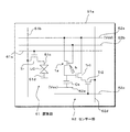
上述した構成の光センサー素子1aを用いた電子機器(表示装置)の他の例としては、光センサー素子1aを備えたセンサー部を表示領域51aの周辺に設け、受光した外光の強度によってバックライト52を調整する機能を備えた構成への適用も可能である。この場合、光センサー素子1aを備えたセンサー部の回路構成は、例えば図7に示すような構成とすることができる。
<Electronic device-2>
As another example of an electronic apparatus (display device) using the
すなわち、MOS型構造の光センサー素子1aは、ソース電極が電源線(Vdd)に接続され、ドレイン電極が容量素子Csとリセット回路と読出回路とに接続されている。そして各光センサー素子1aのゲート電極は、選択制御線65に接続されている。尚、容量素子Csのもう一方の電極は、電源線(Vss)に接続されている。
That is, in the
そして、光センサー素子1aは、上述した光センサー素子1aの構成で述べたように、ここでの図示を省略したリセット回路からの信号によってリセットされ、また光センサー素子1aの半導体層での受光量に対応して不揮発的に変化したドレイン電流が読み出される構成となっている。光センサー素子1aから読み出されたドレイン電流は、容量素子Csに電荷として蓄積され、読出回路からの信号によって外部へ出力される構成となっている。
The
またこのような電子機器(表示装置)においては、図5に示した電子機器(表示装置)5aが備えている受光ドライブ回路54、画像処理部55、およびアプリケーションプログラム実行部56に換えて、光センサー素子1aから出力された電気信号に基づいて、バックライト52の光強度を制御する回路を備えていることとする。
In such an electronic device (display device), a light receiving
このような構成の電子機器(表示装置)であっても、半導体層での受光によって不揮発的にVg−Id特性が変化する光センサー素子1aを用いた高感度な光検出を行うことが可能である。
Even in an electronic apparatus (display device) having such a configuration, it is possible to perform high-sensitivity light detection using the
尚、以上の実施形態においては、光センサー機能(撮像機能)を有する電子機器(表示装置)の一例として液晶表示装置を例示したが、このような電子機器は液晶表示装置に限定されることはなく、本発明構成の光センサー素子1aを用いた電子機器に広く適用可能である。例えば、電子機器が表示装置で有る場合いは、バックライトを用いず有機LED(OLED)を回路面に形成する自発光型の表示装置において、本発明の光センサー素子を設けた構成とすることが可能である。
In the above embodiment, the liquid crystal display device is exemplified as an example of the electronic device (display device) having the optical sensor function (imaging function). However, such an electronic device is limited to the liquid crystal display device. However, the present invention can be widely applied to electronic devices using the
<適用例>
以上説明した本発明に係る光センサー素子またはメモリー素子を備えた電子機器としては、図8〜図12に示す様々な電子機器に適用可能である。例えば、デジタルカメラ、ノート型パーソナルコンピュータ、携帯電話等の携帯端末装置、ビデオカメラなど、電子機器に入力された映像信号、若しくは、電子機器内で生成した映像信号を、画像若しくは映像として表示するあらゆる分野の電子機器であれば、その表示部分に実施形態で説明した光センサー素子を設けて撮像機能を付加させることが可能である。またこれらの電子機器のメモリー機能として、実施形態で説明したメモリー素子を備えたメモリー装置を適用することができる。以下に、本発明が適用される電子機器の一例について説明する。
<Application example>
The electronic device provided with the photosensor element or the memory element according to the present invention described above can be applied to various electronic devices shown in FIGS. For example, any video signal input to an electronic device such as a digital camera, a notebook personal computer, a portable terminal device such as a mobile phone, a video camera, or a video signal generated in the electronic device is displayed as an image or video. In the case of electronic devices in the field, the photo sensor element described in the embodiment can be provided in the display portion to add an imaging function. In addition, as a memory function of these electronic devices, a memory device including the memory element described in the embodiment can be applied. An example of an electronic device to which the present invention is applied will be described below.
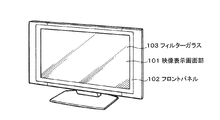
図8は、本発明が適用されるテレビを示す斜視図である。本適用例に係るテレビは、フロントパネル102やフィルターガラス103等から構成される映像表示画面部101を含み、その映像表示画面部101として本発明に係る光センサー素子を設けた表示装置を用いることにより作製される。またこのテレビは、メモリー機能として本発明に係るメモリー素子を備えたメモリー装置を用いることにより作製される。
図9は、本発明が適用されるデジタルカメラを示す図であり、(A)は表側から見た斜視図、(B)は裏側から見た斜視図である。本適用例に係るデジタルカメラは、フラッシュ用の発光部111、表示部112、メニュースイッチ113、シャッターボタン114等を含み、その表示部112として本発明に係る光センサー素子を設けた表示装置を用いることにより作製される。またこのデジタルカメラは、メモリー機能として本発明に係るメモリー素子を備えたメモリー装置を用いることにより作製される。
FIG. 8 is a perspective view showing a television to which the present invention is applied. The television according to this application example includes a video display screen unit 101 including a front panel 102, a filter glass 103, and the like, and a display device provided with the photosensor element according to the present invention is used as the video display screen unit 101. It is produced by. Further, this television is manufactured by using a memory device provided with the memory element according to the present invention as a memory function.
9A and 9B are diagrams showing a digital camera to which the present invention is applied. FIG. 9A is a perspective view seen from the front side, and FIG. 9B is a perspective view seen from the back side. The digital camera according to this application example includes a light emitting unit 111 for flash, a display unit 112, a menu switch 113, a shutter button 114, and the like, and a display device provided with the photosensor element according to the present invention is used as the display unit 112. It is produced by this. The digital camera is manufactured by using a memory device including the memory element according to the present invention as a memory function.
図10は、本発明が適用されるノート型パーソナルコンピュータを示す斜視図である。本適用例に係るノート型パーソナルコンピュータは、本体121に、文字等を入力するとき操作されるキーボード122、画像を表示する表示部123等を含み、その表示部123として本発明に係る光センサー素子を設けた表示装置を用いることにより作製される。またこのノート型パーソナルコンピュータは、メモリー機能として本発明に係るメモリー素子を備えたメモリー装置を用いることにより作製される。 FIG. 10 is a perspective view showing a notebook personal computer to which the present invention is applied. The notebook personal computer according to the application example includes a main body 121 including a keyboard 122 that is operated when characters and the like are input, a display unit 123 that displays an image, and the like. It is manufactured by using a display device provided with. The notebook personal computer is manufactured by using a memory device including the memory element according to the present invention as a memory function.
図11は、本発明が適用されるビデオカメラを示す斜視図である。本適用例に係るビデオカメラは、本体部131、前方を向いた側面に被写体撮影用のレンズ132、撮影時のスタート/ストップスイッチ133、表示部134等を含み、その表示部134として本発明に係る光センサー素子を設けた表示装置を用いることにより作製される。またこのビデオカメラは、メモリー機能として本発明に係るメモリー素子を備えたメモリー装置を用いることにより作製される。 FIG. 11 is a perspective view showing a video camera to which the present invention is applied. The video camera according to this application example includes a main body 131, a lens 132 for shooting an object on a side facing forward, a start / stop switch 133 at the time of shooting, a display unit 134, and the like. It is manufactured by using a display device provided with such an optical sensor element. This video camera is manufactured by using a memory device including the memory element according to the present invention as a memory function.
図12は、本発明が適用される携帯端末装置、例えば携帯電話機を示す図であり、(A)は開いた状態での正面図、(B)はその側面図、(C)は閉じた状態での正面図、(D)は左側面図、(E)は右側面図、(F)は上面図、(G)は下面図である。本適用例に係る携帯電話機は、上側筐体141、下側筐体142、連結部(ここではヒンジ部)143、ディスプレイ144、サブディスプレイ145、ピクチャーライト146、カメラ147等を含み、そのディスプレイ144やサブディスプレイ145として本発明に係る光センサー素子を設けた表示装置を用いることにより作製される。またこの携帯電話機は、メモリー機能として本発明に係るメモリー素子を備えたメモリー装置を用いることにより作製される。 12A and 12B are diagrams showing a mobile terminal device to which the present invention is applied, for example, a mobile phone. FIG. 12A is a front view in an opened state, FIG. 12B is a side view thereof, and FIG. (D) is a left side view, (E) is a right side view, (F) is a top view, and (G) is a bottom view. The mobile phone according to this application example includes an upper housing 141, a lower housing 142, a connecting portion (here, a hinge portion) 143, a display 144, a sub display 145, a picture light 146, a camera 147, and the like. Alternatively, the sub-display 145 is manufactured by using a display device provided with the photosensor element according to the present invention. The cellular phone is manufactured by using a memory device including the memory element according to the present invention as a memory function.
1a…光センサー素子、1b…メモリー素子、3a…撮像装置、3b…メモリー装置(電子機器)、5a…電子機器、13…ゲート電極、15…ゲート絶縁膜、17…半導体層、19s…ソース電極、19d…ドレイン電極、A…初期状態、Vth…しきい値電圧
DESCRIPTION OF
Claims (17)
前記半導体層での受光量を、該半導体層での受光期間後にゲート電圧に対して不揮発的に変化したドレイン電流値として読み出す駆動部とを備える撮像装置。 Ri consists oxide semiconductor, the drain current versus gate voltage is a gate electrode provided via a gate insulating film relative to the semiconductor layer that varies in a nonvolatile manner, a source electrode and a drain electrode connected to said semiconductor layer An imaging region in which photosensor elements are arranged ; and
An imaging apparatus comprising: a drive unit that reads the amount of light received by the semiconductor layer as a drain current value that changes in a non-volatile manner with respect to a gate voltage after a light reception period of the semiconductor layer .
前記半導体層での受光量を、該半導体層での受光期間後にゲート電圧に対して不揮発的に変化したドレイン電流値として読み出す駆動部とを備える電子機器。 Ri consists oxide semiconductor, the drain current versus gate voltage is a gate electrode provided via a gate insulating film relative to the semiconductor layer that varies in a nonvolatile manner, a source electrode and a drain electrode connected to said semiconductor layer A display area in which photosensor elements are arranged ;
An electronic apparatus comprising: a drive unit that reads the amount of light received by the semiconductor layer as a drain current value that changes in a non-volatile manner with respect to a gate voltage after the light reception period of the semiconductor layer .
前記半導体層での受光量を、該半導体層での受光期間後にゲート電圧に対して不揮発的に変化したドレイン電流値として読み出す駆動部とを備えるメモリー装置。 Ri consists oxide semiconductor, the drain current versus gate voltage is a gate electrode provided via a gate insulating film relative to the semiconductor layer that varies in a nonvolatile manner, a source electrode and a drain electrode connected to said semiconductor layer An area where memory elements are arranged ; and
A memory device comprising: a drive unit that reads an amount of light received by the semiconductor layer as a drain current value that changes in a non-volatile manner with respect to a gate voltage after a light reception period of the semiconductor layer .
前記半導体層での受光量を、該半導体層での受光期間後にゲート電圧に対して不揮発的に変化したドレイン電流値として読み出す駆動部とを備えるメモリー装置を有する電子機器。 Ri consists oxide semiconductor, the drain current versus gate voltage is a gate electrode provided via a gate insulating film relative to the semiconductor layer that varies in a nonvolatile manner, a source electrode and a drain electrode connected to said semiconductor layer An area where memory elements are arranged ; and
An electronic device having a memory device comprising a light reception amount of the previous SL semiconductor layer, and a driving unit for reading the drain current value changed in a non-volatile manner with respect to the gate voltage after the light receiving period at the semiconductor layer.
Priority Applications (5)
| Application Number | Priority Date | Filing Date | Title |
|---|---|---|---|
| JP2008020558A JP5121478B2 (en) | 2008-01-31 | 2008-01-31 | Optical sensor element, imaging device, electronic device, and memory element |
| TW097151683A TWI384634B (en) | 2008-01-31 | 2008-12-31 | Optical sensor element, imaging device, electronic equipment and memory element |
| CN2009100098102A CN101499498B (en) | 2008-01-31 | 2009-01-23 | Optical sensor element, image forming apparatus, electronic apparatus and storage element |
| US12/361,049 US8194469B2 (en) | 2008-01-31 | 2009-01-28 | Optical sensor element, imaging device, electronic equipment and memory element |
| KR1020090006948A KR101562609B1 (en) | 2008-01-31 | 2009-01-29 | Optical sensor element imaging device electronic equipment and memory element |
Applications Claiming Priority (1)
| Application Number | Priority Date | Filing Date | Title |
|---|---|---|---|
| JP2008020558A JP5121478B2 (en) | 2008-01-31 | 2008-01-31 | Optical sensor element, imaging device, electronic device, and memory element |
Publications (3)
| Publication Number | Publication Date |
|---|---|
| JP2009182194A JP2009182194A (en) | 2009-08-13 |
| JP2009182194A5 JP2009182194A5 (en) | 2011-02-03 |
| JP5121478B2 true JP5121478B2 (en) | 2013-01-16 |
Family
ID=40946465
Family Applications (1)
| Application Number | Title | Priority Date | Filing Date |
|---|---|---|---|
| JP2008020558A Expired - Fee Related JP5121478B2 (en) | 2008-01-31 | 2008-01-31 | Optical sensor element, imaging device, electronic device, and memory element |
Country Status (5)
| Country | Link |
|---|---|
| US (1) | US8194469B2 (en) |
| JP (1) | JP5121478B2 (en) |
| KR (1) | KR101562609B1 (en) |
| CN (1) | CN101499498B (en) |
| TW (1) | TWI384634B (en) |
Families Citing this family (122)
| Publication number | Priority date | Publication date | Assignee | Title |
|---|---|---|---|---|
| JP2009146100A (en) * | 2007-12-13 | 2009-07-02 | Sony Corp | Display device and light sensor element |
| JP4756490B2 (en) | 2009-02-23 | 2011-08-24 | 奇美電子股▲ふん▼有限公司 | Display device and electronic apparatus including the same |
| KR101721285B1 (en) | 2009-10-09 | 2017-03-29 | 가부시키가이샤 한도오따이 에네루기 켄큐쇼 | Shift register and display device |
| KR20230130771A (en) | 2009-10-29 | 2023-09-12 | 가부시키가이샤 한도오따이 에네루기 켄큐쇼 | Semiconductor device |
| EP2494599B1 (en) | 2009-10-30 | 2020-10-07 | Semiconductor Energy Laboratory Co., Ltd. | Semiconductor device |
| IN2012DN03080A (en) * | 2009-10-30 | 2015-07-31 | Semiconductor Energy Lab | |
| WO2011055660A1 (en) | 2009-11-06 | 2011-05-12 | Semiconductor Energy Laboratory Co., Ltd. | Semiconductor device |
| WO2011055669A1 (en) | 2009-11-06 | 2011-05-12 | Semiconductor Energy Laboratory Co., Ltd. | Semiconductor device |
| KR101696410B1 (en) | 2009-11-11 | 2017-01-16 | 삼성전자주식회사 | Image sensor and method of operating the same |
| KR101893332B1 (en) | 2009-11-13 | 2018-08-31 | 가부시키가이샤 한도오따이 에네루기 켄큐쇼 | Semiconductor device and driving method thereof |
| WO2011062029A1 (en) | 2009-11-18 | 2011-05-26 | Semiconductor Energy Laboratory Co., Ltd. | Memory device |
| WO2011062067A1 (en) * | 2009-11-20 | 2011-05-26 | Semiconductor Energy Laboratory Co., Ltd. | Semiconductor device |
| KR102451852B1 (en) | 2009-11-20 | 2022-10-11 | 가부시키가이샤 한도오따이 에네루기 켄큐쇼 | Semiconductor device |
| KR101662359B1 (en) * | 2009-11-24 | 2016-10-04 | 가부시키가이샤 한도오따이 에네루기 켄큐쇼 | Semiconductor device including memory cell |
| KR101911382B1 (en) * | 2009-11-27 | 2018-10-24 | 가부시키가이샤 한도오따이 에네루기 켄큐쇼 | Semiconductor device |
| JP5584103B2 (en) | 2009-12-04 | 2014-09-03 | 株式会社半導体エネルギー研究所 | Semiconductor device |
| JP2011139052A (en) | 2009-12-04 | 2011-07-14 | Semiconductor Energy Lab Co Ltd | Semiconductor memory device |
| CN102652356B (en) | 2009-12-18 | 2016-02-17 | 株式会社半导体能源研究所 | Semiconductor device |
| WO2011077978A1 (en) | 2009-12-25 | 2011-06-30 | Semiconductor Energy Laboratory Co., Ltd. | Method for manufacturing display device |
| KR101473684B1 (en) | 2009-12-25 | 2014-12-18 | 가부시키가이샤 한도오따이 에네루기 켄큐쇼 | Semiconductor device |
| KR101994632B1 (en) | 2009-12-25 | 2019-07-02 | 가부시키가이샤 한도오따이 에네루기 켄큐쇼 | Semiconductor device |
| KR101842413B1 (en) | 2009-12-28 | 2018-03-26 | 가부시키가이샤 한도오따이 에네루기 켄큐쇼 | Semiconductor device |
| CN102656691B (en) | 2009-12-28 | 2015-07-29 | 株式会社半导体能源研究所 | Storage arrangement and semiconductor device |
| WO2011080999A1 (en) | 2009-12-28 | 2011-07-07 | Semiconductor Energy Laboratory Co., Ltd. | Semiconductor device |
| KR101631652B1 (en) * | 2009-12-29 | 2016-06-20 | 삼성전자주식회사 | Image sensor using light-sensitive transparent oxide semiconductor material |
| KR101791279B1 (en) * | 2010-01-15 | 2017-10-27 | 가부시키가이샤 한도오따이 에네루기 켄큐쇼 | Semiconductor device |
| KR101798367B1 (en) | 2010-01-15 | 2017-11-16 | 가부시키가이샤 한도오따이 에네루기 켄큐쇼 | Semiconductor device |
| US8780629B2 (en) | 2010-01-15 | 2014-07-15 | Semiconductor Energy Laboratory Co., Ltd. | Semiconductor device and driving method thereof |
| US8415731B2 (en) | 2010-01-20 | 2013-04-09 | Semiconductor Energy Laboratory Co., Ltd. | Semiconductor storage device with integrated capacitor and having transistor overlapping sections |
| KR101855060B1 (en) | 2010-01-22 | 2018-05-09 | 가부시키가이샤 한도오따이 에네루기 켄큐쇼 | Semiconductor memory device and driving method thereof |
| WO2011093003A1 (en) | 2010-01-29 | 2011-08-04 | Semiconductor Energy Laboratory Co., Ltd. | Semiconductor memory device |
| WO2011096277A1 (en) | 2010-02-05 | 2011-08-11 | Semiconductor Energy Laboratory Co., Ltd. | Semiconductor device and method of driving semiconductor device |
| WO2011096264A1 (en) * | 2010-02-05 | 2011-08-11 | Semiconductor Energy Laboratory Co., Ltd. | Semiconductor device and method of driving semiconductor device |
| KR101926336B1 (en) | 2010-02-05 | 2019-03-07 | 가부시키가이샤 한도오따이 에네루기 켄큐쇼 | Semiconductor device |
| WO2011096270A1 (en) | 2010-02-05 | 2011-08-11 | Semiconductor Energy Laboratory Co., Ltd. | Semiconductor device |
| WO2011099336A1 (en) * | 2010-02-12 | 2011-08-18 | Semiconductor Energy Laboratory Co., Ltd. | Semiconductor device and driving method thereof |
| KR101811204B1 (en) | 2010-02-12 | 2017-12-22 | 가부시키가이샤 한도오따이 에네루기 켄큐쇼 | Semiconductor device and driving method of the same |
| KR101775180B1 (en) * | 2010-02-12 | 2017-09-05 | 가부시키가이샤 한도오따이 에네루기 켄큐쇼 | Semiconductor device and method for driving the same |
| KR102015762B1 (en) | 2010-02-19 | 2019-08-29 | 가부시키가이샤 한도오따이 에네루기 켄큐쇼 | Semiconductor memory device, driving method thereof, and method for manufacturing semiconductor device |
| WO2011108475A1 (en) | 2010-03-04 | 2011-09-09 | Semiconductor Energy Laboratory Co., Ltd. | Semiconductor memory device and semiconductor device |
| WO2011111490A1 (en) * | 2010-03-08 | 2011-09-15 | Semiconductor Energy Laboratory Co., Ltd. | Semiconductor device and driving method thereof |
| WO2011114866A1 (en) | 2010-03-17 | 2011-09-22 | Semiconductor Energy Laboratory Co., Ltd. | Memory device and semiconductor device |
| KR101840797B1 (en) | 2010-03-19 | 2018-03-21 | 가부시키가이샤 한도오따이 에네루기 켄큐쇼 | Semiconductor memory device |
| WO2011114867A1 (en) * | 2010-03-19 | 2011-09-22 | Semiconductor Energy Laboratory Co., Ltd. | Semiconductor device and driving method of semiconductor device |
| US9891102B2 (en) | 2010-04-22 | 2018-02-13 | Samsung Electronics Co., Ltd. | Simplified light sensing circuit, light sensing apparatus including the light sensing circuit, method of driving the light sensing apparatus, and image acquisition apparatus and optical touch screen apparatus including the light sensing apparatus |
| KR101652786B1 (en) | 2010-04-22 | 2016-09-12 | 삼성전자주식회사 | Simplified light sensing circuit, and remote optical touch panel and image acquisition apparatus employing the circuit |
| KR102056905B1 (en) * | 2011-07-25 | 2019-12-18 | 삼성전자주식회사 | Light sensing apparatus and method of driving the light sensing apparatus, and optical touch screen apparatus including the light sensing apparatus |
| TWI511236B (en) | 2010-05-14 | 2015-12-01 | Semiconductor Energy Lab | Semiconductor device |
| KR101672344B1 (en) * | 2010-05-20 | 2016-11-04 | 삼성전자주식회사 | Light sensing circuit, method of operating the light sensing circuit, and light sensing apparatus employing the light sensing circuit |
| US8416622B2 (en) | 2010-05-20 | 2013-04-09 | Semiconductor Energy Laboratory Co., Ltd. | Driving method of a semiconductor device with an inverted period having a negative potential applied to a gate of an oxide semiconductor transistor |
| WO2011145468A1 (en) | 2010-05-21 | 2011-11-24 | Semiconductor Energy Laboratory Co., Ltd. | Memory device and semiconductor device |
| US8637802B2 (en) | 2010-06-18 | 2014-01-28 | Semiconductor Energy Laboratory Co., Ltd. | Photosensor, semiconductor device including photosensor, and light measurement method using photosensor |
| WO2012002186A1 (en) | 2010-07-02 | 2012-01-05 | Semiconductor Energy Laboratory Co., Ltd. | Semiconductor device |
| WO2012008304A1 (en) | 2010-07-16 | 2012-01-19 | Semiconductor Energy Laboratory Co., Ltd. | Semiconductor device |
| JP5846789B2 (en) | 2010-07-29 | 2016-01-20 | 株式会社半導体エネルギー研究所 | Semiconductor device |
| TWI555128B (en) | 2010-08-06 | 2016-10-21 | 半導體能源研究所股份有限公司 | Semiconductor device and driving method thereof |
| US8792284B2 (en) | 2010-08-06 | 2014-07-29 | Semiconductor Energy Laboratory Co., Ltd. | Oxide semiconductor memory device |
| TWI524347B (en) | 2010-08-06 | 2016-03-01 | 半導體能源研究所股份有限公司 | Semiconductor device and method for driving semiconductor device |
| US8422272B2 (en) | 2010-08-06 | 2013-04-16 | Semiconductor Energy Laboratory Co., Ltd. | Semiconductor device and driving method thereof |
| TWI605549B (en) | 2010-08-06 | 2017-11-11 | 半導體能源研究所股份有限公司 | Semiconductor device |
| US9343480B2 (en) * | 2010-08-16 | 2016-05-17 | Semiconductor Energy Laboratory Co., Ltd. | Semiconductor device |
| KR20120017258A (en) * | 2010-08-18 | 2012-02-28 | 삼성모바일디스플레이주식회사 | Thin film charged body sensor |
| US8593858B2 (en) | 2010-08-31 | 2013-11-26 | Semiconductor Energy Laboratory Co., Ltd. | Driving method of semiconductor device |
| US8634228B2 (en) | 2010-09-02 | 2014-01-21 | Semiconductor Energy Laboratory Co., Ltd. | Driving method of semiconductor device |
| WO2012029637A1 (en) | 2010-09-03 | 2012-03-08 | Semiconductor Energy Laboratory Co., Ltd. | Semiconductor device and driving method thereof |
| KR101754949B1 (en) * | 2010-09-06 | 2017-07-07 | 삼성디스플레이 주식회사 | organic luminescence display |
| US8520426B2 (en) | 2010-09-08 | 2013-08-27 | Semiconductor Energy Laboratory Co., Ltd. | Method for driving semiconductor device |
| JP2012256821A (en) | 2010-09-13 | 2012-12-27 | Semiconductor Energy Lab Co Ltd | Memory device |
| TWI543166B (en) | 2010-09-13 | 2016-07-21 | 半導體能源研究所股份有限公司 | Semiconductor device |
| KR101778224B1 (en) | 2010-10-12 | 2017-09-15 | 삼성전자주식회사 | Transistor, method of manufacturing the same and electronic device comprising transistor |
| KR101952456B1 (en) | 2010-10-29 | 2019-02-26 | 가부시키가이샤 한도오따이 에네루기 켄큐쇼 | Storage device |
| KR101952733B1 (en) | 2010-11-05 | 2019-02-27 | 가부시키가이샤 한도오따이 에네루기 켄큐쇼 | Semiconductor device |
| US8936965B2 (en) * | 2010-11-26 | 2015-01-20 | Semiconductor Energy Laboratory Co., Ltd. | Semiconductor device and manufacturing method thereof |
| JP5912467B2 (en) * | 2010-12-10 | 2016-04-27 | 株式会社半導体エネルギー研究所 | Photoelectric conversion circuit and display device |
| JP2012142562A (en) | 2010-12-17 | 2012-07-26 | Semiconductor Energy Lab Co Ltd | Semiconductor memory device |
| JP5993141B2 (en) | 2010-12-28 | 2016-09-14 | 株式会社半導体エネルギー研究所 | Storage device |
| JP2012151453A (en) | 2010-12-28 | 2012-08-09 | Semiconductor Energy Lab Co Ltd | Semiconductor device and driving method of the same |
| US8421071B2 (en) | 2011-01-13 | 2013-04-16 | Semiconductor Energy Laboratory Co., Ltd. | Memory device |
| KR102026718B1 (en) | 2011-01-14 | 2019-09-30 | 가부시키가이샤 한도오따이 에네루기 켄큐쇼 | Memory device, semiconductor device, and detecting method |
| JP5933897B2 (en) * | 2011-03-18 | 2016-06-15 | 株式会社半導体エネルギー研究所 | Semiconductor device |
| CN102738182A (en) * | 2011-03-31 | 2012-10-17 | 宏碁股份有限公司 | Optical sensor device of amorphous oxide semiconductor, and fabrication method thereof |
| JP5946683B2 (en) | 2011-04-22 | 2016-07-06 | 株式会社半導体エネルギー研究所 | Semiconductor device |
| KR101906974B1 (en) * | 2011-04-25 | 2018-10-12 | 삼성전자주식회사 | Light sensing apparatus and method of driving the light sensing apparatus |
| US8729545B2 (en) | 2011-04-28 | 2014-05-20 | Semiconductor Energy Laboratory Co., Ltd. | Semiconductor memory device |
| KR102021908B1 (en) * | 2011-05-03 | 2019-09-18 | 삼성전자주식회사 | Optical touch screen apparatus and method of driving the optical touch screen apparatus |
| JP6013682B2 (en) | 2011-05-20 | 2016-10-25 | 株式会社半導体エネルギー研究所 | Driving method of semiconductor device |
| JP5052693B1 (en) * | 2011-08-12 | 2012-10-17 | 富士フイルム株式会社 | Thin film transistor and manufacturing method thereof, display device, image sensor, X-ray sensor, and X-ray digital imaging device |
| CN102651422A (en) * | 2011-10-10 | 2012-08-29 | 京东方科技集团股份有限公司 | Short wavelength photodetector and manufacturing method thereof |
| JP6081171B2 (en) | 2011-12-09 | 2017-02-15 | 株式会社半導体エネルギー研究所 | Storage device |
| US9208849B2 (en) | 2012-04-12 | 2015-12-08 | Semiconductor Energy Laboratory Co., Ltd. | Semiconductor device and method for driving semiconductor device, and electronic device |
| EP2836997A1 (en) * | 2012-04-13 | 2015-02-18 | Koninklijke Philips N.V. | Data generating system and lighting device |
| JP6005391B2 (en) * | 2012-05-01 | 2016-10-12 | 株式会社半導体エネルギー研究所 | Semiconductor device |
| JP5901420B2 (en) * | 2012-05-14 | 2016-04-13 | 富士フイルム株式会社 | Thin film transistor manufacturing method |
| CN102751240B (en) * | 2012-05-18 | 2015-03-11 | 京东方科技集团股份有限公司 | Thin film transistor array substrate, manufacturing method thereof, display panel and display device |
| KR101906971B1 (en) * | 2012-09-27 | 2018-10-11 | 삼성전자주식회사 | Hybrid touch panel, hybrid touch screen apparatus and method of driving the same |
| JP2014142986A (en) | 2012-12-26 | 2014-08-07 | Semiconductor Energy Lab Co Ltd | Semiconductor device |
| JP2014195060A (en) * | 2013-03-01 | 2014-10-09 | Semiconductor Energy Lab Co Ltd | Sensor circuit and semiconductor device using sensor circuit |
| JP6132283B2 (en) * | 2013-05-17 | 2017-05-24 | Nltテクノロジー株式会社 | Amplifier circuit and image sensor using the amplifier circuit |
| JP6516978B2 (en) | 2013-07-17 | 2019-05-22 | 株式会社半導体エネルギー研究所 | Semiconductor device |
| US9590110B2 (en) * | 2013-09-10 | 2017-03-07 | Semiconductor Energy Laboratory Co., Ltd. | Ultraviolet light sensor circuit |
| JP2015084418A (en) | 2013-09-23 | 2015-04-30 | 株式会社半導体エネルギー研究所 | Semiconductor device |
| JP6570817B2 (en) | 2013-09-23 | 2019-09-04 | 株式会社半導体エネルギー研究所 | Semiconductor device |
| JP2015149414A (en) * | 2014-02-06 | 2015-08-20 | 株式会社東芝 | Semiconductor device and imaging apparatus |
| JP6560508B2 (en) | 2014-03-13 | 2019-08-14 | 株式会社半導体エネルギー研究所 | Semiconductor device |
| TWI555217B (en) * | 2014-05-29 | 2016-10-21 | 友達光電股份有限公司 | Optic detector |
| KR20150138026A (en) | 2014-05-29 | 2015-12-09 | 가부시키가이샤 한도오따이 에네루기 켄큐쇼 | Semiconductor device |
| WO2017018933A1 (en) * | 2015-07-24 | 2017-02-02 | Nanyang Technological University | Sensor element, image sensor, methods of forming and operating the same |
| US9773787B2 (en) | 2015-11-03 | 2017-09-26 | Semiconductor Energy Laboratory Co., Ltd. | Semiconductor device, memory device, electronic device, or method for driving the semiconductor device |
| US10573621B2 (en) * | 2016-02-25 | 2020-02-25 | Semiconductor Energy Laboratory Co., Ltd. | Imaging system and manufacturing apparatus |
| JP6801891B2 (en) * | 2016-03-02 | 2020-12-16 | 国立研究開発法人産業技術総合研究所 | Semiconductor-insulator reversible change thin film and its manufacturing method |
| SG10201701689UA (en) | 2016-03-18 | 2017-10-30 | Semiconductor Energy Lab | Semiconductor device, semiconductor wafer, and electronic device |
| US10490116B2 (en) | 2016-07-06 | 2019-11-26 | Semiconductor Energy Laboratory Co., Ltd. | Semiconductor device, memory device, and display system |
| KR102458660B1 (en) | 2016-08-03 | 2022-10-26 | 가부시키가이샤 한도오따이 에네루기 켄큐쇼 | Display device and electronic device |
| US10483300B2 (en) | 2017-06-02 | 2019-11-19 | Electronics And Telecommunications Research Institute | Optically restorable semiconductor device, method for fabricating the same, and flash memory device using the same |
| US10746614B2 (en) * | 2017-09-18 | 2020-08-18 | Korea University Research And Business Foundation, Sejong Campus | Stretchable multimodal sensor and method of fabricating of the same |
| KR101912714B1 (en) * | 2017-09-29 | 2018-10-29 | 삼성전자주식회사 | Optical touch screen apparatus and method of driving the optical touch screen apparatus |
| CN107910331B (en) * | 2017-11-17 | 2020-07-28 | 南方科技大学 | Nonvolatile memory unit and preparation method thereof |
| KR101951322B1 (en) * | 2017-12-14 | 2019-02-22 | 삼성전자주식회사 | Light sensing apparatus and method of driving the light sensing apparatus, and optical touch screen apparatus including the light sensing apparatus |
| KR102478540B1 (en) * | 2017-12-22 | 2022-12-15 | 엘지디스플레이 주식회사 | Organic emitting diode display device |
| JP7326518B2 (en) | 2018-03-20 | 2023-08-15 | 株式会社ジャパンディスプレイ | Optical sensor device |
| JP7039346B2 (en) | 2018-03-20 | 2022-03-22 | 株式会社ジャパンディスプレイ | Optical sensor circuit, optical sensor device, and display device |
| TWI718378B (en) * | 2018-05-23 | 2021-02-11 | 友達光電股份有限公司 | Optical detection device and detection method thereof |
Family Cites Families (12)
| Publication number | Priority date | Publication date | Assignee | Title |
|---|---|---|---|---|
| JP3246034B2 (en) * | 1993-02-05 | 2002-01-15 | カシオ計算機株式会社 | Photosensor and photosensor driving method |
| JP2003101029A (en) * | 2001-09-20 | 2003-04-04 | Casio Comput Co Ltd | Thin film transistor, photosensor, and method of manufacturing the same |
| US7189992B2 (en) * | 2002-05-21 | 2007-03-13 | State Of Oregon Acting By And Through The Oregon State Board Of Higher Education On Behalf Of Oregon State University | Transistor structures having a transparent channel |
| US7339187B2 (en) * | 2002-05-21 | 2008-03-04 | State Of Oregon Acting By And Through The Oregon State Board Of Higher Education On Behalf Of Oregon State University | Transistor structures |
| JP2006121029A (en) * | 2004-09-27 | 2006-05-11 | Tokyo Institute Of Technology | Solid electronic apparatus |
| JP2006165530A (en) | 2004-11-10 | 2006-06-22 | Canon Inc | Sensor and non-planar imager |
| US7453065B2 (en) * | 2004-11-10 | 2008-11-18 | Canon Kabushiki Kaisha | Sensor and image pickup device |
| CN100414357C (en) * | 2004-11-26 | 2008-08-27 | 三洋电机株式会社 | Optical sensor and display |
| JP2006186853A (en) * | 2004-12-28 | 2006-07-13 | Casio Comput Co Ltd | Read driving circuit, driving control method thereof and image reading apparatus |
| JP5116225B2 (en) * | 2005-09-06 | 2013-01-09 | キヤノン株式会社 | Manufacturing method of oxide semiconductor device |
| US7710787B2 (en) | 2006-04-11 | 2010-05-04 | Analog Devices, Inc. | Method of erasing an EEPROM device |
| KR100825383B1 (en) * | 2006-04-24 | 2008-04-29 | 삼성에스디아이 주식회사 | Nonvolatile memory device, fabricating the same and organic electroluminescence display device including the same |
-
2008
- 2008-01-31 JP JP2008020558A patent/JP5121478B2/en not_active Expired - Fee Related
- 2008-12-31 TW TW097151683A patent/TWI384634B/en not_active IP Right Cessation
-
2009
- 2009-01-23 CN CN2009100098102A patent/CN101499498B/en not_active Expired - Fee Related
- 2009-01-28 US US12/361,049 patent/US8194469B2/en not_active Expired - Fee Related
- 2009-01-29 KR KR1020090006948A patent/KR101562609B1/en not_active IP Right Cessation
Also Published As
| Publication number | Publication date |
|---|---|
| CN101499498B (en) | 2012-07-11 |
| KR101562609B1 (en) | 2015-10-23 |
| TWI384634B (en) | 2013-02-01 |
| KR20090084708A (en) | 2009-08-05 |
| US20100097838A1 (en) | 2010-04-22 |
| CN101499498A (en) | 2009-08-05 |
| JP2009182194A (en) | 2009-08-13 |
| US8194469B2 (en) | 2012-06-05 |
| TW200935615A (en) | 2009-08-16 |
Similar Documents
| Publication | Publication Date | Title |
|---|---|---|
| JP5121478B2 (en) | Optical sensor element, imaging device, electronic device, and memory element | |
| JP5721994B2 (en) | Radiation imaging device | |
| JP5068149B2 (en) | Optical sensor element, optical sensor element driving method, display apparatus, and display apparatus driving method | |
| JP2009146100A (en) | Display device and light sensor element | |
| US8144102B2 (en) | Memory element and display device | |
| TWI513302B (en) | Semiconductor device | |
| JP5481462B2 (en) | Pixel array and display panel having the same | |
| US8537082B2 (en) | Display and electronic apparatus | |
| KR101889382B1 (en) | Electronic device and electronic system | |
| US8269748B2 (en) | Display and electronic apparatus | |
| TW201205379A (en) | Electronic device and electronic system | |
| JP5814664B2 (en) | LCD display system | |
| JP2009135188A (en) | Photosensor and display device | |
| KR102192956B1 (en) | User terminal apparatus and control method thereof | |
| JP7039346B2 (en) | Optical sensor circuit, optical sensor device, and display device | |
| JP2009229908A (en) | Display device | |
| JP2009135260A (en) | Optical sensor and display device | |
| JP2009063803A (en) | Display device | |
| JP4702395B2 (en) | Display device and electronic device | |
| JP5183173B2 (en) | Optical sensor and display device | |
| US20230157126A1 (en) | Image display device and electronic apparatus | |
| JP2009272577A (en) | Thin film transistor, method of manufacturing thin film transistor, and display device | |
| KR100936186B1 (en) | Liquid crystal display panel | |
| CN114556580A (en) | Display substrate and display device |
Legal Events
| Date | Code | Title | Description |
|---|---|---|---|
| A521 | Request for written amendment filed |
Free format text: JAPANESE INTERMEDIATE CODE: A821 Effective date: 20091014 |
|
| RD02 | Notification of acceptance of power of attorney |
Free format text: JAPANESE INTERMEDIATE CODE: A7422 Effective date: 20091014 |
|
| RD04 | Notification of resignation of power of attorney |
Free format text: JAPANESE INTERMEDIATE CODE: A7424 Effective date: 20091030 |
|
| A521 | Request for written amendment filed |
Free format text: JAPANESE INTERMEDIATE CODE: A523 Effective date: 20101210 |
|
| A621 | Written request for application examination |
Free format text: JAPANESE INTERMEDIATE CODE: A621 Effective date: 20101210 |
|
| A977 | Report on retrieval |
Free format text: JAPANESE INTERMEDIATE CODE: A971007 Effective date: 20111004 |
|
| A131 | Notification of reasons for refusal |
Free format text: JAPANESE INTERMEDIATE CODE: A131 Effective date: 20111011 |
|
| A521 | Request for written amendment filed |
Free format text: JAPANESE INTERMEDIATE CODE: A523 Effective date: 20111202 |
|
| A711 | Notification of change in applicant |
Free format text: JAPANESE INTERMEDIATE CODE: A711 Effective date: 20120330 |
|
| TRDD | Decision of grant or rejection written | ||
| A01 | Written decision to grant a patent or to grant a registration (utility model) |
Free format text: JAPANESE INTERMEDIATE CODE: A01 Effective date: 20121002 |
|
| A01 | Written decision to grant a patent or to grant a registration (utility model) |
Free format text: JAPANESE INTERMEDIATE CODE: A01 |
|
| A61 | First payment of annual fees (during grant procedure) |
Free format text: JAPANESE INTERMEDIATE CODE: A61 Effective date: 20121023 |
|
| FPAY | Renewal fee payment (event date is renewal date of database) |
Free format text: PAYMENT UNTIL: 20151102 Year of fee payment: 3 |
|
| R150 | Certificate of patent or registration of utility model |
Free format text: JAPANESE INTERMEDIATE CODE: R150 Ref document number: 5121478 Country of ref document: JP Free format text: JAPANESE INTERMEDIATE CODE: R150 |
|
| R250 | Receipt of annual fees |
Free format text: JAPANESE INTERMEDIATE CODE: R250 |
|
| R250 | Receipt of annual fees |
Free format text: JAPANESE INTERMEDIATE CODE: R250 |
|
| R250 | Receipt of annual fees |
Free format text: JAPANESE INTERMEDIATE CODE: R250 |
|
| R250 | Receipt of annual fees |
Free format text: JAPANESE INTERMEDIATE CODE: R250 |
|
| R250 | Receipt of annual fees |
Free format text: JAPANESE INTERMEDIATE CODE: R250 |
|
| LAPS | Cancellation because of no payment of annual fees |