JP5112031B2 - Air conditioner - Google Patents
Air conditioner Download PDFInfo
- Publication number
- JP5112031B2 JP5112031B2 JP2007315456A JP2007315456A JP5112031B2 JP 5112031 B2 JP5112031 B2 JP 5112031B2 JP 2007315456 A JP2007315456 A JP 2007315456A JP 2007315456 A JP2007315456 A JP 2007315456A JP 5112031 B2 JP5112031 B2 JP 5112031B2
- Authority
- JP
- Japan
- Prior art keywords
- air
- room
- distance
- distance data
- person
- Prior art date
- Legal status (The legal status is an assumption and is not a legal conclusion. Google has not performed a legal analysis and makes no representation as to the accuracy of the status listed.)
- Expired - Fee Related
Links
Images


Description
本発明は、主として、室内機、室外機から構成されるセパレート型の空気調和機に関するものである。 The present invention relates to a separate type air conditioner mainly composed of an indoor unit and an outdoor unit.
空気調和機は、その室内機の設置位置あるいは設置空間(部屋等)に関しての情報は基本的には持たない。従って、室内機の設置位置や設置空間に適した空調を行うためには設定温度や風量の調整だけでは不十分であり、ユーザー自身がリモコン等により吹出口に設けられたルーバーの角度を調整し、風向きを最適角度に変更することが必要であった。 The air conditioner basically has no information regarding the installation position or installation space (room, etc.) of the indoor unit. Therefore, it is not enough to adjust the set temperature and air volume in order to perform air conditioning suitable for the installation position and installation space of the indoor unit, and the user himself adjusts the angle of the louver provided at the outlet using a remote control or the like. It was necessary to change the wind direction to the optimum angle.
または、高級タイプ(ハイエンド機種)の空気調和機になると設置時に室内機の設置位置情報を入力することが可能であるが、あくまでも目安であり、本来の最適の角度にルーバーを移動したり、最適の回転数に調整しているものではない。 Or, if it becomes a high-end type (high-end model) air conditioner, it is possible to input the installation position information of the indoor unit at the time of installation, but it is only a guideline, and the louver can be moved to the original optimum angle, It is not adjusted to the number of revolutions.
また、部屋の中にいる人の認識にしても、焦電センサー(赤外線センサー)を用いて、熱源を探り出し人がいることを認識することはできたが、あくまで空気調和機に対してどの方向にいるか程度の情報しか得られず、距離や人数までは正確に測定できない。また、カメラ画像を画像処理を用いて行うこともできるが、2次元情報なので正確な距離はつかめない。また、カメラを2台設置することにより、距離データを検出することは可能であるが、処理が煩雑であり、現状では家庭用の空気調和機に搭載できるほどのコストでシステムを構成することはできない。 In addition, even in the recognition of people in the room, it was possible to detect the heat source by using a pyroelectric sensor (infrared sensor), but it was possible to recognize the direction of the air conditioner. It is only possible to obtain information on the degree to which it is present, and it is impossible to accurately measure distance and number of people. Moreover, although a camera image can also be performed using image processing, since it is two-dimensional information, an accurate distance cannot be grasped. In addition, it is possible to detect distance data by installing two cameras, but the processing is complicated, and at present it is not possible to configure a system at a cost that can be installed in a home air conditioner. Can not.
また、特許文献1によれば、画面を区分けして、そこに人が入るかどうかを見極めることにより、人物までの方向及び距離などを推定しているが、そもそも市販の空気調和機にこのようなシステムを採用する場合では、室内機の設置位置により、イニシャライズする必要があり(取り付け場所の高さや、前後左右の壁までの距離により画面の区分けを調整する必要がある)、実用的ではない。また、同文献の実施形態には、2つのカメラを搭載したものを提案しているが、イニシャライズの方法については触れていない。 According to Patent Document 1, the direction and distance to a person are estimated by dividing the screen and determining whether or not a person enters the screen. When using a simple system, it is necessary to initialize depending on the installation position of the indoor unit (it is necessary to adjust the screen division according to the height of the installation location and the distance to the front, rear, left and right walls), which is not practical . Further, the embodiment of the same document proposes a camera equipped with two cameras, but does not mention the initialization method.
また、空気調和機は基本的に、室温と設定温度の差を見ながらフィードバック制御により出力を調整している。しかしながら、人が入ってきた時などは、例えば冷房時では、人が入ってきて室温が上がったことを感知してから、出力を制御することとなり、後追い的な制御となる。すなわち、必ず室温が乱れた後から制御し始めることになり、温度変化を予測した制御は困難である。
本発明は、上記の課題に鑑みてなされたものであり、室内機の設置位置から部屋の壁面や部屋に置かれた家具など空気流の障害物までの距離を直接測定することにより最適な風量や風向きに制御することが可能な空気調和機を提供することを目的とする。 The present invention has been made in view of the above-mentioned problems, and an optimum air volume is obtained by directly measuring a distance from an installation position of an indoor unit to an obstacle of an air flow such as a wall surface of a room or furniture placed in the room. An object of the present invention is to provide an air conditioner that can be controlled in the wind direction.
(1)上記目的を達成するために本発明は、室内機に設けられた室内熱交換器、室外機に設けられ回転数を制御可能な圧縮機、冷房運転と暖房運転で冷媒の流れを変える切替手段を、冷媒を循環させる冷媒回路により接続した冷凍サイクルを有し、室内機に回転数を変更可能な室内ファンを設け、部屋の空気を吸い込み空調された空気を吹出口から前記部屋へ吹き出す空気調和機において、室内機本体の前面に、画素毎に光源から投射されたパルス光が測定対象物により反射してきたときの遅れ時間を測定することにより測定対象物までの距離を検出する距離画像センサーを備え、該距離画像センサーにより検出された画素毎の測定対象物までの距離データに基づいて、前記室内機の設置位置と設置空間に適した前記室内ファンの回転数を決定することを特徴とする。 (1) In order to achieve the above object, the present invention is directed to an indoor heat exchanger provided in an indoor unit, a compressor provided in an outdoor unit capable of controlling the number of revolutions, and a change in refrigerant flow between cooling operation and heating operation. The switching means has a refrigeration cycle connected by a refrigerant circuit that circulates the refrigerant, and the indoor unit is provided with an indoor fan capable of changing the number of rotations, sucking room air and blowing out air-conditioned air from the outlet to the room In an air conditioner, a distance image that detects the distance to the measurement object by measuring the delay time when the pulsed light projected from the light source for each pixel is reflected by the measurement object on the front surface of the indoor unit body A sensor, and based on distance data to the measurement object for each pixel detected by the distance image sensor, an installation position of the indoor unit and a rotation speed of the indoor fan suitable for the installation space are determined. Characterized in that it.
(2)また、本発明の空気調和機は、室内機本体又はリモコンに位置確認ボタンを設け、該位置確認ボタンを押すと、前記距離画像センサーにより一定時間後に部屋の形状に関するデータを検出し、その値を固定値として記憶することにより、前記室内機の設置位置と設置空間に適した室内ファンの回転数を再度決定して更新することを特徴とする。 (2) Further, the air conditioner of the present invention is provided with a position confirmation button on the indoor unit main body or the remote control, and when the position confirmation button is pressed, the distance image sensor detects data relating to the shape of the room after a predetermined time, By storing the value as a fixed value, the installation position of the indoor unit and the rotation speed of the indoor fan suitable for the installation space are determined again and updated.
(3)また、本発明の空気調和機は、前記吹出口に設けられ駆動機構により前記吹出口から吹き出される空気の風向を左右方向及び上下方向に位置を変更する左右ルーバー及び上下ルーバーを備え、前記距離画像センサーにより検出した対向壁までの距離データ、及び、左右壁までの距離データに基づき、部屋の中心位置を特定し、部屋の中心に向けて送風するように、前記室内ファンの回転数及び前記左右ルーバーの位置を調整することを特徴とする。 (3) Moreover, the air conditioner of this invention is provided with the left-right louver and the upper-lower louver which change the position of the air direction of the air which is provided in the said blower outlet and blows off from the said blower outlet by the drive mechanism to the left-right direction and an up-down direction. Rotating the indoor fan so as to identify the center position of the room based on the distance data to the opposing wall and the distance data to the left and right walls detected by the distance image sensor and to blow air toward the center of the room The number and the position of the left and right louvers are adjusted.
(4)また、本発明の空気調和機は、前記圧縮機の回転数の制御は、所定数の段階に割り振られた回転数群の中から1つを選択するものであり、前記距離画像センサーにより検出した天井までの距離データ、床までの距離データ、左右壁までの距離データ、及び、対向壁までの距離データに基づき、部屋の大きさを特定し、各段階へ割り振られる前記圧縮機の回転数の値を部屋の大きさに合わせて決定することを特徴とする。 (4) In the air conditioner of the present invention, the rotation speed of the compressor is controlled by selecting one of the rotation speed groups assigned to a predetermined number of stages, and the distance image sensor Based on the distance data to the ceiling, the distance data to the floor, the distance data to the left and right walls, and the distance data to the opposite wall detected by the above, the size of the room is specified, and the compressors allocated to each stage The value of the number of revolutions is determined according to the size of the room.
また、本発明の空気調和機は、前記距離画像センサーにより検出された天井までの距離データ、対向壁までの距離データ、及び、左右の壁までの距離データに基づき、冷房運転時に、天井に沿って冷風を流すように、前記室内ファンの回転数及び前記左右・上下ルーバーの位置を調整することを特徴とする。 Further, the air conditioner of the present invention is arranged along the ceiling during cooling operation based on the distance data to the ceiling detected by the distance image sensor, the distance data to the opposite wall, and the distance data to the left and right walls. Then, the rotational speed of the indoor fan and the positions of the left and right and upper and lower louvers are adjusted so that cold air flows.
また、本発明の空気調和機は、前記距離画像センサーにより検出された床面までの距離データ、対向壁までの距離データ、及び、左右の壁までの距離データに基づき、暖房運転時に壁面に沿って床面まで届いて床面を最適に暖めるように、前記室内ファンの回転数及び前記左右・上下ルーバーの位置を調整することを特徴とする。 Further, the air conditioner of the present invention follows the wall surface during heating operation based on the distance data to the floor surface detected by the distance image sensor, the distance data to the opposite wall, and the distance data to the left and right walls. The rotational speed of the indoor fan and the positions of the left and right and upper and lower louvers are adjusted so that the floor surface reaches the floor surface and is warmed optimally.
また、本発明の空気調和機は、前記距離画像センサーにより検出された画素毎の測定対象物までの距離データを、記憶した固定物の距離データと比較してそのデータとずれた場所が発生した場合に、そこに人がいると判断する空気調和機であって、その人の近くに冷風及び温風を向けてその人の温度環境が良くなるように、前記室内ファンの回転数及び前記左右・上下ルーバーの位置を調整することを特徴とする。 In the air conditioner of the present invention, the distance data to the measurement object for each pixel detected by the distance image sensor is compared with the stored distance data of the fixed object, and a place deviated from the data is generated. An air conditioner that determines that a person is present there, directing cold air and hot air near the person so that the temperature environment of the person is improved, and the rotational speed of the indoor fan and the left and right -Adjusting the position of the upper and lower louvers.
(5)また、本発明の空気調和機は、前記距離画像センサーにより検出された画素毎の測定対象物までの距離データを、記憶した固定物の距離データと比較してそのデータとずれた場所が発生した場合に、そこに人がいると判断する空気調和機であって、一旦人と判定された測定対象物が、ある一定時間経過しても距離データが変わらないとき、家具などの動かない物と判断して、人としての判定を中止することを特徴とする。 (5) Moreover, the air conditioner of this invention compares the distance data to the measuring object for every pixel detected by the said distance image sensor with the distance data of the memorize | stored fixed object, and the place which shifted | deviated from the data If an air conditioner that determines that there is a person in the event of a problem occurs and the distance data does not change even after a certain period of time has passed, the furniture or other It is characterized in that it is judged that there is no such thing and the judgment as a person is stopped.
(6)また、本発明の空気調和機は、前記距離画像センサーにより検出された画素毎の測定対象物までの距離データを、記憶した固定物の距離データと比較してそのデータとずれた場所が発生した場合に、そこに人がいると判断する空気調和機であって、人と判定された測定対象物の形状認識を行い、子供か大人かを判断し、大人と判断した場合には、風をその人の周りに集中させ、子供の場合は、直接当てずにやや離れた所に風を向けるように、前記室内ファンの回転数及び前記左右・上下ルーバーの位置を調整することを特徴とする。 (6) Moreover, the air conditioner of this invention compares the distance data to the measuring object for every pixel detected by the said distance image sensor with the distance data of the memorize | stored fixed object, and the place which shifted | deviated from the data When an air conditioner occurs, it is an air conditioner that determines that there is a person, recognizes the shape of the measurement object determined as a person, determines whether it is a child or an adult, and if it is determined to be an adult Adjust the rotation speed of the indoor fan and the position of the left and right and upper and lower louvers so that the wind is concentrated around the person and in the case of a child, the wind is directed to a slightly separated place without direct contact. Features.
また、本発明の空気調和機は、リモコンに風集中ボタンを設けて、該風集中ボタンを押した時には、部屋に人がいると判断された場合は、風を直接人に当てるように、前記左右・上下ルーバーの位置を調整することを特徴とする。 In addition, the air conditioner of the present invention is provided with a wind concentration button on the remote control, and when the wind concentration button is pressed, if it is determined that there is a person in the room, the wind is directly applied to the person. It is characterized by adjusting the position of left / right / up / down louvers.
また、本発明の空気調和機は、部屋に人がいると判断された場合は、その人数をカウントし、人数が1人のときには、風を直接人に当てるように、前記左右・上下ルーバーの位置が変更され、人数が2人であればその間に送風するように、前記左右・上下ルーバーの位置が変更され、3人以上であれば部屋の中心に向けて送風することを特徴とする。 Further, the air conditioner of the present invention counts the number of persons when it is determined that there is a person in the room, and when the number of persons is one, the left and right and upper and lower louvers are arranged so that the wind is directly applied to the person. If the position is changed and the number of people is two, the positions of the left and right and upper and lower louvers are changed so that the air is blown between them. If the number is three or more, the air is blown toward the center of the room.
(7)また、本発明の空気調和機は、部屋に人がいると判断された場合は、人の人数が所定時間後増えたか否かを判定し、前記圧縮機の回転数を調整することを特徴とする。 (7) In the air conditioner of the present invention, when it is determined that there is a person in the room, it is determined whether or not the number of persons has increased after a predetermined time, and the rotation speed of the compressor is adjusted. It is characterized by.
また、本発明の空気調和機は、リモコンにお知らせボタンを設け、該お知らせボタンを所定回数押すと、部屋に人がいると判断された場合は、その人数をカウントし、リモコンの表示部に表示することを特徴とする。 In addition, the air conditioner of the present invention is provided with a notification button on the remote control, and when the notification button is pressed a predetermined number of times, if it is determined that there is a person in the room, the number is counted and displayed on the display unit of the remote control It is characterized by doing.
(8)また、本発明の空気調和機は、室内機本体またはリモコンに警備ボタンを設けて、該警備ボタンを押すと、空気調和機が運転停止中であっても、部屋に人がいると判断された場合は、警告を発し、その警告を一定時間内に解除しない場合に、不審者侵入のメールを携帯電話又はPCのアドレスに送信することを特徴とする。 (8) Further, in the air conditioner of the present invention, when a guard button is provided on the indoor unit main body or the remote control and the guard button is pressed, there is a person in the room even if the air conditioner is stopped. If it is determined, a warning is issued, and if the warning is not canceled within a predetermined time, a suspicious person intrusion mail is transmitted to the mobile phone or PC address.
また、本発明の空気調和機は、室温が設定温度に達してから所定時間経過しても、部屋に人がいると判断されない場合には、暖房運転ならば設定温度を下げ、冷房運転ならば設定温度を上げて省エネ運転を行うことを特徴とする。 Further, the air conditioner of the present invention lowers the set temperature for heating operation and lowers the set temperature if it is not determined that there is a person in the room even after a predetermined time has elapsed since the room temperature reached the set temperature. It is characterized by increasing the set temperature and performing energy saving operation.
(9)また、本発明の空気調和機は、室温が設定温度に達してから所定時間経過しても、測定対象物が人と判定されない場合には、出力(例えば電流)検知を行なって出力を半分程度に抑制して省エネ運転を行うことを特徴とする。 (9) Further, the air conditioner of the present invention performs output (for example, current) detection and outputs when the measurement object is not determined to be a person even after a predetermined time has elapsed since the room temperature reached the set temperature. This is characterized in that energy saving operation is carried out while suppressing the amount of electricity by half.
また、本発明の空気調和機は、前記距離画像センサーにより検出された画素毎の測定対象物までの距離データに基づき、室内機前方の照明や室内機下方のタンスなどの障害物を検知したときには、障害物を避けるように、左右ルーバー及び上下ルーバーの角度にマスクをかけることを特徴とする。 Further, the air conditioner of the present invention detects an obstacle such as illumination in front of the indoor unit or chest under the indoor unit based on the distance data to the measurement object for each pixel detected by the distance image sensor. In order to avoid obstacles, the mask is applied to the angles of the left and right louvers and the upper and lower louvers.
本発明によると、室内機の設置位置から部屋の壁面や部屋に置かれた家具など空気流の障害物までの距離を直接測定することにより最適な風量や風向きに制御することが可能な空気調和機を提供することができる。 According to the present invention, an air conditioner that can be controlled to an optimum air volume and direction by directly measuring a distance from an installation position of an indoor unit to a wall surface of a room or an obstacle of an air flow such as furniture placed in the room. Machine can be provided.
以下、この発明の空気調和機の実施例を図により詳細に説明する。 Hereinafter, embodiments of the air conditioner of the present invention will be described in detail with reference to the drawings.
図1は、この発明の空気調和機の実施例における冷媒回路である。図において、冷媒を吐出する圧縮機101、この圧縮機吐出側に一端が接続され冷媒回路と暖房回路とを切換えるための切替手段として、四方弁102、四方弁102の他端に一端が接続された室外熱交換器103、この室外熱交換器103近傍には室外空気と室外熱交換器との熱交換を行わせる室外ファン104が配置されている。圧縮機101の回転数は、所定数の段階に割り振られた回転数群の中から1つを選択するように制御される。冷房運転と暖房運転で冷媒の流れを変える切替手段としては、四方弁でなくても、同等の働きをする複数の弁の組合せ等でも良い。
FIG. 1 is a refrigerant circuit in an embodiment of an air conditioner of the present invention. In the figure, a
室外熱交換器103の他端に一端が接続された減圧機としての膨張弁105が配置され、膨張弁105の他端に接続された室内熱交換器106、室内熱交換器106の近傍には部屋の空気と室内熱交換器106との熱交換を促進させる室内ファン109が配置されている。また圧縮機101の吸入側にはアキュムレータ110が接続され余剰冷媒を貯留させるなど設けられ、これらから冷媒回路を形成している。圧縮機101や室外熱交換器103などの部品は室外に配置された室外機内に収納され、開閉弁111、112を介して延長配管113、114にて室内熱交換器106を含む部屋に配置された室内機1へ冷媒を循環させている。この冷媒としては塩素を含まないフロン系冷媒や炭酸ガス、炭化水素、水などの自然冷媒やこれらの混合物などが使用される。なお室内機は壁掛け型、天井取り付け型、天井埋め込み型等どんなものでも良い。減圧機としては、膨張弁の他に、キャピラリーチューブ等がある。
An
図1において、冷媒回路の動作を次に説明する。室内機で冷房を行う場合は、図において圧縮機101から吐出された高温高圧のガスは、圧縮機吐出側に一端が接続され冷媒回路と暖房回路とを切換えるための四方弁102を介して、室外熱交換器103にて室外ファン104が流す外気との熱交換を行い、即ち凝縮してガス冷媒の熱を外気に放出し温度を下げる。冷媒は膨張弁105にて膨張し圧力を下げると共に更に低温となり室内熱交換器106では冷却された冷媒と室内ファン109で循環される部屋の空気とが熱交換し、部屋の空気に対する冷房が行われる。暖房時は圧縮機101で圧縮された高温冷媒が四方弁102を切換えて先ず室内熱交換器106へ供給されるので部屋の空気が熱い冷媒ガスと熱交換して暖房が行われる。
In FIG. 1, the operation of the refrigerant circuit will be described next. When performing cooling in the indoor unit, the high-temperature and high-pressure gas discharged from the
図2は、空気調和機における画像データ処理部のシステム構成一例である。図において、1は室内機、2は室内機1に配置された距離画像センサー、4は距離画像センサーから取得した画像を処理する画像制御マイコン、5は室内制御マイコンである。6は運転モード、設定温度、左右風向や上下風向などを切換える赤外線信号をエアコンとの間で送受信させてエアコンの遠隔制御を行うリモコンである。室内制御マイコン5は、通信線や無線通信で携帯電話会社12などと接続されており、距離画像センサー2から取得した画像に基づいてメールを作成して携帯端末に通信プロトコルを使用して送信することができる。距離画像センサー2は室内機1に取りつけられる。距離画像センサー2にて取得された画像データは距離画像センサー2内部に配置された画像制御マイコン4にて画像データ処理が行われる。
FIG. 2 is an example of a system configuration of an image data processing unit in the air conditioner. In the figure, 1 is an indoor unit, 2 is a distance image sensor arranged in the
距離画像センサー2は室内機1の前面に設けられ、室内機1の下部に設けられた部屋へ空気を吹出す吹出口30の直ぐ上に配置される。この距離画像センサー2は室内機の内部においては室内熱交換器106の下であってドレンパン近傍の機内に取り付けられCDDカメラモジュール構造で室内に向けられる。距離画像センサー2や距離画像センサー2から取得した画像を処理する制御マイコンを駆動し動作させる電源は室内機1から電源を使用することにより特別な装置は不要である。距離画像センサー2は画像制御マイコン近接させてもよいし、レンズの裏側に基板を固定して一体化させたモジュールとしてもよい。
The
図3は、距離画像センサーの一例の模式的な説明図である。距離画像センサー2は、図3に示すように、CCDカメラ(CMOSセンサー)2bにて部屋の測定対象物の画像を取り込むとともに、LED2aより近赤外線のパルスを測定対象物に対して照射し、その反射光をCCDカメラ2bが受光するまでの時間差を使用し、光速と時間差から距離を画像制御マイコン4で計算することにより、画素1点1点について距離データを出す(TOF(time of flight)方式)ものである。よって、室内機1が部屋の壁面に設置されたときは、画素1点1点について距離データを集計することによって室内の形状に関するデータを得ることができる。なお、バックグラウンドとなる室内の画像をあらかじめ固定物として記憶しておけば、その後に室内に人が入ってくると、距離データの差分を計算でき、人のみが浮かび上がることにより、移動物を判別することができる。実際に使用するCCDカメラは、8万画素のものを用いて行う。
FIG. 3 is a schematic explanatory diagram of an example of a distance image sensor.
図4は冷房時の室内機1の断面図であり、図5は暖房時の室内機1の断面図である。これらの図において、7は吹出口30に回動自在に設けられ、吹出し気流を左右に吹き分けることが可能な左右ルーバーであり、8は同じく吹出口30に回動自在に設けられ、吹出し気流を上下に吹き分けることが可能な上下ルーバーを示している。上下ルーバー8の回角度を適切に調節することにより、冷房時には、図4に示すように、吹出口30より水平方向に対して前方上方に向けて冷気を吹出して部屋を冷房し、暖房時には、図5に示すように、吹出口30より水平方向に対して下方に向けて暖気を吹出して部屋を暖房するようにしている。
4 is a cross-sectional view of the indoor unit 1 during cooling, and FIG. 5 is a cross-sectional view of the indoor unit 1 during heating. In these drawings, 7 is a left and right louver that is provided at the
左右ルーバー7は、吹出口30の中央付近で2分割され、左右それぞれ別のリンク棒にて接続され、このリンク棒は左右別々のパルスモータ(不図示)独立した制御が可能である。このパルスモータはリンク棒を左右に動かす位置であれば良く、例えば吹出口上部の壁面内部に設けられる。このリンク棒で一体に駆動される各ルーバーは吹出口30の上壁に回動自在に固定され、この上部固定点に対し左右に動いて風の流れを変更させることが出来る。この左右独立した左右ルーバー7は、それぞれ複数のルーバー片にて構成され各ルーバー間のピッチより風の流れる方向が同等程度以上に長い板状部分を有する。これにより気流方向を安定させて遠隔地点へも確実な送風を可能にしている。
The left and
上下ルーバー8は、左右ルーバー7より室内機1の吹出口30の室内側即ちエアコンの外側に配置され、2枚から構成され、2個の独立したパルスモータにてそれぞれ独立した駆動が可能である。各ルーバーは吹出口30の左右の壁面に回動自在に固定され、この吹出口端部の固定部分にてパルスモータにて回動駆動されることにより気流を上下方向に変化させることが出来る。この上下独立した上下ルーバー8は、それぞれ複数のルーバー片にて構成され各ルーバー間のピッチより風の流れる方向が同等程度以上に長い板状部分を有する。これにより気流方向を安定させて遠隔地点へも確実な送風を可能にしている。
The upper and
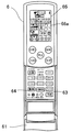
図6はリモコンの開閉カバーを閉じた状態の平面図、図7はリモコンの開閉カバーを開けた状態の平面図である。リモコン6には、図6及び図7に示すように、上部に液晶表示部66が設けられ、下部にヒンジ式のカバー61が開閉自在に設けられている。カバー61自体には図6に示すように、風集中ボタン62とお知らせボタン65が設けられており、風集中ボタン62を押すと、部屋で人が集中するエリアを探し出し、そのエリアを局所的に急速に空調する機能が働くようになっている。お知らせボタン65を押すと、押す度にリモコン6の液晶画面66の日文字表示部(7セグメント表示部)66aに表示される内容が変更されるようになっている。また、図7に示すように、カバー61を開くと露出する部分には、位置確認ボタン63と警備ボタン64が設けられている。位置確認ボタン64を押すと、ユーザーが任意に距離画像センサー2による検出を開始させることができるようになっている。警備ボタン64を押すと、ユーザーが任意に距離画像センサー2による検出を開始させることができるようになっている。
6 is a plan view of the remote control with the open / close cover closed, and FIG. 7 is a plan view of the remote control with the open / close cover opened. As shown in FIGS. 6 and 7, the
次に、以上のように構成された空気調和機を、距離画像センサーにより検出された画像及び距離データに基づく制御について具体的な実施形態を挙げて説明する。 Next, the air conditioner configured as described above will be described with reference to a specific embodiment for control based on the image detected by the distance image sensor and the distance data.
<第1の実施形態>
第1の実施形態について図8を参照して説明する。図8は第1の実施形態を表すフローチャートである。まず、工事業者が室内機1を部屋の一つの壁面に設置し、電源を入れる(ステップS101)。すると、距離画像センサー2が働き(ステップS102)、CCDの1素子毎の距離を測定する。画像制御マイコン4は、それに基づき、対向壁までの距離、天井までの距離、床までの距離、左右壁までの距離を測定し、部屋の大きさ、自分のポジションを推定する(ステップS103)。そして、室内制御マイコン5は、室内機1の設置位置と設置空間に適した室内ファン109の回転数を決定する(ステップS104)。なお、この上記の動きは、あくまでも元に記憶したデータがない場合を示しており、下記に記述してあるように、位置確認ボタンを押したり、上記の一連の作業が終わり、位置データを記憶した後で、停電が起こった場合や、運転停止時から再び運転ONした場合は、記憶データが優先され、上記のような作業は行われない。
<First Embodiment>
A first embodiment will be described with reference to FIG. FIG. 8 is a flowchart showing the first embodiment. First, the construction contractor installs the indoor unit 1 on one wall surface of the room and turns on the power (step S101). Then, the
第1の実施形態によると、室内ファン109の定格回転数の範囲内で、部屋の大きさに最適な回転数に設定することができる。
According to the first embodiment, it is possible to set the rotation speed optimum for the size of the room within the range of the rated rotation speed of the
<第2の実施形態>
第2の実施形態について図9を参照して説明する。図9は第2の実施形態を表すフローチャートである。この図において、ステップS201〜S203の工程は、上記第1の実施形態のステップS101〜S103(図3)の工程と同一であるため重複説明を省く。
<Second Embodiment>
A second embodiment will be described with reference to FIG. FIG. 9 is a flowchart showing the second embodiment. In this figure, the steps S201 to S203 are the same as the steps S101 to S103 (FIG. 3) of the first embodiment, and therefore redundant description is omitted.
ここで、リモコン6の位置確認ボタン63を押して(ステップS204)、一定時間後(ここでは10秒後とする)の画素毎の距離を測定して、その距離データは、固定物(人物ではない)として登録し、新たに先ほど行ったそれぞれの床・天井・壁までの距離を登録し直す(ステップS205)。なお、一定時間後(10秒後)にしたのは、ボタンを押してすぐに形状認識を行なうと、ユーザー自身を固定物として判定する恐れがあるために、時間差を持ってその間にユーザーにセンサー感知範囲から出てもらうためである。なお、その時に、10秒間の間は「ジー」、位置記憶する事には「カシャ」などの音を出すことにより、よりユーザーが安心して作業を行うことができる。また、時間差は10秒間に限られず、1秒間〜1分間の間で任意に設定できる。そして、室内制御マイコン5は、室内機1の設置位置と設置空間に適した室内ファン109の回転数を決定する(ステップS206)。
Here, the
第2の実施形態によると、室内ファン109の定格回転数の範囲内で、部屋の大きさに最適な回転数を任意のタイミングで決定して更新することができる。この実施形態は、部屋の模様替えにより部屋の家具のレイアウトが変更されたときなどに特に有用である。
According to the second embodiment, within the range of the rated rotational speed of the
<第3の実施形態>
第3の実施形態について図10を参照して説明する。図10は第3の実施形態を表すフローチャートである。この図において、ステップS301〜S305の工程は、上記第2の実施形態のステップS201〜S205(図9)の工程と同一であるため重複説明を省く。
<Third Embodiment>
A third embodiment will be described with reference to FIG. FIG. 10 is a flowchart showing the third embodiment. In this figure, the steps S301 to S305 are the same as the steps S201 to S205 (FIG. 9) of the second embodiment, and therefore redundant description is omitted.
ここで、室内制御マイコン5は、対向壁及び左右の壁までの距離データに基づき、室内機1がどの位置に設置されているか計算して、部屋の中心を特定し(ステップS306)、室内ファン109の回転数及び左右ルーバー7の位置を調整して部屋の中心に向かって冷風を送風する(ステップS307)。
Here, the
第3の実施形態によると、部屋の中心部に向かって空調を行なうことにより、効率的に部屋を冷房又は暖房することができる。 According to the third embodiment, the room can be efficiently cooled or heated by performing air conditioning toward the center of the room.
<第4の実施形態>
第4の実施形態について図11を参照して説明する。図11は第4の実施形態を表すフローチャートである。この図において、ステップS401〜S405の工程は、上記第2の実施形態のステップS201〜S205(図9)の工程と同一であるため重複説明を省く。
<Fourth Embodiment>
A fourth embodiment will be described with reference to FIG. FIG. 11 is a flowchart showing the fourth embodiment. In this figure, the steps S401 to S405 are the same as the steps S201 to S205 (FIG. 9) of the second embodiment, and a duplicate description is omitted.
ここで、室内制御マイコン5は、対向壁及び左右の壁までの距離データに基づき、室内機1がどの位置に設置されているか計算して、部屋の中心を特定する(ステップS406)。室内ファン109の回転数及び左右ルーバー7の位置を調整して部屋の中心に向かって冷風を送風する(ステップS407)。
Here, the
この時、室内制御マイコン5は、上記の距離データに基づき、部屋の大きさを概算し(ステップS406)、部屋の負荷を計算する。そして、圧縮機101の回転数の調整を行なう(ステップS407)。具体的には、FD値(表1参照)を用いてコントロールする。FD値は10段階程度あり、室温が設定温度になるに従って、FD値が下がってゆく。最大をFD=10とすれば、最小はFD=1、停止はFD=0であり、定格能力回転数はFD=6に設定してある。
At this time, the

まず、部屋の大きさに合わせて、定格能力回転数を決定する。その定格能力値が得られるような、回転数をあらかじめ記憶している計算式より導き出す。例えば、表示能力より大きい部屋と判断した場合は、FD=6の値を初期の定格能力の出る回転数より上げる。そして、信頼性の保てる最大回転数(FD=10)と上げた回転数の差を4分割にして、新たにFD=6からFD=10までの回転数テーブルを作り直すと同時に、FD=1とFD=6の回転数差を計算して、新たに、FD=1からFD=6までの回転数テーブルを作り直す(表1参照)。 First, the rated capacity rotation speed is determined according to the size of the room. The number of revolutions is derived from a calculation formula stored in advance so that the rated capacity value can be obtained. For example, when it is determined that the room is larger than the display capacity, the value of FD = 6 is increased from the rotation speed at which the initial rated capacity is obtained. Then, the difference between the maximum number of rotations (FD = 10) that can be reliably maintained and the increased number of rotations is divided into four, and a new rotation number table from FD = 6 to FD = 10 is newly created, and at the same time, FD = 1. The rotational speed difference of FD = 6 is calculated, and a new rotational speed table from FD = 1 to FD = 6 is recreated (see Table 1).
また、逆に部屋が小さいと判断した場合、FD=6の回転数をその能力値と合うように設定する。そうして、信頼性を保てる最小回転数(FD=1)との差を計算して、新たにFD=1からFD=6までの回転数テーブルを作成すると同時に、最大回転数(FD=10)とFD=6の差を計算して、新たにFD=6からFD=10の回転数テーブルを作成し、圧縮機100の回転数テーブルの調整を行なう。但し、余りにも、部屋が大きすぎる場合や、小さすぎる場合は、極端に部屋が大きすぎれば、FD=1とFD=6の差が開きすぎて、その時のコントロール粗すぎてしまうし、部屋が極端に小さいと、今度はFD=10とFD=6でのコントロールが回転数の差が大きすぎて粗くなるので、限度がある。その限度は、だいたい初期の回転数テーブルでのFD=7の回転数から、FD=5の回転数の間までが妥当と思われ、FD=6の回転数の調整はそれ以上の調整は行なわない。 On the other hand, when it is determined that the room is small, the rotational speed of FD = 6 is set to match the ability value. Then, a difference from the minimum number of rotations (FD = 1) that can maintain reliability is calculated, and a new rotation number table from FD = 1 to FD = 6 is created, and at the same time, the maximum number of rotations (FD = 10). ) And FD = 6, a new rotational speed table of FD = 6 to FD = 10 is created, and the rotational speed table of the compressor 100 is adjusted. However, if the room is too large or too small, if the room is too large, the difference between FD = 1 and FD = 6 will be too wide and the control at that time will be too coarse, If it is extremely small, there is a limit because the control at FD = 10 and FD = 6 becomes rough because the difference in rotational speed is too large. The limit seems to be reasonable between the rotational speed of FD = 7 in the initial rotational speed table and the rotational speed of FD = 5, and adjustment of the rotational speed of FD = 6 is performed further. Absent.
第4の実施形態によると、部屋の大きさが分かるので、圧縮機の回転数をその部屋の負荷に合うように変更することにより、きめ細かく部屋を空調することが可能となる。 According to the fourth embodiment, since the size of the room is known, it is possible to finely air-condition the room by changing the rotation speed of the compressor so as to match the load of the room.
<第5の実施形態>
第5の実施形態について図12を参照して説明する。図12は第5の実施形態を表すフローチャートである。図12に示すように、空気調和機の冷房運転を開始すると(ステップS501)、距離画像センサー2による検出を開始する(ステップS502)。具体的には、室内機1から部屋の天井、対向壁及び左右壁までの距離を画像制御マイコン4で測定し、その距離データが記憶される(ステップS503)。そして、これらの距離データを特定し(S504)、室内ファン109の回転数及び左右ルーバー7及び上下ルーバー8の位置を調整する(ステップS505)。
<Fifth Embodiment>
A fifth embodiment will be described with reference to FIG. FIG. 12 is a flowchart showing the fifth embodiment. As shown in FIG. 12, when the cooling operation of the air conditioner is started (step S501), detection by the
具体的には、冷房運転の開始時に、対向壁までの距離から室内ファン109の最大風量の回転数を割り出す。そして、対向壁及び左右の壁までの距離から、室内機1がどの位置に設置されているか計算して、部屋の中心を計算し、左右ルーバー7を調整して部屋の中心に向かって冷風を約10分程度送風した後、または、設定温度に達したら天井からの距離を計算し、上下ルーバー8の角度を調整し、上向けに上下ルーバー8を向けて運転を行う。なお、この時に天井から吊るされている電灯があった場合には、そこに風が直接当たって対向壁に届かないことがないように考慮して角度を決める。また、天井との距離が約80cm以上室内機1と離れている場合(ホールなどに設置されている場合など)は天井方向に吹き上げても、コアンダ効果を得ることは困難なので、冷風を上に向けないという判断を行なう。設定温度に達した場合は、室内ファン109の回転数を落として部屋の温度を保てるように調整を行なう。なお、この時には、部屋の中心部に向かって空調を行なう事により、効率的に部屋を冷やすことができる。
Specifically, at the start of the cooling operation, the rotational speed of the maximum air volume of the
第5の実施形態によると、天井までの距離が分かり、より正確に上下方向の角度を付けること及び風量を合わせることができ、冷房運転時に室温が設定温度付近に達したとき、コアンダ効果により冷気のシャワーが降ってくるような状態を作り出すことが可能となる。 According to the fifth embodiment, the distance to the ceiling can be known, the angle in the vertical direction can be more accurately adjusted, and the air volume can be adjusted. When the room temperature reaches around the set temperature during cooling operation, It is possible to create a state where the shower of a person falls.
<第6の実施形態>
第6の実施形態について図13を参照して説明する。図13は第6の実施形態を表すフローチャートである。図13に示すように、空気調和機の暖房運転を開始すると(ステップS601)、距離画像センサー2による検出を開始する(ステップS602)。具体的には、室内機1から部屋の床面、対向壁及び左右壁の各壁までの距離を画像制御マイコン4で測定し、その距離データが記憶される(ステップS603)。そして、これらの距離データを特定し(S604)、暖房運転時に壁面に沿って床面まで届いて床面を最適に暖めるように、室内ファン109の回転数及び左右ルーバー7及び上下ルーバー8の位置を調整する(ステップS605)。
<Sixth Embodiment>
A sixth embodiment will be described with reference to FIG. FIG. 13 is a flowchart showing the sixth embodiment. As shown in FIG. 13, when the heating operation of the air conditioner is started (step S601), detection by the
具体的には、暖房運転の開始時に、対向壁までの距離から室内ファン109の最大風量の回転数を割り出す。そして、対向壁及び左右の壁までの距離から、室内機1がどの位置に設置されているか計算して、部屋の中心を計算し、左右ルーバー7を調整して部屋の中心に向かって温風を約10分程度送風した後、または、設定温度に達したら床面からの距離を計算し、上下ルーバー8の角度を調整し、下向けに上下ルーバー8を向けて運転を行う。なお、この時にまた、下に家具があった場合には、風が家具に当たって、床まで流れないことがないように考慮して角度を決める。設定温度に達した場合は、室内ファン109の回転数を落として部屋の温度を保てるように調整を行なう。なお、この時には、部屋の中心部に向かって空調を行なう事により、効率的に部屋を暖めることができる。
Specifically, when the heating operation is started, the rotation speed of the maximum air volume of the
第6の実施形態によると、床面までの距離がわかり、より正確に上下方向の角度を付けること及び風量を合わせることができ、暖房運転時に温風を床面に貼り付けるように吹き出すことができる。 According to the sixth embodiment, the distance to the floor can be known, the angle in the vertical direction can be more accurately set, and the air volume can be adjusted, and the hot air can be blown out to stick to the floor during heating operation. it can.
<第7の実施形態>
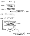
第7の実施形態について図14を参照して説明する。図14は第7の実施形態を表すフローチャートである。この図において、ステップS701〜S707の工程は、上記第4の実施形態のステップS401〜S407(図11)の工程と同一であるため重複説明を省略する。
<Seventh Embodiment>
A seventh embodiment will be described with reference to FIG. FIG. 14 is a flowchart showing the seventh embodiment. In this figure, the steps S701 to S707 are the same as the steps S401 to S407 (FIG. 11) of the fourth embodiment, and a duplicate description is omitted.
ここで、室内制御マイコン5は、距離画像センサー2により検出された画素毎の測定対象物までの距離データを、記憶した固定物の距離データと比較してそのデータとずれた場所が発生した場合に、そこに人がいると判断する(ステップS708)。その人の近くに冷風及び温風を向けてその人の温度環境が良くなるように、室内ファン109の回転数及び左右ルーバー7及び上下ルーバー8の位置を調整する(ステップS709)。
Here, the
第7の実施形態によると、スポット空調のような制御ができるため、人のいる環境がより心地良くなるように空調することができる。 According to the seventh embodiment, since control such as spot air conditioning can be performed, air conditioning can be performed so that the environment in which people are present becomes more comfortable.
<第8の実施形態>
第8の実施形態について図15を参照して説明する。図15は第8の実施形態を表すフローチャートである。この図において、ステップS801〜S809の工程は、上記第7の実施形態のステップS701〜S709(図14)の工程と同一であるため重複説明を省略する。
<Eighth Embodiment>
The eighth embodiment will be described with reference to FIG. FIG. 15 is a flowchart showing the eighth embodiment. In this figure, the steps S801 to S809 are the same as the steps S701 to S709 (FIG. 14) of the seventh embodiment, and a duplicate description is omitted.
ここで、室内制御マイコン5は、一旦人と判断された測定対象物が、ある一定時間到達しても距離データが変わらないとき、家具などの動かない物と判断して、人としての判定を中止する(ステップS810)。
Here, the
第8の実施形態によると、家具などを部屋に運んできた際に、距離画像センサーが反応して人と認識してしまったものに対しても、動かない物として認識を変更することが可能となる。よって、人と静物を識別することが可能になり、より正確な空調を行うことが可能となる。 According to the eighth embodiment, it is possible to change the recognition as a non-moving object even if the distance image sensor reacts and recognizes a person when carrying furniture or the like to the room. It becomes. Therefore, it becomes possible to distinguish a person and a still life and to perform more accurate air conditioning.
<第9の実施形態>
第9の実施形態について図16を参照して説明する。図16は第9の実施形態を表すフローチャートである。この図において、ステップS901〜S908の工程は、上記第7の実施形態のステップS701〜S708(図14)の工程と同一であるため重複説明を省略する。
<Ninth Embodiment>
A ninth embodiment will be described with reference to FIG. FIG. 16 is a flowchart showing the ninth embodiment. In this figure, the steps S901 to S908 are the same as the steps S701 to S708 (FIG. 14) of the seventh embodiment, and the duplicated explanation is omitted.
ここで、室内制御マイコン5は、人と判定された測定対象物の形状認識を行い、子供か大人かを判断し(ステップS909)、大人と判断した場合には、風をその人の周りに集中させ、子供の場合は、直接当てずにやや離れた所に風を向けるように、左右ルーバー7及び上下ルーバー8の位置及び室内ファン109の回転数を調整する(ステップS910、S911)。
Here, the
そして、室内制御マイコン5は、一旦人と判定された測定対象物が、ある一定時間到達しても距離データが変わらないとき、家具などの動かない物と判断して、人としての判定を中止する(ステップS912、S913)。
Then, the
第9の実施形態によると、大人と子供を識別することが可能となり、より体温の奪われやすい子供の場合は、大人よりも広範囲に送風することにより、子供の周囲温度が緩和された状態で変化していくので、子供が環境変化に対応しやすくなる。 According to the ninth embodiment, an adult and a child can be distinguished, and in the case of a child whose body temperature is more easily lost, the ambient temperature of the child is reduced by blowing air over a wider range than the adult. Because it changes, it becomes easier for children to respond to environmental changes.
<第10の実施形態>
第10の実施形態について図17を参照して説明する。図17は第10の実施形態を表すフローチャートである。この図において、ステップS1001〜S1008の工程は、上記第7の実施形態のステップS701〜S708(図14)の工程と同一であるため重複説明を省略する。
<Tenth Embodiment>
A tenth embodiment will be described with reference to FIG. FIG. 17 is a flowchart showing the tenth embodiment. In this figure, the steps S1001 to S1008 are the same as the steps S701 to S708 (FIG. 14) of the seventh embodiment, and the duplicate description is omitted.
ここで、室内制御マイコン5は、リモコン6の風集中ボタン62が押されると(ステップS1010)、人と判定された測定対象物に風を直接当てるように、左右ルーバー7及び上下ルーバー8の位置が調整される(ステップS1011)。
Here, when the
風集中ボタン62が押されなかったときは、人と判定された測定対象物の形状認識を行い、子供か大人かを判断し(S1012)、大人と判断した場合には、風をその人の周りに集中させ、子供の場合は、直接当てずにやや離れた所に風を向けるように、左右ルーバー7及び上下ルーバー8の位置及び室内ファン109の回転数を調整する(ステップS1013、S1014)。
When the
そして、室内制御マイコン5は、一旦人と判定された測定対象物が、ある一定時間到達しても距離データが変わらないとき、家具などの動かない物と判断して、人としての判定を中止する(ステップS1015、S1016)。
Then, the
第10の実施形態によると、部屋で人が移動しても、人に追随してその人に直接向かって集中して送風することができる。 According to the tenth embodiment, even if a person moves in the room, it is possible to follow the person and concentrate the air directly toward the person.
<第11の実施形態>
第11の実施形態について図18を参照して説明する。図18は第11の実施形態を表すフローチャートである。この図において、ステップS1101〜S1108の工程は、上記第7の実施形態のステップS701〜S707(図14)の工程と同一であるため重複説明を省略する。
<Eleventh embodiment>
The eleventh embodiment will be described with reference to FIG. FIG. 18 is a flowchart showing the eleventh embodiment. In this figure, the steps S1101 to S1108 are the same as the steps S701 to S707 (FIG. 14) of the seventh embodiment, and a duplicate description is omitted.
ここで、室内制御マイコン5は、距離画像センサー2により検出された画素毎の測定対象物までの距離データを、記憶した固定物の距離データと比較してそのデータとずれた場所が発生した場合に、そこに人がいると判断し、人が何人いるか(人数)を判定する(ステップS1108)。人数が1人のときには、リモコンの風集中ボタン62が押されると(ステップS1110)、風を直接人に当てるように、左右ルーバー7及び上下ルーバー8の位置が変更される(ステップS1111)。ステップS1108で人数が2人以上であれば、2人か3人以上かをさらに判定し(ステップS1117)2人であればその間に送風するように、左右ルーバー7及び上下ルーバー8の位置が変更され(ステップS1118)、3人以上であればステップS1107に戻り、部屋の中心に向けて送風するようにする。なお、この時に風集中ボタン62を押しても対応できないので、反応しないか、ブザー音を出してユーザーに拒否していることを報知する。または、リモコン6の液晶画面66に風集中ランプ(不図示)を設けて、その時には5秒間点滅した後に、消灯する。
Here, the
風集中ボタン62が押されなかったときは、人と判定された測定対象物の形状認識を行い、子供か大人かを判断し(S1112)、大人と判断した場合には、風をその人の周りに集中させ、子供の場合は、直接当てずにやや離れた所に風を向けるように、左右ルーバー7及び上下ルーバー8の位置及び室内ファン109の回転数を調整する(ステップS1113、S1114)。
When the
そして、室内制御マイコン5は、一旦人と判定された測定対象物が、ある一定時間到達しても距離データが変わらないとき、家具などの動かない物と判断して、人としての判定を中止する(ステップS1115、S1116)。
Then, the
第11の実施形態によると、部屋にいる人の人数が2人の時に、その間に送風するようにすることで、2人を包み込むように効率よく空調することができる。 According to the eleventh embodiment, when the number of people in the room is two, the air can be efficiently air-conditioned so as to wrap up two people by blowing air between them.
<第12の実施形態>
第12の実施形態について図19を参照して説明する。図19は第12の実施形態を表すフローチャートである。この図において、ステップS1101〜S1108の工程は、上記第7の実施形態のステップS701〜S707(図14)の工程と同一であるため重複説明を省略する。
<Twelfth Embodiment>
A twelfth embodiment will be described with reference to FIG. FIG. 19 is a flowchart showing the twelfth embodiment. In this figure, the steps S1101 to S1108 are the same as the steps S701 to S707 (FIG. 14) of the seventh embodiment, and a duplicate description is omitted.
ここで、室内制御マイコン5は、距離画像センサー2により検出された画素毎の測定対象物までの距離データを、記憶した固定物の距離データと比較してそのデータとずれた場所が発生した場合に、そこに人がいると判断し、人の人数が所定時間後増えたか否かを判定する(ステップS1208)。そして、人数が増えた場合は圧縮機101の回転数を減少させ(ステップS1209)、人数が減った場合は圧縮機101の回転数を増大させる(ステップS1210)。なお、暖房運転の場合は、ステップS1209、S1210の圧縮回転数の制御は逆になり、人数が増えた場合は圧縮機101の回転数を増大させ、人数が減った場合は圧縮機101の回転数を減少させる。
Here, the
具体的には、冷房運転では、人が部屋の中に入ってきた場合に、2人の場合にはFD値を1段階、4人の場合は2段階、室温が変化する前に上げる。すなわち、FD値を1人につき0.5段階上げる。暖房運転では、部屋に3人以上入ってきたら、FD値を1つ下げる。6人以上入ってきたら、FD値を2段階下げる。なお、FD値の上げ下げの値は、空気調和機の能力により違うので、一例である。このようにすることにより、部屋の温度の乱れを最小限に食い止めることができる。なお、熱負荷条件により、それでも室温が乱れた場合には、通常のフィードバック制御によりコントロールすれば即座に対応できる。 Specifically, in the cooling operation, when a person enters the room, the FD value is increased by one level in the case of two persons and in two stages in the case of four persons before the room temperature changes. That is, the FD value is increased by 0.5 level per person. In heating operation, if 3 or more people enter the room, the FD value is lowered by one. If 6 or more people enter, lower the FD value by two levels. In addition, since the value of raising / lowering of FD value changes with the capability of an air conditioner, it is an example. By doing so, it is possible to minimize the disturbance of the room temperature. If the room temperature is still disturbed due to the heat load condition, it can be dealt with immediately by controlling it with normal feedback control.
なお、リモコン6のお知らせボタン65を押すたびに、図20に示すように、リモコン6の液晶画面66の日文字表示部66aに表示される内容を逐次変更させて室内機1が認識している人数を確認できるようにすれば、こうする事により、ユーザーが距離画像センサー2が働いているかどうかを確認することができ、無用なサービスコールをしなくて済むためユーザフレンドリーを実現できる。なお、人数を表示し何もしなければ、約10秒程度後に初期の画面に戻る。
Each time the
第12の実施形態によると、動いている測定対象物を人と判断して、人数を数え、その増減により、圧縮機101の回転数をあらかじめ調整することにより、フォワード制御によって部屋の温度の乱れを最小限に食い止めることが可能となる。
According to the twelfth embodiment, the moving object to be measured is determined to be a person, the number of persons is counted, and the number of persons is increased / decreased so that the rotation speed of the
<第13の実施形態>
第13の実施形態について図21を参照して説明する。図21は第13の実施形態を表すフローチャートである。図21に示すように、リモコン6の警備ボタン65を押すと(ステップS1301)、そのボタンを押して1分後から空気調和機が運転停止中であっても警備モードに入り、距離画像センサー2による検出が開始される(ステップS1302)。赤外線を使用しているので、警備モードが作動していても一般人には分からない。なお、警備ボタンは室内機1本体に設けてもよい。
<13th Embodiment>
A thirteenth embodiment will be described with reference to FIG. FIG. 21 is a flowchart showing the thirteenth embodiment. As shown in FIG. 21, when the
具体的には、室内機1から部屋の対向壁及び左右壁の各壁までの距離を画像制御マイコン4で測定し、その距離データが記憶される(ステップS1303)。室内制御マイコン5は、室内制御マイコン5は、距離画像センサー2により検出された画素毎の測定対象物までの距離データを、記憶した固定物の距離データと比較してそのデータとずれた場所が発生した場合に、侵入者がいると判断し(ステップS1304)、30秒から2分の間警告音や警告ガイダンスを流して警告を発し(ステップS1305)、リモコン6の警備ボタン65を再び押して警備モードを一定時間内に解除しない場合に(ステップS1306)、不審者侵入のメールを検知した旨のメールを携帯電話又はPCのアドレスに送信する(ステップS1307)。ステップS1306で警備モードが解除された場合は、警備モードを終了する。インターネットとの接続に関しては、直接室内機と接続しなくても、外部の機器を中継器として繋いで、インターネットと接続する構成でもよい。
Specifically, the distance from the indoor unit 1 to the opposite walls and the left and right walls of the room is measured by the
第13の実施形態によると、侵入者を見張るセキュリティー機能を空気調和機に付加することができる。 According to the thirteenth embodiment, it is possible to add a security function for watching an intruder to the air conditioner.
<第14の実施形態>
第14の実施形態について図22を参照して説明する。図22は第14の実施形態を表すフローチャートである。この図において、ステップS1401〜S1408の工程は、上記第7の実施形態のステップS701〜S707(図14)の工程と同一であるため重複説明を省略する。
<Fourteenth embodiment>
A fourteenth embodiment will be described with reference to FIG. FIG. 22 is a flowchart showing the fourteenth embodiment. In this figure, the steps S1401 to S1408 are the same as the steps S701 to S707 (FIG. 14) of the seventh embodiment, so that the duplicated explanation is omitted.
ここで、室内制御マイコン5は、室温が設定温度に達してから1時間経過しても、部屋に人がいると判断されない場合には(ステップS1408)、設定温度を自動的に緩めて省エネ運転を行う(ステップS1409)。このとき例えば、冷房運転時ならば、室温を2℃上げる。また、人を感知したら、再び設定温度を元に戻し、人の人数が所定時間後増えたか否かを判定する(ステップS1410)。そして、人数が増えた場合は圧縮機101の回転数を減少させ(ステップS1411)、人数が減った場合は圧縮機101の回転数を増大させる(ステップS1412)。なお、暖房運転の場合は、ステップS1406の設定温度の制御は逆になり、設定温度を下げるように制御され、ステップS1411、S1412の圧縮回転数の制御も逆になり、人数が増えた場合は圧縮機101の回転数を増大させ、人数が減った場合は圧縮機101の回転数を減少させる。
Here, if the
第14の実施形態によると、部屋に人がいないと判断した場合には、設定温度を下げて省エネ運転を行うことが可能となる。 According to the fourteenth embodiment, when it is determined that there is no person in the room, it is possible to perform the energy saving operation by lowering the set temperature.
<第15の実施形態>
第15の実施形態について図23を参照して説明する。図23は第15の実施形態を表すフローチャートである。この図において、ステップS1501〜S1507の工程は、上記第7の実施形態のステップS701〜S707(図14)の工程と同一であるため重複説明を省略する。
<Fifteenth embodiment>
A fifteenth embodiment will be described with reference to FIG. FIG. 23 is a flowchart showing the fifteenth embodiment. In this figure, the steps S1501 to S1507 are the same as the steps S701 to S707 (FIG. 14) of the seventh embodiment, so that the duplicated explanation is omitted.
ここで、室内制御マイコン5は、室温が設定温度に達してから1時間経過しても、部屋に人がいると判断されない場合には(ステップS1408)、例えば電流検知を行なって電流量を半分程度に抑制して省エネ運転を行うように、圧縮機101の回転数を低減する(ステップS1509)。また、人を感知したら、再び設定温度を元に戻し、人の人数が所定時間後増えたか否かを判定する(ステップS1410)。そして、人数が増えた場合は圧縮機101の回転数を減少させ(ステップS1411)、人数が減った場合は圧縮機101の回転数を増大させる(ステップS1412)。なお、暖房運転の場合は、ステップS1406の設定温度の制御は逆になり、設定温度を下げるように制御され、ステップS1411、S1412の圧縮回転数の制御も逆になり、人数が増えた場合は圧縮機101の回転数を増大させ、人数が減った場合は圧縮機101の回転数を減少させる。
Here, if the
第15の実施形態によると、部屋に人がいないと判断した場合には、電流量すなわち、消費電力を抑えることにより、省エネ運転を行うことが可能となる。 According to the fifteenth embodiment, when it is determined that there is no person in the room, it is possible to perform an energy saving operation by suppressing the amount of current, that is, power consumption.
<第16の実施形態>
第16の実施形態について図24を参照して説明する。図24は第16の実施形態を表すフローチャートである。この図において、ステップS1601〜S1607の工程は、上記第7の実施形態のステップS701〜S706(図14)の工程と同一であるため重複説明を省略する。
<Sixteenth Embodiment>
A sixteenth embodiment will be described with reference to FIG. FIG. 24 is a flowchart showing the sixteenth embodiment. In this figure, the steps S1601 to S1607 are the same as the steps S701 to S706 (FIG. 14) of the seventh embodiment, and the duplicate description is omitted.
ここで、室内制御マイコン5は、距離画像センサー2により検出された画素毎の測定対象物までの距離データにより、室内機1の前方に照明や、エアコン下方にタンスなどの障害物を検知した時には(ステップS1607)、障害物を避けるように、左右ルーバー7及び上下ルーバー8の角度にマスク(その角度で止まって運転しない)をかける(ステップS1608)。
Here, when the
ステップS1607で障害物を検知しないときは、部屋の中心位置に向けて送風するように、室内ファン109の回転数及び左右ルーバー7及び上下ルーバー8の位置を調整するとともに、部屋の大きさを特定し、各段階へ割り振られる圧縮機101の回転数の値を部屋の大きさに合わせて変更する(ステップS1609)。
If no obstacle is detected in step S1607, the rotational speed of the
そして、室内制御マイコン5は、設定温度に達してからある1時間経過しても、人を認識できない場合には(ステップS1610)、電流検知を行なって電流量を半分程度に抑制して省エネ運転を行うように、前記圧縮機の回転数を低減する(ステップS1611)。また、人を感知したら、再び設定温度を元に戻し、人の人数が所定時間後増えたか否かを判定する(ステップS1612)。そして、人数が増えた場合は圧縮機101の回転数を減少させ(ステップS1613)、人数が減った場合は圧縮機101の回転数を増大させる(ステップS1614)。なお、暖房運転の場合は、ステップS1606の設定温度の制御は逆になり、設定温度を下げるように制御され、ステップS1411、S1412の圧縮回転数の制御も逆になり、人数が増えた場合は圧縮機101の回転数を増大させ、人数が減った場合は圧縮機101の回転数を減少させる。
If the
第16の実施形態によると、障害物に風の流れを乱されて、空調が妨げられるのを自動的に回避することができる。 According to the sixteenth embodiment, it is possible to automatically prevent the airflow from being disturbed by the disturbance of the wind flow by the obstacle.
本発明は、空気調和機に利用することができる。 The present invention can be used for an air conditioner.
1 室内機
2 距離画像センサー
4 画像処理マイコン
5 室内制御マイコン
6 リモコン
62 風集中ボタン
63 位置確認ボタン
64 警備ボタン
65 お知らせボタン
66 液晶画面
7 左右ルーバー
8 上下ルーバー
101 圧縮機
109 室内ファン
DESCRIPTION OF SYMBOLS 1
Claims (6)
前記吹出口に設けられて前記吹出口から吹き出される空気の風向を変更するルーバーと、
前記室内機の本体の前面に設けられ、画素毎に光源から投射されたパルス光が測定対象物により反射してきたときの遅れ時間を測定することにより測定対象物までの距離を検出する距離画像センサーと、
を備え、前記距離画像センサーにより検出された画素毎の測定対象物までの距離データに基づいて、前記室内機の設置位置と設置空間に適した前記室内ファンの回転数または前記ルーバーの位置を決定し、
前記距離画像センサーにより検出された距離データに基づいて人と判定された測定対象物までの距離データが一定時間経過しても変わらないときに、人と判定された測定対象物について人と判定することを中止することを特徴とする空気調和機。 An indoor heat exchanger provided in the indoor unit, a compressor provided in the outdoor unit that can control the rotation speed, and a switching means that changes the flow of the refrigerant between the cooling operation and the heating operation are provided by a refrigerant circuit that circulates the refrigerant. having a refrigeration cycle which is connected, provided the number of rotation mutable indoor fan on the indoor unit, the air conditioner blows are harmonized Nde write breathe room air the air from the air outlet to the room,
A louver provided at the air outlet to change the air direction of the air blown from the air outlet;
Distance image sensor that detects the distance to the object of measurement by measuring the delay time of when the provided on the front surface of the indoor unit body, a pulse light projected from the light source has been reflected by the measurement object for each pixel When,
And determining the installation position of the indoor unit and the rotation speed of the indoor fan or the position of the louver suitable for the installation space based on the distance data to the measurement object for each pixel detected by the distance image sensor And
When the distance data to the measurement object determined to be a person based on the distance data detected by the distance image sensor does not change even after a certain period of time, the measurement object determined to be a person is determined to be a person. An air conditioner characterized by stopping the operation.
前記吹出口に設けられて前記吹出口から吹き出される空気の風向を変更するルーバーと、
前記室内機の本体の前面に設けられ、画素毎に光源から投射されたパルス光が測定対象物により反射してきたときの遅れ時間を測定することにより測定対象物までの距離を検出する距離画像センサーと、
を備え、前記距離画像センサーにより検出された画素毎の測定対象物までの距離データに基づいて、前記室内機の設置位置と設置空間に適した前記室内ファンの回転数または前記ルーバーの位置を決定し、
前記距離画像センサーにより検出された距離データに基づいて測定対象物が人か否かを判定するとともに、人と判定された測定対象物の形状認識を行うことによって子供か大人かを判断し、
大人と判断した場合には風をその人の周りに集中させ、子供と判断した場合には風を直接当てないようにすることを特徴とする空気調和機。 An indoor heat exchanger provided in the indoor unit, a compressor provided in the outdoor unit that can control the rotation speed, and a switching means that changes the flow of the refrigerant between the cooling operation and the heating operation are provided by a refrigerant circuit that circulates the refrigerant. In the air conditioner having a connected refrigeration cycle, providing an indoor fan capable of changing the number of rotations in the indoor unit, and sucking air in the room and blowing out conditioned air from the outlet to the room,
A louver provided at the air outlet to change the air direction of the air blown from the air outlet;
A distance image sensor that is provided on the front surface of the main body of the indoor unit and detects a distance to the measurement object by measuring a delay time when the pulsed light projected from the light source is reflected by the measurement object for each pixel. When,
And determining the installation position of the indoor unit and the rotation speed of the indoor fan or the position of the louver suitable for the installation space based on the distance data to the measurement object for each pixel detected by the distance image sensor And
Determining whether the measurement object is a person based on the distance data detected by the distance image sensor, and determining whether the measurement object is a person or not by determining the shape of the measurement object determined as a person,
An air conditioner characterized by concentrating the wind around the person when judged as an adult and not directing the wind when judged as a child .
前記距離画像センサーにより検出した天井までの距離データ、床までの距離データ、左右壁までの距離データ、及び対向壁までの距離データに基づいて前記部屋の大きさを特定し、各段階へ割り振られる前記圧縮機の回転数の値を前記部屋の大きさに合わせて決定することを特徴とする請求項1〜4のいずれかに記載の空気調和機。 The control of the rotational speed of the compressor is to select one from a rotational speed group assigned to a predetermined number of stages,
Based on the distance data to the ceiling, the distance data to the floor, the distance data to the left and right walls, and the distance data to the opposite wall detected by the distance image sensor, the size of the room is specified and assigned to each stage. The air conditioner according to any one of claims 1 to 4, wherein a value of a rotation speed of the compressor is determined according to a size of the room .
冷房運転時に前記部屋の天井までの距離データが所定値未満の場合には前記上下ルーバーによって前記吹出口から上方向に空気を送出し、When the distance data to the ceiling of the room during cooling operation is less than a predetermined value, air is sent upward from the outlet through the upper and lower louvers,
前記天井までの距離データが所定値以上の場合には前記吹出口から上方向に空気を送出しないことを特徴とする請求項1〜請求項5のいずれかに記載の空気調和機。The air conditioner according to any one of claims 1 to 5, wherein when the distance data to the ceiling is equal to or greater than a predetermined value, air is not sent upward from the air outlet.
Priority Applications (1)
| Application Number | Priority Date | Filing Date | Title |
|---|---|---|---|
| JP2007315456A JP5112031B2 (en) | 2007-12-06 | 2007-12-06 | Air conditioner |
Applications Claiming Priority (1)
| Application Number | Priority Date | Filing Date | Title |
|---|---|---|---|
| JP2007315456A JP5112031B2 (en) | 2007-12-06 | 2007-12-06 | Air conditioner |
Publications (3)
| Publication Number | Publication Date |
|---|---|
| JP2009139010A JP2009139010A (en) | 2009-06-25 |
| JP2009139010A5 JP2009139010A5 (en) | 2010-07-08 |
| JP5112031B2 true JP5112031B2 (en) | 2013-01-09 |
Family
ID=40869790
Family Applications (1)
| Application Number | Title | Priority Date | Filing Date |
|---|---|---|---|
| JP2007315456A Expired - Fee Related JP5112031B2 (en) | 2007-12-06 | 2007-12-06 | Air conditioner |
Country Status (1)
| Country | Link |
|---|---|
| JP (1) | JP5112031B2 (en) |
Cited By (1)
| Publication number | Priority date | Publication date | Assignee | Title |
|---|---|---|---|---|
| CN109477655B (en) * | 2016-08-08 | 2021-04-20 | 三菱电机株式会社 | Air conditioner |
Families Citing this family (37)
| Publication number | Priority date | Publication date | Assignee | Title |
|---|---|---|---|---|
| JP5175562B2 (en) * | 2008-01-28 | 2013-04-03 | シャープ株式会社 | Person position detection device and air conditioner |
| JP5126189B2 (en) * | 2009-09-29 | 2013-01-23 | パナソニック株式会社 | Air conditioner |
| JP5487869B2 (en) * | 2009-10-06 | 2014-05-14 | パナソニック株式会社 | Air conditioner |
| JP5402488B2 (en) * | 2009-10-07 | 2014-01-29 | パナソニック株式会社 | Air conditioner |
| JP5402487B2 (en) * | 2009-10-07 | 2014-01-29 | パナソニック株式会社 | Air conditioner |
| JP2011117627A (en) * | 2009-12-01 | 2011-06-16 | Mitsubishi Electric Corp | Air conditioner |
| JP5306168B2 (en) * | 2009-12-24 | 2013-10-02 | 三菱電機株式会社 | Air conditioner |
| JP2012057826A (en) * | 2010-09-06 | 2012-03-22 | Sharp Corp | Controller and air conditioner |
| JP5984453B2 (en) * | 2012-01-10 | 2016-09-06 | 三菱電機株式会社 | Air conditioner indoor unit |
| JP2013204835A (en) * | 2012-03-27 | 2013-10-07 | Mitsubishi Electric Corp | Air conditioner |
| JP2014020670A (en) * | 2012-07-18 | 2014-02-03 | Mitsubishi Electric Corp | Indoor unit for air conditioner |
| JP5819271B2 (en) * | 2012-09-03 | 2015-11-18 | 日立アプライアンス株式会社 | Air conditioner |
| JP2014081144A (en) * | 2012-10-17 | 2014-05-08 | Hitachi Appliances Inc | Air conditioner |
| JP6091348B2 (en) * | 2013-06-13 | 2017-03-08 | 三菱電機株式会社 | Air conditioner |
| JP2015137836A (en) * | 2014-01-24 | 2015-07-30 | 日立アプライアンス株式会社 | Air conditioner and indoor unit of the same |
| JP6271294B2 (en) * | 2014-02-26 | 2018-01-31 | シャープ株式会社 | Air conditioner |
| JP2016040495A (en) * | 2014-08-12 | 2016-03-24 | 日立アプライアンス株式会社 | Air conditioner |
| JP6408300B2 (en) * | 2014-08-22 | 2018-10-17 | 日立ジョンソンコントロールズ空調株式会社 | Air conditioner |
| JP2016057030A (en) * | 2014-09-12 | 2016-04-21 | 日立アプライアンス株式会社 | Air conditioner |
| JP6386945B2 (en) * | 2015-03-10 | 2018-09-05 | 日立ジョンソンコントロールズ空調株式会社 | Air conditioner |
| JP6444228B2 (en) * | 2015-03-17 | 2018-12-26 | 日立ジョンソンコントロールズ空調株式会社 | Air conditioner |
| JP6692134B2 (en) * | 2015-08-25 | 2020-05-13 | 日立ジョンソンコントロールズ空調株式会社 | Air conditioner |
| JP6154923B2 (en) * | 2016-02-10 | 2017-06-28 | ジョンソンコントロールズ ヒタチ エア コンディショニング テクノロジー(ホンコン)リミテッド | Air conditioner |
| JP6746202B2 (en) * | 2016-05-11 | 2020-08-26 | 日立ジョンソンコントロールズ空調株式会社 | Air conditioner |
| JP6172692B1 (en) * | 2016-05-17 | 2017-08-02 | MEi株式会社 | Air conditioner indoor unit |
| WO2018025371A1 (en) * | 2016-08-04 | 2018-02-08 | 三菱電機株式会社 | Air conditioner |
| WO2018029805A1 (en) * | 2016-08-10 | 2018-02-15 | 三菱電機株式会社 | Air conditioner indoor unit |
| EP3527904B1 (en) * | 2016-10-11 | 2021-09-22 | Mitsubishi Electric Corporation | Air conditioning apparatus |
| CN107676936A (en) * | 2017-09-30 | 2018-02-09 | 珠海格力电器股份有限公司 | The control method and device of air-conditioning equipment |
| CN109028515A (en) * | 2018-07-23 | 2018-12-18 | 广东美的制冷设备有限公司 | Control method, air conditioner and the storage medium of air conditioner |
| CN110848930A (en) * | 2019-11-07 | 2020-02-28 | 珠海格力电器股份有限公司 | Air conditioner air supply method based on binocular camera and air conditioner |
| JP2021103029A (en) * | 2019-12-25 | 2021-07-15 | パナソニックIpマネジメント株式会社 | Air cleaning system and air cleaning method |
| CN113586501B (en) * | 2020-04-30 | 2023-06-27 | 云米互联科技(广东)有限公司 | Circulation fan control method, circulation fan and computer readable storage medium |
| JPWO2022024261A1 (en) * | 2020-07-29 | 2022-02-03 | ||
| JP2022172986A (en) * | 2021-05-07 | 2022-11-17 | ダイキン工業株式会社 | Indoor unit for air conditioner |
| CN113156831B (en) * | 2021-05-24 | 2023-07-18 | 青岛海尔空调器有限总公司 | Household appliance control method and device for mosquito repelling and household appliance |
| CN115264585B (en) * | 2022-07-05 | 2023-04-11 | 曼茨环境技术有限公司 | Novel heat pump trigeminy supplies variable frequency air conditioning system |
Family Cites Families (4)
| Publication number | Priority date | Publication date | Assignee | Title |
|---|---|---|---|---|
| JPS6210538A (en) * | 1985-07-08 | 1987-01-19 | Matsushita Electric Ind Co Ltd | Device for deflecting air flow direction in air conditioner and method of deflecting air flow direction |
| JPH09145127A (en) * | 1995-11-27 | 1997-06-06 | Toshiba Corp | Air conditioner |
| JP4371990B2 (en) * | 2004-12-10 | 2009-11-25 | シャープ株式会社 | Air conditioner |
| JP2007170856A (en) * | 2005-12-19 | 2007-07-05 | Denso Corp | Distance data generating method, distance image generating apparatus and photoelectronic sensor |
-
2007
- 2007-12-06 JP JP2007315456A patent/JP5112031B2/en not_active Expired - Fee Related
Cited By (1)
| Publication number | Priority date | Publication date | Assignee | Title |
|---|---|---|---|---|
| CN109477655B (en) * | 2016-08-08 | 2021-04-20 | 三菱电机株式会社 | Air conditioner |
Also Published As
| Publication number | Publication date |
|---|---|
| JP2009139010A (en) | 2009-06-25 |
Similar Documents
| Publication | Publication Date | Title |
|---|---|---|
| JP5112031B2 (en) | Air conditioner | |
| JP6046579B2 (en) | Air conditioner | |
| JP6741050B2 (en) | Blower equipment | |
| EP2206983B1 (en) | Air conditioner and method of operating the same | |
| JP4487809B2 (en) | Air conditioner | |
| JP5300793B2 (en) | Air conditioner | |
| JP6375520B2 (en) | Air conditioner | |
| EP2206982B1 (en) | Air conditioner and method of operating the same | |
| KR20120064492A (en) | Air conditioner and method for door control of the air conditioner | |
| JP2015025564A (en) | Air conditioner | |
| JP6348763B2 (en) | Air conditioner | |
| JP5725114B2 (en) | Air conditioning system | |
| JP6905808B2 (en) | Air conditioner | |
| JP2015206483A (en) | air conditioner | |
| JP6285815B2 (en) | Air conditioner or air conditioning system | |
| JP2017187236A (en) | Air conditioner | |
| JP5677178B2 (en) | Air conditioner | |
| JP2017040407A (en) | Air conditioner | |
| KR102094221B1 (en) | Air-conditioner and Contral Method | |
| JP4983883B2 (en) | Air conditioner | |
| JP6438143B2 (en) | Air conditioner indoor unit | |
| JP2018119782A (en) | Air conditioner | |
| JP6692134B2 (en) | Air conditioner | |
| JP7301133B2 (en) | air conditioner | |
| JP2013120052A (en) | Air conditioner |
Legal Events
| Date | Code | Title | Description |
|---|---|---|---|
| A521 | Request for written amendment filed |
Free format text: JAPANESE INTERMEDIATE CODE: A523 Effective date: 20100526 |
|
| A621 | Written request for application examination |
Free format text: JAPANESE INTERMEDIATE CODE: A621 Effective date: 20100526 |
|
| A977 | Report on retrieval |
Free format text: JAPANESE INTERMEDIATE CODE: A971007 Effective date: 20111215 |
|
| A131 | Notification of reasons for refusal |
Free format text: JAPANESE INTERMEDIATE CODE: A131 Effective date: 20120327 |
|
| A521 | Request for written amendment filed |
Free format text: JAPANESE INTERMEDIATE CODE: A523 Effective date: 20120523 |
|
| TRDD | Decision of grant or rejection written | ||
| A01 | Written decision to grant a patent or to grant a registration (utility model) |
Free format text: JAPANESE INTERMEDIATE CODE: A01 Effective date: 20120918 |
|
| A01 | Written decision to grant a patent or to grant a registration (utility model) |
Free format text: JAPANESE INTERMEDIATE CODE: A01 |
|
| A61 | First payment of annual fees (during grant procedure) |
Free format text: JAPANESE INTERMEDIATE CODE: A61 Effective date: 20121010 |
|
| FPAY | Renewal fee payment (event date is renewal date of database) |
Free format text: PAYMENT UNTIL: 20151019 Year of fee payment: 3 |
|
| R150 | Certificate of patent or registration of utility model |
Ref document number: 5112031 Country of ref document: JP Free format text: JAPANESE INTERMEDIATE CODE: R150 Free format text: JAPANESE INTERMEDIATE CODE: R150 |
|
| S531 | Written request for registration of change of domicile |
Free format text: JAPANESE INTERMEDIATE CODE: R313531 |
|
| R350 | Written notification of registration of transfer |
Free format text: JAPANESE INTERMEDIATE CODE: R350 |
|
| RD03 | Notification of appointment of power of attorney |
Free format text: JAPANESE INTERMEDIATE CODE: R3D03 |
|
| LAPS | Cancellation because of no payment of annual fees |