JP2014020670A - Indoor unit for air conditioner - Google Patents
Indoor unit for air conditioner Download PDFInfo
- Publication number
- JP2014020670A JP2014020670A JP2012159540A JP2012159540A JP2014020670A JP 2014020670 A JP2014020670 A JP 2014020670A JP 2012159540 A JP2012159540 A JP 2012159540A JP 2012159540 A JP2012159540 A JP 2012159540A JP 2014020670 A JP2014020670 A JP 2014020670A
- Authority
- JP
- Japan
- Prior art keywords
- user
- face
- air
- air conditioning
- information
- Prior art date
- Legal status (The legal status is an assumption and is not a legal conclusion. Google has not performed a legal analysis and makes no representation as to the accuracy of the status listed.)
- Pending
Links
Images


Classifications
-
- F—MECHANICAL ENGINEERING; LIGHTING; HEATING; WEAPONS; BLASTING
- F24—HEATING; RANGES; VENTILATING
- F24F—AIR-CONDITIONING; AIR-HUMIDIFICATION; VENTILATION; USE OF AIR CURRENTS FOR SCREENING
- F24F11/00—Control or safety arrangements
- F24F11/30—Control or safety arrangements for purposes related to the operation of the system, e.g. for safety or monitoring
-
- F—MECHANICAL ENGINEERING; LIGHTING; HEATING; WEAPONS; BLASTING
- F24—HEATING; RANGES; VENTILATING
- F24F—AIR-CONDITIONING; AIR-HUMIDIFICATION; VENTILATION; USE OF AIR CURRENTS FOR SCREENING
- F24F1/00—Room units for air-conditioning, e.g. separate or self-contained units or units receiving primary air from a central station
- F24F1/0007—Indoor units, e.g. fan coil units
- F24F1/0043—Indoor units, e.g. fan coil units characterised by mounting arrangements
- F24F1/0057—Indoor units, e.g. fan coil units characterised by mounting arrangements mounted in or on a wall
-
- F—MECHANICAL ENGINEERING; LIGHTING; HEATING; WEAPONS; BLASTING
- F24—HEATING; RANGES; VENTILATING
- F24F—AIR-CONDITIONING; AIR-HUMIDIFICATION; VENTILATION; USE OF AIR CURRENTS FOR SCREENING
- F24F1/00—Room units for air-conditioning, e.g. separate or self-contained units or units receiving primary air from a central station
- F24F1/0007—Indoor units, e.g. fan coil units
- F24F1/0071—Indoor units, e.g. fan coil units with means for purifying supplied air
-
- F—MECHANICAL ENGINEERING; LIGHTING; HEATING; WEAPONS; BLASTING
- F24—HEATING; RANGES; VENTILATING
- F24F—AIR-CONDITIONING; AIR-HUMIDIFICATION; VENTILATION; USE OF AIR CURRENTS FOR SCREENING
- F24F11/00—Control or safety arrangements
- F24F11/62—Control or safety arrangements characterised by the type of control or by internal processing, e.g. using fuzzy logic, adaptive control or estimation of values
- F24F11/63—Electronic processing
- F24F11/64—Electronic processing using pre-stored data
-
- F—MECHANICAL ENGINEERING; LIGHTING; HEATING; WEAPONS; BLASTING
- F24—HEATING; RANGES; VENTILATING
- F24F—AIR-CONDITIONING; AIR-HUMIDIFICATION; VENTILATION; USE OF AIR CURRENTS FOR SCREENING
- F24F11/00—Control or safety arrangements
- F24F11/70—Control systems characterised by their outputs; Constructional details thereof
- F24F11/72—Control systems characterised by their outputs; Constructional details thereof for controlling the supply of treated air, e.g. its pressure
- F24F11/74—Control systems characterised by their outputs; Constructional details thereof for controlling the supply of treated air, e.g. its pressure for controlling air flow rate or air velocity
- F24F11/77—Control systems characterised by their outputs; Constructional details thereof for controlling the supply of treated air, e.g. its pressure for controlling air flow rate or air velocity by controlling the speed of ventilators
-
- F—MECHANICAL ENGINEERING; LIGHTING; HEATING; WEAPONS; BLASTING
- F24—HEATING; RANGES; VENTILATING
- F24F—AIR-CONDITIONING; AIR-HUMIDIFICATION; VENTILATION; USE OF AIR CURRENTS FOR SCREENING
- F24F11/00—Control or safety arrangements
- F24F11/70—Control systems characterised by their outputs; Constructional details thereof
- F24F11/72—Control systems characterised by their outputs; Constructional details thereof for controlling the supply of treated air, e.g. its pressure
- F24F11/79—Control systems characterised by their outputs; Constructional details thereof for controlling the supply of treated air, e.g. its pressure for controlling the direction of the supplied air
-
- F—MECHANICAL ENGINEERING; LIGHTING; HEATING; WEAPONS; BLASTING
- F28—HEAT EXCHANGE IN GENERAL
- F28F—DETAILS OF HEAT-EXCHANGE AND HEAT-TRANSFER APPARATUS, OF GENERAL APPLICATION
- F28F27/00—Control arrangements or safety devices specially adapted for heat-exchange or heat-transfer apparatus
-
- F—MECHANICAL ENGINEERING; LIGHTING; HEATING; WEAPONS; BLASTING
- F24—HEATING; RANGES; VENTILATING
- F24F—AIR-CONDITIONING; AIR-HUMIDIFICATION; VENTILATION; USE OF AIR CURRENTS FOR SCREENING
- F24F2120/00—Control inputs relating to users or occupants
- F24F2120/10—Occupancy
-
- F—MECHANICAL ENGINEERING; LIGHTING; HEATING; WEAPONS; BLASTING
- F24—HEATING; RANGES; VENTILATING
- F24F—AIR-CONDITIONING; AIR-HUMIDIFICATION; VENTILATION; USE OF AIR CURRENTS FOR SCREENING
- F24F2221/00—Details or features not otherwise provided for
- F24F2221/38—Personalised air distribution
-
- Y—GENERAL TAGGING OF NEW TECHNOLOGICAL DEVELOPMENTS; GENERAL TAGGING OF CROSS-SECTIONAL TECHNOLOGIES SPANNING OVER SEVERAL SECTIONS OF THE IPC; TECHNICAL SUBJECTS COVERED BY FORMER USPC CROSS-REFERENCE ART COLLECTIONS [XRACs] AND DIGESTS
- Y02—TECHNOLOGIES OR APPLICATIONS FOR MITIGATION OR ADAPTATION AGAINST CLIMATE CHANGE
- Y02B—CLIMATE CHANGE MITIGATION TECHNOLOGIES RELATED TO BUILDINGS, e.g. HOUSING, HOUSE APPLIANCES OR RELATED END-USER APPLICATIONS
- Y02B30/00—Energy efficient heating, ventilation or air conditioning [HVAC]
- Y02B30/70—Efficient control or regulation technologies, e.g. for control of refrigerant flow, motor or heating
Abstract
Description
本発明は空気調和機の室内機、特に、室内を撮像することができる撮像手段を有する空気調和機の室内機に関するものである。 The present invention relates to an indoor unit of an air conditioner, and more particularly to an indoor unit of an air conditioner having an imaging unit capable of capturing an image of a room.
従来、室内に居る人間(以下、「在室者」と称す)の快適性を増すため、在室者(以下、「ユーザー」と称す)の位置を検知して、在室者を避けるように送風したり、反対に在室者に向けて送風したりする空気調和機の室内機(以下、「室内機」と称す)が知られている。
そして、単に在室者の位置を検知するだけでなく、在室者の活動状態を検知して、かかる活動状態に基づいて、調和空気の温度、吹出量および吹出方向を制御する、すなわち、軽い運動や軽い力仕事をして活動量が大きくなっていると検知したとき、当該ユーザーに向けて集中的に送風し、活動によって発生した熱量を取り除くことにより、体温の上昇を抑えて暑いと感じさせないようにする室内機が開示されている(例えば、特許文献1参照)。
Conventionally, in order to increase the comfort of a person in the room (hereinafter referred to as “resident”), the position of the resident (hereinafter referred to as “user”) is detected to avoid the resident There is known an indoor unit of an air conditioner (hereinafter referred to as an “indoor unit”) that blows air or, on the contrary, blows air toward a resident.
And not only simply detecting the position of the occupant, but also detecting the activity state of the occupant and controlling the temperature, amount and direction of the conditioned air based on the activity state, that is, light When it is detected that the amount of activity is increasing due to exercise or light hard work, it blows intensively towards the user and removes the amount of heat generated by the activity, thereby suppressing the rise in body temperature and feeling hot An indoor unit that is not allowed to be prevented is disclosed (for example, see Patent Document 1).
しかしながら、特許文献1に開示された室内機では、活動量が大きくなっていないユーザーに向けては調和空気が集中して送風されることはなく、通常の送風がなされる。このため、活動量が大きくなっていないユーザーであっても、個人的に体感温度が相違し、通常の送風では暑いと感じたり(所謂「暑がりさん」)、反対に、寒いと感じたりする(所謂「寒がりさん」)など、ユーザー毎に好みの空調環境が相違するため、それぞれのユーザーが、いちいちリモコン(遠隔操作装置)を操作して、好みの空調環境に変更する必要があった。このため、いちいち設定操作をすることなく、ユーザーの好みの空調環境を実現し、快適性も維持したいという要請がある。
また、暑い(又は寒い)屋外から室内に入った直後に、リモコン(遠隔操作装置)を探して、起動操作をする面倒を解消して、急速に涼しくなりたい(暖まりたい)という要請がある。特に、風呂上がりや暑い(又は寒い)屋外から室内に入った直後には、一時的に急速に涼しくなりたい(暖まりたい)という要請がある。
However, in the indoor unit disclosed in Patent Document 1, conditioned air is not concentrated and blown toward a user whose activity amount is not large, and normal blowing is performed. For this reason, even if the user does not have a large amount of activity, the perceived temperature is personally different, and the user feels hot with normal air blowing (so-called “hot san”), and conversely, feels cold ( Since the user's favorite air conditioning environment differs from user to user (such as so-called “Kangari-san”), each user has to operate the remote control (remote control device) one by one to change to the favorite air conditioning environment. For this reason, there is a demand for realizing a user's preferred air-conditioning environment and maintaining comfort without having to perform setting operations one by one.
Further, immediately after entering the room from the hot (or cold) outdoors, there is a demand to search for a remote control (remote control device), eliminate the trouble of starting operation, and quickly cool (want to warm). In particular, immediately after entering a room from a bath or hot (or cold) outdoors, there is a demand to temporarily cool (want to warm).
本発明は、上記のような要請に応えるものであって、リモコンを操作することなく、ユーザーの好みに応じた空調環境を実現することができる空気調和機の室内機を得るものである。 The present invention responds to the above-described demand, and provides an indoor unit for an air conditioner that can realize an air-conditioning environment according to user preferences without operating a remote controller.
本発明に係る空気調和機の室内機は、吸込口および吹出口がそれぞれ形成され、室内の壁面に設置される本体と、前記吸込口から室内空気を吸い込んで、前記吹出口に至る風路を形成する送風機と、前記風路に設置され、冷凍サイクルの一部を実行する熱交換器と、前記吹出口に設置され、前記熱交換器において調和空気の吹き出し方向を調整する風向調整装置と、前記室内を撮像する室内撮像装置と、携帯用情報端末によって送信されたユーザー顔情報およびユーザー空調情報と前記室内撮像装置が撮像した映像とに基づいて、前記送風機、前記冷凍サイクル及び前記風向調整装置のうち少なくとも1つを制御する制御装置と、を有し、前記制御装置は、前記室内撮像装置が特定の視野である顔認識範囲に人間の顔があり、当該人間の顔を認識したとき、当該人間の顔と前記携帯用情報端末によって送信され予め記憶しているユーザー顔情報に示された顔とを対照し、当該人間の顔が前記記憶しているユーザー顔情報に示された顔のうちの特定のユーザーの顔であると判断した場合、当該人間に向けて前記特定のユーザー用に設定されたユーザー空調情報に示された空調環境になる調和空気を吹き出すよう、前記送風機、前記冷凍サイクル及び前記風向調整装置のうち少なくとも1つを制御することを特徴とする。 The indoor unit of the air conditioner according to the present invention has a suction port and an air outlet, respectively, and a main body installed on a wall surface of the room, and an air path that sucks indoor air from the air inlet and reaches the air outlet. A blower to be formed, a heat exchanger that is installed in the air passage and executes a part of a refrigeration cycle, a wind direction adjusting device that is installed in the air outlet and adjusts the blowing direction of conditioned air in the heat exchanger, Based on the indoor imaging device that images the room, user face information and user air conditioning information transmitted by a portable information terminal, and an image captured by the indoor imaging device, the blower, the refrigeration cycle, and the wind direction adjusting device A control device that controls at least one of the two, wherein the control device has a human face in a face recognition range in which the indoor imaging device has a specific field of view, and The human face is compared with the face indicated in the user face information transmitted and stored in advance by the portable information terminal, and the human face is indicated in the stored user face information. If it is determined that the face is a specific user of the faces, the conditioned air that is the air conditioning environment indicated in the user air conditioning information set for the specific user is blown out toward the person. At least one of the blower, the refrigeration cycle, and the wind direction adjusting device is controlled.
本発明に係る空気調和機の室内機は、ユーザーの顔が顔認識範囲にあるとき、これを認識し、当該人間が、予め携帯用情報端末によって設定されたユーザーであると判断した場合は、当該ユーザーが設定した空調環境になる調和空気が吹き出されるから、当該ユーザーの快適性が向上する。例えば、暑がりさんの顔が顔認識範囲にあるとき、予め当該暑がりさん用に登録された空調環境(例えば、より低温でより強風の集中送風)になるように制御したり、特定の老人の顔が顔認識範囲にあるとき、予め当該老人用に登録された空調環境(例えば、中間温度で弱風のフイング(分散)送風)になるように制御する。 When the indoor unit of the air conditioner according to the present invention recognizes when the user's face is in the face recognition range and determines that the person is a user set in advance by the portable information terminal, Since the conditioned air that becomes the air conditioning environment set by the user is blown out, the comfort of the user is improved. For example, when the face of the hot-spring is in the face recognition range, it is controlled so that the air-conditioning environment registered in advance for the hot-spring (for example, a colder and more intense wind) or the face of a specific elderly person Is in the face recognition range, control is performed so that the air-conditioning environment registered for the elderly in advance (for example, low-temperature wing (dispersion) air blowing at an intermediate temperature) is performed.
[実施の形態1]
図1〜図9は、本発明の実施の形態1に係る空気調和機の室内機を説明するものであって、図1は室内機を示す正面図、図2は室内機を示す側面視の断面図、図3は室内機の一部(吹出口の周辺)を抜き出して示す斜視図、図4は室内機に送信する携帯用情報端末を示す正面図、図5は顔検知要領を示す側面図、図6および図7は空調環境制御における各工程を説明するフローチャート、図8および図9は空調環境制御における風流れを示す平面図である。なお、各図は模式的に描いたものであって、本発明は図示された形態に限定するものではない。
[Embodiment 1]
1 to 9 illustrate an indoor unit of an air conditioner according to Embodiment 1 of the present invention. FIG. 1 is a front view showing the indoor unit, and FIG. 2 is a side view showing the indoor unit. FIG. 3 is a perspective view showing a part of the indoor unit (around the air outlet), FIG. 4 is a front view showing a portable information terminal that transmits to the indoor unit, and FIG. 5 is a side view showing a face detection procedure. 6, FIG. 6 and FIG. 7 are flowcharts for explaining each step in the air conditioning environment control, and FIG. 8 and FIG. 9 are plan views showing the wind flow in the air conditioning environment control. In addition, each figure is drawn typically and this invention is not limited to the form shown in figure.
(室内機)
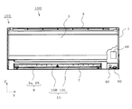
図1〜図3において、空気調和機の室内機100は、上部に吸込口3および下部に吹出口7が形成された本体1と、本体1の前面を開閉自在に覆う前面パネル2と、吸込口3から室内空気を吸い込んで、吹出口7に至る風路6を形成する送風機5と、送風機5の上流側(吸込口3寄り)に設置された熱交換器4とを有している。
そして、本体1の前面で吹出口7の脇に、携帯用情報端末70(図4参照)からの信号を受信する受信装置40と、室内の様子を撮像する室内撮像装置50とが設置されている。
なお、本発明は、受信装置40や室内撮像装置50の型式や設置位置を限定するものではなく、例えば、前面パネル2の中央部等に設置してもよい。さらに、室内機の運転状況を報知するための音声または映像による報知装置(図示しない)が設けられている。
(Indoor unit)
1 to 3, an
A
Note that the present invention does not limit the type or installation position of the
(熱交換器)
熱交換器4は、冷凍サイクルを実行する構成部材の一部であって、前面パネル2に略平行な部分である熱交換前部分4aと、送風機5の前面寄り斜め上方の部分である熱交換上前部分4bと、送風機5の後面寄り斜め上方の部分である熱交換上後部分4cと、を具備している。そして、熱交換前部分4aの下方にはドレンパン8が配置され、ドレンパン8の上面8aが実際にドレンを受けるドレンパン面を形成し、ドレンパン8の下面8bが風路6の前面側を形成している。
(Heat exchanger)
The
(風向調整装置:上下風向板)
風路の吹出口7に近い位置には、風向調整装置である、熱交換器4において調和された室内空気(以下、「調和空気」と称す)の水平方向(左右方向)の吹き出し方向を調整する左側左右風向板群10Lと右側左右風向板群10R(これらをまとめて又はそれぞれを「左右風向板10」と称している)と、風路6の末端である吹出口7には、調和空気の鉛直方向(上下方向)の吹き出し方向を調整する上下風向板9(前上下風向板9aおよび後上下風向板9bをまとめて「上下風向板9」と称している)とが設けられている。
なお、前記「左側」および「右側」とは、室内機100から室内を見たとき、すなわち、本体1の背面側から前面パネル2の方向を見たときに、左手に見えるものを「左側」、右手に見えるものを「右側」と、それぞれ称している。
(Wind direction adjustment device: vertical wind direction plate)
At the position near the
Note that the “left side” and “right side” refer to what is seen on the left hand when viewing the room from the
(風向調整装置:左右風向板)
右側左右風向板群10Rは、左右風向板10a、10b・・・10gによって構成され、ドレンパン8の下面8bに回動自在に設置され、それぞれに右側連結棒20Rが連結されている。また、左側左右風向板群10Lは、左右風向板10h、10i・・・10nによって構成され、それぞれに左側連結棒20Lが連結されている。
そして、右側左右風向板群10Rと右側連結棒20Rとはリンク機構を形成し、また、左側左右風向板群10Lと左側連結棒20Lとはリンク機構を形成し、右側連結棒20Rには右側駆動手段(図示しない)が、左側連結棒20Lには左側駆動手段30Lが、それぞれ連結されている。
したがって、右側連結棒20Rが右側駆動手段によって平行移動された際、左右風向板10a、10b・・・10gは互いに平行を維持しながら回動し、左側連結棒20Lが左側駆動手段30Lによって平行移動された際、左右風向板10h、10i・・・10nは互いに平行を維持しながら回動する。このため、調和空気を吹出口7の全幅に渡って同じ方向に吹き出したり、吹出口7の半幅毎で互いに離れる方向に吹き出したり、吹出口7の半幅毎で互いに衝突する方向に吹き出したりすることが可能になっている。
なお、本発明は、左右風向板10の形態を図示するものに限定するものではなく、左右風向板10の枚数は何れでもよく、また、左右風向板10を3以上の群に分け、それぞれの群を連結棒に回動自在に接合し、それぞれの連結棒を独立に平行移動させるようにしてもよい。
(Wind direction adjusting device: right and left wind direction plate)
The right and left wind
The right and left wind
Therefore, when the right connecting
The present invention is not limited to the shape of the left and right
(上下風向板)
上下風向板9は水平方向(Y方向)に平行な回動中心を有し、本体1に回動自在に設置されている。前上下風向板9aの回動軸および後上下風向板9bの回動軸はそれぞれリンク機構または歯車機構によって連結され、共通の駆動モーターによって回動される。
なお、本発明は、上下風向板9の形態を図示するものに限定するものではなく、前上下風向板9aおよび後上下風向板9bをそれぞれ別個の駆動モーターによって回動してもよい。また、それぞれを左右方向の中央で分割して合計4枚にし、それぞれが別個に独立して回動するようにしてもよい。
(Vertical wind direction plate)
The vertical
In addition, this invention is not limited to what shows the form of the up-and-down
(携帯用情報端末)
図4において、空気調和機の室内機100に送信する携帯用情報端末70は、ユーザーの顔を撮像する顔撮像手段71と、ユーザーが空調環境を設定する空調環境設定手段72と、顔撮像手段71によって撮像されたユーザーの顔に関するユーザー顔情報および空調環境設定手段72によって設定された空調環境に関するユーザー空調情報を室内機100の受信装置40に送信する送信手段73とを具備している。
すなわち、通常、ユーザーは複数であるから、第1ユーザーU1については、第1ユーザーU1の顔F1に関する第1ユーザー顔情報IF1および第1ユーザーU1用に設定された第1ユーザー空調環境C1に関する第1ユーザー空調情報IC1と、第2ユーザーU2については、第2ユーザーU2の顔F2に関する第2ユーザー顔情報IF2および第2ユーザーU2用に設定された第2ユーザー空調環境C2に関する第2ユーザー空調情報IC2等が、受信装置40に送信される。
(Portable information terminal)
In FIG. 4, a portable information terminal 70 that transmits to the
That is, since there are usually a plurality of users, for the first user U1, the first user face information IF1 related to the face F1 of the first user U1 and the first user air conditioning environment C1 set for the first user U1. For the first user air conditioning information IC1 and the second user U2, second user face information IF2 regarding the face F2 of the second user U2 and second user air conditioning information regarding the second user air conditioning environment C2 set for the second user U2 IC2 or the like is transmitted to the receiving
なお、携帯用情報端末70は前記機能を具備するものである限り、その形式は限定されるものではなく、汎用性のある携帯用情報端末70(例えば、タブレット端末、スマートフォン等)であれば、操作開始に先行して、空気調和機の室内機100用の専用アプリケーションを立ち上げることになる。
In addition, as long as the portable information terminal 70 has the above-described function, the format is not limited. If the portable information terminal 70 is a versatile portable information terminal 70 (for example, a tablet terminal, a smartphone, etc.), Prior to the start of operation, a dedicated application for the
図4の(a)において、表示部74に第1ユーザーU1の名称と撮像された第1ユーザーU1の顔(正面)とが表示されている。第1ユーザーU1の名称は、携帯用情報端末70のアプリケーションを立ち上げた直後(起動した直後)に表示部74に表示される指示に基づいて、空調環境設定手段72の操作によって入力され、第1ユーザーU1の顔は、表示部74に表示される指示に基づく空調環境設定手段72の操作によって、顔撮像手段71が撮像したものである。なお、表示部74がタッチパネルである場合は、表示部74の裏面に空調環境設定手段72が配置されているため、外観上は、表示部74が空調環境設定手段72の機能を具備しているとみなすことができる。
In FIG. 4A, the name of the first user U1 and the imaged face (front) of the first user U1 are displayed on the display unit 74. The name of the first user U1 is input by the operation of the air conditioning environment setting means 72 based on an instruction displayed on the display unit 74 immediately after the application of the portable information terminal 70 is started (immediately after starting). The face of one user U1 is captured by the
図4の(b)において、表示部74に第1ユーザーU1用に設定された第1ユーザー空調情報IC1が表示されている。
すなわち、第1ユーザーU1の名称の下方に、「冷房」運転におけるものであることが表示されている。すなわち、「冷房」文字部にタッチすることによって「冷房」の文字が枠付きの太字に変わっている。
そして、第1ユーザーU1の好みの空調環境が、冷房運転の標準的な空調環境に対する変更方向(偏位方向)として、設定温度については「低温側、変更なし、高温側」への変更をそれぞれ示す、「左方向に頂点を持つ三角、四角、右方向に頂点を持つ三角」と、変更後の温度とが表示されている。例えば、低温側への変更を示す「左方向に頂点を持つ三角」を2回タッチしたことによって、標準的な設定温度「28℃」に対して、第1ユーザーU1用には、「26℃」が設定されている。
In FIG. 4B, the first user air conditioning information IC1 set for the first user U1 is displayed on the display unit 74.
That is, below the name of the first user U1, it is displayed that the operation is in the “cooling” operation. That is, by touching the “cooling” character portion, the “cooling” character is changed to bold with a frame.
The preferred air conditioning environment of the first user U1 changes the setting temperature to “low temperature side, no change, high temperature side” as the change direction (deviation direction) with respect to the standard air conditioning environment for cooling operation. “Triangle with apex in the left direction, square, triangle with apex in the right direction” and the temperature after the change are displayed. For example, by touching the “triangle with the apex in the left direction” indicating the change to the low temperature side twice, the standard set temperature “28 ° C.” is changed to “26 ° C.” for the first user U1. "Is set.
また、湿度については、「乾燥側、変更なし、湿り側」を示す三角および四角(温度に準じる)と、前記のようにタッチされた変更後の設定値である湿度「50%」とが表示されている。
また、風速については、「中風」であることが表示されている。すなわち、「中風」の文字部にタッチすることによって、「中風」の文字が枠付きの太字に変わっている。
また、送風モードについては、「集中吹出」であることが表示されている。すなわち、「集中吹出」文字部にタッチすることによって、「集中吹出」の文字が枠付きの太字に変わっている)。
さらに、表示部74には、「登録」の文字が表示され、ユーザーが「登録」の文字にタッチすると、表示されている第1ユーザー空調情報IC1が室内機100に送信され、記憶される。なお、以上は、表示部74(空調環境設定手段72)の一例であって、本発明はかかる表示に限定するものではない。
Regarding the humidity, a triangle and a square (according to temperature) indicating “dry side, no change, wet side” and a humidity “50%” which is the set value after the change touched as described above are displayed. Has been.
The wind speed is displayed as “medium wind”. That is, by touching the character part of “middle wind”, the character of “middle wind” is changed to bold with a frame.
In addition, regarding the air blowing mode, “concentrated blowing” is displayed. That is, by touching the “concentrated balloon” character portion, the “concentrated balloon” character is changed to bold with a frame).
Further, the character “registration” is displayed on the display unit 74. When the user touches the character “registration”, the displayed first user air conditioning information IC1 is transmitted to the
(制御装置)
室内機100には制御装置60が設置されている。制御装置60は携帯用情報端末70から送信されたユーザー顔情報およびユーザー空調情報を記憶し、ユーザー顔情報およびユーザー空調情報と室内撮像装置50が撮像した映像とに基づいて、送風機5、冷凍サイクルおよび風向調整装置(上下風向板9および左右風向板10)の少なくとも1つを制御する(以下、「空調環境制御」と称す)ものである。
制御装置60(正確には、制御装置60に接続された記憶装置(図示しない))には、携帯用情報端末70から送信された、第1ユーザーU1についての第1ユーザー顔情報IF1および第1ユーザー空調情報IC1と、第2ユーザーU2についての第2ユーザー顔情報IF2および第2ユーザー空調情報IC2等が、予め記憶され、ユーザー顔情報データベースおよびユーザー空調情報データベースが形成されている。
そして、空気調和機の室内機100は、第1ユーザーU1(または第2ユーザーU2)等に対して、それぞれの好みに応じた空調環境を実現するものであるため、まず(例えば、入室直後に)、第1ユーザーU1(または第2ユーザーU2)は、自分が「第1ユーザーU1(または第2ユーザーU2)」であることを制御装置60に認識させる必要がある。このために、第1ユーザーU1(または第2ユーザーU2)は、室内機100に近づいて、自分の顔を認識させる。
(Control device)
A
The control device 60 (more precisely, a storage device (not shown) connected to the control device 60) sends the first user face information IF1 and the first user face information IF1 transmitted from the portable information terminal 70 to the first user U1. The user air conditioning information IC1, the second user face information IF2 and the second user air conditioning information IC2 for the second user U2, etc. are stored in advance, and a user face information database and a user air conditioning information database are formed.
And since the
そして、制御装置60は、室内機100に近づいて顔を認識させた人間が、記憶しているユーザー顔情報が示す顔を持つ人間であるのか否か判断し、当該人間が第1ユーザーU1であると判断した場合には、第1ユーザー空調情報IC1に示された第1ユーザー空調環境C1になるように、冷凍サイクルを実行する構成部材、送風機5、左右風向板10あるいは上下風向板9を制御する。
Then, the
(ユーザーの顔の認識)
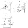
図5は、ユーザーの顔の認識要領を説明するためのものであって、室内機100が、室内90の一方の壁(以下、「背面壁」と称す)91で天井面92に近い位置に設置されている。
また、室内撮像装置50(例えば、30万画素のCCDカメラ)は、斜め下方に向かった視野51を有している。そして、視野51内で、室内撮像装置50から距離L1〜距離L2(>L1)にある範囲(図中、斜線にて示す。「顔認識範囲」と称す)52内に、第1ユーザーU1の顔F1があるとき、制御装置60は顔F1を認識する。
(User face recognition)
FIG. 5 is a diagram for explaining a procedure for recognizing a user's face, and the
The indoor imaging device 50 (for example, a CCD camera with 300,000 pixels) has a field of
さらに、制御装置60は、第1ユーザーU1が室内撮像装置50から距離L3(>L2)よりも近づいたとき、「第1ユーザーU1は、自分が暑がりさんまたは寒がりさんであることを、室内機100に認識させようとしている」と判断し、距離L3よりも近づきながらも、顔認識範囲52内に顔F1がないときには、その旨を図示しない報知手段に報知させる。
例えば、「顔を認識することができません」とか、「もっと近づいて下さい」とか音声によって報知させたり、あるいは、顔を認識することができないことを示すランプを点灯あるいは点滅させたりする。なお、報知手段は、前記音声やランプの点灯あるいは点滅に代えて、文字ないし画像を表示するものであってもよい。
Further, when the first user U1 is closer than the distance L3 (> L2) from the
For example, the user may be notified by voice such as “can't recognize face” or “get closer” or turn on or blink a lamp indicating that the face cannot be recognized. Note that the notification means may display characters or images instead of the sound or lighting or blinking of the lamp.
一方、第1ユーザーU1が室内撮像装置50から距離L3(>L2)よりも近づきながら、所定の時間(例えば、10秒間)が経過するまで、顔F1を認識しないとき(顔F1を顔認識範囲52内に入れないとき)、「第1ユーザーU1は、自分を室内機100に認識させようとしていない」または「第1ユーザーU1は、室内機100を起動する意図がない」と判断する。
このとき、その旨を図示しない報知手段に報知させてもよい。例えば、冷凍サイクルを運転中であれば、「通常モードで運転します」とか音声によって報知したり、あるいは、「通常モードでの運転」を示すランプを点灯あるいは点滅させたりする。
On the other hand, when the face F1 is not recognized until the predetermined time (for example, 10 seconds) elapses while the first user U1 approaches the distance L3 (> L2) from the indoor imaging device 50 (the face F1 is the face recognition range). 52), “the first user U1 is not trying to make the
At this time, a notification means (not shown) may notify the fact. For example, if the refrigeration cycle is in operation, a notification such as “operating in the normal mode” is given by voice, or a lamp indicating “operation in the normal mode” is lit or blinked.
(ユーザーの追跡)
制御装置60は、第1ユーザーU1の顔F1を認識した後は、室内撮像装置50が撮像した第1ユーザーU1の姿から第1ユーザーU1を追跡して、その移動先(以下、「ユーザー位置」と称す)P1を特定する。そして、特定された第1ユーザー位置P1に向けて、第1ユーザー空調情報IC1に示された第1ユーザー空調環境C1になる調和空気を局所的に集中して送風する(集中送風する)。
なお、顔F1を認識した直後は、第1ユーザーU1は室内機100から離れる方向に移動している(移動中である)ため、かかる移動が終わった後、すなわち、第1ユーザーU1が立ち止まった位置、あるいは座った位置を、第1ユーザー位置P1として特定する。
(User tracking)
After recognizing the face F1 of the first user U1, the
Immediately after recognizing the face F1, the first user U1 has moved in a direction away from the indoor unit 100 (being moving), and thus after the movement has ended, that is, the first user U1 has stopped. The position or the sitting position is specified as the first user position P1.
(空調環境制御)
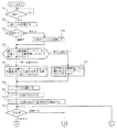
図6および図7に示すフローチャート、および図8および図9に示す平面図に基づいて、制御装置60が実行する空調環境制御について説明する。
図6において、顔認識範囲52に第1ユーザーU1の顔F1があるとき(S1)、制御装置60は顔F1を認識する(S2)。なお、説明の便宜上、第1ユーザーU1の顔F1があるとしているが、第2ユーザーU2の顔F2があるときは、制御装置60は顔F2を認識する。
そして、顔F1が認識されたところで、冷凍サイクルが停止しているときは(S3)、冷凍サイクルを起動する(S4)。
さらに、認識した顔F1と、予めユーザー顔情報データベースに記憶しているユーザー顔情報に示された顔とを対照して、顔F1がユーザー顔情報データベースに記憶しているユーザー顔情報に示された顔に一致するか否か判断する(S5)。
そこで、例えば、顔F1が第1ユーザー顔情報IF1に示された顔であると判断した場合、第1ユーザーU1に向けて第1ユーザー空調環境C1となる調和空気(以下「調和空気」と称す)を吹き出すよう、送風機5、左右風向板10および上下風向板9等を制御する(S6)。
一方、認識した顔F1が、予めユーザー顔情報データベースに記憶しているユーザー顔情報に示された顔と一致しない場合、標準的な空調環境になる調和空気を、当該ユーザーに向けて吹き出すよう、送風機5、左右風向板10および上下風向板9等を制御する(S7)。
(Air conditioning environment control)
The air conditioning environment control executed by the
In FIG. 6, when the face F1 of the first user U1 is in the face recognition range 52 (S1), the
When the face F1 is recognized and the refrigeration cycle is stopped (S3), the refrigeration cycle is started (S4).
Further, the face F1 is shown in the user face information stored in the user face information database by comparing the recognized face F1 with the face shown in the user face information stored in the user face information database in advance. It is determined whether the face matches (S5).
Therefore, for example, when it is determined that the face F1 is the face indicated in the first user face information IF1, conditioned air (hereinafter referred to as “conditioned air”) that becomes the first user air-conditioned environment C1 toward the first user U1. ) Is blown out, the blower 5, the left and right
On the other hand, if the recognized face F1 does not match the face shown in the user face information stored in the user face information database in advance, the conditioned air that becomes a standard air-conditioning environment is blown out toward the user. The blower 5, the left / right
さらに、第1ユーザーU1の移動を追跡し(S8)、第1ユーザーU1が立ち止まった位置または座った第1ユーザー位置P1を特定する(S9)。そして、第1ユーザー位置P1に向けて局所的に集中した第1ユーザー空調環境C1になる調和空気が送られる(集中吹出をする)ように、左右風向板10および上下風向板9の姿勢を制御する(S10)。
したがって、第1ユーザー位置P1に向けた集中吹出が開始されるため、第1ユーザーU1は、予め記憶されている自分好みの第1ユーザー空調環境C1になる調和空気を、集中的に受けることができる。
なお、認識した顔F1が、予めユーザー顔情報データベースに記憶しているユーザー顔情報に示された顔に一致しない場合は、顔F1を有するユーザーが追跡され、該ユーザーに向けて、標準的な空調環境になる調和空気が集中吹出される。
Furthermore, the movement of the first user U1 is tracked (S8), and the position where the first user U1 has stopped or the first user position P1 where the user has sat is specified (S9). And the attitude | position of the left-right
Therefore, since the concentrated blowing toward the first user position P1 is started, the first user U1 can intensively receive the conditioned air that is stored in advance and becomes the first user air-conditioning environment C1 of his / her preference. it can.
If the recognized face F1 does not match the face indicated in the user face information stored in the user face information database in advance, the user having the face F1 is tracked and a standard face is directed toward the user. Concentrated air that becomes an air-conditioned environment is intensively blown out.
図7において、集中吹出を実行中に、第1ユーザーU1またはその他のユーザーが、図示しないリモコンあるいは携帯用情報端末70を操作して集中吹出を停止する釦を押した場合(図6に記載されたS11)、制御装置60は、集中吹出を停止して、分散吹出を開始する(S20)。すなわち、第1ユーザー位置P1に集中して調和空気を吹き出すことなく、分散吹出を開始する。
一方、集中吹出を実行中に、集中吹出を停止する釦が押されなかった場合(S11)、制御装置は、顔F1が認識された第1ユーザーU1の位置の追跡を継続している。
In FIG. 7, when the first user U1 or another user operates a remote controller (not shown) or the portable information terminal 70 and presses a button for stopping the concentrated blowing during the concentrated blowing (described in FIG. 6). S11), the
On the other hand, when the button for stopping the concentrated blowing is not pressed during the concentrated blowing (S11), the control device continues to track the position of the first user U1 where the face F1 is recognized.
そして、第1ユーザーU1が移動することなく所定の時間(例えば、30分間)の間、第1ユーザー位置P1に居たと判定した場合には(S13)、集中吹出を停止して、分散吹出を開始する(S20)。すなわち、第1ユーザーU1は、かかる所定の時間の間に集中吹出によって冷やされ(暖められ)、分散吹出による冷房(暖房)に切り替えても充分快適さを感じることができると推定する。 When it is determined that the first user U1 has been at the first user position P1 for a predetermined time (for example, 30 minutes) without moving (S13), the concentrated blowing is stopped and the distributed blowing is performed. Start (S20). In other words, it is estimated that the first user U1 is cooled (heated) by concentrated blowing during the predetermined time, and can sufficiently feel comfort even when switching to cooling (heating) by distributed blowing.
一方、第1ユーザーU1が所定の時間(例えば、30分間)が経過する前に移動したと判定した場合には(S13)、さらに、第1ユーザーU1が室内90に居るのか室外に出たのか判定する(S14)。
そして、第1ユーザーU1が室内90に居ると判定したとき、第1ユーザーU1の移動先である第1ユーザー位置P3を特定する(S15)。そこで、室内90にその他のユーザーが居ないと判断した場合には(S16)、第1ユーザー位置P1に向けた集中吹出に代えて、移動先の第1ユーザー位置P3に向けた集中吹出を開始する(S17、図9の(a)参照)。
一方、その他のユーザー(例えば、第2ユーザーU2)が室内に居ると判断したときは、集中吹出を停止して、分散吹出を開始する(S20、図9の(b)参照)。すなわち、第2ユーザーU2の快適性を阻害しないようにしている。
On the other hand, if it is determined that the first user U1 has moved before a predetermined time (for example, 30 minutes) has elapsed (S13), whether the first user U1 is in the
And when it determines with the 1st user U1 being in the room |
On the other hand, when it is determined that another user (for example, the second user U2) is in the room, the concentrated blowing is stopped and the distributed blowing is started (S20, see FIG. 9B). That is, the comfort of the second user U2 is not disturbed.
S14において第1ユーザーU1が室内90外に出掛けたと判定した後で、集中吹出を中止する釦が押された場合(S18)、室内90に第1ユーザーU1が居る限り(S12)、集中吹出を中止して、分散吹出を開始する(S20)。一方、第1ユーザーU1が室内90外に出掛けた後、所定の時間(例えば、10分間)が経過すると(S19)、室内90にその他のユーザー(例えば、第2ユーザーU2)が居る限り(S12)、集中吹出を停止して、分散吹出を開始する(S20、図9の(c)参照)。
すなわち、第1ユーザーU1が一旦室内90から出た後は、再度、戻って来るか、戻って来ないかに関わらず、室内90に誰か(例えば、第2ユーザーU2)が居る限り、集中吹出を開始してから所定時間(時間)が経過したところで、分散吹出に切り替わる。
If it is determined in S14 that the first user U1 has gone out of the
That is, once the first user U1 exits the
S12において、室内に誰もいない(ユーザー不在)と判断した場合、冷凍サイクルを停止する(S22)。また、S11において室内にユーザーが居ると判断した場合、集中吹出を停止して、分散吹出を開始する(S12)。
さらに、分散吹出中に、誰か(例えば、第2ユーザーU2)が図示しないリモコンあるいは携帯用情報端末70を操作して分散吹出を停止する釦(冷房または暖房等の停止釦)を押した場合には(S21)、冷凍サイクルの運転を停止する(S22)。
If it is determined in S12 that there is no one in the room (no user), the refrigeration cycle is stopped (S22). If it is determined in S11 that there is a user in the room, the concentrated blowing is stopped and the distributed blowing is started (S12).
Furthermore, when a person (for example, the second user U2) operates a remote controller (not shown) or the portable information terminal 70 and presses a button (stop button for cooling or heating, etc.) to stop the dispersion blowing during the dispersion blowing. (S21), the operation of the refrigeration cycle is stopped (S22).
(集中吹出)
図8の(a)において、第1ユーザー位置P1が室内90の左側(室内機100から見て左手)にある場合、右側左右風向板群10Rおよび左側左右風向板群10Lの両方(図3参照)は、第1ユーザー位置P1に向けて調和空気が吹き出される姿勢(集中吹出の姿勢)にされている。したがって、第1ユーザーU1は、室内90に略均一に調和空気が吹き出される(分散吹出の)場合に比較して、より長時間に渡ってまたはより多量の調和空気を集中的に受けることになる。
すなわち、第1ユーザーU1は、リモコン(図示しない)あるいは携帯用情報端末70を探して、これらに設置された冷房(または暖房)の開始釦を押すという操作が不要であって、顔F1を室内機100に近づけるだけで、冷房(または暖房)運転を開始することができる。しかも、移動して所定の位置に立ち止まるか座っていれば、その位置が第1ユーザー位置P1として自動的に特定され、第1ユーザー位置P1に向けて冷気(または暖気)が送られてくるから、自分の位置に調和空気が確実に届くよう、携帯用情報端末70等を操作する必要がない。
このとき、予め記憶されている第1ユーザーU1好みの第1ユーザー空調環境C1となる調和空気が吹き出されるから、第1ユーザーU1はいちいち、空調環境を設定する手間から開放される。よって、利便性および快適性が向上する。すなわち、ユーザーは、室内機100の前に立って、顔認識されるだけで、自分好みの空調環境を実現することができる。
(Concentrated blowing)
8A, when the first user position P1 is on the left side of the room 90 (left hand as viewed from the indoor unit 100), both the right and left wind
That is, the first user U1 does not need to search for a remote controller (not shown) or the portable information terminal 70 and press a cooling (or heating) start button installed on the remote control (not shown). The cooling (or heating) operation can be started only by bringing it closer to the
At this time, since the conditioned air that becomes the first user air-conditioning environment C1 of the first user U1 preference stored in advance is blown out, the first user U1 is released from the trouble of setting the air-conditioning environment one by one. Therefore, convenience and comfort are improved. That is, the user can realize his / her favorite air-conditioning environment only by standing in front of the
なお、吹き出された調和空気の空気流れは、吹き出し直後は、吹出口の大きさに略同じ断面を有する略均一な流速の束とみなせるものの、室内90を流れる間に周囲の空気と混ざり合ったりしながら広がるため、実際に第1ユーザー位置P1に到達した際の空気流れは、吹出口の大きさに比較して大きな断面を有し、その断面内においても流れの方向や流速が様々な空気流れの束の集合になっている。
このため、本発明における「局所的に集中した」や「集中吹出」とは、広がった空気流れを平均化したときの中央が「特定の位置に向かっていること」を意味し、第1ユーザー位置P1の周囲にも調和空気が到達していることを意味している。
なお、以上は、右側左右風向板群10Rおよび左側左右風向板群10Lの両方が、第1ユーザー位置P1に向けて調和空気を吹き出しているが、本発明は集中吹出の要領をこれに限定するものではない。
The air flow of the conditioned air that has been blown out can be regarded as a bundle of substantially uniform flow speeds having substantially the same cross section as the size of the blowout outlet immediately after being blown out, but may be mixed with the surrounding air while flowing through the
For this reason, “locally concentrated” and “concentrated blowout” in the present invention mean that the center when the air flow spread is averaged is “toward a specific position”, and the first user It means that conditioned air has also reached around the position P1.
In the above, both the right and left wind
例えば、図8の(b)に示すように、左側左右風向板群10Lは常時、第1ユーザー位置P1に向けて調和空気の吹き出す姿勢に固定され、右側左右風向板群10Rは第1ユーザー位置P1および第2ユーザーU2が居る第2ユーザー位置P2を含む所定の範囲(図中、αにて示す)を往復しながら調和空気を吹き出すように回動(スイング)してもよい。
そうすると、第1ユーザーU1に向けては、より多量の第1ユーザー空調環境C1になる調和空気が集中的に吹き出されるから、第1ユーザーU1の快適性が高まると共に、第1ユーザー位置P1を除く範囲には、より少量の第1ユーザー空調環境C1になる調和空気が間欠的に吹き出されることになる。
このため、第1ユーザーU1とは好みの空調環境(体感温度等)が相違する第2ユーザーU2が、第1ユーザー位置P1とは相違する位置である第2ユーザー位置P2に居る場合、第2ユーザー位置P2にはより少量の第1ユーザー空調環境C1になる調和空気が間欠的に吹き出されるから、第2ユーザーU2の快適性も維持されることになる。
For example, as shown in FIG. 8B, the left and right wind
Then, since the conditioned air that becomes a larger amount of the first user air-conditioning environment C1 is intensively blown toward the first user U1, the comfort of the first user U1 is increased and the first user position P1 is set. A smaller amount of the conditioned air that becomes the first user air-conditioning environment C1 is intermittently blown out in the excluded range.
For this reason, when the second user U2 whose preferred air-conditioning environment (sensible temperature, etc.) is different from the first user U1 is in the second user position P2, which is a position different from the first user position P1, the second user U1 Since a smaller amount of the conditioned air that becomes the first user air-conditioning environment C1 is intermittently blown out to the user position P2, the comfort of the second user U2 is also maintained.
さらに、図8の(c)に示すように、右側左右風向板群10Rおよび左側左右風向板群10Lの両方が、第1ユーザー位置P1および第2ユーザー位置P2を含む所定の範囲(図中、αにて示す)を回動(スイング)して調和空気を吹き出すようにし、第1ユーザー位置P1に向かった範囲(図中、βにて示す)においては、これを除く範囲よりもスイング速度を遅く(吹き出し時間を長く)するようにしてもよい。そうすると、図8の(b)に示す場合と同様に、好みの空調環境(体感温度等)がそれぞれ相違する第1ユーザーU1および第2ユーザーU2の快適性も維持されることになる。
なお、集中吹出の要領の選定(図8の(a)、(b)または(c)に示す何れかの選定)は、予め携帯用情報端末70において、決定することができる(例えば、第1ユーザーU1は、集中吹出を好まないから、図8の(b)に示す吹出要領を選択する等)。
Further, as shown in FIG. 8 (c), both the right and left wind
In addition, selection of the point of concentrated blowing (selection shown in (a), (b) or (c) of FIG. 8) can be determined in advance in the portable information terminal 70 (for example, the first Since the user U1 does not like concentrated blowing, he selects the blowing procedure shown in FIG.
[実施の形態2]
図10は、本発明の実施の形態2に係る空気調和機の室内機の空調環境制御における各工程を説明するフローチャートである。なお、実施の形態1と同じ部位または同じステップには同じ符号を付し、一部の説明を省略する。
実施の形態2に係る空気調和機の室内機(以下、「室内機」と称す)200は、風呂上がりや暑い(又は寒い)屋外から室内に入った直後に、一時的に急速に涼しくなりたい(暖まりたい)というユーザーの要請に応えるものである。
[Embodiment 2]
FIG. 10 is a flowchart illustrating each step in the air conditioning environment control of the indoor unit of the air conditioner according to
The indoor unit (hereinafter referred to as “indoor unit”) 200 of the air conditioner according to
すなわち、実施の形態1の室内機100は、顔認識したユーザーの移動を追跡して、移動先であるユーザー位置に向けて集中吹出をするものである(図6におけるS10参照)。そうすると、実施の形態1の室内機100では、第1ユーザーU1は、例えば、湯上がり直後あるいは入室直後に顔認識をすることによって室内機100を起動し、室内機100の至近位置P0(第1ユーザーU1が顔F1を顔認識範囲52に入れることができる位置、および該範囲を含む比較的狭い範囲を指す。図5参照)に立ち続け、所定の時間である至近判断時間(例えば10分)後に、至近位置P0から離れた場合、移動する湯上がりさんに向けて集中吹出が継続されることになる。
このとき、第1ユーザーU1は、集中吹出である第1ユーザー空調環境C1が記憶されている場合であっても、集中吹出を望まないで、分散吹出を希望する場合であるため、実施の形態2の室内機200は、これに対応している。
That is, the
At this time, even if the first user air-conditioning environment C1 that is a concentrated blowout is stored, the first user U1 does not want a concentrated blowout and desires a distributed blowout. The second indoor unit 200 corresponds to this.
図10において、室内機200は、至近位置P0に立っている第1ユーザー位置P1に向けて集中吹出を開始し(S10)、集中吹出を継続しているとき(S10)、ユーザー(例えば、第1ユーザーU1)が、所定の時間である至近判断時間(例えば、30秒間)が経過しても至近位置P0に居続けて(立ち続けて)いるか否かを判断する(S31)。
すなわち、第1ユーザーU1に向けて、涼み終わるまでの所定の時間である至近吹出時間(例えば、10分間)の間は集中吹出が継続されるから、第1ユーザーU1は至近位置P0において涼むことができる(S32)。
そして、前記至近吹出時間(例えば、10分間)が経過した時点で、分散吹出に移行する(図7のS20参照)。
また、前記至近吹出時間(例えば、10分間)が経過する前に、第1ユーザーU1が涼み終わって至近位置P0を離れた場合(S33)には、離れた時点で、分散吹出に移行する(図7のS20参照)。
In FIG. 10, the indoor unit 200 starts concentrated blowing toward the first user position P1 standing at the closest position P0 (S10), and continues the concentrated blowing (S10). It is determined whether one user U1) stays at the close position P0 (continues to stand) even after a close determination time (for example, 30 seconds), which is a predetermined time, has elapsed (S31).
That is, since the concentrated blowing is continued for the first user U1 during the closest blowing time (for example, 10 minutes) that is a predetermined time until the cooling ends, the first user U1 cools at the closest position P0. (S32).
And when the said close blowing time (for example, 10 minutes) passes, it transfers to dispersion | distribution blowing (refer S20 of FIG. 7).
In addition, when the first user U1 finishes cooling and leaves the close position P0 before the close blowing time (for example, 10 minutes) elapses (S33), the process shifts to the distributed blowing at the time of leaving ( (See S20 in FIG. 7).
一方、第1ユーザーU1が、至近位置P0における急速冷房(暖房)を望まない場合、至近位置P0において顔認識をした後、前記至近判断時間(例えば、30秒間)が経過する前に至近位置P0を離れる(S31)。
この場合は、実施の形態1の室内機100と同様に、第1ユーザーU1の移動を追跡し、第1ユーザー位置P1(至近位置P0と相違する)に向けて集中吹出を継続し、再度、所定時間(例えば、30分)が経過したところで、第1ユーザーU1が移動しているか(第1ユーザー位置P1から移動しているか)否かを判断する(図7のS13参照)。
かかる判断をした以降の工程は、実施の形態1の室内機100に同じである(図7に続く)。
On the other hand, when the first user U1 does not want the rapid cooling (heating) at the close position P0, the face is recognized at the close position P0, and then the close position P0 before the close determination time (for example, 30 seconds) elapses. (S31).
In this case, similarly to the
The steps after making such a determination are the same as those of the
以上のように、実施の形態2の室内機200は、前記の各ステップ(工程)を実行するから、第1ユーザーU1は、図示しないリモコンあるいは携帯用情報端末70を操作することなく、至近位置P0に立つだけで、迅速に冷凍サイクルを起動することができ、しかも、至近位置P0に立ち続ける限り、前記至近吹出時間が経過するまでは、第1ユーザー空調環境C1になる調和空気の集中吹出によって急速に涼む(暖まる)ことが可能になる。
また、顔情報が、予めユーザー顔情報データベースに記憶されていないユーザーの場合は、前記至近吹出時間が経過するまでは、標準的な空調環境になる調和空気の集中吹出によって急速に涼む(暖まる)ことが可能になる。
そして、前記至近吹出時間が経過した時点、あるいは、第1ユーザーU1(または、ユーザー顔情報データベースに記憶されていないユーザー)が至近位置P0から離れた時点(涼み終わったとみなすことができる時点に相当する)において、集中吹出を中止し、分散吹出を開始する。
As described above, since the indoor unit 200 according to the second embodiment performs the above steps (processes), the first user U1 can move to the nearest position without operating the remote controller or the portable information terminal 70 (not shown). The refrigeration cycle can be started quickly only by standing at P0. Moreover, as long as the standing position P0 is kept standing, the conditioned air that becomes the first user air-conditioning environment C1 is concentrated until the nearest blowing time elapses. Makes it possible to cool (warm up) rapidly.
Further, in the case of a user whose face information is not stored in the user face information database in advance, the user quickly cools (warms up) by concentrated air blowing of conditioned air that becomes a standard air-conditioning environment until the nearest air blowing time elapses. It becomes possible.
Then, it corresponds to the time when the closest blowing time has elapsed, or the time when the first user U1 (or a user not stored in the user face information database) leaves the closest position P0 (the time when it can be considered that cooling has ended). In this case, the concentrated blowing is stopped and the distributed blowing is started.
したがって、ユーザー(例えば、第1ユーザーU1)は、リモコンあるいは携帯用情報端末70の操作をすることなく、簡便かつ迅速に涼み(暖まり)始めることができ、さらに、涼み(暖まり)終わった後は、リモコンあるいは携帯用情報端末70の操作をすることなく、集中した風流れに晒されないから、快適な空調環境を満喫することができる。 Therefore, the user (for example, the first user U1) can start cooling (warming) easily and quickly without operating the remote control or the portable information terminal 70, and after the cooling (warming) is over. Without being operated by the remote controller or the portable information terminal 70, it is not exposed to the concentrated wind flow, so that a comfortable air-conditioning environment can be enjoyed.
[実施の形態3]
図11は、本発明の実施の形態3に係る空気調和機の室内機の空調環境制御における各工程を説明するフローチャートである。
実施の形態1に係る空気調和機の室内機100は、室内に、至近位置P0において顔認識されたユーザー(例えば、第1ユーザーU1)の他にユーザー(例えば、第2ユーザーU2)が居る場合、第1ユーザーU1用の空調環境である第1ユーザー空調環境C1になる空調空気が分散吹出されるものである(図7のS20)。
このため、例えば、第2ユーザーU2の好む空調環境が第1ユーザー空調環境C1と相違する第2ユーザー空調環境C2であるとき、第2ユーザーU2が不快感を覚える場合がある。
[Embodiment 3]
FIG. 11 is a flowchart illustrating each step in the air conditioning environment control of the indoor unit of the air conditioner according to
When
Therefore, for example, when the air conditioning environment preferred by the second user U2 is the second user air conditioning environment C2 different from the first user air conditioning environment C1, the second user U2 may feel uncomfortable.
図11において、実施の形態3に係る空気調和機の室内機300では、室内に、至近位置P0において顔認識されたユーザー(例えば、第1ユーザーU1)の他にユーザー(例えば、第2ユーザーU2)が居る場合(S16)、当該ユーザー用のユーザー顔情報およびユーザー空調情報が記憶されているかを判断する。すなわち、室内の様子を撮像する室内撮像装置50によって撮像された他のユーザー(例えば、第2ユーザーU2)の顔F2と、ユーザー顔情報データベースに記憶されているユーザー顔情報に示された顔とを対照して、顔F2がユーザー顔情報データベースに記憶されているユーザー顔情報に示された顔に一致するか否か判断する(S41)。
In FIG. 11, in the indoor unit 300 of the air conditioner according to
そこで、例えば、顔F2が第2ユーザー顔情報IF2に示された顔であると判断した場合、第1ユーザーU1用の第1ユーザー空調環境C1と第2ユーザーU2用の第2ユーザー空調環境C2との平均的な空調環境になる空調空気が分散吹出される(S42)。
一方、室内の様子を撮像する室内撮像装置50によって撮像された他のユーザー(例えば、第9ユーザーU9)の顔がユーザー顔情報データベースに記憶しているユーザー顔情報に示された顔に一致しない場合、実施の形態1と同様に、第1ユーザーU1用の第1ユーザー空調環境C1になる空調空気が分散吹出される(S20)。
したがって、例えば、第2ユーザーU2の好む空調環境が第1ユーザー空調環境C1と相違する第2ユーザー空調環境C2であるとき、第2ユーザーU2は、第1ユーザー空調環境C1になる空調空気に晒されることなく、第1ユーザー空調環境C1と第2ユーザー空調環境C2との中間的な空調環境になる調和空気を受けることができるから、不快感が緩和される。
なお、第2ユーザーU2が、第1ユーザー空調環境C1と第2ユーザー空調環境C2との中間的な空調環境になる調和空気でなく、第2ユーザー空調環境C2になる調和空気を望む場合は、第2ユーザーU2自身が室内機100に近づいて、至近位置P0において顔F2を認識させればよい。そうすると、第2ユーザーU2に向けて第2ユーザー空調環境C2になる調和空気が吹き出される。
Therefore, for example, when it is determined that the face F2 is the face indicated in the second user face information IF2, the first user air-conditioning environment C1 for the first user U1 and the second user air-conditioning environment C2 for the second user U2 The air-conditioned air that becomes an average air-conditioning environment is blown out in a distributed manner (S42).
On the other hand, the face of another user (for example, the ninth user U9) imaged by the
Therefore, for example, when the air conditioning environment preferred by the second user U2 is the second user air conditioning environment C2 different from the first user air conditioning environment C1, the second user U2 is exposed to the conditioned air that becomes the first user air conditioning environment C1. Therefore, it is possible to receive conditioned air that is an intermediate air-conditioning environment between the first user air-conditioning environment C1 and the second user air-conditioning environment C2.
In addition, when the 2nd user U2 desires the conditioned air used as the 2nd user air-conditioning environment C2 instead of the conditioned air used as the intermediate air-conditioning environment of the 1st user air-conditioning environment C1 and the 2nd user air-conditioning environment C2, The second user U2 may approach the
1 本体、2 前面パネル、3 吸込口、4 熱交換器、4a 熱交換前部分、4b 熱交換上前部分、4c 熱交換上後部分、5 送風機、6 風路、7 吹出口、8 ドレンパン、8a 上面、8b 下面、9 上下風向板、9a 前上下風向板、9b 後上下風向板、10 左右風向板、10L 左側左右風向板群、10R 右側左右風向板群、10a 左右風向板、10h 左右風向板、20L 左側連結棒、20R 右側連結棒、30L 左側駆動手段、40 受信装置、50 室内撮像装置、51 視野、52 顔認識範囲、60 制御装置、70 携帯用情報端末、71 顔撮像手段、72 空調環境設定手段、73 送信手段、74 表示部、90 室内、91 壁面、92 天井面、100 室内機(実施の形態1)、200 室内機(実施の形態2)、300 室内機(実施の形態3)。 1 Main body, 2 Front panel, 3 Suction port, 4 Heat exchanger, 4a Heat exchange part, 4b Heat exchange front part, 4c Heat exchange upper part, 5 Blower, 6 Air passage, 7 Air outlet, 8 Drain pan, 8a Upper surface, 8b Lower surface, 9 Up / down wind direction plate, 9a Front up / down wind direction plate, 9b Rear up / down wind direction plate, 10 Left / right wind direction plate, 10L Left / right side wind direction plate group, 10R Right / left wind direction plate group, 10a Left / right wind direction plate, 10h Left / right wind direction plate Plate, 20L left connecting rod, 20R right connecting rod, 30L left driving means, 40 receiving device, 50 indoor imaging device, 51 field of view, 52 face recognition range, 60 control device, 70 portable information terminal, 71 face imaging means, 72 Air-conditioning environment setting means, 73 transmission means, 74 display unit, 90 indoors, 91 wall surface, 92 ceiling surface, 100 indoor units (Embodiment 1), 200 indoor units (Embodiment 2) , 300 indoor unit (Embodiment 3).
Claims (13)
前記吸込口から室内空気を吸い込んで、前記吹出口に至る風路を形成する送風機と、
前記風路に設置され、冷凍サイクルの一部を実行する熱交換器と、
前記吹出口に設置され、前記熱交換器において調和空気の吹き出し方向を調整する風向調整装置と、
前記室内を撮像する室内撮像装置と、
携帯用情報端末によって送信されたユーザー顔情報およびユーザー空調情報と前記室内撮像装置が撮像した映像とに基づいて、前記送風機、前記冷凍サイクル及び前記風向調整装置のうち少なくとも1つを制御する制御装置と、を有し、
前記制御装置は、前記室内撮像装置が特定の視野である顔認識範囲に人間の顔があり、当該人間の顔を認識したとき、当該人間の顔と前記携帯用情報端末によって送信され予め記憶しているユーザー顔情報に示された顔とを対照し、当該人間の顔が前記記憶しているユーザー顔情報に示された顔のうちの特定のユーザーの顔であると判断した場合、当該人間に向けて前記特定のユーザー用に設定されたユーザー空調情報に示された空調環境になる調和空気を吹き出すよう、前記送風機、前記冷凍サイクル及び前記風向調整装置のうち少なくとも1つを制御することを特徴とする空気調和機の室内機。 A main body that is formed on the wall surface of the room, each of which has an inlet and an outlet,
A blower that sucks room air from the suction port and forms an air passage leading to the blowout port;
A heat exchanger installed in the air passage and performing a part of the refrigeration cycle;
A wind direction adjusting device that is installed at the outlet and adjusts the blowing direction of conditioned air in the heat exchanger;
An indoor imaging device for imaging the room;
A control device that controls at least one of the blower, the refrigeration cycle, and the wind direction adjusting device based on user face information and user air conditioning information transmitted by the portable information terminal and an image captured by the indoor imaging device And having
When the indoor imaging device has a human face in the face recognition range having a specific field of view and recognizes the human face, the control device transmits the human face and the portable information terminal to store in advance. If the human face is determined to be the face of a specific user among the faces shown in the stored user face information, the human face Controlling at least one of the blower, the refrigeration cycle, and the wind direction adjusting device so as to blow out conditioned air that becomes an air-conditioned environment indicated in the user air-conditioning information set for the specific user. An air conditioner indoor unit.
前記制御装置は、前記顔認識範囲において認識した人間の顔が前記第1ユーザーの顔であると判断した場合、当該人間に向けて前記第1ユーザー空調情報に示された空調環境になる調和空気を、所定の独占時間の間だけ吹き出すよう、前記送風機、前記冷凍サイクルおよび前記風向調整装置のうち少なくとも1つを制御することを特徴とする請求項1乃至3の何れか一項に記載の空気調和機の室内機。 The user face information and the user air conditioning information are first user face information related to the face of the first user, first user air conditioning information set for the first user, second user face information related to the face of the second user, and Second user air conditioning information set for the second user,
When the control device determines that the human face recognized in the face recognition range is the face of the first user, the conditioned air becomes an air-conditioning environment indicated by the first user air-conditioning information toward the human. 4. The air according to claim 1, wherein at least one of the blower, the refrigeration cycle, and the wind direction adjusting device is controlled so as to blow out only during a predetermined monopoly time. The indoor unit of the harmony machine.
前記記憶しているユーザー顔情報およびユーザー空調情報は、ユーザーの顔を撮像する顔撮像手段と、ユーザーが空調環境を設定する空調環境設定手段と、前記顔撮像手段によって撮像されたユーザーの顔に関するユーザー顔情報および前記空調環境設定手段によって設定された空調環境に関するユーザー空調情報を送信する送信手段とを具備する携帯用情報端末によって、送信されたものであって、
前記携帯用情報端末によって撮像されたユーザーの顔に関するユーザー顔情報と、前記携帯用情報端末によって前記ユーザー用に設定された空調環境に関するユーザー空調情報を受信するステップと、
前記制御装置は、前記受信した前記ユーザー顔情報および前記ユーザー空調情報を記憶するステップと、
前記制御装置は、人間の顔が、所定の時間である顔認識時間の間、前記室内撮像装置の視野内の顔認識範囲にあるとき、当該人間の顔を認識するステップと、
該ステップにおいて認識した人間の顔と前記ユーザー顔情報に示された顔とを対照して、当該人間の顔が前記記憶しているユーザー顔情報に示された顔のうちの特定のユーザーの顔であると判断した場合、前記冷凍サイクルが停止しているときは、前記冷凍サイクルを起動し、該起動した後または前記冷凍サイクルが運転されているときは、当該人間に向けて前記特定のユーザー用に設定されたユーザー空調情報に示された空調環境になる調和空気を吹き出すよう、前記送風機、前記冷凍サイクルおよび前記風向調整装置のうち少なくとも1つを制御するステップと、
前記顔認識範囲において人間の顔が認識された人間が、前記調和空気を吹き出した後、所定の時間である至近判断時間になる前に、前記顔認識範囲を含む比較的狭い範囲である至近位置の外に移動した場合、あるいは、前記調和空気を吹き出した後、所定の時間である至近吹出時間が経過した場合、あるいは、前記至近吹出時間になる前に、前記人間の顔が認識された人間が前記至近位置の外に移動した場合、の何れかの場合に前記冷凍サイクルを停止する吹出停止ステップと、
を実行することを特徴とする空気調和機の室内機。 A suction port and an air outlet are respectively formed, a main body installed on a wall surface in the room, an air blower that draws indoor air from the air inlet and forms an air passage leading to the air outlet, and is installed in the air passage. A heat exchanger that executes a part of the refrigeration cycle; a wind direction adjusting device that is installed at the outlet and adjusts the direction in which conditioned air is blown in the heat exchanger; an indoor imaging device that images the room; A control device that controls at least one of the blower, the refrigeration cycle, and the airflow direction adjustment device based on the user face information and the user air conditioning information and the image captured by the indoor imaging device,
The stored user face information and user air conditioning information relate to a face imaging unit that images a user's face, an air conditioning environment setting unit that allows a user to set an air conditioning environment, and a user's face imaged by the face imaging unit. Transmitted by a portable information terminal comprising user face information and transmission means for transmitting user air conditioning information relating to the air conditioning environment set by the air conditioning environment setting means,
Receiving user face information relating to a user's face imaged by the portable information terminal, and user air conditioning information relating to an air conditioning environment set for the user by the portable information terminal;
The control device stores the received user face information and the user air conditioning information;
The control device recognizes a human face when the human face is in a face recognition range within a field of view of the indoor imaging device for a face recognition time that is a predetermined time; and
The human face recognized in the step is compared with the face shown in the user face information, and the face of the specific user among the faces shown in the stored user face information is stored in the human face. When the refrigeration cycle is stopped, the refrigeration cycle is activated, and after the activation or when the refrigeration cycle is operated, the specific user is directed toward the person. Controlling at least one of the blower, the refrigeration cycle, and the wind direction adjusting device so as to blow out conditioned air that becomes an air conditioning environment indicated in the user air conditioning information set for
A close position that is a relatively narrow range including the face recognition range after a human whose face has been recognized in the face recognition range has blown out the conditioned air and before a close determination time that is a predetermined time. A person who has recognized the human face before the closest blowing time, or when the closest blowing time, which is a predetermined time, has passed after blowing out the conditioned air Is moved out of the close position, blowout stop step to stop the refrigeration cycle in any case,
An air conditioner indoor unit characterized in that
前記制御装置は、前記顔認識範囲にある人間の顔と前記ユーザー顔情報に示された顔とを対照して、当該人間の顔が前記第1ユーザーの顔であると判断した場合、前記冷凍サイクルが停止しているときは、前記冷凍サイクルを起動し、該起動した後または前記冷凍サイクルが運転されているときは、当該人間に向けて前記第1ユーザー空調情報に示された空調環境になる調和空気を吹き出すよう、所定の独占時間が経過するまでの間、前記送風機、前記冷凍サイクルおよび前記風向調整装置のうち少なくとも1つを制御するステップと、
前記所定の独占時間が経過した後に、前記室内に、前記顔認識範囲において顔が認識された人間と、前記顔認識範囲において顔が認識された人間以外の人間とがいると判断し、前記顔認識範囲において顔を認識した人間以外の人間の顔が前記第2ユーザーの顔であると判断した場合、前記室内に向けて前記第1ユーザー空調情報に示された空調環境と前記第2ユーザー空調情報に示された空調環境との平均的な空調境になる調和空気を吹き出すよう、前記送風機、前記冷凍サイクルおよび前記風向調整装置のうち少なくとも1つを制御するステップと、を有することを特徴とする請求項9記載の空気調和機の室内機。 The user face information and the user air conditioning information are first user face information related to the face of the first user, first user air conditioning information set for the first user, second user face information related to the face of the second user, and Second user air conditioning information set for the second user,
The control device compares the human face in the face recognition range with the face indicated in the user face information, and determines that the human face is the face of the first user. When the cycle is stopped, the refrigeration cycle is activated, and after the activation or when the refrigeration cycle is operated, the air conditioning environment indicated in the first user air conditioning information is directed toward the person. Controlling at least one of the blower, the refrigeration cycle, and the wind direction adjusting device until a predetermined monopoly time elapses to blow out conditioned air
After the predetermined exclusive time has elapsed, it is determined that there are a person whose face is recognized in the face recognition range and a person other than a person whose face is recognized in the face recognition range in the room, When it is determined that a human face other than a human who has recognized a face in the recognition range is the face of the second user, the air conditioning environment indicated in the first user air conditioning information and the second user air conditioning toward the room And controlling at least one of the blower, the refrigeration cycle, and the wind direction adjusting device so as to blow out conditioned air that becomes an average air-conditioning boundary with the air-conditioning environment indicated in the information, The indoor unit of the air conditioner according to claim 9.
ユーザーの顔を撮像する顔撮像手段と、
ユーザーが空調環境を設定する空調環境設定手段と、
前記顔撮像手段によって撮像されたユーザーの顔に関するユーザー顔情報及び前記空調環境設定手段によって撮像された空調環境に関するユーザー空調情報を送信する送信手段と、を具備していることを特徴とする請求項1乃至12の何れか一項に記載の空気調和装置の室内機。 The portable information terminal is
A face imaging means for imaging a user's face;
An air conditioning environment setting means for the user to set the air conditioning environment;
The apparatus includes: transmission means for transmitting user face information relating to a user's face imaged by the face imaging means and user air conditioning information relating to the air conditioning environment imaged by the air conditioning environment setting means. The indoor unit of the air conditioning apparatus as described in any one of 1 thru | or 12.
Priority Applications (5)
| Application Number | Priority Date | Filing Date | Title |
|---|---|---|---|
| JP2012159540A JP2014020670A (en) | 2012-07-18 | 2012-07-18 | Indoor unit for air conditioner |
| US13/851,167 US9551541B2 (en) | 2012-07-18 | 2013-03-27 | Indoor unit of air-conditioning apparatus |
| KR20130042824A KR101492711B1 (en) | 2012-07-18 | 2013-04-18 | Indoor unit of air conditioning apparatus |
| EP13166735.4A EP2687789B1 (en) | 2012-07-18 | 2013-05-07 | Indoor unit of air-conditioning apparatus |
| CN201310192773.XA CN103574854B (en) | 2012-07-18 | 2013-05-23 | The indoor set of air regulator |
Applications Claiming Priority (1)
| Application Number | Priority Date | Filing Date | Title |
|---|---|---|---|
| JP2012159540A JP2014020670A (en) | 2012-07-18 | 2012-07-18 | Indoor unit for air conditioner |
Publications (2)
| Publication Number | Publication Date |
|---|---|
| JP2014020670A true JP2014020670A (en) | 2014-02-03 |
| JP2014020670A5 JP2014020670A5 (en) | 2014-09-04 |
Family
ID=48325448
Family Applications (1)
| Application Number | Title | Priority Date | Filing Date |
|---|---|---|---|
| JP2012159540A Pending JP2014020670A (en) | 2012-07-18 | 2012-07-18 | Indoor unit for air conditioner |
Country Status (5)
| Country | Link |
|---|---|
| US (1) | US9551541B2 (en) |
| EP (1) | EP2687789B1 (en) |
| JP (1) | JP2014020670A (en) |
| KR (1) | KR101492711B1 (en) |
| CN (1) | CN103574854B (en) |
Cited By (9)
| Publication number | Priority date | Publication date | Assignee | Title |
|---|---|---|---|---|
| CN106016580A (en) * | 2016-05-09 | 2016-10-12 | 珠海格力电器股份有限公司 | Air speed adjusting method and device for indoor fan |
| WO2016189867A1 (en) * | 2015-05-27 | 2016-12-01 | パナソニックIpマネジメント株式会社 | Air blower |
| CN106642517A (en) * | 2016-09-12 | 2017-05-10 | 珠海格力电器股份有限公司 | Temperature adjusting method and device of air conditioner and air conditioner |
| CN107131608A (en) * | 2017-05-05 | 2017-09-05 | 珠海格力电器股份有限公司 | Air conditioning control method and equipment |
| JP2017198421A (en) * | 2016-04-28 | 2017-11-02 | シャープ株式会社 | Air conditioner and remote control device |
| JP2019527575A (en) * | 2016-07-15 | 2019-10-03 | コーニンクレッカ フィリップス エヌ ヴェKoninklijke Philips N.V. | Targeted clean air supply |
| JP2020085302A (en) * | 2018-11-21 | 2020-06-04 | 三菱電機株式会社 | Air conditioner, air conditioning system, wind direction control method, and program |
| JP2021032485A (en) * | 2019-08-26 | 2021-03-01 | ダイキン工業株式会社 | Air conditioning system, and information processing method using air conditioning system |
| CN112432315A (en) * | 2020-10-28 | 2021-03-02 | 青岛海尔空调器有限总公司 | Air conditioner and control method thereof |
Families Citing this family (30)
| Publication number | Priority date | Publication date | Assignee | Title |
|---|---|---|---|---|
| US8864447B1 (en) * | 2010-07-01 | 2014-10-21 | Sharon K. Humphrey | Low-profile, ceiling-mounted fan |
| JP6395087B2 (en) * | 2014-01-14 | 2018-09-26 | パナソニックIpマネジメント株式会社 | Environmental control system, control device, program |
| CN104896652A (en) * | 2014-03-06 | 2015-09-09 | 李文嵩 | Intelligent air conditioning system |
| US9612029B2 (en) * | 2014-12-04 | 2017-04-04 | Shek Fat Bosco Ng | Airflow systems |
| US10739033B2 (en) * | 2015-08-06 | 2020-08-11 | Mitsubishi Electric Corporation | Air-conditioning apparatus |
| CN105042789B (en) * | 2015-08-12 | 2018-03-16 | 深圳创维-Rgb电子有限公司 | The control method and system of a kind of intelligent air condition |
| WO2017028176A1 (en) * | 2015-08-17 | 2017-02-23 | 罗旭宜 | Method and air conditioner for indicating information when matching air conditioner state with facial feature |
| WO2017028253A1 (en) * | 2015-08-18 | 2017-02-23 | 罗旭宜 | Method and air conditioner for recording air conditioner state according to facial feature |
| WO2017028190A1 (en) * | 2015-08-18 | 2017-02-23 | 黄冠明 | Method for pushing information when fan state is matched according to facial feature, and fan |
| WO2017028188A1 (en) * | 2015-08-18 | 2017-02-23 | 黄冠明 | Method for prompting patent information when fan is adjusted according to iris, and fan |
| JP6213539B2 (en) * | 2015-09-29 | 2017-10-18 | ダイキン工業株式会社 | Indoor unit of air conditioner |
| CN105911905A (en) * | 2016-04-11 | 2016-08-31 | 联想(北京)有限公司 | Control method and electronic device |
| CN106225144A (en) * | 2016-07-21 | 2016-12-14 | 广东美的制冷设备有限公司 | Air-conditioner and control method thereof |
| CN106373312A (en) * | 2016-08-27 | 2017-02-01 | 桂林信通科技有限公司 | Safety protection method and system based on air-conditioner |
| CN106837842B (en) * | 2017-02-28 | 2018-09-04 | 京东方科技集团股份有限公司 | A kind of method of intelligent fan and control intelligent fan |
| US11185235B2 (en) * | 2017-03-27 | 2021-11-30 | Panasonic Intellectual Property Management Co., Ltd. | Information processing method, information processing device, and recording medium |
| EP3608599B1 (en) * | 2017-04-07 | 2023-12-06 | Mitsubishi Electric Corporation | Air conditioner |
| KR102056390B1 (en) * | 2017-07-18 | 2019-12-16 | 송명은 | Electric fan or heater capable of controlling rotation range |
| CN107576032A (en) * | 2017-09-25 | 2018-01-12 | 南京律智诚专利技术开发有限公司 | A kind of recognition of face room conditioning regulator control system and its air-conditioning |
| WO2019097567A1 (en) * | 2017-11-14 | 2019-05-23 | 三菱電機株式会社 | Control system, installation equipment, remote controller, control method, and program |
| BE1026288B1 (en) * | 2018-05-16 | 2019-12-17 | Niko Nv | ADAPTIVE HVAC CONTROL SYSTEM |
| CN110793147A (en) * | 2018-08-03 | 2020-02-14 | 珠海格力电器股份有限公司 | Air conditioner control method and device |
| CN109654650A (en) * | 2018-12-18 | 2019-04-19 | 江苏瀚远科技股份有限公司 | The method and apparatus for controlling central air-conditioning |
| CN110220284A (en) * | 2019-05-22 | 2019-09-10 | 青岛海尔空调器有限总公司 | Air conditioner and its control method |
| CN110195923A (en) * | 2019-06-03 | 2019-09-03 | 宁波奥克斯电气股份有限公司 | A kind of air-conditioning control method, air conditioner and storage medium |
| US11927931B2 (en) | 2019-06-27 | 2024-03-12 | Lg Electronics Inc. | Artificial intelligence-based air conditioner |
| CN110906513A (en) * | 2019-11-27 | 2020-03-24 | 广东美的制冷设备有限公司 | Air conditioner robot control method and device based on image recognition |
| US20220282736A1 (en) * | 2021-03-08 | 2022-09-08 | Macroair Technologies, Inc. | System and kit for attachment to a support structure of a control panel for a high-volume low speed fan |
| US20230391158A1 (en) * | 2022-06-03 | 2023-12-07 | Paris Smith | Dynamically Controlled Cooling Device |
| CN114838404B (en) * | 2022-06-10 | 2023-08-29 | 海信空调有限公司 | Air conditioner and comfort control method thereof |
Citations (10)
| Publication number | Priority date | Publication date | Assignee | Title |
|---|---|---|---|---|
| JPH01147244A (en) * | 1987-12-02 | 1989-06-08 | Sharp Corp | Airconditioner |
| JPH10232044A (en) * | 1997-02-19 | 1998-09-02 | Sharp Corp | Operation control system for air-conditioner |
| JP2003042521A (en) * | 2001-07-26 | 2003-02-13 | Hitachi Ltd | Air conditioning apparatus |
| JP2005106355A (en) * | 2003-09-30 | 2005-04-21 | Fujitsu General Ltd | Control method for air conditioner |
| JP2006220405A (en) * | 2005-01-12 | 2006-08-24 | Mitsubishi Electric Corp | Air conditioner |
| JP2009139010A (en) * | 2007-12-06 | 2009-06-25 | Sharp Corp | Air conditioner |
| JP2010025359A (en) * | 2008-07-15 | 2010-02-04 | Fujitsu General Ltd | Air conditioner |
| JP2010107114A (en) * | 2008-10-30 | 2010-05-13 | Mitsubishi Electric Corp | Imaging device and air conditioner |
| JP2010266188A (en) * | 2009-04-15 | 2010-11-25 | Panasonic Corp | Air conditioning system |
| JP2011169536A (en) * | 2010-02-19 | 2011-09-01 | Toshiba Carrier Corp | Electrical apparatus and air conditioner |
Family Cites Families (15)
| Publication number | Priority date | Publication date | Assignee | Title |
|---|---|---|---|---|
| JPH0535877A (en) | 1991-08-01 | 1993-02-12 | Sharp Corp | Comfortable environment offering device |
| US5180333A (en) * | 1991-10-28 | 1993-01-19 | Norm Pacific Automation Corp. | Ventilation device adjusted and controlled automatically with movement of human body |
| JP2957378B2 (en) | 1993-05-18 | 1999-10-04 | シャープ株式会社 | Air conditioner |
| JPH07271482A (en) | 1994-03-31 | 1995-10-20 | Sharp Corp | Computer system |
| US20080065291A1 (en) * | 2002-11-04 | 2008-03-13 | Automotive Technologies International, Inc. | Gesture-Based Control of Vehicular Components |
| US7084774B2 (en) * | 2003-11-13 | 2006-08-01 | International Business Machines Corporation | Temperature control system |
| JP2005172288A (en) | 2003-12-09 | 2005-06-30 | Mitsubishi Heavy Ind Ltd | Controlling system for air conditioner |
| US20110039490A1 (en) * | 2009-08-12 | 2011-02-17 | James Wiese | Window Fan |
| US8601573B2 (en) * | 2009-09-17 | 2013-12-03 | International Business Machines Corporation | Facial recognition for document and application data access control |
| CN101673094A (en) * | 2009-09-23 | 2010-03-17 | 曾昭兴 | Control device of home appliance and control method thereof |
| US8864447B1 (en) * | 2010-07-01 | 2014-10-21 | Sharon K. Humphrey | Low-profile, ceiling-mounted fan |
| KR101800887B1 (en) | 2010-12-16 | 2017-11-23 | 엘지전자 주식회사 | Network system |
| US20120158203A1 (en) * | 2010-12-17 | 2012-06-21 | Crestron Electronics, Inc. | Personal Energy Management System |
| KR20120079245A (en) * | 2011-01-04 | 2012-07-12 | 엘지전자 주식회사 | Control method for air conditioning apparatus |
| US20130204408A1 (en) * | 2012-02-06 | 2013-08-08 | Honeywell International Inc. | System for controlling home automation system using body movements |
-
2012
- 2012-07-18 JP JP2012159540A patent/JP2014020670A/en active Pending
-
2013
- 2013-03-27 US US13/851,167 patent/US9551541B2/en active Active
- 2013-04-18 KR KR20130042824A patent/KR101492711B1/en active IP Right Grant
- 2013-05-07 EP EP13166735.4A patent/EP2687789B1/en not_active Not-in-force
- 2013-05-23 CN CN201310192773.XA patent/CN103574854B/en active Active
Patent Citations (10)
| Publication number | Priority date | Publication date | Assignee | Title |
|---|---|---|---|---|
| JPH01147244A (en) * | 1987-12-02 | 1989-06-08 | Sharp Corp | Airconditioner |
| JPH10232044A (en) * | 1997-02-19 | 1998-09-02 | Sharp Corp | Operation control system for air-conditioner |
| JP2003042521A (en) * | 2001-07-26 | 2003-02-13 | Hitachi Ltd | Air conditioning apparatus |
| JP2005106355A (en) * | 2003-09-30 | 2005-04-21 | Fujitsu General Ltd | Control method for air conditioner |
| JP2006220405A (en) * | 2005-01-12 | 2006-08-24 | Mitsubishi Electric Corp | Air conditioner |
| JP2009139010A (en) * | 2007-12-06 | 2009-06-25 | Sharp Corp | Air conditioner |
| JP2010025359A (en) * | 2008-07-15 | 2010-02-04 | Fujitsu General Ltd | Air conditioner |
| JP2010107114A (en) * | 2008-10-30 | 2010-05-13 | Mitsubishi Electric Corp | Imaging device and air conditioner |
| JP2010266188A (en) * | 2009-04-15 | 2010-11-25 | Panasonic Corp | Air conditioning system |
| JP2011169536A (en) * | 2010-02-19 | 2011-09-01 | Toshiba Carrier Corp | Electrical apparatus and air conditioner |
Cited By (14)
| Publication number | Priority date | Publication date | Assignee | Title |
|---|---|---|---|---|
| WO2016189867A1 (en) * | 2015-05-27 | 2016-12-01 | パナソニックIpマネジメント株式会社 | Air blower |
| JPWO2016189867A1 (en) * | 2015-05-27 | 2018-03-15 | パナソニックIpマネジメント株式会社 | Blower |
| JP2017198421A (en) * | 2016-04-28 | 2017-11-02 | シャープ株式会社 | Air conditioner and remote control device |
| CN106016580A (en) * | 2016-05-09 | 2016-10-12 | 珠海格力电器股份有限公司 | Air speed adjusting method and device for indoor fan |
| CN106016580B (en) * | 2016-05-09 | 2019-01-18 | 珠海格力电器股份有限公司 | The wind speed adjusting method and device of indoor fan |
| JP2019527575A (en) * | 2016-07-15 | 2019-10-03 | コーニンクレッカ フィリップス エヌ ヴェKoninklijke Philips N.V. | Targeted clean air supply |
| CN106642517A (en) * | 2016-09-12 | 2017-05-10 | 珠海格力电器股份有限公司 | Temperature adjusting method and device of air conditioner and air conditioner |
| CN107131608A (en) * | 2017-05-05 | 2017-09-05 | 珠海格力电器股份有限公司 | Air conditioning control method and equipment |
| JP2020085302A (en) * | 2018-11-21 | 2020-06-04 | 三菱電機株式会社 | Air conditioner, air conditioning system, wind direction control method, and program |
| JP7199207B2 (en) | 2018-11-21 | 2023-01-05 | 三菱電機株式会社 | Air conditioner, air conditioning system, wind direction control method, and program |
| JP2021032485A (en) * | 2019-08-26 | 2021-03-01 | ダイキン工業株式会社 | Air conditioning system, and information processing method using air conditioning system |
| WO2021039636A1 (en) * | 2019-08-26 | 2021-03-04 | ダイキン工業株式会社 | Air conditioning system and method for providing information using air conditioning system |
| CN112432315A (en) * | 2020-10-28 | 2021-03-02 | 青岛海尔空调器有限总公司 | Air conditioner and control method thereof |
| CN112432315B (en) * | 2020-10-28 | 2021-10-29 | 青岛海尔空调器有限总公司 | Air conditioner and control method thereof |
Also Published As
| Publication number | Publication date |
|---|---|
| US20140020860A1 (en) | 2014-01-23 |
| KR20140011248A (en) | 2014-01-28 |
| EP2687789B1 (en) | 2019-03-13 |
| KR101492711B1 (en) | 2015-02-11 |
| CN103574854A (en) | 2014-02-12 |
| EP2687789A1 (en) | 2014-01-22 |
| CN103574854B (en) | 2016-02-10 |
| US9551541B2 (en) | 2017-01-24 |
Similar Documents
| Publication | Publication Date | Title |
|---|---|---|
| JP2014020670A (en) | Indoor unit for air conditioner | |
| JP5409825B2 (en) | Air conditioner indoor unit | |
| JP5858850B2 (en) | Air conditioner indoor unit | |
| JP6104131B2 (en) | Air conditioner indoor unit | |
| JP6104151B2 (en) | Air conditioner indoor unit | |
| JP6249647B2 (en) | Air conditioner indoor unit | |
| JP5863593B2 (en) | Air conditioner indoor unit | |
| JP6128925B2 (en) | Air conditioner indoor unit | |
| JP5988913B2 (en) | Air conditioner indoor unit | |
| JP6000217B2 (en) | Air conditioner indoor unit | |
| JP5984453B2 (en) | Air conditioner indoor unit | |
| WO2018029797A1 (en) | Air conditioner | |
| JP5506980B2 (en) | Air conditioner indoor unit | |
| JP6178992B2 (en) | Air conditioner | |
| JP2020098061A (en) | Air conditioner and display control method | |
| JP2013238396A (en) | Indoor unit of air-conditioning apparatus |
Legal Events
| Date | Code | Title | Description |
|---|---|---|---|
| A521 | Request for written amendment filed |
Free format text: JAPANESE INTERMEDIATE CODE: A523 Effective date: 20140718 |
|
| A621 | Written request for application examination |
Free format text: JAPANESE INTERMEDIATE CODE: A621 Effective date: 20140718 |
|
| A977 | Report on retrieval |
Free format text: JAPANESE INTERMEDIATE CODE: A971007 Effective date: 20141121 |
|
| A131 | Notification of reasons for refusal |
Free format text: JAPANESE INTERMEDIATE CODE: A131 Effective date: 20141209 |
|
| A521 | Request for written amendment filed |
Free format text: JAPANESE INTERMEDIATE CODE: A523 Effective date: 20150205 |
|
| A02 | Decision of refusal |
Free format text: JAPANESE INTERMEDIATE CODE: A02 Effective date: 20150707 |