JP2011117627A - Air conditioner - Google Patents
Air conditioner Download PDFInfo
- Publication number
- JP2011117627A JP2011117627A JP2009273472A JP2009273472A JP2011117627A JP 2011117627 A JP2011117627 A JP 2011117627A JP 2009273472 A JP2009273472 A JP 2009273472A JP 2009273472 A JP2009273472 A JP 2009273472A JP 2011117627 A JP2011117627 A JP 2011117627A
- Authority
- JP
- Japan
- Prior art keywords
- button
- temperature
- air conditioner
- remote control
- displayed
- Prior art date
- Legal status (The legal status is an assumption and is not a legal conclusion. Google has not performed a legal analysis and makes no representation as to the accuracy of the status listed.)
- Pending
Links
Images


Landscapes
- Air Conditioning Control Device (AREA)
Abstract
Description
この発明は、空気調和機に関する。詳しくは、省エネアドバイスの内容を、遠隔制御装置のインターフェイス部に一括表示する空気調和機に関する。 The present invention relates to an air conditioner. Specifically, the present invention relates to an air conditioner that collectively displays the content of energy-saving advice on the interface unit of the remote control device.
空気調和機の高機能化ならびに高付加価値デバイスの搭載に伴い、高付加価値機能を実行/停止するための信号を発信するリモコン(遠隔制御装置)のボタン数は増加の一途である。 As air conditioners become more sophisticated and high value-added devices are installed, the number of buttons on a remote control (remote control device) that transmits a signal for executing / stopping the high value-added function is increasing.
リモコンの限られたスペース内におけるボタン数の増加に対応するために、以下に示す方法などを用いてリモコンとユーザーとのインターフェイス操作部を構成している。
(1)ボタン自身の大きさを縮小する方法;
(2)配列するボタン列間のスペースを縮小する方法;
(3)一つのボタンにて多数の機能を選択させるインターフェイスを採用する方法。
In order to cope with an increase in the number of buttons in a limited space of the remote controller, an interface operation unit between the remote controller and the user is configured using the following method.
(1) A method of reducing the size of the button itself;
(2) A method for reducing the space between arranged button rows;
(3) A method of adopting an interface for selecting a large number of functions with one button.
その為、ボタン一つ一つの機能を表現する言葉自体もボタンの大きさ、ボタン間スペースの広さに依存することになる。そのため、ユーザーが快適な空調を実現するために必要となる空気調和機の機能選択の操作自体を難しくしてしまう。それと同時に、ボタン上またはボタン近傍に記載された機能言葉だけでは、ユーザーがボタンを押した際に実現される機能を理解できず、操作すること自体をあきらめてしまうという課題があった。 For this reason, the word that expresses the function of each button depends on the size of the button and the space between the buttons. Therefore, the operation itself of the function selection of the air conditioner necessary for the user to realize comfortable air conditioning becomes difficult. At the same time, only the function words described on or near the button cannot understand the function realized when the user presses the button, and there is a problem that the operation itself is given up.
そこで、ユーザーの操作負担を軽減させることができる空気調和機のリモコンが提案されている(例えば、特許文献1参照)。 Then, the remote control of the air conditioner which can reduce a user's operation burden is proposed (for example, refer patent document 1).
しかしながら、上記特許文献1に記載された空気調和機のリモコンは、フルドットの液晶ディスプレイで構成されるインターフェイス表示部を備えていないか、もしくはフルドットの液晶ディスプレイで構成されるインターフェイス表示部を備えていても、決められた領域にて決められた内容でしか表示することができないセグメント表示のメインの表示部に比べて画面サイズが小さく、例えば、空気調和機の省エネアドバイスの詳細内容を、一括して同時に表示することができないという課題がある。
However, the air conditioner remote control described in
この発明は、上記のような課題を解決するためになされたもので、省エネアドバイスの内容を、遠隔制御装置のインターフェイス部に一括表示することができる空気調和機を提供する。 The present invention has been made to solve the above-described problems, and provides an air conditioner capable of collectively displaying the contents of energy-saving advice on an interface unit of a remote control device.
この発明に係る空気調和機は、部屋の空気を吸い込む吸込口と調和空気を吹き出す吹出口とを有する略箱状の本体と、
本体の前面に所定の俯角で下向きに取り付けられ、温度検出対象範囲を左右に走査して温度検出対象の温度を検出する赤外線センサと、
赤外線センサにより人や発熱機器の存在を検知して、当該空気調和機の運転を制御する制御部と、
遠隔制御装置本体と、遠隔制御装置本体に設けられ、フルドットの液晶ディスプレイで構成されるインターフェイス表示部と、遠隔制御装置本体に設けられる情報要求ボタンと、を有し、ユーザーが当該空気調和機の運転を制御する遠隔制御装置と、
制御部と遠隔制御装置との間で双方向通信を行う通信部と、を備え、
ユーザーが情報要求ボタンを押すことにより、制御部が有する省エネアドバイスの内容が、通信部を介してインターフェイス表示部に一括表示されるものである。
An air conditioner according to the present invention has a substantially box-shaped main body having a suction port for sucking room air and a blow-out port for blowing out conditioned air,
An infrared sensor that is mounted downward on the front surface of the main body at a predetermined depression angle, scans the temperature detection target range left and right, and detects the temperature of the temperature detection target;
A control unit that detects the presence of a person or a heat generating device with an infrared sensor and controls the operation of the air conditioner;
The remote control device main body, an interface display unit provided on the remote control device main body and configured by a full-dot liquid crystal display, and an information request button provided on the remote control device main body, the user is concerned with the air conditioner A remote control device for controlling the operation of
A communication unit that performs bidirectional communication between the control unit and the remote control device,
When the user presses the information request button, the contents of the energy saving advice possessed by the control unit are collectively displayed on the interface display unit via the communication unit.
この発明に係る空気調和機は、遠隔制御装置がフルドットの液晶ディスプレイで構成されるインターフェイス表示部を備えるので、省エネアドバイスの内容をインターフェイス部に一括表示することができる。 In the air conditioner according to the present invention, since the remote control device includes the interface display unit configured by a full-dot liquid crystal display, the contents of the energy saving advice can be collectively displayed on the interface unit.
実施の形態1.
先ず、本実施の形態の概要を説明する。空気調和機(室内機)は、温度検出対象範囲を走査しながら温度を検出する赤外線センサを備え、赤外線センサにより熱源検知を行って人や発熱機器の存在を検知して、快適な制御を行うようにしている。
First, an outline of the present embodiment will be described. An air conditioner (indoor unit) includes an infrared sensor that detects a temperature while scanning a temperature detection target range, performs heat source detection by the infrared sensor, detects the presence of a person or a heat generating device, and performs comfortable control. I am doing so.
通常、室内機は部屋の高所の壁に据付られるが、室内機が据付られる壁における左右の位置は、様々である。壁の左右方向の略中央に据付られる場合もあるし、室内機から見て右側又は左側の壁に接近して据付られる場合もある。以下、この明細書では、部屋の左右方向とは、「室内機(赤外線センサ3)から見た左右方向」、と定義する。 Usually, an indoor unit is installed on a wall at a high place in a room, but the left and right positions on the wall on which the indoor unit is installed are various. It may be installed at the approximate center in the left-right direction of the wall, or may be installed close to the right or left wall as viewed from the indoor unit. Hereinafter, in this specification, the left-right direction of the room is defined as “left-right direction viewed from the indoor unit (infrared sensor 3)”.
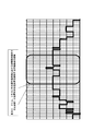
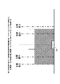
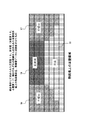
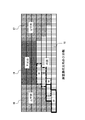
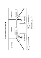
図1乃至図75は実施の形態1を示す図で、図1、図2は空気調和機100の斜視図、図3は空気調和機100の縦断面図、図4は赤外線センサ3と受光素子の各配光視野角を示す図、図5は赤外線センサ3を収納する筐体5の斜視図、図6は赤外線センサ3付近の斜視図((a)は赤外線センサ3が右端端部へ可動した状態、(b)は赤外線センサ3が中央部へ可動した状態、(c)は赤外線センサ3が左端端部へ可動した状態)、図7は赤外線センサ3の縦断面における縦配光視野角を示す図、図8は主婦12が幼児13を抱いている部屋の熱画像データを示す図、図9は空気調和機100の能力帯により規定された冷房運転時の畳目安ならびに広さ(面積)を示す図、図10は図9記載の能力毎の広さ(面積)の最大面積を用いることで、能力毎における床面の広さ(面積)を規定した図、図11は能力2.2kwにおける縦横の部屋形状制限値を示す図、図12は空気調和機100の能力帯から求まる縦横距離条件を示す図、図13は能力2.2kw時の中央据付時条件を示す図、図14は能力2.2kw時の左コーナー据付時(ユーザーから見て)の場合を示す図、図15は空気調和機100の能力2.2kw時に、リモコンの据付位置ボタンが中央に設定された際の熱画像データ上の床面と壁面との位置関係を示す図、図16は温度ムラによる部屋形状の算出フローを示す図、図17は図15の熱画像データ上にて壁面と床面との境界となる上下の画素間を示す図、図18は図17にて設定した境界線60の位置に対し、下方向に1画素そして上方向に2画素の合計3画素間において上下画素間の生じている温度を検知する図、図19は画素検知領域内において、温度ムラ境界を検知する温度ムラ境界検知部53により閾値を超えた画素、または、傾きの最大値を超えた画素を黒色にてマーキングしている図、図20は温度ムラによる境界線を検知した結果を示す図、図21は熱画像データ上において、境界線の下部に引かれた各素子の座標点(X,Y)を床面座標変換部55が床面座標点として変換し、床面18に投影した図、図22は能力2.2KW、リモコン中央据付条件時における初期設定条件での正面壁19位置付近の温度差を検知する対象画素の領域を示す図、図23は床面18に各熱画像データの境界線素子座標を投影した図21において、図22に示した正面壁19位置付近を検知する各素子の散布素子座標点の平均を求め正面壁19と床面18との壁面位置を求めた図、図24は人体検知位置履歴による部屋形状の算出フローを示す図、図25は直前の背景画像と人体の存在する熱画像データとの差分を行い、閾値A並びに閾値Bをもって人体の検知を判断する結果を示す図、図26は熱画像データ差分から求めた人体検知位置を床面座標変換部55にて座標変換を行った人位置座標(X,Y)点として、X軸、Y軸毎にカウント積算した様子を示す図、図27は人体位置履歴による部屋形状の判定結果を示す図、図28はL字型部屋形状のリビングにおける人体検知位置履歴の結果を示す図、図29は横方向X座標における、床面領域(X座標)に蓄積されたカウント数を示す図、図30は図29にて求めた床面領域(X座標)を領域A・B・Cと均等3分割を行い、蓄積された最大の蓄積数値がどこの領域に存在するかを求め、同時に各領域毎の最大値と最小値を求める図、図31は領域C内に蓄積データの最大蓄積数が存在する場合、最大蓄積数に対して90%以上のカウント数が領域内にγ本(0.3m毎に分解される領域の中の数)以上あることをもって判断する手段を示す図、図32は領域A内に蓄積データの最大蓄積数が存在する場合、最大蓄積数に対して90%以上のカウント数が領域内にγ本(0.3m毎に分解される領域の中の数)以上あることをもって判断する手段を示す図、図33はL字型部屋形状であると判断された場合、最大の蓄積数に対し50%以上の個所を求める図、図34は図33にて求めたL字型部屋形状の床面と壁面との境界点と閾値A以上におけるX座標、Y座標の床面領域から求めたL字型部屋形状の床面領域形状を示す図、図35は三つの情報を統合するフローを示す図、図36は能力2.8kw、リモコン据付位置条件中央にて温度ムラ検知による部屋形状の結果を示す図、図37は左壁面16までの距離が左壁最大の距離を超えている状態である場合は、左壁最大の位置まで縮小させた結果を示す図、図38は修正後の図37の部屋形状面積が面積最大値19m2以上に大きな場合は、正面壁19の距離を最大面積19m2になるまで下げて調整した結果を示す図、図39は左壁面までの距離が左壁最小に満たない場合に左壁最小の領域まで拡大することにより調整した結果を示す図、図40は修正後の部屋形状面積を算出することにより適正面積内にあるか否を判断する例を示す図、図41は各壁面間距離である、正面壁19までの距離Y座標Y_front、右壁面17のX座標X_right、左壁面16のX座標X_leftを求めた結果を示す図、図42は統合条件にて求められた正面壁19、左右壁(左壁面16、右壁面17)間のそれぞれの距離から求められた床面境界線上の各座標点を熱画像データに逆投影させた図、図43それぞれの各壁領域を太線で囲った図、図44は床面18の手前側領域に対して左右方向5分割の領域(A1、A2、A3、A4、A5)に分けた図、図45は床面の奥側領域に対して前後3分割の領域(B1、B2、B3)に分けた図、図46は計算式にて求めた輻射温度の一例を示す図、図47はカーテンの開閉状態を検知する動作のフローチャート図、図48は暖房運転時の右壁面の窓のカーテンが開いている状態のときの熱画像データを示す図、図49は図47に情報提示部を追加したフローチャート図、図50は表示部100aを有する空気調和機100の外観図、図51はリモコン200を示す平面図、図52はリモコン200側のガイダンス表示部220に表示される内容を示すフローチャート図、図53はリモコン200側のガイダンス表示部220に、“ただいま運転開始準備中です” といった内容が表示される図、図54はリモコン200側のガイダンス表示部220に、“設定温度に近づけています” といった内容が表示される図、図55はリモコン200側のガイダンス表示部220に、“設定を元に戻しますか?” といった内容が表示される図、図56は暖房運転時において窓からの冷輻射の影響が大きいと空気調和機100が判断した場合のリモコン200のガイダンス表示部220に表示される表示内容を示す図、図57は冷房運転中に知らないうちに外気温度が室内設定温度より下がった場合のリモコン200のガイダンス表示部220に表示される表示内容を示す図、図58は赤外線センサ3より得られる省エネアドバイスの冷房・除湿運転時の詳細内容を示す図、図59は赤外線センサ3より得られる省エネアドバイスの暖房運転時の詳細内容を示す図、図60は変形例のリモコン300の外観正面図、図61はリモコン300のインターフェイス表示部301にシーンセレクト画面が表示され、カーソルが「急いで冷やしたい」にある状態を示す図、図62はリモコン300のインターフェイス表示部301にシーンセレクト画面が表示され、カーソルが「空気をキレイにしたい」に移動した状態を示す図、図63はリモコン300のインターフェイス表示部301にシーンセレクト画面が表示され、カーソルが「お客様をもてなしたい」に移動した状態を示す図、図64はリモコン300のインターフェイス表示部301に通常画面が表示された状態を示す図、図65はリモコン300のインターフェイス表示部301にシーンセレクト画面(メニュー画面)が表示され、ユーザーがシーンを選択するまでの状態を示す図((a)はカーソルが「急いで冷やしたい」にある状態、(b)はカーソルが「風にあたりたくない」にある状態、(c)はカーソルが「お客様をもてなしたい」にある状態)、図66はリモコン300のインターフェイス表示部301に、「シーン内容」、「シーン詳細設定」が表示された状態を示す図((d)は「シーン内容」、(e)〜(g)は「シーン詳細設定」)、図67はシーンセレクト「空気をキレイにしたい」のアニメーションを示す図、図68はシーンセレクト「お肌をケアしたい」のアニメーションを示す図、図69はシーンセレクトの内容を複数選択したときのシーンセレクト選択画面の拡大図、図70はリモコン300のインターフェイス表示部301に、「急いで冷やし、空気をキレイにしたい」のように組み合わせたシーンセレクトが表示された状態を示す図、図71はリモコン300のインターフェイス表示部301に、暖房運転時の「ソフト省エネ効果を教える」の省エネアドバイスを一括表示する図、図72はリモコン300のインターフェイス表示部301に、暖房運転時の「人の動きを検知し、滞留が一定時間を超えている場合は、人が集まった方が省エネ運転が可能な事を教える」の省エネアドバイスを一括表示する図、図73はリモコン300のインターフェイス表示部301に、暖房運転時の「ムーブアイでの夏の日射、冬の低い輻射でドア/カーテンの開閉を確認し閉めることをすすめる」の省エネアドバイスを一括表示する図、図74はリモコン300のインターフェイス表示部301に、暖房運転時の「足元が寒いお客さんに対してのワンポイントアドバイス」の省エネアドバイスを一括表示する図、図75はリモコン300のインターフェイス表示部301に、暖房運転時の「活動量を検知したときのアドバイス」の省エネアドバイスを一括表示する図である。
1 to 75 are diagrams showing the first embodiment. FIGS. 1 and 2 are perspective views of the
図76乃至図79は比較のために示す図で、図76は一般的なリモコン200の扉閉時の側面図、図77は一般的なリモコン200の扉開時の側面図、図78は一般的なリモコン200の扉閉時の正面図、図79は一般的なリモコン200の扉開時の正面図である。
76 to 79 are diagrams for comparison, FIG. 76 is a side view of the general
図1乃至図3により、空気調和機100(室内機)の全体構成を説明する。図1、図2共に、空気調和機100の外観斜視図であるが、見る角度が異なる点と、図1は上下フラップ43(上下風向制御板、左右に2個)が閉じているのに対して、図2は上下フラップ43が開き奥の左右フラップ44(左右風向制御板、多数)が見えている点とが異なる。
The overall configuration of the air conditioner 100 (indoor unit) will be described with reference to FIGS. 1 to 3. 1 and FIG. 2 are external perspective views of the
図1に示すように、空気調和機100(室内機)は、略箱状の室内機筺体40(本体と定義する)の上面に部屋の空気を吸い込む吸込口41が形成されている。
As shown in FIG. 1, the air conditioner 100 (indoor unit) has a
また、前面の下部に調和空気を吹き出す吹出口42が形成されていて、吹出口42には吹き出し風の風向を制御する上下フラップ43と、左右フラップ44とが設けられる。上下フラップ43は吹き出し風の上下風向を制御し、左右フラップ44は吹き出し風の左右風向を制御する。
Moreover, the
室内機筺体40の前面の下部で、吹出口42の上に、赤外線センサ3が設けられている。赤外線センサ3は、俯角約24.5度の角度で下向きに取り付けられている。
The
俯角とは、赤外線センサ3の中心軸と水平線とがなす角度である。別の言い方をすると、赤外線センサ3は、水平線に対して約24.5度の角度で下向きに取り付けられている。
The depression angle is an angle formed by the central axis of the
図3に示すように、空気調和機100(室内機)は、内部に送風機45を備え、該送風機45を囲むように熱交換器46が配置されている。
As shown in FIG. 3, the air conditioner 100 (indoor unit) includes a
熱交換器46は、室外機(図示せず)に搭載された圧縮機等と接続されて冷凍サイクルを形成している。冷房運転時は蒸発器として、暖房運転時は凝縮器として動作する。
The
吸込口41から送風機45により室内空気が吸い込まれ、熱交換器46で冷凍サイクルの冷媒と熱交換を行い、送風機45を通過して吹出口42から室内へ吹き出される。
Room air is sucked in by the
吹出口42では、上下フラップ43と左右フラップ44とにより、上下方向及び左右方向の風向が制御される。図3は、上下フラップ43が閉じている。
At the
図4に示すように、赤外線センサ3は、金属缶1内部に8個の受光素子(図示せず)を縦方向に一列に配列している。金属缶1の上面には、8個の受光素子に赤外線を通すためのレンズ製の窓(図示せず)が設けられている。各受光素子の配光視野角2は、縦方向7度、横方向8度である。尚、各受光素子の配光視野角2が、縦方向7度、横方向8度のものを示したが、縦方向7度、横方向8度に限定されるものではない。各受光素子の配光視野角2に応じて、受光素子の数は変化する。例えば、1個の受光素子の縦配光視野角と受光素子の数との積が一定になるようにすればよい。
As shown in FIG. 4, the
図4では、1個の受光素子の縦配光視野角が7度、縦方向に一列に配列している受光素子の数が8個であるから、その積は、56である。従って、例えば、1個の受光素子の縦配光視野角が4度、縦方向に一列に配列している受光素子の数が14個でもよい。 In FIG. 4, since the vertical light distribution viewing angle of one light receiving element is 7 degrees and the number of light receiving elements arranged in a line in the vertical direction is 8, the product is 56. Therefore, for example, the vertical light distribution viewing angle of one light receiving element may be 4 degrees, and the number of light receiving elements arranged in a line in the vertical direction may be 14.
図5は、赤外線センサ3付近を裏側(空気調和機100の内部から)から見た斜視図である。図5に示すように、赤外線センサ3は、筐体5内に収納されている。そして、筐体5の上方に赤外線センサ3を駆動するステッピングモーター6が設けられる。筐体5と一体の取付部7が空気調和機100の前面下部に固定されることにより、赤外線センサ3が空気調和機100に取り付けられる。赤外線センサ3が空気調和機100に取り付けられた状態では、ステッピングモーター6と筐体5は垂直である。そして、筐体5の内部で赤外線センサ3が、俯角約24.5度の角度で下向きに取り付けられている。
FIG. 5 is a perspective view of the vicinity of the
ステッピングモーターは、パルス電力に同期して動作する同期電動機である。したがってパルスモーターとも言われる。簡単な回路構成で、正確な位置決め制御を実現できるので、装置の位置決めを行う場合などによく使われる。 The stepping motor is a synchronous motor that operates in synchronization with pulse power. Therefore, it is also called a pulse motor. Since accurate positioning control can be realized with a simple circuit configuration, it is often used when positioning the device.
赤外線センサ3は、ステッピングモーター6により左右方向に所定角度範囲を回転駆動する(このような回転駆動をここでは、可動する、と表現する)が、図6に示すように右端端部(a)から略中央部(b)を経由して左端端部(c)まで可動し、左端端部(c)に来ると逆方向に反転して可動する。この動作を繰り返す。赤外線センサ3は、部屋の温度検出対象範囲を左右に走査しながら温度検出対象の温度を検出する。
The
ここで、赤外線センサ3による部屋の壁や床の熱画像データの取得方法について述べる。尚、赤外線センサ3等の制御は、所定の動作がプログラムされたマイクロコンピュータによって行われる。所定の動作がプログラムされたマイクロコンピュータを制御部と定義する。以下の説明では、一々夫々の制御を制御部(所定の動作がプログラムされたマイクロコンピュータ)が行うという記載は省略する。
Here, a method for acquiring thermal image data of the wall or floor of the room by the
部屋の壁や床の熱画像データを取得する場合、赤外線センサ3をステッピングモーター6により左右方向に可動し、ステッピングモーター6の可動角度(赤外線センサ3の回転駆動角度)1.6度毎に各位置で赤外線センサ3を所定時間(0.1〜0.2秒)停止させる。
When acquiring thermal image data of the walls and floors of the room, the
赤外線センサ3を停止した後、所定時間(0.1〜0.2秒より短い時間)待ち、赤外線センサ3の8個の受光素子の検出結果(熱画像データ)を取り込む。
After the
赤外線センサ3の検出結果を取り込み終了後、再びステッピングモーター6を駆動(可動角度1.6度)した後停止し、同様の動作により赤外線センサ3の8個の受光素子の検出結果(熱画像データ)を取り込む。
After capturing the detection results of the
上記の動作を繰り返し行い、左右方向に94箇所の赤外線センサ3の検出結果をもとに検知エリア内の熱画像データを演算する。
The above operation is repeated, and thermal image data in the detection area is calculated based on the detection results of 94
ステッピングモーター6の可動角度1.6度毎に94箇所で赤外線センサ3を停止させて熱画像データを取り込むので、赤外線センサ3の左右方向の可動範囲(左右方向に回転駆動する角度範囲)は、約150.4度である。
Since the
図7は空気調和機100を部屋の床面から1800mmの高さに据付けた状態で、8個の受光素子が縦に一列に配列された赤外線センサ3の縦断面における縦配光視野角を示す。
FIG. 7 shows a vertical light distribution viewing angle in a vertical cross section of the
図7に示す角度7°は、1個の受光素子の縦配光視野角である。
The
また、図7の角度37.5°は、赤外線センサ3の縦視野領域に入らない領域の空気調和機100が取り付けられた壁からの角度を示す。赤外線センサ3の俯角が0°であれば、この角度は、90°−4(水平より下の受光素子の数)×7°(1個の受光素子の縦配光視野角)=62°になる。本実施の形態の赤外線センサ3は、俯角が24.5°であるから、62°−24.5°=37.5°になる。
Further, an angle 37.5 ° in FIG. 7 indicates an angle from a wall to which the
図8は8畳相当の部屋で主婦12が幼児13を抱いている一生活シーンを、赤外線センサ3を左右方向に可動させながら得られた検出結果をもとに熱画像データとして演算した結果を示す。
FIG. 8 shows a result obtained by calculating, as thermal image data, a life scene in which a
図8は季節が冬で、且つ天候が曇りの日に取得した熱画像データである。従って、窓14の温度は、10〜15℃と低い。主婦12と幼児13の温度が最も高い。特に、主婦12と幼児13の上半身の温度は、26〜30℃である。このように、赤外線センサ3を左右方向に可動させることにより、例えば、部屋の各部の温度情報を取得することができる。
FIG. 8 shows thermal image data acquired on a day when the season is winter and the weather is cloudy. Therefore, the temperature of the
次に、空気調和機の能力帯と、空調運転時に生じる床面と壁面との温度差(温度ムラ)情報と、人体検知位置の履歴とから総合判断して部屋形状を決定する部屋形状検知手段(空間認識検知)について述べる。 Next, room shape detection means for determining the room shape by comprehensively judging from the capacity band of the air conditioner, the temperature difference (temperature unevenness) information between the floor surface and the wall surface generated during the air conditioning operation, and the history of the human body detection position (Space recognition detection) will be described.
赤外線センサ3にて取得する熱画像データにより、空調している空調エリア内の床面広さを求め、熱画像上の空調エリア内における壁面位置を求める。
From the thermal image data acquired by the
熱画像上で床面、壁面(壁面とは、空気調和機100から見た正面壁、並びに左右の壁面)の領域が解ることから、個々の壁面平均温度を求めることが可能となり、熱画像上にて検出された人体に対する壁面温度を考慮した精度のよい体感温度を求めることが可能となる。 Since the areas of the floor surface and the wall surface (the wall surfaces are the front wall and the left and right wall surfaces viewed from the air conditioner 100) are understood on the thermal image, it becomes possible to obtain the average temperature of each individual wall surface. Thus, it is possible to obtain an accurate body temperature in consideration of the wall surface temperature detected by the human body.
熱画像データ上で床面広さを求める手段は、下記に示す三つの情報を統合することで、精度のよい床面広さの検知並びに部屋形状を検知可能とする。
(1)空気調和機100の能力帯並びにリモコンの据付位置ボタン設定から求める形状制限値および初期設定値の部屋形状。
(2)空気調和機100の運転中に生じる床と壁の温度ムラから求まる部屋形状。
(3)人体検知位置履歴から求まる部屋形状。
The means for obtaining the floor area on the thermal image data integrates the following three pieces of information to enable accurate detection of the floor area and the room shape.
(1) The room shape of the shape limit value and the initial setting value obtained from the capacity band of the
(2) The room shape obtained from the temperature unevenness of the floor and wall generated during the operation of the
(3) The room shape obtained from the human body detection position history.
空気調和機100は、空調する部屋の広さを基準に対応する能力帯に分けられている。図9は空気調和機100の能力帯により規定された冷房運転時の畳目安ならびに広さ(面積)を示した図である。例えば、空気調和機100の能力2.2kwの場合は、冷房運転時における空調広さの畳目安は6〜9畳となる。6畳から9畳の広さ(面積)は、10〜15m2である。
The
図10は、図9記載の能力毎の広さ(面積)の最大面積を用いることで、能力毎における床面の広さ(面積)を規定した図である。能力2.2kwの場合、図9の広さ(面積)の最大面積は15m2である。15m2の平方根を求めることで縦横比率を1:1とした場合の縦横の距離は各3.9m(3.873m)となる。最大面積15m2を固定し、縦横比率を1:2〜2:1の範囲で可変させた場合の縦横の距離で、縦横の最大距離と最小距離を設定する。 FIG. 10 is a diagram in which the floor area (area) for each capacity is defined by using the maximum area (area) for each capacity shown in FIG. When the capacity is 2.2 kw, the maximum area (area) in FIG. 9 is 15 m 2 . By obtaining the square root of 15 m 2 , the vertical and horizontal distances when the aspect ratio is 1: 1 are 3.9 m (3.873 m) each. The maximum vertical and horizontal distance and the minimum distance are set as vertical and horizontal distances when the maximum area of 15 m 2 is fixed and the aspect ratio is varied in the range of 1: 2 to 2: 1.
図11に、能力2.2kwにおける縦横の部屋形状制限値の図を示す。能力毎の最大面積15m2の平方根より縦横比率1:1の場合の縦横の各距離は3.9mとなる。最大面積15m2を固定し、縦横比率を1:2〜2:1の範囲で可変させた場合の縦横の距離で、縦横の最大距離を設定する。縦横比率1:2の場合は、縦2.7m:横5.5mとなる。同様に縦横比率2:1の場合は、縦5.5m:横2.7mとなる。 FIG. 11 shows a diagram of the room shape limit values in the vertical and horizontal directions with a capacity of 2.2 kw. From the square root of the maximum area of 15 m 2 for each ability, the vertical and horizontal distances when the aspect ratio is 1: 1 are 3.9 m. The maximum vertical and horizontal distance is set as the vertical and horizontal distance when the maximum area of 15 m 2 is fixed and the aspect ratio is varied in the range of 1: 2 to 2: 1. When the aspect ratio is 1: 2, the length is 2.7 m and the width is 5.5 m. Similarly, when the aspect ratio is 2: 1, the length is 5.5 m: width 2.7 m.
図12に空気調和機100の能力帯から求まる縦横距離条件を示す。図12の初期値の値は、能力毎における対応面積の中間面積の平方根から求めている。例えば能力2.2kwの適応面積は10〜15m2となり、中間面積は12m2となる。12m2の平方根より初期値3.5mを求めている。以下能力帯毎における初期値の縦横距離の算出は同様な考え方から求めている。同時に最小値(m)、最大値(m)は図10の算出の通りである。
FIG. 12 shows the vertical and horizontal distance conditions obtained from the capacity band of the
従って、空気調和機100の能力毎により求まる部屋形状の初期値は、図12の初期値(m)を縦横の距離とする。但し、リモコン(遠隔制御装置)からの据付位置条件により空気調和機100の設置位置の原点を可変することとする。
Therefore, the initial value (m) in FIG. 12 is the vertical and horizontal distance as the initial value of the room shape determined by the capacity of the
図13に、能力2.2kw時の中央据付時条件を示す。図13に示すように、初期値の横距離中間地点を空気調和機100の原点とする。空気調和機100の原点は、縦横3.5mの部屋の中央部(横から1.8m)の位置関係となる。
FIG. 13 shows the conditions for central installation when the capacity is 2.2 kW. As shown in FIG. 13, the initial lateral distance intermediate point is set as the origin of the
図14に、能力2.2kw時の左コーナー据付時(ユーザーから見て)の場合を示す。コーナー据付時の場合は、左右に近いほうの壁までの距離を空気調和機100の原点から(横幅の中心点)0.6mの距離とする。 FIG. 14 shows a case where the left corner is installed (viewed from the user) when the capacity is 2.2 kw. In the case of corner installation, the distance to the wall closer to the left and right is 0.6 m from the origin of the air conditioner 100 (the center point of the width).
従って、(1)空気調和機100の能力帯並びにリモコンの据付位置ボタン設定から求める形状制限値および初期設定値の部屋形状は、上記記載の条件にて空気調和機100の能力帯から設定された床面広さに、リモコンの据付位置条件をもって空気調和機100の据付位置を決めることで、赤外線センサ3から取得される熱画像データ上に床面と壁面との境界線を求めることを可能としている。
Accordingly, (1) the capacity band of the
図15に、空気調和機100の能力2.2kw時に、リモコンの据付位置ボタンが中央に設定された際の熱画像データ上の床面と壁面との位置関係を示す。赤外線センサ3側から見て左壁面16、正面壁19、右壁面17、そして床面18が熱画像データ上に示されている様子がうかがえる。初期設定時における能力2.2kwの床面形状寸法は図13に示す通りである。以下、左壁面16、正面壁19、右壁面17をまとめて壁面と呼ぶ。
FIG. 15 shows the positional relationship between the floor surface and the wall surface on the thermal image data when the remote control installation position button is set at the center when the
次に、(2)空気調和機100の運転中に生じる床と壁の温度ムラから求まる部屋形状の算出手段について説明する。図16に、温度ムラによる部屋形状の算出フローを示す。上述の赤外線センサ3を駆動する赤外線センサ駆動部51から、赤外線画像取得部52にて熱画像データとして生成された縦8*横94の熱画像上において、基準壁位置算出部54にて、熱画像データ上における温度ムラ検知を行う範囲を制約することを特徴とする。
Next, (2) a room shape calculating means obtained from the temperature unevenness of the floor and wall that occurs during the operation of the
以下、図15における、空気調和機の能力2.2KW時でリモコン据付条件が中央時条件にて基準壁位置算出部54の機能説明を行う。
In the following, the function of the reference wall
図17は、図15の熱画像データ上に壁面(左壁面16、正面壁19、右壁面17)と床面18との境界となる上下の画素間の境界線60を示している。境界線60より上の画素が壁面温度を検知する配光画素となり、境界線60より下側の画素が床面温度を検知する配光画素となる。
FIG. 17 shows a
そして、図18において、図17にて設定した境界線60の位置に対し、下方向に1画素そして上方向に2画素の合計3画素間において、上下画素間の生じている温度を検知することを特徴とする。
In FIG. 18, the temperature generated between the upper and lower pixels is detected in a total of three pixels, one pixel in the downward direction and two pixels in the upward direction, with respect to the position of the
全熱画像データすべての画素間にて温度差を探すのではなく、壁面(左壁面16、正面壁19、右壁面17)と床面18との境界線60上を中心に温度差を検知して壁面と床面18との境界線60上に生じる温度を検知することを特徴とする。
Instead of searching for a temperature difference between all the pixels of all the thermal image data, a temperature difference is detected around the
これにより、全画素検知による余分なソフト演算処理の低減(演算処理時間の短縮と負荷低減)と誤検知処理(ノイズデバンス処理)を併せ持つことを特徴とする。 Accordingly, the present invention is characterized in that it has both a reduction in extra software calculation processing (reduction in calculation processing time and load reduction) and an erroneous detection processing (noise debounce processing) due to all pixel detection.
次に上記記載の画素間領域に対する、温度ムラによる境界を検知する温度ムラ境界検知部53は、
(a)床面温度と壁面温度の熱画像データから得られる絶対値による判断手段、
(b)検知領域内における上下画素間における温度差の奥行き方向における傾き(1次微分)の最大値による判断手段、(c)検知領域内における上下画素間における温度差の奥行き方向における傾きの傾き(2次微分)の最大値による判断手段、
のいずれか一つの手段により境界線60を検知可能とすることを特徴とする。
Next, a temperature unevenness
(A) Judging means based on absolute values obtained from thermal image data of floor surface temperature and wall surface temperature,
(B) Judgment means based on the maximum value of the gradient (first derivative) in the depth direction of the temperature difference between the upper and lower pixels in the detection region, (c) The gradient of the gradient in the depth direction of the temperature difference between the upper and lower pixels in the detection region Judgment means based on the maximum value of (secondary derivative),
The
図19は、上記画素検知領域内において、温度ムラ境界を検知する温度ムラ境界検知部53により閾値を超えた画素、または、傾きの最大値を超えた画素を太線のハッチングにてマーキングしている。また、上記の温度ムラ境界を検知する閾値または最大値を超えない個所については、マーキングを実施してはいないことを特徴とする。
In FIG. 19, in the pixel detection area, a pixel that exceeds a threshold value or a pixel that exceeds the maximum value of the slope is marked by thick line hatching by the temperature unevenness
図20は、温度ムラによる境界線を検知した結果を示す。画素間の境界線を線引きする条件は、温度ムラ境界検知部53において、閾値または最大値を超えたマーキングされた画素の下部、そして検知領域のおける上下画素間において閾値または、最大値を超えていない列においては、図17にて基準壁位置算出部54にて初期設定を行った画素間の基準位置にて線引きすることを条件とする。
FIG. 20 shows the result of detecting a boundary line due to temperature unevenness. The condition for drawing the boundary line between pixels exceeds the threshold value or the maximum value in the temperature unevenness
そして、熱画像データ上において、境界線の下部に引かれた各素子の座標点(X,Y)を、床面座標変換部55が床面座標点として変換し、床面18に投影したものが図21となる。94列分の境界線60の下部に引かれた素子座標が投影される結果となることが理解できる。
Then, on the thermal image data, the coordinate point (X, Y) of each element drawn below the boundary line is converted as a floor surface coordinate point by the floor surface coordinate
図22は、能力2.2kw、リモコン中央据付条件時における初期設定条件での正面壁19位置付近の温度差を検知する対象画素の領域66を示す。
FIG. 22 shows a region 66 of a target pixel for detecting a temperature difference in the vicinity of the position of the
先に、床面18に各熱画像データの境界線素子座標を投影した図21において、図22に示した正面壁19位置付近を検知する各素子の散布素子座標点の平均を求め正面壁19と床面18との壁面位置を求めたものが図23の正面壁境界線122となる。
First, in FIG. 21 in which the boundary element coordinates of each thermal image data are projected on the
正面壁境界線線引き手段と同様な考え方で、右壁面17並びに左壁面16に対応する各素子の散布素子座標点の平均で境界線を引くこととする。図23の左壁面境界線120、右壁面境界線121が、各素子の散布素子座標点の平均で引かれた境界線である。そして左右の左壁面境界線120、右壁面境界線121と正面壁境界線122とを結んだ領域が床面領域となる。
In the same way as the front wall boundary line drawing means, the boundary line is drawn with the average of the scattering element coordinate points of each element corresponding to the
また、より温度ムラ検知による精度のよい床壁境界線を線引きする手段として、図22にて正面境界線を求める領域の素子座標Yの平均値と標準偏差σを求めることで、σ値が閾値以下になる素子対象のみで平均値を再計算する手段もある。 Further, as means for drawing a more accurate floor wall boundary line by detecting temperature unevenness, the average value of the element coordinates Y and the standard deviation σ of the area for which the front boundary line is obtained in FIG. There is also a means for recalculating the average value only with the following element target.
同様に左右壁面境界線算出においても、各素子座標Xの平均値と標準偏差σを用いることは可能である。 Similarly, in calculating the left and right wall boundary lines, it is possible to use the average value of each element coordinate X and the standard deviation σ.
また、左右壁面境界線を算出する他の一つの手段は、正面壁境界線算出により求まったY座標、つまり空気調和機100据付け側の壁面からの距離に対して、Y座標間距離の中間領域1/3〜2/3に分布された各素子のX座標の平均を用いて左右壁面間の境界線を求めることも可能である。いずれの場合においても問題がない。
Another means for calculating the left and right wall boundary lines is an intermediate region of the distance between the Y coordinates with respect to the Y coordinate obtained by calculating the front wall boundary line, that is, the distance from the wall surface on the
上記手段による正面左右壁位置算出部56にて求めることができた空気調和機100の据付位置を原点とした正面壁19までの距離Yと、左壁面16までの距離X_leftと、右壁面17までの距離X_rightとを検知履歴蓄積部57にて各距離総和として積算すると共に距離検出カウンタとして回数を積算していき、検知距離の総和とカウント数との割り算をもって平均化された距離を求めることとする。左右壁についても同様な手段にて求めるものとする。
The distance Y to the
尚、検知履歴蓄積部57にてカウントする検知回数が閾値回数より多くなっている場合に限り、温度ムラによる部屋形状の判定結果を有効とする。
Note that the room shape determination result due to temperature unevenness is valid only when the number of detections counted by the detection
次に、(3)人体検知位置履歴から求まる部屋形状の算出について説明する。図24に人体検知位置履歴による部屋形状の算出フローを示す。人体検出部61は、赤外線センサ3を駆動する赤外線センサ駆動部51の出力から赤外線画像取得部52にて熱画像データとして生成された縦8*横94の熱画像データを、直前の熱画像データとの差分を取ることで人体の位置を判断することを特徴としている。
Next, (3) Calculation of the room shape obtained from the human body detection position history will be described. FIG. 24 shows a flow of calculating the room shape based on the human body detection position history. The human
人体の有無ならびに人体の位置を検出する人体検出部61は、熱画像データの差分を取る際に、人体の比較的表面温度の高い頭部付近を差分検知可能とする閾値Aと、やや表面温度の低い足元部分の差分検知可能とする閾値Bを個々に持つことを特徴としている。
The human
図25は、人体の存在する熱画像データが生成される直前の背景画像と人体の存在する熱画像データとの差分を行い、閾値A並びに閾値Bをもって人体の検知を判断している。閾値Aを超える素子を有する熱画像データの熱画像差分領域を人体頭部付近と判断し、閾値Aにて求めた領域に隣接する閾値Bを超える素子を有する熱画像データの熱画像差分領域を求める。その際、閾値Bにて求まる熱画像差分領域は、閾値Aにて求められた熱画像差分領域に隣接していることを前提とする。つまり、閾値Bを超えたのみの熱画像差分領域は人体とは判断しない。熱画像データ間の差分閾値の関係は、閾値A>閾値Bとなることを示す。 In FIG. 25, the difference between the background image immediately before the generation of the thermal image data in which the human body exists and the thermal image data in which the human body exists is determined, and the detection of the human body is determined based on the threshold A and the threshold B. The thermal image difference area of the thermal image data having elements exceeding the threshold A is determined to be near the human head, and the thermal image difference area of the thermal image data having elements exceeding the threshold B adjacent to the area obtained by the threshold A Ask. At this time, it is assumed that the thermal image difference area obtained from the threshold value B is adjacent to the thermal image difference area obtained from the threshold value A. That is, the thermal image difference area that only exceeds the threshold B is not determined to be a human body. The difference threshold relationship between the thermal image data indicates that threshold A> threshold B.
この手段により求めた人体の領域は、人体の頭部から足元までの領域を検知することを可能とし、人体の足元個所を示す熱画像差分領域最下端部の中央部分の熱画像座標X、Y(図25の網掛けの△印の部分の座標)を持って人体位置座標(X,Y)とする。 The region of the human body obtained by this means makes it possible to detect the region from the head of the human body to the feet, and the thermal image coordinates X, Y of the central portion of the lowermost end portion of the thermal image difference region indicating the feet of the human body The coordinates of the human body position (X, Y) are taken by holding (the coordinates of the shaded Δ marks in FIG. 25).
熱画像データの差分により求められた人体の足元位置座標(X,Y)を、先の温度ムラ検知時に説明した図21のように、床面座標点として変換する床面座標変換部55を介して、人体位置履歴蓄積部62は人体位置履歴を蓄積していくことを特徴とする。
The human foot position coordinate (X, Y) obtained from the difference in the thermal image data is converted through the floor surface coordinate
図26は熱画像データ差分から求めた人体検知位置を床面座標変換部55にて座標変換を行った人位置座標(X,Y)点として、X軸、Y軸毎にカウント積算した様子を示す。人体位置履歴蓄積部62において、図26に示すように、横方向X座標並びに奥行きY座標の最小分解は0.3m毎とする領域を確保し、軸毎に0.3m間隔にて確保された領域に人位置検知毎に発生する位置座標(X,Y)を、当てはめカウントしていくものとする。
FIG. 26 shows a state where the human body detection position obtained from the thermal image data difference is counted and integrated for each of the X axis and Y axis as the human position coordinate (X, Y) point subjected to coordinate conversion by the floor surface coordinate
この人体位置履歴蓄積部62からの人体検知位置履歴情報により、部屋形状である床面18、壁面(左壁面16、右壁面17、正面壁19)を壁位置判断部58にて求める。
Based on the human body detection position history information from the human body position
図27は人体位置履歴による部屋形状の判定結果を示す。横方向X座標並びに奥行きY座標に蓄積された最大の蓄積数値に対して10%以上の領域の範囲をもって床面領域と判断することを特徴とする。 FIG. 27 shows the room shape determination result based on the human body position history. The floor area is determined to have a range of 10% or more of the maximum accumulated numerical value accumulated in the horizontal X coordinate and the depth Y coordinate.
次に、人体検知位置履歴の蓄積データから部屋形状が長方形(正方形)なのか、L字型形状であるのかを推定し、L字型部屋形状の床面18と壁面(左壁面16、右壁面17、正面壁19)付近の温度ムラを検知することで精度のよい部屋形状を算出する例を説明する。
Next, it is estimated from the accumulated data of the human body detection position history whether the room shape is rectangular (square) or L-shaped, and the
図28は、L字型部屋形状のリビングにおける人体検知位置履歴の結果を示す。横方向X座標並びに奥行きY座標の最小分解は0.3m毎とする領域を確保され、軸毎に0.3m間隔にて確保された領域に人体検知毎に発生する位置座標(X,Y)を当てはめカウントしていくものである。 FIG. 28 shows the result of the human body detection position history in an L-shaped room-shaped living room. The minimum resolution of the horizontal X coordinate and the depth Y coordinate is an area that is set every 0.3 m, and the position coordinates (X, Y) that are generated every time human body is detected in an area that is secured at intervals of 0.3 m for each axis. Will be counted.
当然、人体はL字の部屋形状内を移動することから、左右方向の床面領域(X座標)並びに奥行方向の床面領域(Y座標)に蓄積されるカウント数は、各X,Y座標毎の奥行き領域(面積)に比例する形になる。 Naturally, since the human body moves within the L-shaped room shape, the number of counts accumulated in the floor area (X coordinate) in the left and right direction and the floor area (Y coordinate) in the depth direction is the X and Y coordinates. The shape is proportional to each depth region (area).
人体検知位置履歴の蓄積データから部屋形状が長方形(正方形)なのか、L字型形状であるのか判断する手段を説明する。 A means for determining whether the room shape is rectangular (square) or L-shaped from the accumulated data of the human body detection position history will be described.
図29は、横方向X座標における、床面領域(X座標)に蓄積されたカウント数を示している。閾値Aは蓄積された最大の蓄積数値に対して10%以上をもって床面X方向の距離(幅)とすることを特徴としている。 FIG. 29 shows the number of counts accumulated in the floor area (X coordinate) in the horizontal direction X coordinate. The threshold A is characterized in that the distance (width) in the floor surface X direction is 10% or more with respect to the maximum accumulated numerical value.
そして、図30に示すように、図29にて求めた床面領域(X座標)を領域A・B・Cと均等3分割を行い、蓄積された最大の蓄積数値がどこの領域に存在するかを求め、同時に各領域毎の最大値と最小値を求ることを特徴としている。 Then, as shown in FIG. 30, the floor surface area (X coordinate) obtained in FIG. 29 is equally divided into three areas A, B, and C, and the maximum accumulated numerical value accumulated exists in which area. This is characterized in that the maximum value and the minimum value for each region are obtained at the same time.
蓄積された最大の蓄積数値が領域C(または領域A)に存在し、領域C内における最大値と最小値との差がΔα以内であることと、領域Cの最大蓄積数値と領域A内における最大蓄積数との差がΔβ以上のとき、L字型部屋形状であると判断する。 The accumulated maximum accumulated numerical value exists in the region C (or region A), the difference between the maximum value and the minimum value in the region C is within Δα, and the maximum accumulated numerical value in the region C and in the region A When the difference from the maximum accumulation number is equal to or greater than Δβ, it is determined that the shape is L-shaped.
各領域毎の最大値と最小値との差Δαを求めることは、人体検知位置履歴の蓄積データから部屋形状を推定するためのノイズデバンス処理の一つである。図31に示すように、領域C内に蓄積データの最大蓄積数が存在する場合、最大蓄積数に対して90%以上のカウント数が領域内にγ本(0.3m毎に分解される領域の中の数)以上あることをもって判断する手段もある。領域Cにて上記演算処理を実施後、領域Aにても同様な演算を行うことでL字型部屋形状であることを判断する(図32参照)。 Obtaining the difference Δα between the maximum value and the minimum value for each region is one of noise debounce processes for estimating the room shape from the accumulated data of the human body detection position history. As shown in FIG. 31, when there is a maximum accumulation number of accumulated data in the area C, the count number of 90% or more of the maximum accumulation number is γ (area decomposed every 0.3 m). There is also a means to judge when there are more than the number). After performing the above calculation process in the area C, the same calculation is performed in the area A to determine the L-shaped room shape (see FIG. 32).
上記によりL字型部屋形状であると判断された場合は、図33に示すように、最大の蓄積数に対し50%以上の個所を求める。本説明は横方向のX座標をもって説明しているが、奥行き方向のY座標における蓄積データにおいても同様である。 If it is determined that the room has an L-shaped room shape as described above, as shown in FIG. 33, a location of 50% or more with respect to the maximum accumulation number is obtained. Although this description is given with the X coordinate in the horizontal direction, the same applies to the accumulated data in the Y coordinate in the depth direction.
横方向のX座標並びに、奥行き方向のY座標の床面領域における最大の蓄積数に対する50%以上の閾値Bを境とする座標点をL字型部屋形状の床と壁面との境界点であると判断することを特徴とする。 A coordinate point with a threshold value B of 50% or more with respect to the maximum accumulation number in the floor area of the horizontal X coordinate and the Y coordinate in the depth direction is a boundary point between the floor and wall surface of the L-shaped room shape. It is characterized by judging.
図34は、図33にて求めたL字型部屋形状の床面と壁面との境界点と閾値A以上におけるX座標、Y座標の床面領域から求めたL字型部屋形状の床面領域形状を示す。 FIG. 34 shows the floor area of the L-shaped room shape obtained from the boundary surface between the floor surface and the wall surface of the L-shaped room shape obtained in FIG. Show shape.
上記で求めたL字型形状の床面形状結果を温度ムラ部屋形状アルゴリズムにおける基準壁位置算出部54にフィードバックし、熱画像データ上における温度ムラ検知を行う範囲を再計算させることを特徴とする。
The L-shaped floor shape result obtained above is fed back to the reference wall
次に部屋形状を求める三つの情報を統合する方法について説明する。但し、L字型形状の床面形状結果を温度ムラ部屋形状アルゴリズムにおける基準壁位置算出部54にフィードバックし、熱画像データ上における温度ムラ検知を行う範囲を再計算させる処理は、ここでは除く。
Next, a method for integrating three pieces of information for determining the room shape will be described. However, the process of feeding back the L-shaped floor shape result to the reference wall
図35に、以下の三つの情報を統合するフローを示す。
(1)空気調和機100の能力帯並びにリモコンの据付位置ボタン設定から求める形状制限値および初期設定値の部屋形状。
(2)空気調和機100の運転中に生じる床と壁の温度ムラから求まる部屋形状。
(3)人体検知位置履歴から求まる部屋形状。
FIG. 35 shows a flow for integrating the following three pieces of information.
(1) The room shape of the shape limit value and the initial setting value obtained from the capacity band of the
(2) The room shape obtained from the temperature unevenness of the floor and wall generated during the operation of the
(3) The room shape obtained from the human body detection position history.
(2)空気調和機100運転中に生じる床面18と壁面との温度ムラから求まる部屋形状は、温度ムラ境界検知部53により検知履歴蓄積部57にてカウントする検知回数が閾値回数より多くなっている場合に限り、温度ムラ有効性判定部64にて、温度ムラによる部屋形状の判定結果を有効とする。
(2) For the room shape obtained from the temperature unevenness between the
同様に、(3)人体検知位置履歴から求まる部屋形状、による人体位置履歴蓄積部62から求まる部屋形状も、人体位置履歴蓄積部62が人体位置履歴を蓄積する人体検知位置履歴回数が閾値回数より多くなっている場合に限り、人体位置有効性判定部63にて、人体検知位置履歴による部屋形状の判定結果を有効とする前提条件のもとで、壁位置判断部58にて下記の条件により判断を行う。
Similarly, as for the room shape obtained from the human body position
イ.(2)と(3)共に無効の場合は、(1)による空気調和機100の能力帯並びにリモコンの据付位置ボタン設定から求める初期設定値の部屋形状とする。
I. When both (2) and (3) are invalid, the room shape of the initial setting value obtained from the capacity band of the
ロ.(2)が有効で(3)が無効の場合は、(2)による出力結果を部屋形状とする。ただし(2)の部屋形状が(1)の図12にて決まる辺の長さに収まらない場合、または面積に収まらない場合は、その範囲に伸縮させることとする。ただし、面積により伸縮させる場合は、正面壁19までの距離をもって修正させることとする。
B. When (2) is valid and (3) is invalid, the output result of (2) is taken as the room shape. However, if the room shape in (2) does not fit in the length of the side determined in FIG. 12 in (1), or does not fit in the area, it will be expanded or contracted to that range. However, when expanding or contracting depending on the area, the distance to the
具体的な修正方法について説明を行う。能力2.8kw、リモコン据付位置条件中央にて温度ムラ検知による部屋形状の結果を図36に示す。図12より、空気調和機100の能力2.8kw時における縦横の辺の長さの最小値は3.1m、最大値は6.2mとなる。そのためリモコン中央据付条件から、右側の壁面までの距離X_right並びに左側の壁面までの距離X_leftの制限距離は、図12の半分となるように決める。そのため、図中に示した右壁最小/左壁最小の距離は1.5m、右壁最大/左壁最大の距離は3.1mとなる。図36に示した温度ムラによる部屋形状のように、左壁面16までの距離が左壁最大の距離を超えている状態である場合は、図37に示すように左壁最大の位置まで縮小させることとする。
A specific correction method will be described. FIG. 36 shows the result of the room shape by detecting the temperature unevenness at the center of the remote control installation position condition with the capability of 2.8 kW. From FIG. 12, when the capacity of the
同様に、図36に示すように右壁までの距離が右壁最小と右壁最大の間に位置する場合は、そのままの位置関係を維持することとする。図37のように左壁最大に縮小した後、部屋形状の面積を求め、図12に示す能力2.8kw時の面積範囲13〜19m2の適正範囲内になっているか確認する。 Similarly, as shown in FIG. 36, when the distance to the right wall is located between the minimum right wall and the maximum right wall, the positional relationship is maintained as it is. After reducing to the left wall maximum as shown in FIG. 37, the area of the room shape is obtained, and it is confirmed whether it is within the appropriate range of the area range of 13 to 19 m 2 at the capacity of 2.8 kW shown in FIG.
仮に修正後の図37の部屋形状面積が面積最大値19m2以上に大きな場合は、図38に示すように、正面壁19の距離を最大面積19m2になるまで下げることで調整することとする。
If the room shape area of FIG. 37 after correction is larger than the maximum area value 19 m 2 , as shown in FIG. 38, the distance of the
図39に示すケースも同様に、左壁面16までの距離が左壁最小に満たない場合は、左壁最小の領域まで拡大することとなる。
Similarly, in the case shown in FIG. 39, when the distance to the
その後、図40に示すように、修正後の部屋形状面積を算出することにより適正面積内にあるか否を判断することとする。 Thereafter, as shown in FIG. 40, it is determined whether the room area is within the appropriate area by calculating the corrected room shape area.
ハ.(2)が無効で(3)が有効の場合も、(3)による出力結果を部屋形状とする。上記(2)が有効で(3)が無効の場合のロと同様に、(1)で決まる辺の長さ、面積の制限に適合するように修正を行うこととする。 C. Even when (2) is invalid and (3) is valid, the output result of (3) is the room shape. Similarly to the case of (2) valid and (3) invalid, correction is made so as to meet the side length and area restrictions determined by (1).
ニ.(2)、(3)ともに有効の場合は、(2)の温度ムラによる部屋形状を基準として、それより(3)の人体検知位置履歴による部屋形状の方が、壁までの距離が狭い面があった場合は、最大0.5mの幅で(2)の温度ムラによる部屋形状の出力を狭める方向に修正する。 D. When both (2) and (3) are valid, the room shape based on the human body detection position history of (3) has a shorter distance to the wall, based on the room shape due to temperature unevenness of (2). If there is, the correction is made so that the output of the room shape due to the temperature unevenness of (2) is narrowed with a maximum width of 0.5 m.
逆に、(3)の方が広い場合は修正を行わないこととする。そして、修正後の部屋形状に関しても(1)で決まる辺の長さ、面積の制限に適合するように修正を加える。 Conversely, if (3) is wider, no correction is made. The room shape after correction is also corrected so as to conform to the restrictions on the length and area of the side determined in (1).
上記の統合条件より、図41に示すように各壁面間距離である、正面壁19までの距離Y座標Y_front、右壁面17のX座標X_right、左壁面16のX座標X_leftを求めることができる。
From the above integration conditions, as shown in FIG. 41, the distance Y between the wall surfaces, the Y coordinate Y_front to the
次に床壁輻射温度の算出について説明する。上記の統合条件にて求められた正面壁19、左右壁(左壁面16、右壁面17)間のそれぞれの距離から求められた床面境界線上の各座標点を、熱画像データに逆投影させたものを図42に示す。
Next, calculation of the floor wall radiation temperature will be described. Each coordinate point on the floor boundary obtained from the distance between the
図42の熱画像データ上にて、床面18の領域、正面壁19、左壁面16、右壁面17の領域が区切られる様子が理解できる。
It can be understood that the area of the
まず壁面温度の算出に関しては、熱画像データ上にて求められた各壁領域の熱画像データから求まる温度データの平均を壁温度とする。 First, regarding the calculation of the wall surface temperature, the average of the temperature data obtained from the thermal image data of each wall region obtained on the thermal image data is set as the wall temperature.
図43に示すように、各壁領域を太線で囲った領域がそれぞれの各壁領域となる。 As shown in FIG. 43, each wall region is surrounded by a thick line.
次に床面18の温度領域について説明する。熱画像データ上の床面領域を、例えば、左右方向に5分割、奥行き方向に3分割の合計15分割の領域に細分する。尚、分割する領域の数は、これに限定されるものではなく、任意でよい。
Next, the temperature region of the
図44に示す例は、床面18の手前側領域に対して左右方向5分割の領域(A1、A2、A3、A4、A5)に分けたものである。
The example shown in FIG. 44 is divided into five regions (A1, A2, A3, A4, A5) divided in the left-right direction with respect to the near side region of the
同様に図45にて、床面の奥側領域に対して前後3分割の領域(B1、B2、B3)に分けたものである。いずれも領域毎に前後左右の床面領域が重なり合っていることを特徴としている。従って、熱画像データ上には、正面壁19、左壁面16、右壁面17の温度並びに15分割された床面温度の温度データが生成されることとなる。分割された各床面領域の温度は、夫々の平均温度とする。この熱画像データ上に領域分けされた各温度情報をもとに、熱画像データが撮像する居住エリア内における各人体の輻射温度を求めることを特徴とする。
Similarly, in FIG. 45, the area is divided into three front and rear divided areas (B1, B2, B3) with respect to the back side area of the floor. Both are characterized in that front, back, left, and right floor areas overlap each other. Therefore, on the thermal image data, temperature data of the temperature of the
以下に示す計算式にて各人体毎の床面並びに壁面からの輻射温度を求める。 The radiation temperature from the floor surface and wall surface for each human body is obtained by the following calculation formula.

ここで、
T_calc:輻射温度
Tf.ave:人体が検知された場所の床面温度
T_left:左壁面温度
T_front:正面壁温度
T_right:右壁面温度
Xf:人体検知位置のX座標
Yf:人体検知位置のY座標
X_left:左側壁面間距離
Y_front:正面壁面間距離
X_right:右側壁面間距離
α、β、γ:補正係数
here,
T_calc: radiation temperature Tf. ave: floor temperature T_left of the place where the human body is detected: left wall surface temperature T_front: front wall temperature T_right: right wall surface temperature Xf: X coordinate of human body detection position Yf: Y coordinate of human body detection position X_left: distance between left wall surfaces Y_front : Distance between front wall surfaces X_right: Distance between right wall surfaces α, β, γ: Correction coefficient
人体が検知された場所における、床面温度と、各壁面の壁面温度と、各壁面間距離の影響を考慮した輻射温度の算出を行うことが可能となっている。 It is possible to calculate the radiation temperature in consideration of the influence of the floor surface temperature, the wall surface temperature of each wall surface, and the distance between the wall surfaces at the place where the human body is detected.
図46に上記計算式にて求めた輻射温度の一例を示す。熱画像データ上にて被験者A並びに被験者Bが熱画像データ上にて撮像する居住空間内にて検知された条件にて、輻射温度を試算している。正面壁温度T_front:23℃、T_left:15℃、T_right:23℃、被験者Aの床面温度Tf.ave=20℃、被験者Bの床面温度Tf.ave=23℃、輻射温度演算式上の補正係数はすべて1にて計算した結果、被験者Aの輻射温度T_calc=18℃、被験者Bの輻射温度T_calc=23℃と求めることができる。 FIG. 46 shows an example of the radiation temperature obtained by the above formula. The radiation temperature is estimated on the condition detected in the living space where the subject A and the subject B image on the thermal image data on the thermal image data. Front wall temperature T_front: 23 ° C., T_left: 15 ° C., T_right: 23 ° C., subject A floor temperature Tf. ave = 20 ° C., subject B's floor temperature Tf. As a result of calculating ave = 23 ° C. and all correction coefficients on the radiation temperature calculation formula as 1, it can be determined that the radiation temperature of subject A is T_calc = 18 ° C. and the radiation temperature of subject B is T_calc = 23 ° C.
従来床面18のみの温度にて輻射温度を計算していたが、部屋形状を認識することで求められる壁面温度からの輻射温度を考慮することが可能となり、人体が体全体にて体感する輻射温度を求めることが可能となった。
Conventionally, the radiation temperature is calculated based on the temperature of the
次に、上述の部屋形状を認識することで求められる壁面温度を利用して、カーテンの開閉状態を検知する例について説明する。空調中の部屋において、カーテンを開けた状態より閉めた状態の方が空調効率が良い場合が多いため、カーテンを開いていることを検知した場合は、空気調和機100の利用者にカーテンを閉めるように促すことができるようにするためである。
Next, an example in which the open / close state of the curtain is detected using the wall surface temperature obtained by recognizing the above-described room shape will be described. In the air-conditioned room, the air-conditioning efficiency is often better when the curtain is closed than when the curtain is opened. Therefore, when it is detected that the curtain is open, the user of the
図47のフローチャートにより、カーテンの開閉状態を検知するフローについて説明する。 The flow of detecting the curtain open / closed state will be described with reference to the flowchart of FIG.
尚、以下に示す制御は、所定の動作がプログラムされたマイクロコンピュータによって行われる。ここでも、所定の動作がプログラムされたマイクロコンピュータを制御部と定義する。以下の説明では、一々夫々の制御を制御部(所定の動作がプログラムされたマイクロコンピュータ)が行うという記載は省略する。 The following control is performed by a microcomputer programmed with a predetermined operation. Here again, a microcomputer programmed with a predetermined operation is defined as a control unit. In the following description, a description that each control is performed by the control unit (a microcomputer programmed with a predetermined operation) is omitted.
熱画像取得部101は、赤外線センサ3を温度検出対象範囲を左右に走査して温度検出対象の温度を検出することにより熱画像を獲得する。
The thermal
既に述べたように、部屋の壁や床の熱画像データを取得する場合、赤外線センサ3をステッピングモーター6により左右方向に可動し、ステッピングモーター6の可動角度(赤外線センサ3の回転駆動角度)1.6度毎に各位置で赤外線センサ3を所定時間(0.1〜0.2秒)停止させる。赤外線センサ3を停止した後、所定時間(0.1〜0.2秒より短い時間)待ち、赤外線センサ3の8個の受光素子の検出結果(熱画像データ)を取り込む。赤外線センサ3の検出結果を取り込み終了後、再びステッピングモーター6を駆動(可動角度1.6度)した後停止し、同様の動作により赤外線センサ3の8個の受光素子の検出結果(熱画像データ)を取り込む。上記の動作を繰り返し行い、左右方向に94箇所の赤外線センサ3の検出結果をもとに検知エリア内の熱画像データを演算する。
As described above, when acquiring thermal image data of a wall or floor of a room, the
床壁検知部102は、前述の制御部が、赤外線センサ3を走査して部屋の熱画像データを取得し、熱画像データ上で、以下に示す三つの情報を統合することで、空調している空調エリア内の床面広さを求め、熱画像データ上の空調エリア内における壁領域(壁面位置)を獲得する。
(1)空気調和機100の能力帯並びにリモコンの据付位置ボタン設定から求める形状制限値および初期設定値の部屋形状;
(2)空気調和機100の運転中に生じる床と壁の温度ムラから求まる部屋形状;
(3)人体検知位置履歴から求まる部屋形状。
The floor
(1) The room shape of the shape limit value and the initial setting value obtained from the capacity band of the
(2) Room shape obtained from temperature unevenness of floor and wall generated during operation of the
(3) The room shape obtained from the human body detection position history.
熱画像取得部101で獲得した熱画像から、前述の処理で生成した背景熱画像(図43)に対して、以下で説明する温度条件判定部(室温判定部103、外気温判定部104)の処理を適用することにより、現在の温度条件が窓状態の検知が必要な状態かどうかを判定する。
From the thermal image acquired by the thermal
窓状態の検知が必要な状態とは、例えば暖房運転時であれば、室温に対し外気温度が一定温度(例えば5℃)より低く、窓が冷えており、カーテンを開けた状態では暖房効率が悪い状態を示す。 For example, in the case of heating operation, the state where the window state needs to be detected is that the outside air temperature is lower than a certain temperature (for example, 5 ° C.) with respect to the room temperature, the window is cooled, and the heating efficiency is increased when the curtain is opened. Indicates a bad condition.
逆に冷房時であれば、室温に対し外気温度が一定温度(例えば5℃)より高く、窓が温まっており、カーテンを開けた状態では冷房効率が悪い状態を示す。 Conversely, during cooling, the outside air temperature is higher than a certain temperature (for example, 5 ° C.) with respect to room temperature, the window is warmed, and the cooling efficiency is poor when the curtain is opened.
温度条件判定部の室温判定部103は、室温を検知する手段である。室温は、以下に示す方法で概算することができる。
(1)背景熱画像の画像全体の平均温度;
(2)背景熱画像の床領域の平均温度;
(3)空気調和機100の室内機筺体40(本体)の吸込口41に搭載された室温サーミスタ温度計(図示せず)の値。
The room
(1) The average temperature of the entire background thermal image;
(2) Average temperature of the floor area of the background thermal image;
(3) Value of a room temperature thermistor thermometer (not shown) mounted on the
外気温判定部104は、外気温度を検知する手段である。外気温度は、以下に示す方法で概算することができる。
(1)空気調和機100の室外機(図示せず)に搭載の外気温サーミスタ温度計(図示せず)の値;
(2)または、以下の方法で代用しても窓状態の検知が必要な状態かどうかの判定には支障がない。
a.(暖房時)背景熱画像の壁領域中で最も低い温度;
b.(冷房時)背景熱画像の壁領域中で最も高い温度。
The outside air
(1) Value of an outside temperature thermistor thermometer (not shown) mounted on the outdoor unit (not shown) of the
(2) Or even if the following method is used instead, there is no problem in determining whether the window state needs to be detected.
a. The lowest temperature in the wall area of the background thermal image (during heating);
b. (Cooling) The highest temperature in the wall area of the background thermal image.
室温判定部103、外気温判定部104で検知した室温と外気温度の差が一定値(例えば5℃)以上であれば、以下の窓状態検知部へ処理を進める。
If the difference between the room temperature and the outside air temperature detected by the room
窓状態検知部では、背景熱画像中の顕著な温度差(所定の温度差、例えば5℃、)がある領域を窓領域31(図48)として検知し、その窓領域31の時間変化を監視することと同時にカーテンを閉める動作を検知可能とする。
The window state detection unit detects a region having a significant temperature difference (predetermined temperature difference, for example, 5 ° C.) in the background thermal image as the window region 31 (FIG. 48), and monitors the time change of the
例えば、暖房時の室内温度分布を赤外線センサ3で撮影したとき、図48に示すような熱画像が得られる。熱画像の中の右壁面17の低温部分を窓領域31として検知する。図48では、色の濃さで温度の高低を表している。色の濃い方が、温度が低い。
For example, when a room temperature distribution during heating is photographed by the
壁領域内温度差判定部105で、背景熱画像において壁領域内の温度差が一定値(例えば5℃)以上あるかどうかを判定する。壁領域内の温度差は、暖房時、冷房時、部屋の広さ、空調開始後の経過時間等により変化するが、空調時には床温度もしくは室温といった基準温度に対し壁温度は差がある場合が多く、単純に基準温度からの差の閾値処理だけで窓領域31の有無を判定することは難しい。
The wall region temperature
そこで、壁領域内温度差判定部105では、同じ壁内の温度に顕著な差があれば、窓領域31が存在するという考えに基づき壁領域内の温度差の有無を判定する。
Therefore, the wall region temperature
壁領域内温度差判定部105で、壁領域内に顕著な温度差がないとなった場合は窓領域31なしと判定し、以降の処理は行わない。
When the wall area temperature
壁領域内外気温度領域抽出部106で、背景熱画像において壁領域内で外気温度に近い領域を抽出する。つまり冷房時には壁領域内で温度の高い領域を、暖房時には壁領域内で温度が低い領域を抽出する。
The wall region inside / outside temperature
背景熱画像において壁領域内で外気温度に近い領域の抽出方法としては、壁領域内の平均温度に対して一定温度(例えば5℃)以上温度の高い(低い)領域を抽出する方法がある。 As a method of extracting a region close to the outside temperature in the wall region in the background thermal image, there is a method of extracting a region that is higher (lower) than a certain temperature (for example, 5 ° C.) than the average temperature in the wall region.
ただし、壁領域内外気温度領域抽出部106では、微小な領域を誤検出として削除する。例えば、窓の最低サイズを幅80cm×高さ80cmとする。床壁検知部102で検知した床壁の位置と、赤外線センサ3の設置角度とから熱画像上の各位置に窓があった場合の熱画像上の窓のサイズが計算できる。計算で算出した熱画像上の窓のサイズが、窓の最低サイズ以下の広さの領域の場合には、微小な領域として削除する。
However, the wall region inside / outside air temperature
窓領域抽出部107で、壁領域内外気温度領域抽出部106で抽出した領域の中で窓領域31である可能性の高い領域を抽出する。
The window
窓領域抽出部107は、壁領域内外気温度領域抽出部106において、一定時間(例えば10分)以上窓領域31として抽出され続けた領域を窓領域31として検知する。
The window
窓領域内温度差判定部108で、窓領域抽出部107で窓領域31として検知した領域内の温度変化を監視し、窓として判定された領域の温度が壁平均温度付近まで変化したかどうかを判定し、変化があれば窓領域31がなくなったと判定する。
The window region temperature
カーテン閉め動作判定部109で、窓領域抽出部107で検知した窓領域31の全部が、窓領域内温度差判定部108において窓領域31ではないと判定されればカーテンが閉められたと判定する。
When the curtain closing
また、窓領域抽出部107で窓領域31が検知されている状態で、壁領域内温度差判定部105において、窓領域31なしと判定された場合もカーテンが閉められたと判定する。
Further, when the window
以上のように、熱画像取得部101が赤外線センサ3を温度検出対象範囲を左右に走査して温度検出対象の温度を検出するにより熱画像を獲得し、床壁検知部102が熱画像データ上の空調エリア内における壁領域を獲得し、温度条件判定部により現在の温度条件が窓状態の検知が必要な状態かどうかを判定し、検知が必要な状態であれば、窓状態検知部が背景熱画像中の顕著な温度差がある領域を窓領域31として検知し、その窓領域31の時間変化を監視することと同時にカーテンを閉める動作を検知可能とする。
As described above, the thermal
そのように構成することにより、空調に余計な消費電力が必要な状態である外気温の影響を受けた窓の露出を検出し、空気調和機100の利用者に、カーテン等を閉める動作を促すことを可能とする。
With such a configuration, the exposure of the window affected by the outside air temperature, which requires extra power consumption for air conditioning, is detected, and the user of the
空気調和機100の利用者が、カーテン等を閉めることにより、空気調和機100の消費電力を低減することができる。
The user of the
次に、例えば、外気温の影響を受けた窓の露出を検出し、空気調和機100の利用者にカーテン等を閉める動作を促す具体的な方法について説明する。
Next, for example, a specific method for detecting the exposure of the window affected by the outside air temperature and encouraging the user of the
図49のフローチャートは、図47のカーテンの開閉状態を検知するフローチャートに情報提示部(ユーザーインターフェイス部110)を追加したものである。 The flowchart in FIG. 49 is obtained by adding an information presentation unit (user interface unit 110) to the flowchart for detecting the open / closed state of the curtain in FIG.
情報提示部(ユーザーインターフェイス部110)は、ユーザー自身、気が付きにくい又はわからない省エネの情報をユーザーに伝えることで、ユーザーの省エネ行動を促すことを目的とする。 The information presenting unit (user interface unit 110) is intended to promote the user's energy-saving behavior by conveying the user's own energy-saving information that is difficult or unnoticeable to the user.
特に省エネ知識がなくても、リモコン200(図51のガイダンス表示部220に表示された表示内容を参照)に表示されたガイダンス内容を実行することにより、省エネ運転が可能となるものである。
Even if there is no particular knowledge of energy saving, the energy saving operation can be performed by executing the guidance content displayed on the remote controller 200 (see the display content displayed on the
本実施の形態に記述している赤外線センサ3により求まる熱画像から得られる基本情報は、以下の3点である。
(1)居住空間エリア内の人体の位置(部屋の何処に居るのかという検知結果)情報。
(2)時間軸あたりの人体の検知結果から求める人体の活動量(移動量)情報。常に違う場所で人体が検知されているようなときは、活動量(移動量)が大と判定する。逆に同じ場所に滞在する場合(ソファーでリラックしている状態など)は、活動量(移動量)が小と判定する。
(3)空間認識より求めた壁面内のある窓領域31の温度情報。
Basic information obtained from the thermal image obtained by the
(1) Information on the position of the human body in the living space area (detection result of where in the room).
(2) Information on the amount of movement (movement amount) of the human body obtained from the detection result of the human body per time axis. When a human body is always detected in a different place, it is determined that the amount of activity (movement amount) is large. On the contrary, when staying at the same place (such as a state of being relaxed on the sofa), it is determined that the activity amount (movement amount) is small.
(3) Temperature information of a
ユーザーに省エネ行動を促す省エネアドバイスは、この3つの情報を基に実施する。 Energy saving advice that encourages users to save energy is based on these three types of information.
ユーザー自身、気が付きにくい又はわからない省エネの情報を、情報提示部のユーザーインターフェイス部110で伝えることで、ユーザーの省エネ行動を促すことを目的とし、特に省エネ知識がなくてもリモコン200(図51参照)に表示されたガイダンス内容を実行することにより省エネ運転が可能となることを特徴とする。
The user himself / herself does not know or does not know energy saving information through the
以下、ユーザーインターフェイス部110の詳細について記述する。
Details of the
図50に示すように、空気調和機100は、室内機筺体40の前面に表示部100aを備える。表示部100aは、ECOランプ20(ガイダンス表示可能)等を有する。
As shown in FIG. 50, the
ユーザーがわからない(気が付かない)省エネ情報を、赤外線センサ3からの情報を基に得ることができた空気調和機100は、室内機筺体40の表示部100aのECOランプ20(ガイダンス表示可能)を点灯させることで、まずユーザーに省エネの情報があることを告知する。
The
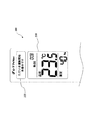
図51に示すリモコン200(遠隔制御装置)は、ユーザーが手元において空気調和機100の運転を制御するものであるが、ここで示すリモコン200は、通常の運転入/切、温度設定等のボタンの他に、ECOアドバイスボタン210(情報要求ボタン)、ガイダンス表示部220を備える。
The remote controller 200 (remote control device) shown in FIG. 51 is for the user to control the operation of the
ユーザーは、空気調和機100(室内機)の表示部100aで点灯するECOランプ20に気が付くことで、リモコン200の操作部に設けられたECOアドバイスボタン210(情報要求ボタン)を押し、詳細な省エネ情報を得ることができる。
The user notices the
空気調和機100(室内機)とリモコン200との間の省エネ情報の受け渡し技術手段は、双方向の赤外線通信でも無線通信でもどちらでもよい。
The energy saving information delivery technology means between the air conditioner 100 (indoor unit) and the
空気調和機100(室内機)は、双方向の赤外線通信もしくは無線通信により、空気調和機100(室内機)の制御部と、リモコン200(遠隔制御装置)との間で双方向通信を行う通信部(図示せず)を備える。 The air conditioner 100 (indoor unit) performs communication that performs bidirectional communication between the control unit of the air conditioner 100 (indoor unit) and the remote controller 200 (remote control device) by bidirectional infrared communication or wireless communication. Part (not shown).
詳細な省エネ情報は、リモコン200の上部のガイダンス表示部220に表示することを特徴とする。
Detailed energy saving information is displayed on the
図51に示すように、リモコン200(遠隔制御装置)は、最上部に省エネ運転情報(おすすめ運転や省エネアドバイスに関する情報)及び冷房、除湿、暖房、送風などの運転モードを表示可能なドットマトリクスで構成されたガイダンス表示部220を備える。
As shown in FIG. 51, the remote controller 200 (remote control device) is a dot matrix that can display energy-saving operation information (information regarding recommended operation and energy-saving advice) and operation modes such as cooling, dehumidification, heating, and air blowing at the top. A configured
ガイダンス表示部220は、変化に富んだ画像表示を行うために、各画素を格子状に均等配列したドットマトリクスタイプの液晶パネルを使用している。
The
ドットマトリクス表示の多数の画素にそれぞれ電極の配線をしようとしても、基板周縁部にすべての端子が取り出せなくなることから、アクティブ素子を各画素に配置して駆動を行うか(アクティブマトリクス駆動)、または直交させたストライプ電極を両方の基板に設けて、その交点の液晶を駆動する(単純マトリクス駆動)ことが行われる。 Even if an attempt is made to wire electrodes to a large number of pixels in a dot matrix display, all the terminals cannot be taken out at the peripheral edge of the substrate, so that an active element is placed in each pixel to drive (active matrix driving), or An orthogonal stripe electrode is provided on both substrates, and the liquid crystal at the intersection is driven (simple matrix drive).
ガイダンス表示部220の下に時刻、設定温度、設定湿度を表示する設定情報表示部230が設けられている。
Below the
設定情報表示部230の下に、空気調和機100(室内機)の運転・停止を行う入/切ボタン240が設けられている。
An on / off
入/切ボタン240の下に、温度の調節を行う温度調節ボタン250と湿度の調節を行う湿度調節ボタン260とが左右に並べて配置されている。
Below the ON /
温度の調節を行う温度調節ボタン250と湿度の調節を行う湿度調節ボタン260の下に、運転モードを変更する運転モード変更ボタン270が設けられる。運転モード変更ボタン270は、左から、冷房運転を行う冷房ボタン、除湿運転を行う除湿切換ボタン、暖房運転を行う暖房ボタンが左右に並べて配置されている。
An operation
これらの運転モードを変更するボタンの下に、省エネ運転の情報送信を空気調和機100(室内機)に要求するECOアドバイスボタン210(省エネ運転情報要求ボタン)が設けられている。このECOアドバイスボタン210は、葉っぱをイメージしている。
Below these buttons for changing the operation mode, an ECO advice button 210 (energy saving operation information request button) for requesting the air conditioner 100 (indoor unit) to transmit information on energy saving operation is provided. The
また、ECOアドバイスボタン210の下に、ミストを発生させるミストボタン290、タイマーボタン280が設けられている。
A
尚、詳細な省エネ情報は、リモコン200の上部のガイダンス表示部220に表示するようにしたが、リモコン200に音声を発する機能を持たせ、詳細な省エネ情報を音声によりユーザーに告知するようにしてよい。ユーザーがリモコン200のガイダンス表示部220の表示に気が付かない場合でも、詳細な省エネ情報を音声によりユーザーに告知することにより、確実に省エネ情報をユーザーに伝えることができる。
The detailed energy saving information is displayed on the
また、空気調和機100(室内機)のECOランプ20と、リモコン200側のECOアドバイスボタン210のイラスト(葉っぱ)は同じものを採用し、且つリモコン200側のECOアドバイスボタン210のカラーを緑色にしているので、空気調和機100(室内機)のECOランプ20も緑色のLED(発光ダイオード)もしくは緑色のフィルターを採用し共有機能化を表現していることも特徴の一つである。但し、図50、図51の例は、空気調和機100(室内機)のECOランプ20と、リモコン200側のECOアドバイスボタン210のイラストが、全く同じではない。
Also, the illustration (leaf) of the
以下、空気調和機100側のECOランプ20の点灯条件について述べる。
Hereinafter, the lighting conditions of the
赤外線センサ3から求める熱画像を解析・分析することにより得られるユーザーの気が付かない省エネ情報が空気調和機100の運転中に発生した場合(ECOアドバイス発生条件の成立時)に、ECOランプ20を点灯させる。但し、空気調和機100の運転開始直後等の運転が安定してないときは点灯させない。即ち、空気調和機100の運転状態が安定時であることが条件である。
The
次に、ECOランプ20の消灯条件について記載する。消灯条件は下記に示す3点とする。
(1)リモコン200のECOアドバイスボタン210をユーザーが押すことで空気調和機100の本体から省エネ情報を受信した場合。
(2)空気調和機100がECOランプ20をもってユーザー側に省エネ情報を提示している状態で(ECOランプ20点灯中)、ユーザーがECOランプ20の点灯に気が付かないうちに(リモコン200のECOアドバイスボタン210を押していない状態で)、空気調和機100の本体側が提示した省エネ情報に示された状態をユーザーが解消した場合。本体側が提示した省エネ情報は、例えば、暖房運転時、“壁面に冷たい場所があり、カーテン・ドアを閉めると、省エネになります”というものである。このとき、ユーザーが、自発的にカーテン・ドアを閉めると、空気調和機100はそれを検知してECOランプ20を消灯する。
(3)ECOランプ20が点灯してからある所定の時間が経過した場合(約30分程度とする)。
以上の3点にて、ECOランプ20を消灯させることとする。
Next, conditions for turning off the
(1) When energy saving information is received from the main body of the
(2) While the
(3) When a predetermined time has elapsed after the
The
以下にリモコン200側のECOアドバイスボタン210を押したときに表示するガイダンス表示部220の内容について記載する。
The contents of the
ガイダンス表示部220においては、省エネアドバイスの情報のほか、空気調和機100の運転モード又は運転状況についての内容を表示することが可能となっている。
In the
空気調和機100が、ECOランプ20を点灯している状況で、ユーザーがリモコン200側のECOアドバイスボタン210を押した場合は、ガイダンス表示部220には省エネアドバイスの情報を表示することを特徴としている。
When the user presses the
さらには、省エネアドバイスにそった最適な運転モードへの設定変更をガイドする内容を表示することを特徴としている。 Furthermore, it is characterized by displaying the content for guiding the setting change to the optimum operation mode in accordance with the energy saving advice.
空気調和機100がECOランプ20が点灯していない時に、ユーザーがリモコン200側のECOアドバイスボタン210を押した場合は、空気調和機100の運転状況の内容を表示することを特徴としている。
When the user presses the
以下、図52のフローチャートを参照しながら、詳細の説明を行なう。空気調和機100の運転開始直後の所定時間(α時間)が経過していないとき(つまり空気調和機100の実運転状況としてはコンプレッサー(圧縮機)が起動する前の時間や暖房運転開始前の冷風防止時間などが上げられる)に、リモコン側のECOアドバイスボタン210を押したときは、空気調和機100の運転情報の表示を実施する。例えば、“ただいま運転開始準備中です”といった内容となる(図53も参照)。
Details will be described below with reference to the flowchart of FIG. When the predetermined time (α time) immediately after the start of the operation of the
その後、空気調和機100が運転を開始し安定するまでの間(変動時)に、ユーザーがリモコン200側のECOアドバイスボタン210を押した場合においても、空気調和機100の運転情報の表示を実施する。例えば“設定温度に近づけています”といった内容となる(図54も参照)。
After that, the operation information of the
その後、空気調和機100の運転状況が安定状態に移行後、赤外線センサ3からの情報を持って省エネアドバイス内容が確定された場合は、空気調和機100の表示部100aのECOランプ20を点灯させる。
After that, after the operating condition of the
ECOランプ20点灯時に、ユーザーがリモコン200側のECOアドバイスボタン210を押した場合は、リモコン200のガイダンス表示部220に省エネアドバイスの内容を表示する。
If the user presses the
その省エネアドバイスの内容を表示した後に、最適な運転モードへの切り替えを奨励するガイド内容を表示する。ユーザーがそのガイド内容にしたがってリモコン200の操作を実行した場合は、空気調和機100はその運転内容に沿った運転を実行する。
After displaying the content of the energy saving advice, the guide content that encourages switching to the optimum operation mode is displayed. When the user performs an operation of the
運転モード変更後の所定時間(β時間)経過内に再度、ユーザーがECOアドバイスボタン210を押した場合は、先のガイダンスで奨励した運転モードの解除を実行するか否かのガイド表示を行なう。“設定を元に戻しますか?” といった内容となる(図55も参照)。
When the user presses the
ユーザーが先の省エネ運転モードに対し快適性を優先するなどの場合は、アドバイス解除指示にのっとり運転モードを元に戻す動作を実行させることを特徴としている。 When the user gives priority to comfort over the previous energy-saving operation mode, the operation is performed to return the operation mode to the original state in accordance with the advice cancellation instruction.
以下に省エネアドバイスの詳細な表現方法に関し記載する。赤外線センサ3を用いた窓検知アルゴリズムにおいて、暖房運転時において窓からの冷輻射の影響が大きいと空気調和機100が判断した場合は、以下のような表示内容をリモコン200のガイダンス表示部220に表示を行なう(図56)。
The detailed expression method of energy saving advice is described below. In the window detection algorithm using the
最初に、“壁面に冷たい場所があります”という内容を5秒間表示した後、表示内容がかわり“カーテン・ドアを閉めると”という内容を5秒間表示し、さらに表示内容がかわり“省エネになります”といった内容を5秒間表示する。 First, the message “There is a cold place on the wall” is displayed for 5 seconds, then the display is changed, and the message “When the curtain door is closed” is displayed for 5 seconds. "Is displayed for 5 seconds.
この省エネアドバイスの内容を表示することにより、ユーザーに省エネ行動を促すことを目的とする。 It is intended to encourage the user to save energy by displaying the contents of this energy saving advice.
さらには、冷房運転中に知らないうちに外気温が室内設定温度より下がった場合などは、以下のような表示内容をリモコン200のガイダンス表示部220に表示を行なう(図57)。
Further, when the outside air temperature falls below the indoor set temperature without knowing during the cooling operation, the following display contents are displayed on the
最初に、“設定温度と外気温度が近づいています”という内容を5秒間表示した後、表示内容がかわり“送風運転でも快適です”という内容を5秒間表示し、さらに冷房運転から送風運転に切り替えるためのガイダンス表示を示す、“送風運転移行?はい:“エコ”押す いいえ:放置” といった内容を5秒間表示する。 First, the message “Set temperature and outside temperature are approaching” is displayed for 5 seconds, then the display is changed and the message “Comfortable air blow operation” is displayed for 5 seconds, and then the cooling operation is switched to the air blowing operation. "Blower operation transition? Yes: Press" Eco "No: Leave" is displayed for 5 seconds.
このガイダンス内容に対し、ユーザーがECOアドバイスボタン210を押せば運転モードとして冷房運転から送風運転に変更されることを意味する。
For the guidance content, if the user presses the
図58により、赤外線センサ3より得られる省エネアドバイスの冷房・除湿運転時の詳細内容を説明する。このときの省エネアドバイスの内容は、例えば、以下に示すようなものであり、優先順位の大きい方から記載する。
(1)アドバイス概要は、“ソフト省エネ効果を教える”であり、ユーザーにとっては、“知らなかった”ものである。リモコン200のガイダンス表示部220には、表示1で“空気温度のみで制御しています”という内容を5秒間表示した後、表示内容がかわり表示2で“体感で体に感じる温度で運転” という内容を5秒間表示し、さらに表示内容がかわり表示3で“体感設定?はい:“エコ”押す いいえ:放置” といった内容を5秒間表示する。
(2)アドバイス概要は、“人の動きを検知し、滞留が一定時間を超えている場合は、人が集まった方が省エネ運転が可能なことを教える”であり、ユーザーにとっては、“知らなかった”ものである。リモコン200のガイダンス表示部220には、表示1で“お部屋全体を空調しています”という内容を5秒間表示した後、表示内容がかわり表示2で“風よけで省エネになります”という内容を5秒間表示し、さらに表示内容がかわり表示3で“風よけ設定?はい:“エコ”押す いいえ:放置” といった内容を5秒間表示する。
(3)アドバイス概要は、“ムーブアイでの夏の日射、冬の低い輻射でドア/カーテンの開閉を確認し閉めることをすすめる”であり、ユーザーにとっては、“うっかりしていた”ものである。リモコン200のガイダンス表示部220には、表示1で“壁面に暖かい場所があります”という内容を5秒間表示した後、表示内容がかわり表示2で“カーテン・ドアを閉めると”という内容を5秒間表示し、さらに表示内容がかわり表示3で“省エネになります”といった内容を5秒間表示する。
(4)アドバイス概要は、“足元が寒いユーザーに対してのワンポイントアドバイス”であり、ユーザーにとっては、“うっかりしていた”ものである。リモコン200のガイダンス表示部220の表示については省く。
(5)アドバイス概要は、“活動量を検知したときのアドバイス”であり、ユーザーにとっては、“うっかりしていた”ものである。リモコン200のガイダンス表示部220には、表示1で“空気が汚れやすい状態です”という内容を5秒間表示した後、表示内容がかわり表示2で“ミストで浮遊菌を抑制します”という内容を5秒間表示し、さらに表示内容がかわり表示3で“ミスト設定?はい:“エコ”押す いいえ:放置”といった内容を5秒間表示する。尚、“うっかりしていた”には、例えば、気づいていなかった、意識していなかった、忘れていた、などが含まれる。
58, details of the energy saving advice obtained from the
(1) The advice outline is “teach soft energy-saving effect” and is “not known” for the user. On the
(2) The advice outline is “Detecting people's movements and telling people that people stay together for a certain period of time can be energy-saving operation”. It was not. On the
(3) The advice outline is “I recommend checking and closing the door / curtain with the sunlight in the move eye and the low radiation in the winter” and is “inadvertently” for the user. On the
(4) The advice summary is “one-point advice for a user who has a cold foot” and is “inadvertently” for the user. The display on the
(5) The advice summary is “advice when detecting the amount of activity” and is “inadvertently” for the user. The
図59により、赤外線センサ3より得られる省エネアドバイスの暖房運転時の詳細内容を説明する。このときの省エネアドバイスの内容は、例えば、以下に示すようなものであり、優先順位の大きい方から記載する。
(1)アドバイス概要は、“ソフト省エネ効果を教える”であり、ユーザーにとっては、“知らなかった”ものである。リモコン200のガイダンス表示部220には、表示1で“空気温度のみで制御しています”という内容を5秒間表示した後、表示内容がかわり表示2で“体感で体に感じる温度で運転” という内容を5秒間表示し、さらに表示内容がかわり表示3で“体感設定?はい:“エコ”押す いいえ:放置” といった内容を5秒間表示する。
(2)アドバイス概要は、“人の動きを検知し、滞留が一定時間を超えている場合は、人が集まった方が省エネ運転が可能なことを教える”であり、ユーザーにとっては、“知らなかった”ものである。リモコン200のガイダンス表示部220には、表示1で“お部屋全体を空調しています”という内容を5秒間表示した後、表示内容がかわり表示2で“風よけで省エネになります”という内容を5秒間表示し、さらに表示内容がかわり表示3で“風よけ設定?はい:“エコ”押す いいえ:放置” といった内容を5秒間表示する。
(3)アドバイス概要は、“ムーブアイでの夏の日射、冬の低い輻射でドア/カーテンの開閉を確認し閉めることをすすめる”であり、ユーザーにとっては、“うっかりしていた”ものである。リモコン200のガイダンス表示部220には、表示1で“壁面に暖かい場所があります”という内容を5秒間表示した後、表示内容がかわり表示2で“カーテン・ドアを閉めると”という内容を5秒間表示し、さらに表示内容がかわり表示3で“省エネになります”といった内容を5秒間表示する。
(4)アドバイス概要は、“足元が寒いユーザーに対してのワンポイントアドバイス”であり、ユーザーにとっては、“うっかりしていた”ものである。リモコン200のガイダンス表示部220には、表示1で“風向が上向きです足元寒くない?”という内容を5秒間表示した後、表示内容がかわり表示2で“風速自動で省エネになります”という内容を5秒間表示し、さらに表示内容がかわり表示3で“風速自動に設定?はい:“エコ”押す いいえ:放置”といった内容を5秒間表示する。
(5)アドバイス概要は、“活動量を検知したときのアドバイス”であり、ユーザーにとっては、“うっかりしていた”ものである。リモコン200のガイダンス表示部220には、表示1で“空気が汚れやすい状態です”という内容を5秒間表示した後、表示内容がかわり表示2で“ミストで浮遊菌を抑制します”という内容を5秒間表示し、さらに表示内容がかわり表示3で“ミスト設定?はい:“エコ”押す いいえ:放置”といった内容を5秒間表示する。
59, the detailed content at the time of heating operation of the energy saving advice obtained from the
(1) The advice outline is “teach soft energy-saving effect” and is “not known” for the user. On the
(2) The advice outline is “Detecting people's movements and telling people that people stay together for a certain period of time can be energy-saving operation”. It was not. On the
(3) The advice outline is “I recommend checking and closing the door / curtain with the sunlight in the move eye and the low radiation in the winter” and is “inadvertently” for the user. On the
(4) The advice summary is “one-point advice for a user who has a cold foot” and is “inadvertently” for the user. The
(5) The advice summary is “advice when detecting the amount of activity” and is “inadvertently” for the user. The
以上のように、ユーザー自身、気が付きにくい又はわからない省エネの情報を、情報提示部のユーザーインターフェイス部110で伝えることで、ユーザーの省エネ行動を促すことができ、特に省エネ知識がなくてもリモコンに表示されたガイダンス内容を実行することにより省エネ運転が可能となる。
As described above, energy saving information that is difficult or unknown to the user himself / herself is communicated by the
図51に示すリモコン200(遠隔制御装置)が備えるガイダンス表示部220は、変化に富んだ画像表示を行うために、各画素を格子状に均等配列したドットマトリクスタイプの液晶パネルを使用している。しかし、ガイダンス表示部220は、図51に示すように、液晶パネルが小さいため、図56〜図59に示すように、省エネアドバイス内容の表示を、所定の時間間隔(例えば、5秒)で、複数回(例えば、三回)に分けて表示しなければならいという制約がある。
The
そこで、フルドット(255*160)LCD(液晶ディスプレイ)を用いるインターフェイス表示部301(図60参照)を有する変形例のリモコン300(遠隔制御装置)を用い、フルドット(255*160)LCD(液晶ディスプレイ)を用いるインターフェイス表示部301に、省エネアドバイス内容を一括して表示させる例について説明する。
Therefore, a remote control 300 (remote control device) of a modification having an interface display unit 301 (see FIG. 60) using a full dot (255 * 160) LCD (liquid crystal display) is used, and a full dot (255 * 160) LCD (liquid crystal display) is used. An example in which the energy saving advice content is collectively displayed on the
先ず、図60乃至図68を参照しながら、フルドット(255*160)LCD(液晶ディスプレイ)を用いるインターフェイス表示部301(図60参照)を有する変形例のリモコン300(遠隔制御装置)の説明を行う。 First, a modified remote controller 300 (remote control device) having an interface display unit 301 (see FIG. 60) using a full dot (255 * 160) LCD (liquid crystal display) will be described with reference to FIGS. Do.
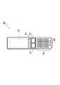
図60に示す変形例のリモコン300の特徴は、通常のものに比べてユーザーが操作するボタンの数を大幅に減らしている点にある。詳細は、後述するが、リモコン300は扉を持たない。ユーザーが操作するボタンは、図60に示すボタンのみである。
A feature of the
図60に示す変形例のリモコン300は、図示しない空気調和機が停止中のため、リモコン本体310(遠隔制御装置本体)の前面上部のインターフェイス表示部301に、時刻のみが表示されている。
60, since the air conditioner (not shown) is stopped, only the time is displayed on the
インターフェイス表示部301には、例えば、フルドット(255*160)LCD(液晶ディスプレイ)を用いている。
For the
従来のリモコンのインターフェイス表示部に用いているセグメント表示の表示制約(※決められた領域にて決められた内容でしか表示することができない機能制限)をなくし、インターフェイス画面内で自由な表現とアニメーションを展開することが可能となっている。 Eliminate the display restrictions on the segment display used in the interface display section of the conventional remote control (* function restrictions that can only be displayed with the contents determined in the determined area), and free expression and animation within the interface screen Can be deployed.
図51に示すリモコン200の設定情報表示部230は、セグメント表示のもので、決められた領域にて決められた内容でしか表示することができない。
The setting
インターフェイス表示部301の下方で、リモコン300の略中央部に、運転入/切ボタン302と、運転モード切換ボタン303とが配置されている。
Below the
運転モード切換ボタン303は、冷房ボタンと、除湿切換ボタンと、暖房ボタンとで構成される。
The operation
運転モード切換ボタン303の下方に、シーンボタン304と、しつど調節ボタン305と、温度調節ボタン306とが、一つの円の中に配置されている。
Below the operation
シーンボタン304は、シーンセレクトボタン304aと、上下ボタン304bと、決定ボタン304cとで構成される。
The
上下ボタン304bは、大きい円の中の中央部に配置され、円形状をなしている。上下ボタン304bは、一つのもので、ユーザーが上下ボタン304bの「▲」部分を押すことにより、インターフェイス表示部301のカーソル(図61参照)が上方向に移動する。
The up / down
ユーザーが上下ボタン304bの「▲」部分を一回押すと、インターフェイス表示部301のカーソルは、一行上に移動する。
When the user presses the “▲” portion of the up / down
ユーザーが上下ボタン304bの「▼」部分を押すことにより、インターフェイス表示部301のカーソル(図61参照)が下方向に移動する。
When the user presses the “▼” portion of the up / down
ユーザーが上下ボタン304bの「▼」部分を一回押すと、インターフェイス表示部301のカーソルは、一行下に移動する。
When the user presses the “▼” portion of the up / down
シーンセレクトボタン304aと、しつど調節ボタン305と、決定ボタン304cと、温度調節ボタン306とが、ドーナッツ状に配置されている。
A scene select button 304a, an
シーンボタン304の下に、戻るボタン307及びおしらせナビボタン308が、設けられている。戻るボタン307は、後述するが、例えば、設定終了などの機能を有する。
Below the
上記のレイアウトは、一例であって、図60の配置に限定されるものではない。 The above layout is an example and is not limited to the arrangement shown in FIG.
リモコン300の使用方法について説明する。空気調和機100が停止している状態から、空気調和機100の運転を開始する場合、運転入/切ボタン302、もしくは運転モード切換ボタン303の冷房ボタンと、除湿切換ボタンと、暖房ボタンのいずれかを押すことで、空気調和機100は運転を開始する。
A method of using the
冷房運転を行いたいときは、運転入/切ボタン302、もしくは運転モード切換ボタン303の冷房ボタンを押す。運転入/切ボタン302を押す場合は、前回の運転モードになる。例えば、前回が冷房であれば、今回も冷房になる。前回の運転モードと異なる運転モードにしたい場合は、その運転モードのボタンをもう一度押す。例えば、前回が除湿運転で、今回冷房運転を行いたいときは、運転入/切ボタン302を押すと除湿運転が開始するが、運転モード切換ボタン303の冷房ボタンを押すことで冷房運転が開始される。
When the cooling operation is desired, the operation on / off
空気調和機100が停止している状態から、運転入/切ボタン302、もしくは運転モード切換ボタン303の冷房ボタンと、除湿切換ボタンと、暖房ボタンのいずれかを押すことで、空気調和機100は運転を開始するが、このとき、リモコン300のインターフェイス表示部301には、シーンセレクト画面が表示される(図61参照)。
When the
詳細は後述するが、ユーザーがシーンセレクト選択実施後、所定時間経過すると、リモコン300のインターフェイス表示部301は通常画面(温度、湿度などの設定画面、図64参照)に切換わる。
Although details will be described later, when a predetermined time elapses after the user selects the scene selection, the
リモコン300のインターフェイス表示部301が通常画面で、且つシーン未設定時に、シーンセレクト画面を表示させるには、シーンボタン304のシーンセレクトボタン304aを押すと、インターフェイス表示部301はシーンセレクト画面になる。
To display the scene select screen when the
次に、シーンセレクトの内容の一例について説明する。インターフェイス表示部301に、生活シーンにあった最適なユーザーの気持ち(そのときに設定したい内容)を表示する。シーンセレクトの入力内容は、例えば、以下に示すとおりである。
(1)急いで冷やしたい(急いで暖めたい);
(2)風にあたりたくない(風にあたりたい);
(3)空気をきれいにしたい;
(4)部屋干ししたい;
(5)お肌をケアしたい;
(6)お客様をもてなしたい;
(7)快適に寝たい。
Next, an example of the contents of the scene select will be described. The
(1) I want to hurry and cool (I want to hurry and warm);
(2) I do not want to hit the wind (I want to hit the wind);
(3) I want to clean the air;
(4) I want to dry the room;
(5) I want to care for my skin;
(6) I want to treat customers;
(7) I want to sleep comfortably.
空気調和機100の運転開始時、もしくは空気調和機100の運転中にシーン設定のために、ユーザーがシーンボタン304のシーンセレクトボタン304aを押すと、リモコン300のインターフェイス表示部301は、例えば、図61に示すようなシーンセレクト画面(メニュー画面)になる。カーソルは、一番上の「急いで冷やしたい」にある。
When the user presses the scene select button 304a of the
ユーザーが選びたい入力内容にカーソルを移動するには、シーンボタン304の上下ボタン304bにより行う。例えば、「空気をキレイにしたい」を選ぶときは、図61の状態から、上下ボタン304bの「▼」部分を二回押すと、図62に示すように、カーソルは「空気をキレイにしたい」に移動する。
To move the cursor to the input content that the user wants to select, the up / down
また、「お客様をもてなしたい」を選ぶときは、図61の状態から、上下ボタン304bの「▼」部分を五回押すと、図63に示すように、カーソルは「お客様をもてなしたい」に移動する。
In addition, when selecting “I want to entertain the customer”, when the “▼” portion of the up / down
以下、図65、図66を参照しながら、シーンセレクト画面(メニュー画面)における入力内容の選択、選択されたシーンの内容、及びシーン詳細設定の流れを説明する。 Hereinafter, the selection of input contents on the scene selection screen (menu screen), the contents of the selected scene, and the flow of detailed scene settings will be described with reference to FIGS.
先ず、空気調和機100の運転開始時、もしくは空気調和機100の運転中にシーン設定のために、シーンボタン304のシーンセレクトボタン304aを押すと、リモコン300のインターフェイス表示部301は、例えば、図65(a)に示すようなシーンセレクト画面(メニュー画面)になる。カーソルは、一番上の「急いで冷やしたい」にある。
First, when the scene selection button 304a of the
次いで、シーンボタン304の上下ボタン304bの「▼」部分をユーザーが一回押すと図65(b)に示すように、カーソルが「風にあたりたくない」に移動する。
Next, when the user presses the “▼” portion of the up / down
ユーザーの設定したい内容は、「風にあたりたくない」ではなく、「お客様をもてなしたい」とする。そのため、ユーザーは、図65(c)に示すように、さらにシーンボタン304の上下ボタン304bの「▼」部分を四回押してカーソルを「お客様をもてなしたい」に移動させる。
The content that the user wants to set is not "I don't want to hit the wind" but "I want to entertain customers". Therefore, as shown in FIG. 65C, the user further presses the “▼” portion of the up / down
カーソルが「お客様をもてなしたい」にある状態で、シーンボタン304の決定ボタン304cを押す。すると、リモコン300のインターフェイス表示部301には、図66(a)に示すように、シーン内容が表示される。
In the state where the cursor is “I want to entertain the customer”, the
ここでは、例えば、「お客様をもてなしたい」の内容として、上から順に、「ハイパワー 30分」、「風 上向き」、「白金ナノコロイド」が表示される。
Here, for example, “
ここで、シーン内容がこのままでよければ、戻るボタン307を押してシーン終了となる。シーン終了後、所定時間経過すると、リモコン300のインターフェイス表示部301は、通常画面(温度、湿度などの設定画面)に変わる(図64参照)。
Here, if the scene content is acceptable, the
また、シーン内容の、例えば、「風 上向き」を切に変更したい場合は、ユーザーはシーンボタン304の決定ボタン304cを押す。すると、リモコン300のインターフェイス表示部1は、図66(e)のようなシーン詳細設定画面になる。
In addition, when the user wants to change the scene content to, for example, “upward”, the user presses the
シーン詳細設定画面は、例えば、上から、「お客様をもてなしたい 切 入」、「ハイパワー 30分 切 入 時間変更」、「風 上向き 切 入 調整」、「白金ナノコロイド 切 入」が表示される。尚、図66(e)の入がオンの表示は、入を四角で囲って表示しているが、ここでは下線で示している。
Scene Details setting screen, for example, from the top, is displayed "OFF ON you want to entertain customers", "Change
図66(e)のシーン詳細設定画面での左端の三角のカーソルは、「ハイパワー 30分 切 入 時間変更」にある。
The left edge of the triangle of the cursor at the scene detailed setting screen in FIG. 66 (e) is to "change the high-
ここで、ユーザーが、「風 上向き」を切に設定変更したいとする。 Here, it is assumed that the user wants to change the setting to “windward”.
そこで、ユーザーは、シーンボタン304の上下ボタン304bの「▼」部分を一回押して三角のカーソルを、「風 上向き 切 入 調整」に移動する。
Thus, the user, the cursor of the "▼" portion by pressing one of the triangle up and down
そして、ユーザーは、決定ボタン4cを二回押して「風 上向き 切 入 調整」に設定を変更する(図66(f))。 Then, the user, and press the enter button 4c twice to change the setting to "wind up Off On Adjustment" (FIG. 66 (f)).
さらに、ユーザーは、戻るボタン307を押して設定を終了する。すると、図66(g)に示すように、リモコン300のインターフェイス表示部301には、「お客様をもてなしたい」の内容として、上から順に、「ハイパワー 30分」、「白金ナノコロイド」が表示される。
Further, the user presses the
その後、所定時間が経過すると、リモコン300のインターフェイス表示部301は、通常画面(温度、湿度などの設定画面)に切換わる(図64参照)。
Thereafter, when a predetermined time elapses, the
図65(a)〜図65(c)のシーンセレクト画面(メニュー画面)について、補足する。例えば、図65(a)〜図65(c)では、リモコン300のインターフェイス表示部301の大部分は、シーンセレクト画面(メニュー画面)に使用されるが、インターフェイス表示部301の下部には、シーンセレクトの入力内容とともに、選択されている(カーソルがある)シーンに対応したアニメーションが夫々の図に示すように表示される。
The scene selection screen (menu screen) in FIGS. 65A to 65C will be supplemented. For example, in FIGS. 65A to 65C, most of the
図65(a)に示すようなカーソルが一番上の「急いで冷やしたい」にあるときは、同図に示されているように、人が太陽の光を浴びて汗をかいているアニメーションが、インターフェイス表示部301の下部に表示される。
When the cursor as shown in FIG. 65 (a) is at the top "I want to cool it down quickly", as shown in the figure, an animation in which a person is sweating in the sunlight. Is displayed at the bottom of the
図65(b)に示すようなカーソルが「風にあたりたくない」にあるときは、同図に示されているように、空気調和機からの調和空気が、人を避けて吹き分けられているアニメーションが、インターフェイス表示部301の下部に表示される。
When the cursor as shown in FIG. 65 (b) is in "I do not want to hit the wind", as shown in the figure, the conditioned air from the air conditioner is blown away avoiding people. The animation is displayed at the bottom of the
図65(c)に示すようなカーソルが「お客様をもてなしたい」にあるときは、同図に示されているように、人(客)が家に近づいているアニメーションが、インターフェイス表示部301の下部に表示される。
When the cursor as shown in FIG. 65 (c) is in “I want to entertain a customer”, as shown in FIG. 65, an animation of a person (customer) approaching the house is displayed on the
尚、図65(a)〜図65(c)の各アニメーションは、同じものが表示されるのではなく、刻々と変化していく。図65(a)〜図65(c)では、その中の一画面を表示している。 Note that the animations shown in FIGS. 65 (a) to 65 (c) are not displayed in the same manner, but change every moment. In FIG. 65 (a) to FIG. 65 (c), one screen is displayed.
図65(a)〜図65(c)のシーンセレクト画面(メニュー画面)でのアニメーションの表示方法には、二通りある。一つは、図65(a)〜図65(c)に示すように、シーンセレクト画面(メニュー画面)の下にアニメーションを表示する方法である。 There are two methods for displaying animation on the scene selection screen (menu screen) shown in FIGS. 65 (a) to 65 (c). One is a method of displaying an animation under the scene selection screen (menu screen) as shown in FIGS. 65 (a) to 65 (c).
他の一つは、最初はシーンセレクト画面のみが表示され、所定時間経過後(例えば、数秒後)にアニメーションが、リモコン300のインターフェイス表示部301の全画面に表示される。これにより、ユーザーはそのシーンの内容をよく理解できる。その後、アニメーション表示中の適当な時期に、ユーザーが決定ボタン304cを押すと、図66(d)のシーン内容に移行する。
The other one is that only the scene selection screen is initially displayed, and an animation is displayed on the entire screen of the
次に、刻々と変化していくアニメーションの一例を示す。図67は、シーンセレクトが「空気をキレイにしたい」のときの、アニメーションの一例である。リモコン300のインターフェイス表示部301の最上部に、「白金ナノコロイド放出中」が表示される。アニメーションは、矢印の順に変化していく。図中、小さい円形、ひし形のものが、白金ナノコロイドである。白金ナノコロイドにより、空気中のウイルスが消滅もしくは小さくなっていくことがわかる。
Next, an example of an animation that changes every moment is shown. FIG. 67 is an example of an animation when the scene select is “I want to clean the air”. “Platinum nano colloid is being released” is displayed at the top of the
図67に示すシーンセレクトが「空気をキレイにしたい」のときのアニメーションが、シーンセレクト画面で、「空気をキレイにしたい」にカーソルがきたときに、シーンセレクト画面の下、もしくはインターフェイス表示部301の全画面に表示される。
67. When the scene selection shown in FIG. 67 is “I want to clean the air” and the cursor comes to “I want to clean the air” on the scene selection screen, the animation is displayed below the scene selection screen or the
このように、空気をキレイにする方法として、空気中のウイルスを除去する機能をもつデバイスを運転させますといったことを、「白金ナノコロイドを放出中」という言葉による説明と、その機能内容をイメージさせるアニメーションを表示することを特徴としている。 In this way, as a method of cleansing air, operating a device that has the function of removing viruses in the air is explained by the word “emitting platinum nanocolloid” and its functional image The animation is displayed.
空気中のウイルスを白金ナノコロイドにて除菌していく旨の内容をアニメーションにて表示することで、ユーザーに機能の内容をわかりやすく伝えることができる。それにより、空気調和機の持つ機能をユーザーが十二分に使いこなさせることで、より省エネな運転の励行をユーザーに実施させることができる。 By displaying the contents of the effect of sterilizing viruses in the air with platinum nanocolloids in an animation, the contents of the functions can be communicated to the user in an easy-to-understand manner. As a result, the user can fully implement the functions of the air conditioner so that the user can carry out more energy-saving driving.
図68は、シーンセレクトが「お肌をケアしたい」のときの、アニメーションの一例である。リモコン300のインターフェイス表示部301の最上部に、「白金ナノコロイド放出中」が表示される。アニメーションは、矢印の順に変化していく。図中、小さい円形のものが、白金ナノコロイドである。白金ナノコロイドにより、人の顔に白金ナノコロイドが作用して、肌がうるおされることがわかる。
FIG. 68 shows an example of an animation when the scene select is “I want to care for my skin”. “Platinum nano colloid is being released” is displayed at the top of the
図69はシーンセレクトの内容を複数選択したときのシーンセレクト選択画面を拡大したものである。このように、二つ(複数)のシーンセレクトを選択することができる。これによって、ユーザーが、一つのシーンセレクトの選択で気持ちを満足することができない場合など、さまざま条件・気持ちに対応することできることを特徴としている。 FIG. 69 is an enlarged view of the scene select selection screen when a plurality of scene select contents are selected. In this way, two (plural) scene selections can be selected. This is characterized in that the user can respond to various conditions and feelings such as when the user cannot satisfy the feeling by selecting one scene select.
図69の例は、「急いで冷やしたい」、且つ「空気をキレイにしたい」の二つのシーンセレクトを選択している。二つ以上の複数のシーンセレクトの選択も可能である。 In the example of FIG. 69, two scene selections of “I want to cool quickly and want to cool” and “I want to clean the air” are selected. Two or more scene select selections are also possible.
また、シーンセレクトの表示優先順番は、ユーザーの使用選択頻度により次回の選択画面から表示内容の順番を変更することを特徴とし、使用頻度の高いものから、インターフェイス表示部301の最上部から順に表示する。
Further, the display priority order of scene selection is characterized in that the order of display contents is changed from the next selection screen according to the use selection frequency of the user, and is displayed in order from the top of the
また、複数選択の頻度、シーンセレクトの組み合わせを学習することでシーンセレクトの入力内容を変更していくことも特徴としている。 Another feature is that the input content of the scene select is changed by learning the frequency of multiple selection and the combination of scene select.
例えば、「急いで冷やしたい」と「空気をキレイにしたい」とのシーンセレクト複数選択の頻度が多い場合は、「急いで冷やし、空気をキレイにしたい」のように組み合わせたシーンセレクトを新たに表示する(図70参照)。 For example, if you frequently select multiple scene selections, such as `` I want to cool quickly '' and `` I want to clean the air '', I will add a new scene select that combines `` I want to cool quickly and clean the air '' Display (see FIG. 70).
このように、ユーザーの使い勝手にあった、生活にあったシーンセレクトを提供することを特徴としている。 In this way, it is characterized by providing a scene select suitable for the user and suitable for life.
また、リモコン300のインターフェイス表示部301にて製品機能を表示して説明することで、製品に付帯している空気調和機の取扱説明書のもつ機能を一部肩代わりすることを特徴としている。
Further, by displaying and explaining the product function on the
本実施の形態の特徴を明白にするために、一般的な空気調和機のリモコン400について、簡単に述べる。
In order to clarify the characteristics of the present embodiment, a general air conditioner
図76乃至図79を参照しながら、一般的な空気調和機のリモコン400について説明する。
A general air conditioner
図76乃至図79に示す一般的な空気調和機のリモコン400は、縦長なスティックタイプのものである。
A general air conditioner
リモコン400は、冷房、除湿、暖房などの運転モード、設定温度、設定湿度、風速、風向など空気調和機の運転状態を表示する表示部402が設けられている。
The
表示部402の下に、空気調和機の運転・停止を行う入/切ボタン403が設けられている。
An on / off
入/切ボタン403の下に、温度の調節を行う温度調節ボタン407と湿度の調節を行う湿度調節ボタン404とが左右に並べて配置されている。
Below the ON /
リモコン400は、温度の調節を行う温度調節ボタン407と湿度の調節を行う湿度調節ボタン404の下に、リモコン扉415を備える。リモコン扉415は下方に開く(図77参照)。
The
リモコン扉415の表面に、リモコン扉415が閉じた状態で操作が可能となるボタンが設けられている。図78に示すように、リモコン扉415の表面の上部に、冷房ボタン412、除湿切換ボタン411、暖房ボタン410が左右に並べて配置されている。
On the surface of the
リモコン扉415の表面の略中央部に、空気調和機の情報を要求する、おしらせナビボタン413が設けられている。
A
おしらせナビボタン413の下で、リモコン扉415の表面の下部に、送風ボタン414、入タイマーボタン416、切タイマーボタン417が左右に並べて配置されている。
Under the
温度調節ボタン407及び湿度調節ボタン404の下に、リモコン扉415が開いたときに現れる詳細設定ボタン群405が設けられている(図79参照)。詳細設定ボタン群405は、例えば、室内機から吹き出される風速及び風向、タイマーなどの詳細設定を行うときに使用される。
Below the
詳細設定ボタン群405の最下部の中央に、リモコン扉415の開閉を検知する扉開閉検知スイッチ406が設けられている。
A door opening /
リモコン扉415の裏側に、リモコン扉415を閉めたときに扉開閉検知スイッチ406を押圧して、オフからオンにする突起(図示せず)が形成されている。
A protrusion (not shown) is formed on the back side of the
このように、一般的な空気調和機のリモコン400は、リモコン400の表面、リモコン扉415に多くのボタンがある。そのため、日常以外の生活シーンにおける適切なリモコン設定がわからないといった不安や、普段使わない機能はいざというときに使い方がわからず最後はあきらめてしまうといったような、複雑な操作と印象を与えてしまっているといった課題を有している。また、新しい付加価値名称を記載してあるボタンであっても、そのボタンを押したときの効果・機能がわからないといった課題を有している。
Thus, the
変形例のリモコン300は、既に述べたように、操作ボタンの数を一般的なリモコン400に比べて、大幅に減らしている。また、一般的なリモコン400のようなリモコン扉415も持たない。
As already described, the
複数のボタンを操作する代わりに、シーンボタン304だけの操作により、リモコン300のインターフェイス表示部301に表示されるシーンセレクト(メニュー)を選択・決定することで様々な空気調和機100の制御が可能となる。
しかも、リモコン300のインターフェイス表示部301に表示されるシーンセレクト(メニュー)は、ユーザーの日常生活のシーンを言葉で表現するものであり、且つそのシーンをアニメーションで表示する。従って、ユーザーは、付加価値機能に迷うことなく、あきらめることなく空気調和機100の付加機能をフルに使うことができる。
In addition, the scene selection (menu) displayed on the
リモコン300のインターフェイス表示部301に表示されるシーンセレクト(メニュー)の数が多く、インターフェイス表示部301に一度に表示できない場合は、スクロールにより全シーンセレクトの選択・決定を可能とする。
When the number of scene selections (menus) displayed on the
リモコン300のインターフェイス表示部301に表示されるシーンセレクト(メニュー)と、一般的なリモコン400の各種ボタンとの関係について、若干触れる。
The relationship between the scene select (menu) displayed on the
例えば、シーンセレクトの「急いで冷やしたい」は、一般的なリモコン400の詳細設定ボタン群405の中の「ハイパワーボタン」(図示で特定していない)に相当する。
For example, “I want to chill quickly” in the scene select corresponds to a “high power button” (not specified in the drawing) in the detailed
また、シーンセレクトの「風にあたりたくない」は、一般的なリモコン400の詳細設定ボタン群205の中の「風あて/風よけボタン」(図示で特定していない)に相当する。
Also, “I do not want to hit the wind” in the scene select corresponds to a “wind / wind button” (not specified in the figure) in the detailed setting button group 205 of the general
また、シーンセレクトの「空気をキレイにしたい」は、一般的なリモコン400の「ミストボタン」(図示で特定していない)に相当する。
The scene select “I want to clean the air” corresponds to a “mist button” (not specified in the figure) of a general
また、シーンセレクトの「お肌をケアしたい」は、一般的なリモコン400の「ミストボタン」(図示で特定していない)に相当する。
Also, “I want to care for my skin” in the scene select corresponds to a “mist button” (not specified in the figure) of a general
また、シーンセレクトの「部屋干ししたい」は、一般的なリモコン400の「ランドリーボタン」(図示で特定していない)に相当する。
The scene selection “I want to dry the room” corresponds to a “laundry button” (not specified in the figure) of the general
また、シーンセレクトの「快適に寝たい」は、一般的なリモコン400の「ねむりボタン」(図示で特定していない)に相当する。
Also, “I want to sleep comfortably” in the scene select corresponds to a “sleep button” (not specified in the figure) of a general
このように、一般的なリモコン400の各種ボタンを、リモコン300のインターフェイス表示部301に表示されるシーンセレクトの入力内容に置き換えることができる。以上の説明では、一般的なリモコン400の一部のボタンと、リモコン300のインターフェイス表示部301に表示されるシーンセレクトの入力内容との関係を説明した。説明は省くが、一般的なリモコン400の全てのボタンを、リモコン300のインターフェイス表示部301に表示されるシーンセレクトに置き換えることができる。
As described above, various buttons of the general
このように、変形例のリモコン300は、一般的なリモコン400の数が多くて理解しにくいボタンを廃止して、インターフェイス表示部301に表示されるシーンセレクトに置き換え、シーンセレクトをユーザーの日常生活のシーンを言葉で表現し、且つそのシーンをアニメーションで表示するので、ボタン入力ではなく、ユーザーの日常生活のシーンを言葉で表現する入力にすることで、付加価値機能に迷うことなく、且つあきらめることなく空気調和機100の付加機能をフルに使うことができ、空気調和機100の省エネを容易に実現することを可能とする。
As described above, the
さらに、生活シーン入力にて選択したユーザーニーズを実現する空気調和機100の付加機能の効果を、言葉による表現とアニメーションにて表現することでベネフィットを容易に伝えることを可能とし、製品に付帯する取扱説明書をわざわざ見る手間と必要性をなくしたことを特徴とする。
Furthermore, it is possible to easily convey the benefits by expressing the effects of the additional functions of the
図58、図59に示した省エネアドバイスの内容を、フルドット(255*160)LCD(液晶ディスプレイ)を用いるインターフェイス表示部301(図60参照)を有する変形例のリモコン300(遠隔制御装置)のインターフェイス表示部301に一括表示させる表示例について、図71乃至図75を参照しながら説明する。
The content of the energy saving advice shown in FIGS. 58 and 59 is the same as that of the remote control 300 (remote control device) of the modification having the interface display unit 301 (see FIG. 60) using a full dot (255 * 160) LCD (liquid crystal display). Display examples to be collectively displayed on the
図58、図59において、リモコン200のガイダンス表示部220(変化に富んだ画像表示を行うために、各画素を格子状に均等配列したドットマトリクスタイプの液晶パネルを使用している)に表示される詳細な省エネ運転情報(おすすめ運転や省エネアドバイスに関する情報)は、ガイダンス表示部220の面積が小さいために一括して表示することができず、アドバイス内容の表示1、表示2、表示3を順番に所定の時間(例えば、5秒)表示するようにしている。
58 and 59, it is displayed on the
変形例のリモコン300(遠隔制御装置)のフルドット(255*160)LCD(液晶ディスプレイ)を用いるインターフェイス表示部301(図60参照)には、アドバイス内容の表示1、表示2、表示3(図58、図59参照)を一括して表示することが可能となる。
The interface display unit 301 (see FIG. 60) using the full-dot (255 * 160) LCD (liquid crystal display) of the remote controller 300 (remote control device) of the modified example has an
図59の赤外線センサ3より得られる省エネアドバイスの暖房運転時の詳細内容を、変形例のリモコン300のインターフェイス表示部301に一括表示する具体例を図71乃至図75に示す。
Specific examples in which the detailed contents during the heating operation of the energy saving advice obtained from the
図71は、図59のアドバイス概要が「ソフト省エネ効果を教える」である場合の、アドバイス内容を一括して、リモコン300のインターフェイス表示部301に表示している。
FIG. 71 shows the advice contents collectively in the
即ち、インターフェイス表示部301には、最上部に時刻が表示され、その下に運転モード(ここでは、暖房)、設定温度(20.5℃)、設定湿度(50%)が表示される。そして、それらの下に、「おしらせナビ」として、“空気温度のみで制御しています”、“体感で体に感じる温度で運転”、
“体感温度? はい:“エコ”押す いいえ:放置”が一括表示される。これにより、ユーザーは一度にアドバイス内容の全体を見ることができる。
That is, on the
“Experience temperature? Yes: Press“ Eco ”No: Leave” is displayed at once. Thereby, the user can see the whole advice content at once.
図72は、図59のアドバイス概要が「人の動きを検知し、滞留が一定時間を超えている場合は、人が集まった方が省エネ運転が可能な事を教える」である場合の、アドバイス内容を一括して、リモコン300のインターフェイス表示部301に表示している。
FIG. 72 shows an advice when the advice outline of FIG. 59 is “detection of a person's movement and if the stay has exceeded a certain period of time, teach that people gathered can save energy”. The contents are collectively displayed on the
即ち、インターフェイス表示部301には、最上部に時刻が表示され、その下に運転モード(ここでは、暖房)、設定温度(20.5℃)、設定湿度(50%)が表示される。そして、それらの下に、「おしらせナビ」として、“お部屋全体を空調しています”、“風よけで省エネになります”、
“風よけ設定? はい:“エコ”押す いいえ:放置”が一括表示される。これにより、ユーザーは一度にアドバイス内容の全体を見ることができる。
That is, on the
“Windproof setting? Yes: Press“ Eco ”No: Leave” is displayed at once. Thereby, the user can see the whole advice content at once.
図73は、図59のアドバイス概要が「赤外線センサでの夏の日射、冬の低い輻射でドア/カーテンの開閉を確認し閉めることをすすめる」である場合の、アドバイス内容を一括して、リモコン300のインターフェイス表示部301に表示している。
FIG. 73 shows a summary of advice in the case where the advice outline in FIG. 59 is “recommend closing / opening of door / curtain with infrared radiation in summer and low radiation in winter”. The information is displayed on the
即ち、インターフェイス表示部301には、最上部に時刻が表示され、その下に運転モード(ここでは、暖房)、設定温度(20.5℃)、設定湿度(50%)が表示される。そして、それらの下に、「おしらせナビ」として、“壁面に冷たい場所があります”、“カーテン・ドアを閉めると”、“省エネになります?”が一括表示される。これにより、ユーザーは一度にアドバイス内容の全体を見ることができる。
That is, on the
図74は、図59のアドバイス概要が「足元が寒いユーザーに対してのワンポイントアドバイス」である場合の、アドバイス内容を一括して、リモコン300のインターフェイス表示部301に表示している。
FIG. 74 shows advice contents collectively in the
即ち、インターフェイス表示部301には、最上部に時刻が表示され、その下に運転モード(ここでは、暖房)、設定温度(20.5℃)、設定湿度(50%)が表示される。そして、それらの下に、「おしらせナビ」として、“風向が上向です 足元寒くない?”、“風速自動で省エネになります”、“風向自動に設定? はい:“エコ”押す いいえ:放置”が一括表示される。これにより、ユーザーは一度にアドバイス内容の全体を見ることができる。
That is, on the
図75は、図59のアドバイス概要が「活動量を検知したときのアドバイス」である場合の、アドバイス内容を一括して、リモコン300のインターフェイス表示部301に表示している。
FIG. 75 shows the contents of advice in a batch on the
即ち、インターフェイス表示部301には、最上部に時刻が表示され、その下に運転モード(ここでは、暖房)、設定温度(20.5℃)、設定湿度(50%)が表示される。そして、それらの下に、「おしらせナビ」として、“空気が汚れやすい状態です?”、“ミストで浮遊菌を抑制します”、“ミスト設定? はい:“エコ”押す いいえ:放置”が一括表示される。これにより、ユーザーは一度にアドバイス内容の全体を見ることができる。
That is, on the
1 金属缶、2 配光視野角、3 赤外線センサ、5 筐体、6 ステッピングモーター、7 取付部、12 主婦、13 幼児、14 窓、16 左壁面、17 右壁面、18 床面、19 正面壁、20 ECOランプ、31 窓領域、40 室内機筺体、41 吸込口、42 吹出口、43 上下フラップ、44 左右フラップ、45 送風機、46 熱交換器、51 赤外線センサ駆動部、52 赤外線画像取得部、53 温度ムラ境界検知部、54 基準壁位置算出部、55 床面座標変換部、56 正面左右壁位置算出部、57 検知履歴蓄積部、58 壁位置判断部、60 境界線、61 人体検出部、62 人体位置履歴蓄積部、63 人体位置有効性判定部、64 温度ムラ有効性判定部、66 領域、100 空気調和機、100a 表示部、101 熱画像取得部、102 床壁検知部、103 室温判定部、104 外気温判定部、105 壁領域内温度差判定部、106 壁領域内外気温度領域抽出部、107 窓領域抽出部、108 窓領域内温度差判定部、109 カーテン閉め動作判定部、110 ユーザーインターフェイス部、120 左壁面境界線、121 右壁面境界線、122 正面壁境界線、200 リモコン、210 ECOアドバイスボタン、220 ガイダンス表示部、230 設定情報表示部、240 入/切ボタン、250 温度調節ボタン、260 湿度調節ボタン、270 運転モード変更ボタン、280 タイマーボタン、290 ミストボタン、300 リモコン、301 インターフェイス表示部、302 運転入/切ボタン、303 運転モード切換ボタン、304 シーンボタン、304a シーンセレクトボタン、304b 上下ボタン、304c 決定ボタン、305 しつど調節ボタン、306 温度調節ボタン、310 リモコン本体、307 戻るボタン、308 おしらせナビボタン、400 リモコン、402 表示部、403 入/切ボタン、404 湿度調節ボタン、405 詳細設定ボタン、406 扉開閉検知スイッチ、407 温度調節ボタン、410 暖房ボタン、412 冷房ボタン、411 除湿切換ボタン、413 おしらせナビボタン、414 送風ボタン、415 リモコン扉、416 入タイマーボタン、417 切タイマーボタン。 DESCRIPTION OF SYMBOLS 1 Metal can, 2 Light distribution viewing angle, 3 Infrared sensor, 5 Case, 6 Stepping motor, 7 Mounting part, 12 Housewife, 13 Infant, 14 Window, 16 Left wall surface, 17 Right wall surface, 18 Floor surface, 19 Front wall , 20 ECO lamp, 31 window region, 40 indoor unit housing, 41 suction port, 42 air outlet, 43 top and bottom flaps, 44 left and right flaps, 45 blower, 46 heat exchanger, 51 infrared sensor drive unit, 52 infrared image acquisition unit, 53 temperature unevenness boundary detection unit, 54 reference wall position calculation unit, 55 floor surface coordinate conversion unit, 56 front left and right wall position calculation unit, 57 detection history storage unit, 58 wall position determination unit, 60 boundary line, 61 human body detection unit, 62 human body position history accumulating section, 63 human body position validity determining section, 64 temperature unevenness validity determining section, 66 area, 100 air conditioner, 100a display section, 10 DESCRIPTION OF SYMBOLS 1 Thermal image acquisition part, 102 Floor wall detection part, 103 Room temperature determination part, 104 Outside air temperature determination part, 105 Wall area inside temperature difference determination part, 106 Wall area inside / outside air temperature area extraction part, 107 Window area extraction part, 108 Window In-region temperature difference determination unit, 109 curtain closing operation determination unit, 110 user interface unit, 120 left wall boundary line, 121 right wall boundary line, 122 front wall boundary line, 200 remote control, 210 ECO advice button, 220 guidance display unit, 230 Setting information display section, 240 On / off button, 250 Temperature adjustment button, 260 Humidity adjustment button, 270 Operation mode change button, 280 Timer button, 290 Mist button, 300 Remote control, 301 Interface display section, 302 Operation on / off button , 303 Operation mode switching button, 04 Scene button, 304a Scene select button, 304b Up / down button, 304c Enter button, 305 Incremental adjustment button, 306 Temperature adjustment button, 310 Remote control body, 307 Return button, 308 INFORMATION NAVI button, 400 Remote control, 402 display, 403 ON / OFF button, 404 Humidity adjustment button, 405 Detailed setting button, 406 Door open / close detection switch, 407 Temperature adjustment button, 410 Heating button, 412 Cooling button, 411 Dehumidification switching button, 413 News navigation button, 414 Air blow button, 415 Remote control door 416 On timer button, 417 off timer button.
Claims (4)
前記本体の前面に所定の俯角で下向きに取り付けられ、温度検出対象範囲を左右に走査して温度検出対象の温度を検出する赤外線センサと、
前記赤外線センサにより人や発熱機器の存在を検知して、当該空気調和機の運転を制御する制御部と、
遠隔制御装置本体と、前記遠隔制御装置本体に設けられ、フルドットの液晶ディスプレイで構成されるインターフェイス表示部と、前記遠隔制御装置本体に設けられる情報要求ボタンと、を有し、ユーザーが当該空気調和機の運転を制御する遠隔制御装置と、
前記制御部と前記遠隔制御装置との間で双方向通信を行う通信部と、を備え、
前記ユーザーが前記情報要求ボタンを押すことにより、前記制御部が有する省エネアドバイスの内容が、前記通信部を介して前記インターフェイス表示部に一括表示されることを特徴とする空気調和機。 A substantially box-shaped body having a suction port for sucking air in the room and a blow-out port for blowing out conditioned air;
An infrared sensor that is attached downward to the front surface of the main body at a predetermined depression angle and that detects the temperature of the temperature detection target by scanning the temperature detection target range from side to side;
A control unit that detects the presence of a person or a heat generating device by the infrared sensor and controls the operation of the air conditioner;
A remote control device main body, an interface display unit provided on the remote control device main body and configured by a full-dot liquid crystal display, and an information request button provided on the remote control device main body, and the user A remote control device for controlling the operation of the harmonic machine;
A communication unit that performs bidirectional communication between the control unit and the remote control device,
The air conditioner characterized in that when the user presses the information request button, the content of the energy saving advice of the control unit is collectively displayed on the interface display unit via the communication unit.
Priority Applications (1)
| Application Number | Priority Date | Filing Date | Title |
|---|---|---|---|
| JP2009273472A JP2011117627A (en) | 2009-12-01 | 2009-12-01 | Air conditioner |
Applications Claiming Priority (1)
| Application Number | Priority Date | Filing Date | Title |
|---|---|---|---|
| JP2009273472A JP2011117627A (en) | 2009-12-01 | 2009-12-01 | Air conditioner |
Publications (2)
| Publication Number | Publication Date |
|---|---|
| JP2011117627A true JP2011117627A (en) | 2011-06-16 |
| JP2011117627A5 JP2011117627A5 (en) | 2012-11-08 |
Family
ID=44283161
Family Applications (1)
| Application Number | Title | Priority Date | Filing Date |
|---|---|---|---|
| JP2009273472A Pending JP2011117627A (en) | 2009-12-01 | 2009-12-01 | Air conditioner |
Country Status (1)
| Country | Link |
|---|---|
| JP (1) | JP2011117627A (en) |
Cited By (3)
| Publication number | Priority date | Publication date | Assignee | Title |
|---|---|---|---|---|
| JP2017108259A (en) * | 2015-12-09 | 2017-06-15 | 三菱電機株式会社 | Appliance control system and appliance control method |
| EP2733430A3 (en) * | 2012-11-16 | 2018-03-21 | Mitsubishi Electric Corporation | Indoor unit of air-conditioning apparatus |
| JPWO2021064850A1 (en) * | 2019-10-01 | 2021-04-08 |
Citations (18)
| Publication number | Priority date | Publication date | Assignee | Title |
|---|---|---|---|---|
| JPH05149791A (en) * | 1991-11-29 | 1993-06-15 | Matsushita Electric Ind Co Ltd | Room information detecting device |
| JPH06180139A (en) * | 1992-12-11 | 1994-06-28 | Matsushita Electric Ind Co Ltd | Application devices of control device and image processing device of air-conditioner |
| JPH07103551A (en) * | 1993-10-08 | 1995-04-18 | Mitsubishi Electric Corp | Controller for air-conditioner |
| JPH0729935U (en) * | 1993-11-08 | 1995-06-02 | クラリオン株式会社 | FM multiplex broadcast receiver |
| JPH10126285A (en) * | 1996-10-22 | 1998-05-15 | Sharp Corp | Fm multiplex broadcast receiver |
| JPH11257717A (en) * | 1998-03-12 | 1999-09-24 | Toshiba Corp | Air-conditioning equipment |
| JP2002022250A (en) * | 2000-07-05 | 2002-01-23 | Mitsubishi Heavy Ind Ltd | Wireless remote control unit for air conditioner |
| JP2002147820A (en) * | 2000-08-30 | 2002-05-22 | Mitsubishi Electric Corp | Air conditioner |
| JP2002206791A (en) * | 2001-01-12 | 2002-07-26 | Matsushita Electric Ind Co Ltd | Remote controller for air conditioner |
| JP2002295940A (en) * | 2001-03-30 | 2002-10-09 | Sanyo Electric Co Ltd | Remote monitoring system of apparatus in shop |
| JP2006352805A (en) * | 2005-06-20 | 2006-12-28 | Matsushita Electric Works Ltd | House control and monitoring system, and house control and monitoring apparatus |
| JP2007120089A (en) * | 2005-10-26 | 2007-05-17 | Matsushita Electric Works Ltd | Solar radiation shading control device |
| JP2008261630A (en) * | 2007-01-17 | 2008-10-30 | Daikin Ind Ltd | Air conditioner |
| JP2009092282A (en) * | 2007-10-05 | 2009-04-30 | Mitsubishi Electric Corp | Air conditioner |
| JP2009139010A (en) * | 2007-12-06 | 2009-06-25 | Sharp Corp | Air conditioner |
| JP2009144435A (en) * | 2007-12-14 | 2009-07-02 | Mitsubishi Electric Building Techno Service Co Ltd | Opening and closing window system interlocked with air conditioner |
| JP2009192132A (en) * | 2008-02-14 | 2009-08-27 | Panasonic Corp | Air conditioner |
| JP2009264631A (en) * | 2008-04-23 | 2009-11-12 | Daikin Ind Ltd | Air conditioner |
-
2009
- 2009-12-01 JP JP2009273472A patent/JP2011117627A/en active Pending
Patent Citations (18)
| Publication number | Priority date | Publication date | Assignee | Title |
|---|---|---|---|---|
| JPH05149791A (en) * | 1991-11-29 | 1993-06-15 | Matsushita Electric Ind Co Ltd | Room information detecting device |
| JPH06180139A (en) * | 1992-12-11 | 1994-06-28 | Matsushita Electric Ind Co Ltd | Application devices of control device and image processing device of air-conditioner |
| JPH07103551A (en) * | 1993-10-08 | 1995-04-18 | Mitsubishi Electric Corp | Controller for air-conditioner |
| JPH0729935U (en) * | 1993-11-08 | 1995-06-02 | クラリオン株式会社 | FM multiplex broadcast receiver |
| JPH10126285A (en) * | 1996-10-22 | 1998-05-15 | Sharp Corp | Fm multiplex broadcast receiver |
| JPH11257717A (en) * | 1998-03-12 | 1999-09-24 | Toshiba Corp | Air-conditioning equipment |
| JP2002022250A (en) * | 2000-07-05 | 2002-01-23 | Mitsubishi Heavy Ind Ltd | Wireless remote control unit for air conditioner |
| JP2002147820A (en) * | 2000-08-30 | 2002-05-22 | Mitsubishi Electric Corp | Air conditioner |
| JP2002206791A (en) * | 2001-01-12 | 2002-07-26 | Matsushita Electric Ind Co Ltd | Remote controller for air conditioner |
| JP2002295940A (en) * | 2001-03-30 | 2002-10-09 | Sanyo Electric Co Ltd | Remote monitoring system of apparatus in shop |
| JP2006352805A (en) * | 2005-06-20 | 2006-12-28 | Matsushita Electric Works Ltd | House control and monitoring system, and house control and monitoring apparatus |
| JP2007120089A (en) * | 2005-10-26 | 2007-05-17 | Matsushita Electric Works Ltd | Solar radiation shading control device |
| JP2008261630A (en) * | 2007-01-17 | 2008-10-30 | Daikin Ind Ltd | Air conditioner |
| JP2009092282A (en) * | 2007-10-05 | 2009-04-30 | Mitsubishi Electric Corp | Air conditioner |
| JP2009139010A (en) * | 2007-12-06 | 2009-06-25 | Sharp Corp | Air conditioner |
| JP2009144435A (en) * | 2007-12-14 | 2009-07-02 | Mitsubishi Electric Building Techno Service Co Ltd | Opening and closing window system interlocked with air conditioner |
| JP2009192132A (en) * | 2008-02-14 | 2009-08-27 | Panasonic Corp | Air conditioner |
| JP2009264631A (en) * | 2008-04-23 | 2009-11-12 | Daikin Ind Ltd | Air conditioner |
Cited By (5)
| Publication number | Priority date | Publication date | Assignee | Title |
|---|---|---|---|---|
| EP2733430A3 (en) * | 2012-11-16 | 2018-03-21 | Mitsubishi Electric Corporation | Indoor unit of air-conditioning apparatus |
| JP2017108259A (en) * | 2015-12-09 | 2017-06-15 | 三菱電機株式会社 | Appliance control system and appliance control method |
| JPWO2021064850A1 (en) * | 2019-10-01 | 2021-04-08 | ||
| WO2021064850A1 (en) * | 2019-10-01 | 2021-04-08 | 三菱電機株式会社 | Control device, air-conditioning device, air-conditioning system and control method |
| JP7321283B2 (en) | 2019-10-01 | 2023-08-04 | 三菱電機株式会社 | Control devices, air conditioners and air conditioning systems |
Similar Documents
| Publication | Publication Date | Title |
|---|---|---|
| JP5258816B2 (en) | Air conditioner | |
| US11041645B2 (en) | Radiation receiving sensor and air conditioner, electronic cooker, and transport device including the same | |
| KR101291967B1 (en) | Air conditioner | |
| JP5800760B2 (en) | Air conditioner | |
| JP5489915B2 (en) | Air conditioner | |
| JP5216519B2 (en) | Air conditioner | |
| JP2010091253A (en) | Air conditioner | |
| JP5256074B2 (en) | Air conditioner | |
| JP2016061446A (en) | Air conditioner | |
| JP5317839B2 (en) | Air conditioner | |
| JP5422172B2 (en) | Air conditioner | |
| JP5247647B2 (en) | Air conditioner | |
| JP2011117627A (en) | Air conditioner | |
| JP5840589B2 (en) | Air conditioner | |
| JP6105695B2 (en) | Air conditioner | |
| JP5289518B2 (en) | Air conditioner and radiation temperature calculation method | |
| JP5575317B2 (en) | Air conditioner | |
| JP5795099B2 (en) | Air conditioner | |
| JP5404902B2 (en) | Air conditioner | |
| JP2013036736A (en) | Remote controller of air conditioner | |
| JP7463787B2 (en) | Air Conditioning System | |
| JP2023148535A (en) | air conditioning system |
Legal Events
| Date | Code | Title | Description |
|---|---|---|---|
| A521 | Written amendment |
Free format text: JAPANESE INTERMEDIATE CODE: A523 Effective date: 20120920 |
|
| A621 | Written request for application examination |
Free format text: JAPANESE INTERMEDIATE CODE: A621 Effective date: 20120920 |
|
| A977 | Report on retrieval |
Free format text: JAPANESE INTERMEDIATE CODE: A971007 Effective date: 20130712 |
|
| A131 | Notification of reasons for refusal |
Free format text: JAPANESE INTERMEDIATE CODE: A131 Effective date: 20130806 |
|
| A02 | Decision of refusal |
Free format text: JAPANESE INTERMEDIATE CODE: A02 Effective date: 20140107 |