JP5095577B2 - Anti-vibration connecting rod - Google Patents
Anti-vibration connecting rod Download PDFInfo
- Publication number
- JP5095577B2 JP5095577B2 JP2008267727A JP2008267727A JP5095577B2 JP 5095577 B2 JP5095577 B2 JP 5095577B2 JP 2008267727 A JP2008267727 A JP 2008267727A JP 2008267727 A JP2008267727 A JP 2008267727A JP 5095577 B2 JP5095577 B2 JP 5095577B2
- Authority
- JP
- Japan
- Prior art keywords
- fitting
- vibration
- cylindrical
- cylindrical portion
- outer cylinder
- Prior art date
- Legal status (The legal status is an assumption and is not a legal conclusion. Google has not performed a legal analysis and makes no representation as to the accuracy of the status listed.)
- Expired - Fee Related
Links
Images


Description
本発明は、例えば自動車のエンジンを車体に対して防振しながら連結するトルクロッド等として用いることのできる防振連結ロッドに関するものである。 The present invention relates to an anti-vibration connecting rod that can be used as, for example, a torque rod for connecting an automobile engine to a vehicle body while preventing vibration.
自動車の車体と振動発生源であるエンジンとの間には、エンジンのロール方向の動きや振動を抑制するためにトルクロッドと称される防振連結ロッドが設けられている。かかる防振連結ロッドは、一般に、長手方向の両端部に筒状部を持つロッド本体と、内筒金具とゴム状弾性部を備えてロッド本体の各筒状部内に設けられた一対の防振ブッシュとを備えてなり、前記内筒金具を取付部材としてエンジンや車体に取り付けられる。 An anti-vibration connecting rod called a torque rod is provided between an automobile body and an engine which is a vibration generation source in order to suppress movement and vibration in the roll direction of the engine. Such an anti-vibration connecting rod generally includes a pair of anti-vibration rods provided in each cylindrical portion of the rod body, including a rod body having cylindrical portions at both ends in the longitudinal direction, an inner cylindrical bracket and a rubber-like elastic portion. A bush, and is attached to the engine or the vehicle body using the inner cylinder fitting as an attachment member.
近年、自動車の軽量化の要請が強く、その軽量化を図る手段として、上記ロッド本体を樹脂材料で形成することが提案されている(下記特許文献1参照)。ロッド本体を樹脂材料で形成する場合、特に大径側の筒状部内に設けられる防振ブッシュは、内筒金具とその外周に加硫成形されたゴム弾性体からなる防振基体とで構成され、これを成形型にセットしてロッド本体を射出成形することにより、筒状部内に一体に結合保持される。かかる外筒金具を持たない防振ブッシュでは、トルクロッドの長手方向において引張方向(両端の防振ブッシュを離間させる方向)に過大な荷重が入力したときに、大径側の樹脂製筒状部に亀裂が入り、耐久性に劣るという問題がある。 In recent years, there has been a strong demand for weight reduction of automobiles, and it has been proposed that the rod body be formed of a resin material as a means for reducing the weight (see Patent Document 1 below). When the rod body is made of a resin material, the vibration isolating bush provided in the cylindrical portion on the large-diameter side in particular is composed of an inner cylinder fitting and an anti-vibration base made of a rubber elastic body vulcanized on the outer periphery thereof. The rod body is injection-molded by setting it in a mold, and is integrally coupled and held in the cylindrical portion. In the vibration-proof bushing that does not have such an outer cylinder fitting, when an excessive load is input in the tensile direction (the direction in which the vibration-proof bushes at both ends are separated) in the longitudinal direction of the torque rod, the large-diameter resin tubular portion There is a problem that cracks are formed and the durability is inferior.
上記耐久性の問題は、防振ブッシュに外筒金具を追加し、外筒金具を介して樹脂製筒状部内に結合保持させることで解消することができる。しかしながら、この場合に、外筒金具として単なる円形の筒体を用いると、過大な荷重が入力により外筒金具に回転方向の力が作用したときに、外筒金具と筒状部との間の接合が破断してしまうという問題がある。 The problem of durability can be solved by adding an outer cylinder fitting to the vibration-proof bushing and coupling and holding it within the resin cylindrical portion via the outer cylinder fitting. However, in this case, if a simple circular cylinder is used as the outer cylinder fitting, when an excessive load is applied and a force in the rotational direction acts on the outer cylinder fitting, the gap between the outer cylinder fitting and the cylindrical portion is reduced. There is a problem that the joint breaks.
下記特許文献2には、このような外筒金具の回転による破壊を防止するために、外筒金具の周方向及び軸方向の一部に凹部又は凸部を設けたり、外筒金具の外周面の少なくとも一部に、一般部の湾曲面とは異なる回転防止となる面形状を追加することが提案されている。これにより外筒金具の回転防止効果は得られるものの、同文献のように外筒金具の周方向及び軸方向の一部に凹部や凸部を設ける構成では、外筒金具の形状が複雑となってコスト高となる。
本発明は、以上の点に鑑みてなされたものであり、耐久性に優れるとともにコストの安い防振連結ロッドを提供することを目的とする。 The present invention has been made in view of the above points, and an object thereof is to provide a vibration-proof connecting rod that is excellent in durability and low in cost.
本発明に係る防振連結ロッドは、一端部に第1筒状部と他端部に第2筒状部を有する樹脂材料よりなるロッド本体と、前記第1筒状部内に設けられた第1防振ブッシュと、前記第2筒状部内に設けられた第2防振ブッシュと、を備えてなり、前記第1防振ブッシュは、前記第1筒状部内に軸平行に配された内筒金具と、前記内筒金具を軸平行に取り囲む外筒金具と、前記内筒金具と外筒金具の間に介設されて両者を連結するゴム状弾性体からなる防振基体とを備えてなり、前記防振基体は、前記第1筒状部と第2筒状部の対向方向に垂直な方向において前記内筒金具を挟んだ両側で前記内筒金具と前記外筒金具の間を連結支持する一対の弾性連結部を有してなり、前記外筒金具は、前記対向方向における差渡しよりも該対向方向に垂直な方向における差渡しの方が大きい断面非円形の筒状をなして、前記ロッド本体の射出成形により前記第1筒状部内に結合保持されたことを特徴とする。 The vibration-isolating connecting rod according to the present invention includes a rod body made of a resin material having a first cylindrical portion at one end and a second cylindrical portion at the other end, and a first body provided in the first cylindrical portion. An anti-vibration bush and a second anti-vibration bush provided in the second cylindrical portion, and the first anti-vibration bush is arranged in an axially parallel manner in the first cylindrical portion. A metal fitting, an outer cylinder metal fitting that surrounds the inner cylinder metal fitting in an axially parallel manner, and an anti-vibration base made of a rubber-like elastic body that is interposed between the inner cylinder metal fitting and the outer cylinder metal fitting to connect them. The anti-vibration base is connected and supported between the inner tube fitting and the outer tube fitting on both sides of the inner tube fitting in a direction perpendicular to the opposing direction of the first tubular portion and the second tubular portion. A direction perpendicular to the facing direction rather than a difference in the facing direction. Definitive form a large non-circular cross section of the tubular towards the across, characterized in that the coupled held by the first cylindrical portion by injection molding of the rod body.
上記構成によれば、外筒金具が断面非円形の筒状をなしているため、第1筒状部内に結合保持された外筒金具の周方向における回転を防止して耐久性を向上することができる。しかも、外筒金具は、防振基体の弾性連結部が設けられた上記対向方向に垂直な方向において差渡しが大きく設定されているので、弾性連結部の長さを大きくして防振基体の耐久性も向上することができる。よって、外筒金具の形状により回転防止機能を持たせつつ、防振基体の耐久性も向上することができる。また、このような断面非円形の筒体であれば、上記従来の外筒金具の周方向及び軸方向の一部に凹部や凸部を設ける場合に比べて、外筒金具の形状を簡素化して、コストを抑えることができる。 According to the above configuration, since the outer cylindrical fitting has a cylindrical shape with a non-circular cross section, the outer cylindrical fitting coupled and held in the first cylindrical portion is prevented from rotating in the circumferential direction to improve durability. Can do. Moreover, since the outer metal fitting is set to have a large difference in the direction perpendicular to the opposing direction in which the elastic coupling portion of the vibration isolating base is provided, the length of the elastic coupling portion is increased to increase the length of the vibration isolating base. Durability can also be improved. Therefore, the durability of the vibration-proof base can be improved while providing the anti-rotation function due to the shape of the outer cylindrical fitting. In addition, with such a non-circular cylindrical body, the shape of the outer cylinder fitting is simplified as compared with the case where the conventional outer cylinder fitting is provided with recesses or projections in the circumferential direction and part of the axial direction. Cost.
本発明に係る防振連結ロッドにおいて、上記外筒金具は、軸方向両端部が段差部を介して軸方向中央部よりも拡径又は縮径された拡径筒部又は縮径筒部に屈曲形成されてなる。このように外筒金具の両端部に段差部を介して拡径筒部又は縮径筒部を設けることで、軸方向における第1筒状部からの外筒金具の抜けを防止することができるとともに、外筒金具自体の強度アップも図られる。 In the vibration-isolating connecting rod according to the present invention, the outer cylinder fitting is bent into a diameter-enlarged cylinder part or a diameter-reduced cylinder part in which both end parts in the axial direction are expanded or reduced in diameter than the central part in the axial direction through a step part. It is formed composed. In this way, by providing the enlarged diameter cylindrical portion or the reduced diameter cylindrical portion via the stepped portions at both ends of the outer cylindrical fitting, it is possible to prevent the outer cylindrical fitting from coming off from the first cylindrical portion in the axial direction. At the same time, the strength of the outer tube fitting itself can be increased.
上記防振連結ロッドにおいては、前記外筒金具の外周面がゴム状弾性体からなる弾性膜により被覆され、前記外筒金具の外周面が前記弾性膜を介して前記第1筒状部の内周面に接合されてもよい。このように外筒金具と樹脂製の第1筒状部との間に弾性膜を介在させることで、樹脂と金属の膨張率の差を吸収して、外筒金具と第1筒状部との間での接合強度を高めることができる。 In the vibration-isolating connecting rod, the outer peripheral surface of the outer cylindrical metal fitting is covered with an elastic film made of a rubber-like elastic body, and the outer peripheral surface of the outer cylindrical metal fitting is inside the first cylindrical portion via the elastic film. You may join to a surrounding surface. In this way, by interposing the elastic film between the outer cylindrical fitting and the first cylindrical portion made of resin, the difference in expansion coefficient between the resin and the metal is absorbed, and the outer cylindrical fitting and the first cylindrical portion are The bonding strength between the two can be increased.
本発明によれば、耐久性に優れる防振連結ロッドを低コストに提供することができる。 ADVANTAGE OF THE INVENTION According to this invention, the anti-vibration coupling rod excellent in durability can be provided at low cost.
以下、本発明の実施の形態を図面に基づいて説明する。 Hereinafter, embodiments of the present invention will be described with reference to the drawings.
図1〜5は、一実施形態に係る防振連結ロッドであるトルクロッド(アッパートルクロッド)10を示したものである。トルクロッド10は、自動車の車体と振動発生源であるエンジンとの間に組付けられて、エンジンのロール方向の動きや振動を抑制するものである。
1 to 5 show a torque rod (upper torque rod) 10 which is a vibration-proof connecting rod according to an embodiment. The
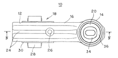
トルクロッド10は、大径の第1筒状部12と小径の第2筒状部14とを長手方向Lの両端部に各別に備えたロッド本体16と、第1筒状部12内に設けられた第1防振ブッシュ18と、第2筒状部14内に設けられた第2防振ブッシュ20とからなる。
The
ロッド本体16は、上記第1筒状部12と、第2筒状部14と、両筒状部12,14を連結する長手方向Lに延びる本体連結部22とからなり、これらがポリアミドなどの熱可塑性樹脂材料により一体に成形されている。第1筒状部12と第2筒状部14は、両者の軸O1(図5参照)及びO2(図4参照)がロッド本体16の長手方向Lに垂直に設けられるとともに、第1筒状部12の軸O1と第2筒状部14の軸O2同士も垂直に設けられている。
The rod
本体連結部22には、長手方向Lに延びる複数(ここでは3本)の補強リブ24が設けられている。これら補強リブ24は、本体連結部22から第1筒状部12に向かって延び、第1筒状部12の外周面において全周にわたって設けられている。なお、符号26は、ロッド本体16を射出成形する際の溶融樹脂の注入口となるインジェクションゲートである。
The main
第1筒状部12に設けられた第1防振ブッシュ18は、第1筒状部12内に軸平行に配された第1内筒金具28と、該第1内筒金具28を軸平行に取り囲む外筒金具30と、これら第1内筒金具28と外筒金具30の間に介設されて両者を連結するゴム弾性体からなる第1防振基体32とからなる。
The first
また、第1筒状部12よりも小径の第2筒状部14に設けられた第2防振ブッシュ20は、第2筒状部14内に軸平行に配された第2内筒金具34と、該第2内筒金具34と第2筒状部14の間に介設されたゴム弾性体からなる第2防振基体36とよりなる。
Further, the second
第2筒状部14は断面円形状をなしており、その軸O2上に第2内筒金具34が設けられている。第2防振基体36は、第2内筒金具34と第2筒状部14の間に全周にわたって設けられた筒状ゴム部材であり、第2内筒金具34の外周面に加硫接着されている。そして、第2内筒金具34の外周に加硫成形された第2防振基体36を持つ第2防振ブッシュ20は、ロッド本体16の第2筒状部14に対して軸方向に圧入することにより装着されている。
The second
これに対し、第1防振ブッシュ18は、ロッド本体16の射出成形により第1筒状部12内に結合保持されている。すなわち、第1内筒金具28と外筒金具30との間に第1防振基体32を加硫成形した後、該加硫成形体を射出成形型にセットし、インジェクションゲート26から樹脂材料を射出成形することで、第1防振ブッシュ18と一体にロッド本体16を成形し、これにより、第1筒状部12内に外筒金具30が結合保持されるように構成されている。
On the other hand, the first
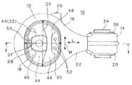
第1防振ブッシュ18の外筒金具30は、図2に示すように、第1筒状部12と第2筒状部14の対向方向(即ち、本体連結部22の長手方向L)における差渡しD1よりも、該長手方向Lに垂直な方向Mにおける差渡しD2の方が大きい断面非円形の筒状をなしている。この例では、上記長手方向Lにおける差渡し(即ち、径)D1が、長手方向に垂直な方向Mにおける差渡し(即ち、径)D2よりも小さい、断面長円形の筒状をなしている。長円形としては、図6に示す本実施形態のように、相対する2つの半円形部と、その間を連結する一対の直線部とからなるトラック形状でもよく、あるいはまた、楕円形状でもよい。
As shown in FIG. 2, the outer
また、図7,8に示されるように、外筒金具30は、軸方向両端部30A,30Aが段差部30B,30Bを介して軸方向中央部30Cよりも拡径された拡径筒部38,38に屈曲形成されている。拡径筒部38は、外筒金具30の軸方向両端部30A,30Aにおいて、全周にわたって形成されている。これにより、外筒金具30は、軸方向Xに沿った断面形状において、軸方向中央部30Cが軸直角方向内向きに陥没した凹状に形成されている。
Further, as shown in FIGS. 7 and 8, the
外筒金具30の軸方向中央部30Cには、本体連結部22側の側壁において、内外を貫通させる矩形の開口窓40が設けられている(図5,7,8参照)。これにより、外筒金具30の外周面30Dには、第1防振基体32から連なるゴム弾性体よりなる弾性膜42が被覆形成されている。弾性膜42は、図4,7に示すように、外筒金具30の外周面30Dにおいて、軸方向中央部30Cとその両側の段差部30B,30Bと更にその外側の拡径筒部38,38の一部を含む軸方向Xの略全体にわたり、かつ周方向ではその全周にわたって形成されている。但し、軸方向両端部30A,30Aともに、その先端は弾性膜42に被覆されることなく露出している。このように弾性膜42を設けたことで、図4,5に示すように、外筒金具30は、その外周面30Dが弾性膜42を介して第1筒状部12の内周面に接合されている。
A
第1防振ブッシュ18の第1防振基体32は、図2に示すように、上記長手方向Lに垂直な方向Mにおいて、第1内筒金具28を挟んだ両側で第1内筒金具28と外筒金具30の間を連結支持する上下一対の弾性連結部44,44により形成されている。詳細には、第1防振基体32には、図6,7に示すように、長手方向Lにおける第1内筒金具28を挟んだ両側に、軸方向Xに貫通する一対の空洞部46,46が設けられ、これにより、第1内筒金具28の上下一対の側面と、これに対向する外筒金具30の上下の内周面との間をつなぐ上下一対の弾性連結部44,44が設けられている。すなわち、弾性連結部44は、外筒金具30のより大きな差渡しD2側において、第1内筒金具28と外筒金具30との間を連結している。
As shown in FIG. 2, the
上記一対の空洞部46,46にはそれぞれストッパゴム部48,50が設けられており、本体連結部22側のストッパゴム部48には、断面円形状をなす軸方向Xのすぐり部52が2つ設けられている。
The pair of
以上よりなるトルクロッド10は、第1内筒金具28が車体とエンジンのいずれか一方に、第2内筒金具34が車体とエンジンのいずれか他方に連結される。詳細には、この例では、上記長手方向Lを前後方向とし、これに垂直な上記方向Mを上下方向として、第1内筒金具28がエンジン側に、第2内筒金具34が車体側に結合される。
In the
本実施形態のトルクロッド10であると、大径側の第1防振ブッシュ18の外筒金具30が断面長円形の筒状をなしているため、第1筒状部12内に結合保持された外筒金具30の周方向における回転を防止することができる。そのため、外筒金具30と第1筒状部12との接着破壊を防止して耐久性を向上することができる。
In the
しかも、外筒金具30は、第1防振基体32の弾性連結部44が設けられた上記長手方向Lに垂直な方向Mにおいて差渡しが大きく設定されているので(D2>D1)、弾性連結部44の長さを大きくして第1防振基体32の耐久性も向上することができる。
In addition, since the outer cylinder fitting 30 has a large difference in the direction M perpendicular to the longitudinal direction L in which the
よって、外筒金具30の形状により回転防止機能を持たせつつ、第1防振基体32の耐久性も向上することができる。また、断面長円形の筒体という比較的簡単な形状で回転防止機能を持たせることができるので、コストを抑えることができる。
Therefore, the durability of the
なお、外筒金具30の断面形状は、このような長円形(トラック形、楕円形)に限定されるものではなく、例えば、角部を丸めた矩形状など、種々の非円形状を適用することができる。 The cross-sectional shape of the outer cylinder fitting 30 is not limited to such an oval shape (track shape, oval shape), and various noncircular shapes such as a rectangular shape with rounded corners are applied. be able to.
本実施形態のトルクロッド10であると、また、外筒金具30の軸方向両端部30A,30Aに段差部30B,30Bを介して拡径筒部38,38を設けたので、軸方向Xにおける第1筒状部12からの外筒金具30の抜けを防止することができる。また、かかる屈曲形状とすることで、外筒金具30の強度アップを図ることができ、この点からも耐久性を向上することができる。
In the
なお、かかる拡径筒部38を設ける代わりに、外筒金具の軸方向両端部に、段差部を介して軸方向中央部よりも縮径された縮径筒部を屈曲形成してもよい。これにより、外筒金具は、軸方向に沿った断面形状において、軸方向中央部が軸直角方向外向きに膨らんだ凸状に形成される。このような縮径筒部を設けた場合にも、拡径筒部38を設けた場合と同様、外筒金具の抜け止めと強度アップを図ることができる。
Instead of providing the diameter-expanded
本実施形態のトルクロッド10であると、また、外筒金具30と樹脂製の第1筒状部12との間に弾性膜42を介在させたことにより、樹脂と金属の膨張率の差を弾性膜42により吸収して、外筒金具30と第1筒状部12との間での接合強度を高めることができ、この点からも耐久性を向上することができる。
In the
なお、上記の実施形態では、第1筒状部12に設けられる第1防振ブッシュ18のみに外筒金具30を設けた構成を採用したが、小径側の第2筒状部14に設けられる第2防振ブッシュにおいて同様の構成を採用してもよい。また、トルクロッド以外にも、スタビリンクロッド、サスペンションロッドなど、種々の防振連結ロッドとして適用可能である。その他、一々列挙しないが、本発明の趣旨を逸脱しない限り、種々の変更が可能である。
In the above-described embodiment, the configuration in which the outer cylindrical metal fitting 30 is provided only in the first
10…トルクロッド(防振連結ロッド)
12…第1筒状部
14…第2筒状部
16…ロッド本体
18…第1防振ブッシュ
20…第2防振ブッシュ
28…第1内筒金具(内筒金具)
30…外筒金具、30A…軸方向端部、30B…段差部、30C…軸方向中央部、30D…外周面
32…第1防振基体(防振基体)
38…拡径筒部
42…弾性膜
L…長手方向(第1筒状部と第2筒状部の対向方向)
M…長手方向(対向方向)に垂直な方向
D1…外筒金具の長手方向における差渡し
D2…外筒金具の長手方向に垂直な方向における差渡し
10 ... Torque rod (anti-vibration connecting rod)
DESCRIPTION OF
DESCRIPTION OF
38 ... Diameter-expanded
M: direction perpendicular to the longitudinal direction (opposite direction) D1: difference in the longitudinal direction of the outer cylinder fitting D2: difference in the direction perpendicular to the longitudinal direction of the outer cylinder fitting
Claims (3)
前記第1筒状部内に設けられた第1防振ブッシュと、
前記第2筒状部内に設けられた第2防振ブッシュと、
を備えてなり、
前記第1防振ブッシュは、前記第1筒状部内に軸平行に配された内筒金具と、前記内筒金具を軸平行に取り囲む外筒金具と、前記内筒金具と外筒金具の間に介設されて両者を連結するゴム状弾性体からなる防振基体とを備えてなり、
前記防振基体は、前記第1筒状部と第2筒状部の対向方向に垂直な方向において前記内筒金具を挟んだ両側で前記内筒金具と前記外筒金具の間を連結支持する一対の弾性連結部を有してなり、
前記外筒金具は、前記対向方向における差渡しよりも該対向方向に垂直な方向における差渡しの方が大きい断面非円形の筒状をなして、前記ロッド本体の射出成形により前記第1筒状部内に結合保持され、
前記外筒金具は、軸方向両端部が段差部を介して軸方向中央部よりも拡径又は縮径された拡径筒部又は縮径筒部に屈曲形成されてなる
ことを特徴とする防振連結ロッド。 A rod body made of a resin material having a first cylindrical part at one end and a second cylindrical part at the other end;
A first vibration isolating bush provided in the first tubular portion;
A second anti-vibration bush provided in the second tubular portion;
With
The first anti-vibration bush includes an inner cylinder fitting arranged in an axial parallel in the first cylindrical portion, an outer cylinder fitting surrounding the inner cylinder fitting in an axis parallel, and between the inner cylinder fitting and the outer cylinder fitting. An anti-vibration base made of a rubber-like elastic body interposed between the two and connecting the two,
The anti-vibration base is connected and supported between the inner tube fitting and the outer tube fitting on both sides of the inner tube fitting in a direction perpendicular to the opposing direction of the first tubular portion and the second tubular portion. Having a pair of elastic coupling parts,
The outer cylinder fitting has a cylindrical shape with a non-circular cross section in which the difference in the direction perpendicular to the facing direction is larger than the difference in the facing direction, and the first tubular shape is formed by injection molding of the rod body. Is held in the joint ,
The outer cylinder fitting is formed by bending both ends in the axial direction into a diameter-enlarged cylinder part or a diameter-reduced cylinder part whose diameter is larger or smaller than the center part in the axial direction through a step part. Vibration connecting rod.
Priority Applications (1)
| Application Number | Priority Date | Filing Date | Title |
|---|---|---|---|
| JP2008267727A JP5095577B2 (en) | 2008-10-16 | 2008-10-16 | Anti-vibration connecting rod |
Applications Claiming Priority (1)
| Application Number | Priority Date | Filing Date | Title |
|---|---|---|---|
| JP2008267727A JP5095577B2 (en) | 2008-10-16 | 2008-10-16 | Anti-vibration connecting rod |
Publications (2)
| Publication Number | Publication Date |
|---|---|
| JP2010096277A JP2010096277A (en) | 2010-04-30 |
| JP5095577B2 true JP5095577B2 (en) | 2012-12-12 |
Family
ID=42258104
Family Applications (1)
| Application Number | Title | Priority Date | Filing Date |
|---|---|---|---|
| JP2008267727A Expired - Fee Related JP5095577B2 (en) | 2008-10-16 | 2008-10-16 | Anti-vibration connecting rod |
Country Status (1)
| Country | Link |
|---|---|
| JP (1) | JP5095577B2 (en) |
Cited By (1)
| Publication number | Priority date | Publication date | Assignee | Title |
|---|---|---|---|---|
| CN105378331A (en) * | 2013-08-14 | 2016-03-02 | 山下橡胶株式会社 | Resin torque rod |
Families Citing this family (7)
| Publication number | Priority date | Publication date | Assignee | Title |
|---|---|---|---|---|
| JP5595663B2 (en) * | 2009-01-09 | 2014-09-24 | 山下ゴム株式会社 | Mount structure |
| JP2012097878A (en) * | 2010-11-05 | 2012-05-24 | Kurashiki Kako Co Ltd | Vibration control connecting rod |
| JP5913848B2 (en) * | 2011-07-13 | 2016-04-27 | 日産自動車株式会社 | Torque rod |
| JP6266955B2 (en) * | 2013-11-20 | 2018-01-24 | 住友理工株式会社 | Torque rod |
| JP5712312B2 (en) * | 2014-04-14 | 2015-05-07 | 山下ゴム株式会社 | Mount structure |
| JP6482159B2 (en) * | 2015-02-24 | 2019-03-13 | Toyo Tire株式会社 | Connecting member |
| FR3062438B1 (en) * | 2017-02-02 | 2019-03-22 | Safran Transmission Systems | TURBOMACHINE ROD WITH INTEGRATED FILTER AND METHOD FOR PRODUCING THE SAME |
Family Cites Families (7)
| Publication number | Priority date | Publication date | Assignee | Title |
|---|---|---|---|---|
| JPS596444A (en) * | 1982-07-03 | 1984-01-13 | Nissan Motor Co Ltd | Vibroisolating rubber |
| JPH08233030A (en) * | 1994-12-28 | 1996-09-10 | Bridgestone Corp | Coupling rod |
| JPH10205561A (en) * | 1997-01-20 | 1998-08-04 | Toyoda Gosei Co Ltd | Vibration proofing device |
| JPH11351330A (en) * | 1998-06-10 | 1999-12-24 | Fuji Heavy Ind Ltd | Structure of connecting member such as pitching stopper |
| JP2000266122A (en) * | 1999-03-15 | 2000-09-26 | Toyoda Gosei Co Ltd | Vibration control mount |
| JP3661060B2 (en) * | 2000-09-20 | 2005-06-15 | 東洋ゴム工業株式会社 | Vibration isolator |
| JP4658665B2 (en) * | 2005-04-11 | 2011-03-23 | 株式会社ブリヂストン | Vibration isolator |
-
2008
- 2008-10-16 JP JP2008267727A patent/JP5095577B2/en not_active Expired - Fee Related
Cited By (1)
| Publication number | Priority date | Publication date | Assignee | Title |
|---|---|---|---|---|
| CN105378331A (en) * | 2013-08-14 | 2016-03-02 | 山下橡胶株式会社 | Resin torque rod |
Also Published As
| Publication number | Publication date |
|---|---|
| JP2010096277A (en) | 2010-04-30 |
Similar Documents
| Publication | Publication Date | Title |
|---|---|---|
| JP5095577B2 (en) | Anti-vibration connecting rod | |
| JP5230390B2 (en) | Anti-vibration connecting rod | |
| JP4740818B2 (en) | Link member with anti-vibration bush | |
| JP2008223920A (en) | Vibration control bush and vibration control bush assembly | |
| JP6343535B2 (en) | Cylindrical vibration isolator | |
| JP2012097878A (en) | Vibration control connecting rod | |
| JP2017067157A (en) | Cylindrical vibration-proof device with bracket | |
| JP2009115109A (en) | Vibration isolating connecting rod | |
| JP5615677B2 (en) | Anti-vibration connecting rod | |
| JP2007333029A (en) | Torque rod | |
| JP4694815B2 (en) | Torque rod and manufacturing method thereof | |
| JP2000161434A (en) | Vibration proof bush | |
| JPH1128920A (en) | Suspension arm | |
| JP4607938B2 (en) | Anti-vibration connecting rod | |
| JP2006189096A (en) | Torque rod | |
| JP4442371B2 (en) | Torque rod | |
| WO2020129514A1 (en) | Bracket | |
| JPS63270913A (en) | Connecting rod with rubber bush | |
| JPH1182625A (en) | Stabilizer bush | |
| JP4218358B2 (en) | Cylindrical vibration isolator | |
| JP5318731B2 (en) | Vibration isolator | |
| JP4664172B2 (en) | bush | |
| JP3456286B2 (en) | Cylindrical anti-vibration mount | |
| JP2005212779A (en) | Stabilizer bush | |
| JP7291564B2 (en) | Synthetic resin strength member for vehicle |
Legal Events
| Date | Code | Title | Description |
|---|---|---|---|
| A621 | Written request for application examination |
Free format text: JAPANESE INTERMEDIATE CODE: A621 Effective date: 20110630 |
|
| A977 | Report on retrieval |
Free format text: JAPANESE INTERMEDIATE CODE: A971007 Effective date: 20120523 |
|
| A131 | Notification of reasons for refusal |
Free format text: JAPANESE INTERMEDIATE CODE: A131 Effective date: 20120529 |
|
| A521 | Request for written amendment filed |
Free format text: JAPANESE INTERMEDIATE CODE: A523 Effective date: 20120711 |
|
| TRDD | Decision of grant or rejection written | ||
| A01 | Written decision to grant a patent or to grant a registration (utility model) |
Free format text: JAPANESE INTERMEDIATE CODE: A01 Effective date: 20120911 |
|
| A01 | Written decision to grant a patent or to grant a registration (utility model) |
Free format text: JAPANESE INTERMEDIATE CODE: A01 |
|
| A61 | First payment of annual fees (during grant procedure) |
Free format text: JAPANESE INTERMEDIATE CODE: A61 Effective date: 20120919 |
|
| R150 | Certificate of patent or registration of utility model |
Ref document number: 5095577 Country of ref document: JP Free format text: JAPANESE INTERMEDIATE CODE: R150 Free format text: JAPANESE INTERMEDIATE CODE: R150 |
|
| FPAY | Renewal fee payment (event date is renewal date of database) |
Free format text: PAYMENT UNTIL: 20150928 Year of fee payment: 3 |
|
| R250 | Receipt of annual fees |
Free format text: JAPANESE INTERMEDIATE CODE: R250 |
|
| S531 | Written request for registration of change of domicile |
Free format text: JAPANESE INTERMEDIATE CODE: R313531 |
|
| R350 | Written notification of registration of transfer |
Free format text: JAPANESE INTERMEDIATE CODE: R350 |
|
| R250 | Receipt of annual fees |
Free format text: JAPANESE INTERMEDIATE CODE: R250 |
|
| S533 | Written request for registration of change of name |
Free format text: JAPANESE INTERMEDIATE CODE: R313533 |
|
| R350 | Written notification of registration of transfer |
Free format text: JAPANESE INTERMEDIATE CODE: R350 |
|
| LAPS | Cancellation because of no payment of annual fees |