JP3661060B2 - Vibration isolator - Google Patents
Vibration isolator Download PDFInfo
- Publication number
- JP3661060B2 JP3661060B2 JP2002528706A JP2002528706A JP3661060B2 JP 3661060 B2 JP3661060 B2 JP 3661060B2 JP 2002528706 A JP2002528706 A JP 2002528706A JP 2002528706 A JP2002528706 A JP 2002528706A JP 3661060 B2 JP3661060 B2 JP 3661060B2
- Authority
- JP
- Japan
- Prior art keywords
- cylinder fitting
- vibration
- convex portion
- inner cylinder
- fitting
- Prior art date
- Legal status (The legal status is an assumption and is not a legal conclusion. Google has not performed a legal analysis and makes no representation as to the accuracy of the status listed.)
- Expired - Lifetime
Links
Images


Classifications
-
- F—MECHANICAL ENGINEERING; LIGHTING; HEATING; WEAPONS; BLASTING
- F16—ENGINEERING ELEMENTS AND UNITS; GENERAL MEASURES FOR PRODUCING AND MAINTAINING EFFECTIVE FUNCTIONING OF MACHINES OR INSTALLATIONS; THERMAL INSULATION IN GENERAL
- F16F—SPRINGS; SHOCK-ABSORBERS; MEANS FOR DAMPING VIBRATION
- F16F1/00—Springs
- F16F1/36—Springs made of rubber or other material having high internal friction, e.g. thermoplastic elastomers
- F16F1/38—Springs made of rubber or other material having high internal friction, e.g. thermoplastic elastomers with a sleeve of elastic material between a rigid outer sleeve and a rigid inner sleeve or pin, i.e. bushing-type
- F16F1/387—Springs made of rubber or other material having high internal friction, e.g. thermoplastic elastomers with a sleeve of elastic material between a rigid outer sleeve and a rigid inner sleeve or pin, i.e. bushing-type comprising means for modifying the rigidity in particular directions
- F16F1/3873—Springs made of rubber or other material having high internal friction, e.g. thermoplastic elastomers with a sleeve of elastic material between a rigid outer sleeve and a rigid inner sleeve or pin, i.e. bushing-type comprising means for modifying the rigidity in particular directions having holes or openings
Description
【0001】
【技術分野】
本発明は、主として自動車のエンジンマウントやサスペンションブッシュ等として使用される防振装置に関する。
【0002】
【背景技術】
従前より、自動車のエンジンマウントやサスペンションブッシュ等に用いられる防振装置として、内筒金具と外筒金具とを両金具間に介設したゴム弾性体により結合したものが知られている。通常、内筒金具がこれに挿嵌される軸部材を介して略コの字状をなす、一方の支持部材に取り付けられ、外筒金具が、ブラケット等の他方の支持部材に圧入されて固定される。これら支持部材は、エンジン等の振動源と、車体等の支持側とにそれぞれ設けられる。
【0003】
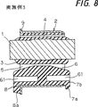
図13に、このような防振装置の一従来例を示す。
【0004】
図に示すように、内筒金具101と外筒金具102との間に介設されるゴム弾性体103は、内筒金具101の上下にそれぞれ空洞部104,105を有し、下側の空洞部105に、上方へと突出する凸部106を有する。該凸部106は、エンジン等を支持し荷重を受けた状態で、該下側空洞部105の天井面151に突き当てられる。したがって、ゴム弾性体103は、軸方向を前後方向とした場合において左右両側から内筒金具101を支持するとともに、荷重を受けた状態では凸部106によっても内筒金具101の個所を支持する。すなわち、凸部106がある程度の荷重を分担するのである。そして、好適な使用状態においては、荷重下において内筒金具101が、外筒金具102のなす断面形状の略中心に配置される。
【0005】
また、図に示すように、外筒金具102は、主として略楕円形ないしは小判形の断面を有し、その長軸が横方向(Y方向)に向けられている。すなわち、外筒金具102は、筒型の防振装置の軸方向を車両に対し前後方向(X方向)にして使用する場合において、左右方向(Y方向)に長い略楕円形の断面を有する。これは、内筒金具101が左右から充分な量のゴム弾性体により支持される必要や防振特性の安定性等のためである。
【0006】
上記の防振装置は、通常、自動車の車体からエンジンを支持して静置するような基本負荷時において、凸部が下側空洞部の天井面に当接するように設計される。
【0007】
そのため、上下方向(Z方向)の動バネ定数が高くなりがちである。動バネ定数が高くなりすぎた場合、比較的振幅の小さい振動に対する防振特性が不充分になる等の問題が生じる。
【0008】
動バネ定数を適宜に小さくしようとして、凸部106の幅寸法(図13におけるY方向寸法)を全体に削った場合には、防振装置全体の上下方向(Z方向)の動バネ定数における凸部106の寄与比率(分担割合)が変化してしまう。そして、基本荷重時における内筒金具101の位置、すなわちエンジンを支持する位置が変化してしまう。また、凸部106が大変形を規制するストッパーバネとして作用する際のバネ力が低下することにより、振動を受けた際のストロークが過大なものになってしまう。バネ力が低下すると、荷重―たわみ曲線で見た場合に、所定の振動ピークでの荷重に対応するたわみの値は、大変形の側へとシフトするのである。したがって、防振装置の耐久性が低下してしまうこととなる。
【0009】
本発明は、上記問題点に鑑みなされたものであり、内筒金具と外筒金具がゴム弾性体により結合されてなり、ゴム弾性体が内筒金具の上下に空洞部を有する防振マウントであって、下側の空洞部には上方へと突き出して荷重下において該空洞部の天井面が当接する凸部が備えられるものにおいて、耐久性を損なうことなく、上下方向の動バネ定数を適宜低下させることができるものを提供する。
【0010】
【発明の開示】
本発明の防振装置は、内筒金具と、この外方を囲むように配された外筒金具とが、これら内外の金具間に介設されたゴム弾性体により結合されてなり、前記ゴム弾性体は、前記内筒金具の上下にそれぞれ上側空洞部及び下側空洞部を有し、前記下側空洞部には、外筒金具の側から上方の内筒金具に向かって突出する凸部が設けられ、標準荷重下において前記下側空洞部の天井面が前記凸部の先端面に当接する防振装置において、前記凸部中に軸方向の小空洞が設けられており、該小空洞が上下方向における所定以上の振幅の振動時に潰れて壁面が密着することで前記凸部が前記内筒金具の下方への変位を規制するストッパ作用を果たすように設けられたことを特徴とする。そして、第1の発明では更に、前記小空洞は、軸方向の貫通孔からなり、該貫通孔の両端開口から軸方向中央部まで径が徐々に小さくなっていることを特徴とする。また、第2の発明では、前記凸部の外面に軸方向に延びる複数の溝が設けられたことを特徴とする。
【0011】
上記構成により、前記凸部は前記小空洞の存在のために、ある振幅範囲までは小空洞を有さない凸部に比して弾性変形し易くて、上下方向の動バネ定数を低下させることができる。しかも、振幅の大きい振動時には、前記小空洞が潰れて壁面が密着することで、大変形を規制するストッパーバネとしてのバネ力が大きくなり、良好なストッパ作用を果たす。したがって、耐久性を低下させることなく、上下方向の動バネ定数を下げることができ、小振幅の振動時においても良好かつ充分な防振特性を保持できる。
【0012】
前記の防振装置において、前記外筒金具が横に長い略楕円形の断面を有し、前記内筒金具が無荷重状態において前記外筒金具に対して上方に偏心して配置され、前記ゴム弾性体が前記外筒金具の断面における左右両側から前記内筒金具を支持しているものが好ましい。
【0013】
これにより、前記防振装置の軸方向を前後方向とした場合、左右方向に長い略楕円形の断面を有することで、内筒金具が左右から充分な量のゴム弾性体により支持され、防振特性が安定する。
【0014】
前記凸部中の小空洞として、上記第2の発明では軸方向の貫通孔である場合、軸方向の非貫通孔である場合のいずれでもよい。また前記凸部中に、複数の小空洞を設けることもできる。これらの孔の径、形状、数等により、凸部の剛性を適宜設定できる。
【0015】
【発明を実施するための最良の形態】
本発明の実施例1について、図1〜5を用いて説明する。
【0016】
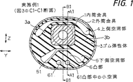
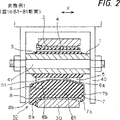
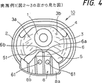
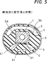
実施例の防振装置は、エンジンを自動車の車体側の支持部材から吊り下げて支持する、エンジン用の防振マウントである。図1は、筒状の防振マウント10を軸方向中央部にて切断した断面図(図3のC1−C1線の断面図)である。図2は、防振マウント10を軸方向から見て左右に等分するように切断した断面図(図1のB1−B1線の断面図)、すなわち左右の対称線に沿って切断した断面図である。図2では、特に、上下からの支持部材30,40に取り付けられた状態での防振マウント10を示している。一方、図3は、左右の対称線から少しずらして切断した場合の図2と同様の断面図(図1のA1−A1線の断面図)であり、図4は、図2〜3の左側から見た防振マウント10の正面図である。また、図5は、標準荷重を受けて変形した状態を示す図1と同様の断面図である。
【0017】
この防振マウント10は、比較的厚肉の筒状をなす内筒金具1と、その外方を囲むように配された外筒金具2とが、これら金具1,2間に介設されてゴム弾性体3により結合されてなる。このゴム弾性体3は、ゴム加硫成形により、一体に成形されるとともに、内筒金具1及び外筒金具2に接着される。
【0018】
内筒金具1の外面は、軸方向に垂直な断面において、防振マウント10の軸方向中央部付近では若干横方向に長い矩形状をなすが、その他の個所では円形をなす。すなわち、内筒金具1は、軸方向中央部近傍において、角状に外側へ突き出す「バルジ」を備えている。一方、内筒金具1の内面は、円柱状の軸部材41を受け入れるように、全体が径の均一な円筒をなしている。円柱状の軸部材41は、図2に示すように、断面が横に倒れたコの字状をなす支持部材40により、上方の車体側から支持される。
【0019】
外筒金具2は、図2〜3に示すように内筒金具1よりも軸方向(X方向)寸法がやや小さく、図1に示すように、軸方向に垂直な断面において、左右方向(Y方向)を長軸とする略楕円状ないし小判状の形状をなしている。外筒金具2は、図2に示すように、下側の支持部材30に設けられた水平の取り付け孔に圧入されている。下側の支持部材30は、防振マウント10の使用状態において、エンジンを吊り下げるものである。
【0020】
防振マウント10の非荷重時、すなわち、内筒金具1と外筒金具2との間に荷重がかかっていない状態では、図1等に示すように、内筒金具1が外筒金具2に対して上方に偏心して配置される。
【0021】
内筒金具1と外筒金具2との間を埋めるゴム弾性体3は、内筒金具1の上下に、軸方向の貫通孔よりなる空洞部4,5を有している。これにより、前記ゴム弾性体3の支持腕としての両側部分3a,3bが前記外筒金具2の断面における左右両側から前記内筒金具1を支持した状態になっている。これら空洞部4,5は、軸方向に対して垂直な断面(図1の左右方向断面)において、上方に向かって膨出する弓状をなし、両端部で幅広となっている。図1に示すように、上側空洞部4は、外筒金具2の内面からわずかな間隔を保持するように延びており、下側空洞部5は、上端部が内筒金具1の下面から少し離されて配置される。
【0022】
下側空洞部5の下面は、外筒金具2の側から上方の内筒金具1へと向かって突き出しており、これにより、下方への変位を規制するストッパーとしての凸部6がゴム弾性体3と一体に形成されている。凸部6は、図1〜2に示すように、左右方向(Y方向)断面及び軸方向(X方向、前後方向)断面のいずれにおいても、略台形状をなしている。したがって、凸部6の上端面6aは、軸方向中央部において水平な平坦面をなす。この凸部上端面6aは、非荷重時に、全体が平坦で水平な、下側空洞部5の天井面51からわずかな間隔を置いて離間されている。荷重時においては、図5に示すように、凸部6の先端面つまり上端面6aが、下側空洞部5の天井面51に当接される。
【0023】
なお、詳細には、図4に示すように、凸部6の外面に、軸方向に延びる溝6bが複数設けられており、凸部6の対称線に沿って設けられているので、凸部上端面6aは、完全な平坦面ではなくある程度の凹凸がある。凸部上端面6aが、他の凹凸形状、例えば、全体に波状の形状を有する場合や、溝6bの幅及び深さ寸法が、より大きい場合であっても、後述するような得られる効果において、ほぼ同様である。
【0024】
一方、凸部6の根元付近には、左右対称に、軸方向の貫通孔からなる2つの小空洞61が設けられる。小空洞61は、図1、及び図3の断面図(図1のA1−A1線の断面)から知られるように、軸方向に径が均一な円筒形の貫通孔である。
【0025】
小空洞61を設けるためには、例えば、ゴム弾性体3を内筒金具1と外筒金具2に介挿された状態で加硫する加硫成形時に、上側及び下側空洞部4,5と同様に、中子により作製することができる。または、加硫成形の後にくり抜くことも可能である。いずれにしても簡単な操作により設けることができる。
【0026】
このように、凸部6中に小空洞61が設けられることにより、防振マウント10における上下方向(Z方向)の動バネ定数を容易に低減することができた。
【0027】
すなわち、エンジン等を支持した荷重状態下で、前記凸部6が前記下側空洞部5の天井面51に当接して内筒金具1を支持した状態において、前記凸部6は、前記小空洞61の存在のために、ある変形範囲までは小空洞を有さない凸部6に比して弾性変形し易くなっており、それだけ上下方向の動バネ定数を低下させることができる。しかも、振幅の大きい振動時には、前記小空洞61が潰れてその壁面が密着することで、大変形を規制するストッパーバネとしてのバネ力が大きくなり、良好なストッパ作用を果たす。それゆえ、耐久性を低下させることなく、上下方向の動バネ定数を下げることができる。
【0028】
具体的な試験例について述べるならば、図13の従来例を基準とした場合、15Hzにおける上下方向(Z方向)の動バネ定数(Kd15)を500N/mmから410N/mmへと18%低減し、100Hzにおける上下方向の動バネ定数(Kd100)を560N/mmから470N/mmへと16%低減することができた。
【0029】
このとき、凸部6による分担荷重は、凸部6の幅(左右方向寸法)をわずかに増加させることにより、従来例と同じ1570Nに維持されている。このように、凸部6の分担荷重を維持できるため、動バネ定数を低減させても、荷重時における内筒金具1と外筒金具2との相対位置を変化させたり、振動によるストロークを増大させることがない。したがって、動バネ定数を低減させても、防振マウント10の耐久性を損なうことがない。
【0030】
一方、凸部6の左右幅寸法を削って同様に試験を行った比較例においては、凸部6の分担荷重が1570Nから1250Nに低下したにも拘わらず、15Hz及び100Hzにおける上下方向の動バネ定数の低下は、それぞれ、11%及び10%にとどまった。
【0031】
なお、図2〜3及び図4に示すように、凸部6の軸方向両端には、軸方向に突出するストッパゴム部7,8が設けられている。ストッパゴム部7,8は、それぞれが、軸方向に外側に突出してから下方に延在されてなる外縁部7a,8aを備え、上方の支持部材40に対する突き当て面7b,8bを形成している。これにより、ストッパゴム部7,8は、金属同士の干渉を防止する役割を果たす。
【0032】
以上に説明したように、本実施例によると、凸部6中に小空洞61を設けるだけで、凸部6の分担荷重を変化させることなく、防振マウントの上下方向における動バネ定数を大幅に低減することができる。
【0033】
なお、前記凸部6に設ける小空洞61の形状、大きさ、数、配置等は、求める動バネ定数や防振特性等に応じて種々の変更が可能である。
【0034】
以下、図6〜11を用いて実施例2〜6について説明する。
【0035】
図6〜7に示す実施例2では、実施例1と同様の構成において、凸部6中の小空洞61として、一つの貫通孔のみが設けられている。この変形例における小空洞61は、左右方向に対する対称線(図6のD−D線)上に中心が位置する円形の断面形状を有し、貫通孔の両端開口から軸方向中央部に向かって径が徐々に小さくなっている。
【0036】
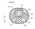
図8に示す実施例3では、実施例と同様の構成において、凸部6中の小空洞61が非貫通孔により形成されている。すなわち、実施例における2つの貫通孔が軸方向中央部において塞がれたような構造となっている。
【0037】
これら実施例2〜3の構成によっても、実施例と同様の効果を得ることができる。
【0038】
図9に示す実施例4においては、実施例1と同様の構成において、貫通孔である2つの小空洞61の断面が、角のとれた三角形の形状を有する。また、図10に示す実施例5においては、貫通孔として設けられる小空洞61が、一つの、左右に長い、扁平な楕円状の断面を有する。一方、図11においては、小空洞61として、左右対称線上に位置し上下方向に長い略楕円状の断面を有する一つの貫通孔61aと、これより下方に左右対称に設けられる断面円形の2つの貫通孔61bとが設けられている。
【0039】
これら実施例4〜6の構成によっても、実施例1とほぼ同様の効果を得ることができる。
【0040】
上記のいずれの実施例においても、外筒金具2については、断面が横長の略楕円状ないし小判状をなす場合を示したが、本発明は、図12に示す実施例7のように、外筒金具2の断面が円形をなすものにおいても同様に実施できる。
【0041】
すなわち、この実施例7の場合、外筒金具2と内筒金具1との間に介設したゴム弾性体3に、上側空洞部4と下側空洞部5とを設け、下側空洞部5に外側金具2の側から上方に突出しかつ一定の荷重下で下側空洞部5の天井面51が当接する凸部6を設けている。そして、前記凸部6に上記した実施例と同様の小空洞61を設ける。この小空洞61の形状、大きさ、数、配置等については、種々の変更が可能である。この場合も、上記と同様の効果を発揮できる。
【0062】
【産業上の利用可能性】
上記のように本発明の防振装置は、耐久性を損なうことなく、上下方向の動バネ定数を適宜低下させることができるので、主に自動車のエンジンマウントやサスペンションブッシュ等として好適に使用できる。
【図面の簡単な説明】
【図1】実施例1の筒状の防振マウント10を軸方向中央部にて切断した無荷重状態での断面図(図3のC1−C1線の断面図)である。
【図2】実施例1の防振マウント10を軸方向から見て左右に等分するように切断した断面図(図1のB1−B1線の断面図)である。特には、上下からの支持部材に取り付けられた状態を示す。
【図3】実施例1の防振マウント10について、凸部6中の小空洞61を左右に等分するように切断した断面図(図1のA1−A1線の断面図)である。
【図4】実施例1の防振マウント10について、支持部材30へ圧入する際の後方から見た(図2〜3の左側から見た)正面図である。
【図5】実施例1の防振マウント10について、標準荷重下での状態を示す図1に対応する断面図である。
【図6】実施例2の防振マウントについての図1に対応する断面図である。
【図7】実施例2の防振マウントについての図2に対応する断面図である。
【図8】実施例3の防振マウントについての図3に対応する断面図である。
【図9】実施例4の防振マウントについての図1に対応する断面図である。
【図10】実施例5の防振マウントについての図1に対応する断面図である。
【図11】実施例6の防振マウントについての図1に対応する断面図である。
【図12】実施例7の円形の防振マウント10を軸方向中央部にて切断した断面図である。無荷重での状態を示す。
【図13】従来例の防振マウントについての図1に対応する断面図である。 [0001]
【Technical field】
The present invention relates to a vibration isolator mainly used as an engine mount, a suspension bush or the like of an automobile.
[0002]
[Background]
2. Description of the Related Art Conventionally, as an anti-vibration device used for an engine mount, a suspension bush or the like of an automobile, an apparatus in which an inner cylinder fitting and an outer cylinder fitting are coupled by a rubber elastic body interposed between the two fittings is known. Normally, the inner cylinder fitting is attached to one support member having a substantially U-shape through a shaft member inserted into the inner cylinder fitting, and the outer cylinder fitting is press-fitted and fixed to the other support member such as a bracket. Is done. These support members are provided on a vibration source such as an engine and a support side such as a vehicle body.
[0003]
FIG. 13 shows a conventional example of such a vibration isolator.
[0004]
As shown in the figure, the rubber
[0005]
Further, as shown in the figure, the
[0006]
The above vibration isolator is usually designed so that the convex portion comes into contact with the ceiling surface of the lower cavity portion at the time of a basic load in which the engine is supported from the vehicle body of the automobile and left stationary.
[0007]
For this reason, the dynamic spring constant in the vertical direction (Z direction) tends to be high. When the dynamic spring constant becomes too high, problems such as insufficient vibration-proofing properties against vibrations having a relatively small amplitude arise.
[0008]
When the width dimension of the convex portion 106 (the Y-direction dimension in FIG. 13 ) is entirely cut in an attempt to appropriately reduce the dynamic spring constant, the convexity in the dynamic spring constant in the vertical direction (Z direction) of the entire vibration isolator is obtained. The contribution ratio (sharing ratio) of the
[0009]
The present invention has been made in view of the above problems, and is an anti-vibration mount in which an inner cylinder fitting and an outer cylinder fitting are joined by a rubber elastic body, and the rubber elastic body has hollow portions above and below the inner cylinder fitting. The lower cavity is provided with a convex portion that protrudes upward and abuts against the ceiling surface of the cavity under load, and the vertical dynamic spring constant is appropriately set without impairing durability. Provide what can be lowered.
[0010]
DISCLOSURE OF THE INVENTION
The vibration isolator according to the present invention includes an inner cylinder fitting and an outer cylinder fitting arranged so as to surround the outside by a rubber elastic body interposed between the inner and outer fittings. The elastic body has an upper cavity portion and a lower cavity portion on the upper and lower sides of the inner cylinder fitting, respectively, and the lower cavity portion has a convex portion protruding from the outer cylinder fitting side toward the upper inner cylinder fitting. In the vibration isolator in which the ceiling surface of the lower cavity portion is in contact with the tip surface of the convex portion under a standard load, a small axial cavity is provided in the convex portion, and the small cavity Is provided such that the convex portion is provided with a stopper function that restricts the downward displacement of the inner cylindrical metal fitting by being crushed during vibration of a predetermined amplitude or more in the vertical direction and closely contacting the wall surface . In the first invention, the small cavity is formed of an axial through hole, and the diameter gradually decreases from the opening at both ends of the through hole to the central portion in the axial direction. Further, the second invention is characterized in that a plurality of grooves extending in the axial direction are provided on the outer surface of the convex portion.
[0011]
With the above configuration, because of the presence of the small cavity, the convex portion is more easily elastically deformed than a convex portion having no small cavity up to a certain amplitude range, and lowers the vertical dynamic spring constant. Can do. Moreover, when the vibration has a large amplitude, the small cavity is crushed and the wall surfaces are brought into close contact with each other, so that a spring force as a stopper spring for restricting large deformation is increased, and a satisfactory stopper action is achieved. Therefore, the dynamic spring constant in the vertical direction can be lowered without lowering the durability, and good and sufficient vibration-proof characteristics can be maintained even at the time of small amplitude vibration.
[0012]
In the above vibration isolator, the outer cylinder fitting has a substantially elliptical cross section that is long horizontally, and the inner cylinder fitting is arranged eccentrically upward with respect to the outer cylinder fitting in a no-load state, and the rubber elastic It is preferable that the body supports the inner cylinder fitting from the left and right sides in the cross section of the outer cylinder fitting.
[0013]
As a result, when the axial direction of the vibration isolator is the front-rear direction, the inner cylinder fitting is supported by a sufficient amount of rubber elastic body from the left and right by having a substantially elliptical cross section that is long in the left-right direction. The characteristics are stable.
[0014]
In the second aspect , the small cavity in the convex portion may be an axial through hole or an axial non-through hole. A plurality of small cavities can also be provided in the convex portion. The rigidity of the convex portion can be set as appropriate depending on the diameter, shape, number, etc. of these holes.
[0015]
BEST MODE FOR CARRYING OUT THE INVENTION
A first embodiment of the present invention will be described with reference to FIGS.
[0016]
The vibration isolator of the embodiment is an anti-vibration mount for an engine that supports the engine by suspending it from a support member on the vehicle body side of the automobile. FIG. 1 is a cross-sectional view (cross-sectional view taken along line C1-C1 in FIG. 3) in which a cylindrical vibration-
[0017]
This
[0018]
In the cross section perpendicular to the axial direction, the outer surface of the inner
[0019]
The outer cylinder fitting 2 is slightly smaller in the axial direction (X direction) than the inner cylinder fitting 1 as shown in FIGS. 2 to 3, and as shown in FIG. It has a substantially elliptical or oval shape with the direction as the major axis. As shown in FIG. 2, the outer cylinder fitting 2 is press-fitted into a horizontal attachment hole provided in the
[0020]
When the
[0021]
A rubber
[0022]
The lower surface of the
[0023]
In detail, as shown in FIG. 4, a plurality of
[0024]
On the other hand, in the vicinity of the root of the
[0025]
In order to provide the
[0026]
Thus, by providing the
[0027]
That is, in a state in which the
[0028]
To describe a specific test example, when the conventional example of FIG. 13 is used as a reference, the dynamic spring constant (Kd15) in the vertical direction (Z direction) at 15 Hz is reduced by 18% from 500 N / mm to 410 N / mm. The dynamic spring constant (Kd100) in the vertical direction at 100 Hz could be reduced by 16% from 560 N / mm to 470 N / mm.
[0029]
At this time, the shared load by the
[0030]
On the other hand, in the comparative example in which the left and right width dimensions of the
[0031]
As shown in FIGS. 2 to 3 and FIG. 4,
[0032]
As described above, according to the present embodiment, the dynamic spring constant in the vertical direction of the anti-vibration mount can be greatly increased by merely providing the
[0033]
The shape, size, number, arrangement, etc. of the
[0034]
Hereinafter, Examples 2 to 6 will be described with reference to FIGS.
[0035]
In the second embodiment shown in FIGS. 6 to 7, in the same configuration as the first embodiment, only one through hole is provided as the
[0036]
In Example 3 shown in FIG. 8, the
[0037]
Effects similar to those of the embodiment can be obtained by the configurations of the
[0038]
In Example 4 shown in FIG. 9, the cross section of the two
[0039]
Even with the configurations of the fourth to sixth embodiments, substantially the same effects as those of the first embodiment can be obtained.
[0040]
In any of the above-described embodiments, the outer
[0041]
That is, in the case of this Example 7, the
[0062]
[Industrial applicability]
As described above, the vibration isolator of the present invention can appropriately reduce the vertical dynamic spring constant without impairing the durability, and therefore can be suitably used mainly as an engine mount, a suspension bush or the like of an automobile.
[Brief description of the drawings]
FIG. 1 is a cross-sectional view (a cross-sectional view taken along line C1-C1 in FIG. 3) in a no-load state in which a cylindrical vibration-
2 is a cross-sectional view (cross-sectional view taken along line B1-B1 in FIG. 1) in which the
3 is a cross-sectional view (a cross-sectional view taken along the line A1-A1 in FIG. 1) of the
4 is a front view of the
5 is a cross-sectional view corresponding to FIG. 1 showing a state under a standard load with respect to the
6 is a cross-sectional view corresponding to FIG. 1 of a vibration-proof mount of Example 2. FIG.
7 is a cross-sectional view corresponding to FIG. 2 of the vibration-proof mount of Example 2. FIG.
8 is a cross-sectional view corresponding to FIG. 3 of the vibration-proof mount of Example 3. FIG.
9 is a cross-sectional view corresponding to FIG. 1 of a vibration-proof mount of Example 4. FIG.
10 is a cross-sectional view corresponding to FIG. 1 of the vibration-proof mount of Example 5. FIG.
11 is a cross-sectional view corresponding to FIG. 1 of a vibration-proof mount of Example 6. FIG.
12 is a cross-sectional view of a
13 is a cross-sectional view corresponding to FIG. 1 of a conventional vibration-proof mount. FIG.
Claims (2)
前記凸部中に軸方向の小空洞が設けられており、該小空洞が上下方向における所定以上の振幅の振動時に潰れて壁面が密着することで前記凸部が前記内筒金具の下方への変位を規制するストッパ作用を果たすように設けられ、
前記小空洞は、軸方向の貫通孔からなり、該貫通孔の両端開口から軸方向中央部まで径が徐々に小さくなっていることを特徴とする防振装置。An inner cylinder fitting and an outer cylinder fitting arranged so as to surround the outside are joined by a rubber elastic body interposed between the inner and outer fittings, and the rubber elastic body is formed by the inner cylinder fitting. Each of the upper and lower cavities has an upper cavity portion and a lower cavity portion, and a convex portion projecting from the outer cylinder fitting side toward the upper inner cylinder fitting is provided on the lower cavity portion, and a standard load is provided. In the vibration isolator where the ceiling surface of the lower cavity portion is in contact with the tip surface of the convex portion,
A small cavity in the axial direction is provided in the convex part, and the small cavity is crushed at the time of vibration of a predetermined amplitude or more in the vertical direction and the wall surface is in close contact, so that the convex part is below the inner cylindrical metal fitting. Provided to serve as a stopper that regulates displacement,
The small cavity includes an axial through hole, and the diameter gradually decreases from both end openings of the through hole to the central portion in the axial direction .
前記凸部中に軸方向の小空洞が設けられており、該小空洞が上下方向における所定以上の振幅の振動時に潰れて壁面が密着することで前記凸部が前記内筒金具の下方への変位を規制するストッパ作用を果たすように設けられ、
前記凸部の外面に軸方向に延びる複数の溝が設けられたことを特徴とする防振装置。An inner cylinder fitting and an outer cylinder fitting arranged so as to surround the outside are joined by a rubber elastic body interposed between the inner and outer fittings, and the rubber elastic body is formed by the inner cylinder fitting. Each of the upper and lower cavities has an upper cavity portion and a lower cavity portion, and a convex portion projecting from the outer cylinder fitting side toward the upper inner cylinder fitting is provided on the lower cavity portion, and a standard load is provided. In the vibration isolator where the ceiling surface of the lower cavity portion is in contact with the tip surface of the convex portion,
A small cavity in the axial direction is provided in the convex part, and the small cavity is crushed at the time of vibration of a predetermined amplitude or more in the vertical direction and the wall surface is in close contact, so that the convex part is below the inner cylindrical metal fitting. Provided to serve as a stopper that regulates displacement,
A vibration isolator comprising a plurality of grooves extending in the axial direction on an outer surface of the convex portion .
Applications Claiming Priority (3)
| Application Number | Priority Date | Filing Date | Title |
|---|---|---|---|
| JP2000285580 | 2000-09-20 | ||
| JP2000285580 | 2000-09-20 | ||
| PCT/JP2001/007621 WO2002025138A1 (en) | 2000-09-20 | 2001-09-03 | Vibration isolator |
Related Child Applications (1)
| Application Number | Title | Priority Date | Filing Date |
|---|---|---|---|
| JP2005016188A Division JP2005172242A (en) | 2000-09-20 | 2005-01-24 | Vibration control device |
Publications (2)
| Publication Number | Publication Date |
|---|---|
| JPWO2002025138A1 JPWO2002025138A1 (en) | 2004-01-29 |
| JP3661060B2 true JP3661060B2 (en) | 2005-06-15 |
Family
ID=18769626
Family Applications (1)
| Application Number | Title | Priority Date | Filing Date |
|---|---|---|---|
| JP2002528706A Expired - Lifetime JP3661060B2 (en) | 2000-09-20 | 2001-09-03 | Vibration isolator |
Country Status (2)
| Country | Link |
|---|---|
| JP (1) | JP3661060B2 (en) |
| WO (1) | WO2002025138A1 (en) |
Families Citing this family (5)
| Publication number | Priority date | Publication date | Assignee | Title |
|---|---|---|---|---|
| WO2006070440A1 (en) * | 2004-12-27 | 2006-07-06 | Toyo Tire & Rubber Co., Ltd. | Link device |
| JP4283853B2 (en) * | 2005-01-18 | 2009-06-24 | 東洋ゴム工業株式会社 | Link device |
| JP5095577B2 (en) * | 2008-10-16 | 2012-12-12 | 東洋ゴム工業株式会社 | Anti-vibration connecting rod |
| JP6358747B2 (en) | 2014-10-03 | 2018-07-18 | 株式会社ブリヂストン | Vibration isolator |
| CN113844223A (en) * | 2021-10-15 | 2021-12-28 | 安徽江淮汽车集团股份有限公司 | Vehicle swing arm bush |
Family Cites Families (5)
| Publication number | Priority date | Publication date | Assignee | Title |
|---|---|---|---|---|
| JPS60125430A (en) * | 1983-12-09 | 1985-07-04 | Kinugawa Rubber Ind Co Ltd | Bush for engine mound |
| JPS6327733U (en) * | 1986-08-08 | 1988-02-23 | ||
| JPH0167342U (en) * | 1987-10-26 | 1989-04-28 | ||
| JPH0248629U (en) * | 1988-09-30 | 1990-04-04 | ||
| JP3522961B2 (en) * | 1996-03-25 | 2004-04-26 | ダイハツ工業株式会社 | Anti-vibration mounting bracket made of synthetic resin |
-
2001
- 2001-09-03 WO PCT/JP2001/007621 patent/WO2002025138A1/en active Application Filing
- 2001-09-03 JP JP2002528706A patent/JP3661060B2/en not_active Expired - Lifetime
Also Published As
| Publication number | Publication date |
|---|---|
| WO2002025138A1 (en) | 2002-03-28 |
| JPWO2002025138A1 (en) | 2004-01-29 |
Similar Documents
| Publication | Publication Date | Title |
|---|---|---|
| US6585222B2 (en) | Vibration isolating device | |
| EP1138975A1 (en) | Vibration damping-device for vehicles | |
| KR20130020195A (en) | Structure of roll-rod for subframe | |
| JP6068215B2 (en) | Vibration isolator | |
| EP1837549A1 (en) | Liquid-sealed vibration-isolating device unit, liquid-sealed vibration-isolating device, and vehicle body side bracket | |
| JP6538231B1 (en) | Tubular vibration control device | |
| US20030057623A1 (en) | Vibration damping device | |
| JP3661060B2 (en) | Vibration isolator | |
| JP2005180706A (en) | Vibration isolating device | |
| JP2008248898A (en) | Cylindrical vibration damper | |
| JP2001280386A (en) | Cylindrical mount | |
| JP2005172242A (en) | Vibration control device | |
| JP2005180704A (en) | Vibration isolating device | |
| JP2005180705A (en) | Vibration isolating device | |
| JP2005188575A (en) | Vibration-proofing support device and mounting structure for vibration-proofing support device | |
| JP4304054B2 (en) | Cylindrical bush | |
| JP3162317B2 (en) | Dynamic damper | |
| JP2001227582A (en) | Vibration control device for automobile | |
| JPH1163106A (en) | Vibration control support body | |
| JP2004205050A (en) | Vibration isolating device | |
| JP4066456B2 (en) | Cylindrical vibration isolator | |
| JP3393294B2 (en) | Exhaust pipe support device | |
| JP4695584B2 (en) | Vibration isolator | |
| JP3488006B2 (en) | Anti-vibration mount bracket | |
| JPH06264965A (en) | Engine mount for vehicle |
Legal Events
| Date | Code | Title | Description |
|---|---|---|---|
| A521 | Written amendment |
Free format text: JAPANESE INTERMEDIATE CODE: A523 Effective date: 20040713 |
|
| A871 | Explanation of circumstances concerning accelerated examination |
Free format text: JAPANESE INTERMEDIATE CODE: A871 Effective date: 20040713 |
|
| RD03 | Notification of appointment of power of attorney |
Free format text: JAPANESE INTERMEDIATE CODE: A7423 Effective date: 20040713 |
|
| A975 | Report on accelerated examination |
Free format text: JAPANESE INTERMEDIATE CODE: A971005 Effective date: 20040730 |
|
| A131 | Notification of reasons for refusal |
Free format text: JAPANESE INTERMEDIATE CODE: A131 Effective date: 20040831 |
|
| A521 | Written amendment |
Free format text: JAPANESE INTERMEDIATE CODE: A523 Effective date: 20041007 |
|
| A131 | Notification of reasons for refusal |
Free format text: JAPANESE INTERMEDIATE CODE: A131 Effective date: 20041130 |
|
| A521 | Written amendment |
Free format text: JAPANESE INTERMEDIATE CODE: A523 Effective date: 20050126 |
|
| TRDD | Decision of grant or rejection written | ||
| A01 | Written decision to grant a patent or to grant a registration (utility model) |
Free format text: JAPANESE INTERMEDIATE CODE: A01 Effective date: 20050301 |
|
| A61 | First payment of annual fees (during grant procedure) |
Free format text: JAPANESE INTERMEDIATE CODE: A61 Effective date: 20050307 |
|
| R150 | Certificate of patent or registration of utility model |
Free format text: JAPANESE INTERMEDIATE CODE: R150 |
|
| FPAY | Renewal fee payment (event date is renewal date of database) |
Free format text: PAYMENT UNTIL: 20080401 Year of fee payment: 3 |
|
| FPAY | Renewal fee payment (event date is renewal date of database) |
Free format text: PAYMENT UNTIL: 20090401 Year of fee payment: 4 |
|
| FPAY | Renewal fee payment (event date is renewal date of database) |
Free format text: PAYMENT UNTIL: 20090401 Year of fee payment: 4 |
|
| FPAY | Renewal fee payment (event date is renewal date of database) |
Free format text: PAYMENT UNTIL: 20100401 Year of fee payment: 5 |
|
| FPAY | Renewal fee payment (event date is renewal date of database) |
Free format text: PAYMENT UNTIL: 20110401 Year of fee payment: 6 |
|
| FPAY | Renewal fee payment (event date is renewal date of database) |
Free format text: PAYMENT UNTIL: 20140401 Year of fee payment: 9 |
|
| R250 | Receipt of annual fees |
Free format text: JAPANESE INTERMEDIATE CODE: R250 |
|
| R250 | Receipt of annual fees |
Free format text: JAPANESE INTERMEDIATE CODE: R250 |
|
| R250 | Receipt of annual fees |
Free format text: JAPANESE INTERMEDIATE CODE: R250 |
|
| S531 | Written request for registration of change of domicile |
Free format text: JAPANESE INTERMEDIATE CODE: R313531 |
|
| R350 | Written notification of registration of transfer |
Free format text: JAPANESE INTERMEDIATE CODE: R350 |
|
| S533 | Written request for registration of change of name |
Free format text: JAPANESE INTERMEDIATE CODE: R313533 |
|
| R350 | Written notification of registration of transfer |
Free format text: JAPANESE INTERMEDIATE CODE: R350 |