JP5090958B2 - ボールリフト型逆止弁 - Google Patents
ボールリフト型逆止弁 Download PDFInfo
- Publication number
- JP5090958B2 JP5090958B2 JP2008035734A JP2008035734A JP5090958B2 JP 5090958 B2 JP5090958 B2 JP 5090958B2 JP 2008035734 A JP2008035734 A JP 2008035734A JP 2008035734 A JP2008035734 A JP 2008035734A JP 5090958 B2 JP5090958 B2 JP 5090958B2
- Authority
- JP
- Japan
- Prior art keywords
- ball
- bucket
- ball bucket
- check valve
- valve body
- Prior art date
- Legal status (The legal status is an assumption and is not a legal conclusion. Google has not performed a legal analysis and makes no representation as to the accuracy of the status listed.)
- Active
Links
- 238000003780 insertion Methods 0.000 claims description 13
- 230000037431 insertion Effects 0.000 claims description 13
- 230000002093 peripheral effect Effects 0.000 claims description 10
- 238000005192 partition Methods 0.000 claims description 7
- 210000000078 claw Anatomy 0.000 description 3
- 238000012423 maintenance Methods 0.000 description 3
- 238000009434 installation Methods 0.000 description 2
- XLYOFNOQVPJJNP-UHFFFAOYSA-N water Substances O XLYOFNOQVPJJNP-UHFFFAOYSA-N 0.000 description 2
- 230000005489 elastic deformation Effects 0.000 description 1
- 239000013013 elastic material Substances 0.000 description 1
- 239000012530 fluid Substances 0.000 description 1
- 239000007788 liquid Substances 0.000 description 1
- 238000011144 upstream manufacturing Methods 0.000 description 1
Images
Landscapes
- Check Valves (AREA)
Description
前述の位置決め手段は、弁本体の挿入穴内周部とボールバケットの外周部のいずれか一方に形成された突部要素と他方に形成された凹部要素とで構成することができる。そして、ボールバケット側に形成された位置決め手段の要素は、ボールバケットの上部から下部に渡って所定の長さに形成することができる。さらに具体的には、ボールバケット側に形成された位置決め手段の要素は、突状のリブとして形成され、弁本体側の位置決め手段の要素は、挿入穴の内壁に形成された縦溝で構成することができる。
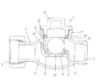
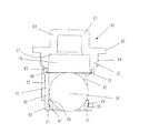
ボールバケットをキャップに対して回転可能に取付け、弁本体とボールバケットとに、弁本体に対するボールバケットの回転方向での位置決めを行ない、且つボールバケットの回転を阻止する位置決め手段を設けることにより、ボールバケットに設けられた水を通すための開口の円周方向での位置が正しく設定され、取り付け中は勿論、取付け後の使用中においてもその位置がずれることがなく、騒音、振動などの発生が防止できる。
位置決め手段は、弁本体の挿入穴内周部とボールバケットの外周部のいずれか一方に形成された突部要素と他方に形成された凹部要素とで構成し、簡易なものとすることができる。そしてボールバケット側に形成された位置決め手段の要素は、ボールバケットの上部から下部に渡って所定の長さに形成することにより、ボールバケットを挿入する際の位置決めがきわめて容易になる。
ボールバケット側に形成された位置決め手段の要素は、突状のリブとして形成し、弁本体側の位置決め手段の要素は、挿入穴の内壁に形成された縦溝として形成し、このように簡単な構成で正確且つ確実にボールバケットの位置決めと回転止めを行うことができる。
Claims (4)
- 弁本体と、該弁本体に形成された挿入穴から該弁本体内に挿入され、前記弁本体に形成された隔壁に設けられた開口部に配置されるボールバケットと、該ボールバケット内に収受されるボールと、前記挿入穴に取付けられるキャップとを備えたボールリフト型逆止弁において、前記ボールバケットは単一の部材で構成され、前記ボールを収受した前記ボールバケットは前記キャップに対して回転可能で軸方向移動不能に取付けられ、前記弁本体と前記ボールバケットとには、前記弁本体に対する前記ボールバケットの回転方向での位置決めを行ない、前記ボールバケットの回転を阻止する位置決め手段が設けられていることを特徴とする、ボールリフト型逆止弁。
- 請求項1記載のボールリフト型逆止弁において、前記位置決め手段は、前記弁本体の挿入穴内周部と前記ボールバケットの外周部のいずれか一方に形成された突部要素と他方に形成された凹部要素とからなることを特徴とする、ボールリフト型逆止弁。
- 請求項2記載のボールリフト型逆止弁において、前記ボールバケット側に形成された位置決め手段の要素は、前記ボールバケットの上部から下部に渡って所定の長さに形成されていることを特徴とする、ボールリフト型逆止弁。
- 請求項3記載のボールリフト型逆止弁において、前記ボールバケット側に形成された位置決め手段の要素は、突状のリブとして形成され、前記弁本体側の位置決め手段の要素は、前記挿入穴の内壁に形成された縦溝であることを特徴とする、前記ボールリフト型逆止弁。
Priority Applications (1)
| Application Number | Priority Date | Filing Date | Title |
|---|---|---|---|
| JP2008035734A JP5090958B2 (ja) | 2008-02-18 | 2008-02-18 | ボールリフト型逆止弁 |
Applications Claiming Priority (1)
| Application Number | Priority Date | Filing Date | Title |
|---|---|---|---|
| JP2008035734A JP5090958B2 (ja) | 2008-02-18 | 2008-02-18 | ボールリフト型逆止弁 |
Publications (3)
| Publication Number | Publication Date |
|---|---|
| JP2009192037A JP2009192037A (ja) | 2009-08-27 |
| JP2009192037A5 JP2009192037A5 (ja) | 2011-03-17 |
| JP5090958B2 true JP5090958B2 (ja) | 2012-12-05 |
Family
ID=41074232
Family Applications (1)
| Application Number | Title | Priority Date | Filing Date |
|---|---|---|---|
| JP2008035734A Active JP5090958B2 (ja) | 2008-02-18 | 2008-02-18 | ボールリフト型逆止弁 |
Country Status (1)
| Country | Link |
|---|---|
| JP (1) | JP5090958B2 (ja) |
Families Citing this family (2)
| Publication number | Priority date | Publication date | Assignee | Title |
|---|---|---|---|---|
| JP5981629B1 (ja) * | 2015-11-20 | 2016-08-31 | 株式会社竹村製作所 | 逆止弁システム |
| KR101683419B1 (ko) * | 2016-04-05 | 2016-12-07 | (주)지오 | 볼 에어 트랩 |
Family Cites Families (3)
| Publication number | Priority date | Publication date | Assignee | Title |
|---|---|---|---|---|
| JPS49129122U (ja) * | 1973-03-03 | 1974-11-06 | ||
| JP5214959B2 (ja) * | 2007-12-17 | 2013-06-19 | 株式会社タブチ | 逆止弁装置 |
| JP5073511B2 (ja) * | 2008-01-18 | 2012-11-14 | 株式会社キッツ | 逆止弁 |
-
2008
- 2008-02-18 JP JP2008035734A patent/JP5090958B2/ja active Active
Also Published As
| Publication number | Publication date |
|---|---|
| JP2009192037A (ja) | 2009-08-27 |
Similar Documents
| Publication | Publication Date | Title |
|---|---|---|
| US7114703B2 (en) | Valve | |
| JP4960448B2 (ja) | 浄水器フィルターアセンブリー | |
| US20160166079A1 (en) | Inflation device for an inflatable mattress | |
| JP5090958B2 (ja) | ボールリフト型逆止弁 | |
| US7644728B2 (en) | Splitter for faucets | |
| JP2009192037A5 (ja) | ||
| JP5266906B2 (ja) | 給油ノズル差込部構造 | |
| JP6442324B2 (ja) | 二重容器 | |
| EP3292901B1 (en) | Drainage system for a fluid filter | |
| JP2008144523A (ja) | ボウルの排水構造 | |
| JP6425234B2 (ja) | 排液コネクタ | |
| JP3087986U (ja) | ガスタンクの開閉装置 | |
| JP3124650U (ja) | 止水型チャック | |
| US9637892B2 (en) | Vertical faucet structure | |
| JP3219781U (ja) | 管内固定構造 | |
| JP2007135891A (ja) | 液体容器の中栓構造 | |
| US20090206022A1 (en) | Drain mechanism and fluid filter including drain mechanism | |
| JP2015124850A (ja) | 手動弁 | |
| JP5024988B2 (ja) | 内視鏡の鉗子栓 | |
| JP7212574B2 (ja) | 通気弁 | |
| JP4397022B2 (ja) | 分岐継手 | |
| CN211738049U (zh) | 一种具有圆柱类手轮的阀门 | |
| JP3127795U (ja) | 逆止弁 | |
| TWM575395U (zh) | Valve stem | |
| JP2008106844A (ja) | ガス栓 |
Legal Events
| Date | Code | Title | Description |
|---|---|---|---|
| A521 | Request for written amendment filed |
Free format text: JAPANESE INTERMEDIATE CODE: A523 Effective date: 20110128 |
|
| A621 | Written request for application examination |
Free format text: JAPANESE INTERMEDIATE CODE: A621 Effective date: 20110128 |
|
| A977 | Report on retrieval |
Free format text: JAPANESE INTERMEDIATE CODE: A971007 Effective date: 20120514 |
|
| A131 | Notification of reasons for refusal |
Free format text: JAPANESE INTERMEDIATE CODE: A131 Effective date: 20120522 |
|
| A521 | Request for written amendment filed |
Free format text: JAPANESE INTERMEDIATE CODE: A523 Effective date: 20120717 |
|
| TRDD | Decision of grant or rejection written | ||
| A01 | Written decision to grant a patent or to grant a registration (utility model) |
Free format text: JAPANESE INTERMEDIATE CODE: A01 Effective date: 20120814 |
|
| A01 | Written decision to grant a patent or to grant a registration (utility model) |
Free format text: JAPANESE INTERMEDIATE CODE: A01 |
|
| A61 | First payment of annual fees (during grant procedure) |
Free format text: JAPANESE INTERMEDIATE CODE: A61 Effective date: 20120913 |
|
| FPAY | Renewal fee payment (event date is renewal date of database) |
Free format text: PAYMENT UNTIL: 20150921 Year of fee payment: 3 |
|
| R150 | Certificate of patent or registration of utility model |
Ref document number: 5090958 Country of ref document: JP Free format text: JAPANESE INTERMEDIATE CODE: R150 Free format text: JAPANESE INTERMEDIATE CODE: R150 |
|
| R250 | Receipt of annual fees |
Free format text: JAPANESE INTERMEDIATE CODE: R250 |
|
| R250 | Receipt of annual fees |
Free format text: JAPANESE INTERMEDIATE CODE: R250 |
|
| R250 | Receipt of annual fees |
Free format text: JAPANESE INTERMEDIATE CODE: R250 |
|
| R250 | Receipt of annual fees |
Free format text: JAPANESE INTERMEDIATE CODE: R250 |
|
| R250 | Receipt of annual fees |
Free format text: JAPANESE INTERMEDIATE CODE: R250 |
|
| R250 | Receipt of annual fees |
Free format text: JAPANESE INTERMEDIATE CODE: R250 |
|
| R250 | Receipt of annual fees |
Free format text: JAPANESE INTERMEDIATE CODE: R250 |
|
| R250 | Receipt of annual fees |
Free format text: JAPANESE INTERMEDIATE CODE: R250 |
|
| R250 | Receipt of annual fees |
Free format text: JAPANESE INTERMEDIATE CODE: R250 |
|
| R250 | Receipt of annual fees |
Free format text: JAPANESE INTERMEDIATE CODE: R250 |


