JP5077253B2 - Pallet automatic changer - Google Patents

Pallet automatic changer Download PDF

Info

Publication number
JP5077253B2
JP5077253B2 JP2009019151A JP2009019151A JP5077253B2 JP 5077253 B2 JP5077253 B2 JP 5077253B2 JP 2009019151 A JP2009019151 A JP 2009019151A JP 2009019151 A JP2009019151 A JP 2009019151A JP 5077253 B2 JP5077253 B2 JP 5077253B2
Authority
JP
Japan
Prior art keywords
pallet
fixing
magazine
palette
fixing table
Prior art date
Legal status (The legal status is an assumption and is not a legal conclusion. Google has not performed a legal analysis and makes no representation as to the accuracy of the status listed.)
Active
Application number
JP2009019151A
Other languages
Japanese (ja)
Other versions
JP2010177486A5 (en
JP2010177486A (en
Inventor
保夫 高浪
Current Assignee (The listed assignees may be inaccurate. Google has not performed a legal analysis and makes no representation or warranty as to the accuracy of the list.)
Panasonic Corp
Panasonic Holdings Corp
Original Assignee
Panasonic Corp
Matsushita Electric Industrial Co Ltd
Priority date (The priority date is an assumption and is not a legal conclusion. Google has not performed a legal analysis and makes no representation as to the accuracy of the date listed.)
Filing date
Publication date
Application filed by Panasonic Corp, Matsushita Electric Industrial Co Ltd filed Critical Panasonic Corp
Priority to JP2009019151A priority Critical patent/JP5077253B2/en
Publication of JP2010177486A publication Critical patent/JP2010177486A/en
Publication of JP2010177486A5 publication Critical patent/JP2010177486A5/ja
Application granted granted Critical
Publication of JP5077253B2 publication Critical patent/JP5077253B2/en
Active legal-status Critical Current
Anticipated expiration legal-status Critical

Links

Images

Abstract

<P>PROBLEM TO BE SOLVED: To provide a palette automatic replacement device that shortens a palette replacement time. <P>SOLUTION: The palette automatic replacement device includes a palette positioning mechanism 5 which positions a palette 3 stored in a palette storage chamber 2, a palette fixation table 20 which moves to and away from the palette storage chamber 2 in directions for taking the palette 3 in and out, and a first fixation portion 23 which fixes and swivels the palette 3, the palette 3 being swiveled when replaced between the palette fixation table 20 and palette storage chamber 2 while the palette fixation table 20 is moved. <P>COPYRIGHT: (C)2010,JPO&amp;INPIT

Description

本発明は、ダイボンディング装置等に用いられるダイ供給用のパレットを自動交換するパレット自動交換装置に関するものである。   The present invention relates to an automatic pallet changing apparatus for automatically changing a pallet for supplying a die used in a die bonding apparatus or the like.

ウェハシートから剥ぎ取ったダイを熱圧着等によって基板に実装するダイボンディング装置において、柔軟性を有するウェハシートは不定形であり、そのままでは取り扱いが不便であるため、パレットと呼ばれる環状の剛性部材に装着された状態で使用される。特許文献1にはこのようなパレットを用いたダイボンディング装置の例が開示されており、ここでは、パレット収納マガジンに予め複数のパレットを収納しておき、必要に応じて順次取り出し、ダイの供給位置に装着するように構成されている。パレット収納マガジンとダイ供給位置との間でのパレットの移動は、パレットに係合させたアームを直線移動させることで行い、ダイ供給位置に装着されているパレットをパレット収納マガジンに戻すとともに次に装着したいパレットを取り出してダイ供給位置に装着するというパレット交換作業が行われる。
特開平4−196148号公報
In a die bonding apparatus that mounts a die peeled from a wafer sheet on a substrate by thermocompression bonding or the like, a flexible wafer sheet is indefinite and inconvenient to handle, so an annular rigid member called a pallet is used. Used in the mounted state. Patent Document 1 discloses an example of a die bonding apparatus using such a pallet. Here, a plurality of pallets are stored in advance in a pallet storage magazine, sequentially taken out as necessary, and a die is supplied. It is configured to be mounted in position. The pallet is moved between the pallet storage magazine and the die supply position by linearly moving the arm engaged with the pallet, and the pallet mounted at the die supply position is returned to the pallet storage magazine and then Pallet replacement work is performed in which the pallet to be mounted is taken out and mounted at the die supply position.
Japanese Patent Laid-Open No. 4-196148

パレットの交換は、できるだけ短時間で広い占有領域を要することなく行うのが理想的であるが、アームの直線移動で交換を行う場合、パレットの移動はアームの移動形態に倣うため、交換時間の短縮には直動機構上の制約に伴う限界がある。また、アームの移動のためだけに装置内の限られた領域を直動機構に占有させることは面積生産性やコストの面から問題がある。   Ideally, the pallet should be replaced in as short a time as possible without requiring a large occupied area.However, when exchanging by linear movement of the arm, the movement of the pallet follows the movement form of the arm. There is a limit to shortening due to restrictions on the linear motion mechanism. In addition, it is problematic in terms of area productivity and cost to make the linear motion mechanism occupy a limited area in the apparatus only for the movement of the arm.

そこで本発明は、パレット交換時間の短縮を実現するパレット自動交換装置を提供することを目的とする。   Therefore, an object of the present invention is to provide an automatic pallet changing apparatus that realizes a reduction in pallet changing time.

本発明のパレット自動交換装置は、複数のパレット収納室が鉛直方向に配備されたパレットマガジンと、前記複数のパレット収納室にそれぞれ配備され、パレット収納室に収納されたパレットの側方に位置するパレット位置決め部材と、前記パレット位置決め部材を、前記パレット収納室に収納されたパレットの側部に接触する位置と接触しない位置とに変位させるパレット位置決め部材変位手段と、前記パレットマガジンに対してパレットを出し入れする方向に配置されたパレット固定テーブルと、前記パレット固定テーブルに配備され、パレットの被係合部と係合するパレット係合部材と、前記パレット固定テーブルを前記パレットマガジンに対して接近する方向と離反する方向とに移動させるパレット移動手段と、前記パレット固定テーブルに配備され、前記パレット係合部材を旋回させるパレット旋回手段とを備え、前記パレット係合部材と係合したパレットを旋回および移動させることで前記パレット固定テーブルと前記パレットマガジンとの間でパレットの交換を行う。 The automatic pallet changing apparatus of the present invention is located on the side of a pallet magazine in which a plurality of pallet storage chambers are arranged in the vertical direction and a pallet in each of the plurality of pallet storage chambers and stored in the pallet storage chambers. a pallet positioning member, said pallet positioning member, a pallet positioning member displacing means for displacing into a position where it does not contact with the position in contact with the side portion of the stored in the pallet storage chamber pallets, the pallets to the pallet magazine A pallet fixing table arranged in the direction of taking in and out, a pallet engaging member arranged on the pallet fixing table and engaged with an engaged portion of the pallet, and a direction in which the pallet fixing table approaches the pallet magazine Pallet moving means for moving in a direction away from the pallet; And a pallet turning means for turning the pallet engaging member. The pallet is moved between the pallet fixing table and the pallet magazine by turning and moving the pallet engaged with the pallet engaging member. Exchange.

本発明は、パレットの直線運動の他に旋回運動を追加したことにより、パレットの直線移動距離を短縮することができ、さらに直線運動と旋回運動を同時に行うことでパレット交換に要する時間を短縮することができる。   According to the present invention, the turning movement is added in addition to the linear movement of the pallet, so that the linear movement distance of the pallet can be shortened, and further, the time required for the pallet exchange is shortened by performing the linear movement and the turning movement simultaneously. be able to.

本発明の実施の形態について図面を参照して説明する。図1は本発明の実施の形態におけるパレット自動交換装置の平面図、図2は本発明の実施の形態におけるパレット自動交換装置の側面図、図3は本発明の実施の形態におけるパレット位置決め機構の爪の動きの説明図、図4は本発明の実施の形態における第1のパレット固定部のパレット固定機構を説明図、図5は本発明の実施の形態におけるウェハリングの平面図、図6は本発明の実施の形態におけるパレット回転部の平面図、図7は本発明の実施の形態におけるパレット基部の平面図、図8は本発明の実施の形態におけるパレット基部にパレット回転部を装着した状態であるパレットの平面図、図9は本発明の実施の形態におけるウェハリング固定部材でウェハリングを固定した状態図、図10は本発明の実施の形態におけるパレット基部にパレット回転部を装着した状態図、図11は本発明の実施の形態におけるパレット回転規制機構の説明図、図12は本発明の実施の形態における第2のパレット固定部のパレット固定機構の説明図、図13は本発明の実施の形態における第2のパレット固定部のパレット固定機構の説明図、図14は本発明の実施の形態における第2のパレット固定部のパレット固定機構の説明図、図15は本発明の実施の形態における第2のパレット固定部のパレット固定機構の説明図、図16は本発明の実施の形態におけるパレット自動交換の工程の説明図、図17は本発明の実施の形態におけるパレット自動交換の工程の説明図、図18は本発明の実施の形態におけるパレット自動交換の工程の説明図、図19は本発明の実施の形態におけるパレット自動交換の工程の説明図、図20は本発明の実施の形態におけるパレット自動交換の工程の説明図、図21は本発明の実施の形態におけるトレイを装着したパレットの平面図である。   Embodiments of the present invention will be described with reference to the drawings. 1 is a plan view of an automatic pallet changing apparatus according to an embodiment of the present invention, FIG. 2 is a side view of the automatic pallet changing apparatus according to an embodiment of the present invention, and FIG. 3 is a pallet positioning mechanism according to the embodiment of the present invention. FIG. 4 is an explanatory view of the movement of the claw, FIG. 4 is an explanatory view of the pallet fixing mechanism of the first pallet fixing portion in the embodiment of the present invention, FIG. 5 is a plan view of the wafer ring in the embodiment of the present invention, and FIG. FIG. 7 is a plan view of a pallet base in the embodiment of the present invention, and FIG. 8 is a state in which the pallet rotation unit is mounted on the pallet base in the embodiment of the present invention. 9 is a plan view of the pallet, FIG. 9 is a state diagram in which the wafer ring is fixed by the wafer ring fixing member in the embodiment of the present invention, and FIG. 10 is a pallet base in the embodiment of the present invention. FIG. 11 is an explanatory diagram of a pallet rotation restricting mechanism according to the embodiment of the present invention, and FIG. 12 is an explanatory diagram of the pallet fixing mechanism of the second pallet fixing portion according to the embodiment of the present invention. FIG. 13 is an explanatory diagram of the pallet fixing mechanism of the second pallet fixing portion in the embodiment of the present invention, and FIG. 14 is an explanatory diagram of the pallet fixing mechanism of the second pallet fixing portion in the embodiment of the present invention. FIG. 15 is an explanatory view of a pallet fixing mechanism of the second pallet fixing portion in the embodiment of the present invention, FIG. 16 is an explanatory view of a pallet automatic replacement process in the embodiment of the present invention, and FIG. 17 is an embodiment of the present invention. FIG. 18 is an explanatory diagram of a pallet automatic replacement process in the embodiment of the present invention, and FIG. 19 is a pallet automatic replacement process in the embodiment of the present invention. Illustration of steps of automatic exchange, Figure 20 is an explanatory view of a step of automatic pallet exchange in the embodiment of the present invention, FIG 21 is a plan view of the pallet tray is mounted in the embodiment of the present invention.

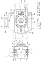
最初にパレット自動交換装置について説明する。図1、図2において、パレットマガジン1は上下方向に区分けされた複数のパレット収納室2を備え、各パレット収納室2にパレット3が一個ずつ収納されている。最上層のパレット収納室2は収納されていたパレット3が取り出されて空室となっている。パレットマガジン1は昇降装置4によって上下に移動可能であり、パレットを取り出すときには取り出したいパレット3を収納したパレット収納室2を所定の高さに位置決めし、取り出したパレット3を収納するときには空室となっているパレット収納室2を所定の高さに位置決めする。   First, an automatic pallet changer will be described. 1 and 2, the pallet magazine 1 includes a plurality of pallet storage chambers 2 divided in the vertical direction, and each pallet storage chamber 2 stores one pallet 3. In the uppermost pallet storage chamber 2, the stored pallet 3 is taken out and becomes an empty chamber. The pallet magazine 1 can be moved up and down by an elevating device 4. When the pallet is taken out, the pallet storage chamber 2 containing the pallet 3 to be taken out is positioned at a predetermined height, and when the pallet 3 taken out is stored, the pallet magazine 1 The pallet storage chamber 2 is positioned at a predetermined height.

パレットマガジン1には収納された各パレット3の位置を横方向(パレット3の出し入れ方向に直交する方向)に規制するパレット位置決め機構5と、パレット3がマガジン内から飛び出さないように前後方向(パレット3の出し入れ方向)に押さえ付けるパレット飛び出し防止機構6が備わっている。   A pallet positioning mechanism 5 that regulates the position of each pallet 3 stored in the pallet magazine 1 in the lateral direction (direction perpendicular to the direction in which the pallet 3 is put in and out), and the front-rear direction so that the pallet 3 does not jump out of the magazine ( A pallet pop-out prevention mechanism 6 that is pressed in the direction in which the pallet 3 is put in and out is provided.

パレット位置決め機構5は、パレットマガジン1に収納された各パレット3の両側面にパレット位置決め部材となる爪7を接触させることで、パレットマガジン1内のパレット3の横方向における位置決めを行う。パレットマガジン1の両側方には鉛直方向に立てられた回転軸8が2つずつ配置されており、各回転軸8にはパレットマガジン1に収納された各パレット3と同じ高さになる位置に爪7が装着されている。爪7は回転軸8に偏心した位置で装着されており、回転軸8の回転によって各パレット3の両側面に接触するようになっている。パレットマガジン1はパレット出し入れ側以外の3つの側面は閉鎖されているが、両側面には爪7がパレット3に接触できる程度の開口9が形成されている。   The pallet positioning mechanism 5 positions the pallet 3 in the pallet magazine 1 in the lateral direction by bringing the claws 7 serving as pallet positioning members into contact with both side surfaces of each pallet 3 stored in the pallet magazine 1. Two rotating shafts 8 are vertically arranged on both sides of the pallet magazine 1, and each rotating shaft 8 is positioned at the same height as each pallet 3 stored in the pallet magazine 1. A nail 7 is attached. The claw 7 is mounted at a position eccentric to the rotary shaft 8, and comes into contact with both side surfaces of each pallet 3 by the rotation of the rotary shaft 8. The pallet magazine 1 is closed on three sides other than the pallet loading / unloading side, but openings 9 are formed on both sides so that the pawl 7 can contact the pallet 3.

パレットマガジン1の上部には回転軸8を回転させる駆動源となるシリンダ10が配置されている。シリンダ10はピストンロッド11を伸縮させることでリンク部12を介して回転軸8を所定の角度だけ回転させる。ピストンロッド11が縮まった状態では爪7はパレット3の両側面と接触し、パレット3の横方向への移動を規制して所定の位置に位置決めする(図3a参照)。これに対しピストンロッド11が伸びた状態では爪7はパレット3の両側面から離れ、パレット3は規制を解かれた状態となる(図3b参照)。この状
態においてパレット3をパレットマガジン1から取り出すことが可能であり、またパレット3をパレットマガジン1に収納することが可能である。
A cylinder 10 serving as a drive source for rotating the rotary shaft 8 is disposed on the pallet magazine 1. The cylinder 10 expands and contracts the piston rod 11 to rotate the rotating shaft 8 through a link portion 12 by a predetermined angle. When the piston rod 11 is contracted, the claw 7 comes into contact with both side surfaces of the pallet 3 and restricts the movement of the pallet 3 in the lateral direction to be positioned at a predetermined position (see FIG. 3a). On the other hand, when the piston rod 11 is extended, the claw 7 is separated from both side surfaces of the pallet 3, and the pallet 3 is in a state where the regulation is released (see FIG. 3b). In this state, the pallet 3 can be taken out from the pallet magazine 1, and the pallet 3 can be stored in the pallet magazine 1.

パレット飛び出し防止機構6はパレットマガジン1に収納された各パレット3の端部に係合部材13を接触させることで前後方向における移動を規制し、マガジン内に固定して飛び出しを防止する。係合部材13は鉛直に立てられた棒状の部材であり、回転軸14を中心として回動し、パレットマガジン1のパレット出し入れ側の前面で各パレット3の端部に接触する位置と、この前面からパレットマガジン1の両側面側に退避した位置とに移動する。パレットマガジン1の下部に係合部材13を移動させる駆動源となるシリンダ機構15が配置されている。シリンダ機構15の直線運動は図示しないリンク機構を介して係合部材13の回動に変換される。   The pallet pop-out preventing mechanism 6 regulates the movement in the front-rear direction by bringing the engaging member 13 into contact with the end of each pallet 3 stored in the pallet magazine 1 and fixes it in the magazine to prevent the pop-out. The engaging member 13 is a vertically-arranged rod-like member that rotates around the rotation shaft 14 and contacts the end of each pallet 3 on the front surface of the pallet magazine 1 on the pallet loading / unloading side. To the position retracted to both side surfaces of the pallet magazine 1. A cylinder mechanism 15 serving as a drive source for moving the engagement member 13 is disposed below the pallet magazine 1. The linear motion of the cylinder mechanism 15 is converted into rotation of the engagement member 13 via a link mechanism (not shown).

パレット固定テーブル20はパレットマガジン1から取り出したパレット3を固定する場であり、パレットマガジン1のパレット出し入れ側に配置されている。パレット固定テーブル20は2つの直動テーブル21、22によって水平移動可能であり、パレット3を固定するためのパレット固定部23、24を備えている。第1の直動テーブル21はボールねじ機構25によってパレット固定テーブル20をパレット3の出し入れ方向に移動させる。第2の直動テーブル22はボールねじ機構26によってパレット固定テーブル20をパレット3の出し入れ方向と直交する方向に移動させる。   The pallet fixing table 20 is a place for fixing the pallet 3 taken out from the pallet magazine 1 and is arranged on the pallet magazine insertion / removal side. The pallet fixing table 20 can be moved horizontally by two linear motion tables 21 and 22, and includes pallet fixing portions 23 and 24 for fixing the pallet 3. The first linear motion table 21 moves the pallet fixing table 20 in the direction in which the pallet 3 is put in and out by the ball screw mechanism 25. The second linear motion table 22 moves the pallet fixing table 20 in a direction orthogonal to the direction in and out of the pallet 3 by the ball screw mechanism 26.

第1のパレット固定部23は、パレット固定テーブル20の上部であってパレットマガジン1に近い側に水平旋回可能に配置され、パレット3と係合して固定するパレット係合部材である。第1のパレット固定部23はパレット3の端部に水平方向に並設されている2つの突起部16を挿嵌する2つの陥没部17を備えている。第1のパレット固定部23はパレット固定テーブル20に回転軸27によって枢支されており、モータ28を駆動源として水平に旋回することで向きを変えることが可能である。   The first pallet fixing portion 23 is a pallet engaging member that is disposed on the upper side of the pallet fixing table 20 and close to the pallet magazine 1 so as to be horizontally rotatable, and engages and fixes the pallet 3. The first pallet fixing portion 23 includes two depressed portions 17 into which two projecting portions 16 that are juxtaposed in the horizontal direction at the end of the pallet 3 are inserted. The first pallet fixing part 23 is pivotally supported on the pallet fixing table 20 by a rotating shaft 27, and can be changed in direction by turning horizontally using a motor 28 as a drive source.

第2のパレット固定部24はパレット固定テーブル20の上部であってパレットマガジン1から遠い側に配置されている。第2のパレット固定部24はパレット3の第1のパレット固定部23によって固定された側の反対側を固定する。パレットマガジン1から取り出されたパレット3は、第1のパレット固定部23と第2のパレット固定部24によって前後側を固定されることでパレット固定テーブル20の所定の位置に水平に固定される。   The second pallet fixing part 24 is arranged on the upper side of the pallet fixing table 20 and on the side far from the pallet magazine 1. The second pallet fixing part 24 fixes the side opposite to the side fixed by the first pallet fixing part 23 of the pallet 3. The pallet 3 taken out from the pallet magazine 1 is horizontally fixed at a predetermined position of the pallet fixing table 20 by fixing the front and rear sides by the first pallet fixing part 23 and the second pallet fixing part 24.

ピックアップ装置30とエジェクタ装置31はパレット3から電子部品32を取り出す機能を有する。パレット3には中央部に上下に貫通する空間が形成されており、この空間の上方にウェハシート33に貼り付けられた電子部品32が位置している。パレット固定テーブル20の移動によって所定のピックアップ位置に位置決めされた電子部品32は、下方からエジェクタ装置31によって突き上げられ、上方からピックアップ装置30のノズル34によって吸着されることでパレット3からピックアップされる。   The pickup device 30 and the ejector device 31 have a function of taking out the electronic component 32 from the pallet 3. A space penetrating vertically is formed at the center of the pallet 3, and an electronic component 32 attached to the wafer sheet 33 is located above the space. The electronic component 32 positioned at a predetermined pickup position by the movement of the pallet fixing table 20 is pushed up by the ejector device 31 from below and is picked up from the pallet 3 by being attracted by the nozzle 34 of the pickup device 30 from above.

カメラ35はピックアップ位置に位置決めされた電子部品32を撮像する。撮像によって得られた電子部品32の画像データは電子部品32を基板36に搭載する際に用いられる。電子部品32の向きが傾いている場合にはノズル34の回転によって補正し、位置ずれについては基板36を支持する基板テーブル37を移動することで補正する。   The camera 35 images the electronic component 32 positioned at the pickup position. Image data of the electronic component 32 obtained by imaging is used when the electronic component 32 is mounted on the substrate 36. When the direction of the electronic component 32 is inclined, it is corrected by the rotation of the nozzle 34, and the positional deviation is corrected by moving the substrate table 37 that supports the substrate 36.

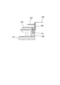
次に第1のパレット固定部23のパレット固定機構について説明する。図4に示すように、第1のパレット固定部材23はパレット3に配備された突起部16を陥没部17に挿入させてパレット3を固定する。突起部16はパレット3の端部から水平に突出しており、先端方向に向けて縮径する錐体状の部位(錐体部)40が形成されている。錐体部40の先には錐体部40の最も先端側の細い部分よりさらに小径の部位41が形成され、その
先には小径部位41より大径の部位42が形成されている。
Next, the pallet fixing mechanism of the first pallet fixing part 23 will be described. As shown in FIG. 4, the first pallet fixing member 23 fixes the pallet 3 by inserting the protrusions 16 provided on the pallet 3 into the depressions 17. The protrusion 16 protrudes horizontally from the end of the pallet 3 and is formed with a cone-shaped portion (cone portion) 40 whose diameter decreases toward the tip. A portion 41 having a smaller diameter than the narrowest portion on the most distal end side of the cone portion 40 is formed at the tip of the cone portion 40, and a portion 42 having a larger diameter than the small diameter portion 41 is formed at the tip.

第1のパレット固定部23の陥没部17には錐体部40の外周面と同形の内周面43が形成されている。内周面43の内側の空間は大径側が外部に開口している。内周面43のさらに奥には突起部16の挿入方向に移動可能な係止部材44が配置されている。係止部材44は中空であり、被係合部材となる突起部16の大径部位42が中空部に挿入される。係止部材44には大径部位42の外周と係合する複数の係合子45が配備されている。陥没部17の奥側には突起部16の挿入方向に縮径するテーパ面46が形成されている。大径部位42にはテーパ面46とは反対の傾斜をなすテーパ面47が形成されている。   An inner peripheral surface 43 having the same shape as the outer peripheral surface of the cone portion 40 is formed in the depressed portion 17 of the first pallet fixing portion 23. The space inside the inner peripheral surface 43 is open to the outside on the large diameter side. A locking member 44 that is movable in the insertion direction of the protruding portion 16 is disposed further to the inner peripheral surface 43. The locking member 44 is hollow, and the large-diameter portion 42 of the protrusion 16 that becomes the engaged member is inserted into the hollow portion. The engaging member 44 is provided with a plurality of engaging elements 45 that engage with the outer periphery of the large-diameter portion 42. On the back side of the depressed portion 17, a tapered surface 46 that is reduced in diameter in the insertion direction of the protrusion 16 is formed. The large diameter portion 42 is formed with a tapered surface 47 having an inclination opposite to the tapered surface 46.

図4(b)に示すように、大径部位42を挿入した係止部材44を陥没部17の奥側に移動させると、テーパ面46に接触した係合子45が内側に移動して大径部位42のテーパ面47に接触し、大径部位42を係止部材44の奥側に押し付ける働きを担う。これにより、錐体部40の外周面と第1のパレット固定部23の内周面43が完全に密着し、パレット3は第1のパレット固定部23に強固に固定される。   As shown in FIG. 4B, when the locking member 44 with the large-diameter portion 42 inserted is moved to the back side of the recessed portion 17, the engaging element 45 that contacts the tapered surface 46 moves inward to increase the large diameter. It contacts the tapered surface 47 of the part 42 and plays a role of pressing the large-diameter part 42 against the back side of the locking member 44. Thereby, the outer peripheral surface of the cone part 40 and the inner peripheral surface 43 of the first pallet fixing part 23 are completely adhered, and the pallet 3 is firmly fixed to the first pallet fixing part 23.

係止部材44はピストンロッド48と接続されており、ピストンロッド48を縮めたときにパレット3を固定し、ピストンロッド48を伸ばしたときにパレット3の固定を解除する。またピストンロッド48を伸ばしたときに陥没部17に突起部16を挿入することができる。   The locking member 44 is connected to the piston rod 48 and fixes the pallet 3 when the piston rod 48 is contracted, and releases the pallet 3 when the piston rod 48 is extended. Further, when the piston rod 48 is extended, the protruding portion 16 can be inserted into the depressed portion 17.

次にパレット3の構造について説明する。パレット3は、ウェハリング50(図5参照)とパレット基部51(図6参照)とパレット回転部52(図7参照)とで構成されている。ウェハリング50は環状の剛体のリングフレーム53で柔軟性を有するウェハシート54を保持したものである。ウェハシート54は粘着性を有する表面に複数の電子部品32に個片化された半導体ウェハが貼り付けられている。ウェハリング50はパレット回転部52の上に固定され、パレット回転部52はパレット基部51の上にパレット基部51に対して回転自在に装着される。   Next, the structure of the pallet 3 will be described. The pallet 3 includes a wafer ring 50 (see FIG. 5), a pallet base 51 (see FIG. 6), and a pallet rotating unit 52 (see FIG. 7). The wafer ring 50 is an annular rigid ring frame 53 that holds a flexible wafer sheet 54. The wafer sheet 54 is affixed with a semiconductor wafer separated into a plurality of electronic components 32 on an adhesive surface. The wafer ring 50 is fixed on the pallet rotating part 52, and the pallet rotating part 52 is mounted on the pallet base part 51 so as to be rotatable with respect to the pallet base part 51.

パレット基部51の端部には前記の突起部16が配置され、これと対向する側には切欠部49が形成されている。パレット基部51は、突起部16が第1のパレット固定部23と係合し、切欠部49が第2のパレット固定部24と係合することでパレット固定テーブル20に固定される。   The projection 16 is disposed at the end of the pallet base 51, and a notch 49 is formed on the opposite side. The pallet base 51 is fixed to the pallet fixing table 20 by the protrusions 16 engaging the first pallet fixing part 23 and the notches 49 engaging the second pallet fixing part 24.

パレット回転部52の上面にはリングフレーム53の中空部より小径のリング部55が配置され、リング部55の外側に4つのウェハリング固定部材56が等間隔で配置されている。リング部55の内側は上下に貫通する空間となっている。ウェハリング固定部材56は指掛け部57とストッパ58からなり、軸59によってパレット回転部52に枢支されている。ストッパ58は軸59よりリング部55に近いところを軸59を中心にパレット回転部52と平行に回動する。ウェハリング50はウェハシート54がリング部55に接触するようにパレット回転部52に重ねられ、ウェハリング固定部材56によってリングフレーム53が固定される(図8、図9参照)。このときリングフレーム53はリング部55の上端より少し下がった位置まで押し下げられるので、リングフレーム53の内側でウェハシート54が延展する。これによりウェハシート54に貼着されている電子部品32の間隔が広がるので、ピックアップのときに隣の電子部品32との干渉を避けることができる。   A ring portion 55 having a smaller diameter than the hollow portion of the ring frame 53 is disposed on the top surface of the pallet rotating portion 52, and four wafer ring fixing members 56 are disposed at equal intervals outside the ring portion 55. The inside of the ring portion 55 is a space that penetrates vertically. The wafer ring fixing member 56 includes a finger hook portion 57 and a stopper 58, and is pivotally supported on the pallet rotating portion 52 by a shaft 59. The stopper 58 rotates in parallel with the pallet rotating portion 52 around the shaft 59 near the ring portion 55 from the shaft 59. The wafer ring 50 is stacked on the pallet rotating unit 52 so that the wafer sheet 54 contacts the ring unit 55, and the ring frame 53 is fixed by the wafer ring fixing member 56 (see FIGS. 8 and 9). At this time, the ring frame 53 is pushed down to a position slightly lower than the upper end of the ring portion 55, so that the wafer sheet 54 extends inside the ring frame 53. As a result, the interval between the electronic components 32 adhered to the wafer sheet 54 is widened, so that it is possible to avoid interference with the adjacent electronic component 32 during pickup.

パレット基部51の中央は上下に貫通する空間となっている。この空間の周囲に3つのローラ60が等間隔で配置されている。パレット回転部52のリング部55の外周にはローラ60の外周と係合する溝が形成されたローラ受け部61が配置されている(図10参
照)。ローラ受け部61に3つのローラ60が係合することによってパレット回転部52はパレット基部51の上に若干のクリアランスをもって装着されている。パレット回転部52は3つのローラ60のみによって支持されているだけであり、パレット基部51に対して回転自在である。
The center of the pallet base 51 is a space penetrating vertically. Around this space, three rollers 60 are arranged at equal intervals. On the outer periphery of the ring portion 55 of the pallet rotating portion 52, a roller receiving portion 61 having a groove that engages with the outer periphery of the roller 60 is disposed (see FIG. 10). The pallet rotating part 52 is mounted on the pallet base part 51 with a slight clearance by engaging the three rollers 60 with the roller receiving part 61. The pallet rotating part 52 is only supported by the three rollers 60 and is rotatable with respect to the pallet base part 51.

次にパレット回転規制機構について図11を参照して説明する。パレット基部51にはローラ受け部61の内周側に位置する係合部材62が配置されている。係合部材62は圧縮バネ63の弾性力によってローラ受け部61の内周面に押し当てられている。係合部材62にはローラ受け部61の内周に面する小さな孔64が形成されており、ローラ受け部61の内周面に形成された小さな突起65が孔64の内側に収まっている。この状態では突起65の動きは孔64によって制限されるので、パレット回転部52はパレット基部51に対して回転不可能な状態になる(図11a参照)。   Next, the pallet rotation restricting mechanism will be described with reference to FIG. An engaging member 62 located on the inner peripheral side of the roller receiving portion 61 is disposed on the pallet base portion 51. The engaging member 62 is pressed against the inner peripheral surface of the roller receiving portion 61 by the elastic force of the compression spring 63. A small hole 64 facing the inner periphery of the roller receiving portion 61 is formed in the engaging member 62, and a small protrusion 65 formed on the inner peripheral surface of the roller receiving portion 61 is accommodated inside the hole 64. In this state, the movement of the protrusion 65 is limited by the hole 64, so that the pallet rotating part 52 cannot rotate with respect to the pallet base 51 (see FIG. 11a).

パレット基部51の端部には係合部材62と連結された押し釦66が配置されている。この押し釦66を押すことで係合部材62は圧縮バネ63の弾性力に抗して移動し、ローラ受け部61の内周面から離れ、これによりパレット回転部52はパレット基部51に対して自由に回転することができるようになる(図11b参照)。   A push button 66 connected to the engaging member 62 is disposed at the end of the pallet base 51. When the push button 66 is pressed, the engaging member 62 moves against the elastic force of the compression spring 63 and moves away from the inner peripheral surface of the roller receiving portion 61, so that the pallet rotating portion 52 moves relative to the pallet base portion 51. It will be able to rotate freely (see FIG. 11b).

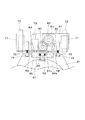
次に第2のパレット固定部24のパレット固定機構について図12、図13、図14を参照して説明する。第2のパレット固定部24はパレット基部51に2箇所設けられた切欠部49と係合する係合部70を備えている。2つの切欠部49は離れた位置に同じ高さに設けられている。係合部70はそれぞれの切欠部49と対応して2箇所同じ高さに設けられている。   Next, the pallet fixing mechanism of the second pallet fixing part 24 will be described with reference to FIGS. 12, 13, and 14. FIG. The second pallet fixing portion 24 includes an engaging portion 70 that engages with a notch portion 49 provided in two places on the pallet base portion 51. The two notches 49 are provided at the same height at positions apart from each other. The engaging portions 70 are provided at the same height at two locations corresponding to the respective cutout portions 49.

第2のパレット固定部24の下面にはスライダ71が配置されている。このスライダ71はパレット固定テーブル20の上面に配置されたレール72に装着されている。第2のパレット固定部24はピストンロッド73の伸縮によってレール72に沿って直線移動する。第2のパレット固定部24は第1のパレット固定部23側に移動したときにパレット基部51を固定し(図12)、反対側に移動したときにパレット基部51の固定を解除する(図13)。   A slider 71 is disposed on the lower surface of the second pallet fixing portion 24. The slider 71 is mounted on a rail 72 disposed on the upper surface of the pallet fixing table 20. The second pallet fixing part 24 moves linearly along the rail 72 by the expansion and contraction of the piston rod 73. The second pallet fixing part 24 fixes the pallet base 51 when it moves to the first pallet fixing part 23 side (FIG. 12), and releases the pallet base 51 when it moves to the opposite side (FIG. 13). ).

図14は係合部70と切欠部49とが係合した状態を側面図で示している。切欠部49には断面円形のピン74が横向きに装着されている。係合部70の先端はピン70を上下に挟むV字型の溝75が形成されており、第2のパレット固定部24が第1のパレット固定部23側に移動したときにV字溝75がピン74と接触するようになっている(図14a)。係合部70は圧縮ばね76によって第2のパレット固定部24から離れる側に付勢されており、接触したそれぞれのピン74をV字溝75の最奥部に押し付けてパレット基部51を水平に固定する(図14b)。   FIG. 14 is a side view showing a state where the engaging portion 70 and the cutout portion 49 are engaged. A pin 74 having a circular cross section is mounted laterally in the notch 49. A V-shaped groove 75 that sandwiches the pin 70 up and down is formed at the tip of the engaging portion 70, and when the second pallet fixing portion 24 moves to the first pallet fixing portion 23 side, the V-shaped groove 75. Is in contact with the pin 74 (FIG. 14a). The engaging portion 70 is urged to the side away from the second pallet fixing portion 24 by the compression spring 76, and the pallet base 51 is horizontally moved by pressing each contacted pin 74 against the innermost portion of the V-shaped groove 75. Fix (Fig. 14b).

次にパレット回転部52を回転させるための機構について説明する。図7においてパレット回転部52には円弧型の従動ギヤ80が備わっている。図12において第2のパレット固定部24には、従動ギヤ80と螺合する駆動ギヤ81と、駆動ギヤ81と螺合する主動ギヤ82が備わっている。第2のパレット固定部24がパレット基部51を固定したときに駆動ギヤ81が従動ギヤ80に係合するようになっている。主動ギヤ82はモータ83によって駆動し、駆動ギヤ81を経て従動ギヤ80に駆動力を伝達する。モータ83の駆動制御によりパレット回転部52の回転角を調整することができる。   Next, a mechanism for rotating the pallet rotating unit 52 will be described. In FIG. 7, the pallet rotating portion 52 is provided with an arc-shaped driven gear 80. In FIG. 12, the second pallet fixing portion 24 includes a drive gear 81 that is screwed with the driven gear 80, and a main drive gear 82 that is screwed with the drive gear 81. The driving gear 81 is engaged with the driven gear 80 when the second pallet fixing part 24 fixes the pallet base part 51. The main driving gear 82 is driven by a motor 83 and transmits a driving force to the driven gear 80 via the driving gear 81. The rotation angle of the pallet rotating unit 52 can be adjusted by driving control of the motor 83.

第2のパレット固定部24にはパレット回転部52の回転角を規制する機構が備わっている。第2のパレット固定部24には駆動ギヤ81を挟んだ位置に一対の光センサ84、85が配置され、パレット回転部52に装着されている遮光プレート86(図7)を検出
するようになっている。パレット回転部52の回転に伴って移動する遮光プレート86が光センサ84、85から発せられる光と干渉するとモータ83の駆動停止によりパレット回転部52の回転が停止する。
The second pallet fixing part 24 is provided with a mechanism for regulating the rotation angle of the pallet rotating part 52. A pair of optical sensors 84 and 85 are disposed in the second pallet fixing portion 24 at a position sandwiching the drive gear 81 so as to detect the light shielding plate 86 (FIG. 7) attached to the pallet rotating portion 52. ing. When the light shielding plate 86 that moves with the rotation of the pallet rotating unit 52 interferes with the light emitted from the optical sensors 84 and 85, the rotation of the pallet rotating unit 52 is stopped by stopping the driving of the motor 83.

さらに第2のパレット固定部24にはパレット基部51の押し釦66を押すための係合解除部材87が備わっている。係合解除部材87は、図15に示すように駆動ギヤ81と従動ギヤ80が互いの刃先が干渉し合うような位置まで第2のパレット固定部24が移動したときに始めて押し釦66に接触するように配置されている。これにより係合部材62による係合が解除されたときには駆動ギヤ81と従動ギヤ80が互いに係合した状態になるので、不意にパレット回転部52が回転してしまうことを防止することができる。   Further, the second pallet fixing part 24 is provided with an engagement releasing member 87 for pressing the push button 66 of the pallet base part 51. As shown in FIG. 15, the disengagement member 87 contacts the push button 66 only when the second pallet fixing portion 24 moves to a position where the driving gear 81 and the driven gear 80 interfere with each other. Are arranged to be. As a result, when the engagement by the engaging member 62 is released, the drive gear 81 and the driven gear 80 are engaged with each other, so that the pallet rotating portion 52 can be prevented from rotating unexpectedly.

次にパレットの自動交換について説明する。ここではパレットマガジン1から取り出したパレット3をパレット固定テーブル20に固定するまでの工程について図面を参照しながら説明を行う。最初に図16に示すように、第1のパレット固定部23を取り出し予定のパレット3の突起部16に相対させる。パレット自動交換装置の動作としては、第1のパレット固定部23の水平旋回(矢印a)とパレット固定テーブル20の水平移動(矢印b、c)によって両者の水平方向の位置合わせを行い、パレットマガジン1の上下移動によって両者の高さ方向に位置合わせを行う。またパレット3は、パレット位置決め機構5によってパレットマガジン1内で固定された状態で位置決めされており、さらにパレット飛び出し防止機構6によってパレットマガジン1内から飛び出さないように前後方向への移動が規制された状態にある。   Next, automatic pallet exchange will be described. Here, a process until the pallet 3 taken out from the pallet magazine 1 is fixed to the pallet fixing table 20 will be described with reference to the drawings. First, as shown in FIG. 16, the first pallet fixing portion 23 is made to be opposed to the projection portion 16 of the pallet 3 to be taken out. As an operation of the automatic pallet changing device, the horizontal rotation of the first pallet fixing portion 23 (arrow a) and the horizontal movement of the pallet fixing table 20 (arrows b and c) are performed to align both in the horizontal direction. Positioning is performed in the height direction of both by moving up and down 1. The pallet 3 is positioned in a state where it is fixed in the pallet magazine 1 by the pallet positioning mechanism 5, and the movement in the front-rear direction is restricted by the pallet pop-out preventing mechanism 6 so as not to jump out from the pallet magazine 1. It is in the state.

そして図17に示すように、パレット固定テーブル20をパレットマガジン1内で固定されたパレット3に向けて水平移動させ、第1のパレット固定部23を2つの突起部16に係合させる。そして図18に示すように、パレット位置決め機構5とパレット飛び出し防止機構6によるパレット3の固定を解除した後にパレット固定テーブル20を水平移動させ、パレットマガジン1からパレット3を取り出す。このときパレット3は一端を第1のパレット固定部23によって固定された片持ちの状態で保持されている。   Then, as shown in FIG. 17, the pallet fixing table 20 is moved horizontally toward the pallet 3 fixed in the pallet magazine 1, and the first pallet fixing portion 23 is engaged with the two protrusions 16. As shown in FIG. 18, the pallet fixing table 20 is moved horizontally after the pallet positioning mechanism 5 and the pallet popping prevention mechanism 6 are fixed, and the pallet 3 is taken out from the pallet magazine 1. At this time, the pallet 3 is held in a cantilever state in which one end is fixed by the first pallet fixing part 23.

パレットマガジン1内からパレット3が完全に取り出されると、第1のパレット固定部23が水平旋回し、図19に示すようにパレット3の向きを180度変換する。この向き変換によってパレット3の他端側(第1のパレット固定部23で固定されていない側)が第2のパレット固定部24と相対する位置関係となる。その後、第2のパレット固定部24が図20に示すようにパレット3側に移動し、パレット3の端部と係合してパレット3を他端側から固定する。同時に駆動ギヤ81が従動ギヤ80と螺合し、パレット回転部52の回転が可能な状態となる。このときパレット3は第1のパレット固定部23と第2のパレット固定部24によって対向する側を両持ちされた状態でパレット固定テーブル20上に固定される。   When the pallet 3 is completely taken out from the pallet magazine 1, the first pallet fixing part 23 rotates horizontally and changes the direction of the pallet 3 by 180 degrees as shown in FIG. By this orientation change, the other end side of the pallet 3 (the side not fixed by the first pallet fixing portion 23) is in a positional relationship facing the second pallet fixing portion 24. Thereafter, the second pallet fixing part 24 moves to the pallet 3 side as shown in FIG. 20, engages with the end of the pallet 3 and fixes the pallet 3 from the other end side. At the same time, the drive gear 81 is screwed with the driven gear 80 so that the pallet rotating part 52 can be rotated. At this time, the pallet 3 is fixed on the pallet fixing table 20 in a state where both the opposite sides are held by the first pallet fixing part 23 and the second pallet fixing part 24.

以上の説明したパレット自動交換装置の利点としては、まず、パレット交換に際して直線移動の他に水平旋回を行うことでパレットの直線移動距離を短縮化することができ、従来の装置に比べて装置全体の簡素化および小型化が実現できることが挙げられる。またパレットの直線移動と旋回を同時に行うことができるので、パレット交換に要する時間を短縮することができる。それから、パレットは複数の突起部を有し、それぞれパレット固定部の陥没部に係合させることで複数の箇所で固定されるので、位置決めにおける精度や再現性がよい。さらに、突起部の錐体部の錐体部の外周面と陥没部に内周面を密着させてパレットを固定することで、移動や旋回中に慣性力や遠心力が作用してもパレットの位置はずれることなく強固に保たれる。   The advantage of the automatic pallet changing apparatus described above is that the linear movement distance of the pallet can be shortened by performing a horizontal turn in addition to the linear movement at the time of pallet exchange. It can be mentioned that simplification and downsizing can be realized. Moreover, since the linear movement and turning of the pallet can be performed at the same time, the time required for the pallet replacement can be shortened. Then, the pallet has a plurality of protrusions, and each is fixed at a plurality of locations by engaging with the recessed portions of the pallet fixing portion, so that the positioning accuracy and reproducibility are good. Furthermore, by fixing the pallet by bringing the inner peripheral surface into close contact with the outer peripheral surface and the recessed portion of the conical portion of the projection, the pallet can be moved even if inertial force or centrifugal force is applied during movement or turning. The position is kept strong without shifting.

また、パレットは片持ちされた状態で移動するため、自重により固定されていない側が
垂下する場合がありうるが、パレット固定テーブル上では両持ちの状態で固定されるので水平に保たれる。両持ちで固定されたパレットはパレット固定テーブルの移動の際にも振動や位置ずれが効果的に抑えられるので、電子部品の位置決め精度が向上することになる。
In addition, since the pallet moves in a cantilevered state, the side that is not fixed by its own weight may hang down. However, since the pallet is fixed in a both-sided state on the pallet fixing table, it is kept horizontal. Since the pallet fixed by both ends can effectively suppress vibration and displacement even when the pallet fixing table is moved, the positioning accuracy of the electronic component is improved.

さらに、パレット収納室2に配備された爪7によってパレット3をパレッマガジン1に対して固定できようにしたことで、パレット収納時の作業性とパレット交換時のパレット3の安定性の両立が可能になった。パレット収納室2は、パレット3の幅より若干幅広に作られており、これによりパレット3とパレットマガジン1の接触抵抗を無くしてパレット収納時の作業性を向上させている。しかしその反面、両者の間の隙間によってパレット3がパレットマガジン1内で遊んでしまい、位置ずれやパレットマガジン1からの脱落などの不具合が生じていた。爪7は、パレット3の両側部に接触する位置と接触しない位置とに変位可能であるので、パレット収納時にはパレット3に接触させないことで作業性が維持され、それ以外の場面では接触させておくことでパレットマガジン1内におけるパレット3の位置や姿勢が安定することになる。   Furthermore, since the pallet 3 can be fixed to the pallet magazine 1 by the claw 7 provided in the pallet storage chamber 2, both workability when storing the pallet and stability of the pallet 3 when replacing the pallet are possible. Became. The pallet storage chamber 2 is made slightly wider than the width of the pallet 3, thereby eliminating contact resistance between the pallet 3 and the pallet magazine 1, thereby improving workability during pallet storage. However, on the other hand, the pallet 3 is idle in the pallet magazine 1 due to the gap between the two, causing problems such as misalignment and dropping from the pallet magazine 1. Since the claw 7 can be displaced between a position where it contacts both sides of the pallet 3 and a position where it does not contact, the operability is maintained by not contacting the pallet 3 when storing the pallet, and it is kept in contact in other situations. As a result, the position and posture of the pallet 3 in the pallet magazine 1 are stabilized.

パレット自動交換装置は、図21に示すように、ウェハシートではなくトレイ90を装着しているパレット91も使用することができる。パレット91は、パレット3と外形を同じくし、さらに同様の突起部92を備えている。矩形のトレイ90は、パレット91の右下部にある位置決め板93に右下の角部を当て、上辺と左辺をそれぞれ寄せ板94、95に当てた状態でパレット91の略中央に固定されている。寄せ板94、95はそれぞれ溝96、97に沿って移動可能であり、図示しない付勢手段であるコイルばねによってそれぞれ下方および右方に付勢されている。トレイ90には格子状に凹部98が形成されており、この凹部98に電子部品99が一個ずつ収納されている。   As shown in FIG. 21, the automatic pallet changing apparatus can also use a pallet 91 on which a tray 90 is mounted instead of a wafer sheet. The pallet 91 has the same outer shape as the pallet 3, and further includes a similar protrusion 92. The rectangular tray 90 is fixed to the approximate center of the pallet 91 with the lower right corner applied to the positioning plate 93 at the lower right of the pallet 91 and the upper side and the left side applied to the side plates 94 and 95, respectively. . The close-up plates 94 and 95 are movable along the grooves 96 and 97, respectively, and are biased downward and rightward by coil springs that are biasing means (not shown). The tray 90 has recesses 98 formed in a lattice shape, and the electronic components 99 are stored in the recesses 98 one by one.

電子部品32がウェハシート54に貼り付けられているパレット3と違い、パレット91では電子部品99は凹部98に置かれているだけなので、パレットマガジン1とパレット91との間に隙間があると突起部16と陥没部17の間に水平方向の位置ずれが生じるため、パレット固定時に振動や衝撃が発生することによって凹部98やトレイ99から飛び出し易い。この場合でも、爪7によってパレット91を固定することで、パレットマガジン1内でパレット91が遊ぶことがなくなり、振動や衝撃の発生を極力抑制することができる。   Unlike the pallet 3 in which the electronic component 32 is attached to the wafer sheet 54, the electronic component 99 is only placed in the recess 98 in the pallet 91, so that if there is a gap between the pallet magazine 1 and the pallet 91, the projection Since a horizontal displacement occurs between the portion 16 and the depressed portion 17, vibrations and impacts are easily generated when the pallet is fixed, so that the portion 16 and the tray 99 are likely to jump out. Even in this case, by fixing the pallet 91 with the claws 7, the pallet 91 is not played in the pallet magazine 1, and the occurrence of vibration and impact can be suppressed as much as possible.

本発明は、パレットの直線運動の他に旋回運動を追加したことにより、パレットの直線移動距離を短縮することができ、さらに直線運動と旋回運動を同時に行うことでパレット交換に要する時間を短縮することができ、殊に複数のパレットを用いてチップの搭載を行うマルチチップボンダ等に有用である。   According to the present invention, the turning movement is added in addition to the linear movement of the pallet, so that the linear movement distance of the pallet can be shortened, and further, the time required for the pallet replacement is reduced by performing the linear movement and the turning movement simultaneously. In particular, it is useful for a multi-chip bonder or the like in which chips are mounted using a plurality of pallets.

本発明の実施の形態におけるパレット自動交換装置の平面図The top view of the pallet automatic exchange apparatus in embodiment of this invention 本発明の実施の形態におけるパレット自動交換装置の側面図Side view of automatic pallet changing apparatus according to an embodiment of the present invention 本発明の実施の形態におけるパレット位置決め機構の爪の動きの説明図Explanatory drawing of the movement of the nail | claw of the pallet positioning mechanism in embodiment of this invention 本発明の実施の形態における第1のパレット固定部のパレット固定機構を説明図Explanatory drawing of the pallet fixing mechanism of the 1st pallet fixing | fixed part in embodiment of this invention 本発明の実施の形態におけるウェハリングの平面図Plan view of wafer ring in the embodiment of the present invention 本発明の実施の形態におけるパレット回転部の平面図The top view of the pallet rotation part in embodiment of this invention 本発明の実施の形態におけるパレット基部の平面図The top view of the pallet base part in embodiment of this invention 本発明の実施の形態におけるパレット基部にパレット回転部を装着した状態であるパレットの平面図The top view of the pallet which is the state which mounted | wore with the pallet rotation part in the pallet base in embodiment of this invention 本発明の実施の形態におけるウェハリング固定部材でウェハリングを固定した状態図The state figure which fixed the wafer ring with the wafer ring fixing member in embodiment of this invention 本発明の実施の形態におけるパレット基部にパレット回転部を装着した状態図The state figure which attached the pallet rotation part to the pallet base in embodiment of this invention 本発明の実施の形態におけるパレット回転規制機構の説明図Explanatory drawing of the pallet rotation regulation mechanism in embodiment of this invention 本発明の実施の形態における第2のパレット固定部のパレット固定機構の説明図Explanatory drawing of the pallet fixing mechanism of the 2nd pallet fixing | fixed part in embodiment of this invention 本発明の実施の形態における第2のパレット固定部のパレット固定機構の説明図Explanatory drawing of the pallet fixing mechanism of the 2nd pallet fixing | fixed part in embodiment of this invention 本発明の実施の形態における第2のパレット固定部のパレット固定機構の説明図Explanatory drawing of the pallet fixing mechanism of the 2nd pallet fixing | fixed part in embodiment of this invention 本発明の実施の形態における第2のパレット固定部のパレット固定機構の説明図Explanatory drawing of the pallet fixing mechanism of the 2nd pallet fixing | fixed part in embodiment of this invention 本発明の実施の形態におけるパレット自動交換の工程の説明図Explanatory drawing of the process of the pallet automatic exchange in embodiment of this invention 本発明の実施の形態におけるパレット自動交換の工程の説明図Explanatory drawing of the process of the pallet automatic exchange in embodiment of this invention 本発明の実施の形態におけるパレット自動交換の工程の説明図Explanatory drawing of the process of the pallet automatic exchange in embodiment of this invention 本発明の実施の形態におけるパレット自動交換の工程の説明図Explanatory drawing of the process of the pallet automatic exchange in embodiment of this invention 本発明の実施の形態におけるパレット自動交換の工程の説明図Explanatory drawing of the process of the pallet automatic exchange in embodiment of this invention 本発明の実施の形態におけるトレイを装着したパレットの平面図The top view of the pallet which attached the tray in embodiment of this invention

1 パレットマガジン
2 パレット収納室
3、91 パレット
7 爪(パレット位置決め部材)
16 突起部
17 陥没部
20 パレット固定テーブル
23 第1のパレット固定部
1 Pallet Magazine 2 Pallet Storage Room 3, 91 Pallet 7 Claw (Pallet Positioning Member)
16 Protruding part 17 Depressed part 20 Pallet fixing table 23 First pallet fixing part

Claims (1)

複数のパレット収納室が鉛直方向に配備されたパレットマガジンと、前記複数のパレット収納室にそれぞれ配備され、パレット収納室に収納されたパレットの側方に位置するパレット位置決め部材と、前記パレット位置決め部材を、前記パレット収納室に収納されたパレットの側部に接触する位置と接触しない位置とに変位させるパレット位置決め部材変位手段と、前記パレットマガジンに対してパレットを出し入れする方向に配置されたパレット固定テーブルと、前記パレット固定テーブルに配備され、パレットの被係合部と係合するパレット係合部材と、前記パレット固定テーブルを前記パレットマガジンに対して接近する方向と離反する方向とに移動させるパレット移動手段と、前記パレット固定テーブルに配備され、前記パレット係合部材を旋回させるパレット旋回手段とを備え、
前記パレット係合部材と係合したパレットを旋回および移動させることで前記パレット固定テーブルと前記パレットマガジンとの間でパレットの交換を行うことを特徴とするパレット自動交換装置。
A pallet magazine in which a plurality of pallet storage chambers are arranged in the vertical direction, a pallet positioning member that is provided in each of the plurality of pallet storage chambers and is located on the side of the pallet stored in the pallet storage chamber, and the pallet positioning member , said pallet and a position in contact with the side portion of the housing pallet in the storage chamber and the pallet positioning member displacing means for displacing the position and not in contact, arranged pallet fixing in the direction of loading and unloading the pallets to the pallet magazine A table, a pallet engaging member that is disposed on the pallet fixing table and engages with an engaged portion of the pallet, and a pallet that moves the pallet fixing table in a direction toward and away from the pallet magazine A moving means and the pallet fixing table disposed on the pallet fixing table; And a pallet pivot means for pivoting the member,
An automatic pallet exchanging apparatus, wherein a pallet is exchanged between the pallet fixing table and the pallet magazine by rotating and moving a pallet engaged with the pallet engaging member.
JP2009019151A 2009-01-30 2009-01-30 Pallet automatic changer Active JP5077253B2 (en)

Priority Applications (1)

Application Number Priority Date Filing Date Title
JP2009019151A JP5077253B2 (en) 2009-01-30 2009-01-30 Pallet automatic changer

Applications Claiming Priority (1)

Application Number Priority Date Filing Date Title
JP2009019151A JP5077253B2 (en) 2009-01-30 2009-01-30 Pallet automatic changer

Publications (3)

Publication Number Publication Date
JP2010177486A JP2010177486A (en) 2010-08-12
JP2010177486A5 JP2010177486A5 (en) 2011-03-10
JP5077253B2 true JP5077253B2 (en) 2012-11-21

Family

ID=42708128

Family Applications (1)

Application Number Title Priority Date Filing Date
JP2009019151A Active JP5077253B2 (en) 2009-01-30 2009-01-30 Pallet automatic changer

Country Status (1)

Country Link
JP (1) JP5077253B2 (en)

Families Citing this family (1)

* Cited by examiner, † Cited by third party
Publication number Priority date Publication date Assignee Title
JP6715591B2 (en) * 2015-11-12 2020-07-01 株式会社Fuji Electronic component mounting machine

Family Cites Families (12)

* Cited by examiner, † Cited by third party
Publication number Priority date Publication date Assignee Title
JPS6176257A (en) * 1984-09-18 1986-04-18 Murata Mach Ltd Work transfer system
JPS63282004A (en) * 1987-05-11 1988-11-18 Kawasaki Steel Corp Article conveying and storing equipment
JPH0795551B2 (en) * 1988-12-07 1995-10-11 松下電器産業株式会社 Chip feeder
GB9006036D0 (en) * 1990-03-16 1990-05-09 Emhart Deutschland Die presentation system for die bonder
JPH06132398A (en) * 1992-10-21 1994-05-13 Fujitsu Ltd Wafer ring fixing device
JPH09190988A (en) * 1996-01-11 1997-07-22 Toshiba Mechatronics Kk Sheet expanding device
JP3693783B2 (en) * 1997-03-21 2005-09-07 大日本スクリーン製造株式会社 Substrate processing equipment
JP2002084096A (en) * 2000-09-08 2002-03-22 Yamaha Motor Co Ltd Tray parts feeder
EP1310986A1 (en) * 2001-11-08 2003-05-14 F &amp; K Delvotec Bondtechnik GmbH Transfer mechanism for a die presentation package
JP4039104B2 (en) * 2002-04-18 2008-01-30 松下電器産業株式会社 Wafer supply device
JP4085995B2 (en) * 2004-03-16 2008-05-14 松下電器産業株式会社 Rotary table mechanism
JP4544173B2 (en) * 2006-02-13 2010-09-15 パナソニック株式会社 Electronic component transfer equipment

Also Published As

Publication number Publication date
JP2010177486A (en) 2010-08-12

Similar Documents

Publication Publication Date Title
JP6040530B2 (en) Handler and inspection equipment
JP4962194B2 (en) Image input module adjustment apparatus and image input module adjustment method
JP2010179420A (en) Industrial robot
JP5303301B2 (en) Industrial robot
JP5022712B2 (en) Component transfer device and surface mounter
JP2006269794A (en) Nozzle exchange device and component-packaging apparatus
JP5077254B2 (en) Automatic pallet changing method
JP5083221B2 (en) Pallet automatic changer
JP6471401B1 (en) Semiconductor wafer test unit
JP5077253B2 (en) Pallet automatic changer
JP6049221B2 (en) Die supply device
JP4905467B2 (en) Pallet automatic changer
JP5083222B2 (en) Pallet automatic changer
JP6840866B2 (en) Work work equipment
JP6040528B2 (en) Handler and inspection equipment
KR20100119753A (en) Chip supply pallet and chip supply apparatus
JP2017052599A (en) Transfer device and control method of transfer device
JP5773490B2 (en) Die push-up operation management system
US20230398698A1 (en) Adsorption nozzle, component transfer apparatus, and attitude control method of adsorption nozzle
JP2008277354A (en) Gripping device
JP2006319281A (en) Arm driving mechanism, packaging apparatus, method for driving arm, and method for packaging
JP2017170582A (en) Transfer device
JP2000114788A (en) Head for placement, device and method for placing part
JP4555130B2 (en) Flat cable support structure and component supply device
JP6040529B2 (en) Handler and inspection equipment

Legal Events

Date Code Title Description
A521 Written amendment

Free format text: JAPANESE INTERMEDIATE CODE: A523

Effective date: 20110125

A621 Written request for application examination

Free format text: JAPANESE INTERMEDIATE CODE: A621

Effective date: 20110125

RD01 Notification of change of attorney

Free format text: JAPANESE INTERMEDIATE CODE: A7421

Effective date: 20110215

A977 Report on retrieval

Free format text: JAPANESE INTERMEDIATE CODE: A971007

Effective date: 20120622

TRDD Decision of grant or rejection written
A01 Written decision to grant a patent or to grant a registration (utility model)

Free format text: JAPANESE INTERMEDIATE CODE: A01

Effective date: 20120731

A01 Written decision to grant a patent or to grant a registration (utility model)

Free format text: JAPANESE INTERMEDIATE CODE: A01

A61 First payment of annual fees (during grant procedure)

Free format text: JAPANESE INTERMEDIATE CODE: A61

Effective date: 20120813

FPAY Renewal fee payment (event date is renewal date of database)

Free format text: PAYMENT UNTIL: 20150907

Year of fee payment: 3

R151 Written notification of patent or utility model registration

Ref document number: 5077253

Country of ref document: JP

Free format text: JAPANESE INTERMEDIATE CODE: R151

FPAY Renewal fee payment (event date is renewal date of database)

Free format text: PAYMENT UNTIL: 20150907

Year of fee payment: 3