JP5050027B2 - Printing apparatus, printing method, and program - Google Patents
Printing apparatus, printing method, and program Download PDFInfo
- Publication number
- JP5050027B2 JP5050027B2 JP2009236581A JP2009236581A JP5050027B2 JP 5050027 B2 JP5050027 B2 JP 5050027B2 JP 2009236581 A JP2009236581 A JP 2009236581A JP 2009236581 A JP2009236581 A JP 2009236581A JP 5050027 B2 JP5050027 B2 JP 5050027B2
- Authority
- JP
- Japan
- Prior art keywords
- printing
- unit
- test
- accepting
- execution instruction
- Prior art date
- Legal status (The legal status is an assumption and is not a legal conclusion. Google has not performed a legal analysis and makes no representation as to the accuracy of the status listed.)
- Expired - Fee Related
Links
Images


Description
本発明は、デジタル複写機等の印刷装置及び印刷方法並びにプログラムに関する。 The present invention relates to a printing apparatus such as a digital copying machine, a printing method, and a program .
近年、デジタル複写機が開発され、普及している。 In recent years, digital copying machines have been developed and are widely used.
デジタル複写機は、画像をCCDで読取り、デジタル信号化し、それに様々な処理を施した後、レーザー信号に変換して電子写真技術で記録媒体上に記録する。 A digital copying machine reads an image with a CCD, converts it into a digital signal, performs various processing on it, converts it into a laser signal, and records it on a recording medium by electrophotographic technology.
またこの画像信号をハードディスクなどの画像メモリに一度貯えてこれを読み出すことで画像形成を行うものも開発されている0これによればスキャナーから画像を一度だけ読み込むだけで複数回繰り返して画像形成ができるため電子ソートなどの機能の実現に有効である。 In addition, an image forming apparatus has been developed in which the image signal is stored once in an image memory such as a hard disk and then read out. 0 According to this, image formation can be repeated multiple times by reading an image once from a scanner. This is effective for realizing functions such as electronic sorting.
またさらにこの画像メモリを備えたことで、1部だけ画像を形成しユーザーがその仕上がりを確認したのち画像形成の継続、または設定モードの変更を行って画像形成を行う試し印刷機能も考案されている。例えば、特許文献1では、試し印刷を部数単位で実行する手法が開示されている。
Furthermore, by providing this image memory, a trial printing function has been devised in which only one copy is formed and the user confirms the finish and then continues image formation or changes the setting mode to form an image. Yes. For example,
しかしながらこの試し印刷機能においては、従来試し印刷を終了して最終的な画像の印字を行うときに何部の印刷を行うかがユーザーの意図に基づく考慮がなされていなかった。 However, in the trial printing function, when the final trial printing is finished and the final image is printed, the number of copies to be printed is not considered based on the user's intention.
例えば1部試し印刷を行った後、ユーザーがそれを良しとして縦続して残りの印刷を行う場合は、試しコピー分も正規な印刷分と考え、残りの継続印刷は設定された置数から試し印刷分の1部を引いた分だけ印刷すればよいはずである。 For example, if the user prints one copy of the test print and then prints the remaining prints as a good print, the test copy is considered to be a regular print and the remaining prints are tested from the set number. It should be printed only by subtracting one copy.
また試し印刷後、何らかのモード変更がなされた場合、試し印刷分はユーザーが所望しない画像形成と判断できるため、継続プリント時には当初設定された置数分だけ画像形成を行う必要がある。 Further, if any mode change is made after the trial printing, it can be determined that the trial printing is an image formation that is not desired by the user, and therefore it is necessary to form an image for the number of images initially set during the continuous printing.
然しながら従来ではここまで試し印刷時に置数について制御したものがないため、ユーザーは状況に応じて一々置数変更をしなければならないという不具合があった。 However, since there has been no control of the number at the time of trial printing so far, there has been a problem that the user has to change the number one by one according to the situation.
本発明は、上述の事情に鑑みて成されたもので、試し印刷で1部の印刷が終了した中断状態で、モード変更の有無を判別し、それに応じて置数を自動的に変更可能とする印刷装置及び印刷方法並びにプログラムを提供することを目的とする。 The present invention has been made in view of the above-described circumstances, and can determine whether or not a mode has been changed in an interrupted state in which one copy of printing has been completed by trial printing, and can automatically change the number accordingly. An object of the present invention is to provide a printing apparatus, a printing method, and a program .
本発明は、下記構成を備えることにより上記課題を解決できるものである。 This invention can solve the said subject by providing the following structure.
(1)印刷手段と、印刷条件を設定する設定手段と、画像データを入力する入力手段と、前記入力手段により入力された画像データと前記設定手段により設定された印刷条件に従って第1の試し印刷を実行するよう前記印刷手段を制御する第1の制御手段と、前記印刷手段が前記第1の試し印刷を実行した後に、前記設定手段により設定された印刷条件を変更させるための変更指示を受け付ける第1の受付手段と、前記印刷手段が前記第1の試し印刷を実行した後に、第2の試し印刷を実行させるための実行指示を受け付ける第2の受付手段と、前記第2の受付手段が前記実行指示を受け付けた場合に、前記入力手段により入力された画像データと前記変更指示に応じて変更された印刷条件に従って前記第2の試し印刷を実行するよう前記印刷手段を制御する第2の制御手段とを有し、前記第2の受付手段は、表示部に表示される所定の表示要素を介して前記実行指示を受け付け、前記印刷手段が前記第1の試し印刷を実行した後において、前記第1の受付手段が前記変更指示を受け付ける前には、前記実行指示を受け付けられるように前記所定の表示要素を表示せず、前記第1の受付手段が前記変更指示を受け付けた後には、前記実行指示を受け付けられるように前記所定の表示要素を表示することを特徴とする印刷装置。
(2)印刷ステップと、印刷条件を設定する設定ステップと、画像データを入力する入力ステップと、前記入力ステップにより入力された画像データと前記設定ステップにより設定された印刷条件に従って第1の試し印刷を実行するよう前記印刷ステップを制御する第1の制御ステップと、前記印刷ステップが前記第1の試し印刷を実行した後に、前記設定ステップにより設定された印刷条件を変更させるための変更指示を受け付ける第1の受付ステップと、前記印刷ステップが前記第1の試し印刷を実行した後に、第2の試し印刷を実行させるための実行指示を受け付ける第2の受付ステップと、前記第2の受付ステップが前記実行指示を受け付けた場合に、前記入力ステップにより入力された画像データと前記変更指示に応じて変更された印刷条件に従って前記第2の試し印刷を実行するよう前記印刷ステップを制御する第2の制御ステップとを含み、前記第2の受付ステップは、表示部に表示される所定の表示要素を介して前記実行指示を受け付け、前記印刷ステップが前記第1の試し印刷を実行した後において、前記第1の受付ステップが前記変更指示を受け付ける前には、前記実行指示を受け付けられるように前記所定の表示要素を表示せず、前記第1の受付ステップが前記変更指示を受け付けた後には、前記実行指示を受け付けられるように前記所定の表示要素を表示することを特徴とする印刷方法。
(3)前項(2)に記載の印刷方法をコンピュータに実行させるためのプログラム。
(1) Printing means, setting means for setting printing conditions, input means for inputting image data, first test printing according to image data input by the input means and printing conditions set by the setting means And a first control unit that controls the printing unit to execute, and after the printing unit executes the first test printing, a change instruction for changing the printing condition set by the setting unit is received. First receiving means, second receiving means for receiving an execution instruction for executing second test printing after the printing means has executed the first test printing, and the second receiving means When the execution instruction is received, the marking is performed so that the second test printing is executed in accordance with the image data input by the input unit and the printing condition changed according to the change instruction. And a second control means for controlling the means, the second reception unit receives the execution instruction through the predetermined display element displayed on the display unit, the printing unit is the first trial After executing printing, before the first receiving unit receives the change instruction , the first receiving unit does not display the predetermined display element so that the execution instruction can be received. After receiving a change instruction, the printing apparatus displays the predetermined display element so as to receive the execution instruction .
(2) A printing step, a setting step for setting printing conditions, an input step for inputting image data, first test printing according to the image data input in the input step and the printing conditions set in the setting step A first control step for controlling the printing step so as to execute, and a change instruction for changing the printing condition set in the setting step after the printing step has executed the first test printing. A first accepting step; a second accepting step for accepting an execution instruction for executing a second test print after the print step performs the first test print; and the second accepting step. When the execution instruction is accepted, it is changed according to the image data input in the input step and the change instruction. And a second control step of controlling the printing step so as to perform the second test print according to the printing conditions, the second receiving step, the via predetermined display element displayed on the display unit receiving an instruction to execute, after the said printing step executes the first test print, the before the first receiving step receives the change instruction, the predetermined display to be accepted the execution instruction An element is not displayed, and after the first receiving step receives the change instruction, the predetermined display element is displayed so that the execution instruction can be received .
(3) A program for causing a computer to execute the printing method described in (2) above .
本発明では、上述の状況に鑑み、試し印刷で部数1部の印刷が終了した中断状態でモード変更の有無を判別し、それに応じて置数を自動的に変更するようにしたものである。 In the present invention, in view of the above-described situation, whether or not there is a mode change is determined in a suspended state in which printing of one copy has been completed by trial printing, and the number of copies is automatically changed accordingly.
すなわち試し印刷での上記中断状態で置数変更がされた場合には、その直後の試し印刷解除後の縦続プリントではその置数分だけ残り分の印字を行い、置数以外のモード変更がされた場合は設定されている置数分だけ残り分の印字を行い、モード変更が一切されなかった場合は、設定されている置数から1を減算した分だけの置数に基づいて残り分の印字を行い、さらに試し印刷が設定されている間の試し印刷は常に1部のみとするが、設定されている置数はそのまま保持するようにしたことで、ユーザーが望む置数分だけの印字結果を特に置数設定の変更なしに提供することができ、その効果は大きいと思料する。 In other words, when the number of places is changed in the above-mentioned interruption state in trial printing, the remaining prints are printed for the number of places in the cascade print after the release of trial printing immediately after that, and the mode other than the number of places is changed. If there is no change in the mode, the remaining number is printed based on the number of digits that is obtained by subtracting 1 from the set number. While printing is performed and only one copy is always printed while the test print is set, the set number is kept as it is, so only the number of copies desired by the user can be printed. I think that the result can be provided without changing the numerical setting, and the effect is great.
以下に本発明の一実施の形態を説明する。 An embodiment of the present invention will be described below.
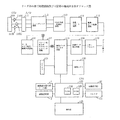
図1は、本発明に係るデジタル複写機としての画像形成装置の要部構成側断面図、図2は、リーダ部の信号処理回路及び主要部の構成例を示すブロック図、図3は、操作部123の詳細説明図、図4は、画像の読み出し方法の例を示す説明図、図5は、画像の記憶方法の例を示す説明図、図6は、操作部123の制御タスクに関するフローチャート、図7は、操作部123のアイドル状態における制御のうち、試しコピーに関するフローチャート、図8は、コピーシーケンスタスクでの制御における本発明に係るフローチャート、図9は、試しコピー中間状態制御動作を示すフローチャート、図10は、試しコピー選択表示画面、図11は、試しコピーモードON表示画面、図12は、試しコピー中表示画面、図13は、設定変更選択画面、図14は、再設定画面、図15は、再設定後の試しコピー表示画面である。
FIG. 1 is a side sectional view of a main part of an image forming apparatus as a digital copying machine according to the present invention, FIG. 2 is a block diagram showing a configuration example of a signal processing circuit and a main part of a reader unit, and FIG. 4 is an explanatory diagram illustrating an example of an image reading method, FIG. 5 is an explanatory diagram illustrating an example of an image storage method, and FIG. 6 is a flowchart regarding a control task of the
以下、図面を参照して説明する。 Hereinafter, description will be given with reference to the drawings.
図1は、リーダ部1およびプリンタ部2の構成を主として示す断面図である。構成および動作について説明する。
FIG. 1 is a cross-sectional view mainly showing the configuration of the
原稿給送装置101上に積載された原稿は、1枚ずつ順次原稿台ガラス面102上に搬送される。原稿が原稿台ガラス面102の所定位置へ搬送されると、スキャナー部のランプ103が点灯、且つスキャナー・ユニット104が移動して原稿を照射する。原稿からの反射光は、ミラー105、106、107、及びレンズ108を介してCCDイメージ・センサー部109(以下CCDと称する)に入力される。
Documents stacked on the
図2は、上記のリーダ部1の信号処理構成を示す回路ブロック図であり、以下、構成および動作について説明する。
FIG. 2 is a circuit block diagram showing a signal processing configuration of the
図2において、CCD109に照射された原稿の反射光は、ここで光電変換され、レッド、グリーン、ブルー(R、G、B)の各色の電気信号に変換される。CCD109からのカラー情報は、次の増幅器110R,110G,110BでA/D変換器111の入力信号レベルに合わせて増幅される。A/D変換器111からの出力信号は、シェーディング回路112に入力され、ここでランプ103の配光ムラや、CCD109の感度ムラが補正される。シェーディング回路112からの信号は、Y信号生成・色検出回路113及び外部I/F切り替え回路に入力される。
In FIG. 2, the reflected light of the original irradiated to the
Y信号生成・色検出回路113は、シェーディング回路112からの信号を下記の式で演算を行い、Y信号を得る。
Y=0.3R+0.6G+0.1B
さらに、R、G、Bの信号から7つの色に分離し、各色に対する信号を出力する色検出回路を有する。Y信号生成・色検出回路113からの出力信号は、変倍・リピート回路114に入力される。スキャナー・ユニット104の走査スピードにより副走査方向の変倍を、変倍・リピート回路114により主走査方向の変倍を行う。また変倍・リピート回路114により複数の同一画像を出力することが可能である。輪郭・エッジ強調回路115は、変倍・リピート回路114からの信号の高周波成分を強調することによりエッジ強調および輪郭情報を得る。輪郭・エッジ強調回路115からの信号は、マーカエリア判定・輪郭生成回路116とパターン化・太らせ・マスキング・トリミング回路117に入力される。
The Y signal generation /
Y = 0.3R + 0.6G + 0.1B
Furthermore, a color detection circuit that separates the R, G, and B signals into seven colors and outputs a signal for each color is provided. An output signal from the Y signal generation /
マーカエリア判定・輪郭生成回路116は、原稿上の指定された色のマーカペンで書かれた部分を読みとりマーカの輪郭情報を生成し、次のパターン化・太らせ・マスキング・トリミング回路117で、この輪郭情報から太らせやマスキングやトリミングを行う。また、Y信号生成・色検出回路113からの色検出信号によりパターン化を行う。
A marker area determination /
パターン化・太らせ・マスキング・トリミング回路117からの出力信号は、プリンタ部2に出力する場合は、後述する画像データセレクタ回路118により選択され、レーザードライバ119に入力され、処理された信号をレーザー駆動するための信号に変換する。レーザードライバ119の出力信号は、プリンタ部2に入力され可視像として画像形成が行われる。
When the output signal from the patterning / thickening / masking /
<画像メモリ120の説明>
図2において、画像メモリ120は、画像データセレクタ回路118により送られた画像データをCPU122の指示により画像メモリ120の指定位置に後述する方法で、記憶及び読み出しを行い、回転処理し、画像をメモリ上で合成する機能を有している。
<Description of
In FIG. 2, an
CPU122はリーダ部1を制御するもので、制御プログラム、エラー処理プログラムなどを記憶するROM124と各種プログラムのワークエリアなどのために利用されるRAM125と各種タイマー制御部等から構成される。操作部123は、リーダ部1の画像処理に対する画像編集内容、コピー枚数等の画像動作を指示する各種キー群と、操作時の内容を表示する表示部等を有している。
The
図3は、本実施例の操作部123の詳細を示したものである。この操作部123には、各種キーと、液晶表示装置からなるドットマトリックスで構成される液晶表示部301とが配置されている。
FIG. 3 shows details of the
液晶表示部301は、装置の状態、コピー枚数、倍率、選択用紙及び各種操作画面を表示し、コントロールキーにより操作される。
The liquid
また、スタートキー303は、コピーをスタートする為のキーであり、復帰キー(リセットキー)304は設定モードを標準状態に復帰するためのキーである。 またキー群305は、コピー枚数、ズーム倍率等を入力させる0〜9までのテンキーとその入力をクリアするためのクリアキーである。濃度キー306は濃度をアップダウンするためのキーであり、これにより調整される濃度は、表示部307に表示される。キー308は自動濃度調整機能をON/OFFするためのキーとその表示部であり、キー309は給紙段及びオート用紙選択を選択するキーで、この選択状態は、前記液晶表示部301に表示される。キー311は等倍、定形縮小/拡大を設定するキーである。またキー310はオート変倍モードを設定する為のキーで、この選択状態は液晶表示部301にも表示される。
A
図4、図5を用いて画像の記憶方法、読み出し方法について説明する。 An image storing method and a reading method will be described with reference to FIGS.
図4の(1)は、画像メモリの1つの記憶容量を示したもので、本実施例では、A3サイズの記憶ができるもので、縦4661×横6596ビットで構成される。この記憶領域が図5に示すように画像レイアウト領域1つと画像記憶領域として、100枚分の画像が記憶できるように構成されている。続いて図4(2)を用いて原稿画像を画像メモリに記憶する場合の例を示したものである。(2)aのように置かれた原稿は、図に示すように矢印の方向に順次読み込まれ、先ず、1ライン目が読み込まれると、(2)bに示されるように(0、0)アドレスをスタート位置にX方向のカウントアップ、Y方向のカウントアップに指定して、先ず1ライン目が読み込まれるとY方向のカウンタが(0、4661)方向に順に書き込まれる。次に2ライン目が読み込まれると、X方向のカウンタがアップされ(1、0)アドレスから(1、4661)アドレス方向に順に書き込まれる。次に3ライン目が読み込まれると、X方向のカウンタがアップされ(2、0)アドレスから(2、4661)アドレスまで書き込まれる。このように読み込み、書き込みを繰り返して(3297、4661)まで書き込まれる。 (1) of FIG. 4 shows one storage capacity of the image memory. In this embodiment, A3 size storage is possible, and it is composed of vertical 4661 × horizontal 6596 bits. As shown in FIG. 5, this storage area is configured to store 100 images as one image layout area and an image storage area. Next, FIG. 4B shows an example in which a document image is stored in an image memory. (2) Documents placed as shown in a are sequentially read in the direction of the arrow as shown in the figure. First, when the first line is read, as shown in (2) b, (0, 0) When the address is designated as the start position for counting up in the X direction and counting up in the Y direction, and the first line is read first, the counter in the Y direction is sequentially written in the (0,4661) direction. Next, when the second line is read, the counter in the X direction is incremented and written sequentially from the (1, 0) address to the (1, 4661) address direction. Next, when the third line is read, the counter in the X direction is incremented and written from the (2, 0) address to the (2, 4661) address. In this manner, reading and writing are repeated, and writing is performed up to (3297, 4661).
次に(2)を用いてメモリに書き込まれた画像データを読み出す処理を(3)、(4)を用いて説明する。(3)で記憶されたデータは、(3)aに示すように、先ず、1ライン目は、(3271、0)アドレスをスタート位置に、Xカウンタを順にカウントダウン、Y方向のカウンタをアップに指定して(0、0)方向にXカウンタを順にダウンしながら読み出す。次にYカウンタをアップさせ、2ライン目の読み出しが行われ、(3297、1)アドレスから(0、1)の方向に読み出し、順次このように読み出すことにより(3)bの画像を得ることが出来る。 Next, the process of reading the image data written in the memory using (2) will be described using (3) and (4). In the data stored in (3), as shown in (3) a, first, in the first line, the (3271, 0) address is set to the start position, the X counter is counted down in order, and the Y direction counter is increased. It is specified and read while sequentially decreasing the X counter in the (0, 0) direction. Next, the Y counter is incremented, and the second line is read out, reading from the (3297, 1) address in the direction of (0, 1), and sequentially reading in this way to obtain the image of (3) b. I can do it.
(4)では記憶されたデータは、(4)bに示すように先ず1ライン目は(0、0)のアドレスをスタート位置にし、X方向のカウンタをアップ、Y方向のカウンタをダウンに指定して(0、4661)の方向にYカウンタを順次アップしながら読み出す。 In (4), as shown in (4) b, for the stored data, first, on the first line, the address of (0, 0) is set as the start position, the X-direction counter is up, and the Y-direction counter is down. Then, the Y counter is read while sequentially increasing in the direction of (0,4661).
次に、Xカウンタをアップさせ、2ライン目の読み出しが行われ、(1、0)アドレスから(1、4661)方向に読み出し、順次このように読み出すことにより、(4)bの画像読み出しを行うことが出来る。 Next, the X counter is incremented and the second line is read out, reading from the (1, 0) address in the (1, 4661) direction, and sequentially reading in this way, thereby (4) b image reading. Can be done.
従って、(2)aに示すA4幅の原稿を(3)の方向で読み出すことで画像を回転しないで読み出すことができる。 Therefore, by reading the A4 width document shown in (2) a in the direction (3), the image can be read without rotating.
次に画像レイアウトメモリについて説明する。前述したように(5)a、(5)bのような個々に記憶された画像を読み出し、画像レイアウトメモリの所望の位置に画像を書き込むことにより、(5)cに示すように別々の原稿画像をメモリ上で合成することができる。 Next, the image layout memory will be described. As described above, by reading the individually stored images such as (5) a and (5) b and writing the image at a desired position in the image layout memory, separate documents as shown in (5) c Images can be combined on memory.
<プリンタ部2の説明>
図1を参照しながらプリンタ部2の構成および動作について説明する。
<Description of
The configuration and operation of the
プリンタ部2に入力された画像信号は、露光制御部201にて変調された光信号に変換されて感光体211を照射する。照射光によって感光体211上に作られた潜像は現像器212によって現像される。上記現像画像の先端とタイミングを併せて転写紙積載部214、または、215より転写紙が搬送され、転写部216において、上記現像された画像が転写される。転写された画像は定着部217にて転写紙に定着された後、排紙部218より装置外部に排出される.排紙部218から出力された転写紙は、パンチユニット250を通り、パンチ機能が働いている場合は、パンチされ、ソータ230に渡され、ソータ230でソート機能が働いている場合には、各ビンに、また、ソート機能が働いていない場合には、ソータの最上位のビンに排出される。
The image signal input to the
続いて、順次読み込む画像を1枚の出力用紙の両面に出力する方法について説明する。 Next, a method for outputting sequentially read images on both sides of one output sheet will be described.
定着部217で定着された出力用紙を、一度、排紙部218まで搬送後、用紙の搬送向きを反転して搬送方向切り替え部219を介して再給紙用被転写紙積載部221に搬送する。次の原稿が準備されると、上記プロセスと同様にして原稿画像が読みとられるが、転写紙については再給紙用被転写紙積載部221より給紙されるので、結局、同一出力紙の表面、裏面に2枚の原稿画像を出力することができる。
The output paper fixed by the fixing
次に本実施例に最も関係する試しコピーの動作を図6〜9のフローチャート、及び図10〜15を用いて説明する。 Next, the trial copy operation most relevant to the present embodiment will be described with reference to the flowcharts of FIGS. 6 to 9 and FIGS.
図6は操作部123、液晶表示部301の制御タスクに関するフローチャートである。
FIG. 6 is a flowchart regarding control tasks of the
この制御部分は電源立ち上げ時から起動され、常にランニング状態になっている。 This control part is started from the time of power-on and is always in a running state.
ステップS601ではアイドル状態か否かを判別する。アイドル状態とはコピージョブ他実行されているジョブが何もない状態を言う。ここでYESと判別された場合は、ステップS602へ進み、アイドル状態での制御を行う。NOと判別された場合は、ステップS603へ進み、動作中か否かの判別を行う。ここでコピー動作が実行されている場合は、YESと判別され、ステップS604へ進み、動作中の処理を行う。NOと判別された場合は、ステップS605へ進み、試しコピーの中間状態にあるか否かを判別する。試しコピーの中間状態とは、部数一部の試し出力が終わったのち一度ジョブが中断状態になり、その間ユーザーによる操作を認める状態である。これについては後程詳細に説明する。 In step S601, it is determined whether or not the engine is in an idle state. The idle state is a state where there is no copy job or any other job being executed. If “YES” is determined here, the process proceeds to step S602 to perform control in an idle state. If NO is determined, the process proceeds to step S603 to determine whether the operation is in progress. If the copy operation is being executed, it is determined as YES, and the process proceeds to step S604 to perform the process during the operation. If NO is determined, the process advances to step S605 to determine whether or not the test copy is in an intermediate state. The intermediate state of the trial copy is a state where the job is once suspended after the trial output of a part of the number of copies is completed, and the operation by the user is allowed during that time. This will be described in detail later.
ステップS605でYESと判別された時は、ステップS606へ進み、試しコピー中間状態の制御を行う。NOと判別された場合は、ステップS601へ戻る。 If “YES” is determined in the step S605, the process proceeds to a step S606, and the trial copy intermediate state is controlled. If NO is determined, the process returns to step S601.
なおこの他にも、紙なし中断中、ジャム処理中などの例外処理状態においてはまた個別の処理が行われるが、特に本発明に関わる部分ではないので省略する。 In addition to this, individual processing is also performed in an exceptional processing state such as when there is no paper interruption or during jam processing, but this is not particularly relevant to the present invention and is therefore omitted.
次いで、図7のフローチャートを用いて、上述のステップS602で実行される操作部123のアイドル状態における制御のうち、特に本発明に関わる試しコピーに関する部分について説明する。アイドル状態においては図10のような画面が表示されている。この状態でユーザーは置数、用紙選択、ソート等のコピーモードを設定することができる。図10において、500は試しコピーを設定する試しコピーキーである。通常このキーは表示されておらずモードの設定状態に応じて表示される。これについては以下の図7の説明のなかで述べる。
Next, of the control in the idle state of the
図7のステップS701では、キー群205のテンキーにより置数の設定があったか否かを判別し、YESと判別された場合は、ステップS702で置数の設定を行う。この置数はユーザーによるクリア、再設定が無い限り保持される。この後、ステップS703へ進む。 In step S701 in FIG. 7, it is determined whether or not a numerical value has been set with the numeric keypad of the key group 205. If YES is determined, the numerical value is set in step S702. This number is retained unless cleared or reset by the user. Thereafter, the process proceeds to step S703.
ステップS702でNOと判別された場合は、直接ステップS703へ進む。ここでは置数以外のモード、例えば用紙選択、ソート、両面などのモードが入力されたか否かを判別し、NOならばステップS705へ進む。YESならばステップS704へ進み、入力されたモードを設定した後、ステップS705へ進む。 If NO is determined in step S702, the process directly proceeds to step S703. Here, it is determined whether or not a mode other than a numeric value, for example, a mode such as paper selection, sorting, and double-sided has been input. If NO, the process proceeds to step S705. If YES, the process proceeds to step S704, and after the input mode is set, the process proceeds to step S705.
ステップS705、S706では置数が1より大きいか、またはソート系のモードが設定されているか等を判別する。両方の条件がYESならば、ステップS707へ進み、前述した図10の試しコピーキー500を表示する。これはノンソート系、又は置数1のコピーについては、試しコピーの実行に意味がないため敢えて表示させない措置である。そしてステップS708で試しコピーキーがONにされたか否かを判別する。ONの場合はステップS710において試しコピーモードをONに設定する。この時図11に示すように試しコピーキーは黒反転する。ステップS708で試しコピーキーがONになっていないと判別された場合、及び先のステップS705、S706の判別の何れかでNOと判別された場合は、ステップS709へ進み、試しコピーモードをOFFにする。
In steps S705 and S706, it is determined whether the numeric value is greater than 1 or whether the sort mode is set. If both conditions are YES, the process advances to step S707 to display the test copy key 500 shown in FIG. This is a measure that does not display the non-sort type or the copy of the
続いてステップS711でスタートキー203が押下されたか否かを判別する。NOと判別された場合はステップS701へ戻り、アイドル中の処理を繰り返すことになる。YESと判別された場合は、ステップS712へ進み、コピーシーケンス制御タスクを起動する。このときに先ほど設定された置数、試しコピーモード設定、その他のモード設定等のデータが操作部制御タスクからコピーシーケンスタスクに渡される。 In step S711, it is determined whether the start key 203 has been pressed. If NO is determined, the process returns to step S701, and the idle process is repeated. If YES is determined, the process proceeds to step S712 to start a copy sequence control task. At this time, data such as the set number, trial copy mode setting, and other mode settings set previously are transferred from the operation unit control task to the copy sequence task.
この後ステップS713へ進み、コピーシーケンスが動作中になるのを待ってからアイドル状態を終了する。 Thereafter, the process proceeds to step S713, and after waiting for the copy sequence to be in operation, the idle state is terminated.
次に図8のフローチャートを用いてコピーシーケンスタスクでの制御の中で特に本発明に関わる部分について説明する。 Next, a portion related to the present invention in the control in the copy sequence task will be described with reference to the flowchart of FIG.
前述したようにコピーシーケンスタスクが起動されると、まずステップS801で試しコピーモードが設定されているか否かを判別する。ここでYESと判別された場合はステップS802へ進み、置数を1に設定する。これはユーザーがセットした置数とは別の内部的な処理に使う仮置数であり、試しコピーモード中は部数一部印刷したのち一度中間状態に入る為の措置である。次にステップS803へ進み操作部制御タスクに試しコピーの動作に入ったことを通知する。この通知を受けて操作部制御タスクは、前述のステップS604の動作に入り、この中の制御によって図12のような画面に表示を切り替える。 As described above, when the copy sequence task is activated, it is first determined in step S801 whether or not the trial copy mode is set. If YES is determined in this step, the process proceeds to step S802, and the numerical value is set to 1. This is a temporary number used for internal processing different from the number set by the user. In the trial copy mode, a part of the number of copies is printed and the intermediate state is entered once. In step S803, the operation unit control task is notified that a trial copy operation has been started. Upon receiving this notification, the operation unit control task enters the operation of step S604 described above, and switches the display to a screen as shown in FIG.
次にステップS804へ進みコピー動作を開始する。ここでは原稿を読込み、画像メモリ120に蓄積しつつ部数1部の印刷を行う。動作が終了した後にステップS806へ進み、試しコピーの中間状態へと移行する。この情報は操作部制御タスクに送られた結果、前述のステップS606の試しコピー中間状態における処理が実行される。
In step S804, the copying operation is started. Here, the original is read, and one copy is printed while being stored in the
この中間状態における処理については図9のフローチャート及び図13、14、15を用いて説明する。 Processing in this intermediate state will be described with reference to the flowchart of FIG. 9 and FIGS.
中間状態では図13の画面表示が行われる。図13で601は設定変更キー、602は中止キー、603はプリント開始キーである。 In the intermediate state, the screen display of FIG. 13 is performed. In FIG. 13, 601 is a setting change key, 602 is a cancel key, and 603 is a print start key.
図9のステップS901では中止キー602が押下されたか否かを判別する。ここでYESと判別された時はステップS916へ進み、コピーシーケンスタスクに中止要求を出す。そしてステップS917でコピーシーケンスがアイドル状態になった事を判別した後、試しコピー中間状態制御を終了する。 In step S901 in FIG. 9, it is determined whether or not the cancel key 602 has been pressed. If “YES” is determined here, the process proceeds to a step S916 to issue a cancel request to the copy sequence task. In step S917, after determining that the copy sequence is in the idle state, the trial copy intermediate state control is terminated.
ステップS901でNOと判別された場合は、ステップS902へ進み、設定変更キー601が押下され、設定変更の要求がなされたか否かを判別する。ここでYESと判別された場合は、ステップS911へ進むが、この時操作部表示は図14のような再設定画面に切り替わる。ステップS911ではキー群205のテンキーの何れかが押下され、置数変更が為されたか否かを判別する。YESの場合は、設定された置数をステップS912で新たに設定し直す。このS912の処理の後、またはステップS911でNOと判別された場合は、ステップS913へ進む。
If NO is determined in step S901, the process advances to step S902 to determine whether the setting
再設定画面においては、用紙選択キー701、ソート設定キー702、綴じ代設定キー703、濃度設定キー704、両面コピー設定キー705が表示され、置数以外にこれらのモード変更を許可している。ステップS913ではこの中の何れかのモードが変更されたか否かを判別し、変更されている場合はステップS914へ進み、モードを再設定する。
In the resetting screen, a
ステップS914の処理の後、またはステップS913でNOと判別された場合は、ステップS915へ進み、図14の閉じるキー706が押下され、ユーザーが設定変更を終えたか否かを判別し、NOの場合は再びステップS911へ戻る。
After the process of step S914 or if NO is determined in step S913, the process proceeds to step S915, and it is determined whether or not the user has finished the setting change by pressing the
ステップS915でYESと判別された場合、または前述のステップS902でNOと判別された場合は、ステップS903へ進む。ここで、ステップS911〜S915において何らかの設定変更が為されたと判別した場合は、ステップS904へ進む。この時図15に示すように試しコピーキー801が表示される。これを押下することで、ユーザーは設定変更したモードに基づいて再度試しコピーを行うことが出来る。
If YES is determined in the step S915, or if NO is determined in the above-described step S902, the process proceeds to a step S903. If it is determined in step S911 to S915 that some setting change has been made, the process proceeds to step S904. At this time, a
ステップS904で、この試しコピーキー801が押下されたか否かを判別する。YESと判別した場合は、ステップS909へ進み、コピーシーケンスに再スタートを要求する。ここでは変更されたモード、及びそれ以外の最初に設定されたモードデータが操作部制御タスクからコピーシーケンスタスクに渡される。
In step S904, it is determined whether or not the
ステップS904でNOと判別された場合は、ステップS905へ進む。ここではプリント開始キー603が押下されたか否かを判別する。このプリント開始キー603の押下によって、ユーザーはこれまで設定されたモード、又は再設定されたモードに基づいて以下に説明する所定の置数分コピープリントを行ったのちコピージョブを終了できる。
If NO is determined in step S904, the process proceeds to step S905. Here, it is determined whether or not the
ステップS905でNOと判別された場合は、ステップS901へ戻り、中間状態での処理を繰り返すことになる。 If NO is determined in step S905, the process returns to step S901, and the process in the intermediate state is repeated.
ステップS905でYESと判別された場合は、ステップS906へ進む。 If YES is determined in the step S905, the process proceeds to a step S906.
ここで、この中間状態で設定変更がなされたか否かを判別する。NOと判別された場合は、ステップS907へ進み、これまで設定された置数から1を減算して新たな置数として設定する。YESと判別された場合は、この処理が行われず、この中間状態で再設定された置数乃至はそれ以前に設定されていた置数がそのまま保持される。 Here, it is determined whether or not the setting has been changed in this intermediate state. If NO is determined, the process proceeds to step S907, and 1 is subtracted from the set number so far and set as a new set number. If it is determined YES, this processing is not performed, and the number reset in this intermediate state or the number set before that is retained as it is.
ステップS907の処理の後、またはステップS906でYESと判別された場合は、ステップS908へ進み、試しコピーモードが解除される。これにより次に実行されるコピープリントは前述の手法で決定された置数分印字の後、終了することになる。 After the process of step S907, or if YES is determined in step S906, the process proceeds to step S908, and the trial copy mode is canceled. As a result, the next copy print to be executed is completed after printing the number of digits determined by the above-described method.
この処理の後、ステップS909へ進みコピーシーケンスタスクに対して再スター卜要求を出す。そしてステップS910でコピーシーケンスが動作中になったのを確認した後、試しコピー中間状態制御を終了する。 After this processing, the process proceeds to step S909 and a restart request is issued to the copy sequence task. In step S910, after confirming that the copy sequence is in operation, the trial copy intermediate state control is terminated.
ここで再び図8に戻り、中間状態からのコピーシーケンスタスクの動作について説明する。 Here, returning to FIG. 8 again, the operation of the copy sequence task from the intermediate state will be described.
中間状態においてステップS807で操作部制御タスクから再スタート要求が来たか否かを判別する。ここでNOと判別されたらステップS809へ進み、中止要求が来たか否かを判別する。NOならば再びステップS807へ戻り、中間状態での処理を繰り返す。ステップS809でYESと判別されたらステップS810へ進み、中断状態にあるコピーシーケンスを中止させる。その後ステップS813へ進む。ステップS813以降については後程説明する。 In step S807, it is determined whether a restart request is received from the operation unit control task in the intermediate state. If "NO" is determined here, the process proceeds to a step S809 to determine whether or not a cancel request is received. If NO, the process returns to step S807 again, and the process in the intermediate state is repeated. If “YES” is determined in the step S809, the process proceeds to a step S810 to stop the copy sequence in the suspended state. Thereafter, the process proceeds to step S813. Step S813 and subsequent steps will be described later.
ステップS807でYESと判別された場合は、ステップS808へ進む。ここでは、まだ試しコピーモードが設定されているか否かを判別する。YESと判別された場合は、ステップS802へ戻り、再び試しコピー動作を行う。ステップS808でNOと判別された場合は、ステップS811へ進み、操作部制御タスクにコピープリント動作を開始したことを通知する。そしてステップS812で再スタート時に再設定されたモード、置数データに基づいてコピープリント動作を開始する。 If YES is determined in the step S807, the process proceeds to a step S808. Here, it is determined whether or not the trial copy mode is still set. If YES is determined, the process returns to step S802, and the trial copy operation is performed again. If NO is determined in the step S808, the process proceeds to a step S811 to notify the operation unit control task that the copy print operation is started. In step S812, the copy print operation is started based on the mode and number data reset at the restart.
そして動作終了後ステップS813へ進み、操作部制御タスクにコピー動作が終了しアイドル状態に戻ったことを通知した後、コピーシーケンスタスクを終了させる。 Then, after the operation ends, the process proceeds to step S813 to notify the operation unit control task that the copy operation has ended and returned to the idle state, and then the copy sequence task is ended.
なお中間状態からの再度の試しコピープリント、試しコピーを解除してのコピープリント時には原稿の読込みは行わず、最初に画像メモリ120に蓄積した原稿画像データを読み出し、これにその時設定されているモードの処理を施すことでプリントを行う。
Note that the original image data stored in the
以上の制御により試しコピーは次のように動作することになる。 With the above control, the trial copy operates as follows.
まず試しコピーが設定されている場合は常に一部分のコピープリントが行われた後、再設定可能な中間状態に移行する。中間状態で再度試しコピーを行った場合は上述と同じ動作を行う。 First, when the trial copy is set, a part of the copy print is always performed, and then the state shifts to a resettable intermediate state. When the trial copy is performed again in the intermediate state, the same operation as described above is performed.
プリント開始キー603によるプリント、即ち、試しコピーモードを解除してのコピープリントで置数は次のように処理される。
In printing by the
まず、その中間状態でモードが変更されたならば、置数は先に設定されたものをそのまま使い、置数分だけプリントを行う。これはモード変更後の印字分がユーザーが得ようとする印字結果であり、それ以前に出力された試しコピー分は考慮しないであろうという主旨によるものである。 First, if the mode is changed in the intermediate state, the set number is used as it is, and printing is performed for the set number. This is because the print result after the mode change is a print result that the user wants to obtain, and the test copy output before that is not considered.
モードが中間状態で変更されなかった場合は、ユーザーは先に出力した試しコピーを良しとして、このまま縦続してプリントを行おうとする意志に基づくものであることが推測できる。この場合は、先にプリントした試しコピー分も有効と考え、その1部の分だけ置数を減らして残りのコピープリントを行うことでユーザーが得ようとした置数分の印字を提供できることになる。 If the mode is not changed in the intermediate state, the user can presume that the trial copy output earlier is good and is based on the will to print in cascade. In this case, it is considered that the trial copy printed earlier is also effective, and by reducing the number of copies by one copy and performing the remaining copy prints, it is possible to provide printing for the number of copies that the user has obtained. Become.
また試しコピーモードが設定されて試し印刷が行われている間は常に印字は1部とするが、当初設定された置数は変更されない。 In addition, while the trial copy mode is set and trial printing is being performed, one copy is always printed, but the initially set number is not changed.
すなわちユーザーが試しコピーを行う場合に、モード変更時、常に置数変更を行うことを意識することなく最終的にユーザーが望む置数分だけのプリントを提供でき極めて有効である。 In other words, when the user makes a trial copy, it is extremely effective to provide prints for the number of copies desired by the user without recognizing that the number is always changed when the mode is changed.
さらに、前述の実施例では本発明をコピーに応用したが、本発明はこれに限定されない。 Furthermore, although the present invention is applied to copying in the above-described embodiments, the present invention is not limited to this.
例えば、デジタル複写機においては近年、ボックス機能なるものが考案されている。 For example, in recent years, a digital copying machine has been devised that has a box function.
これはスキャナー、乃至は外部機器から転送されてくる画像データを画像メモリ内に永続的に保存しておき、それを印字しようとするときに随時印字できるように提供したものである。このボックスからの印字でも試しプリントが適用でき、また本発明の応用も有効である。 This is provided so that image data transferred from a scanner or an external device is permanently stored in an image memory, and can be printed at any time when the image data is to be printed. Trial printing can be applied to printing from this box, and the application of the present invention is also effective.
またFAXデータを受信し、それをメモリに一旦保存し、ユーザーの操作によって読み出してプリントする場合にも、試しプリントが適用でき、本発明の応用も有効になってくる。 In addition, when the FAX data is received, temporarily stored in the memory, and read and printed by the user's operation, the test print can be applied, and the application of the present invention becomes effective.
このように本発明はメモリに貯えられた画像を読み出して印字を行い、読み出す毎に所定のモード変更が可能な機器全てに対しての応用が可能である。 As described above, the present invention can be applied to all devices that can read out and print an image stored in a memory and can change a predetermined mode each time it is read out.
1 画像読取り部
2 画像記録部
22 画像処理部
101 原稿給送装置
102 原稿台ガラス面
103 ランプ
104 スキャナー・ユニット
105〜107 ミラー
108 レンズ
109 CCD
110R、110G、110B 増幅器
111 A/D変換器
112 シェーディング回路
113 Y信号生成・色検出回路
114 変倍・リピート回路
115 輪郭・エッジ強調回路
116 マーカエリア判定・輪郭生成回路
117 パターン化・太らせ・マスキング・トリミング回路
118 画像データセレクタ回路
119 レーザードライバ
120 画像メモリ
121 コネクタ
122 CPU
123 操作部
124 ROM
125 RAM
DESCRIPTION OF
110R, 110G, 110B Amplifier 111 A /
123
125 RAM
Claims (10)
印刷条件を設定する設定手段と、
画像データを入力する入力手段と、
前記入力手段により入力された画像データと前記設定手段により設定された印刷条件に従って第1の試し印刷を実行するよう前記印刷手段を制御する第1の制御手段と、
前記印刷手段が前記第1の試し印刷を実行した後に、前記設定手段により設定された印刷条件を変更させるための変更指示を受け付ける第1の受付手段と、
前記印刷手段が前記第1の試し印刷を実行した後に、第2の試し印刷を実行させるための実行指示を受け付ける第2の受付手段と、
前記第2の受付手段が前記実行指示を受け付けた場合に、前記入力手段により入力された画像データと前記変更指示に応じて変更された印刷条件に従って前記第2の試し印刷を実行するよう前記印刷手段を制御する第2の制御手段とを有し、
前記第2の受付手段は、表示部に表示される所定の表示要素を介して前記実行指示を受け付け、前記印刷手段が前記第1の試し印刷を実行した後において、前記第1の受付手段が前記変更指示を受け付ける前には、前記実行指示を受け付けられるように前記所定の表示要素を表示せず、前記第1の受付手段が前記変更指示を受け付けた後には、前記実行指示を受け付けられるように前記所定の表示要素を表示することを特徴とする印刷装置。 Printing means;
Setting means for setting printing conditions;
Input means for inputting image data;
First control means for controlling the printing means to execute first test printing in accordance with the image data input by the input means and the printing conditions set by the setting means;
A first accepting means for accepting a change instruction for changing the printing conditions set by the setting means after the printing means has executed the first test printing;
Second receiving means for receiving an execution instruction for executing second test printing after the printing means has executed the first test printing;
When the second accepting unit accepts the execution instruction, the printing is performed so that the second test printing is executed according to the image data input by the input unit and the printing condition changed according to the change instruction. Second control means for controlling the means,
The second accepting unit accepts the execution instruction via a predetermined display element displayed on the display unit , and the first accepting unit after the printing unit executes the first test printing. Before accepting the change instruction, the predetermined display element is not displayed so that the execution instruction can be accepted, and the execution instruction can be accepted after the first accepting means accepts the change instruction. As described above, the predetermined display element is displayed .
前記第3の受付手段が前記実行指示を受け付けた場合に、前記入力手段により入力された画像データに従って前記通常印刷を実行するよう前記印刷手段を制御する第3の制御手段と、を更に有することを特徴とする請求項1乃至3の何れか1項に記載の印刷装置。 Third receiving means for receiving an execution instruction for executing normal printing after the printing means executes the first test printing;
And a third control unit that controls the printing unit to execute the normal printing in accordance with the image data input by the input unit when the third receiving unit receives the execution instruction. The printing apparatus according to claim 1, wherein the printing apparatus is a printer.
前記通常印刷では、前記指定手段により指定された部数に従って印刷が実行されることを特徴とする請求項4又は5に記載の印刷装置。 It further has a designation means for designating the number of copies,
6. The printing apparatus according to claim 4, wherein in the normal printing, printing is executed according to the number of copies designated by the designation unit.
印刷条件を設定する設定ステップと、
画像データを入力する入力ステップと、
前記入力ステップにより入力された画像データと前記設定ステップにより設定された印刷条件に従って第1の試し印刷を実行するよう前記印刷ステップを制御する第1の制御ステップと、
前記印刷ステップが前記第1の試し印刷を実行した後に、前記設定ステップにより設定された印刷条件を変更させるための変更指示を受け付ける第1の受付ステップと、
前記印刷ステップが前記第1の試し印刷を実行した後に、第2の試し印刷を実行させるための実行指示を受け付ける第2の受付ステップと、
前記第2の受付ステップが前記実行指示を受け付けた場合に、前記入力ステップにより入力された画像データと前記変更指示に応じて変更された印刷条件に従って前記第2の試し印刷を実行するよう前記印刷ステップを制御する第2の制御ステップとを含み、
前記第2の受付ステップは、表示部に表示される所定の表示要素を介して前記実行指示を受け付け、前記印刷ステップが前記第1の試し印刷を実行した後において、前記第1の受付ステップが前記変更指示を受け付ける前には、前記実行指示を受け付けられるように前記所定の表示要素を表示せず、前記第1の受付ステップが前記変更指示を受け付けた後には、前記実行指示を受け付けられるように前記所定の表示要素を表示することを特徴とする印刷方法。 A printing step;
A setting step for setting printing conditions;
An input step for inputting image data;
A first control step for controlling the printing step so as to execute a first test printing in accordance with the image data input in the input step and the printing conditions set in the setting step;
A first accepting step for accepting a change instruction for changing the printing conditions set by the setting step after the printing step has executed the first test printing;
A second accepting step for accepting an execution instruction for executing the second test print after the print step executes the first test print;
When the second receiving step receives the execution instruction, the printing is performed so that the second test printing is executed according to the image data input by the input step and the printing condition changed according to the change instruction. A second control step for controlling the step,
The second receiving step receives the execution instruction via a predetermined display element displayed on the display unit, and after the printing step executes the first test printing , the first receiving step Before accepting the change instruction, the predetermined display element is not displayed so that the execution instruction can be accepted, and after the first acceptance step accepts the change instruction, the execution instruction can be accepted. In this way, the predetermined display element is displayed .
Priority Applications (1)
| Application Number | Priority Date | Filing Date | Title |
|---|---|---|---|
| JP2009236581A JP5050027B2 (en) | 2009-10-13 | 2009-10-13 | Printing apparatus, printing method, and program |
Applications Claiming Priority (1)
| Application Number | Priority Date | Filing Date | Title |
|---|---|---|---|
| JP2009236581A JP5050027B2 (en) | 2009-10-13 | 2009-10-13 | Printing apparatus, printing method, and program |
Related Parent Applications (1)
| Application Number | Title | Priority Date | Filing Date |
|---|---|---|---|
| JP2000161857A Division JP2001341361A (en) | 2000-05-31 | 2000-05-31 | Apparatus and method for imaging and storage medium |
Publications (3)
| Publication Number | Publication Date |
|---|---|
| JP2010006081A JP2010006081A (en) | 2010-01-14 |
| JP2010006081A5 JP2010006081A5 (en) | 2010-04-15 |
| JP5050027B2 true JP5050027B2 (en) | 2012-10-17 |
Family
ID=41587077
Family Applications (1)
| Application Number | Title | Priority Date | Filing Date |
|---|---|---|---|
| JP2009236581A Expired - Fee Related JP5050027B2 (en) | 2009-10-13 | 2009-10-13 | Printing apparatus, printing method, and program |
Country Status (1)
| Country | Link |
|---|---|
| JP (1) | JP5050027B2 (en) |
Families Citing this family (2)
| Publication number | Priority date | Publication date | Assignee | Title |
|---|---|---|---|---|
| JP5882171B2 (en) * | 2012-09-28 | 2016-03-09 | 京セラドキュメントソリューションズ株式会社 | Image forming apparatus |
| JP6581638B2 (en) * | 2017-10-24 | 2019-09-25 | シャープ株式会社 | Display operation apparatus and image forming apparatus |
Family Cites Families (6)
| Publication number | Priority date | Publication date | Assignee | Title |
|---|---|---|---|---|
| JPH04188166A (en) * | 1990-11-22 | 1992-07-06 | Canon Inc | Image forming device |
| JP3399686B2 (en) * | 1995-03-14 | 2003-04-21 | 株式会社リコー | Image forming device |
| JPH11174903A (en) * | 1997-12-08 | 1999-07-02 | Iwatsu Electric Co Ltd | Magnetic image printer |
| JPH11249512A (en) * | 1998-02-27 | 1999-09-17 | Ricoh Co Ltd | Image forming device |
| JP3909153B2 (en) * | 1998-07-21 | 2007-04-25 | 株式会社リコー | Image forming apparatus |
| JP3466930B2 (en) * | 1998-10-13 | 2003-11-17 | キヤノン株式会社 | Image forming device |
-
2009
- 2009-10-13 JP JP2009236581A patent/JP5050027B2/en not_active Expired - Fee Related
Also Published As
| Publication number | Publication date |
|---|---|
| JP2010006081A (en) | 2010-01-14 |
Similar Documents
| Publication | Publication Date | Title |
|---|---|---|
| JP4872015B2 (en) | Image forming apparatus, control method for image forming apparatus, and computer-readable medium | |
| JP2001341361A (en) | Apparatus and method for imaging and storage medium | |
| US20060023243A1 (en) | Image forming apparatus and image forming system, image forming method, job processing method, storage medium and program | |
| CN101762998B (en) | Image forming apparatus and preview display method | |
| JP4111462B2 (en) | Image forming apparatus | |
| JP2018026758A (en) | Image forming apparatus | |
| JP4160285B2 (en) | Image forming apparatus | |
| JP4510056B2 (en) | Image forming apparatus and computer program | |
| JP4766635B2 (en) | Image forming apparatus, image forming apparatus control method, and storage medium | |
| JP5050027B2 (en) | Printing apparatus, printing method, and program | |
| JP2005017692A (en) | Image forming apparatus, and control method for image forming apparatus | |
| JP4673037B2 (en) | Image display apparatus, image display apparatus control method, and program | |
| JP2006323757A (en) | Image processing device | |
| JP2010219892A (en) | Image forming apparatus, and control method of the same | |
| JP5212061B2 (en) | Image forming apparatus | |
| JP5518222B2 (en) | Printing apparatus, printing method, and program | |
| JP4037997B2 (en) | Image forming apparatus and reserved job replacement method thereof | |
| JP5146291B2 (en) | Image forming apparatus | |
| JP2011103635A (en) | Image forming system | |
| JPH11346301A (en) | Image forming device and image forming method | |
| JP2002185671A (en) | Image forming device | |
| JP2009083244A (en) | Image processing device | |
| JP2003231322A (en) | Imaging apparatus | |
| JP5230831B2 (en) | Duplex printing apparatus, duplex printing method and program | |
| JP2011186498A (en) | Both-side printing device |
Legal Events
| Date | Code | Title | Description |
|---|---|---|---|
| A521 | Written amendment |
Free format text: JAPANESE INTERMEDIATE CODE: A523 Effective date: 20091109 |
|
| A621 | Written request for application examination |
Free format text: JAPANESE INTERMEDIATE CODE: A621 Effective date: 20091109 |
|
| A521 | Written amendment |
Free format text: JAPANESE INTERMEDIATE CODE: A523 Effective date: 20100301 |
|
| A131 | Notification of reasons for refusal |
Free format text: JAPANESE INTERMEDIATE CODE: A131 Effective date: 20101207 |
|
| A521 | Written amendment |
Free format text: JAPANESE INTERMEDIATE CODE: A523 Effective date: 20110204 |
|
| A02 | Decision of refusal |
Free format text: JAPANESE INTERMEDIATE CODE: A02 Effective date: 20110301 |
|
| RD03 | Notification of appointment of power of attorney |
Free format text: JAPANESE INTERMEDIATE CODE: A7423 Effective date: 20120208 |
|
| A521 | Written amendment |
Free format text: JAPANESE INTERMEDIATE CODE: A523 Effective date: 20120618 |
|
| A01 | Written decision to grant a patent or to grant a registration (utility model) |
Free format text: JAPANESE INTERMEDIATE CODE: A01 |
|
| A61 | First payment of annual fees (during grant procedure) |
Free format text: JAPANESE INTERMEDIATE CODE: A61 Effective date: 20120723 |
|
| FPAY | Renewal fee payment (event date is renewal date of database) |
Free format text: PAYMENT UNTIL: 20150727 Year of fee payment: 3 |
|
| LAPS | Cancellation because of no payment of annual fees |